EP2747972B1 - Lightweight flexible mandrel and method for making the same - Google Patents
Lightweight flexible mandrel and method for making the same Download PDFInfo
- Publication number
- EP2747972B1 EP2747972B1 EP12767154.3A EP12767154A EP2747972B1 EP 2747972 B1 EP2747972 B1 EP 2747972B1 EP 12767154 A EP12767154 A EP 12767154A EP 2747972 B1 EP2747972 B1 EP 2747972B1
- Authority
- EP
- European Patent Office
- Prior art keywords
- outer sleeve
- mandrel
- sleeve
- flexible
- slots
- Prior art date
- Legal status (The legal status is an assumption and is not a legal conclusion. Google has not performed a legal analysis and makes no representation as to the accuracy of the status listed.)
- Active
Links
- 238000000034 method Methods 0.000 title claims description 37
- 239000002184 metal Substances 0.000 claims description 28
- 229910052751 metal Inorganic materials 0.000 claims description 28
- 239000002131 composite material Substances 0.000 claims description 18
- 238000004519 manufacturing process Methods 0.000 claims description 18
- 238000012545 processing Methods 0.000 claims description 9
- 239000004616 structural foam Substances 0.000 claims description 9
- 229920000642 polymer Polymers 0.000 claims description 8
- 239000000945 filler Substances 0.000 claims description 7
- 229920001971 elastomer Polymers 0.000 claims description 6
- 239000000806 elastomer Substances 0.000 claims description 5
- 239000006260 foam Substances 0.000 claims description 5
- 238000005056 compaction Methods 0.000 claims description 4
- 238000005520 cutting process Methods 0.000 claims description 3
- 230000008569 process Effects 0.000 description 6
- 239000000463 material Substances 0.000 description 5
- 229910001374 Invar Inorganic materials 0.000 description 4
- 238000003754 machining Methods 0.000 description 4
- 238000010586 diagram Methods 0.000 description 3
- 238000012423 maintenance Methods 0.000 description 3
- VNWKTOKETHGBQD-UHFFFAOYSA-N methane Chemical compound C VNWKTOKETHGBQD-UHFFFAOYSA-N 0.000 description 3
- 239000004918 carbon fiber reinforced polymer Substances 0.000 description 2
- 230000010354 integration Effects 0.000 description 2
- 229910000831 Steel Inorganic materials 0.000 description 1
- 239000000919 ceramic Substances 0.000 description 1
- 238000013036 cure process Methods 0.000 description 1
- 238000013461 design Methods 0.000 description 1
- 238000005265 energy consumption Methods 0.000 description 1
- 230000007613 environmental effect Effects 0.000 description 1
- 229920005570 flexible polymer Polymers 0.000 description 1
- 238000003475 lamination Methods 0.000 description 1
- 239000003562 lightweight material Substances 0.000 description 1
- 150000002739 metals Chemical class 0.000 description 1
- 238000005555 metalworking Methods 0.000 description 1
- 238000003801 milling Methods 0.000 description 1
- 230000004048 modification Effects 0.000 description 1
- 238000012986 modification Methods 0.000 description 1
- 238000000465 moulding Methods 0.000 description 1
- 235000012149 noodles Nutrition 0.000 description 1
- 230000008520 organization Effects 0.000 description 1
- 239000002861 polymer material Substances 0.000 description 1
- 229920001296 polysiloxane Polymers 0.000 description 1
- 230000000750 progressive effect Effects 0.000 description 1
- 238000009419 refurbishment Methods 0.000 description 1
- 230000004044 response Effects 0.000 description 1
- 229920002631 room-temperature vulcanizate silicone Polymers 0.000 description 1
- 239000010959 steel Substances 0.000 description 1
- 238000003466 welding Methods 0.000 description 1
Images


Classifications
-
- B—PERFORMING OPERATIONS; TRANSPORTING
- B29—WORKING OF PLASTICS; WORKING OF SUBSTANCES IN A PLASTIC STATE IN GENERAL
- B29C—SHAPING OR JOINING OF PLASTICS; SHAPING OF MATERIAL IN A PLASTIC STATE, NOT OTHERWISE PROVIDED FOR; AFTER-TREATMENT OF THE SHAPED PRODUCTS, e.g. REPAIRING
- B29C70/00—Shaping composites, i.e. plastics material comprising reinforcements, fillers or preformed parts, e.g. inserts
- B29C70/04—Shaping composites, i.e. plastics material comprising reinforcements, fillers or preformed parts, e.g. inserts comprising reinforcements only, e.g. self-reinforcing plastics
- B29C70/28—Shaping operations therefor
- B29C70/40—Shaping or impregnating by compression not applied
- B29C70/42—Shaping or impregnating by compression not applied for producing articles of definite length, i.e. discrete articles
- B29C70/44—Shaping or impregnating by compression not applied for producing articles of definite length, i.e. discrete articles using isostatic pressure, e.g. pressure difference-moulding, vacuum bag-moulding, autoclave-moulding or expanding rubber-moulding
- B29C70/446—Moulding structures having an axis of symmetry or at least one channel, e.g. tubular structures, frames
-
- B—PERFORMING OPERATIONS; TRANSPORTING
- B29—WORKING OF PLASTICS; WORKING OF SUBSTANCES IN A PLASTIC STATE IN GENERAL
- B29C—SHAPING OR JOINING OF PLASTICS; SHAPING OF MATERIAL IN A PLASTIC STATE, NOT OTHERWISE PROVIDED FOR; AFTER-TREATMENT OF THE SHAPED PRODUCTS, e.g. REPAIRING
- B29C33/00—Moulds or cores; Details thereof or accessories therefor
- B29C33/76—Cores
-
- B—PERFORMING OPERATIONS; TRANSPORTING
- B29—WORKING OF PLASTICS; WORKING OF SUBSTANCES IN A PLASTIC STATE IN GENERAL
- B29D—PRODUCING PARTICULAR ARTICLES FROM PLASTICS OR FROM SUBSTANCES IN A PLASTIC STATE
- B29D99/00—Subject matter not provided for in other groups of this subclass
- B29D99/0003—Producing profiled members, e.g. beams
- B29D99/0007—Producing profiled members, e.g. beams having a variable cross-section
-
- B—PERFORMING OPERATIONS; TRANSPORTING
- B29—WORKING OF PLASTICS; WORKING OF SUBSTANCES IN A PLASTIC STATE IN GENERAL
- B29C—SHAPING OR JOINING OF PLASTICS; SHAPING OF MATERIAL IN A PLASTIC STATE, NOT OTHERWISE PROVIDED FOR; AFTER-TREATMENT OF THE SHAPED PRODUCTS, e.g. REPAIRING
- B29C33/00—Moulds or cores; Details thereof or accessories therefor
- B29C33/38—Moulds or cores; Details thereof or accessories therefor characterised by the material or the manufacturing process
- B29C33/40—Plastics, e.g. foam or rubber
- B29C33/405—Elastomers, e.g. rubber
-
- B—PERFORMING OPERATIONS; TRANSPORTING
- B29—WORKING OF PLASTICS; WORKING OF SUBSTANCES IN A PLASTIC STATE IN GENERAL
- B29L—INDEXING SCHEME ASSOCIATED WITH SUBCLASS B29C, RELATING TO PARTICULAR ARTICLES
- B29L2031/00—Other particular articles
- B29L2031/30—Vehicles, e.g. ships or aircraft, or body parts thereof
- B29L2031/3076—Aircrafts
-
- Y—GENERAL TAGGING OF NEW TECHNOLOGICAL DEVELOPMENTS; GENERAL TAGGING OF CROSS-SECTIONAL TECHNOLOGIES SPANNING OVER SEVERAL SECTIONS OF THE IPC; TECHNICAL SUBJECTS COVERED BY FORMER USPC CROSS-REFERENCE ART COLLECTIONS [XRACs] AND DIGESTS
- Y10—TECHNICAL SUBJECTS COVERED BY FORMER USPC
- Y10T—TECHNICAL SUBJECTS COVERED BY FORMER US CLASSIFICATION
- Y10T156/00—Adhesive bonding and miscellaneous chemical manufacture
- Y10T156/10—Methods of surface bonding and/or assembly therefor
- Y10T156/1052—Methods of surface bonding and/or assembly therefor with cutting, punching, tearing or severing
- Y10T156/1062—Prior to assembly
-
- Y—GENERAL TAGGING OF NEW TECHNOLOGICAL DEVELOPMENTS; GENERAL TAGGING OF CROSS-SECTIONAL TECHNOLOGIES SPANNING OVER SEVERAL SECTIONS OF THE IPC; TECHNICAL SUBJECTS COVERED BY FORMER USPC CROSS-REFERENCE ART COLLECTIONS [XRACs] AND DIGESTS
- Y10—TECHNICAL SUBJECTS COVERED BY FORMER USPC
- Y10T—TECHNICAL SUBJECTS COVERED BY FORMER US CLASSIFICATION
- Y10T29/00—Metal working
- Y10T29/49—Method of mechanical manufacture
- Y10T29/49826—Assembling or joining
Definitions
- the present disclosure generally relates to tooling used to fabricate parts, especially those made of composites, and deals more particularly with a lightweight flexible mandrel that conforms to local contours of a part.
- Mandrels may be used to layup, compress and/or cure a variety of parts that may possess one or more curves, contours or surface features to which the mandrel must conform.
- stringers used in the fuselage or wings may be required to conform to composite skins that may be contoured and/or have surface features such as localized ply pad-ups or drop-offs.
- mandrels have been formed from flexible composites that allow the mandrel surface conform to part contours.
- composite mandrels are subject to damage during handling and may have a limited lifespan due to tool surface wear in higher production run applications.
- Metal type mandrels can be fabricated with geometries necessary to match part contours, however this type of tooling is relatively expensive to produce.
- metal mandrels having the necessary rigidity are relatively heavy and may require the use of an overhead crane or special equipment for handling them.
- DE 2557991 discloses a mandrel with a core that may be made of silicone, and an outer sheath, which may be made of metal.
- the disclosed embodiments provide a lightweight, flexible mandrel that is suitable for laying up, compacting and/or curing composite parts, such as relatively long composite stringers having one or more localized surface contours.
- the mandrel includes a durable, metallic outer sleeve, and an inner core formed of a lightweight flexible filler material, such as a flexible polymer.
- the outer sleeve may comprise a relatively thin-walled channel member provided with a plurality of slots passing through one or more of the sleeve walls. The slots provide the mandrel with the degree of flexibility needed at selected locations to conform to localized part contours or features, such as ply pad-ups and ply drop-offs.
- the use of a lightweight, flexible inner core may allow the mandrel to be handled and placed without overhead cranes or special handling equipment.
- the outer metal sleeve provides durable tool surfaces that have a long service life and may produce relatively smooth surface finishes.
- the use of a thin metal outer sleeve and low density inner core results in the mandrel absorbing less heat during the cure process which may reduce overall energy consumption, and provide shorter heat-up and cool-down times.
- a mandrel for processing a part.
- the mandrel comprises an outer sleeve having at least one flexible portion along its length allowing the sleeve to flex to a desired contour, and a generally flexible inner core within the sleeve.
- the outer sleeve is metal and may have a cross section that is substantially U-shaped.
- the inner core may include one of a structural foam, an elastomer and a composite laminate.
- the outer sleeve may includes at least 3 sides, and the flexible portion of the sleeve includes a plurality of spaced apart, generally parallel slots in one of the sides of the outer sleeve. The side having the slots therein is connected to the other two of the three sides by a pair of radiused edges
- a lightweight, flexible mandrel for use in fabricating a composite part.
- the mandrel comprises an elongate metal channel member having outer sides on which a composite part layup may be placed.
- the channel member has a substantially U-shaped cross section defining an internal cavity and a plurality of slots in one of the sides allowing the side to flex to a desired contour during compaction of the part layup.
- the mandrel further comprises a generally flexible inner core substantially filling the internal cavity of the channel member and structurally supporting the sides of the channel member.
- the channel member may comprises Invar® metal, and the inner core may include one of a structural foam, an elastomer and a composite laminate.
- the slots may extend only along a portion of the length of the side having the slots therein.
- the side having the slots therein is connected to the other of the sides by radiused edges and the slots extend through the radiused edges.
- a method is provided of fabricating a flexible mandrel for processing a part.
- the method comprises forming an outer sleeve, locating a flexible core inside the outer sleeve, and forming slots in the outer sleeve along at least a portion of the sleeve's length that allow the sleeve to flex to a desired contour.
- a mandrel for processing a part including an outer sleeve having at least one flexible portion along its length allowing the sleeve to flex to a desired contour; and a generally flexible inner core within the sleeve.
- the mandrel wherein the outer sleeve is metal.
- the mandrel wherein the outer sleeve has a cross section that is substantially U-shaped.
- the mandrel wherein the inner core includes one of a structural foam, an elastomer and a composite laminate.
- the mandrel wherein the outer sleeve includes at least 3 sides, and the flexible portion of the sleeve includes a plurality of spaced apart, generally parallel slots in one of the sides of the outer sleeve.
- the mandrel wherein the side having the slots therein is connected to the other two of the three sides by a pair of radiused edges.
- the mandrel wherein the outer sleeve is formed of a metal, and the inner core is a lightweight polymer and substantially fills the outer sleeve.
- mandrel further including a plurality of the outer sleeves connected together end-to-end.
- the mandrel wherein the outer sleeve is a metal having a side defining a tool face and provided with a plurality of slots therethrough allowing the tool face to flex along the flexible portion of the sleeve, and the core is a lightweight polymer having sufficient strength to react forces applied to the outer sleeve.
- a lightweight, flexible mandrel for use in fabricating a composite part including an elongate metal channel member having outer sides on which a composite part layup may be placed, the channel member having a substantially U-shaped cross section defining an internal cavity and a plurality of slots in one of the sides allowing the side to flex to a desired contour; and a generally flexible inner core substantially filling the internal cavity of the channel member and structurally supporting the sides of the channel member.
- the lightweight, flexible mandrel wherein the metal channel member is Invar® metal.
- the lightweight, flexible mandrel wherein the the inner core includes one of a structural foam, an elastomer and a composite laminate.
- the lightweight, flexible mandrel wherein the slots extend only along a portion of the length of the side having the slots therein.
- the lightweight, flexible mandrel wherein the side having the slots therein is connected to the other of the sides by radiused edges and the slots extend through the radiused edges.
- a method of fabricating a flexible mandrel for processing a part including forming an outer sleeve; locating a flexible core inside the outer sleeve; and forming slots in the outer sleeve along at least a portion of the sleeve's length that allow the sleeve to flex to a desired contour.
- forming the outer sleeve includes forming a metal into an elongate channel member.
- forming the outer sleeve includes extruding a channel member formed from the metal.
- the method wherein forming the slots is performed using wire EDM to cut the slots in the outer sleeve.
- the method wherein forming the flexible core inside the outer sleeve includes cutting a block of structural foam to size, and inserting the foam block in the outer sleeve, and bonding the foam block to the outer sleeve.
- the method wherein forming the flexible core inside the outer sleeve includes filling the sleeve with a polymer filler, and curing the polymer filler.
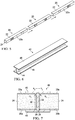
- a lightweight, flexible mandrel 20 broadly comprises an outer metal sleeve 22 and a lightweight, flexible inner core 24.
- the outer sleeve 22 may comprise a channel member 22a that is generally U-shaped in cross section defining an interior cavity 23, however other cross sectional shapes are possible, including for example and without limitation, a truncated U-shape with up-standing legs (not shown).
- the channel member 22a may be a closed tubular channel.
- the outer sleeve 22 has an outer tool surface 25 formed by top, side and bottom walls 32, 34, 36 of the channel member 22a.
- Top and bottom walls 32, 34 respectively, are each connected to the side wall 34 by a radiused edge 28 having a radius R 1 .
- the sleeve 22 may be formed of any of a variety of suitable, relatively thin-walled metals commonly used for durable tooling, such as Invar® metal.
- the inner core 24 substantially fills the inner cavity 23 of the channel member 22a and may comprise any suitable, lightweight material that is relatively flexible and yet possesses the stiffness needed to maintain the dimensions of the outer sleeve 22 and react forces applied to the mandrel 20 during vacuum bag compaction and/or autoclave processing.
- the material from which the core 24 or formed may comprise a suitable polymer such as, without limitation, an elastomeric rubber such as RTV silicone, a carbon foam or a closed cell foam, a flexible ceramic or a composite such as CFRP (carbon fiber reinforced plastic), capable of retaining its desired properties when subjected to the temperatures and pressures of the application, such as the temperatures and pressures experienced during curing within an autoclave (not shown).
- the mandrel 20 may include one or more portions 26 along its length that are flexible, allowing the tool surface 25 on sidewall 34 to flex to one or more desired contours related to surface features (not shown) of a part (not shown).
- the terms "contour” and “contours” as used herein is defined as including localized curves, contours, joggles, complex contours, ply pad-ups and ply drop-offs, steps and other ply variations and surface features to which the mandrel 20 may conform.
- the flexible portions 26 of the mandrel 20 are formed by a plurality of spaced apart, generally parallel slots 30 in sidewall 34, that extend substantially orthogonal to the longitudinal axis 35 of the mandrel 20.
- the sidewall 34 may have a wall thickness T that is suitable for the application, and may or may not be same thickness as that of the top and bottom walls 32, 36 respectively.
- the slots 30 extend through the sidewall 34, into the mandrel 20 to a depth D ( FIG. 3 ) that is generally substantially equal to the radius R 1 of the edges 28.
- the slot depth D may vary, depending upon the application, and may or may not be substantially equal to the radius R 1 of the edge 28, in other applications, depending upon the configuration and geometry of the part being formed.
- the depth D of the slots 30 may be greater than the radius R 1 , such that the slots 30 extend into the top and bottom walls 32, 36, respectively.
- the outer sleeve 22 may include one or more integral contours, tapers or steps conforming to the geometry of a part, which may be formed by any suitable process, such as, without limitation, hydroforming.
- the slots 30 each have a preselected width W, and are spaced apart from each other a distance S such that the mandrel 20 has the desired amount of flexibility to conform to contours of a part.
- the mandrel 20 may twist to some degree along its longitudinal axis 35 ( FIG. 1 ) in response to applied torsional forces.
- the back 38 of the channel member 22a is generally open in order to reduce the weight of the mandrel 20 while facilitating assembly of the sleeve 22 and the core 24, however, in other embodiments the channel member 22a may have a cross sectional shape that is closed, rather than open along one side.
- the channel member 22a may be formed of Invar® steel with a cross sectional area of approximately 2.5 inches by 4.0 inches, and a wall thickness T of approximately 0.062 inches.
- the radii R 1 may each be approximately 0.250 inches.
- the slots 30 are approximately 0.005 inches wide, 0.250 inches deep and are spaced apart from each other approximately 2 inches.
- FIG. 5 illustrates an alternate embodiment in which multiple channel members 22a are connected together end-to-end and assembled with an inner core 24 to form a single, long flexible mandrel 20 that may be used, for example, to form long stringers (not shown in FIG. 5 ) used in the aircraft industry.
- the channel members 22a may be joined together using butt joints (not shown), for example, by welding the adjacent ends of the channel members 22a together, however other types of joints may be used.
- a single, long metal sleeve 22 Once a single, long metal sleeve 22 has been formed using multiple channel members 22a, it may be filled with a suitable filler material as described previously, to form a single, continuous inner core 24.
- the inner core 24 may be formed as by molding and/or machining a material such as carbon foam which is then assembled with the metal outer sleeve 22. It may also be possible to join the channel sections 22a together to form a single long sleeve 22, and then insert a single long core 24 into the sleeve 22.
- the lightweight, flexible mandrel shown in FIGS. 1-4 may be used to layup, compress and/or cure a wide variety of parts having varying configurations and geometries.
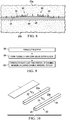
- a pair of the lightweight, flexible mandrels 20a, 20b may be form a tool assembly 40 used to fabricate a stringer 42 having a substantially I-shape cross section and including a web 44 and a pair of flanges 46, 48.
- the stringer 42 may be laid up using prepreg composite plies and conventional drape forming techniques.
- a pair of U-shaped members (not shown) can be laid up and joined together back-to-back, along with caps (not shown) and radius filler noodles (not shown) to form the I cross sectional shape shown in FIG. 7 .
- the tool assembly 40 along with the composite layup stringer 42 layup may be vacuum bagged, compacted and cured using a process and equipment similar to that disclosed in U.S. patent number 7,901,531 , the entire contents of which are incorporated by reference herein.
- the stringer 42 has a pair of Radii R 2 between the web 44 and the flanges 46. The Radii R 2 are formed and compacted by the radiused edges 28 on the flexible mandrels 20a, 20b.
- both of the mandrels 20a, 20b may have one or sets of slots 30 therein which render these portions inwardly flexible.
- the stringer 42 may include one or more contours along its length.
- the web 44 may comprise a plurality of ply laminations 45 that include a contour 52 to which the mandrel 20a must conform.
- the contour 52 is formed by ply pad-ups 50.
- the lightweight, flexible mandrel 20 may be fabricated by forming an outer sleeve 22 at step 56, and forming a flexible inner core 24 inside the sleeve 22 at 58.
- slots 30 are formed in at least a portion 26 of the outer sleeve 22, allowing the mandrel 20 to flex and conform to contours of a part being processed.
- the slots 30 may be formed by any suitable process, such as, for example and with limitation, machining the slots 30 using a wire EDM (electro-discharge machining) machine (not shown).
- wire EDM electro-discharge machining
- other types of metal working processes may be used to form relatively narrow slots 30, including but not limited to other types of machining, cutting and milling.
- FIG. 10 shows one technique for forming the outer sleeve 22.
- the technique may begin by providing substantially flat sheet 54 of metal.
- the metal sheet 54 is formed by any suitable process into an elongate channel member 22a having a U-shaped cross section.
- the surface of the channel member 22a will be sufficiently smooth to impart a smooth finish to the surface of the part, and not need to be machined to improve the tool surface finish.
- the slots 30 may be formed in the channel member 22a either before or after the inner core has been placed or form within the channel member 22a.
- Step 58 of the method shown in FIG, 9 may be performed using any of several alternate techniques.
- the cavity 23 within channel member 22a may be filled with a suitable, lightweight polymer material, such as a structural foam that assumes the internal shape of the cavity 23 ( FIG. 3 ) and is subsequently cured.
- a block (not shown) of high temperature structural foam, such as a carbon foam may be molded or cut to size and then inserted within and bonded to the channel member 22a.
- the inner core 24 need not be machined, but rather need only be cut to an approximately size that fits within and substantially fills the inner cavity 23 of the channel member 22a.
- Embodiments of the disclosure may be employed, without limitation, in the context of aircraft manufacturing and service method 62 as shown in Figure 11 and an aircraft 64 as shown in Figure 12 .
- aircraft manufacturing and service method 62 may include specification and design 66 of aircraft 64 in Figure 12 and material procurement 68.
- aircraft 64 in Figure 12 During production, component and subassembly manufacturing 70 and system integration 72 of aircraft 64 in Figure 12 takes place. Thereafter, aircraft 64 in Figure 12 may go through certification and delivery 74 in order to be placed in service 76. While in service 76 by a customer, aircraft 64 in Figure 12 is scheduled for routine maintenance and service 78, which may include modification, reconfiguration, refurbishment, and other maintenance or service.
- Each of the processes of aircraft manufacturing and service method 62 may be performed or carried out by a system integrator, a third party, and/or an operator.
- the operator may be a customer.
- a system integrator may include, without limitation, any number of aircraft manufacturers and major-system subcontractors
- a third party may include, without limitation, any number of vendors, subcontractors, and suppliers
- an operator may be an airline, a leasing company, a military entity, a service organization, and so on.
- aircraft 64 is produced by aircraft manufacturing and service method 62 in FIG. 1 and may include airframe 79 with plurality of systems 80 and interior 82.
- the disclosed mandrel may be used to fabricate various structural components of the airframe 79, such as stringers
- systems 80 include one or more of propulsion system 84, electrical system 86, hydraulic system 88, and environmental system 90. Any number of other systems may be included.
- Apparatuses and methods embodied herein may be employed during at least one of the stages of aircraft manufacturing and service method 62 in FIG. 11 .
- the phrase "at least one of”, when used with a list of items, means that different combinations of one or more of the listed items may be used and only one of each item in the list may be needed.
- "at least one of item A, item B, and item C" may include, for example, without limitation, item A or item A and item B. This example also may include item A, item B, and item C or item B and item C.
- components or subassemblies produced in component and subassembly manufacturing 70 in FIG. 11 may be fabricated or manufactured in a manner similar to components or subassemblies produced while aircraft 64 is in service 76 in FIG. 11 .
- a number of apparatus embodiments, method embodiments, or a combination thereof may be utilized during production stages, such as component and subassembly manufacturing 70 and system integration 72 in FIG. 11 .
- a number, when referring to items, means one or more items.
- a number of apparatus embodiments is one or more apparatus embodiments.
- a number of apparatus embodiments, method embodiments, or a combination thereof may be utilized while aircraft 64 is in service 76 and/or during maintenance and service 78 in FIG. 12 .
- the use of a number of the different advantageous embodiments may substantially expedite the assembly of and/or reduce the cost of aircraft 64.
Landscapes
- Engineering & Computer Science (AREA)
- Mechanical Engineering (AREA)
- Chemical & Material Sciences (AREA)
- Composite Materials (AREA)
- Moulding By Coating Moulds (AREA)
- Moulds For Moulding Plastics Or The Like (AREA)
Applications Claiming Priority (2)
| Application Number | Priority Date | Filing Date | Title |
|---|---|---|---|
| US13/271,489 US8534339B2 (en) | 2011-10-12 | 2011-10-12 | Lightweight flexible mandrel and method for making the same |
| PCT/US2012/054577 WO2013055477A2 (en) | 2011-10-12 | 2012-09-11 | Lightweight flexible mandrel and method for making the same |
Publications (2)
| Publication Number | Publication Date |
|---|---|
| EP2747972A2 EP2747972A2 (en) | 2014-07-02 |
| EP2747972B1 true EP2747972B1 (en) | 2018-03-07 |
Family
ID=46968366
Family Applications (1)
| Application Number | Title | Priority Date | Filing Date |
|---|---|---|---|
| EP12767154.3A Active EP2747972B1 (en) | 2011-10-12 | 2012-09-11 | Lightweight flexible mandrel and method for making the same |
Country Status (7)
| Country | Link |
|---|---|
| US (1) | US8534339B2 (ko) |
| EP (1) | EP2747972B1 (ko) |
| JP (1) | JP6031111B2 (ko) |
| KR (1) | KR102022130B1 (ko) |
| CN (1) | CN103857508B (ko) |
| CA (1) | CA2848202C (ko) |
| WO (1) | WO2013055477A2 (ko) |
Families Citing this family (20)
| Publication number | Priority date | Publication date | Assignee | Title |
|---|---|---|---|---|
| EP2411195A4 (en) * | 2009-03-27 | 2013-07-03 | Cutting Dynamics Inc | SYSTEM AND METHOD FOR FORMING TUBES FROM A THERMOPLASTIC COMPOSITE |
| US8534339B2 (en) | 2011-10-12 | 2013-09-17 | The Boeing Company | Lightweight flexible mandrel and method for making the same |
| US9248587B2 (en) * | 2012-07-05 | 2016-02-02 | General Electric Company | Apparatus for manufacturing a flanged composite component and methods of manufacturing the same |
| US9517606B2 (en) * | 2014-08-06 | 2016-12-13 | The Boeing Company | Composite structure and method of forming thereof |
| US10807280B2 (en) | 2015-06-22 | 2020-10-20 | The Boeing Company | Method of extracting a tooling mandrel from a composite laminate cavity |
| US11072157B2 (en) | 2015-06-23 | 2021-07-27 | The Boeing Company | Method and apparatus for forming contoured stiffeners |
| US11311969B2 (en) | 2015-11-06 | 2022-04-26 | The Boeing Company | Edge preparation for laser welding |
| CN107300160A (zh) * | 2017-07-12 | 2017-10-27 | 湖南粤港模科实业有限公司 | 一种分离式可弯曲定型的模条及由其构成的模条组 |
| JP6971690B2 (ja) * | 2017-08-03 | 2021-11-24 | 三菱重工業株式会社 | 可撓性マンドレル、複合材部品の製造方法 |
| JP6836474B2 (ja) * | 2017-08-03 | 2021-03-03 | 三菱重工業株式会社 | 可撓性マンドレル、複合材部品の製造方法 |
| US10882262B2 (en) | 2018-08-22 | 2021-01-05 | The Boeing Company | Flexible mandrel for forming composite structures |
| US11478958B2 (en) | 2018-10-18 | 2022-10-25 | The Boeing Company | Multi-component mandrel for processing a composite part and method for fabricating a composite part |
| US11220027B2 (en) | 2018-10-18 | 2022-01-11 | The Boeing Company | Mandrel for processing a composite part and method for fabricating a composite part |
| US11273582B2 (en) | 2018-10-18 | 2022-03-15 | The Boeing Company | Multi-segment mandrel for processing a composite part and method for fabricating a composite part |
| US11198267B2 (en) | 2018-10-29 | 2021-12-14 | The Boeing Company | Bulk factor compensated tool for fabrication of a composite part |
| CN114193688A (zh) * | 2020-09-17 | 2022-03-18 | 波音公司 | 包含平面外特征的复合桁条的净形状形成 |
| EP3970939A1 (en) | 2020-09-17 | 2022-03-23 | The Boeing Company | Constrained forming of contoured composite hat stringers |
| JP7533082B2 (ja) * | 2020-09-29 | 2024-08-14 | 住友ゴム工業株式会社 | 加圧治具、それを用いた繊維強化樹脂製パイプの製造方法及び製造装置 |
| US20230226724A1 (en) * | 2022-01-19 | 2023-07-20 | The Boeing Company | Reformable mandrel and method of making a composite part using a reformable mandrel |
| EP4353454A1 (en) * | 2022-10-11 | 2024-04-17 | Airbus Operations, S.L.U. | Method for manufacting stringers for aircrafts and stringer obtained by said method |
Family Cites Families (23)
| Publication number | Priority date | Publication date | Assignee | Title |
|---|---|---|---|---|
| US3795559A (en) * | 1971-10-01 | 1974-03-05 | Boeing Co | Aircraft fluted core radome and method for making the same |
| DE2457423C2 (de) * | 1974-12-05 | 1983-04-21 | Metall-Invent S.A., Zug | Verfahren und Vorrichtung zum Herstellen eines Stranges aus einer metallischen Schmelze |
| DE2557991C3 (de) | 1975-12-22 | 1978-11-16 | Reiner 1000 Berlin Larws | Formkern zum Erzeugen von Hohlräumen in Gießteilen |
| US4649012A (en) * | 1980-06-03 | 1987-03-10 | Maschinen Witte Kg | Method of shaping an elongated product |
| JPS5876217A (ja) * | 1981-10-31 | 1983-05-09 | Sekisui Chem Co Ltd | 強化プラスチツク曲管の成形用型及びその成形方法 |
| US4475976A (en) | 1983-12-23 | 1984-10-09 | The Boeing Company | Method and apparatus for forming composite material articles |
| DE3428282C1 (de) | 1984-08-01 | 1986-01-16 | Deutsche Forschungs- und Versuchsanstalt für Luft- und Raumfahrt e.V., 5300 Bonn | Entfernbarer Kern zur Herstellung rohrfoermiger Strukturen aus Faserverbundwerkstoffen |
| JPS62135347A (ja) * | 1985-12-09 | 1987-06-18 | Mitsubishi Electric Corp | 繊維強化プラスチツクの製造方法 |
| US4681724A (en) | 1986-04-28 | 1987-07-21 | United Technologies Corporation | Removable irreversibly shrinking male mandrel |
| DE3707634C1 (en) | 1987-03-10 | 1988-07-07 | Messerschmitt Boelkow Blohm | Device for producing a plastic body |
| US4976490A (en) * | 1988-10-05 | 1990-12-11 | Ford Motor Company | Reinforced composite structure |
| CA2069125A1 (en) * | 1991-07-01 | 1993-01-02 | Gary J. Jacaruso | Composite forming tool |
| US5387098A (en) * | 1992-04-23 | 1995-02-07 | The Boeing Company | Flexible reusable mandrels |
| FI98284C (fi) * | 1995-09-12 | 1997-05-26 | Uponor Bv | Laite ja menetelmä muoviputken valmistamiseksi |
| US5924193A (en) | 1997-02-10 | 1999-07-20 | Packard Hughes Interconnect Company | Method of making mandrels and circuits therefrom |
| US6059369A (en) | 1997-05-01 | 2000-05-09 | Lear Corporation | Composite vehicle seat back frame and method of manufacturing thereof |
| GB0213161D0 (en) * | 2002-06-07 | 2002-07-17 | Short Brothers Plc | A fibre reinforced composite component |
| US7357166B2 (en) * | 2004-11-24 | 2008-04-15 | The Boeing Company | Flexible mandrel for highly contoured composite stringer |
| US7497921B2 (en) | 2005-09-02 | 2009-03-03 | The Boeing Company | Stringer holding device |
| US7815160B2 (en) * | 2006-04-04 | 2010-10-19 | A & P Technology | Composite mandrel |
| GB0616121D0 (en) * | 2006-08-14 | 2006-09-20 | Airbus Uk Ltd | Moulding tool and method of manufacturing a part |
| US9327467B2 (en) * | 2008-07-10 | 2016-05-03 | The Boeing Company | Composite mandrel for autoclave curing applications |
| US8534339B2 (en) | 2011-10-12 | 2013-09-17 | The Boeing Company | Lightweight flexible mandrel and method for making the same |
-
2011
- 2011-10-12 US US13/271,489 patent/US8534339B2/en active Active
-
2012
- 2012-09-11 KR KR1020147006058A patent/KR102022130B1/ko active IP Right Grant
- 2012-09-11 CA CA2848202A patent/CA2848202C/en active Active
- 2012-09-11 WO PCT/US2012/054577 patent/WO2013055477A2/en active Application Filing
- 2012-09-11 CN CN201280049399.1A patent/CN103857508B/zh active Active
- 2012-09-11 EP EP12767154.3A patent/EP2747972B1/en active Active
- 2012-09-11 JP JP2014535721A patent/JP6031111B2/ja active Active
Also Published As
| Publication number | Publication date |
|---|---|
| KR20140075675A (ko) | 2014-06-19 |
| EP2747972A2 (en) | 2014-07-02 |
| US20130092323A1 (en) | 2013-04-18 |
| CN103857508A (zh) | 2014-06-11 |
| CN103857508B (zh) | 2017-02-15 |
| US8534339B2 (en) | 2013-09-17 |
| WO2013055477A3 (en) | 2013-08-01 |
| CA2848202A1 (en) | 2013-04-18 |
| KR102022130B1 (ko) | 2019-09-17 |
| JP2014532000A (ja) | 2014-12-04 |
| JP6031111B2 (ja) | 2016-11-24 |
| CA2848202C (en) | 2016-06-14 |
| WO2013055477A2 (en) | 2013-04-18 |
Similar Documents
| Publication | Publication Date | Title |
|---|---|---|
| EP2747972B1 (en) | Lightweight flexible mandrel and method for making the same | |
| CA2753251C (en) | Method and apparatus for fabricating highly contoured composite stiffeners with reduced wrinkling | |
| EP3015258B1 (en) | Method and apparatus for vacuum forming composite laminates | |
| US8691137B2 (en) | Method of molding partus using a tool sleeve for mold die | |
| CA2835892C (en) | Method and device for transporting, placing and compacting composite stiffeners | |
| US8465613B2 (en) | Method and apparatus for fabricating variable gauge, contoured composite stiffeners | |
| US6217000B1 (en) | Composite fabrication method and tooling to improve part consolidation | |
| US20180169991A1 (en) | Flexible Compactor with Reinforcing Spine | |
| EP2881238A1 (en) | Hybrid laminate and molded composite structures | |
| EP3970938B1 (en) | Tool and method for forming contoured composite stringers having reduced wrinkling | |
| US11426957B2 (en) | Flexible caul and method of making the same | |
| US20170182738A1 (en) | Composite Filler | |
| US10279572B2 (en) | Softening strip for controlling stress in joints at very low temperatures | |
| WO2007149547A2 (en) | Integrated composite structure |
Legal Events
| Date | Code | Title | Description |
|---|---|---|---|
| PUAI | Public reference made under article 153(3) epc to a published international application that has entered the european phase |
Free format text: ORIGINAL CODE: 0009012 |
|
| 17P | Request for examination filed |
Effective date: 20140325 |
|
| AK | Designated contracting states |
Kind code of ref document: A2 Designated state(s): AL AT BE BG CH CY CZ DE DK EE ES FI FR GB GR HR HU IE IS IT LI LT LU LV MC MK MT NL NO PL PT RO RS SE SI SK SM TR |
|
| RIN1 | Information on inventor provided before grant (corrected) |
Inventor name: PHAM, DOAN D. Inventor name: TOLLAN, MARK W. |
|
| DAX | Request for extension of the european patent (deleted) | ||
| 17Q | First examination report despatched |
Effective date: 20160810 |
|
| GRAP | Despatch of communication of intention to grant a patent |
Free format text: ORIGINAL CODE: EPIDOSNIGR1 |
|
| INTG | Intention to grant announced |
Effective date: 20170922 |
|
| RIC1 | Information provided on ipc code assigned before grant |
Ipc: B29C 33/40 20060101ALN20170912BHEP Ipc: B29C 33/48 20060101AFI20170912BHEP Ipc: B29C 33/38 20060101ALN20170912BHEP Ipc: B29C 33/76 20060101ALI20170912BHEP Ipc: B29L 31/30 20060101ALN20170912BHEP Ipc: B29D 99/00 20100101ALN20170912BHEP Ipc: B29C 70/44 20060101ALI20170912BHEP |
|
| GRAS | Grant fee paid |
Free format text: ORIGINAL CODE: EPIDOSNIGR3 |
|
| GRAA | (expected) grant |
Free format text: ORIGINAL CODE: 0009210 |
|
| AK | Designated contracting states |
Kind code of ref document: B1 Designated state(s): AL AT BE BG CH CY CZ DE DK EE ES FI FR GB GR HR HU IE IS IT LI LT LU LV MC MK MT NL NO PL PT RO RS SE SI SK SM TR |
|
| REG | Reference to a national code |
Ref country code: GB Ref legal event code: FG4D |
|
| REG | Reference to a national code |
Ref country code: CH Ref legal event code: EP Ref country code: AT Ref legal event code: REF Ref document number: 976061 Country of ref document: AT Kind code of ref document: T Effective date: 20180315 |
|
| REG | Reference to a national code |
Ref country code: IE Ref legal event code: FG4D |
|
| REG | Reference to a national code |
Ref country code: DE Ref legal event code: R096 Ref document number: 602012043740 Country of ref document: DE |
|
| REG | Reference to a national code |
Ref country code: NL Ref legal event code: MP Effective date: 20180307 |
|
| REG | Reference to a national code |
Ref country code: LT Ref legal event code: MG4D |
|
| PG25 | Lapsed in a contracting state [announced via postgrant information from national office to epo] |
Ref country code: ES Free format text: LAPSE BECAUSE OF FAILURE TO SUBMIT A TRANSLATION OF THE DESCRIPTION OR TO PAY THE FEE WITHIN THE PRESCRIBED TIME-LIMIT Effective date: 20180307 Ref country code: CY Free format text: LAPSE BECAUSE OF FAILURE TO SUBMIT A TRANSLATION OF THE DESCRIPTION OR TO PAY THE FEE WITHIN THE PRESCRIBED TIME-LIMIT Effective date: 20180307 Ref country code: HR Free format text: LAPSE BECAUSE OF FAILURE TO SUBMIT A TRANSLATION OF THE DESCRIPTION OR TO PAY THE FEE WITHIN THE PRESCRIBED TIME-LIMIT Effective date: 20180307 Ref country code: LT Free format text: LAPSE BECAUSE OF FAILURE TO SUBMIT A TRANSLATION OF THE DESCRIPTION OR TO PAY THE FEE WITHIN THE PRESCRIBED TIME-LIMIT Effective date: 20180307 Ref country code: FI Free format text: LAPSE BECAUSE OF FAILURE TO SUBMIT A TRANSLATION OF THE DESCRIPTION OR TO PAY THE FEE WITHIN THE PRESCRIBED TIME-LIMIT Effective date: 20180307 Ref country code: NO Free format text: LAPSE BECAUSE OF FAILURE TO SUBMIT A TRANSLATION OF THE DESCRIPTION OR TO PAY THE FEE WITHIN THE PRESCRIBED TIME-LIMIT Effective date: 20180607 |
|
| REG | Reference to a national code |
Ref country code: AT Ref legal event code: MK05 Ref document number: 976061 Country of ref document: AT Kind code of ref document: T Effective date: 20180307 |
|
| PG25 | Lapsed in a contracting state [announced via postgrant information from national office to epo] |
Ref country code: BG Free format text: LAPSE BECAUSE OF FAILURE TO SUBMIT A TRANSLATION OF THE DESCRIPTION OR TO PAY THE FEE WITHIN THE PRESCRIBED TIME-LIMIT Effective date: 20180607 Ref country code: SE Free format text: LAPSE BECAUSE OF FAILURE TO SUBMIT A TRANSLATION OF THE DESCRIPTION OR TO PAY THE FEE WITHIN THE PRESCRIBED TIME-LIMIT Effective date: 20180307 Ref country code: RS Free format text: LAPSE BECAUSE OF FAILURE TO SUBMIT A TRANSLATION OF THE DESCRIPTION OR TO PAY THE FEE WITHIN THE PRESCRIBED TIME-LIMIT Effective date: 20180307 Ref country code: GR Free format text: LAPSE BECAUSE OF FAILURE TO SUBMIT A TRANSLATION OF THE DESCRIPTION OR TO PAY THE FEE WITHIN THE PRESCRIBED TIME-LIMIT Effective date: 20180608 Ref country code: LV Free format text: LAPSE BECAUSE OF FAILURE TO SUBMIT A TRANSLATION OF THE DESCRIPTION OR TO PAY THE FEE WITHIN THE PRESCRIBED TIME-LIMIT Effective date: 20180307 |
|
| REG | Reference to a national code |
Ref country code: FR Ref legal event code: PLFP Year of fee payment: 7 |
|
| PG25 | Lapsed in a contracting state [announced via postgrant information from national office to epo] |
Ref country code: EE Free format text: LAPSE BECAUSE OF FAILURE TO SUBMIT A TRANSLATION OF THE DESCRIPTION OR TO PAY THE FEE WITHIN THE PRESCRIBED TIME-LIMIT Effective date: 20180307 Ref country code: RO Free format text: LAPSE BECAUSE OF FAILURE TO SUBMIT A TRANSLATION OF THE DESCRIPTION OR TO PAY THE FEE WITHIN THE PRESCRIBED TIME-LIMIT Effective date: 20180307 Ref country code: NL Free format text: LAPSE BECAUSE OF FAILURE TO SUBMIT A TRANSLATION OF THE DESCRIPTION OR TO PAY THE FEE WITHIN THE PRESCRIBED TIME-LIMIT Effective date: 20180307 Ref country code: PL Free format text: LAPSE BECAUSE OF FAILURE TO SUBMIT A TRANSLATION OF THE DESCRIPTION OR TO PAY THE FEE WITHIN THE PRESCRIBED TIME-LIMIT Effective date: 20180307 Ref country code: AL Free format text: LAPSE BECAUSE OF FAILURE TO SUBMIT A TRANSLATION OF THE DESCRIPTION OR TO PAY THE FEE WITHIN THE PRESCRIBED TIME-LIMIT Effective date: 20180307 |
|
| PG25 | Lapsed in a contracting state [announced via postgrant information from national office to epo] |
Ref country code: AT Free format text: LAPSE BECAUSE OF FAILURE TO SUBMIT A TRANSLATION OF THE DESCRIPTION OR TO PAY THE FEE WITHIN THE PRESCRIBED TIME-LIMIT Effective date: 20180307 Ref country code: SM Free format text: LAPSE BECAUSE OF FAILURE TO SUBMIT A TRANSLATION OF THE DESCRIPTION OR TO PAY THE FEE WITHIN THE PRESCRIBED TIME-LIMIT Effective date: 20180307 Ref country code: SK Free format text: LAPSE BECAUSE OF FAILURE TO SUBMIT A TRANSLATION OF THE DESCRIPTION OR TO PAY THE FEE WITHIN THE PRESCRIBED TIME-LIMIT Effective date: 20180307 Ref country code: CZ Free format text: LAPSE BECAUSE OF FAILURE TO SUBMIT A TRANSLATION OF THE DESCRIPTION OR TO PAY THE FEE WITHIN THE PRESCRIBED TIME-LIMIT Effective date: 20180307 |
|
| REG | Reference to a national code |
Ref country code: DE Ref legal event code: R097 Ref document number: 602012043740 Country of ref document: DE |
|
| PG25 | Lapsed in a contracting state [announced via postgrant information from national office to epo] |
Ref country code: PT Free format text: LAPSE BECAUSE OF FAILURE TO SUBMIT A TRANSLATION OF THE DESCRIPTION OR TO PAY THE FEE WITHIN THE PRESCRIBED TIME-LIMIT Effective date: 20180709 |
|
| PLBE | No opposition filed within time limit |
Free format text: ORIGINAL CODE: 0009261 |
|
| STAA | Information on the status of an ep patent application or granted ep patent |
Free format text: STATUS: NO OPPOSITION FILED WITHIN TIME LIMIT |
|
| PG25 | Lapsed in a contracting state [announced via postgrant information from national office to epo] |
Ref country code: DK Free format text: LAPSE BECAUSE OF FAILURE TO SUBMIT A TRANSLATION OF THE DESCRIPTION OR TO PAY THE FEE WITHIN THE PRESCRIBED TIME-LIMIT Effective date: 20180307 |
|
| 26N | No opposition filed |
Effective date: 20181210 |
|
| PG25 | Lapsed in a contracting state [announced via postgrant information from national office to epo] |
Ref country code: SI Free format text: LAPSE BECAUSE OF FAILURE TO SUBMIT A TRANSLATION OF THE DESCRIPTION OR TO PAY THE FEE WITHIN THE PRESCRIBED TIME-LIMIT Effective date: 20180307 |
|
| PG25 | Lapsed in a contracting state [announced via postgrant information from national office to epo] |
Ref country code: MC Free format text: LAPSE BECAUSE OF FAILURE TO SUBMIT A TRANSLATION OF THE DESCRIPTION OR TO PAY THE FEE WITHIN THE PRESCRIBED TIME-LIMIT Effective date: 20180307 |
|
| REG | Reference to a national code |
Ref country code: CH Ref legal event code: PL |
|
| REG | Reference to a national code |
Ref country code: BE Ref legal event code: MM Effective date: 20180930 |
|
| REG | Reference to a national code |
Ref country code: IE Ref legal event code: MM4A |
|
| PG25 | Lapsed in a contracting state [announced via postgrant information from national office to epo] |
Ref country code: LU Free format text: LAPSE BECAUSE OF NON-PAYMENT OF DUE FEES Effective date: 20180911 |
|
| PG25 | Lapsed in a contracting state [announced via postgrant information from national office to epo] |
Ref country code: IE Free format text: LAPSE BECAUSE OF NON-PAYMENT OF DUE FEES Effective date: 20180911 |
|
| PG25 | Lapsed in a contracting state [announced via postgrant information from national office to epo] |
Ref country code: BE Free format text: LAPSE BECAUSE OF NON-PAYMENT OF DUE FEES Effective date: 20180930 Ref country code: LI Free format text: LAPSE BECAUSE OF NON-PAYMENT OF DUE FEES Effective date: 20180930 Ref country code: CH Free format text: LAPSE BECAUSE OF NON-PAYMENT OF DUE FEES Effective date: 20180930 |
|
| REG | Reference to a national code |
Ref country code: DE Ref legal event code: R082 Ref document number: 602012043740 Country of ref document: DE Representative=s name: MAIER, LL.M., MICHAEL C., DE Ref country code: DE Ref legal event code: R082 Ref document number: 602012043740 Country of ref document: DE Representative=s name: BOULT WADE TENNANT LLP, DE |
|
| PG25 | Lapsed in a contracting state [announced via postgrant information from national office to epo] |
Ref country code: MT Free format text: LAPSE BECAUSE OF NON-PAYMENT OF DUE FEES Effective date: 20180911 |
|
| REG | Reference to a national code |
Ref country code: DE Ref legal event code: R082 Ref document number: 602012043740 Country of ref document: DE Representative=s name: BOULT WADE TENNANT LLP, DE |
|
| PG25 | Lapsed in a contracting state [announced via postgrant information from national office to epo] |
Ref country code: TR Free format text: LAPSE BECAUSE OF FAILURE TO SUBMIT A TRANSLATION OF THE DESCRIPTION OR TO PAY THE FEE WITHIN THE PRESCRIBED TIME-LIMIT Effective date: 20180307 |
|
| PG25 | Lapsed in a contracting state [announced via postgrant information from national office to epo] |
Ref country code: HU Free format text: LAPSE BECAUSE OF FAILURE TO SUBMIT A TRANSLATION OF THE DESCRIPTION OR TO PAY THE FEE WITHIN THE PRESCRIBED TIME-LIMIT; INVALID AB INITIO Effective date: 20120911 |
|
| PG25 | Lapsed in a contracting state [announced via postgrant information from national office to epo] |
Ref country code: MK Free format text: LAPSE BECAUSE OF NON-PAYMENT OF DUE FEES Effective date: 20180307 |
|
| PG25 | Lapsed in a contracting state [announced via postgrant information from national office to epo] |
Ref country code: IS Free format text: LAPSE BECAUSE OF FAILURE TO SUBMIT A TRANSLATION OF THE DESCRIPTION OR TO PAY THE FEE WITHIN THE PRESCRIBED TIME-LIMIT Effective date: 20180707 |
|
| P01 | Opt-out of the competence of the unified patent court (upc) registered |
Effective date: 20230516 |
|
| PGFP | Annual fee paid to national office [announced via postgrant information from national office to epo] |
Ref country code: IT Payment date: 20230921 Year of fee payment: 12 Ref country code: GB Payment date: 20230927 Year of fee payment: 12 |
|
| PGFP | Annual fee paid to national office [announced via postgrant information from national office to epo] |
Ref country code: FR Payment date: 20230925 Year of fee payment: 12 Ref country code: DE Payment date: 20230927 Year of fee payment: 12 |