EP2747320A2 - Verfahren und vorrichtung zur übertragung von uplink-referenzsignalen in einem drahtlosen kommunikationssystem - Google Patents
Verfahren und vorrichtung zur übertragung von uplink-referenzsignalen in einem drahtlosen kommunikationssystem Download PDFInfo
- Publication number
- EP2747320A2 EP2747320A2 EP12824600.6A EP12824600A EP2747320A2 EP 2747320 A2 EP2747320 A2 EP 2747320A2 EP 12824600 A EP12824600 A EP 12824600A EP 2747320 A2 EP2747320 A2 EP 2747320A2
- Authority
- EP
- European Patent Office
- Prior art keywords
- identifier
- different
- sequence
- cell
- dmrs
- Prior art date
- Legal status (The legal status is an assumption and is not a legal conclusion. Google has not performed a legal analysis and makes no representation as to the accuracy of the status listed.)
- Granted
Links
- 238000000034 method Methods 0.000 title claims abstract description 77
- 238000004891 communication Methods 0.000 title claims abstract description 32
- 230000005540 biological transmission Effects 0.000 claims description 68
- 125000004122 cyclic group Chemical group 0.000 claims description 50
- 230000011664 signaling Effects 0.000 claims description 4
- 108010076504 Protein Sorting Signals Proteins 0.000 description 13
- 230000015654 memory Effects 0.000 description 9
- 230000004044 response Effects 0.000 description 8
- 238000010586 diagram Methods 0.000 description 5
- 230000006866 deterioration Effects 0.000 description 4
- 230000006870 function Effects 0.000 description 4
- 238000013468 resource allocation Methods 0.000 description 4
- 210000001520 comb Anatomy 0.000 description 3
- 238000005516 engineering process Methods 0.000 description 3
- 238000005562 fading Methods 0.000 description 3
- PCHJSUWPFVWCPO-UHFFFAOYSA-N gold Chemical group [Au] PCHJSUWPFVWCPO-UHFFFAOYSA-N 0.000 description 3
- 230000010363 phase shift Effects 0.000 description 3
- 230000008569 process Effects 0.000 description 3
- 230000002159 abnormal effect Effects 0.000 description 2
- 230000008859 change Effects 0.000 description 2
- 230000007774 longterm Effects 0.000 description 2
- 239000011159 matrix material Substances 0.000 description 2
- 230000007246 mechanism Effects 0.000 description 2
- 101000741965 Homo sapiens Inactive tyrosine-protein kinase PRAG1 Proteins 0.000 description 1
- 102100038659 Inactive tyrosine-protein kinase PRAG1 Human genes 0.000 description 1
- 230000004913 activation Effects 0.000 description 1
- 230000002776 aggregation Effects 0.000 description 1
- 238000004220 aggregation Methods 0.000 description 1
- 230000001413 cellular effect Effects 0.000 description 1
- 238000005352 clarification Methods 0.000 description 1
- 230000003247 decreasing effect Effects 0.000 description 1
- 230000001419 dependent effect Effects 0.000 description 1
- 230000000694 effects Effects 0.000 description 1
- 238000013507 mapping Methods 0.000 description 1
- 238000010295 mobile communication Methods 0.000 description 1
- 238000012986 modification Methods 0.000 description 1
- 230000004048 modification Effects 0.000 description 1
- 238000012545 processing Methods 0.000 description 1
- 238000000926 separation method Methods 0.000 description 1
Images


Classifications
-
- H—ELECTRICITY
- H04—ELECTRIC COMMUNICATION TECHNIQUE
- H04J—MULTIPLEX COMMUNICATION
- H04J11/00—Orthogonal multiplex systems, e.g. using WALSH codes
- H04J11/0069—Cell search, i.e. determining cell identity [cell-ID]
-
- H—ELECTRICITY
- H04—ELECTRIC COMMUNICATION TECHNIQUE
- H04W—WIRELESS COMMUNICATION NETWORKS
- H04W72/00—Local resource management
- H04W72/20—Control channels or signalling for resource management
- H04W72/21—Control channels or signalling for resource management in the uplink direction of a wireless link, i.e. towards the network
-
- H—ELECTRICITY
- H04—ELECTRIC COMMUNICATION TECHNIQUE
- H04B—TRANSMISSION
- H04B7/00—Radio transmission systems, i.e. using radiation field
- H04B7/02—Diversity systems; Multi-antenna system, i.e. transmission or reception using multiple antennas
- H04B7/022—Site diversity; Macro-diversity
- H04B7/024—Co-operative use of antennas of several sites, e.g. in co-ordinated multipoint or co-operative multiple-input multiple-output [MIMO] systems
-
- H—ELECTRICITY
- H04—ELECTRIC COMMUNICATION TECHNIQUE
- H04B—TRANSMISSION
- H04B7/00—Radio transmission systems, i.e. using radiation field
- H04B7/24—Radio transmission systems, i.e. using radiation field for communication between two or more posts
- H04B7/26—Radio transmission systems, i.e. using radiation field for communication between two or more posts at least one of which is mobile
- H04B7/2603—Arrangements for wireless physical layer control
- H04B7/2606—Arrangements for base station coverage control, e.g. by using relays in tunnels
-
- H—ELECTRICITY
- H04—ELECTRIC COMMUNICATION TECHNIQUE
- H04L—TRANSMISSION OF DIGITAL INFORMATION, e.g. TELEGRAPHIC COMMUNICATION
- H04L27/00—Modulated-carrier systems
- H04L27/26—Systems using multi-frequency codes
- H04L27/2601—Multicarrier modulation systems
- H04L27/2602—Signal structure
- H04L27/261—Details of reference signals
-
- H—ELECTRICITY
- H04—ELECTRIC COMMUNICATION TECHNIQUE
- H04L—TRANSMISSION OF DIGITAL INFORMATION, e.g. TELEGRAPHIC COMMUNICATION
- H04L5/00—Arrangements affording multiple use of the transmission path
- H04L5/003—Arrangements for allocating sub-channels of the transmission path
- H04L5/0032—Distributed allocation, i.e. involving a plurality of allocating devices, each making partial allocation
- H04L5/0035—Resource allocation in a cooperative multipoint environment
-
- H—ELECTRICITY
- H04—ELECTRIC COMMUNICATION TECHNIQUE
- H04L—TRANSMISSION OF DIGITAL INFORMATION, e.g. TELEGRAPHIC COMMUNICATION
- H04L5/00—Arrangements affording multiple use of the transmission path
- H04L5/003—Arrangements for allocating sub-channels of the transmission path
- H04L5/0048—Allocation of pilot signals, i.e. of signals known to the receiver
- H04L5/0051—Allocation of pilot signals, i.e. of signals known to the receiver of dedicated pilots, i.e. pilots destined for a single user or terminal
-
- H—ELECTRICITY
- H04—ELECTRIC COMMUNICATION TECHNIQUE
- H04L—TRANSMISSION OF DIGITAL INFORMATION, e.g. TELEGRAPHIC COMMUNICATION
- H04L5/00—Arrangements affording multiple use of the transmission path
- H04L5/003—Arrangements for allocating sub-channels of the transmission path
- H04L5/0058—Allocation criteria
- H04L5/0073—Allocation arrangements that take into account other cell interferences
-
- H—ELECTRICITY
- H04—ELECTRIC COMMUNICATION TECHNIQUE
- H04W—WIRELESS COMMUNICATION NETWORKS
- H04W56/00—Synchronisation arrangements
- H04W56/0005—Synchronisation arrangements synchronizing of arrival of multiple uplinks
-
- H—ELECTRICITY
- H04—ELECTRIC COMMUNICATION TECHNIQUE
- H04W—WIRELESS COMMUNICATION NETWORKS
- H04W72/00—Local resource management
- H04W72/02—Selection of wireless resources by user or terminal
-
- H—ELECTRICITY
- H04—ELECTRIC COMMUNICATION TECHNIQUE
- H04W—WIRELESS COMMUNICATION NETWORKS
- H04W72/00—Local resource management
- H04W72/04—Wireless resource allocation
- H04W72/044—Wireless resource allocation based on the type of the allocated resource
- H04W72/0446—Resources in time domain, e.g. slots or frames
-
- H—ELECTRICITY
- H04—ELECTRIC COMMUNICATION TECHNIQUE
- H04J—MULTIPLEX COMMUNICATION
- H04J2211/00—Orthogonal indexing scheme relating to orthogonal multiplex systems
- H04J2211/001—Orthogonal indexing scheme relating to orthogonal multiplex systems using small cells within macro cells, e.g. femto, pico or microcells
-
- H—ELECTRICITY
- H04—ELECTRIC COMMUNICATION TECHNIQUE
- H04J—MULTIPLEX COMMUNICATION
- H04J2211/00—Orthogonal indexing scheme relating to orthogonal multiplex systems
- H04J2211/003—Orthogonal indexing scheme relating to orthogonal multiplex systems within particular systems or standards
- H04J2211/005—Long term evolution [LTE]
-
- H—ELECTRICITY
- H04—ELECTRIC COMMUNICATION TECHNIQUE
- H04J—MULTIPLEX COMMUNICATION
- H04J2211/00—Orthogonal indexing scheme relating to orthogonal multiplex systems
- H04J2211/003—Orthogonal indexing scheme relating to orthogonal multiplex systems within particular systems or standards
- H04J2211/006—Single carrier frequency division multiple access [SC FDMA]
-
- H—ELECTRICITY
- H04—ELECTRIC COMMUNICATION TECHNIQUE
- H04L—TRANSMISSION OF DIGITAL INFORMATION, e.g. TELEGRAPHIC COMMUNICATION
- H04L5/00—Arrangements affording multiple use of the transmission path
- H04L5/0001—Arrangements for dividing the transmission path
- H04L5/0014—Three-dimensional division
- H04L5/0016—Time-frequency-code
-
- H—ELECTRICITY
- H04—ELECTRIC COMMUNICATION TECHNIQUE
- H04L—TRANSMISSION OF DIGITAL INFORMATION, e.g. TELEGRAPHIC COMMUNICATION
- H04L5/00—Arrangements affording multiple use of the transmission path
- H04L5/003—Arrangements for allocating sub-channels of the transmission path
- H04L5/0053—Allocation of signaling, i.e. of overhead other than pilot signals
- H04L5/0055—Physical resource allocation for ACK/NACK
-
- H—ELECTRICITY
- H04—ELECTRIC COMMUNICATION TECHNIQUE
- H04L—TRANSMISSION OF DIGITAL INFORMATION, e.g. TELEGRAPHIC COMMUNICATION
- H04L5/00—Arrangements affording multiple use of the transmission path
- H04L5/003—Arrangements for allocating sub-channels of the transmission path
- H04L5/0053—Allocation of signaling, i.e. of overhead other than pilot signals
- H04L5/0057—Physical resource allocation for CQI
-
- H—ELECTRICITY
- H04—ELECTRIC COMMUNICATION TECHNIQUE
- H04W—WIRELESS COMMUNICATION NETWORKS
- H04W88/00—Devices specially adapted for wireless communication networks, e.g. terminals, base stations or access point devices
- H04W88/02—Terminal devices
Definitions
- the present invention relates to wireless communications, and more particularly, to a method and apparatus for transmitting an uplink reference signal in a wireless communication system.
- the next-generation multimedia wireless communication systems which are recently being actively researched are required to process and transmit various pieces of information, such as video and wireless data as well as the initial voice-centered services.
- the 4th generation wireless communication systems which are now being developed subsequently to the 3rd generation wireless communication systems are aiming at supporting high-speed data service of downlink 1 Gbps (Gigabits per second) and uplink 500 Mbps (Megabits per second).
- the object of the wireless communication system is to establish reliable communications between a number of users irrespective of their positions and mobility.
- a wireless channel has abnormal characteristics, such as path loss, noise, a fading phenomenon due to multipath, inter-symbol interference (ISI), and the Doppler Effect resulting from the mobility of a user equipment.
- ISI inter-symbol interference
- a variety of techniques are being developed in order to overcome the abnormal characteristics of the wireless channel and to increase the reliability of wireless communication.
- RS reference signal
- a subcarrier used to transmit the reference signal is referred to as a reference signal subcarrier, and a subcarrier used to transmit data is referred to as a data subcarrier.
- a method of assigning the reference signal includes a method of assigning the reference signal to all the subcarriers and a method of assigning the reference signal between data subcarriers.
- the method of assigning the reference signal to all the subcarriers is performed using a signal including only the reference signal, such as a preamble signal, in order to obtain the throughput of channel estimation. If this method is used, the performance of channel estimation can be improved as compared with the method of assigning the reference signal between data subcarriers because the density of reference signals is in general high.
- the method of assigning the reference signal between data subcarriers is used in order to increase the amount of transmitted data. If the method of assigning the reference signal between data subcarriers is used, the performance of channel estimation can be deteriorated because the density of reference signals is low. Accordingly, the reference signals should be properly arranged in order to minimize such deterioration.
- a receiver can estimate a channel by separating information about a reference signal from a received signal because it knows the information about a reference signal and can accurately estimate data, transmitted by a transmit stage, by compensating for an estimated channel value.
- the reference signal transmitted by the transmitter is p
- channel information experienced by the reference signal during transmission is h
- thermal noise occurring in the receiver is n
- the signal received by the receiver is y
- it can result in y h ⁇ p+n.
- the receiver since the receiver already knows the reference signal p, it can estimate a channel information value ⁇ using Equation 1 in the case in which a Least Square (LS) method is used.
- the accuracy of the channel estimation value ⁇ estimated using the reference signal p is determined by the value n ⁇ .
- the value n ⁇ must converge on 0.
- the influence of the value n ⁇ has to be minimized by estimating a channel using a large number of reference signals.
- a variety of algorithms for a better channel estimation performance may exist.
- Deployment scenario A represents the network that is made up of the indoor and outdoor low power radio remote heads (RRHs) located within the coverage of the macro cell, and the transmission/reception point generated by the RRHs has the cell ID that is identical to that of the macro cell.
- Deployment scenario A may be called to coordinated multi-point (CoMP) scenario 4.
- Deployment scenario B represents the network that is made up of indoor and outdoor small cells only.
- Deployment scenario C represents the network that is made up of indoor and outdoor low power RRHs only, and all of the transmission/reception points generated by the RRHs have the same cell IDs.
- Deployment scenario D represents the network that is made up of the heterogeneous deployment of the small cell within the indoor and outdoor coverage, and the low power RRHs located in the coverage of the macro cell have a different cell ID with the macro cell. Deployment scenario D may be called to CoMP scenario 3.
- DMRS downlink demodulation reference signal
- the present invention provides a method and apparatus for transmitting an uplink reference signal in a wireless communication system.
- the present invention provides a method for applying a virtual cell identifier (ID), an orthogonal cover code (OCC), a cyclic shift, and the like, in order to guarantee orthogonality of uplink (UL) demodulation reference signals (DMRSs) of different user equipments, which belong to different cells with one another.
- ID virtual cell identifier
- OCC orthogonal cover code
- DMRSs demodulation reference signals
- a method for receiving, by a macro eNodeB (eNB), an uplink (UL) reference signal (RS) in a wireless communication system includes allocating a first identifier to a first user equipment (UE) which is served by the macro eNB, allocating a second identifier to a second UE which is served by a pico eNB, which has the same cell identifier (ID) as the macro eNB and exists within a coverage of the macro eNB, receiving a first UL RS which is generated based on the first identifier through a first bandwidth, from the first UE, and receiving a second UL RS which is generated based on the second identifier through a second bandwidth that overlaps with the first bandwidth, from the second UE.
- UE user equipment
- ID cell identifier
- the first identifier and the second identifier may be different virtual cell IDs each other.
- the first identifier and the second identifier may be different cyclic shifts each other.
- the first UL RS and the second UL RS may be the first UL demodulation reference signal (DMRS) and the second UL DMRS, respectively.
- DMRS first UL demodulation reference signal
- the first identifier and the second identifier may be different orthogonal cover code (OCC) indices each other.
- OCC orthogonal cover code
- the first UL RS and the second UL RS may be a first UL sounding reference signal (SRS) and a second UL SRS, respectively.
- SRS first UL sounding reference signal
- the first identifier and the second identifier may be different transmission comb indices each other.
- the first identifier and the second identifier may be allocated through a physical downlink control channel (PDCCH), or allocated through a radio resource control (RRC) signaling.
- PDCCH physical downlink control channel
- RRC radio resource control
- Cyclic shift hopping patterns of the first UL RS and the second UL RS may be identical.
- the cyclic shift hopping patterns of the first UL RS and the second UL RS may be configured based on the cell ID of the macro eNB and the cell ID of the pico eNB, which are identical.
- a sequence group hopping and a sequence hopping among slots may be not applied for the first UL RS and the second UL RS.
- a width of the first bandwidth and a width of the second bandwidth may be different each other.
- a macro eNodeB for receiving an uplink (UL) reference signal (RS) in a wireless communication system.
- the macro eNB includes a radio frequency (RF) unit for transmitting or receiving a radio signal, and a processor connected to the RF unit, and configured to allocate a first identifier to a first user equipment (UE) which is served by the macro eNB, allocate a second identifier to a second UE which is served by a pico eNB, which has the same cell identifier (ID) as the macro eNB and exists within a coverage of the macro eNB, receive a first UL RS which is generated based on the first identifier through a first bandwidth, from the first UE, and receive a second UL RS which is generated based on the second identifier through a second bandwidth that overlaps with the first bandwidth, from the second UE.
- RF radio frequency
- CoMP scenario 4 the orthogonality of the UL DMRSs of different user equipments, which belong to different cells with one another, may be guaranteed.
- the following technique may be used for various wireless communication systems such as code division multiple access (CDMA), a frequency division multiple access (FDMA), time division multiple access (TDMA), orthogonal frequency division multiple access (OFDMA), single carrier-frequency division multiple access (SC-FDMA), and the like.
- CDMA may be implemented as a radio technology such as universal terrestrial radio access (UTRA) or CDMA2000.
- TDMA may be implemented as a radio technology such as a global system for mobile communications (GSM)/general packet radio service (GPRS)/enhanced data rates for GSM evolution (EDGE).
- GSM global system for mobile communications
- GPRS general packet radio service
- EDGE enhanced data rates for GSM evolution
- the OFDMA may be implemented by a radio technology such as institute of electrical and electronics engineers (IEEE) 802.11 (Wi-Fi), IEEE 802.16 (WiMAX), IEEE 802.20, E-UTRA (Evolved UTRA), and the like.
- IEEE 802.16m an evolution of IEEE 802.16e, provides backward compatibility with a system based on IEEE 802.16e.
- the UTRA is part of a universal mobile telecommunications system (UMTS).
- 3 rd generation partnership project (3GPP) long term evolution (LTE) is part of an evolved UMTS (E-UMTS) using the E-UTRA, which employs the OFDMA in downlink and the SC-FDMA in uplink.
- LTE-advanced (LTE-A) is an evolution of 3GPP LTE.
- LTE-A Long Term Evolution-A
- the technical concept of the present invention is not meant to be limited thereto.
- FIG. 1 shows a wireless communication system
- the wireless communication system 10 includes at least one base station (BS) 11.
- BSs 11 provide a communication service to particular geographical areas 15a, 15b, and 15c (which are generally called cells). Each cell may be divided into a plurality of areas (which are called sectors).
- a user equipment (UE) 12 may be fixed or mobile and may be referred to by other names such as mobile station (MS), mobile user equipment (MT), user user equipment (UT), subscriber station (SS), wireless device, personal digital assistant (PDA), wireless modem, handheld device.
- the BS 11 generally refers to a fixed station that communicates with the UE 12 and may be called by other names such as evolved-NodeB (eNB), base transceiver system (BTS), access point (AP), etc.
- eNB evolved-NodeB
- BTS base transceiver system
- AP access point
- a UE belongs to one cell, and the cell to which a UE belongs is called a serving cell.
- a BS providing a communication service to the serving cell is called a serving BS.
- the wireless communication system is a cellular system, so a different cell adjacent to the serving cell exists.
- the different cell adjacent to the serving cell is called a neighbor cell.
- a BS providing a communication service to the neighbor cell is called a neighbor BS.
- the serving cell and the neighbor cell are relatively determined based on a UE.
- downlink refers to communication from the BS 11 to the UE 12
- uplink refers to communication from the UE 12 to the BS 11.
- a transmitter may be part of the BS 11 and a receiver may be part of the UE 12.
- a transmitter may be part of the UE 12 and a receiver may be part of the BS 11.
- the wireless communication system may be any one of a multiple-input multiple-output (MIMO) system, a multiple-input single-output (MISO) system, a single-input single-output (SISO) system, and a single-input multiple-output (SIMO) system.
- MIMO multiple-input multiple-output
- MISO multiple-input single-output
- SISO single-input single-output
- SIMO single-input multiple-output
- the MIMO system uses a plurality of transmission antennas and a plurality of reception antennas.
- the MISO system uses a plurality of transmission antennas and a single reception antenna.
- the SISO system uses a single transmission antenna and a single reception antenna.
- the SIMO system uses a single transmission antenna and a plurality of reception antennas.
- a transmission antenna refers to a physical or logical antenna used for transmitting a signal or a stream
- a reception antenna refers to a physical or logical antenna used
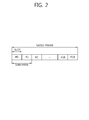
- FIG. 2 shows a structure of a radio frame in 3GPP LTE.
- the radio frame includes 10 subframes, and one subframe includes two slots.
- the slots in the radio frame are numbered by #0 to #19.
- a time taken for transmitting one subframe is called a transmission time interval (TTI).
- the TTI may be a scheduling unit for a data transmission.
- a radio frame may have a length of 10 ms, a subframe may have a length of 1 ms, and a slot may have a length of 0.5 ms.
- One slot includes a plurality of orthogonal frequency division multiplexing (OFDM) symbols in a time domain and a plurality of subcarriers in a frequency domain. Since 3GPP LTE uses OFDMA in downlink, the OFDM symbols are used to express a symbol period. The OFDM symbols may be called by other names depending on a multiple-access scheme. For example, when SC-FDMA is in use as an uplink multi-access scheme, the OFDM symbols may be called SC-FDMA symbols.
- a resource block (RB), a resource allocation unit includes a plurality of continuous subcarriers in a slot.
- the structure of the radio frame is merely an example. Namely, the number of subframes included in a radio frame, the number of slots included in a subframe, or the number of OFDM symbols included in a slot may vary.
- 3GPP LTE defines that one slot includes seven OFDM symbols in a normal cyclic prefix (CP) and one slot includes six OFDM symbols in an extended CP.
- CP normal cyclic prefix
- the wireless communication system may be divided into a frequency division duplex (FDD) scheme and a time division duplex (TDD) scheme.
- FDD frequency division duplex
- TDD time division duplex
- an uplink transmission and a downlink transmission are made at different frequency bands.
- an uplink transmission and a downlink transmission are made during different periods of time at the same frequency band.
- a channel response of the TDD scheme is substantially reciprocal. This means that a downlink channel response and an uplink channel response are almost the same in a given frequency band.
- the TDD-based wireless communication system is advantageous in that the downlink channel response can be obtained from the uplink channel response.
- the entire frequency band is time-divided for uplink and downlink transmissions, so a downlink transmission by the BS and an uplink transmission by the UE cannot be simultaneously performed.
- the uplink transmission and the downlink transmission are performed in different subframes.
- FIG. 3 shows an example of a resource grid of a single downlink slot.
- a downlink slot includes a plurality of OFDM symbols in the time domain and NRB number of resource blocks (RBs) in the frequency domain.
- the NRB number of resource blocks included in the downlink slot is dependent upon a downlink transmission bandwidth set in a cell.
- NRB may be any one of 6 to 110.
- One resource block includes a plurality of subcarriers in the frequency domain.
- An uplink slot may have the same structure as that of the downlink slot.
- Each element on the resource grid is called a resource element.
- the resource elements on the resource grid can be identified by a pair of indices (k,l) in the slot.
- 1 is an OFDM symbol index in the time domain.
- one resource block includes 7x12 resource elements made up of seven OFDM symbols in the time domain and twelve subcarriers in the frequency domain, but the number of OFDM symbols and the number of subcarriers in the resource block are not limited thereto.
- the number of OFDM symbols and the number of subcarriers may vary depending on the length of a CP, frequency spacing, and the like. For example, in case of a normal CP, the number of OFDM symbols is 7, and in case of an extended CP, the number of OFDM symbols is 6.
- One of 128, 256, 512, 1024, 1536, and 2048 may be selectively used as the number of subcarriers in one OFDM symbol.
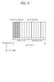
- FIG. 4 shows a structure of a downlink subframe.
- a downlink subframe includes two slots in the time domain, and each of the slots includes seven OFDM symbols in the normal CP.
- First three OFDM symbols (maximum four OFDM symbols for a 1.4 MHz bandwidth) of a first slot in the subframe corresponds to a control region to which control channels are allocated, and the other remaining OFDM symbols correspond to a data region to which a physical downlink shared channel (PDSCH) is allocated.
- PDSCH physical downlink shared channel
- the PDCCH may carry a transmission format and a resource allocation of a downlink shared channel (DL-SCH), resource allocation information of an uplink shared channel (UL-SCH), paging information on a PCH, system information on a DL-SCH, a resource allocation of an higher layer control message such as a random access response transmitted via a PDSCH, a set of transmission power control commands with respect to individual UEs in a certain UE group, an activation of a voice over internet protocol (VoIP), and the like.
- a plurality of PDCCHs may be transmitted in the control region, and a UE can monitor a plurality of PDCCHs.
- the PDCCHs are transmitted on one or an aggregation of a plurality of consecutive control channel elements (CCE).
- CCE control channel elements
- the CCE is a logical allocation unit used to provide a coding rate according to the state of a wireless channel.
- the CCE corresponds to a plurality of resource element groups.
- the format of the PDCCH and an available number of bits of the PDCCH are determined according to an associative relation between the number of the CCEs and a coding rate provided by the CCEs.
- the BS determines a PDCCH format according to a DCI to be transmitted to the UE, and attaches a cyclic redundancy check (CRC) to the DCI.
- CRC cyclic redundancy check
- a unique radio network temporary identifier (RNTI) is masked on the CRC according to the owner or the purpose of the PDCCH.
- RNTI radio network temporary identifier
- a unique identifier e.g., a cell-RNTI (C-RNTI), of the UE, may be masked on the CRC.
- a paging indication identifier e.g., a paging-RNTI (P-RNTI)
- P-RNTI paging-RNTI
- SIB system information block
- SI-RNTI system information-RNTI
- RA-RNTI random access-RNTI
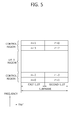
- FIG. 5 shows a structure of an uplink subframe.
- An uplink subframe may be divided into a control region and a data region in the frequency domain.
- a physical uplink control channel (PUCCH) for transmitting uplink control information is allocated to the control region.
- a physical uplink shared channel (PUCCH) for transmitting data is allocated to the data region.
- the UE may support a simultaneous transmission of the PUSCH and the PUCCH.
- the PUCCH for a UE is allocated by a pair of RBs in a subframe.
- the resource blocks belonging to the pair of RBs occupy different subcarriers in first and second slots, respectively.
- the frequency occupied by the RBs belonging to the pair of RBs is changed based on a slot boundary. This is said that the pair of RBs allocated to the PUCCH is frequency-hopped at the slot boundary.
- the UE can obtain a frequency diversity gain by transmitting uplink control information through different subcarriers according to time.
- m is a position index indicating the logical frequency domain positions of the pair of RBs allocated to the PUCCH in the subframe.
- Uplink control information transmitted on the PUCCH may include a hybrid automatic repeat request (HARQ) acknowledgement/non-acknowledgement (ACK/NACK), a channel quality indicator (CQI) indicating the state of a downlink channel, a scheduling request (SR), and the like.
- HARQ hybrid automatic repeat request
- ACK/NACK acknowledgement/non-acknowledgement
- CQI channel quality indicator
- SR scheduling request
- the PUSCH is mapped to an uplink shared channel (UL-SCH), a transport channel.
- Uplink data transmitted on the PUSCH may be a transport block, a data block for the UL-SCH transmitted during the TTI.
- the transport block may be user information.
- the uplink data may be multiplexed data.
- the multiplexed data may be data obtained by multiplexing the transport block for the UL-SCH and control information.
- control information multiplexed to data may include a CQI, a precoding matrix indicator (PMI), an HARQ, a rank indicator (RI), or the like.
- the uplink data may include only control information.
- a UL reference signal is described below.
- the reference signal is transmitted in the form of a sequence.
- a specific sequence may be used as the reference signal sequence without a special limit.
- a phase shift keying (PSK)-based computer generated sequence may be used as the reference signal sequence.
- PSK include binary phase shift keying (BPSK) and quadrature phase shift keying (QPSK).
- BPSK binary phase shift keying
- QPSK quadrature phase shift keying
- a constant amplitude zero auto-correlation (CAZAC) sequence may be used as the reference signal sequence.
- the CAZAC sequence include a Zadoff-Chu (ZC)-based sequence, a ZC sequence with cyclic extension, and a ZC sequence with truncation.
- PN pseudo-random
- Examples of the PN sequence include an m-sequence, a computer-generated sequence, a gold sequence, and a Kasami sequence.
- a cyclically shifted sequence may be used as the reference signal sequence.
- a UL reference signal may be divided into a demodulation reference signal (DMRS) and a sounding reference signal (SRS).
- the DMRS is a reference signal used in channel estimation for the demodulation of a received signal.
- the DMRS may be associated with the transmission of a PUSCH or PUCCH.
- the SRS is a reference signal transmitted from a UE to a BS for UL scheduling.
- the BS estimates an UL channel through the received SRS and uses the estimated UL channel in UL scheduling.
- the SRS is not associated with the transmission of a PUSCH or PUCCH.
- the same kind of a basic sequence may be used for the DMRS and the SRS.
- precoding applied to the DMRS may be the same as precoding applied to a PUSCH.
- Cyclic shift separation is a primary scheme for multiplexing the DMRS.
- the SRS may not be precoded and may be an antenna-specific reference signal.
- a reference signal sequence r u,v ( ⁇ )(n) may be defined based on a basic sequence b u,v (n) and a cyclic shift ⁇ according to Equation 2.
- r u , v ⁇ n e j ⁇ n ⁇ b u , v n , 0 ⁇ n ⁇ M sc RS
- r u ,v ⁇ n e j ⁇ n ⁇ b u , v n , 0 ⁇ n ⁇ M sc RS
- M sc RS (1 ⁇ m ⁇ N RB max,UL ) is the length of the reference signal sequence.
- M sc RS m*N sc RB .
- N sc RB is the size of a resource block indicated by the number of subcarriers in the frequency domain.
- N RB max,UL indicates a maximum value of a UL bandwidth indicated by a multiple of N sc RB .
- a plurality of reference signal sequences may be defined by differently applying a cyclic shift value ⁇ from one basic sequence.
- a basic sequence b u,v (n) is divided into a plurality of groups.
- u ⁇ 0,1,...,29 ⁇ indicates a group number
- v indicates a basic sequence number within the group.
- the basic sequence depends on the length M sc RS of the basic sequence.
- the sequence group number u and the basic sequence number v within a group may vary according to time as in group hopping or sequence hopping.
- Equation 3 q indicates a root index of a Zadoff-Chu (ZC) sequence.
- N ZC RS is the length of the ZC sequence and may be a maximum prime number smaller than M sc RS .
- the ZC sequence having the root index q may be defined by Equation 4.
- x q m e - j ⁇ ⁇ qm ⁇ m + 1 N ZC RS , 0 ⁇ m ⁇ N ZC RS - 1
- [Table 1] ⁇ (0),..., ⁇ (11) 0 -1 1 3 -3 3 3 1 1 3 1 -3 3 1 1 1 3 3 3 3 -1 1 -3 -3 1 -3 3 2 1 1 -3 -3 -3 -1 -3 -3 1 -3 1 -1 3 -1 1 1 1 1 -1 -3 -3 1 -3 3 -1 4 -1 3 1 -1 1 -1 -3 -1 1 -1 1 3 5 1 -3 3 -1 -1 1 1 -1 -1 3 -3 1 6 -1 3 -3 -3 -3 3 1 -1 3 3 -3 1 7 -3 -1 -1 1 -3 3 -1 1 -3 3 1 8 1 -3 3 1 -1 -1 -1 1 1 3 -1 1 9 1 -3 -1 3 3 -1 -3 1 1 1 1 10 -1 3 -1 1 1 1 -3 -3 -3 -3 3 -1 11 3 1 -1
- Hopping of a reference signal may be applied as follows.
- the sequence group number of a slot n s may be defined based on a group hopping pattern f gh (n s ) and a sequence shift pattern f ss according to Equation 7.
- u f gh n s + f ss mod 30
- the group hopping may be enabled or not enabled by Group-hopping-enabled parameter, which is a cell-specific parameter, provided by a higher-layer. Further, the group hopping for PUSCH may be disabled for a specific UE by Disable-sequence-group-hopping parameter, which is a UE-specific parameter.
- a PUCCH and PUSCH may have the same group hopping pattern, and may have different sequence shift patterns.
- a group hopping pattern f gh (n s ) is the same for the PUSCH and PUCCH, and may be defined by Equation 8.
- Equation 8 c(i) is a pseudo random sequence that is a PN sequence and may be defined by a Gold sequence of a length-31.
- Equation 9 shows an example of a gold sequence c(n).
- Nc 1600
- x 1 (i) is a first m-sequence
- x 2 (i) is a second m-sequence.
- a sequence shift pattern f ss may be different for the PUCCH and PUSCH.
- Sequence hopping may be applied to only a reference signal sequence having a length longer than 6N sc RB .
- a basic sequence number v within a basic sequence group is 0.
- c(i) may be represented by an example of Equation 9.
- the sequence hopping may be enabled or not enabled by Sequence-hopping-enabled parameter, which is a cell-specific parameter, provided by a higher-layer. Further, the sequence hopping for PUSCH may be disabled for a specific UE by Disable-sequence-group-hopping parameter, which is a UE-specific parameter.
- PUSCH DMRS sequence r PUSCH ( ⁇ ) (.) may be defined by Equation 11.
- r PUSCH ⁇ ⁇ m ⁇ M sc RS + n w ⁇ m ⁇ r u , v ⁇ ⁇ n
- M sc RS M sc PUSCH .
- Orthogonal sequence w( ⁇ )(m) may be determined according to Table 4 described below.
- n cs n DMRS 1 + n DMRS 2 + n PRS n s ⁇ mod 12
- n DMRS (1) may be determined by a cyclicShift parameter provided by a higher layer.
- Table 3 shows an example of n DMRS (1) determined by the cyclicShift parameter. [Table 3] Parameter n DMRS (1) 0 0 1 2 2 3 3 4 4 6 5 8 6 9 7 10
- n DMRs, ⁇ (2) may be defined by a DMRS cyclic shift field within a DCI format 0 for a transport block according to corresponding PUSCH transmission.
- Table 4 shows an example of n DMRS, ⁇ (2) determined by the DMRS cyclic shift field.
- n PN (n s ) may be defined by Equation 13.
- c(i) may be represented by the example of Equation 9 and may be applied in a cell-specific way of c(i).
- the vector of the reference signal may be precoded according to Equation 14 below.
- r ⁇ PUSCH 0 ⁇ r ⁇ PUSCH P - 1 W ⁇ r PUSCH 0 ⁇ r PUSCH ⁇ - 1
- Equation 14 P represents the number of the antenna ports which is used to transmit the PUSCH.
- W represents the precoding matrix.
- p 2 or 4.
- the DMRS sequence For each antenna port which is used to transmit the PUSCH, the DMRS sequence is multiplied to the amplitude scaling factor, ⁇ PUSCH , and sequentially mapped to the resource elements.
- the set of the physical resource blocks which is used in mapping is identical to the set of the physical resource blocks which is used in transmitting the corresponding PUSCH.
- the DMRS sequence may be mapped to the resource elements in the direction that the frequency is increasing in the frequency domain first, and in the direction that the slot number is increasing.
- the DMRS sequence may be mapped to the fourth SC-FDMA symbol in case of the normal CP, and mapped to the third SC-FDMA symbol (SC-FDMA symbol index 2) in case of the extended CP.
- the sequence group allocation of the UL DMRS may be discussed through the newly employed deployment scenario.
- the sequence group of the UL DMRS may be allocated in the cell-specific manner, or the same sequence group may be allocated for all the UL DMRS as described above.
- the cross correlation characteristic between the cell-specific sequence group allocation method and the single sequence group allocation method may be measured.
- the single sequence group allocation method in the multiple cells may cause a significant inter-cell interference among the DMRS sequences that have different lengths. This is because the DMRS sequences that have high correlation among the DMRS sequences with a different length each other are grouped into the single sequence group.
- the cell-specific sequence group allocation method may be applied to the single sequence group allocation method.
- the performance of the UL DMRS may be improved by using the cell-specific sequence group allocation method.
- the cell-specific sequence group allocation method may have the same performance as the single sequence group allocation method. That is, in deployment scenario A or C, the cell-specific sequence group allocation method may also cause significant inter-cell interference due to the high cross correlation among the UL DMRS sequences.
- the different UEs may belong to each of the different nodes or RRHs that have the same cell ID.
- Each UE may perform the UL transmission by using the UL DMRS on the RBs that have different sizes while being overlapped.
- the performance of the UL demodulation with respect to each UE may be deteriorated by the multi-user interference that is occurred by the high correlation among the UL DMRS sequences with different lengths respectively. Accordingly, a method to improve the orthogonality of the UL DMRS may be proposed in the newly employed deployment scenario.
- the UL RS includes the UL DMRS and the UL SRS.
- the method for transmitting the uplink reference signal proposed in the deployment scenario A i.e., CoMP scenario 4 is applied is described.
- FIG. 6 shows an example of a deployment scenario of CoMP scenario 4.
- the macro eNB provides the macro cell coverage.
- the multiple pico eNBs exist within the macro cell coverage.
- the macro eNB and the multiple pico eNBs have the same cell ID.
- the UE may be divided by the CoMP UE that performs the CoMP transmission and the non-CoMP UE that does not perform the CoMP transmission.
- the CoMP UE may receive the signal from the multiple eNBs by the downlink CoMP transmission, and may transmit the signal to the multiple eNBs by the uplink CoMP transmission.
- FIG. 6 shows an example of the uplink CoMP transmission, which the UE transmits the signal to the multiple eNBs.
- the signal which the macro eNB receives from the multiple UEs may be randomized.
- the UL RS that is transmitted by the multiple UEs respectively through the same bandwidth which corresponds to the same location in the frequency domain may maintain the orthogonality according to different cyclic shifts.
- FIG. 7 shows a case in which UL RSs are transmitted respectively through non-identical overlapped bandwidths.
- the first UE may be either one of the CoMP UE or the non-CoMP UE.
- the second UE may be either one of the CoMP UE or the non-CoMP UE.
- the bandwidth to which the first UE transmits the UL RS and which the second UE transmits the UL RS are mutually overlapped in the frequency domain, but not the same. If the first UE and the second UE belong to the different nodes or to the different RRHs respectively that have the same cell ID, high correlation may occur between the UL RS of the first UE and the UL RS of the second UE. Accordingly, the UL performance of the UE that may be obtained by the UL RS with the orthogonality may de deteriorated. Therefore, a method is required to solve it.
- the UL SRS since the UL SRS is mapped only to the last SC-FDMA symbol within a single subframe, which is different from the case of the UL DMRS, different OCCs cannot allocated to each UL SRS if the UL SRS transmitted by each of the multiple UEs is transmitted through different bandwidth while being overlapped.
- the UL SRS of the multiple UEs may be allocated to the different frequency domain within a single SRS symbol by using the transmission comb (0 or 1) using the repetition factor 2. In this time, each UL SRS may be allocated to the odd numbered or even numbered subcarriers.
- each transmission comb corresponds to the transmission comb index.
- the transmission comb index which is allocated to each UE may be explicitly signaled through the PDCCH. That is, the transmission comb index may be signaled through the PDCCH with being added in the UL DCI format. Or, the transmission comb index may be signaled through the RRC. Or, the transmission comb index may be implicitly indicated. For example, similar to the method for multiplexing among the SRS antenna ports in the LTE rel-10, it may be indicated to allocate different transmission combs by configuring the transmission comb according to the corresponding n SRS cs .
- FIG. 8 shows an embodiment of a proposed method for transmitting an unlink reference signal.
- the base station allocates a first identifier to a first UE, and in step S101, allocates a second identifier to a second UE,.
- the first identifier and the second identifier may be one among different cyclic shifts, different virtual cell IDs, and different OCC indices or different transmission comb, which are required according to the method applied to maintain the orthogonality of the UL RS as described above. That is, if the UL RS transmitted by each of the multiple UEs is transmitted through different bandwidth while being overlapped and is generated based on the virtual cell ID, the first identifier and the second identifier may be the different virtual cell ID each other.
- the first identifier and the second identifier may be different OCC indices. If the UL SRS transmitted by each of the multiple UEs is transmitted through different bandwidth while being overlapped and different transmission combs are allocated to each UE, the first identifier and the second identifier may be different transmission comb indices.
- step S110 the first UE generates the first UL RS based on the first identifier
- step S111 the second UE generates the second UL RS based on the second identifier.
- steps S120 and S121 the first UE and the second UE transmit the first UL RS and the second UL RS which are respectively generated to the base station.
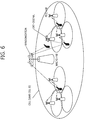
- FIG. 9 shows an example of a deployment scenario of CoMP scenario 3.
- CoMP scenario 3 may be referred to a heterogeneous network that has different cell IDs.
- the macro eNB provides a macro cell coverage.
- the macro eNB has cell ID #1.
- At least one pico eNB exists within the macro cell coverage.
- the pico eNB has cell ID #2. That is, the macro eNB and the pico eNB have different cell IDs.
- the CoMP UE may perform the CoMP transmission with the macro eNB and the pico eNB.
- FIG. 9 shows an example of the uplink CoMP transmission in which the CoMP UE transmits a signal to the macro eNB and the pico eNB.
- CoMP scenario 3 as shown in FIG. 9 , even in case the UL DMRS transmitted by each of the multiple UEs is transmitted through different bandwidth while being overlapped, high correlation among the UL RS sequences does not occur because the UL RS sequence is generated based on different cell IDs. That is, the UL RS transmitted by the multiple UEs are not orthogonal. However, if the CoMP UE performs the uplink CoMP transmission, the performance gain may be improved by the orthogonality of UL RS among cells. Accordingly, a method may be required to guarantee the orthogonality among the UL RSs which are transmitted by the multiple UEs even in CoMP scenario 3 as well.
- each of the multiple UEs transmits the UL RS through different bandwidth while being overlapped
- different cyclic shifts may be allocated to each UL RS.
- different OCCs may be allocated to each UE, additionally. That is, for the UL DMRS that is mapped to each single SC-FDMA symbol in two slots, different OCCs whose length are 2 may be applied to the UL DMRS of the different UEs respectively.
- the cyclic shift hopping pattern of the UL DMRS among the slots may be configured based on the existing cell ID. Or, the cyclic shift hopping among the slots of the UL DMRS may not be applied. Or, the group hopping and the sequence hopping among the slots of the UL DMRS may also not be applied.
- Each OCC corresponds to the OCC index.
- the OCC index which is allocated to each UE may be explicitly signaled through the PDCCH. That is, the OCC index may be signaled through the PDCCH with being added in the UL DCI format.
- the OCC index may be comprised of an additional 1 bit in the UL DCI format.
- the OCC index may be signaled through the RRC.
- the OCC index may be implicitly indicated. For example, similar to the method for multiplexing among the layers in the LTE rel-10, it may be indicated to allocate different OCCs to each UE by allocating different CSI indices.
- each transmission comb corresponds to the transmission comb index.
- the transmission comb index which is allocated to each UE may be explicitly signaled through the PDCCH. That is, the transmission comb index may be signaled through the PDCCH with being added in the UL DCI format. Or, the transmission comb index may be RRC signaled. Or, the transmission comb index may be implicitly indicated. For example, similar to the method for multiplexing among the SRS antenna ports in the LTE rel-10, it may be indicated to allocate different transmission combs by configuring the transmission comb according to the corresponding n SRS cs .
- Different OCCs may be allocated to each UL DMRS. That is, for the UL DMRS that is mapped to each single SC-FDMA symbol in two slots, different OCCs whose length are 2 may be applied to the UL DMRS of the different UEs respectively. In this time, the cyclic shift hopping of the UL DMRS among the slots may not be applied. Or, the group hopping and the sequence hopping among the slots of the UL DMRS may also not be applied.
- Each OCC corresponds to the OCC index.
- the OCC index which is allocated to each UE may be explicitly signaled through the PDCCH. That is, the OCC index may be signaled through the PDCCH with being added in the UL DCI format.
- the OCC index may be comprised of an additional 1 bit in the UL DCI format.
- the OCC index may be signaled through the RRC.
- the OCC index may be implicitly indicated. For example, similar to the method for multiplexing among the layers in the LTE rel-10, it may be indicated to allocate different OCCs each UE by allocating different CSI indices.
- the Disable-sequence-group-hopping parameter the UE-specific parameter
- the UE-specific parameter is set to enabled for the DMRS multiplexing among different UEs that belong to different nodes or different RRHs respectively. That is, it is assumed that the base sequence of the UL RS among the slots does not change.
- the group hopping or the sequence hopping being set not to be applied to the UL DMRS sequence that is allocated to each slot of the subframe, the UEs that belong to different nodes or different RRHs with one another may be multiplexed in DMRS based on the OCC.
- the description below is a mathematical analysis of the method for set up the group hopping, the sequence hopping and the cyclic shift hopping in order to guarantee the orthogonality of the RS among the cells.
- the first UL DMRS of the first UE which is allocated to the first RB (RB1) in the frequency domain may be represented by Equation 15 according to the slot.
- the second UL DMRS of the second UE which is allocated to the second RB (RB2) in the frequency domain may be represented by Equation 16 according to the slot.
- the receiving signal Y s1 in the first slot and the receiving signal Y s2 in the second slot may represented by Equation 17.
- Y s ⁇ 1 r UE 1 , s 1 + r UE 2
- s 1 Y s ⁇ 2 r UE 1 , s 2 + r UE 2 , s 2
- the receiving signal Y s1 in the first slot and the receiving signal Y s2 in the second slot may represented by Equation 18.
- the channel estimation of the second UE may be performed by using Equation 19.
- Equation 19 the channel estimation of the second UE is exemplified, but the channel estimation of the first UE may be performed in the same way.
- Equation 19 the orthogonality among UEs may be guaranteed if the RS interference term is 0.
- N RB1 N RB2 , that is, the bandwidths through which the first UL DMRS and the second UL DMRS are transmitted are the same.
- N RB1 N RB2 , that is, the bandwidth through which the first UL DMRS and the second UL DMRS are transmitted are the same.
- a method of identically setting up the cyclic shift hopping pattern among different cells may be considered in order to minimize the interference randomization and the inter-cell interference while maintaining the cyclic shift hopping mechanism defined in the legacy system, and to avoid the occurrence of high correlation among the UL DMRSs of different lengths which are transmitted through different bandwidths.
- the cyclic shift hopping pattern among the UEs, which belong to different cells may be set up identically by setting up the ⁇ ss with UE-specific, which is configured by the higher layer with cell-specific manner. Whether the ⁇ ss is allocated by the cell-specific manner as the existing method or by the UE-specific manner may be explicitly signaled by the RRC, or implicitly signaled.
- the RRC it is signaled whether it is possible to allocate the ⁇ ss with UE-specific by the RRC, and if possible, if may be explicitly signaled by the PDCCH whether the ⁇ ss is allocated by the cell-specific manner or by the UE-specific manner. That is, an indicator that indicates whether the ⁇ ss is allocated by the cell-specific manner or by the UE-specific manner may be included in the UL DCI format. Accordingly, the mutual compatibility is maintained between the legacy UE of the LTE rel-8/9/10 and so on, and the UE of the LTE real-11, and also, the performance deterioration of the existing legacy UE may be presented.
- N RB1 N RB2
- the bandwidths through which the first UL DMRS and the second UL DMRS are transmitted are the same.
- the n PN (n s ) which is used to determine the cyclic shift of the UL DMRS according to Equation 12 may be determined further based on a UE-specific parameter. That is, the n PN (n s ) may be determined according to the new equation in which a UE-specific parameter is added to Equation 13.
- the new equation in which a UE-specific parameter is added may have various forms.
- n PN (n s ) may be determined according to Equation 13 described above, the pseudo-random sequence generator may be initialized with c init (N ID cell , f ss PUSCH , X) at the beginning of each radio frame.
- X is a newly added UE-specific parameter.
- the conventional c init with which the pseudo-random sequence generator is initialized may be represented as the Equation 20 below.
- Equation 20 A UE-specific parameter may be added to Equation 20 according to the present invention.
- Equation 21 represents an example of the c init with which the pseudo-random sequence generator is initialized according to the present invention.
- the ⁇ CS_hopping is newly added UE-specific parameter.
- the ⁇ CS_hopping may have one value in the range of 0 to 29.
- Equation 22 below represents another example of the c init in with which the pseudo-random sequence generator is initialized according to the present invention.
- c init ⁇ N ID cell 30 ⁇ ⁇ 2 5 + f ss PUSCH + ⁇ CS_hopping mod 30
- the ⁇ CS_hopping is a newly added UE-specific parameter.
- the ⁇ CS_hopping may have one value in the range of 0 to 29.
- the cyclic shift hopping pattern may be generated by setting up the cell ID identically. That is, the cyclic shift hopping pattern may be generated by the virtual ID.
- the virtual ID of which purpose is to set up the cyclic shift hopping pattern identically may be signaled through the PDCCH. That is, the virtual ID may be signaled with being added in the UL DCI format. Or, the virtual ID may be signaled through the RRC. Or, whether it is possible to use the virtual ID may be signaled through the RRC, and if possible, an indicator to indicate it may be signaled through the PDCCH. Or, the virtual ID may be allocated through the RRC signaling, and whether it is possible to use the corresponding virtual ID may be signaled through the PDCCH. Accordingly, the mutual compatibility is maintained between the legacy UE and the UE of the LTE real-11, and, the performance deterioration of the existing legacy UE may be prevented.
- the macro eNB and the pico eNB may perform scheduling independently.
- the macro eNB and the pico eNB may divide the UEs independently by using the cell-specific parameter. If the corresponding information is not exchanged between the macro eNB and the pico eNB, whether the same group hopping, sequence hopping and cyclic shift hopping are applied among different UEs is not exactly acknowledged.
- the macro eNB and the pico eNB exchange the corresponding information through the X2 interface. Accordingly, even if the macro eNB and the pico eNB may perform scheduling independently, the orthogonality of the UL DMRS through the cyclic shift and/or the OCC may be guaranteed by using the exchanged corresponding information.
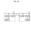
- FIG. 10 is a block diagram showing wireless communication system to implement an embodiment of the present invention.
- ABS 800 includes a processor 810, a memory 820, and a radio frequency (RF) unit 830.
- the processor 810 may be configured to implement proposed functions, procedures, and/or methods in this description. Layers of the radio interface protocol may be implemented in the processor 810.
- the memory 820 is operatively coupled with the processor 810 and stores a variety of information to operate the processor 810.
- the RF unit 830 is operatively coupled with the processor 810, and transmits and/or receives a radio signal.
- a UE 900 may include a processor 910, a memory 920 and a RF unit 930.
- the processor 910 may be configured to implement proposed functions, procedures and/or methods described in this description. Layers of the radio interface protocol may be implemented in the processor 910.
- the memory 920 is operatively coupled with the processor 910 and stores a variety of information to operate the processor 910.
- the RF unit 930 is operatively coupled with the processor 910, and transmits and/or receives a radio signal.
- the processors 810, 910 may include application-specific integrated circuit (ASIC), other chipset, logic circuit and/or data processing device.
- the memories 820, 920 may include read-only memory (ROM), random access memory (RAM), flash memory, memory card, storage medium and/or other storage device.
- the RF units 830, 930 may include baseband circuitry to process radio frequency signals.
- the techniques described herein can be implemented with modules (e.g., procedures, functions, and so on) that perform the functions described herein.
- the modules can be stored in memories 820, 920 and executed by processors 810, 910.
- the memories 820, 920 can be implemented within the processors 810, 910 or external to the processors 810, 910 in which case those can be communicatively coupled to the processors 810, 910 via various means as is known in the art.
Landscapes
- Engineering & Computer Science (AREA)
- Signal Processing (AREA)
- Computer Networks & Wireless Communication (AREA)
- Databases & Information Systems (AREA)
- Mobile Radio Communication Systems (AREA)
Applications Claiming Priority (10)
| Application Number | Priority Date | Filing Date | Title |
|---|---|---|---|
| US201161523856P | 2011-08-16 | 2011-08-16 | |
| US201161537064P | 2011-09-21 | 2011-09-21 | |
| US201161538149P | 2011-09-23 | 2011-09-23 | |
| US201161539999P | 2011-09-28 | 2011-09-28 | |
| US201161545580P | 2011-10-10 | 2011-10-10 | |
| US201161557388P | 2011-11-08 | 2011-11-08 | |
| US201161560246P | 2011-11-15 | 2011-11-15 | |
| US201161560814P | 2011-11-17 | 2011-11-17 | |
| US201161561233P | 2011-11-17 | 2011-11-17 | |
| PCT/KR2012/006508 WO2013025054A2 (ko) | 2011-08-16 | 2012-08-16 | 무선 통신 시스템에서 상향링크 참조 신호 전송 방법 및 장치 |
Publications (3)
| Publication Number | Publication Date |
|---|---|
| EP2747320A2 true EP2747320A2 (de) | 2014-06-25 |
| EP2747320A4 EP2747320A4 (de) | 2015-03-18 |
| EP2747320B1 EP2747320B1 (de) | 2016-09-28 |
Family
ID=47715599
Family Applications (1)
| Application Number | Title | Priority Date | Filing Date |
|---|---|---|---|
| EP12824600.6A Active EP2747320B1 (de) | 2011-08-16 | 2012-08-16 | Verfahren und vorrichtung zur übertragung von uplink-referenzsignalen in einem drahtlosen kommunikationssystem |
Country Status (6)
| Country | Link |
|---|---|
| US (2) | US9497734B2 (de) |
| EP (1) | EP2747320B1 (de) |
| JP (1) | JP5781694B2 (de) |
| KR (1) | KR101572397B1 (de) |
| CN (1) | CN103858368B (de) |
| WO (1) | WO2013025054A2 (de) |
Cited By (6)
| Publication number | Priority date | Publication date | Assignee | Title |
|---|---|---|---|---|
| EP2983431A1 (de) * | 2013-04-05 | 2016-02-10 | Ntt Docomo, Inc. | Benutzerendgerät, kleine basisstation und kommunikationsverfahren |
| WO2017061930A1 (en) * | 2015-10-05 | 2017-04-13 | Telefonaktiebolaget Lm Ericsson (Publ) | Methods, network nodes and devices for communicating at an unlicensed frequency spectrum |
| WO2019114710A1 (zh) * | 2017-12-11 | 2019-06-20 | 中兴通讯股份有限公司 | 参考信号的传输方法及装置 |
| EP3522476A4 (de) * | 2016-11-03 | 2020-01-15 | Huawei Technologies Co., Ltd. | Verfahren und vorrichtung zum konfigurieren eines referenzsignals |
| CN110868240A (zh) * | 2018-08-08 | 2020-03-06 | 维沃移动通信有限公司 | Pusch重复传输时的跳频方法、终端及网络设备 |
| US11632283B2 (en) | 2016-11-04 | 2023-04-18 | Telefonaktiebolaget Lm Ericsson (Publ) | Signaling of demodulation reference signal configuration for uplink short TTI transmissions |
Families Citing this family (41)
| Publication number | Priority date | Publication date | Assignee | Title |
|---|---|---|---|---|
| US8953478B2 (en) | 2012-01-27 | 2015-02-10 | Intel Corporation | Evolved node B and method for coherent coordinated multipoint transmission with per CSI-RS feedback |
| US9155089B2 (en) * | 2012-08-10 | 2015-10-06 | Qualcomm Incorporated | Cell ID and antenna port configurations for EPDCCH |
| EP3185606B1 (de) * | 2012-08-13 | 2019-10-09 | Huawei Technologies Co., Ltd. | Verfahren und vorrichtung für koordinierte übertragungen |
| JP6152253B2 (ja) * | 2012-08-29 | 2017-06-21 | 株式会社Nttドコモ | 無線基地局 |
| US10085247B2 (en) * | 2013-03-08 | 2018-09-25 | Sharp Kabushiki Kaisha | Physical control channel monitoring |
| EP2975783B1 (de) * | 2013-03-13 | 2017-10-11 | LG Electronics Inc. | Verfahren zur quittierung von in der aufwärtsstrecke übertragenen nachrichten und vorrichtung dafür |
| CN104363974A (zh) * | 2013-03-20 | 2015-02-18 | 华为技术有限公司 | 用户设备冲突检测方法、用户设备和基站 |
| KR102094419B1 (ko) * | 2013-07-11 | 2020-03-27 | 주식회사 팬택 | 무선 통신 시스템에서 참조 신호를 전송하는 방법 및 장치 |
| WO2015076712A1 (en) * | 2013-11-20 | 2015-05-28 | Telefonaktiebolaget L M Ericsson (Publ) | Dynamic dm-rs sequence selection by pql indicator |
| US11743897B2 (en) * | 2013-12-20 | 2023-08-29 | Qualcomm Incorporated | Techniques for configuring uplink channels in unlicensed radio frequency spectrum bands |
| WO2015103788A1 (zh) * | 2014-01-13 | 2015-07-16 | 华为终端有限公司 | 传输参考信号的方法和用户设备 |
| WO2016052980A1 (ko) * | 2014-09-30 | 2016-04-07 | 엘지전자 주식회사 | Fdr 전송을 지원하는 무선 통신 시스템에서 디바이스 간 간섭을 측정하는 방법 및 이를 위한 장치 |
| KR102287875B1 (ko) | 2015-04-17 | 2021-08-09 | 삼성전자주식회사 | 무선 통신 시스템에서 기준 신호들을 송신하기 위한 장치 및 방법 |
| PL3767906T3 (pl) * | 2015-09-25 | 2023-03-20 | Innovative Technology Lab Co., Ltd. | Aparat do konfiguracji DM-RS dla V2X |
| KR102058718B1 (ko) | 2016-02-02 | 2020-01-22 | 엘지전자 주식회사 | 상향링크 제어 채널 전송 방법 및 이를 수행하는 사용자 장치 |
| US20170237592A1 (en) * | 2016-02-05 | 2017-08-17 | Mediatek Inc. | Peak to average power ratio reduction in elaa |
| CN108604967B (zh) * | 2016-02-25 | 2021-07-23 | 苹果公司 | 对非调度上行链路传输的传输检测 |
| US20180062801A1 (en) * | 2016-08-24 | 2018-03-01 | Qualcomm Incorporated | Techniques for wireless communications in coordinated multi-point operation |
| WO2018058555A1 (en) * | 2016-09-30 | 2018-04-05 | Qualcomm Incorporated | Comb adaptation for interlaced fdm dmrs |
| CN108270711B (zh) * | 2017-01-04 | 2021-12-03 | 华为技术有限公司 | 传输参考信号的方法、设备和系统 |
| KR102280730B1 (ko) * | 2017-01-05 | 2021-07-23 | 닛본 덴끼 가부시끼가이샤 | 기준 신호 송신 및 수신을 위한 방법 및 장치 |
| US10187782B2 (en) * | 2017-02-28 | 2019-01-22 | Harris Corporation | Passive identification of BTS serving mobile units |
| US10568055B2 (en) * | 2017-03-03 | 2020-02-18 | Motorola Mobility Llc | Method and apparatus for communicating synchronization signals |
| JP2017147769A (ja) * | 2017-06-05 | 2017-08-24 | 株式会社Nttドコモ | ユーザ端末、無線通信方法及び移動通信システム |
| CN110622457B (zh) * | 2017-06-12 | 2022-06-07 | 苹果公司 | 探测参考信号序列设计 |
| JP6710812B2 (ja) | 2017-06-16 | 2020-06-17 | エルジー エレクトロニクス インコーポレイティド | 無線通信システムにおいて端末と基地局の間の物理上りリンク制御チャネルを送受信する方法及びそれを支援する装置 |
| CN109150447B (zh) * | 2017-06-16 | 2022-09-27 | 中兴通讯股份有限公司 | 信息发送、数据解调方法及装置、通信节点、网络侧设备 |
| JPWO2018235299A1 (ja) * | 2017-06-23 | 2020-04-23 | 株式会社Nttドコモ | ユーザ端末及び無線通信方法 |
| KR102404611B1 (ko) * | 2017-11-10 | 2022-05-31 | 지티이 코포레이션 | 짧은 시퀀스 신호의 그룹화 및 사용 |
| WO2019098712A1 (ko) * | 2017-11-16 | 2019-05-23 | 엘지전자 주식회사 | Srs를 전송 및 수신하는 방법과 이를 위한 통신 장치 |
| CN109818895B (zh) * | 2017-11-17 | 2022-04-29 | 中兴通讯股份有限公司 | 确定序列组的方法及装置,确定循环移位的方法及装置 |
| CN114826536A (zh) * | 2017-12-29 | 2022-07-29 | 中兴通讯股份有限公司 | 测量参考信号的传输方法及装置 |
| AU2018402112B2 (en) * | 2018-01-11 | 2024-05-09 | Ntt Docomo, Inc. | User terminal and radio communication method |
| CN108260219B (zh) | 2018-01-12 | 2021-11-12 | 中兴通讯股份有限公司 | 一种参考信号的接收和发送方法、设备及计算机可读存储介质 |
| CN109302272B (zh) * | 2018-02-13 | 2022-06-03 | 中兴通讯股份有限公司 | Csi报告的发送、接收方法及装置、电子装置 |
| CA3090946A1 (en) * | 2018-02-16 | 2019-08-22 | Ntt Docomo, Inc. | User terminal and radio communication method |
| KR102027931B1 (ko) | 2018-06-22 | 2019-10-02 | 주식회사 명신메디칼 | 발열 저감을 갖는 면상발열체 |
| KR101960279B1 (ko) | 2018-06-22 | 2019-03-20 | 주식회사 명신메디칼 | 발열 저감을 갖는 면상발열체의 제조방법 및 이로부터 제조된 면상발열체 |
| EP3864791A4 (de) * | 2018-10-08 | 2022-07-06 | INTEL Corporation | Sequenzdesign von demodulationsreferenzsignalen (dmrs) mit niedrigem spitzenleistung-zu mittelleistung-verhältnis (papr) für uplink |
| CN110224737B (zh) * | 2019-05-20 | 2020-08-11 | 南京控维通信科技有限公司 | 面向卫星应急通信系统的多级网控中心实现方法 |
| US20230018270A1 (en) * | 2019-12-20 | 2023-01-19 | Ntt Docomo, Inc. | Terminal and radio communication method |
Family Cites Families (38)
| Publication number | Priority date | Publication date | Assignee | Title |
|---|---|---|---|---|
| JP4601637B2 (ja) * | 2007-03-20 | 2010-12-22 | 株式会社エヌ・ティ・ティ・ドコモ | 移動局、送信方法及び無線通信システム |
| TW200918545A (en) * | 2007-06-20 | 2009-05-01 | Sumitomo Chemical Co | Bipyridine compound, transition metal complex, and method for production of conjugated aromatic compound using the transition metal complex |
| KR100940730B1 (ko) * | 2007-09-07 | 2010-02-04 | 엘지전자 주식회사 | 무선통신 시스템에서 기준 신호 생성 방법 |
| US8077693B2 (en) * | 2007-09-19 | 2011-12-13 | Samsung Electronics Co., Ltd. | Resource remapping and regrouping in a wireless communication system |
| KR101625861B1 (ko) * | 2008-07-22 | 2016-06-01 | 엘지전자 주식회사 | 상향링크 전송 시, 다중 코드워드 기반 단일 사용자 mimo가 사용되는 시스템에 있어서, phich 할당 및 참조 신호 생성 방법 |
| WO2010073468A1 (ja) | 2008-12-26 | 2010-07-01 | シャープ株式会社 | 基地局装置、移動局装置、通信システム及び通信方法 |
| CN101777941B (zh) * | 2009-01-12 | 2014-10-08 | 华为技术有限公司 | 协作多点传输系统中的下行传输方法、网络设备和无线系统 |
| US20100189038A1 (en) * | 2009-01-23 | 2010-07-29 | Runhua Chen | Circuit and method for mapping data symbols and reference signals for coordinated multi-point systems |
| KR101478316B1 (ko) | 2009-04-28 | 2014-12-31 | 한국전자통신연구원 | 전용 레퍼런스 시그널 전송 방법 및 전용 레퍼런스 시그널 수신 방법 |
| US9705653B2 (en) * | 2009-05-04 | 2017-07-11 | Qualcomm Inc. | Downlink control transmission in multicarrier operation |
| US20110142107A1 (en) | 2009-06-16 | 2011-06-16 | Kyle Jung-Lin Pan | Rank Adaptive Cyclic Shift for Demodulation Reference Signal |
| US8842623B2 (en) | 2009-06-26 | 2014-09-23 | Lg Electronics Inc. | Method and apparatus for transmitting reference signals in uplink multiple input multiple output (MIMO) transmission |
| CN101965004A (zh) * | 2009-07-21 | 2011-02-02 | 中兴通讯股份有限公司 | 一种用户终端归属节点的选择方法及系统 |
| US8902849B2 (en) * | 2009-09-16 | 2014-12-02 | Lg Electronics Inc. | Method and apparatus for transmitting a reference signal in a multi-antenna system |
| JP2013505622A (ja) * | 2009-09-16 | 2013-02-14 | エルジー エレクトロニクス インコーポレイティド | 多重アンテナシステムにおける参照信号送信方法及び装置 |
| CN102026298B (zh) * | 2009-09-22 | 2014-04-30 | 中兴通讯股份有限公司 | 消除多点协作中不同小区用户间srs干扰的方法与系统 |
| US8923905B2 (en) * | 2009-09-30 | 2014-12-30 | Qualcomm Incorporated | Scrambling sequence initialization for coordinated multi-point transmissions |
| US8634362B2 (en) * | 2009-10-01 | 2014-01-21 | Qualcomm Incorporated | Reference signals for multi-user MIMO communication |
| US8908617B2 (en) * | 2009-12-31 | 2014-12-09 | Samsung Electronics Co., Ltd. | Uplink demodulation reference signal design for MIMO transmission |
| CN102687454B (zh) * | 2010-01-08 | 2015-09-30 | 诺基亚通信公司 | 用于在无线通信中使用解调参考信号复用的方法和设备 |
| US8305987B2 (en) * | 2010-02-12 | 2012-11-06 | Research In Motion Limited | Reference signal for a coordinated multi-point network implementation |
| EP2375618A1 (de) * | 2010-04-08 | 2011-10-12 | HTC Corporation | Verfahren zur Verwaltung der Übertragung eines Referenzsignals zur Kanalmessung |
| US20110267948A1 (en) * | 2010-05-03 | 2011-11-03 | Koc Ali T | Techniques for communicating and managing congestion in a wireless network |
| KR101699493B1 (ko) * | 2010-05-03 | 2017-01-26 | 주식회사 팬택 | Mimo 환경에서 직교성을 제공하는 사이클릭 쉬프트 파라메터를 송수신하는 방법 및 장치 |
| CN102238641A (zh) * | 2010-05-06 | 2011-11-09 | 宏达国际电子股份有限公司 | 处理上行链路控制通道的方法及其通信装置 |
| WO2012076043A1 (en) * | 2010-12-08 | 2012-06-14 | Nokia Siemens Networks Oy | Resource allocation in a wireless communication system |
| CN103931253B (zh) * | 2011-05-03 | 2018-07-31 | 诺基亚通信公司 | 用于在混合小区标识符场景中动态分配标识符的方法和设备 |
| KR101840642B1 (ko) * | 2011-06-07 | 2018-03-21 | 한국전자통신연구원 | 분산 안테나 무선 통신 시스템 및 그 방법 |
| JP2013017016A (ja) * | 2011-07-04 | 2013-01-24 | Sharp Corp | 基地局装置、移動局装置、通信システムおよび通信方法 |
| CN103703734B (zh) * | 2011-07-27 | 2019-03-19 | Lg电子株式会社 | 在多节点系统中发送上行链路参考信号的方法和使用该方法的终端 |
| US8995385B2 (en) * | 2011-08-05 | 2015-03-31 | Samsung Electronics Co., Ltd. | Apparatus and method for UE-specific demodulation reference signal scrambling |
| US8693420B2 (en) * | 2011-08-10 | 2014-04-08 | Futurewei Technologies, Inc. | System and method for signaling and transmitting uplink reference signals |
| US9337984B2 (en) * | 2011-08-19 | 2016-05-10 | Lg Electronics Inc. | Method for transmitting uplink control information, user equipment, method for receiving uplink control information, and base station |
| KR101901942B1 (ko) * | 2011-11-17 | 2018-09-28 | 엘지전자 주식회사 | 상향링크 신호 수신 방법 및 기지국과, 상향링크 신호 전송 방법 및 사용자기기 |
| US8953478B2 (en) * | 2012-01-27 | 2015-02-10 | Intel Corporation | Evolved node B and method for coherent coordinated multipoint transmission with per CSI-RS feedback |
| US9509461B2 (en) * | 2012-02-20 | 2016-11-29 | Lg Electronics Inc. | Method and apparatus for transmitting and receiving signals in wireless communication system |
| CN102646117B (zh) * | 2012-02-20 | 2015-07-08 | 华为技术有限公司 | 文件数据传送的方法与装置 |
| US9107223B2 (en) * | 2012-05-23 | 2015-08-11 | Telefonaktiebolaget L M Ericsson (Publ) | Methods, systems and devices for decoupled interference randomization for uplink reference signals |
-
2012
- 2012-08-16 EP EP12824600.6A patent/EP2747320B1/de active Active
- 2012-08-16 CN CN201280050460.4A patent/CN103858368B/zh active Active
- 2012-08-16 KR KR1020147004254A patent/KR101572397B1/ko active IP Right Grant
- 2012-08-16 WO PCT/KR2012/006508 patent/WO2013025054A2/ko active Application Filing
- 2012-08-16 JP JP2014524952A patent/JP5781694B2/ja active Active
- 2012-08-16 US US14/239,010 patent/US9497734B2/en active Active
-
2016
- 2016-10-05 US US15/286,166 patent/US10412715B2/en active Active
Cited By (13)
| Publication number | Priority date | Publication date | Assignee | Title |
|---|---|---|---|---|
| EP2983431A4 (de) * | 2013-04-05 | 2016-11-09 | Ntt Docomo Inc | Benutzerendgerät, kleine basisstation und kommunikationsverfahren |
| EP2983431A1 (de) * | 2013-04-05 | 2016-02-10 | Ntt Docomo, Inc. | Benutzerendgerät, kleine basisstation und kommunikationsverfahren |
| EP3914023A1 (de) * | 2015-10-05 | 2021-11-24 | Telefonaktiebolaget LM Ericsson (publ) | Verfahren, netzwerkknoten und vorrichtungen zur kommunikation in einem unlizenzierten frequenzspektrum |
| WO2017061930A1 (en) * | 2015-10-05 | 2017-04-13 | Telefonaktiebolaget Lm Ericsson (Publ) | Methods, network nodes and devices for communicating at an unlicensed frequency spectrum |
| US11523426B2 (en) | 2015-10-05 | 2022-12-06 | Telefonaktiebolaget Lm Ericsson (Publ) | Methods, network nodes and devices for communicating at an unlicensed frequency spectrum |
| US10932291B2 (en) | 2015-10-05 | 2021-02-23 | Telefonaktiebolaget Lm Ericsson (Publ) | Methods, network nodes and devices for communicating at an unlicensed frequency spectrum |
| EP3522476A4 (de) * | 2016-11-03 | 2020-01-15 | Huawei Technologies Co., Ltd. | Verfahren und vorrichtung zum konfigurieren eines referenzsignals |
| US11632283B2 (en) | 2016-11-04 | 2023-04-18 | Telefonaktiebolaget Lm Ericsson (Publ) | Signaling of demodulation reference signal configuration for uplink short TTI transmissions |
| US10693611B2 (en) | 2017-12-11 | 2020-06-23 | Zte Corporation | Method and apparatus for transmitting a reference signal |
| US11463220B2 (en) | 2017-12-11 | 2022-10-04 | Zte Corporation | Method and apparatus for transmitting a reference signal |
| WO2019114710A1 (zh) * | 2017-12-11 | 2019-06-20 | 中兴通讯股份有限公司 | 参考信号的传输方法及装置 |
| US11916834B2 (en) | 2017-12-11 | 2024-02-27 | Zte Corporation | Method and apparatus for transmitting a reference signal |
| CN110868240A (zh) * | 2018-08-08 | 2020-03-06 | 维沃移动通信有限公司 | Pusch重复传输时的跳频方法、终端及网络设备 |
Also Published As
| Publication number | Publication date |
|---|---|
| WO2013025054A2 (ko) | 2013-02-21 |
| US20170026955A1 (en) | 2017-01-26 |
| US10412715B2 (en) | 2019-09-10 |
| US9497734B2 (en) | 2016-11-15 |
| JP2014527354A (ja) | 2014-10-09 |
| CN103858368A (zh) | 2014-06-11 |
| JP5781694B2 (ja) | 2015-09-24 |
| CN103858368B (zh) | 2017-04-12 |
| KR101572397B1 (ko) | 2015-11-26 |
| KR20140044393A (ko) | 2014-04-14 |
| WO2013025054A3 (ko) | 2013-04-11 |
| EP2747320A4 (de) | 2015-03-18 |
| US20140211736A1 (en) | 2014-07-31 |
| EP2747320B1 (de) | 2016-09-28 |
Similar Documents
| Publication | Publication Date | Title |
|---|---|---|
| US10412715B2 (en) | Method and apparatus for transmitting uplink reference signal in wireless communication system | |
| US11395281B2 (en) | Method and apparatus for transmitting reference signal in wireless communication system | |
| US9843466B2 (en) | Method and apparatus for generating an uplink reference signal sequence in a wireless communication system | |
| US10069610B2 (en) | Method and apparatus for generating a reference signal sequence in a wireless communication system | |
| US8923250B2 (en) | Method and apparatus for mapping a plurality of layers to a plurality of antenna ports in a wireless communication system | |
| US9048976B2 (en) | Apparatus and method for transmitting reference signals in wireless communication system | |
| US9374833B2 (en) | Method and device for exchanging data in wireless communication system | |
| WO2010117240A2 (en) | Method and apparatus for transmitting reference signal in wireless communication system | |
| WO2011034317A2 (en) | Method and apparatus for transmitting reference signal in time division duplex system | |
| US9264262B2 (en) | Method and apparatus for transmitting aperiodic sounding reference signal in wireless communication system |
Legal Events
| Date | Code | Title | Description |
|---|---|---|---|
| PUAI | Public reference made under article 153(3) epc to a published international application that has entered the european phase |
Free format text: ORIGINAL CODE: 0009012 |
|
| 17P | Request for examination filed |
Effective date: 20140205 |
|
| AK | Designated contracting states |
Kind code of ref document: A2 Designated state(s): AL AT BE BG CH CY CZ DE DK EE ES FI FR GB GR HR HU IE IS IT LI LT LU LV MC MK MT NL NO PL PT RO RS SE SI SK SM TR |
|
| DAX | Request for extension of the european patent (deleted) | ||
| A4 | Supplementary search report drawn up and despatched |
Effective date: 20150216 |
|
| RIC1 | Information provided on ipc code assigned before grant |
Ipc: H04L 5/00 20060101ALN20150210BHEP Ipc: H04J 11/00 20060101AFI20150210BHEP Ipc: H04B 7/26 20060101ALI20150210BHEP |
|
| 17Q | First examination report despatched |
Effective date: 20151029 |
|
| GRAP | Despatch of communication of intention to grant a patent |
Free format text: ORIGINAL CODE: EPIDOSNIGR1 |
|
| RIC1 | Information provided on ipc code assigned before grant |
Ipc: H04L 27/26 20060101ALI20160315BHEP Ipc: H04L 5/00 20060101ALN20160315BHEP Ipc: H04W 56/00 20090101ALI20160315BHEP Ipc: H04J 11/00 20060101AFI20160315BHEP Ipc: H04B 7/02 20060101ALN20160315BHEP Ipc: H04B 7/26 20060101ALI20160315BHEP |
|
| INTG | Intention to grant announced |
Effective date: 20160406 |
|
| RAP1 | Party data changed (applicant data changed or rights of an application transferred) |
Owner name: LG ELECTRONICS INC. |
|
| GRAS | Grant fee paid |
Free format text: ORIGINAL CODE: EPIDOSNIGR3 |
|
| GRAA | (expected) grant |
Free format text: ORIGINAL CODE: 0009210 |
|
| AK | Designated contracting states |
Kind code of ref document: B1 Designated state(s): AL AT BE BG CH CY CZ DE DK EE ES FI FR GB GR HR HU IE IS IT LI LT LU LV MC MK MT NL NO PL PT RO RS SE SI SK SM TR |
|
| REG | Reference to a national code |
Ref country code: GB Ref legal event code: FG4D |
|
| REG | Reference to a national code |
Ref country code: CH Ref legal event code: EP |
|
| REG | Reference to a national code |
Ref country code: AT Ref legal event code: REF Ref document number: 833537 Country of ref document: AT Kind code of ref document: T Effective date: 20161015 |
|
| REG | Reference to a national code |
Ref country code: NL Ref legal event code: FP |
|
| REG | Reference to a national code |
Ref country code: IE Ref legal event code: FG4D |
|
| REG | Reference to a national code |
Ref country code: DE Ref legal event code: R096 Ref document number: 602012023598 Country of ref document: DE |
|
| REG | Reference to a national code |
Ref country code: SE Ref legal event code: TRGR |
|
| REG | Reference to a national code |
Ref country code: LT Ref legal event code: MG4D |
|
| PG25 | Lapsed in a contracting state [announced via postgrant information from national office to epo] |
Ref country code: NO Free format text: LAPSE BECAUSE OF FAILURE TO SUBMIT A TRANSLATION OF THE DESCRIPTION OR TO PAY THE FEE WITHIN THE PRESCRIBED TIME-LIMIT Effective date: 20161228 Ref country code: LT Free format text: LAPSE BECAUSE OF FAILURE TO SUBMIT A TRANSLATION OF THE DESCRIPTION OR TO PAY THE FEE WITHIN THE PRESCRIBED TIME-LIMIT Effective date: 20160928 Ref country code: HR Free format text: LAPSE BECAUSE OF FAILURE TO SUBMIT A TRANSLATION OF THE DESCRIPTION OR TO PAY THE FEE WITHIN THE PRESCRIBED TIME-LIMIT Effective date: 20160928 Ref country code: RS Free format text: LAPSE BECAUSE OF FAILURE TO SUBMIT A TRANSLATION OF THE DESCRIPTION OR TO PAY THE FEE WITHIN THE PRESCRIBED TIME-LIMIT Effective date: 20160928 |
|
| REG | Reference to a national code |
Ref country code: AT Ref legal event code: MK05 Ref document number: 833537 Country of ref document: AT Kind code of ref document: T Effective date: 20160928 |
|
| PG25 | Lapsed in a contracting state [announced via postgrant information from national office to epo] |
Ref country code: LV Free format text: LAPSE BECAUSE OF FAILURE TO SUBMIT A TRANSLATION OF THE DESCRIPTION OR TO PAY THE FEE WITHIN THE PRESCRIBED TIME-LIMIT Effective date: 20160928 Ref country code: GR Free format text: LAPSE BECAUSE OF FAILURE TO SUBMIT A TRANSLATION OF THE DESCRIPTION OR TO PAY THE FEE WITHIN THE PRESCRIBED TIME-LIMIT Effective date: 20161229 |
|
| PG25 | Lapsed in a contracting state [announced via postgrant information from national office to epo] |
Ref country code: EE Free format text: LAPSE BECAUSE OF FAILURE TO SUBMIT A TRANSLATION OF THE DESCRIPTION OR TO PAY THE FEE WITHIN THE PRESCRIBED TIME-LIMIT Effective date: 20160928 Ref country code: RO Free format text: LAPSE BECAUSE OF FAILURE TO SUBMIT A TRANSLATION OF THE DESCRIPTION OR TO PAY THE FEE WITHIN THE PRESCRIBED TIME-LIMIT Effective date: 20160928 |
|
| PG25 | Lapsed in a contracting state [announced via postgrant information from national office to epo] |
Ref country code: IS Free format text: LAPSE BECAUSE OF FAILURE TO SUBMIT A TRANSLATION OF THE DESCRIPTION OR TO PAY THE FEE WITHIN THE PRESCRIBED TIME-LIMIT Effective date: 20170128 Ref country code: CZ Free format text: LAPSE BECAUSE OF FAILURE TO SUBMIT A TRANSLATION OF THE DESCRIPTION OR TO PAY THE FEE WITHIN THE PRESCRIBED TIME-LIMIT Effective date: 20160928 Ref country code: BG Free format text: LAPSE BECAUSE OF FAILURE TO SUBMIT A TRANSLATION OF THE DESCRIPTION OR TO PAY THE FEE WITHIN THE PRESCRIBED TIME-LIMIT Effective date: 20161228 Ref country code: ES Free format text: LAPSE BECAUSE OF FAILURE TO SUBMIT A TRANSLATION OF THE DESCRIPTION OR TO PAY THE FEE WITHIN THE PRESCRIBED TIME-LIMIT Effective date: 20160928 Ref country code: SM Free format text: LAPSE BECAUSE OF FAILURE TO SUBMIT A TRANSLATION OF THE DESCRIPTION OR TO PAY THE FEE WITHIN THE PRESCRIBED TIME-LIMIT Effective date: 20160928 Ref country code: AT Free format text: LAPSE BECAUSE OF FAILURE TO SUBMIT A TRANSLATION OF THE DESCRIPTION OR TO PAY THE FEE WITHIN THE PRESCRIBED TIME-LIMIT Effective date: 20160928 Ref country code: BE Free format text: LAPSE BECAUSE OF FAILURE TO SUBMIT A TRANSLATION OF THE DESCRIPTION OR TO PAY THE FEE WITHIN THE PRESCRIBED TIME-LIMIT Effective date: 20160928 Ref country code: PL Free format text: LAPSE BECAUSE OF FAILURE TO SUBMIT A TRANSLATION OF THE DESCRIPTION OR TO PAY THE FEE WITHIN THE PRESCRIBED TIME-LIMIT Effective date: 20160928 Ref country code: PT Free format text: LAPSE BECAUSE OF FAILURE TO SUBMIT A TRANSLATION OF THE DESCRIPTION OR TO PAY THE FEE WITHIN THE PRESCRIBED TIME-LIMIT Effective date: 20170130 Ref country code: SK Free format text: LAPSE BECAUSE OF FAILURE TO SUBMIT A TRANSLATION OF THE DESCRIPTION OR TO PAY THE FEE WITHIN THE PRESCRIBED TIME-LIMIT Effective date: 20160928 |
|
| REG | Reference to a national code |
Ref country code: DE Ref legal event code: R097 Ref document number: 602012023598 Country of ref document: DE |
|
| REG | Reference to a national code |
Ref country code: FR Ref legal event code: PLFP Year of fee payment: 6 |
|
| PG25 | Lapsed in a contracting state [announced via postgrant information from national office to epo] |
Ref country code: DK Free format text: LAPSE BECAUSE OF FAILURE TO SUBMIT A TRANSLATION OF THE DESCRIPTION OR TO PAY THE FEE WITHIN THE PRESCRIBED TIME-LIMIT Effective date: 20160928 |
|
| PLBE | No opposition filed within time limit |
Free format text: ORIGINAL CODE: 0009261 |
|
| STAA | Information on the status of an ep patent application or granted ep patent |
Free format text: STATUS: NO OPPOSITION FILED WITHIN TIME LIMIT |
|
| 26N | No opposition filed |
Effective date: 20170629 |
|
| PG25 | Lapsed in a contracting state [announced via postgrant information from national office to epo] |
Ref country code: SI Free format text: LAPSE BECAUSE OF FAILURE TO SUBMIT A TRANSLATION OF THE DESCRIPTION OR TO PAY THE FEE WITHIN THE PRESCRIBED TIME-LIMIT Effective date: 20160928 |
|
| REG | Reference to a national code |
Ref country code: CH Ref legal event code: PL |
|
| PG25 | Lapsed in a contracting state [announced via postgrant information from national office to epo] |
Ref country code: MC Free format text: LAPSE BECAUSE OF FAILURE TO SUBMIT A TRANSLATION OF THE DESCRIPTION OR TO PAY THE FEE WITHIN THE PRESCRIBED TIME-LIMIT Effective date: 20160928 |
|
| PG25 | Lapsed in a contracting state [announced via postgrant information from national office to epo] |
Ref country code: LI Free format text: LAPSE BECAUSE OF NON-PAYMENT OF DUE FEES Effective date: 20170831 Ref country code: CH Free format text: LAPSE BECAUSE OF NON-PAYMENT OF DUE FEES Effective date: 20170831 |
|
| REG | Reference to a national code |
Ref country code: IE Ref legal event code: MM4A |
|
| PG25 | Lapsed in a contracting state [announced via postgrant information from national office to epo] |
Ref country code: LU Free format text: LAPSE BECAUSE OF NON-PAYMENT OF DUE FEES Effective date: 20170816 |
|
| REG | Reference to a national code |
Ref country code: FR Ref legal event code: PLFP Year of fee payment: 7 |
|
| PG25 | Lapsed in a contracting state [announced via postgrant information from national office to epo] |
Ref country code: IE Free format text: LAPSE BECAUSE OF NON-PAYMENT OF DUE FEES Effective date: 20170816 |
|
| PG25 | Lapsed in a contracting state [announced via postgrant information from national office to epo] |
Ref country code: MT Free format text: LAPSE BECAUSE OF NON-PAYMENT OF DUE FEES Effective date: 20170816 |
|
| PG25 | Lapsed in a contracting state [announced via postgrant information from national office to epo] |
Ref country code: AL Free format text: LAPSE BECAUSE OF FAILURE TO SUBMIT A TRANSLATION OF THE DESCRIPTION OR TO PAY THE FEE WITHIN THE PRESCRIBED TIME-LIMIT Effective date: 20160928 |
|
| PG25 | Lapsed in a contracting state [announced via postgrant information from national office to epo] |
Ref country code: HU Free format text: LAPSE BECAUSE OF FAILURE TO SUBMIT A TRANSLATION OF THE DESCRIPTION OR TO PAY THE FEE WITHIN THE PRESCRIBED TIME-LIMIT; INVALID AB INITIO Effective date: 20120816 |
|
| PG25 | Lapsed in a contracting state [announced via postgrant information from national office to epo] |
Ref country code: CY Free format text: LAPSE BECAUSE OF NON-PAYMENT OF DUE FEES Effective date: 20160928 |
|
| PG25 | Lapsed in a contracting state [announced via postgrant information from national office to epo] |
Ref country code: MK Free format text: LAPSE BECAUSE OF FAILURE TO SUBMIT A TRANSLATION OF THE DESCRIPTION OR TO PAY THE FEE WITHIN THE PRESCRIBED TIME-LIMIT Effective date: 20160928 |
|
| REG | Reference to a national code |
Ref country code: GB Ref legal event code: 732E Free format text: REGISTERED BETWEEN 20191212 AND 20191218 |
|
| REG | Reference to a national code |
Ref country code: NL Ref legal event code: PD Owner name: QUALCOMM INCORPORATED; US Free format text: DETAILS ASSIGNMENT: CHANGE OF OWNER(S), ASSIGNMENT; FORMER OWNER NAME: LG ELECTRONICS INC. Effective date: 20200107 |
|
| REG | Reference to a national code |
Ref country code: DE Ref legal event code: R082 Ref document number: 602012023598 Country of ref document: DE Representative=s name: MAUCHER JENKINS PATENTANWAELTE & RECHTSANWAELT, DE Ref country code: DE Ref legal event code: R081 Ref document number: 602012023598 Country of ref document: DE Owner name: QUALCOMM INCORPORATED (N.D. GES. D. STAATES DE, US Free format text: FORMER OWNER: LG ELECTRONICS INC., SEOUL, KR |
|
| PG25 | Lapsed in a contracting state [announced via postgrant information from national office to epo] |
Ref country code: TR Free format text: LAPSE BECAUSE OF FAILURE TO SUBMIT A TRANSLATION OF THE DESCRIPTION OR TO PAY THE FEE WITHIN THE PRESCRIBED TIME-LIMIT Effective date: 20160928 |
|
| PGFP | Annual fee paid to national office [announced via postgrant information from national office to epo] |
Ref country code: IT Payment date: 20230810 Year of fee payment: 12 Ref country code: GB Payment date: 20230712 Year of fee payment: 12 Ref country code: FI Payment date: 20230727 Year of fee payment: 12 |
|
| PGFP | Annual fee paid to national office [announced via postgrant information from national office to epo] |
Ref country code: SE Payment date: 20230808 Year of fee payment: 12 Ref country code: FR Payment date: 20230710 Year of fee payment: 12 Ref country code: DE Payment date: 20230425 Year of fee payment: 12 |
|
| PGFP | Annual fee paid to national office [announced via postgrant information from national office to epo] |
Ref country code: NL Payment date: 20240711 Year of fee payment: 13 |