EP2747213A1 - Adapteranordnung - Google Patents
Adapteranordnung Download PDFInfo
- Publication number
- EP2747213A1 EP2747213A1 EP20130195444 EP13195444A EP2747213A1 EP 2747213 A1 EP2747213 A1 EP 2747213A1 EP 20130195444 EP20130195444 EP 20130195444 EP 13195444 A EP13195444 A EP 13195444A EP 2747213 A1 EP2747213 A1 EP 2747213A1
- Authority
- EP
- European Patent Office
- Prior art keywords
- adapter
- housing
- connector
- assembly
- arrangement
- Prior art date
- Legal status (The legal status is an assumption and is not a legal conclusion. Google has not performed a legal analysis and makes no representation as to the accuracy of the status listed.)
- Granted
Links
Images




Classifications
-
- H—ELECTRICITY
- H01—ELECTRIC ELEMENTS
- H01R—ELECTRICALLY-CONDUCTIVE CONNECTIONS; STRUCTURAL ASSOCIATIONS OF A PLURALITY OF MUTUALLY-INSULATED ELECTRICAL CONNECTING ELEMENTS; COUPLING DEVICES; CURRENT COLLECTORS
- H01R13/00—Details of coupling devices of the kinds covered by groups H01R12/70 or H01R24/00 - H01R33/00
- H01R13/46—Bases; Cases
- H01R13/514—Bases; Cases composed as a modular blocks or assembly, i.e. composed of co-operating parts provided with contact members or holding contact members between them
-
- H—ELECTRICITY
- H01—ELECTRIC ELEMENTS
- H01R—ELECTRICALLY-CONDUCTIVE CONNECTIONS; STRUCTURAL ASSOCIATIONS OF A PLURALITY OF MUTUALLY-INSULATED ELECTRICAL CONNECTING ELEMENTS; COUPLING DEVICES; CURRENT COLLECTORS
- H01R13/00—Details of coupling devices of the kinds covered by groups H01R12/70 or H01R24/00 - H01R33/00
- H01R13/46—Bases; Cases
- H01R13/52—Dustproof, splashproof, drip-proof, waterproof, or flameproof cases
- H01R13/5202—Sealing means between parts of housing or between housing part and a wall, e.g. sealing rings
-
- H—ELECTRICITY
- H01—ELECTRIC ELEMENTS
- H01R—ELECTRICALLY-CONDUCTIVE CONNECTIONS; STRUCTURAL ASSOCIATIONS OF A PLURALITY OF MUTUALLY-INSULATED ELECTRICAL CONNECTING ELEMENTS; COUPLING DEVICES; CURRENT COLLECTORS
- H01R13/00—Details of coupling devices of the kinds covered by groups H01R12/70 or H01R24/00 - H01R33/00
- H01R13/40—Securing contact members in or to a base or case; Insulating of contact members
-
- H—ELECTRICITY
- H01—ELECTRIC ELEMENTS
- H01R—ELECTRICALLY-CONDUCTIVE CONNECTIONS; STRUCTURAL ASSOCIATIONS OF A PLURALITY OF MUTUALLY-INSULATED ELECTRICAL CONNECTING ELEMENTS; COUPLING DEVICES; CURRENT COLLECTORS
- H01R13/00—Details of coupling devices of the kinds covered by groups H01R12/70 or H01R24/00 - H01R33/00
- H01R13/62—Means for facilitating engagement or disengagement of coupling parts or for holding them in engagement
- H01R13/629—Additional means for facilitating engagement or disengagement of coupling parts, e.g. aligning or guiding means, levers, gas pressure electrical locking indicators, manufacturing tolerances
- H01R13/62933—Comprising exclusively pivoting lever
-
- H—ELECTRICITY
- H01—ELECTRIC ELEMENTS
- H01R—ELECTRICALLY-CONDUCTIVE CONNECTIONS; STRUCTURAL ASSOCIATIONS OF A PLURALITY OF MUTUALLY-INSULATED ELECTRICAL CONNECTING ELEMENTS; COUPLING DEVICES; CURRENT COLLECTORS
- H01R13/00—Details of coupling devices of the kinds covered by groups H01R12/70 or H01R24/00 - H01R33/00
- H01R13/73—Means for mounting coupling parts to apparatus or structures, e.g. to a wall
- H01R13/74—Means for mounting coupling parts in openings of a panel
Definitions
- the present invention relates to an adapter assembly, which is provided for connecting electrical lines to an electronics housing, and an electronic assembly with the electronics housing and at least one such adapter assembly.
- Electronics must often be arranged in dust, moisture and / or EMC-contaminated rooms. Such spaces are for example outdoor facilities, production lines and / or the environment of power installations.
- the object of the invention is to provide an electronic assembly, which allows a flexible series-switching multiple electronics housing and ensures a very good dust, moisture and / or EMC protection.
- an adapter arrangement which is provided for connecting electrical lines to an electronics housing.
- the adapter assembly comprises an adapter housing, which has an interior, and which in each case has an opening on two opposite end sides, and a plug connector, which is arranged in the interior of the adapter housing and accessible in each case through the openings. It is preferred that the adapter housing has a connection area with a fastening means for fastening a second corresponding adapter arrangement and a sealing area with two sealing rings for sealingly arranging in the electronics housing.
- the adapter assembly can be used to connect a cable and / or a series-connected electronics housing.
- the sealing rings are preferably arranged one behind the other in an extension direction of the adapter housing.
- one or both sealing rings in the adapter housing either inserted so that it is flexibly interchangeable or are, or foamed, so that it is captively connected to the adapter housing or are.
- they are formed of different materials.
- one of the sealing rings is designed as EMC protection, wherein the other of the two sealing rings is designed as dust and moisture protection, or that both sealing rings are designed as dust and moisture protection.
- the successive arrangement of the two sealing rings not only has the advantage of flexible adaptability to the dust, moisture and / or EMC requirements, but in this respect also ensures better protection in a higher protection category.
- a web or a bracket is preferably provided. It is preferable that the bracket is rotatable about a rotation axis so as to be rotatable from a ground state to an attachment state. As a result, the bracket of a first adapter arrangement can be locked on the web of a second adapter arrangement.
- the connector preferably has a connection side and a contact side, wherein the connection side is accessible from the second opening of the adapter housing, and wherein the contact side is accessible from the first opening of the adapter housing.
- connection side is designed as a plug and / or socket. Therefore, a correspondingly formed second connector can be connected to the connector, in particular inserted.
- contact side connecting means are preferably provided for electrical lines, such as lugs, so that the electrical lines are connected quickly.
- the connector is preferably arranged detachably in the adapter housing, in particular clamped, latched or screwed.
- the connector is replaceable or replaceable by a differently designed connector.
- the connector also preferably has a first interior seal, so that it is sealingly arranged in the adapter housing. Additionally or alternatively, the adapter housing preferably has a second interior gasket in the interior. As a result, dust, moisture and / or EMC can not penetrate through the interior of the adapter housing in an electronics housing.
- the object is further achieved with an adapter assembly with two such adapter assemblies.
- the adapter assemblies are formed corresponding to each other.
- the adapter assemblies are stuck together or into each other.
- the first adapter arrangement has a first attachment means and a first connector
- the second adapter arrangement has a second attachment means and a second connector.
- the first fastening means corresponding to the second fastening means and the first connector are formed corresponding to the second connector.
- the first adapter assembly preferably has a web as a fastening means
- the second adapter assembly also preferably has a bracket as a fastening means.
- the bracket is preferably rotatable from a ground state about an axis of rotation in a fastening state. In the attached state, the bracket preferably engages behind the web when the adapter arrangements are inserted one into the other, so that the two adapter arrangements are detachably fastened to one another.
- the object is also achieved with an electronic assembly with an electronics housing and such an adapter assembly or such an adapter assembly. It is preferred that electronics are arranged in the electronics housing. Also preferably, the electronics housing is accessible from a lid side. It is preferably closed with a lid or a cover component.
- the sealing rings are formed circumferentially closed.
- the adapter assembly with the electronics housing is open in a receptacle of the electronics housing can be inserted, so that the sealing region of the adapter housing is arranged in the receptacle.
- the insertion of the lid side is very easy and fast.
- the sealing rings seal against the closed electronics housing and the cover or cover component.
- the closed electronic module is therefore very well sealed against dust moisture and / or EMC.
- both adapter arrangements are each inserted into a receptacle of an electronics housing, so that the electronics housings are connected in series.
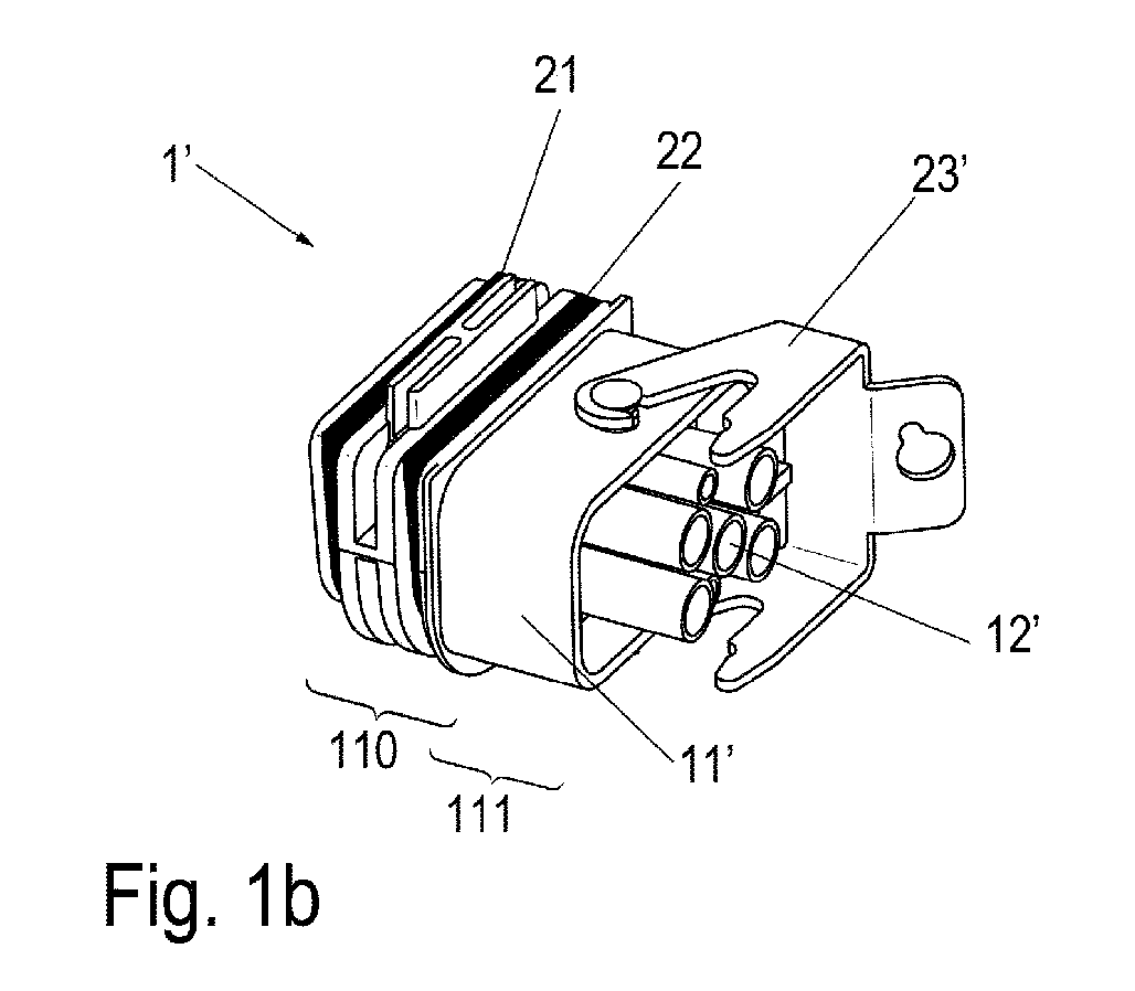
- Fig. 1 shows in (a) an adapter assembly 1, for connecting electrical lines 41 to an electronics housing 5 (s. Fig. 2 ) is provided.
- the adapter assembly 1 has an adapter housing 11, which has an interior 114 and at two opposite end faces 13, 14 each have an opening 131, 141, through which the interior 114 is accessible.
- the adapter assembly 1 has a connector 12 which is arranged in the interior 114 of the adapter housing 11. The connector 12 is also accessible through the openings 131, 141.
- the connector 12 and the adapter or connector housing 11 are in the Fig. 1 (c) separately, so dismantled, shown.
- the connector 12 has a contact side 120 which is accessible with the adapter assembly 1 mounted through the first opening 131, and a connection side 121 which is accessible through the second opening 141.
- the adapter housing 11 has a connection region 111, on which a web is arranged as fastening means 23, as well as a sealing region 110, on which two sealing rings 21, 22 are arranged.
- the sealing rings 21, 22 are provided one behind the other in an extension direction 8 of the adapter housing 11. They can be made of the same or different materials. In addition, they can be inserted in the sealing region 110 or foamed materially.
- the fastening means 23 is provided for fastening a second corresponding adapter arrangement 1 '.
- the second corresponding adapter assembly 1 ' is in the Fig. 1 (b) and (D) shown. It differs from the first adapter assembly 1 by the fastening means 23 'arranged in the connection region 11', which is designed as a bracket 23 'rotatable about an axis of rotation 232.
- the two adapter assemblies 1, 1 ' differ in the design of their connector 12, 12', which is formed in the first adapter assembly 1 as at least one socket and the second corresponding adapter assembly 1 'as at least one plug.
- bracket 23 ' By turning the bracket 23 'from a basic state into a fastening state, the bracket 23' of the second corresponding adapter arrangement 1 'can be locked to the web 23 of the first adapter arrangement 1 when the adapter arrangements 1, 1' are inserted into one another.
- a recess 231 is provided on the bracket 23 ', which engages behind the web 23 in the fastening state.
- the connector 12, 12 ' is detachably arranged in the adapter or connector housing 11, 11'. He is, for example, jammed in the adapter housing, locked or screwed.
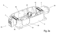
- the Fig. 2 shows an electronic assembly 6.
- the electronics assembly 6 comprises an electronics housing 5 and here two mutually correspondingly designed adapter assemblies 1, 1 ', which are arranged on opposite housing end faces 53, 54 of the electronics housing 5 in receptacles 50 of the electronics housing 5.
- the adapter assemblies 1, 1 ' are interchangeable inserted in the receptacles 50.
- the electronics housing 5 is shown open, so that it is accessible from a lid side.
- the lid or lid member 55 (see FIG. Fig. 3 ) for closing the electronics housing 5 is not shown in this figure.
- the adapter assemblies 1, 1 ' can each be inserted into a receptacle 50 of the electronics housing 5 from the cover side in such a way that the sealing area of the adapter housing is arranged in each case in the receptacle.
- the electronics housing 5 is double-walled in each case in the area of the receptacles 50, wherein each of the arranged in the sealing region 120 sealing rings 21, 22 ensures the seal on one of the two housing walls 500.
- the sealing rings 21, 22 are therefore in each case in sealing contact with a housing wall 500.
- an electronics 40 is arranged in the housing interior 52 of the electronics housing 5.
- the electronics 40 are connected via electrical leads 41 to electrical contacts (not shown) on the contact side 120 of the connectors 12, 12 'accessible from the first opening 131, respectively.
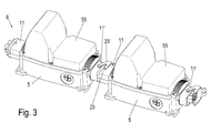
- Fig. 3 are two electronic assemblies 6 according to the Fig. 2 connected in series.
- the connector 12 of the first adapter assembly 1 and the connector 12 'of the second adapter assembly 1 are formed corresponding to each other, so that they are plugged into each other.
- the electronics housing 5 are each closed by a cover member 55. Due to the two sealing rings 21, 22 provided in the sealing region 110 of the adapter arrangement 1, 1 ', the interior space 52 of the electronics housing 5 or an electronics 40 arranged there are in each case well protected against the penetration of dust, moisture and / or EMC.
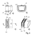
- Fig. 4a-d are the sealing rings 21, 22 of an alternative adapter or connector housing assembly (shown here without inner connector) integrally with each other via a transverse to their planes here web 24, which engages for fixing in a groove connected to each other.
- a two-component production can be used to interpret the sealing rings differently.
- the sealing rings may be inserted or molded onto the housing.
- the sealing rings 21, 22 may be inserted or injected in all embodiments in the sealing region 110 in each case in circumferential outwardly open grooves 115, 116.
Landscapes
- Connector Housings Or Holding Contact Members (AREA)
Abstract


Description
- Die vorliegende Erfindung betrifft eine Adapteranordnung, die zum Anschluss elektrischer Leitungen an ein Elektronikgehäuse vorgesehen ist, sowie eine Elektronikbaugruppe mit dem Elektronikgehäuse und zumindest einer solchen Adapteranordnung.
- Elektronik muss häufig in Staub-, Feuchtigkeits- und/oder EMV belasteten Räumen angeordnet werden. Solche Räume sind beispielsweise Außenanlagen, Fertigungsstraßen und/oder die Umgebung von Starkstromanlagen.
- Aufgabe der Erfindung ist es, eine Elektronikbaugruppe zu schaffen, die ein flexibles hintereinander Schalten mehrerer Elektronikgehäuse ermöglicht und einen sehr guten Staub-, Feuchtigkeits- und/oder EMV- Schutz gewährleistet.
- Die Aufgabe wird gelöst mit einer Adapteranordnung gemäß dem Anspruch 1, einer Adapterbaugruppe gemäß dem Anspruch 8 und einer Elektronikbaugruppe gemäß dem Anspruch 10. Vorteilhafte Ausführungsformen sind den Unteransprüchen zu entnehmen.
- Dafür wird eine Adapteranordnung geschaffen, die zum Anschluss elektrischer Leitungen an ein Elektronikgehäuse vorgesehen ist. Die Adapteranordnung umfasst ein Adaptergehäuse, welches einen Innenraum aufweist, und welches an zwei sich gegenüberliegenden Stirnseiten jeweils eine Öffnung aufweist, sowie einen Steckverbinder, der im Innenraum des Adaptergehäuses angeordnet und jeweils durch die Öffnungen zugänglich ist. Es ist bevorzugt, dass das Adaptergehäuse einen Anschlussbereich mit einem Befestigungsmittel zum Befestigen einer zweiten korrespondierenden Adapteranordnung sowie einen Dichtungsbereich mit zwei Dichtringen zum dichtenden Anordnen im Elektronikgehäuse aufweist. Die Adapteranordnung ist zum Anschließen eines Kabels und/oder eines hintereinander geschalteten Elektronikgehäuses nutzbar.
- Um den erforderlichen Staub-, Feuchtigkeits- und/oder EMV- Schutz zu gewährleiten, sind die Dichtringe bevorzugt in einer Erstreckungsrichtung des Adaptergehäuses hintereinander angeordnet. Vorzugsweise sind einer oder beide Dichtringe im Adaptergehäuse entweder eingelegt, so dass sie flexibel austauschbar ist oder sind, oder eingeschäumt, so dass sie unverlierbar mit dem Adaptergehäuse verbunden ist oder sind. In einer bevorzugten Ausführungsform sind sie aus verschiedenen Materialien gebildet. Dabei ist es bevorzugt, dass eine der Dichtringe als EMV- Schutz ausgebildet ist, wobei die andere der beiden Dichtringe als Staub- und Feuchtigkeitsschutz ausgebildet ist, oder dass beide Dichtringe als Staub- und Feuchtigkeitsschutz ausgebildet sind. Das hintereinander Anordnen der beiden Dichtringe hat nicht nur den Vorteil der flexiblen Anpassbarkeit an die Staub-, Feuchtigkeits- und/oder EMV- Anforderungen, sondern gewährleistet diesbezüglich auch einen besseren Schutz in einer höheren Schutzkategorie.
- Als Befestigungsmittel ist bevorzugt ein Steg oder ein Bügel vorgesehen. Es ist bevorzugt, dass der Bügel um eine Drehachse drehbar ist, so dass er von einem Grundzustand in einen Befestigungszustand drehbar ist. Dadurch ist der Bügel einer ersten Adapteranordnung am Steg einer zweiten Adapteranordnung verriegelbar.
- Der Steckverbinder weist bevorzugt eine Anschlussseite und eine Kontaktseite auf, wobei die Anschlussseite von der zweiten Öffnung des Adaptergehäuses aus zugänglich ist, und wobei die Kontaktseite von der ersten Öffnung des Adaptergehäuses aus zugänglich ist. Dabei ist es bevorzugt, dass die Anschlussseite als Stecker und/oder Buchse ausgebildet ist. An den Steckverbinder ist daher ein korrespondierend ausgebildeter zweiter Steckverbinder anschließbar, insbesondere einsteckbar. An der Kontaktseite sind bevorzugt Anschlussmittel für elektrische Leitungen vorgesehen, beispielsweise Kabelschuhe, so dass die elektrischen Leitungen schnell anschließbar sind.
- Zudem ist der Steckverbinder vorzugsweise lösbar im Adaptergehäuse angeordnet, insbesondere verklemmt, verrastet oder verschraubt. Dadurch ist der Steckverbinder austauschbar oder durch einen anders ausgebildeten Steckverbinder ersetzbar.
- Um die Dichtung auch im Innenraum des Adaptergehäuses zu gewährleisten, weist der Steckverbinder ebenfalls bevorzugt eine erste Innenraumdichtung auf, so dass er dichtend im Adaptergehäuse angeordnet ist. Zusätzlich oder alternativ weist das Adaptergehäuse bevorzugt im Innenraum eine zweite Innenraumdichtung auf. Dadurch können Staub, Feuchtigkeit und/oder EMV auch nicht durch den Innenraum des Adaptergehäuses in ein Elektronikgehäuse eindringen.
- Die Aufgabe wird weiterhin gelöst mit einer Adapterbaugruppe mit zwei solchen Adapteranordnungen. Dabei ist es bevorzugt, dass die Adapteranordnungen zueinander korrespondierend ausgebildet sind. Vorzugsweise sind die Adapteranordnungen aneinander oder ineinander gesteckt. Es ist besonders bevorzugt, dass die erste Adapteranordnung ein erstes Befestigungsmittel und einen ersten Steckverbinder aufweist, und dass die zweite Adapteranordnung ein zweites Befestigungsmittel und einen zweiten Steckverbinder aufweist. Ganz besonders bevorzugt sind das erste Befestigungsmittel korrespondierend zum zweiten Befestigungsmittel und der erste Steckverbinder korrespondierend zum zweiten Steckverbinder ausgebildet. Dadurch sind die Adapteranordnungen hintereinander anordbar und aneinander befestigbar.
- Die erste Adapteranordnung weist bevorzugt als Befestigungsmittel einen Steg auf, wobei die zweite Adapteranordnung ebenfalls bevorzugt als Befestigungsmittel einen Bügel aufweist. Der Bügel ist bevorzugt von einem Grundzustand um eine Drehachse in einen Befestigungszustand drehbar. Im Befestigungszustand hintergreift der Bügel bei ineinander gesteckten Adapteranordnungen bevorzugt den Steg, so dass die beiden Adapteranordnung lösbar aneinander befestigt sind.
- Die Aufgabe wird weiterhin gelöst mit einer Elektronikbaugruppe mit einem Elektronikgehäuse und einer solchen Adapteranordnung oder einer solchen Adapterbaugruppe. Es ist bevorzugt, dass im Elektronikgehäuse eine Elektronik angeordnet ist. Ebenfalls bevorzugt ist das Elektronikgehäuse von einer Deckelseite aus zugänglich. Dabei ist es bevorzugt mit einem Deckel oder einem Deckelbauteil verschließbar.
- Vorzugsweise sind die Dichtringe umfangsgeschlossen ausgebildet.
- Es ist bevorzugt, dass die Adapterbaugruppe bei geöffnetem Elektronikgehäuse in eine Aufnahme des Elektronikgehäuses einlegbar ist, so dass der Dichtungsbereich des Adaptergehäuses in der Aufnahme angeordnet ist. Das Einlegen von der Deckelseite aus ist sehr einfach und schnell möglich.
- Besonders bevorzugt liegen die Dichtringe bei in der Aufnahme eingelegter Adapterbaugruppe am geschlossenen Elektronikgehäuse und am Deckel oder Deckelbauteil dichtend an. Die geschlossene Elektronikbaugruppe ist daher gegen Staub- Feuchtigkeit und/oder EMV sehr gut abgedichtet.
- Bei einer Elektronikbaugruppe mit Adapterbaugruppe ist es bevorzugt, dass beide Adapteranordnungen jeweils in eine Aufnahme eines Elektronikgehäuses eingelegt sind, so dass die Elektronikgehäuse hintereinander geschaltet sind.
- Nachfolgend wird die Erfindung unter Bezug auf die Zeichnungen anhand von Ausführungsbeispielen näher erläutert, wobei weitere Vorteile der Erfindung deutlich werden. Es zeigt:
- Fig. 1
- in (a) und (b) zwei zueinander korrespondierend ausgebildete Adapteranordnungen mit einem Adaptergehäuse und einem im Adaptergehäuse angeordneten Steckverbinder, wobei der Steckverbinder in (c) und (d) außerhalb des Adaptergehäuses gezeigt ist,
- Fig. 2
- in (a) - (c) eine Elektronikbaugruppe mit einem Elektronikgehäuse und zwei Adapteranordnungen, und
- Fig. 3
- zwei geschlossene Elektronikbaugruppe gemäß
Fig. 2 , die hintereinander geschaltet sind; und - Fig. 4
- in (a) bis (d) verschiedene Ansichten und Schnitte einer alternativen Ausgestaltung eines Adapter- bzw. Steckverbindergehäuses.
-
Fig. 1 zeigt in (a) eine Adapteranordnung 1, die zum Anschluss elektrischer Leitungen 41 an ein Elektronikgehäuse 5 (s.Fig. 2 ) vorgesehen ist. Die Adapteranordnung 1 weist ein Adaptergehäuse 11 auf, welches einen Innenraum 114 aufweist und an zwei sich gegenüberliegenden Stirnseiten 13, 14 jeweils eine Öffnung 131, 141, durch die der Innenraum 114 zugänglich ist. Zudem weist die Adapteranordnung 1 einen Steckverbinder 12 auf, der im Innenraum 114 des Adaptergehäuses 11 angeordnet ist. Der Steckverbinder 12 ist ebenfalls durch die Öffnungen 131, 141 zugänglich. - Der Steckverbinder 12 und das Adapter- bzw. Steckverbindergehäuse 11 sind in der
Fig. 1(c) separat, also demontiert, gezeigt. Der Steckverbinder 12 weist eine Kontaktseite 120 auf, die bei montierter Adapteranordnung 1 durch die erste Öffnung 131 zugänglich ist, sowie eine Anschlussseite 121, die durch die zweite Öffnung 141 zugänglich ist. - Das Adaptergehäuse 11 weist einen Anschlussbereich 111 auf, an dem als Befestigungsmittel 23 ein Steg angeordnet ist, sowie einen Dichtungsbereich 110, an dem zwei Dichtringe 21, 22 angeordnet sind. Die Dichtringe 21, 22 sind in einer Erstreckungsrichtung 8 des Adaptergehäuses 11 hintereinander vorgesehen. Sie können aus demselben oder aus verschiedenen Materialien hergestellt sein. Zudem können sie in den Dichtbereich 110 eingelegt oder stoffschlüssig eingeschäumt sein.
- Das Befestigungsmittel 23 ist zum Befestigen einer zweiten korrespondierenden Adapteranordnung 1' vorgesehen. Die zweite korrespondierende Adapteranordnung 1' ist in den
Fig. 1 (b) und(d) gezeigt. Sie unterscheidet sich von der ersten Adapteranordnung 1 durch das im Anschlussbereich 11' angeordnete Befestigungsmittel 23', dass bei ihr als um eine Drehachse 232 drehbarer Bügel 23' ausgebildet ist. Zudem unterscheiden sich die beiden Adapteranordnungen 1, 1' durch die Ausbildung ihres Steckverbinders 12, 12', der bei der ersten Adapteranordnung 1 als wenigstens eine Buchse und bei der zweiten korrespondierenden Adapteranordnung 1' als wenigstens ein Stecker ausgebildet ist. Dadurch sind die Adapteranordnungen 1, 1' ineinander steckbar. - Durch Drehen des Bügels 23' von einem Grundzustand in einen Befestigungszustand ist bei ineinander gesteckten zueinander korrespondierenden Adapteranordungen 1, 1' der Bügel 23' der zweiten korrespondierenden Adapteranordnung 1' mit dem Steg 23 der ersten Adapteranordnung 1 verriegelbar. Dafür ist am Bügel 23' eine Ausnehmung 231 vorgesehen, die im Befestigungszustand den Steg 23 hintergreift.
- Der Steckverbinder 12, 12' ist lösbar im Adapter- bzw. Steckverbindergehäuse 11, 11' angeordnet. Er ist beispielsweise im Adaptergehäuse verklemmt, verrastet oder verschraubt.
- Um eine ausreichende Dichtung des Innenraums 114 des Adaptergehäuses 11, 11' zu gewährleisten, sind zudem im Innenraum 114, d. h. im Adaptergehäuse 11, 11' und/oder am Steckverbinder 12, 12' Innenraum Dichtungen (nicht gezeigt) vorgesehen, die ein Eindringen von Staub, Feuchtigkeit und/oder EMV verhindern.
- Die
Fig. 2 zeigt eine Elektronikbaugruppe 6. Die Elektronikbaugruppe 6 umfasst ein Elektronikgehäuse 5 und hier zwei zueinander korrespondierend ausgebildete Adapteranordnungen 1, 1', die an gegenüberliegenden Gehäusestirnseiten 53, 54 des Elektronikgehäuses 5 in Aufnahmen 50 des Elektronikgehäuses 5 angeordnet sind. Die Adapteranordnungen 1, 1' sind austauschbar in die Aufnahmen 50 eingelegt. Gezeigt ist auch eine Aufnahme 50, in die anstelle einer Adapteranordnung 1, 1' ein Aufnahmeverschluss 51 eingelegt ist. - Das Elektronikgehäuse 5 ist offen dargestellt, so dass es von einer Deckelseite aus zugänglich ist. Der Deckel oder das Deckelbauteil 55 (s.
Fig. 3 ) zum Verschließen des Elektronikgehäuses 5 ist in dieser Fig. nicht dargestellt. - Die Adapterbaugruppen 1, 1' sind bei geöffnetem Elektronikgehäuse 5 jeweils in eine Aufnahme 50 des Elektronikgehäuses 5 von der Deckelseite aus so einlegbar, dass jeweils der Dichtungsbereich des Adaptergehäuses in der Aufnahme angeordnet ist. Um das Eindringen von Staub, Feuchtigkeit und/oder EMV zu verhindern, ist das Elektronikgehäuse 5 jeweils im Bereich der Aufnahmen 50 doppelwandig ausgebildet, wobei jeder der im Dichtbereich 120 angeordneten Dichtringe 21, 22 die Dichtung an einer der beiden Gehäusewände 500 sicherstellt. Bei geschlossenem Elektronikgehäuse 5 liegen die Dichtringe 21, 22 daher jeweils an einer Gehäusewand 500 dichtend an.
- Im Gehäuseinnenraum 52 des Elektronikgehäuses 5 ist eine Elektronik 40 angeordnet. Die Elektronik 40 ist über elektrische Leitungen 41 mit elektrischen Kontakten (nicht gezeigt) an der Kontaktseite 120 der Steckverbinder 12, 12', die jeweils von der ersten Öffnung 131 aus zugänglich sind, verbunden.
- In der
Fig. 3 sind zwei Elektronikbaugruppen 6 gemäß derFig. 2 hintereinander geschaltet. Dabei ist ein Paar der zueinander korrespondierenden Adapteranordnungen 1, 1' zu einer Adapterbaugruppe ineinander gesteckt. Bei dieser Adapterbaugruppe sind daher der Steckverbinder 12 der ersten Adapteranordnung 1 und der Steckverbinder 12' der zweiten Adapteranordnung 1 korrespondierend zueinander ausgebildet, so dass sie ineinander steckbar sind. Zudem sind das erste Befestigungsmittel 23 der ersten Adapteranordnung 1, welches als Steg ausgebildet ist, und das Befestigungsmittel 23' der zweiten Adapteranordnung 1', welches als Bügel ausgebildet ist, zueinander korrespondierend ausgebildet. Dementsprechend ist der Bügel hier im Befestigungszustand gezeigt, in dem er mit dem Steg verriegelt ist. - In dieser Darstellung sind die Elektronikgehäuse 5 jeweils durch ein Deckelbauteil 55 verschlossen. Aufgrund der im Dichtbereich 110 der Adapteranordnung 1, 1' vorgesehenen beiden Dichtringe 21, 22 ist der Innenraum 52 der Elektronikgehäuse 5 beziehungsweise eine dort angeordnete Elektronik 40 jeweils gut gegen das Eindringen von Staub, Feuchtigkeit und/oder EMV geschützt.
- Nach
Fig. 4a-d sind die Dichtringe 21, 22 einer alternativen Adapter- bzw. Steckverbindergehäuseanordnung (hier ohne innere Steckverbinder dargestellt) einstückig miteinander über einen zu ihren Ebenen hier quer ausgerichteten Steg 24, der zur Fixierung in eine Nut eingreift miteinander verbunden. Dabei kann auch eine Zweikomponentenherstellung genutzt werden, um die Dichtringe unterschiedlich auszulegen. Die Dichtringe können eingelegt sein oder an das Gehäuse angespritzt sein. - Die Dichtringe 21, 22 können bei allen Ausführungsbeispielen im Dichtbereich 110 jeweils in umlaufende nach außen offene Nuten 115, 116 eingelegt oder eingespritzt sein.
- Sie können auch zur Verbesserung der Dichtwirkung umlaufend einen (kleinen) radialen Außensteg aufweisen.
-
- 1, 1'
- Adapteranordnung
- 11, 11'
- Adaptergehäuse
- 110
- Dichtungsbereich
- 111
- Anschlussbereich
- 114
- Innenraum
- 12, 12'
- Steckverbinder
- 120
- Kontaktseite
- 121, 121'
- Anschlussseite
- 131
- Erste Öffnung
- 141
- Zweite Öffnung
- 21, 22
- Dichtung
- 23, 23'
- Befestigungsmittel, Steg, Bügel
- 231
- Ausnehmung, Kante
- 232
- Drehachse
- 233
- Drehrichtung
- 40
- Elektronik
- 41
- Elektrische Leitung
- 5
- Elektronikgehäuse
- 50
- Aufnahme
- 500
- Gehäusewand
- 51
- Aufnahmeverschluss
- 52
- Gehäuseinnenraum
- 53, 54
- Gehäusestirnseiten
- 55
- Deckelbauteil
- 6
- Elektronikbaugruppe
- 8
- Erstreckungsrichtung
Claims (12)
- Adapteranordnung (1, 1') zum Anschluss elektrischer Leitungen (41) an ein Elektronikgehäuse (5), mit einem Adaptergehäuse (11, 11'), welches einen Innenraum (114) aufweist, und welches an zwei sich gegenüberliegenden Stirnseiten (13, 14) jeweils eine Öffnung (131, 141) aufweist, sowie mit einem Steckverbinder (12, 12'), der im Innenraum (114) des Adaptergehäuses (11, 11') angeordnet und jeweils durch die Öffnungen (131, 141) zugänglich ist,
dadurch gekennzeichnet, dass
es einen Anschlussbereich (111) mit einem Befestigungsmittel (23, 23') zum Befestigen einer zweiten korrespondierenden Adapteranordnung (1', 1) sowie einen Dichtungsbereich (110) mit zwei Dichtringen (21, 22) zum dichtenden Anordnen im Elektronikgehäuse (5) aufweist. - Adapteranordnung (1, 1') nach Anspruch 1, dadurch gekennzeichnet, dass die Dichtringe (21, 22) einstückig ausgebildet und über wenigstens einen Steg miteinander verbunden sind.
- Adapteranordnung (1, 1') nach Anspruch 1, dadurch gekennzeichnet, dass die Dichtringe (21, 22) getrennt voneinander ausgebildet sind.
- Adapteranordnung (1, 1') nach Anspruch 1, 2 oder 3, dadurch gekennzeichnet, dass die Dichtringe (21, 22) in einer Erstreckungsrichtung (8) des Adaptergehäuses (11) hintereinander angeordnet sind.
- Adapteranordnung (1, 1') nach einem der vorherigen Ansprüche, dadurch gekennzeichnet, dass das Befestigungsmittel (23, 23') ein Steg oder ein Bügel ist.
- Adapteranordnung (1, 1') nach einem der vorherigen Ansprüche, dadurch gekennzeichnet, dass der Steckverbinder (12, 12') eine Anschlussseite (121) und eine Kontaktseite (120) aufweist, wobei die Anschlussseite (121) von der zweiten Öffnung (141) des Adaptergehäuses (11, 11') aus zugänglich ist, und wobei die Kontaktseite (120) von der ersten Öffnung (131) des Adaptergehäuses (11, 11') aus zugänglich ist.
- Adapteranordnung (1, 1') nach einem der vorherigen Ansprüche, dadurch gekennzeichnet, dass die Anschlussseite (121) als Stecker und/oder Buchse ausgebildet ist.
- Adapteranordnung (1, 1') nach einem der vorherigen Ansprüche, dadurch gekennzeichnet, dass der Steckverbinder (12, 12') lösbar im Adaptergehäuse (11, 11') angeordnet ist, insbesondere verklemmt, verrastet oder verschraubt.
- Adapteranordnung (1, 1') nach einem der vorherigen Ansprüche, dadurch gekennzeichnet, dass der Steckverbinder (12, 12') eine Dichtung aufweist, so dass er dichtend im Adaptergehäuse (11, 11') angeordnet ist.
- Adapterbaugruppe mit zwei Adapteranordnungen (1, 1') nach einem der vorherigen Ansprüche, die zueinander korrespondierend ausgebildet und ineinander gesteckt sind, wobei die erste Adapteranordnung (1) ein erstes Befestigungsmittel (23) und einen ersten Steckverbinder (12) aufweist, wobei die zweite Adapteranordnung (1') ein zweites Befestigungsmittel (23') und einen zweiten Steckverbinder (12') aufweist, und wobei das erste Befestigungsmittel (23) korrespondierend zum zweiten Befestigungsmittel (23') und der erste Steckverbinder (12) korrespondierend zum zweiten Steckverbinder (12') ausgebildet sind.
- Adapterbaugruppe nach Anspruch 8, dadurch gekennzeichnet, dass die erste Adapteranordnung (1) als Befestigungsmittel (23) einen Steg und die zweite Adapteranordnung (1') als Befestigungsmittel (23') einen Bügel aufweist, und wobei der Bügel den Steg in einem Befestigungszustand hintergreift.
- Elektronikbaugruppe (6) mit einem Elektronikgehäuse (5) und einer Adapteranordnung (1, 1') nach einem der Ansprüche 1 - 9 oder einer Adapterbaugruppe nach einem der Ansprüche 10 - 11.
Applications Claiming Priority (1)
| Application Number | Priority Date | Filing Date | Title |
|---|---|---|---|
| DE201220104999 DE202012104999U1 (de) | 2012-12-20 | 2012-12-20 | Adapteranordnung |
Publications (2)
| Publication Number | Publication Date |
|---|---|
| EP2747213A1 true EP2747213A1 (de) | 2014-06-25 |
| EP2747213B1 EP2747213B1 (de) | 2021-03-17 |
Family
ID=49679445
Family Applications (1)
| Application Number | Title | Priority Date | Filing Date |
|---|---|---|---|
| EP13195444.8A Active EP2747213B1 (de) | 2012-12-20 | 2013-12-03 | Adapteranordnung |
Country Status (4)
| Country | Link |
|---|---|
| US (1) | US9306313B2 (de) |
| EP (1) | EP2747213B1 (de) |
| CN (1) | CN103887669B (de) |
| DE (1) | DE202012104999U1 (de) |
Families Citing this family (28)
| Publication number | Priority date | Publication date | Assignee | Title |
|---|---|---|---|---|
| US9054449B2 (en) | 2012-01-27 | 2015-06-09 | Chatsworth Products, Inc. | Cable retention system for power distribution unit |
| US20130215581A1 (en) | 2012-01-27 | 2013-08-22 | Chatsworth Products, Inc. | Board-mounted circuit breakers for electronic equipment enclosures |
| DE102012101614A1 (de) * | 2012-02-28 | 2013-08-29 | Phoenix Contact Gmbh & Co. Kg | Vorrichtung zum Verschließen eines Gehäuses eines Steckverbinders |
| CN115313081A (zh) | 2017-04-24 | 2022-11-08 | 康普技术有限责任公司 | 用于单个扭绞导体对的连接器 |
| WO2019011830A1 (en) * | 2017-07-12 | 2019-01-17 | Koninklijke Philips N.V. | MEDICAL IMAGING DEVICE CONNECTOR ASSEMBLY |
| DE102017118212A1 (de) * | 2017-08-10 | 2019-02-14 | Amphenol-Tuchel Electronics Gmbh | Adaptergehäuse |
| CN107611673B (zh) * | 2017-09-12 | 2024-05-24 | 镇江奥博通信设备有限公司 | 一种高性能密封圆形电连接器 |
| CN108281843B (zh) * | 2018-01-26 | 2021-05-21 | 努比亚技术有限公司 | Usb防水接口结构及具有该usb防水接口的移动终端 |
| US10547145B2 (en) * | 2018-02-05 | 2020-01-28 | Chatworth Products, Inc. | Electric receptacle with locking feature |
| CN111937243B (zh) | 2018-02-26 | 2022-07-15 | 康普技术有限责任公司 | 用于单绞合导线对的连接器和触头 |
| CN111869028B (zh) * | 2018-03-22 | 2021-11-09 | 株式会社自动网络技术研究所 | 柔性扁形电缆的连接结构 |
| JP2020161233A (ja) * | 2019-03-25 | 2020-10-01 | 矢崎総業株式会社 | コネクタ |
| DE102019205115B3 (de) * | 2019-04-10 | 2020-08-13 | Icotek Project Gmbh & Co. Kg | Vorrichtung zur Einführung von Leitungen durch eine Öffnung |
| US11721932B2 (en) * | 2019-07-09 | 2023-08-08 | Arris Enterprises Llc | Tool-less service cable connector and corresponding systems and methods |
| JP7202266B2 (ja) * | 2019-07-22 | 2023-01-11 | 株式会社タムラ製作所 | 電子部品ユニット |
| JP7142788B2 (ja) * | 2019-09-04 | 2022-09-27 | 三菱電機株式会社 | 電気機器装置 |
| EP4038430A4 (de) | 2019-09-30 | 2024-02-28 | CommScope Technologies LLC | Kupplungsplatte mit hoher dichte |
| US12316055B2 (en) * | 2019-09-30 | 2025-05-27 | Commscope Technologies Llc | Couplers for single pair connectors |
| TWI748330B (zh) * | 2020-01-17 | 2021-12-01 | 群光電能科技股份有限公司 | 電源裝置之插座組合結構 |
| DE102020106381A1 (de) | 2020-03-09 | 2021-09-09 | Zalux S. A. | Modulares Leuchtenset |
| US11502464B2 (en) * | 2020-04-29 | 2022-11-15 | National Products, Inc. | Multi-port USB cable with cable retention and methods of making and using |
| US12199372B2 (en) | 2021-02-26 | 2025-01-14 | Commscope Technologies Llc | Couplers for single pair connectors |
| US11894729B2 (en) * | 2021-03-13 | 2024-02-06 | Hamilton Sundstrand Corporation | Alternating current connection housing with integrated inserts |
| DE102021113979A1 (de) * | 2021-05-31 | 2022-12-01 | Ipetronik Gmbh & Co. Kg | Messmodul-System |
| CN216624678U (zh) * | 2021-07-16 | 2022-05-27 | 深圳市普玛斯精密组件有限公司 | 一种Type-C母端电连接器 |
| CN116247478B (zh) * | 2023-01-04 | 2025-09-26 | 四川华丰科技股份有限公司 | 多模块组合式转接组件 |
| DE102024122060A1 (de) * | 2024-08-02 | 2026-02-05 | Lufthansa Technik Aktiengesellschaft | Steckergehäuse |
| DE102024131972A1 (de) * | 2024-11-04 | 2026-05-07 | Bayerische Motoren Werke Aktiengesellschaft | Adapteranordnung für elektrische Anschlüsse eines Antriebsenergiespeichers |
Citations (4)
| Publication number | Priority date | Publication date | Assignee | Title |
|---|---|---|---|---|
| DE8812556U1 (de) * | 1988-10-05 | 1988-11-17 | Grote & Hartmann Gmbh & Co Kg, 5600 Wuppertal | Vielpoliger Stecker |
| DE20005860U1 (de) * | 2000-03-28 | 2000-06-15 | HARTING KGaA, 32339 Espelkamp | Adapter für Steckverbinder |
| US20030109166A1 (en) * | 2001-12-06 | 2003-06-12 | Sumitomo Wiring Systems, Ltd. | Connector and method of assembling it |
| US20110189888A1 (en) * | 2010-02-04 | 2011-08-04 | Tyco Electronics Corporation | Header connector assembly |
Family Cites Families (12)
| Publication number | Priority date | Publication date | Assignee | Title |
|---|---|---|---|---|
| JP2590878Y2 (ja) * | 1991-11-12 | 1999-02-24 | 矢崎総業株式会社 | コネクタカバー構造 |
| US5511990A (en) * | 1994-11-14 | 1996-04-30 | General Motors Corporation | Electrical interface connector assembly |
| US6022237A (en) * | 1997-02-26 | 2000-02-08 | John O. Esh | Water-resistant electrical connector |
| JP3278048B2 (ja) * | 1997-10-01 | 2002-04-30 | 住友電装株式会社 | コネクタ |
| US6669506B2 (en) * | 2002-05-06 | 2003-12-30 | New York Air Brake Corporation | Trainline junction box |
| US7355130B2 (en) * | 2004-04-09 | 2008-04-08 | Siemens Information And Communication Networks, Inc. | Cable sealing device |
| EP1691454B1 (de) * | 2005-02-11 | 2011-11-30 | Weidmüller Interface GmbH & Co. KG | Elektrischer Steckverbinder mit Verriegelungsklammern |
| DE102005054601B4 (de) * | 2005-11-14 | 2008-06-05 | Sew-Eurodrive Gmbh & Co. Kg | Elektrogerät |
| DE202006017659U1 (de) * | 2006-03-18 | 2007-08-02 | Weidmüller Interface GmbH & Co. KG | Dichtung für eine Gehäusedurchführung für ein Kabel |
| CN101039019A (zh) * | 2006-03-18 | 2007-09-19 | 威德米勒界面有限公司及两合公司 | 用于电缆的壳体通孔的密封装置 |
| JP4716123B2 (ja) * | 2006-06-16 | 2011-07-06 | 住友電装株式会社 | コネクタ用キャップの保持構造 |
| US7914298B2 (en) * | 2008-10-10 | 2011-03-29 | Tyco Electronics Corporation | Solar box and two position solar connectors |
-
2012
- 2012-12-20 DE DE201220104999 patent/DE202012104999U1/de not_active Expired - Lifetime
-
2013
- 2013-12-03 EP EP13195444.8A patent/EP2747213B1/de active Active
- 2013-12-16 US US14/106,924 patent/US9306313B2/en active Active
- 2013-12-20 CN CN201310712100.2A patent/CN103887669B/zh not_active Expired - Fee Related
Patent Citations (4)
| Publication number | Priority date | Publication date | Assignee | Title |
|---|---|---|---|---|
| DE8812556U1 (de) * | 1988-10-05 | 1988-11-17 | Grote & Hartmann Gmbh & Co Kg, 5600 Wuppertal | Vielpoliger Stecker |
| DE20005860U1 (de) * | 2000-03-28 | 2000-06-15 | HARTING KGaA, 32339 Espelkamp | Adapter für Steckverbinder |
| US20030109166A1 (en) * | 2001-12-06 | 2003-06-12 | Sumitomo Wiring Systems, Ltd. | Connector and method of assembling it |
| US20110189888A1 (en) * | 2010-02-04 | 2011-08-04 | Tyco Electronics Corporation | Header connector assembly |
Also Published As
| Publication number | Publication date |
|---|---|
| CN103887669A (zh) | 2014-06-25 |
| DE202012104999U1 (de) | 2014-04-01 |
| US20140179158A1 (en) | 2014-06-26 |
| CN103887669B (zh) | 2018-11-09 |
| EP2747213B1 (de) | 2021-03-17 |
| US9306313B2 (en) | 2016-04-05 |
Similar Documents
| Publication | Publication Date | Title |
|---|---|---|
| EP2747213B1 (de) | Adapteranordnung | |
| DE112009001624B4 (de) | Kabel-Anbringungsvorrichtung für elektrische Geräte | |
| EP2625751B1 (de) | Elektrischer leitungsverbinder | |
| DE202012101639U1 (de) | Durchführungsgehäuse | |
| DE112019003595T5 (de) | Elektrischer Steckverbinder, der unterschiedliche Dichtungsanordnungen akzeptiert | |
| DE202014101430U1 (de) | Als Kupplung oder Stecker ausgebildete Steckvorrichtung | |
| DE102019207042A1 (de) | Getriebeeinheit sowie Montage einer Getriebeeinheit mit Klemmenblock | |
| AT519366A4 (de) | Anschlussgehäuse und anschlusssystem | |
| DE102019005171A1 (de) | Elektromotor, insbesondere Außenläufermotor | |
| DE102019205115B3 (de) | Vorrichtung zur Einführung von Leitungen durch eine Öffnung | |
| EP4111835A1 (de) | Kabeleinlassvorrichtung für einen schaltschrank sowie anordnung und verfahren zum betrieb derselben | |
| DE102008015128A1 (de) | Dichthülle für ein Unterputz-Installationsgerät | |
| DE102010060754A1 (de) | Gehäuseanordnung zur Aufnahme eines elektronischen Geräts | |
| WO2002021655A1 (de) | Anbaugehäuse | |
| DE19727453A1 (de) | Rundsteckverbinder für ein geschirmtes Kabel | |
| EP2706633B1 (de) | Einsatzstück für Wandöffnungen von Installationsschränken | |
| EP1760838A1 (de) | Elektrisches Steckverbinderteil | |
| DE202017106818U1 (de) | Anordnung für eine Kabeldurchführung | |
| DE102024111614A1 (de) | Adaptermodul für einen modularen Industriesteckverbinder | |
| DE102006062609A1 (de) | Kabeldurch-/-einführungselement zum Dichten, Klemmen, Schirmen und Leiten | |
| DE202011050660U1 (de) | Schutzgehäuse für einen elektrischen Steckverbinder | |
| DE102013201149A1 (de) | Kabeldurchführungseinrichtung | |
| WO2005122340A1 (de) | Verbindungssystem zur geschützten verbindung von leitungen | |
| WO2011032535A1 (de) | Wechselrichter | |
| DE102010055663A1 (de) | Wandeinsatz |
Legal Events
| Date | Code | Title | Description |
|---|---|---|---|
| PUAI | Public reference made under article 153(3) epc to a published international application that has entered the european phase |
Free format text: ORIGINAL CODE: 0009012 |
|
| 17P | Request for examination filed |
Effective date: 20131203 |
|
| AK | Designated contracting states |
Kind code of ref document: A1 Designated state(s): AL AT BE BG CH CY CZ DE DK EE ES FI FR GB GR HR HU IE IS IT LI LT LU LV MC MK MT NL NO PL PT RO RS SE SI SK SM TR |
|
| AX | Request for extension of the european patent |
Extension state: BA ME |
|
| R17P | Request for examination filed (corrected) |
Effective date: 20140812 |
|
| RBV | Designated contracting states (corrected) |
Designated state(s): AL AT BE BG CH CY CZ DE DK EE ES FI FR GB GR HR HU IE IS IT LI LT LU LV MC MK MT NL NO PL PT RO RS SE SI SK SM TR |
|
| STAA | Information on the status of an ep patent application or granted ep patent |
Free format text: STATUS: EXAMINATION IS IN PROGRESS |
|
| 17Q | First examination report despatched |
Effective date: 20190514 |
|
| RAP1 | Party data changed (applicant data changed or rights of an application transferred) |
Owner name: WEIDMUELLER INTERFACE GMBH & CO. KG |
|
| GRAP | Despatch of communication of intention to grant a patent |
Free format text: ORIGINAL CODE: EPIDOSNIGR1 |
|
| STAA | Information on the status of an ep patent application or granted ep patent |
Free format text: STATUS: GRANT OF PATENT IS INTENDED |
|
| INTG | Intention to grant announced |
Effective date: 20201112 |
|
| GRAS | Grant fee paid |
Free format text: ORIGINAL CODE: EPIDOSNIGR3 |
|
| GRAA | (expected) grant |
Free format text: ORIGINAL CODE: 0009210 |
|
| STAA | Information on the status of an ep patent application or granted ep patent |
Free format text: STATUS: THE PATENT HAS BEEN GRANTED |
|
| AK | Designated contracting states |
Kind code of ref document: B1 Designated state(s): AL AT BE BG CH CY CZ DE DK EE ES FI FR GB GR HR HU IE IS IT LI LT LU LV MC MK MT NL NO PL PT RO RS SE SI SK SM TR |
|
| REG | Reference to a national code |
Ref country code: GB Ref legal event code: FG4D Free format text: NOT ENGLISH |
|
| REG | Reference to a national code |
Ref country code: CH Ref legal event code: EP |
|
| REG | Reference to a national code |
Ref country code: DE Ref legal event code: R096 Ref document number: 502013015564 Country of ref document: DE |
|
| REG | Reference to a national code |
Ref country code: IE Ref legal event code: FG4D Free format text: LANGUAGE OF EP DOCUMENT: GERMAN |
|
| REG | Reference to a national code |
Ref country code: AT Ref legal event code: REF Ref document number: 1373117 Country of ref document: AT Kind code of ref document: T Effective date: 20210415 |
|
| REG | Reference to a national code |
Ref country code: LT Ref legal event code: MG9D |
|
| PG25 | Lapsed in a contracting state [announced via postgrant information from national office to epo] |
Ref country code: FI Free format text: LAPSE BECAUSE OF FAILURE TO SUBMIT A TRANSLATION OF THE DESCRIPTION OR TO PAY THE FEE WITHIN THE PRESCRIBED TIME-LIMIT Effective date: 20210317 Ref country code: HR Free format text: LAPSE BECAUSE OF FAILURE TO SUBMIT A TRANSLATION OF THE DESCRIPTION OR TO PAY THE FEE WITHIN THE PRESCRIBED TIME-LIMIT Effective date: 20210317 Ref country code: GR Free format text: LAPSE BECAUSE OF FAILURE TO SUBMIT A TRANSLATION OF THE DESCRIPTION OR TO PAY THE FEE WITHIN THE PRESCRIBED TIME-LIMIT Effective date: 20210618 Ref country code: BG Free format text: LAPSE BECAUSE OF FAILURE TO SUBMIT A TRANSLATION OF THE DESCRIPTION OR TO PAY THE FEE WITHIN THE PRESCRIBED TIME-LIMIT Effective date: 20210617 Ref country code: NO Free format text: LAPSE BECAUSE OF FAILURE TO SUBMIT A TRANSLATION OF THE DESCRIPTION OR TO PAY THE FEE WITHIN THE PRESCRIBED TIME-LIMIT Effective date: 20210617 |
|
| REG | Reference to a national code |
Ref country code: NL Ref legal event code: MP Effective date: 20210317 |
|
| PG25 | Lapsed in a contracting state [announced via postgrant information from national office to epo] |
Ref country code: SE Free format text: LAPSE BECAUSE OF FAILURE TO SUBMIT A TRANSLATION OF THE DESCRIPTION OR TO PAY THE FEE WITHIN THE PRESCRIBED TIME-LIMIT Effective date: 20210317 Ref country code: LV Free format text: LAPSE BECAUSE OF FAILURE TO SUBMIT A TRANSLATION OF THE DESCRIPTION OR TO PAY THE FEE WITHIN THE PRESCRIBED TIME-LIMIT Effective date: 20210317 Ref country code: RS Free format text: LAPSE BECAUSE OF FAILURE TO SUBMIT A TRANSLATION OF THE DESCRIPTION OR TO PAY THE FEE WITHIN THE PRESCRIBED TIME-LIMIT Effective date: 20210317 |
|
| PG25 | Lapsed in a contracting state [announced via postgrant information from national office to epo] |
Ref country code: NL Free format text: LAPSE BECAUSE OF FAILURE TO SUBMIT A TRANSLATION OF THE DESCRIPTION OR TO PAY THE FEE WITHIN THE PRESCRIBED TIME-LIMIT Effective date: 20210317 |
|
| PG25 | Lapsed in a contracting state [announced via postgrant information from national office to epo] |
Ref country code: EE Free format text: LAPSE BECAUSE OF FAILURE TO SUBMIT A TRANSLATION OF THE DESCRIPTION OR TO PAY THE FEE WITHIN THE PRESCRIBED TIME-LIMIT Effective date: 20210317 Ref country code: CZ Free format text: LAPSE BECAUSE OF FAILURE TO SUBMIT A TRANSLATION OF THE DESCRIPTION OR TO PAY THE FEE WITHIN THE PRESCRIBED TIME-LIMIT Effective date: 20210317 Ref country code: LT Free format text: LAPSE BECAUSE OF FAILURE TO SUBMIT A TRANSLATION OF THE DESCRIPTION OR TO PAY THE FEE WITHIN THE PRESCRIBED TIME-LIMIT Effective date: 20210317 Ref country code: SM Free format text: LAPSE BECAUSE OF FAILURE TO SUBMIT A TRANSLATION OF THE DESCRIPTION OR TO PAY THE FEE WITHIN THE PRESCRIBED TIME-LIMIT Effective date: 20210317 |
|
| PG25 | Lapsed in a contracting state [announced via postgrant information from national office to epo] |
Ref country code: IS Free format text: LAPSE BECAUSE OF FAILURE TO SUBMIT A TRANSLATION OF THE DESCRIPTION OR TO PAY THE FEE WITHIN THE PRESCRIBED TIME-LIMIT Effective date: 20210717 Ref country code: RO Free format text: LAPSE BECAUSE OF FAILURE TO SUBMIT A TRANSLATION OF THE DESCRIPTION OR TO PAY THE FEE WITHIN THE PRESCRIBED TIME-LIMIT Effective date: 20210317 Ref country code: PL Free format text: LAPSE BECAUSE OF FAILURE TO SUBMIT A TRANSLATION OF THE DESCRIPTION OR TO PAY THE FEE WITHIN THE PRESCRIBED TIME-LIMIT Effective date: 20210317 Ref country code: PT Free format text: LAPSE BECAUSE OF FAILURE TO SUBMIT A TRANSLATION OF THE DESCRIPTION OR TO PAY THE FEE WITHIN THE PRESCRIBED TIME-LIMIT Effective date: 20210719 Ref country code: ES Free format text: LAPSE BECAUSE OF FAILURE TO SUBMIT A TRANSLATION OF THE DESCRIPTION OR TO PAY THE FEE WITHIN THE PRESCRIBED TIME-LIMIT Effective date: 20210317 Ref country code: SK Free format text: LAPSE BECAUSE OF FAILURE TO SUBMIT A TRANSLATION OF THE DESCRIPTION OR TO PAY THE FEE WITHIN THE PRESCRIBED TIME-LIMIT Effective date: 20210317 |
|
| REG | Reference to a national code |
Ref country code: DE Ref legal event code: R097 Ref document number: 502013015564 Country of ref document: DE |
|
| PLBE | No opposition filed within time limit |
Free format text: ORIGINAL CODE: 0009261 |
|
| STAA | Information on the status of an ep patent application or granted ep patent |
Free format text: STATUS: NO OPPOSITION FILED WITHIN TIME LIMIT |
|
| PG25 | Lapsed in a contracting state [announced via postgrant information from national office to epo] |
Ref country code: DK Free format text: LAPSE BECAUSE OF FAILURE TO SUBMIT A TRANSLATION OF THE DESCRIPTION OR TO PAY THE FEE WITHIN THE PRESCRIBED TIME-LIMIT Effective date: 20210317 Ref country code: AL Free format text: LAPSE BECAUSE OF FAILURE TO SUBMIT A TRANSLATION OF THE DESCRIPTION OR TO PAY THE FEE WITHIN THE PRESCRIBED TIME-LIMIT Effective date: 20210317 |
|
| 26N | No opposition filed |
Effective date: 20211220 |
|
| PG25 | Lapsed in a contracting state [announced via postgrant information from national office to epo] |
Ref country code: SI Free format text: LAPSE BECAUSE OF FAILURE TO SUBMIT A TRANSLATION OF THE DESCRIPTION OR TO PAY THE FEE WITHIN THE PRESCRIBED TIME-LIMIT Effective date: 20210317 |
|
| PG25 | Lapsed in a contracting state [announced via postgrant information from national office to epo] |
Ref country code: IT Free format text: LAPSE BECAUSE OF FAILURE TO SUBMIT A TRANSLATION OF THE DESCRIPTION OR TO PAY THE FEE WITHIN THE PRESCRIBED TIME-LIMIT Effective date: 20210317 |
|
| PG25 | Lapsed in a contracting state [announced via postgrant information from national office to epo] |
Ref country code: IS Free format text: LAPSE BECAUSE OF FAILURE TO SUBMIT A TRANSLATION OF THE DESCRIPTION OR TO PAY THE FEE WITHIN THE PRESCRIBED TIME-LIMIT Effective date: 20210717 |
|
| PG25 | Lapsed in a contracting state [announced via postgrant information from national office to epo] |
Ref country code: MC Free format text: LAPSE BECAUSE OF FAILURE TO SUBMIT A TRANSLATION OF THE DESCRIPTION OR TO PAY THE FEE WITHIN THE PRESCRIBED TIME-LIMIT Effective date: 20210317 |
|
| REG | Reference to a national code |
Ref country code: CH Ref legal event code: PL |
|
| GBPC | Gb: european patent ceased through non-payment of renewal fee |
Effective date: 20211203 |
|
| REG | Reference to a national code |
Ref country code: BE Ref legal event code: MM Effective date: 20211231 |
|
| PG25 | Lapsed in a contracting state [announced via postgrant information from national office to epo] |
Ref country code: LU Free format text: LAPSE BECAUSE OF NON-PAYMENT OF DUE FEES Effective date: 20211203 Ref country code: IE Free format text: LAPSE BECAUSE OF NON-PAYMENT OF DUE FEES Effective date: 20211203 Ref country code: GB Free format text: LAPSE BECAUSE OF NON-PAYMENT OF DUE FEES Effective date: 20211203 |
|
| PG25 | Lapsed in a contracting state [announced via postgrant information from national office to epo] |
Ref country code: FR Free format text: LAPSE BECAUSE OF NON-PAYMENT OF DUE FEES Effective date: 20211231 Ref country code: BE Free format text: LAPSE BECAUSE OF NON-PAYMENT OF DUE FEES Effective date: 20211231 |
|
| PG25 | Lapsed in a contracting state [announced via postgrant information from national office to epo] |
Ref country code: LI Free format text: LAPSE BECAUSE OF NON-PAYMENT OF DUE FEES Effective date: 20211231 Ref country code: CH Free format text: LAPSE BECAUSE OF NON-PAYMENT OF DUE FEES Effective date: 20211231 |
|
| REG | Reference to a national code |
Ref country code: AT Ref legal event code: MM01 Ref document number: 1373117 Country of ref document: AT Kind code of ref document: T Effective date: 20211203 |
|
| PG25 | Lapsed in a contracting state [announced via postgrant information from national office to epo] |
Ref country code: AT Free format text: LAPSE BECAUSE OF NON-PAYMENT OF DUE FEES Effective date: 20211203 |
|
| PG25 | Lapsed in a contracting state [announced via postgrant information from national office to epo] |
Ref country code: HU Free format text: LAPSE BECAUSE OF FAILURE TO SUBMIT A TRANSLATION OF THE DESCRIPTION OR TO PAY THE FEE WITHIN THE PRESCRIBED TIME-LIMIT; INVALID AB INITIO Effective date: 20131203 |
|
| P01 | Opt-out of the competence of the unified patent court (upc) registered |
Effective date: 20230521 |
|
| PG25 | Lapsed in a contracting state [announced via postgrant information from national office to epo] |
Ref country code: CY Free format text: LAPSE BECAUSE OF FAILURE TO SUBMIT A TRANSLATION OF THE DESCRIPTION OR TO PAY THE FEE WITHIN THE PRESCRIBED TIME-LIMIT Effective date: 20210317 |
|
| PG25 | Lapsed in a contracting state [announced via postgrant information from national office to epo] |
Ref country code: MK Free format text: LAPSE BECAUSE OF FAILURE TO SUBMIT A TRANSLATION OF THE DESCRIPTION OR TO PAY THE FEE WITHIN THE PRESCRIBED TIME-LIMIT Effective date: 20210317 |
|
| PG25 | Lapsed in a contracting state [announced via postgrant information from national office to epo] |
Ref country code: TR Free format text: LAPSE BECAUSE OF FAILURE TO SUBMIT A TRANSLATION OF THE DESCRIPTION OR TO PAY THE FEE WITHIN THE PRESCRIBED TIME-LIMIT Effective date: 20210317 |
|
| PG25 | Lapsed in a contracting state [announced via postgrant information from national office to epo] |
Ref country code: MT Free format text: LAPSE BECAUSE OF FAILURE TO SUBMIT A TRANSLATION OF THE DESCRIPTION OR TO PAY THE FEE WITHIN THE PRESCRIBED TIME-LIMIT Effective date: 20210317 |
|
| PGFP | Annual fee paid to national office [announced via postgrant information from national office to epo] |
Ref country code: DE Payment date: 20251211 Year of fee payment: 13 |