EP2746945A2 - Verfahren und Vorrichtung zum Steuern von DSP-Kanälen - Google Patents
Verfahren und Vorrichtung zum Steuern von DSP-Kanälen Download PDFInfo
- Publication number
- EP2746945A2 EP2746945A2 EP13005731.8A EP13005731A EP2746945A2 EP 2746945 A2 EP2746945 A2 EP 2746945A2 EP 13005731 A EP13005731 A EP 13005731A EP 2746945 A2 EP2746945 A2 EP 2746945A2
- Authority
- EP
- European Patent Office
- Prior art keywords
- channel
- digital signal
- signal processor
- dsp
- request
- Prior art date
- Legal status (The legal status is an assumption and is not a legal conclusion. Google has not performed a legal analysis and makes no representation as to the accuracy of the status listed.)
- Granted
Links
Images



Classifications
-
- H—ELECTRICITY
- H04—ELECTRIC COMMUNICATION TECHNIQUE
- H04L—TRANSMISSION OF DIGITAL INFORMATION, e.g. TELEGRAPHIC COMMUNICATION
- H04L47/00—Traffic control in data switching networks
- H04L47/10—Flow control; Congestion control
- H04L47/12—Avoiding congestion; Recovering from congestion
- H04L47/125—Avoiding congestion; Recovering from congestion by balancing the load, e.g. traffic engineering
-
- G—PHYSICS
- G06—COMPUTING OR CALCULATING; COUNTING
- G06F—ELECTRIC DIGITAL DATA PROCESSING
- G06F9/00—Arrangements for program control, e.g. control units
- G06F9/06—Arrangements for program control, e.g. control units using stored programs, i.e. using an internal store of processing equipment to receive or retain programs
- G06F9/46—Multiprogramming arrangements
- G06F9/50—Allocation of resources, e.g. of the central processing unit [CPU]
- G06F9/5005—Allocation of resources, e.g. of the central processing unit [CPU] to service a request
- G06F9/5027—Allocation of resources, e.g. of the central processing unit [CPU] to service a request the resource being a machine, e.g. CPUs, Servers, Terminals
- G06F9/505—Allocation of resources, e.g. of the central processing unit [CPU] to service a request the resource being a machine, e.g. CPUs, Servers, Terminals considering the load
-
- H—ELECTRICITY
- H04—ELECTRIC COMMUNICATION TECHNIQUE
- H04L—TRANSMISSION OF DIGITAL INFORMATION, e.g. TELEGRAPHIC COMMUNICATION
- H04L25/00—Baseband systems
- H04L25/02—Details ; arrangements for supplying electrical power along data transmission lines
- H04L25/0202—Channel estimation
- H04L25/024—Channel estimation channel estimation algorithms
- H04L25/0242—Channel estimation channel estimation algorithms using matrix methods
-
- H—ELECTRICITY
- H04—ELECTRIC COMMUNICATION TECHNIQUE
- H04L—TRANSMISSION OF DIGITAL INFORMATION, e.g. TELEGRAPHIC COMMUNICATION
- H04L43/00—Arrangements for monitoring or testing data switching networks
- H04L43/08—Monitoring or testing based on specific metrics, e.g. QoS, energy consumption or environmental parameters
- H04L43/0876—Network utilisation, e.g. volume of load or congestion level
- H04L43/0882—Utilisation of link capacity
-
- H—ELECTRICITY
- H04—ELECTRIC COMMUNICATION TECHNIQUE
- H04L—TRANSMISSION OF DIGITAL INFORMATION, e.g. TELEGRAPHIC COMMUNICATION
- H04L47/00—Traffic control in data switching networks
- H04L47/10—Flow control; Congestion control
- H04L47/12—Avoiding congestion; Recovering from congestion
- H04L47/122—Avoiding congestion; Recovering from congestion by diverting traffic away from congested entities
Definitions
- the invention relates to a method and apparatus for controlling DSP channels, more specifically, for managing channels on digital signal processors.
- DSPs digital signal processors
- the DSPs are also used for the digital coding and decoding of signals, in particular speech signals.
- codecs For the coding and decoding of the transmitted signals, recourse is made to predefined methods, so-called codecs. Examples of audio codecs are known and standardized under the designations G.711, G.722, G.723, G.728, G.729, T.38, etc., which include, among other things, the required computing power (so-called. Performance requirements) differ from each other. When a performance requirement of a codec exceeds the available performance of a DSP, the DSP becomes overloaded.
- connection is reassigned to a channel of a DSP by a channel management process running on a host processor or by a codec change requested on a channel by a connection partner.
- the voice quality of a transmission channel may suffer or the channel or the connection may be interrupted.
- a method of channel management on digital signal processors is proposed wherein the channel management occurs at each instant on the basis of a current load of each DSP taking into account an actual power requirement of each channel and a maximum total power of each DSP.
- DSP digital signal processors
- a dynamic channel management becomes possible such that a determination of the actual momentary utilization is made every time a channel management operation concerning a power request is performed.
- Channel management is understood to mean, in particular, the allocation of resources by DSPs, such as, but not limited to, reassigning a channel when reconnecting, or releasing performance when the performance requirements of an existing communication connection change.
- a security surcharge for the actual Use of current occupied or occupied channels when determining the utilization of a considered DSP, a security surcharge for the actual Use of current occupied or occupied channels.
- a safety margin allows for dynamic variations in performance and / or requirements, such as changes in the codec in an ongoing communication.
- an occupied channel is to be understood as meaning a channel over which communications are already being handled, and a subset of a channel to be occupied is to be understood as an in-progress request to reassign a channel for a communication.
- the safety margin is preferably calculated from a difference between a maximum power requirement and a minimum power requirement of all codecs supported by the DSP under consideration and a boost factor. This calculation makes it possible to optimize the safety margin individually for a possible change in the performance requirement by codec changes within the scope of the codecs actually supported by the DSP. In doing so, the difference indicates the largest possible power demand jump that would occur when switching from the lowest power codec to the highest power codec, while the increase factor is to be understood as a factor that indicates how many such maximum power power jumps simultaneously should be manageable.
- the boost factor, the power demand values of the supported codecs, and the maximum overall power are determined in advance for each DSP.
- the power requirements of the supported codecs and the maximum overall performance can be understood as configuration data of each DSP.
- the determination of this configuration data can be done, for example, from data sheets and / or real measurements.
- the determination of the increase factor can, for example, be a determination by configuration on the basis of empirical values and / or boundary conditions of the deployment environment.
- the setup of the Konfiguratinoschal example but not only, via Systemkonfiguratino, eg Web BAsed Management done.
- the channel management is performed by a central instance and a plurality of decentralized instances, each decentralized instance being assigned to a DSP individually.
- an entity can be understood as a subprocess or a subroutine of an overall process, that is to say a software unit, and / or a hardware unit.
- the division into a central instance and several decentralized instances makes it possible to carry out process steps involving several DSPs in a higher-level process and to carry out process steps which concern only a single DSP in an individualized process, wherein a parallel processing of a plurality of individualized processes, in addition to the constantly running in the background superordinate process, is possible.
- the decentralized entities are set up and designed to forward performance data of their assigned DSP to the central entity.
- the configuration data and the safety margin of an individual DSP can be initialized and the current utilization dynamically determined in the decentralized instance and made available to the central entity virtually in real time, in order to be used there for higher-level load balancing processes.
- the decentralized instances are requestable by the central entity.
- processes of the decentralized instances can be requested by the central instance if required.
- Inquiries concerning, for example, the rebuilding of a communication channel can be preprocessed from the central entity, while the corresponding decentralized entity is called up for concrete channel assignment and recalculation of the utilization.
- a channel request is understood to be a request directed to the central entity to establish a communication channel.
- a request for a new channel request is understood to mean a request directed by the central authority to a decentralized instance to set up a new communication channel.
- the method is particularly suitable for managing a request to occupy a new channel.
- the current utilization of the DSPs can be taken into account dynamically for the management of channels.
- variations in performance and / or requirements, such as changes in the codec in an ongoing communication may be dynamically accounted for.
- the performance data of the nominated DSP can be made available to the central entity for further administrative steps in the event of a channel relocation virtually in real time.
- the central entity can always access updated performance or utilization data. This way, system power reserves can be better utilized and the efficiency and performance of the system can be increased.
- the invention is also directed, in a further aspect, to a device for channel management on digital signal processors, which is set up and adapted to carry out the method described above.
- the device can be set up and designed to implement a central instance and a plurality of decentralized entities. It is understood that the realization of the instances by separate hardware components and / or by computer program constructs on one and the same or distributed hardware components can be realized.
- a system 100 includes four digital signal processors (abbreviated to DSP hereinafter) 111 (DSP1), 112 (DSP2), 113 (DSP3), 114 (DSP4), a host processor 120, and a memory 150 on.
- DSP1 digital signal processors
- DSP2 digital signal processors
- DSP3 digital signal processors
- DSP4 digital signal processors
- the system is a gateway device in a telecommunication device and the digital signal processors 111-114, the host processor 120 and the memory 150 are housed on the same board.
- the components may be housed on different boards.
- host processor 120, memory 150, and digital signal processors 111-114 may be implemented in distributed devices.
- the memory 150 may be distributed on a plurality of boards.
- a host processor 120 To perform channel management of voice communication channels (hereinafter referred to as channels) onto the DSP 111-114, a host processor 120 is provided.
- the host processor 120 includes a central load balancing process (hereinafter abbreviated to DLB or DSP Load Balancing Process) 130 and, for each DSP present in the system, a dedicated DSP load control process (hereafter abbreviated to DLC or DLC).
- DLB central load balancing process
- DLC dedicated DSP load control process
- DLC 141 (DLC 1) is associated with digital signal processor 111 (DSP 1)
- DLC 142 (DLC 2) is associated with digital signal processor 112 (DSP 2)
- DLC 143 (DLC 3) is the digital signal processor 113 (DSP 3)
- DLC 144 (DLC 4) is associated with the digital signal processor 114 (DSP 4).
- the memory 150 has a DLB memory area 160 and for each DLC (DLC1-DCL4) a dedicated DLC memory area 171-174.
- a performance table PT is created, which describes a utilization state of the system from the perspective of the DLB process 130.
- a basic data BD area and a channel occupancy table KT are created.
- base data BD and a channel assignment table KT for the DSP 111 are stored in the dedicated memory area 171
- base data BD and a channel assignment table KT for the DSP 112 are stored in the dedicated memory area 172
- basic data BD and a channel assignment table KT for the DSP 113 are stored in the dedicated memory area 173
- base data BD and a channel assignment table KT for the DSP 114 are stored in the dedicated memory area 174.
- the basic data BD describes a basic configuration of the DSP controlled by the respective DLC
- the channel occupancy tables KT describe a channel occupation state of the respective DSP.
- Fig. 2 is a sign in process for a digital signal processor, such as one of the digital signal processors 111-114 ( Fig. 1 ) as implemented by a DSP Load Control Process (DLC), particularly each of the DLCs 141-144 in FIG Fig. 1 for registering a DSP to the central load balancing process DLB 130 of Fig. 1 shown schematically according to the preferred embodiment of the present invention.
- DLC DSP Load Control Process
- the login process 200 includes a determination step 210, a calculation step 220, and a notification step 230.
- the values for max GP and the supported codecs are determined from data sheets and / or real measurements and are as basic data BD in the respective dedicated memory area 171, ..., 174 filed.
- the hysteresis requirement HB is determined, for example, by configuration.
- a maximum and a minimum performance requirement PpC max , PpC min and a maximum hysteresis H max of the DSP 111 (DSP1) are calculated, wherein the values determined in step 210 are used for the calculation.
- the maximum hysteresis H max is a safety margin and the hysteresis requirement HB is an increase factor
- the performance requirement PpC is a power requirement of a codec
- the total performance value number GP max is a maximum overall performance of a DSP.
- the login process 200 is performed in each of the DLCs 141-144 for the respective associated DSP 111-114 in the present embodiment.
- the reported values are displayed in the performance table 160 (FIG. Fig. 1 ) PT stored in the DLB memory area 160 of the memory 150.
- the performance table After logging in all DSP 111-114, for example, after the system has been booted up, the performance table has, for example, the following values: Table 2: Performance table after startup DSP GP max GP's GP inProc PpC max H max 1 100 0 0 20 24 2 200 0 0 25 30 3 200 0 0 25 30 4 120 0 0 10 16
- the maximum performance requirement PpC max is also preferably stored in the base data BD of the respective dedicated memory area 171,..., 174 of the memory 150 for further use and accessed there by various processes of the respective DLC 141,.
- the processes of the DLC 141-144 access the performance table PT in the DLB storage area 160; this would save storage space but may require additional overhead in data management, allocation and processing.
- DSP1 (111 in Fig. 1 ) Channels with a total performance (GP) 90 from, wrapped DSP2 (112 in Fig. 1 ) Channels with a total performance of 120, DSP3 (113 in Fig. 1 ) Channels with a total performance of 80, and wraps DSP4 (114 in Fig. 1 ) Channels with a total performance of 70.
- the load control process DLC of the DSP 3 is currently processing a channel redistribution request (GP inProc ) and the DLC of the DSP 4 is currently processing two such requests.
- Fig. 3 illustrates in the form of a flow chart a process 300 performed in the DLB for processing a new channel request.
- Such a channel request is first routed to the DLB process.
- the process 300 is a subroutine that is called in the current DLB process when a new channel request is made to the system.
- a free DSP is to be understood as a DSP whose overall performance reported and stored in the performance table is less than the maximum performance of the respective DSP, taking into account the maximum hysteresis and the currently processed and newly added channel requirements and the respective performance requirements.
- a DSP is thus considered free in this process step if the condition: GP is + H Max + GP INPROC + 1 * PPC Max ⁇ GP Max is satisfied.
- the calculation in step 310 can be illustrated in the following table: Table 4: Calculation of free DSPs DSP GP is + H max + ( GP inProc + 1) * PpC max Erg. GP max Erg. ⁇ GP max 1 90 + 24 + (0 + 1) * 20 134 100 false 2 120 + 30 + (0 + 1) * 25 175 200 true 3 80 + 30 + (1 + 1) * 25 160 200 true 4 70 + 16 + (2 + 1) * 10 116 120 true
- step 320 it is judged whether there is at least one free DSP among the existing DSPs. This is the case if at least one of the calculation results is true. If the judgment in step 320 is negative (i.e., no DSP is idle), process 300 branches to step 325, otherwise to step 330.
- step 325 following a negative judgment in step 320, the channel request is rejected, and then the process ends.
- An ending of the process is generally to be understood as meaning a return to a calling process, in particular to the DLB process which is the parent of the process 300.
- the load reserve calculated in step 330 is used.
- the load reserve calculated at step 330 (it is a relative load reserve related to the maximum load of the codecs supported by the respective DSP) is a measure of the current load (or load) of the respective DSP.
- DSP3 is determined with a load reserve of 2.8 as the DSP with the lowest load.
- the performance table is updated by increasing the value "GP InProc " by "1" for the lowest current load DSP determined in step 340. That is, the GP InProc value is incremented by "1" for the DSP3.
- the performance table looks like this: Table 6: Performance table after update for channel request DSP GP max GP is GP inProc PpC max H max 1 100 90 0 20 24 2 200 120 0 25 30 3 200 80 2 25 30 4 120 70 2 10 16
- a channel re-allocation request is made to the DSP with the lowest load or the largest relative determined in step 340 Load reserve transmitted.
- this process ends or returns to the calling process.
- Fig. 4 1 illustrates in the form of a flow chart a process 400 performed in the DLC process for processing a request for a new channel (establishment of a communication channel).
- the process 400 is a subroutine that is called in the current DLC process of a DLB when a channel resubmation request is forwarded to that DLB by the DLB process or its channel request process 300, respectively (see step 360 in FIG Fig. 3 ).
- the process 400 can be called in parallel, that is to say for several queries, in parallel.
- DLB 130 in Fig. 1
- the process 300 of DSP3 determines the DSP3 as the DSP3 with the least load and, therefore, forwards the channel resubmation request to the DSP3.
- the current channel occupancy is expressed by the following table: Table 7: Channel assignment when the process 400 is called Channel k 1 2 3 ... codec G.723 (-) G.711 ... PPC 14 0 8th ...
- the channel allocation table KT may have both "Codec” and "PpC” lines of Table 7, but only one of the named lines, because both the specification of the codec itself and the indication of the associated performance is PpC clearly defines the assignment of a channel. It can therefore be stored in the channel assignment table KT for each channel, only one identifier for the codec, the link between the codecs and the associated performance value in the base data BD of the respective memory area 171, ..., 174 ( Fig. 1 ) given is. Alternatively, when a channel is occupied, the performance value of the agreed codec can be retrieved from the basic data BD and stored in the channel assignment table KT. Table 7, as well as tables for channel assignment given below, therefore primarily serve the clarity and the traceability of the numerical example.
- the performance PpC of each channel is an actual power requirement of the channel in the sense of the invention.
- step 420 it is judged whether the DSP is actually free. The judgment in step 420 is positive if the relationship GP is + PPC Max + H Max ⁇ GP Max is satisfied.
- step 420 If the judgment in step 420 is negative, that is, if it is judged that the DSP is not free, the process branches to step 425, otherwise to step 430.
- step 425 following a negative judgment in step 420, the channel request is rejected and the process 400 ends.
- step 420 (including the calculation in step 410) is performed at the beginning of the process 400, although in the DLB channel request process 300 (FIG. Fig. 3 ) the DSP was determined to be free.
- the DLB channel request process 300 (FIG. Fig. 3 ) accesses the data already reported in the performance table.
- a codec switching took place in one or more channels of the DSP, which has not yet been reported to the DLB process. Therefore, the actual performance value GP may have changed (increased), which means that the DSP is no longer free. Therefore, at this level, it must also be possible to reject a Kanane submission request.
- a free channel is determined. This can be any free channel; It is only important that the channel in the channel assignment table is clearly identifiable.
- the free channel determined in step 430 will be referred to hereinafter as the nominated channel.
- channel # 2 is determined to be free and nominated.
- the channel nominated in step 430 is initially pre-assigned the maximum performance value PpC max .
- PpC max for the requested DSP3 results from the performance table PT (Table 3) or from the basic data BP for the DSP 3.
- Table 8 Channel assignment according to default Channel k 1 2 3 ... codec G.723 PpC max G.711 ... PPC 14 20 8th ...
- step 450 it is checked whether the codec for the channel request is already determined. This is done by receiving partner data, ie a remote station of the desired communication channel. If the test in step 450 is negative, i.e., a channel request codec has not yet been received, process 400 branches to step 460, otherwise to step 470.
- step 460 following a negative test in step 450, it is checked whether a maximum waiting time Tmax has elapsed.
- T max The definition of a maximum waiting time T max is useful in order to prevent an endless loop, which could lead to a permanent pre-assignment of channels for channel requirements which have become obsolete.
- step 460 If the test in step 460 is negative, ie, the maximum waiting time T max has not yet elapsed, the process 400 returns to the test in step 450 to check again whether the codec is now determined.
- step 460 If the test in step 460 is positive, ie, the maximum waiting time T max has elapsed, the process 400 branches to step 465 to clear the pre-assignment of the nominated channel after the maximum waiting time T max has expired.
- step 465 which is reached when the maximum waiting time T max has elapsed, the entry of the codec for the nominated channel or the performance value PpC for the nominated channel is deleted in the channel assignment table KT Channel set to the value "0". Thereafter, the process 400 jumps to step 425 to reject the channel relocation request, and the process 400 ends.
- step 470 following a positive check in step 450, the channel assignment for the nominated channel is corrected. That is, in the channel assignment table KT for the nominated channel, the identifier for the specific codec and / or the performance value PpC for the specific codec deposited. For the present numerical example, assume that the particular codec should be G.723. Therefore, the channel occupancy after step 470 looks like the following table: Table 9: Channel assignment after correction Channel k 1 2 3 ... codec G.723 G.723 G.711 ... PPC 14 14 8th ...
- step 480 the now applicable total performance value GP ist of the DLB (DLB3 in the present numerical example) is calculated according to formula 6 above.
- step 490 the channel occupancy to the DLB process is confirmed and the GP calculated in step 480 is reported to the DLB process. Thereafter, the process 400 ends.
- step 425 if the channel request is rejected in step 425, recalculation and reporting of the actual GP is omitted since a change in overall performance can be calculated and reported by another process in a corresponding process.
- the value GP inProc in the performance table PT for the currently accessed DLB is decremented by the DLB process by the value "1" since the processing for that channel re-allocation request in the DLC process is complete. If the channel re-registration request has been confirmed by the DLC process, this channel request is also completed in the DLB process. On the other hand, if the channel reorder request has been rejected, the DLB channel request process 300 (FIG. Fig. 3 ) again. Alternatively, if necessary after a predetermined number of rejections by DLC processes, the channel request can be finally rejected by the DLB process.
- channel request and the channel re-request are only distinguished from each other for distinguishing the working plane.
- a channel request to the central DLB process is concretized as a channel relocation request to a decentralized DLC process, and a channel reclamation request serviced in the decentralized DLC process concerns a particular channel request that had been directed to the central DLB process.
- the performance table contains the following content: Table 10: Performance table after channel confirmation DSP GP max GP's GP inProc PpC max H max 1 100 90 0 20 24 2 200 120 0 25 30 3 200 94 1 25 30 4 120 70 2 10 16
- Fig. 5 1 illustrates in the form of a flow chart a process 500 performed in the DLC process for processing a request for Codec change in a DSP channel.
- DSP3 is affected and a communication partner of the communication carried out via channel 3 wishes a codec change from G.711 to G.729.
- a new overall performance of the affected DSP is calculated taking into account the new codec.
- step 530 it is judged whether a channel change is possible. This assessment is positive when the relationship GP New ⁇ GP Max True is true.
- step 530 If the judgment in step 530 is negative, the process 500 branches to step 535, otherwise to step 540.
- step 535 following a negative judgment in step 530, the codec switch is rejected and the process 500 ends.
- step 540 following a positive judgment in step 530, the channel allocation table for the affected DSP is updated. This means that the value for the codec or its performance requirement is overwritten in the channel assignment table KT with the new codec or its performance requirement.
- the channel assignment is then expressed by the following table: Table 11: Channel assignment after codec change Channel k 1 2 3 ... codec G.723 G.723 G.729 ... PPC 14 14 20 ...
- the performance table with the new GP is updated for the reporting DSP, as shown in the following table: Table 13: Performance table after codec change
- DSP GP max GP is GP inProc PpC max H max 1 100 90 0 20 24 2 200 120 0 25 30 3 200 114 1 25 30 4 120 70 2 10 16
- the new codec is sent to a communication control process, not shown. Thereafter, the process 500 ends.
- the communication on the channel k is switched to the new codec i.
- the processes required for this, such as handshake and signal interpreter processes are known per se and need not be described further here.
- process 500 is essentially implemented in the dedicated DLC process 141,..., 144 (cf. Fig. 1 ) and not in the central DLB process 130.
- This decentralized processing only uses process resources where they are needed; the DLC processes associated with other DSPs and the central DLB process 130 are left untouched by processes involving only a particular DSP, except for the central update of the performance table.
- Fig. 6 illustrates in the form of a flowchart a process 600 for releasing a channel.
- the process 600 is part of the DLC process and is performed for a particular DSP when a communication passed over a channel k of the DSP has ended.
- a communication control process (not shown) sends a message about the end of the communication in channel k to the DLC process of the DSP concerned.
- the message can also be received via the DLB process and forwarded to the DLC process.
- step 610 the end of communication message is received in the channel k.
- a new value GP is calculated again for the DSP resulting from the omission of the performance value PpC for the channel k.
- step 630 the channel assignment table is updated. That is, the value for the codec in channel k is set to "0".
- the channel assignment after updating is given in the following table: Table 14: Channel assignment after channel release Channel k 1 2 3 ... codec G.723 (-) G.729 ... PPC 14 0 20 ...
- Performance table after channel release DSP GP max GP is GP inProc PpC max H max 1 100 90 0 20 24 2 200 120 0 25 30 3 200 100 1 25 30 4 120 70 2 10 16
- a rejection of a codec change in step 535 means that the hysteresis requirement for the DSP has been assumed too low. In a process not further described or illustrated herein, rejections of codec changes may be observed and the hysteresis requirement may be increased if rejection occurs very often. It is also conceivable to provide a process which, in case of frequent rejection of channel allocation requests in step 325 (FIG. Fig. 3 ) reduces the hysteresis requirement for all or individual DSPs.
- the DLB process may attempt to do so by executing the process 300 of FIG Fig. 3 find a free DSP and distribute the codec change requesting communication link with the newly requested codec to another DSP.
Landscapes
- Engineering & Computer Science (AREA)
- Computer Networks & Wireless Communication (AREA)
- Signal Processing (AREA)
- Software Systems (AREA)
- Theoretical Computer Science (AREA)
- Physics & Mathematics (AREA)
- General Engineering & Computer Science (AREA)
- General Physics & Mathematics (AREA)
- Environmental & Geological Engineering (AREA)
- Power Engineering (AREA)
- Mathematical Physics (AREA)
- Mobile Radio Communication Systems (AREA)
- Data Exchanges In Wide-Area Networks (AREA)
- Multi Processors (AREA)
- Telephonic Communication Services (AREA)
- Power Sources (AREA)
Abstract
Description
- Die Erfindung betrifft ein Verfahren und eine Vorrichtung zum Steuern von DSP-Kanälen, genauer gesagt, zum Verwalten von Kanälen auf digitalen Signalprozessoren.
- In Telekommunikationsanwendungen und -einrichtungen wird oft die digitale Signalverarbeitung mit Hilfe von digitalen Signalprozessoren (DSPen), insbesondere für Aufbau und Aufrechterhaltung von Verbindungen und zur Übertragung von Sprachsignalen, eingesetzt. Dabei dienen die DSPen auch zur digitalen Kodierung und Dekodierung von Signalen, insbesondere Sprachsignalen. Zur Kodierung und Dekodierung der übertragenen Signale wird dabei auf vordefinierte Verfahren, sogenannte Codecs, zurückgegriffen. Beispiele für Audio-Codecs sind unter den Bezeichnungen G.711, G. 722, G.723, G.728, G.729, T.38, etc. bekannt und normiert, die sich unter anderem in der erforderlichen Rechenleistung (sog. Performancebedarf) voneinander unterscheiden. Wenn ein Performancebedarf eines Codec die verfügbare Leistung (Performance) eines DSP übersteigt, kommt es zur Überlastung des DSP. Dies kann bei einer Neuzuweisung einer Verbindung an einen Kanal eines DSP durch einen auf einem Host-Prozessor laufenden Kanalverwaltungsprozess oder bei einem von einem Verbindungspartner angeforderten Codecwechsel auf einem Kanal geschehen. In einem solchen Fall kann die Sprachqualität eines Übertragungskanals leiden oder der Kanal bzw. die Verbindung unterbrochen werden.
- Um eine Überlastung der DSPen und damit einhergehende Verbindungsabbrüche bzw. schlechte Sprachqualität zu vermeiden, ist es bekannt, eine Kanalverwaltung auf der Basis des rechenintensivsten Codecs durchzuführen. D. h., ein Kanal wird nur dann aufgebaut, wenn der hierzu vorgesehene DSP ausreichende Kapazität aufweist, um den Kanal auch mit dem Codec der höchsten geforderten Rechenleistung aufrechtzuerhalten. Dabei kann ein Verbindungsaufbau frühzeitig abgewiesen werden, und es bleibt ein jederzeitiger Codec-Wechsel möglich, welcher vom Partner angefordert oder durch Leistungsmerkmale notwendig werden kann. Wird bei diesem Kanalverwaltungsverfahren zu einem bestimmten Zeitpunkt ein Codec niedrigerer als der höchsten Rechenleistung verwendet, werden Kapazitäten vorgehalten, die zu diesem Zeitpunkt nicht benötigt werden. Der DSP wird daher nicht optimal ausgenutzt.
- Es ist eine Aufgabe der vorliegenden Erfindung, eine sichere Kanalverwaltung bereitzustellen, bei der eine Überlast verhindert werden kann und ein DSP gleichzeitig besser ausgelastet bzw. seine Rechenkapazität besser ausgenutzt werden kann.
- Die Aufgabe wird erfindungsgemäß durch die Merkmale der unabhängigen Ansprüche gelöst. Vorteilhafte Ausführungsformen und Weiterentwicklungen der Erfindung sind in den Unteransprüchen angegeben.
- Gemäß einem Gesichtspunkt der Erfindung wird ein Verfahren zur Kanalverwaltung auf digitalen Signalprozessoren (DSP) vorgeschlagen, wobei die Kanalverwaltung zu jedem Zeitpunkt anhand einer momentanen Auslastung jedes DSP unter Berücksichtigung eines tatsächlichen Leistungsbedarfs jedes Kanals und eines maximalen Gesamtleistungsvermögens jedes DSP erfolgt. Dadurch wird eine dynamische Kanalverwaltung möglich derart, dass zu jedem Zeitpunkt, in welchem ein Kanalverwaltungsvorgang, der eine Leistungsanforderung betrifft, durchgeführt wird, eine Bestimmung der tatsächlichen momentanen Auslastung erfolgt. Dadurch kann eine starre Reservierung von Leistungsreserven, die tatsächlich momentan nicht benötigt werden, vermieden werden und kann demzufolge die Auslastung der DSP verbessert werden. Unter einer Kanalverwaltung wird dabei insbesondere die Zuweisung von Ressourcen von DSPen verstanden wie beispielsweise, aber nicht nur, die Neubelegung eines Kanals, wenn eine Verbindung neu aufgebaut werden soll, oder die Freigabe von Performance, wenn sich die Leistungsanforderungen einer bestehenden Kommunikationsverbindung ändern.
- In einer bevorzugten Weiterbildung der Erfindung wird bei der Ermittlung der Auslastung eines betrachteten DSP ein Sicherheitszuschlag zur tatsächlichen Beanspruchung durch gegenwärtig belegte oder zu belegende Kanäle berücksichtigt. Durch einen Sicherheitszuschlag können Schwankungen im Leistungsvermögen und/oder in den Anforderungen, beispielsweise durch Änderungen im Codec in einer laufenden Kommunikation, dynamisch berücksichtigt werden. Dabei ist unter einem belegten Kanal ein Kanal zu verstehen, über welchen bereits Kommunikationen abgewickelt werden, und ist unter einem zu belegenden Kanal eine in Bearbeitung befindliche Anfrage, einen Kanal für eine Kommunikation neu zu belegen, zu verstehen.
- Der Sicherheitszuschlag wird vorzugsweise aus einer Differenz eines maximalen Leistungsbedarfs und eines minimalen Leistungsbedarfs aller von dem betrachteten DSP unterstützten Codecs und einem Erhöhungsfaktor berechnet. Diese Berechnung ermöglicht es, den Sicherheitszuschlag individuell auf eine mögliche Änderung der Leistungsanforderung durch Codecwechsel im Rahmen der von dem DSP tatsächlich unterstützten Codecs zu optimieren. Dabei gibt die Differenz den größtmöglichen Leistungsbedarfssprung, der bei einem Wechsel von dem Codec mit dem geringsten Leistungsbedarf zu dem Codec mit dem größten Leistungsbedarf eintreten würde, an, während der Erhöhungsfaktor als ein Faktor zu verstehen ist, der angibt, wie viele solche größtmöglichen Leistungsbedarfssprünge gleichzeitig handhabbar sein sollen.
- Besonders bevorzugt werden der Erhöhungsfaktor, die Leistungsbedarfswerte der unterstützten Codecs und das maximale Gesamtleistungsvermögen vorab für jeden DSP bestimmt. Die Leistungsbedarfswerte der unterstützten Codecs und das maximale Gesamtleistungsvermögen können als Konfigurationsdaten jedes DSP verstanden werden. Die Bestimmung dieser Konfigurationsdaten kann beispielsweise aus Datenblättern und/oder realen Messungen erfolgen. Die Bestimmung des Erhöhungsfaktors kann beispielsweise eine Festlegung per Konfiguration anhand von Erfahrungswerten und/oder Randbedingungen der Einsatzumgebung sein. Technisch kann die Einrichtung der Konfiguratinosdaten beispielsweise, aber nicht nur, via Systemkonfiguratino, z.B. Web BAsed Management, erfolgen.
- In einer bevorzugten Weiterbildung der Erfindung wird die Kanalverwaltung durch eine zentrale Instanz und eine Mehrzahl von dezentralen Instanzen durchgeführt, wobei jede dezentrale Instanz einem DSP individuell zugeordnet ist. Unter einer Instanz kann im Sinne der Erfindung ein Teilprozess bzw. eine Subroutine eines Gesamtprozesses, also eine Software-Einheit, und/oder eine Hardware-Einheit verstanden werden. Die Aufteilung in eine zentrale Instanz und mehrere dezentrale Instanzen ermöglicht es, Verfahrensschritte, die mehrere DSPen betreffen, in einem übergeordneten Prozess durchzuführen, und Verfahrensschritte, die nur einen einzigen DSP betreffen, in einem individualisierten Prozess durchzuführen, wobei eine parallele Verarbeitung mehrerer individualisierter Prozesse, neben dem im Hintergrund ständig laufenden übergeordneten Prozess, möglich ist.
- Besonders bevorzugt sind die dezentralen Instanzen eingerichtet und ausgelegt, um Leistungsdaten des ihr zugeordneten DSP an die zentrale Instanz weiterzugeben. Dadurch können beispielsweise die Konfigurationsdaten und der Sicherheitszuschlag eines individuellen DSP initialisiert werden sowie die momentane Auslastung dynamisch in der dezentralen Instanz bestimmt und der zentralen Instanz quasi in Echtzeit zur Verfügung gestellt werden, um dort für übergeordnete Lastausgleichsprozesse verwendet zu werden.
- Besonders bevorzugt sind die dezentralen Instanzen durch die zentrale Instanz anforderbar. Dadurch können Prozesse der dezentralen Instanzen bei Bedarf von der zentralen Instanz angefordert werden. Anfragen, die etwa den Neuaufbau eines Kommunikationskanals betreffen, können von der zentralen Instanz aus vorverarbeitet werden, während zu konkreten Kanalbelegung und Neuberechnung der Auslastung die entsprechende dezentrale Instanz aufgerufen wird.
- Vorzugsweise weist das Verfahren die durch eine zentrale Instanz durchzuführenden Schritte auf:
- Empfangen einer Kanalanforderung;
- Bestimmen von DSPen, die für eine Kanalneubelegung zur Verfügung stehen, als freie DSPen, auf der Grundlage einer ersten Beziehung für jeden DSP zwischen einer momentanen Auslastung, eines maximalen Gesamtleistungsvermögens und eines Leistungsbedarfs gegenwärtig an den DSP gerichteten Kanalneubelegungsanfragen; und
- falls die Bestimmung freier DSPen ergibt, dass kein DSP frei ist: Zurückweisen der Kanalanforderung,
- anderenfalls: Bestimmen desjenigen DSP, der unter allen freien DSPen eine geringste momentane Auslastung aufweist, als nominierten DSP, auf der Grundlage einer zweiten Beziehung für jeden freien DSP zwischen einer momentanen Auslastung, eines maximalen Gesamtleistungsvermögens und eines Leistungsbedarfs gegenwärtig an den DSP gerichteten Kanalneubelegungsanfragen, wobei jeweils der Leistungsbedarf einer Kanalneubelegungsanfrage vorzugsweise auf der Grundlage des größten Leistungsbedarfs unter allen von dem DSP unterstützten Codecs bestimmt wird, und Richten einer Kanalneubelegungsanfrage an eine dezentrale Instanz, die dem nominierten DSP zugeordnet ist.
- Als eine Kanalanforderung wird im Sinne der Erfindung eine an die zentrale Instanz gerichtete Aufforderung, einen Kommunikationskanal aufzubauen, verstanden. Als eine Kanalneubelegungsanfrage wird im Sinne der Erfindung eine von der zentralen Instanz an eine dezentrale Instanz, einen neuen Kommunikationskanal aufzubauen, gerichtete Aufforderung verstanden.
- Das Verfahren ist besonders geeignet für die Verwaltung einer Anfrage zur Belegung eines neuen Kanals. Die momentane Auslastung der DSPen kann dynamisch zur Verwaltung von Kanälen berücksichtigt werden. Wenn die erste Beziehung zur Bestimmung freier DSPen zusätzlich einen Sicherheitszuschlag aufweist, können Schwankungen im Leistungsvermögen und/oder in den Anforderungen, beispielsweise durch Änderungen im Codec in einer laufenden Kommunikation, dynamisch berücksichtigt werden.
- In einer bevorzugten Weiterbildung weist das Verfahren die durch eine dezentrale Instanz durchzuführenden Schritte auf:
- Empfangen einer Kanalneubelegungsanfrage von der zentralen Instanz;
- Prüfen, ob ein Kanal des DSP frei ist, auf der Grundlage einer dritten Beziehung zwischen einer momentanen Auslastung, einem maximalen Gesamtleistungsvermögen und einem größten Leistungsbedarf aller von dem DSP unterstützten Codecs; und
- Bestätigen der Kanalneubelegungsanfrage, wenn ein Kanal frei ist, oder Zurückweisen der Kanalneubelegungsanfrage, wenn kein Kanal frei ist, an die zentrale Instanz.
- Besonders bevorzugt weist die dritte Beziehung zum Prüfen einen Sicherheitszuschlag auf. Zusätzlich können dann, wenn ein Kanal frei ist, durch die dezentrale Instanz die folgenden Schritte durchgeführt werden:
- Neuberechnen der momentanen Auslastung unter Berücksichtigung des tatsächlichen Leistungsbedarfs für einen angeforderten Codec; und
- Melden der neu berechneten momentanen Auslastung an die zentrale Instanz.
- Dadurch können die Leistungsdaten des nominierten DSP bei einer Kanalneubelegung quasi in Echtzeit der zentralen Instanz für weitere Verwaltungsschritte zur Verfügung gestellt werden. Die zentrale Instanz kann stets auf aktualisierte Leistungs- bzw. Auslastungsdaten zurückgreifen. So können Leistungsreserven des Systems besser ausgenutzt werden und kann die Effizienz und Leistungsfähigkeit des Systems gesteigert werden.
- Die Erfindung ist nach einem weiteren Gesichtspunkt auch auf eine Vorrichtung zur Kanalverwaltung auf digitalen Signalprozessoren gerichtet, die eingerichtet und ausgelegt ist, das vorstehend beschriebene Verfahren durchzuführen. Insbesondere kann die Vorrichtung eingerichtet und ausgelegt sein, eine zentrale Instanz und mehrere dezentrale Instanzen zu verwirklichen. Es versteht sich, dass die Verwirklichung der Instanzen durch getrennte Hardwarekomponenten und/oder durch Computerprogrammkonstrukte auf ein und der selben oder verteilten Hardwarekomponenten verwirklichbar sein können.
- Weitere Merkmale, Aufgaben, Vorteile und Einzelheiten der vorliegenden Erfindung werden aus der nachstehenden Beschreibung konkreter Ausführungsbeispiele und ihrer zeichnerischen Darstellung in den beigefügten Figuren noch deutlicher werden. Es versteht sich, dass Merkmale, Aufgaben, Vorteile und Einzelheiten einzelner Ausführungsbeispiele auf andere Ausführungsbeispiele übertragbar sind und auch im Zusammenhang mit den anderen Ausführungsbeispielen als offenbart gelten sollen, soweit dies nicht aus technischen oder naturgesetzlichen Gründen offensichtlich abwegig ist. Ausführungsbeispiele können miteinander kombiniert werden, und die Kombination kann ebenfalls als Ausführungsbeispiel der Erfindung verstanden werden.
- Im Folgenden wird die Erfindung anhand bevorzugter Ausführungsbeispiele und mit Hilfe von Figuren näher beschrieben. Dabei
- ist Fig. 1
- eine schematische Darstellung eines Systems gemäß einem bevorzugten Ausführungsbeispiel;
- ist Fig. 2
- eine schematische Darstellung eines Prozesses zur Bestimmung und Meldung von Leistungsdaten;
- ist Fig. 3
- eine schematische Darstellung eines zentralen Prozesses zur Verarbeitung einer Kanalanforderung;
- ist Fig. 4
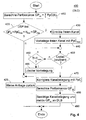
- eine schematische Darstellung eines individuellen Prozesses zur Verarbeitung einer Kanalneubelegungsanfrage;
- ist Fig. 5
- eine schematische Darstellung eines Prozesses zur Verarbeitung eines Codecwechsels; und
- ist Fig. 6
- eine schematische Darstellung eines Prozesses zur Freigabe eines Kanals.
- Die Figuren sind rein schematisch und nicht notwendigerweise maßstabsgetreu. Die zeichnerischen Darstellungen und Beschreibungen hiervon sind zur beispielhaften Veranschaulichung des Prinzips der Erfindung gedacht und sollen diese in keiner Weise einschränken.
- Wie in
Fig. 1 veranschaulicht, weist ein System 100 gemäß einem bevorzugten Ausführungsbeispiel der vorliegenden Erfindung vier digitale Signalprozessoren (nachstehend mit DSP abgekürzt) 111 (DSP1), 112 (DSP2), 113 (DSP3), 114 (DSP4), einen Host-Prozessor 120 und einen Speicher 150 auf. Ohne Beschränkung der Allgemeinheit ist in diesem Ausführungsbeispiel das System eine Gateway-Einrichtung in einem Telekommunikationsgerät und sind die digitalen Signalprozessoren 111-114, der Host-Prozessor 120 und der Speicher 150 auf der selben Platine untergebracht. Alternativ können die Komponenten auf unterschiedlichen Platinen untergebracht sein. Abweichend von dem Beispiel können der Host-Prozessor 120, der Speicher 150 und die digitalen Signalprozessoren 111-114 in verteilten Geräten implementiert sein. Insbesondere kann der Speicher 150 auf mehreren Platinen verteilt sein. - Zur Durchführung einer Kanalverwaltung von Sprachkommunikationskanälen (nachstehend kurz als Kanäle bezeichnet) auf den DSP 111-114 ist ein Host-Prozessor 120 vorgesehen. Der Host-Prozessor 120 weist einen zentralen Lastausgleichsprozess (nachstehend abgekürzt mit DLB oder DLB-Prozess für engl. "DSP Load Balancing process") 130 und für jeden im System vorhandenen DSP einen dedizierten DSP-Laststeuerungsprozess (nachstehend abgekürzt mit DLC bzw. DLC-Prozess für engl. "DSP Load Controller process") 141, 142, 143, 144 auf. Genauer gesagt, ist der DLC 141 (DLC 1) dem digitalen Signalprozessor 111 (DSP 1) zugeordnet, ist der DLC 142 (DLC 2) dem digitalen Signalprozessor 112 (DSP 2) zugeordnet, ist der DLC 143 (DLC 3) dem digitalen Signalprozessor 113 (DSP 3) zugeordnet, und ist der DLC 144 (DLC 4) dem digitalen Signalprozessor 114 (DSP 4) zugeordnet.
- Es versteht sich, dass die Anordnung mit vier DSPen ganz und gar beispielhaft ist. In bevorzugten Abwandlungen können weniger oder mehr DSPen im System vorhanden sein. Im Extrem ist die Erfindung auch auf einen einzigen DSP anwendbar.
- Der Speicher 150 weist einen DLB-Speicherbereich 160 und für jeden DLC (DLC1-DCL4) einen dedizierten DLC-Speicherbereich 171-174 auf. In dem DLB-Speicherbereich 160 ist eine Performance-Tabelle PT angelegt, die einen Auslastungszustand des Systems aus der Sicht des DLB-Prozesses 130 beschreibt. In jedem DLC-Speicherbereich 171-174 sind ein Bereich für Basisdaten BD und eine Kanalbelegungstabelle KT angelegt.
- Genauer gesagt, sind Basisdaten BD und eine Kanalbelegungstabelle KT für den DSP 111 (DSP1) im dedizierten Speicherbereich 171 hinterlegt, sind Basisdaten BD und eine Kanalbelegungstabelle KT für den DSP 112 (DSP2) im dedizierten Speicherbereich 172 hinterlegt, sind Basisdaten BD und eine Kanalbelegungstabelle KT für den DSP 113 (DSP3) im dedizierten Speicherbereich 173 hinterlegt, und sind Basisdaten BD und eine Kanalbelegungstabelle KT für den DSP 114 (DSP4) im dedizierten Speicherbereich 174 hinterlegt. Dabei beschreiben die Basisdaten BD eine Grundkonfiguration des durch den jeweiligen DLC gesteuerten DSP und beschreiben die Kanalbelegungstabellen KT einen Kanalbelegungszustand des jeweiligen DSP.
- In
Fig. 2 ist ein Anmeldeprozess für einen digitalen Signalprozessor, beispielsweise einen der digitalen Signalprozessoren 111-114 (Fig. 1 ), wie erdurch einen DSP-Laststeuerungsprozess (DLC), insbesondere jeden der DLCs 141-144 inFig. 1 , zur Anmeldung eines DSP an dem zentralen Lastausgleichsprozess DLB 130 vonFig. 1 gemäß dem bevorzugten Ausführungsbeispiel der vorliegenden Erfindung schematisch dargestellt. - Gemäß der Darstellung in
Fig. 2 weist der Anmeldeprozess 200 einen Bestimmungsschritt 210, einen Berechnungsschritt 220 und einen Meldeschritt 230 auf. - In dem Bestimmungsschritt 210 werden eine Gesamtperformance-Wertzahl GP des jeweiligen DSP, ein Performancebedarf PpC(i) (i=1...n) für jeden von n von dem DSP unterstützten Codecs sowie ein Hysteresebedarf HB des DSP bestimmt.
- Beispielsweise weist der erste DSP 111 (DSP1) von
Fig. 1 eine Gesamtperformance-Wertzahl GPmax=100 und einen Hysteresebedarf HB=2 auf und unterstützt die Codecs G.711, G.722, G.723, G.729 und T.38. Es sei ferner vorausgesetzt, dass die genannten Codecs einen Performancebedarf PpC gemäß nachstehender Tabelle 1 aufweisen:Tabelle 1: Performancebedarf verschiedener Codecs i Codec PpC 1 G.711 8 2 G.722 10 3 G.723 14 4 G.729 20 5 T.38 18 - Die Werte für GPmax sowie die unterstützten Codecs werden aus Datenblättern und/oder realen Messungen bestimmt und sind als Basisdaten BD im jeweiligen dedizierten Speicherbereich 171, ..., 174 abgelegt. Der Hysteresebedarf HB wird beispielsweise per Konfiguration festgelegt.
- In dem Berechnungsschritt 220 werden ein maximaler und ein minimaler Performancebedarf PpCmax, PpCmin und eine maximale Hysterese Hmax des DSP 111 (DSP1) berechnet, wobei die in Schritt 210 bestimmten Werte zur Berechnung herangezogen werden.
- Demnach werden für den DSP 111 (DSP1) der maximale Performancebedarf zu

der minimale Performancebedarf zu
und die maximale Hysterese zu
berechnet. - In dem Meldeschritt 230 werden die drei Parameter GPmax1=100, PpCmax1=20 und Hmax1=24 für den DSP 111 (DSP1) an den DLB gemeldet. Im Sinne der Erfindung ist die maximale Hysterese Hmax ein Sicherheitszuschlag und ist der Hysteresebedarf HB ein Erhöhungsfaktor, ist der Performancebedarf PpC ein Leistungsbedarf eines Codecs und ist die Gesamtperformance-Wertzahl GPmax ein maximales Gesamtleistungsvermögen eines DSP.
- Der Anmeldeprozess 200 wird in dem vorliegenden Ausführungsbeispiel in jedem der DLC 141-144 für den jeweils zugeordneten DSP 111-114 durchgeführt. So melden beispielsweise der DLC 142 (DLC2) für den DSP 112 (DSP2) die Werte GP2=200, PpCmax2=25 und Hmax2=30, der DLC 143 (DLC3) für den DSP 113 (DSP3) die Werte GP3=200, PpCmax3=25 und Hmax3=30, und der DLC 144 (DLC4) für den DSP 114 (DSP4) die Werte GP4=120, PpCmax4=10 und Hmax4=16 an den DLB 130.
- Die gemeldeten Werte werden in der Performancetabelle 160 (
Fig. 1 ) PT im DLB-Speicherbereich 160 des im Speicher 150 abgelegt. Nach der Anmeldung aller DSP 111-114, beispielsweise nach Hochlaufen des Systems weist die Performancetabelle beispielsweise folgende Werte auf:Tabelle 2: Performancetabelle nach Hochlauf DSP GPmax GPist GPinProc PpCmax Hmax 1 100 0 0 20 24 2 200 0 0 25 30 3 200 0 0 25 30 4 120 0 0 10 16 - Der maximale Performancebedarf PpCmax wird vorzugsweise ebenfalls in den Basisdaten BD des jeweiligen dedizierten Speicherbereichs 171, ..., 174 des Speichers 150 zur weiteren Verwendung abgelegt und dort von verschiedenen Prozessen des jeweiligen DLC 141, ..., 144 in Zugriff genommen. Alternativ ist es auch möglich, dass die Prozesse der DLC 141-144 auf die Performancetabelle PT im DLB-Speicherbereich 160 zugreifen; das würde Speicherplatz einsparen, kann aber zusätzlichen Aufwand in der Datenverwaltung, -zuordnung und -verarbeitung erfordern.
- Für die weitere Betrachtung wird davon ausgegangen, dass das System bereits einige Zeit läuft und einige Kanäle vermittelt werden. Beispielsweise wird der Zustand des Systems zu einem betrachteten Zeitpunkt durch die nachstehende Performancetabelle beschrieben:
Tabelle 3: Performancetabelle zu einem Betriebszeitpunkt DSP GPmax GPist GPinProc PpCmax Hmax 1 100 90 0 20 24 2 200 120 0 25 30 3 200 80 1 25 30 4 120 70 2 10 16 - In Tabelle 3 wie auch allen weiten Tabellen sind Werte, die sich gegenüber der jeweils nächstälteren Tabelle geändert haben, hervorgehoben.
- Gemäß Tabelle 3 wickelt somit im betrachteten Zeitpunkt DSP1 (111 in
Fig. 1 ) Kanäle mit einer Gesamtperformance (GPist) von 90 ab, wickelt DSP2 (112 inFig. 1 ) Kanäle mit einer Gesamtperformance von 120 ab, wickelt DSP3 (113 inFig. 1 ) Kanäle mit einer Gesamtperformance von 80 ab, und wickelt DSP4 (114 inFig. 1 ) Kanäle mit einer Gesamtperformance von 70 ab. Gleichzeitig bearbeitet der Laststeuerungsprozess DLC des DSP 3 gegenwärtig eine Anfrage zur Neubelegung eines Kanals (GPinProc) und bearbeitet der DLC des DSP 4 gegenwärtig zwei solche Anfragen. -
Fig. 3 veranschaulicht in Form eines Ablaufdiagramms einen im DLB durchgeführten Prozess 300 zur Bearbeitung einer neuen Kanalanforderung. - Eine solche Kanalanforderung wird zunächst an den DLB-Prozess geleitet. Demzufolge ist der Prozess 300 eine Unterroutine, die im laufenden DLB-Prozess aufgerufen wird, wenn eine neue Kanalanforderung an das System gestellt wird.
- Nach Beginn des Prozesses 300 werden in einem Schritt 310 freie DSPen ermittelt. Als freier DSP ist dabei ein DSP zu verstehen, dessen gegenwärtig gemeldete und in der Performancetabelle abgelegte Gesamtperformance unter Berücksichtigung der maximalen Hysterese und der gegenwärtig bearbeiteten und der neu hinzugekommenen Kanalanforderungen sowie des jeweiligen Performancebedarf geringer ist als die maximale Performance des jeweiligen DSP. Ein DSP gilt in diesem Verfahrensschritt somit als frei, wenn die Bedingung:

erfüllt ist. Die Berechnung in Schritt 310 kann in folgender Tabelle veranschaulicht werden:Tabelle 4: Berechnung freier DSPen DSP GP ist + H max + (GP inProc + 1) * PpC max Erg. GP max Erg. < GP max 1 90 + 24 + (0 + 1) * 20 134 100 false 2 120 + 30 + (0 + 1) * 25 175 200 true 3 80 + 30 + (1 + 1) * 25 160 200 true 4 70 + 16 + (2 + 1) * 10 116 120 true - In Schritt 320 wird beurteilt, ob es unter den vorhandenen DSPen wenigstens einen freien DSP gibt. Dies ist der Fall, wenn wenigstens eines der Berechnungsergebnisse true (wahr) ist. Falls die Beurteilung in Schritt 320 negativ ist (d.h., kein DSP ist frei), verzweigt der Prozess 300 zu Schritt 325, anderenfalls zu Schritt 330.
- In Schritt 325, der auf eine negative Beurteilung in Schritt 320 folgt, wird die Kanalanforderung zurückgewiesen, und danach endet der Prozess. Unter einem Enden des Prozesses ist im Allgemeinen ein Rücksprung in einen aufrufenden Prozess, hier insbesondere in den dem Prozess 300 übergeordneten DLB-Prozess, zu verstehen.
- In Schritt 330, der auf eine positive Beurteilung in Schritt 320 folgt, wird für alle in Schritt 310 als frei beurteilten DLP eine relative Lastreserve r nach der Beziehung

berechnet. Die Berechnung in Schritt 330 kann in folgender Tabelle veranschaulicht werden:Tabelle 5: Berechnung der relativen Lastreserve r DSP (GPmax - GPist - (GPinProc + 1) * PpCmax) / PpCmax Erg. = r 1 keine Berechnung n.n. 2 (200 - 120 - (0 + 1) * 25) / 25 2,2 3 (200 - 80 - (1 + 1) * 25) / 25 2,8 4 (120 - 70 (2 + 1) * 10) / 10 2 - In dem anschließenden Schritt 340 wird derjenige DSP bestimmt, der unter allen freien DSP die geringste Last aufweist. Hierzu wird die in Schritt 330 berechnete Lastreserve herangezogen. Die in Schritt 330 berechnete Lastreserve (es ist eine relative Lastreserve, die auf die maximale Last der von dem jeweiligen DSP unterstützten Codecs bezogen ist) ist ein Maß für die derzeitige Last (oder Auslastung) des jeweiligen DSP. Demnach wird im vorliegenden Beispiel DSP3 mit einer Lastreserve von 2,8 als der DSP mit der geringsten Last bestimmt.
- In dem anschließenden Schritt 350 wird die Performancetabelle aktualisiert, indem der Wert GPInProc für den in Schritt 340 bestimmten DSP mit der geringsten gegenwärtigen Last um "1" erhöht wird. D.h., der Wert GPInProc wird für den DSP3 um "1" inkrementiert. Nach Schritt 350 sieht die Performancetabelle wie folgt aus:
Tabelle 6: Performancetabelle nach Aktualisierung für Kanalanforderung DSP GP max GP ist GP inProc PpC max Hmax 1 100 90 0 20 24 2 200 120 0 25 30 3 200 80 2 25 30 4 120 70 2 10 16 - Wie in Tabelle 6 ersichtlich, hat sich der Wert GPInProc für den DSP3 von gegenüber Tabelle 3 von "1" auf "2" erhöht.
- In dem anschließenden Schritt 360 wird eine Kanalneubelegungsanfrage an den in Schritt 340 bestimmten DSP mit der geringsten Last bzw. der größten relativen Lastreserve r übermittelt. Im vorliegenden Beispiel wird demnach die Anfrage an DSP3 (r = 2,8) übermittelt.
- Danach endet dieser Prozess bzw. springt zum aufrufenden Prozess zurück.
-
Fig. 4 veranschaulicht in Form eines Ablaufdiagramms einen im DLC-Prozess durchgeführten Prozess 400 zur Bearbeitung einer Aufforderung bzw. Anfrage zur Belegung eines neuen Kanals (Aufbau eines Kommunikationskanals). - Der Prozess 400 ist eine Unterroutine, die im laufenden DLC-Prozess eines DLB aufgerufen wird, wenn durch den DLB-Prozess bzw. dessen Kanalanforderungsprozess 300 eine Kanalneubelegungsanfrage an diesen DLB weitergeleitet wird (vgl. Schritt 360 in
Fig. 3 ). Der Prozess 400 kann mehrfach, also für mehrere Anfragen, parallel aufgerufen werden. - Nach Beginn bzw. Aufruf des Prozesses 400 wird in Schritt 410 zunächst die tatsächliche gegenwärtige Performance GPist des zugehörigen DLB berechnet. Diese Berechnung kann durch die Beziehung

ausgedrückt werden, wobei k eine Laufvariable für die Summierung ist und K die Anzahl aller (belegten und freien) Kanäle im DSP ist. - Im gegenwärtigen Beispiel wurde durch den DLB (130 in
Fig. 1 ) in dem inFig. 3 veranschaulichten Prozess 300 der DSP3 als der DSP mit der geringsten Last ermittelt und daher die Kanalneubelegungsanfrage an den DSP3 weitergeleitet. für den DSP3 sei die gegenwärtige Kanalbelegung durch folgende Tabelle ausgedrückt:Tabelle 7: Kanalbelegung bei Aufruf des Prozesses 400 Kanal k 1 2 3 ... Codec G.723 (-) G.711 ... PpC 14 0 8 ... - Es sei angemerkt, dass die Kanalbelegungstabelle KT beide Zeilen "Codec" und "PpC" von Tabelle 7 aufweisen kann, aber nur eine der genannten Zeilen aufweisen muss, denn sowohl durch die Angabe des Codecs selbst als auch durch die Angabe der zugehörigen Performance PpC ist die Belegung eines Kanals eindeutig definiert. Es kann daher in der Kanalbelegungstabelle KT für jeden Kanal nur eine Kennung für den Codec abgelegt werden, wobei die Verknüpfung zwischen den Codecs und dem zugehörigen Performance-Wert in den Basisdaten BD des jeweiligen Speicherbereichs 171, ..., 174 (
Fig. 1 ) gegeben ist. Alternativ kann bei Belegung eines Kanals der Performance-Wert des vereinbarten Codec aus den Basisdaten BD geholt und in der Kanalbelegungstabelle KT abgelegt werden. Die Tabelle 7 wie auch weiter unten angegebene Tabellen zur Kanalbelegung dienen daher in erster Linie der Anschaulichtkeit und der Nachvollziehbarkeit des Zahlenbeispiels. Die Performance PpC jedes Kanals ist ein tatsächlicher Leistungsbedarf des Kanals im Sinne der Erfindung. - Die Formel 5, die in Schritt 410 zur Anwendung kommt, greift auf die Werte in Tabelle 7 zurück.
- In dem anschließenden Schritt 420 wird beurteilt, ob der DSP tatsächlich frei ist. Die Beurteilung in Schritt 420 ist positiv, wenn die Beziehung

erfüllt ist. - Falls die Beurteilung in Schritt 420 negativ ist, d.h., wenn beurteilt wird, dass der DSP nicht frei ist, verzweigt der Prozess zu Schritt 425, anderenfalls zu Schritt 430.
- In Schritt 425, der auf eine negative Beurteilung in Schritt 420 folgt, wird die Kanalanforderung zurückgewiesen, und der Prozess 400 endet.
- Es ist anzumerken, dass die Überprüfung durch Schritt 420 (einschließlich der Berechnung in Schritt 410) zu Beginn des Prozesses 400 durchgeführt wird, auch wenn in dem DLB-Kanalanforderungsprozess 300 (
Fig. 3 ) der DSP als frei ermittelt wurde. Der DLB-Kanalanforderungsprozess 300 (Fig. 3 ) greift auf die in der Performancetabelle bereits gemeldeten Daten zu. Es ist aber möglich, dass zwischenzeitlich eine Codec-Umschaltung in einem oder mehreren Kanälen des DSP erfolgte, die noch nicht an den DLB-Prozess gemeldet wurde. Daher kann sich der tatsächliche Performance-Wert GPist geändert (erhöht) haben, wodurch der DSP nicht mehr frei ist. Deshalb muss es auch auf dieser Ebene möglich sein, eine Kananeubelegungsanfrage zurückzuweisen. - In Schritt 430, der auf eine positive Beurteilung in Schritt 420 folgt, wird ein freier Kanal ermittelt. Dies kann jeder beliebige freie Kanal sein; wichtig ist nur, dass der Kanal in der Kanalbelegungstabelle eindeutig identifizierbar ist. Der in Schritt 430 ermittelte freie Kanal wird nachstehend als nominierter Kanal bezeichnet. In dem vorliegenden Zahlenbeispiel wird gemäß Tabelle 7 der Kanal Nr. 2 als frei ermittelt und nominiert.
- Im anschließenden Schritt 440 wird der in Schritt 430 nominierte Kanal zunächst mit dem maximalen Performance-Wert PpCmax vorbelegt. Für das vorliegende Zahlenbeispiel ergibt sich PpCmax für den angeforderten DSP3 aus der Performancetabelle PT (Tabelle 3) oder aus den Basisdaten BP für den DSP 3. Hiernach sieht die Kanalbelegung so aus, wie es in nachstehender Tabelle angegeben ist:
Tabelle 8: Kanalbelegung nach Vorbelegung Kanal k 1 2 3 ... Codec G.723 PpCmax G.711 ... PpC 14 20 8 ... - Wie aus Tabelle 8 ersichtlich, wurde der zuvor freie Kanal 2 durch den maximalen Performance-Wert PpCmax (= 20) vorbelegt.
- Im anschließenden Schritt 450 wird geprüft, ob der Codec für die Kanalanforderung bereits bestimmt ist. Dies erfolgt durch einen Empfang von Partnerdaten, also einer Gegenstelle des gewünschten Kommunikationskanals. Falls die Prüfung in Schritt 450 negativ ist, d.h., ein Codec für die Kanalanforderung noch nicht empfangen wurde, verzweigt der Prozess 400 zu Schritt 460, anderenfalls zu Schritt 470.
- In Schritt 460, der auf eine negative Prüfung in Schritt 450 folgt, wird geprüft, ob eine maximale Wartezeit Tmax verstrichen ist. Die Definition einer maximalen Wartezeit Tmax ist sinnvoll, um eine Endlosschleife, die zu einer dauerhaften Vorbelegung von Kanälen für obsolet gewordene Kanalanforderungen führen könnte, zu verhindern.
- Falls die Prüfung in Schritt 460 negativ ist, d.h., die maximale Wartezeit Tmax noch nicht verstrichen ist, springt der Prozess 400 zurück zur Prüfung in Schritt 450, um erneut zu prüfen, ob der Codec mittlerweile bestimmt ist.
- Falls die Prüfung in Schritt 460 positiv ist, d.h., die maximale Wartezeit Tmax verstrichen ist, verzweigt der Prozess 400 zu Schritt 465, um die Vorbelegung des nominierten Kanals nach Ablauf der maximalen Wartezeit Tmax zu löschen. Mit anderen Worten, in Schritt 465, der erreicht wird, wenn die maximale Wartezeit Tmax verstrichen ist, wird in der Kanalbelegungstabelle KT der Eintrag des Codecs für den nominierte Kanal gelöscht bzw. der Performance-Wert PpC für den nominierten Kanal auf den Wert "0" gesetzt. Danach springt der Prozess 400 zu Schritt 425, um die Kanalneubelegungsanfrage zurückzuweisen, und der Prozess 400 endet.
- In Schritt 470, der auf eine positive Prüfung in Schritt 450 folgt, wird die Kanalbelegung für den nominierten Kanal korrigiert. D.h., in die Kanalbelegungstabelle KT wird für den nominierten Kanal die Kennung für den bestimmten Codec und/oder der Performance-Wert PpC für den bestimmten Codec hinterlegt. Für das vorliegende Zahlenbeispiel werde angenommen, dass der bestimmte Codec G.723 sein soll. Daher sieht die Kanalbelegung nach Schritt 470 so aus, wie es in nachstehender Tabelle angegeben ist:
Tabelle 9: Kanalbelegung nach Korrektur Kanal k 1 2 3 ... Codec G.723 G.723 G.711 ... PpC 14 14 8 ... - Wie aus Tabelle 9 ersichtlich, wurde der zuvor mit PpCmax = 20 vorbelegte Kanal 2 nun durch Codec G.723 mit einem Performance-Wert PpC = 14 belegt.
- In dem anschließenden Schritt 480 wird der nun zutreffende Gesamtperformance-Wert GPist des DLB (DLB3 im vorliegenden Zahlenbeispiel) nach vorstehender Formel 6 berechnet. Danach wird in Schritt 490 die Kanalbelegung an den DLB-Prozess bestätigt und das in Schritt 480 berechnete GPist an den DLB-Prozess gemeldet. Danach endet der Prozess 400.
- Es ist darauf hinzuweisen, dass bei Zurückweisung der Kanalanforderung in Schritt 425 eine Neuberechnung und Meldung des tatsächlichen GPist unterbleibt, da eine Änderung der Gesamtperformance durch einen anderen Vorgang in einem entsprechenden Prozess berechnet und gemeldet werden kann.
- Obschon in der Figur nicht näher dargestellt, wird nach jedem Rücksprung des DLC-Prozesses der Wert GPinProc in der Performancetabelle PT für den gerade aufgerufenen DLB durch den DLB-Prozess um den Wert "1" erniedrigt, da die Bearbeitung für diese Kanalneubelegungsanfrage in dem DLC-Prozess abgeschlossen ist. Wurde die Kanalneubelegungsanfrage durch den DLC-Prozess bestätigt, ist diese Kanalanforderung auch im DLB-Prozess abgeschlossen. Wurde die Kanalneubelegungsanfrage dagegen zurückgewiesen, wird vorzugsweise der DLB-Kanalanforderungsprozess 300 (
Fig. 3 ) erneut aufgerufen. Alternativ kann, ggf. nach einer vorbestimmten Anzahl von Zurückweisungen durch DLC-Prozesse, die Kanalanforderung durch den DLB-Prozess endgültig zurückgewiesen werden. Es ist darauf hinzuweisen, dass die Begriffe der Kanalanforderung und der Kanalneubelegungsanfrage nur zur Unterscheidung der Bearbeitungsebene voneinander unterschieden werden. Eine Kanalanforderung an den zentralen DLB-Prozess wird als Kanalneubelegungsanfrage an einen dezentralen DLC-Prozess konkretisiert, und eine in dem dezentralen DLC-Prozess abgearbeitete Kanalneubelegungsanfrage betrifft eine bestimmte Kanalanforderung, die an den zentralen DLB-Prozess gerichtet worden war. - Der an den DLB-Prozess gemeldete, neue Wert für GPist des jeweiligen DLB wird im DLB-Prozess an die Stelle des alten Werts geschrieben. Somit erhält im vorliegenden Zahlenbeispiel die Performance-Tabelle folgenden Inhalt:
Tabelle 10: Performancetabelle nach Kanalbestätigung DSP GP max GP ist GPinProc PpCmax Hmax 1 100 90 0 20 24 2 200 120 0 25 30 3 200 94 1 25 30 4 120 70 2 10 16 -
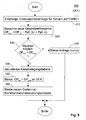
Fig. 5 veranschaulicht in Form eines Ablaufdiagramms einen im DLC-Prozess durchgeführten Prozess 500 für die Verarbeitung einer Anfrage zum Codecwechsel in einem DSP-Kanal. Für das Zahlenbeispiel sei angenommen, dass DSP3 betroffen ist und ein Kommunikationspartner der über den Kanal 3 durchgeführten Kommunikation einen Codecwechsel von G.711 auf G.729 wünscht. - Nach Start bzw. Aufruf des Prozesses 500 wird in Schritt 510 eine Anfrage empfangen, die einen Wechsel für einen Kanal k (hier: k = 3) von einem bisherigen Codec auf einen Codec i betrifft.
- In dem anschließenden Schritt 520 eine neue Gesamtperformance des betroffenen DSP unter Berücksichtigung des neuen Codec berechnet. Mit den Werten für das vorliegende Zahlenbeispiel (DSP3) wird diese Berechnung durch die Beziehung

ausgedrückt. - Im anschließenden Schritt 530 wird beurteilt, ob ein Kanalwechsel möglich ist. Diese Beurteilung ist positiv, wenn die Beziehung

wahr (true) ist. - Falls die Beurteilung in Schritt 530 negativ ist, verzweigt der Prozess 500 zu Schritt 535, anderenfalls zu Schritt 540.
- In Schritt 535, der auf eine negative Beurteilung in Schritt 530 folgt, wird der Codecwechsel zurückgewiesen, und der Prozess 500 endet.
- Für das Zahlenbeispiel (DSP3) ist der neue Wert für die Gesamtperformance GPneu=106 kleiner als die maximale Gesamtperformance GPmax=200, die Beurteilung in Schritt 530 ist daher positiv.
- In Schritt 540, der auf eine positive Beurteilung in Schritt 530 folgt, wird die Kanalbelegungstabelle für den betroffenen DSP aktualisiert. D.h., der Wert für den Codec bzw. dessen Performancebedarf wird in der Kanalbelegungstabelle KT mit dem neuen Codec bzw. dessen Performancebedarf überschrieben. Die Kanalbelegung wird danach durch folgende Tabelle ausgedrückt:
Tabelle 11: Kanalbelegung nach Codecwechsel Kanal k 1 2 3 ... Codec G.723 G.723 G.729 ... PpC 14 14 20 ... - Wie in Tabelle 11 ersichtlich, wurden die Werte für Kanal 3, die zuvor durch die Werte für G.711 belegt waren (vgl. Tabelle 9) durch die Werte für G.729 überschrieben. Falls die Gesamtperformance in den Basisdaten BD des DSP enthalten ist, wird dort der Wert GPist durch den neuen Wert GPneu überschrieben.
- Danach wird in Schritt 550 der neue Wert für GPist = GPneu an den DLB-Prozess gemeldet. Im DLB-Prozess wird, obschon in der Figur nicht näher dargestellt, die Performancetabelle mit dem neuen GPist für den meldenden DSP aktualisiert, wie es der nachstehenden Tabelle zu entnehmen ist:
Tabelle 13: Performancetabelle nach Codecwechsel DSP GPmax GPist GPinProc PpCmax Hmax 1 100 90 0 20 24 2 200 120 0 25 30 3 200 114 1 25 30 4 120 70 2 10 16 - Im anschließenden Schritt 560 wird der neue Codec an einen nicht näher dargestellten Kommunikationssteuerungsprozess. Danach endet der Prozess 500.
- Durch den oben angedeuteten Kommunikationssteuerungsprozess wird die Kommunikation auf dem Kanal k auf den neuen Codec i umgestellt. Die hierfür erforderlichen Prozesse wie etwa Handshake- und Signalinterpreterprozesse sind an sich bekannt und müssen hier nicht weiter beschrieben werden.
- Es ist anzumerken, dass der Prozess 500 im Wesentlichen in dem dedizierten DLC-Prozess 141, ..., 144 (vgl.
Fig. 1 ) und nicht im zentralen DLB-Prozess 130 abläuft. Durch diese dezentrale Verarbeitung werden nur dort prozessuale Ressourcen eingesetzt, wo sie gebraucht werden; die DLC-Prozesse, die anderen DSPen zugeordnet sind, und der zentrale DLB-Prozess 130 werden - abgesehen von der zentralen Aktualisierung der Performancetabelle - von Prozessen, die nur einen bestimmten DSP betreffen, nicht berührt. -
Fig. 6 veranschaulicht in Form eines Ablaufdiagramms einen Prozess 600 zur Freigabe eines Kanals. Der Prozess 600 ist Bestandteil des DLC-Prozesses und wird für einen bestimmten DSP dann durchgeführt, wenn eine über einen Kanal k des DSP geführte Kommunikation geendet hat. In diesem Fall sendet ein nicht näher dargestellter Kommunikationssteuerungsprozess eine Meldung über das Ende der Kommunikation in Kanal k an den DLC-Prozess des betroffenen DSP. Die Meldung kann auch über den DLB-Prozess empfangen und an den DLC-Prozess weitergeleitet werden. - Im vorliegenden Zahlenbeispiel wird angenommen, dass die Kommunikation in Kanal 2 des DSP3 geendet hat und eine entsprechende Meldung an den DLC-Prozess DLC3 des DSP3 gesendet wurde.
- Nach Beginn bzw. Aufruf des Prozesses 600 wird in Schritt 610 die Meldung über das Ende der Kommunikation in dem Kanal k empfangen.
- Sodann wird in Schritt 620 ein neuer Wert GPist,neu für den DSP berechnet, der sich aus dem Wegfall des Performancewerts PpC für den Kanal k ergibt. Die Berechnung folgt der nachstehenden Beziehung:

- Daraufhin wird in Schritt 630 die Kanalbelegungstabelle aktualisiert. D.h., der Wert für den Codec in Kanal k wird auf "0" gesetzt. Im vorliegenden Zahlenbeispiel (k=2) ergibt sich die Kanalbelegung nach Aktualisierung gemäß nachstehender Tabelle:
Tabelle 14: Kanalbelegung nach Kanalfreigabe Kanal k 1 2 3 ... Codec G.723 (-) G.729 ... PpC 14 0 20 ... - Wie in Tabelle 14 ersichtlich, wurden die Werte für Kanal 2, die zuvor durch die Werte für T.38 belegt waren (vgl. Tabelle 1) gelöscht. Falls die Gesamtperformance in den Basisdaten BD des DSP enthalten ist, wird dort der Wert GPist durch den neuen Wert GPist,neu überschrieben.
- Schließlich wird in Schritt 640 der neue Wert für GPist = GPist, neu an den DLB-Prozess gemeldet. Danach endet der Prozess 600.
- Im DLB-Prozess wird, obschon in der Figur nicht näher dargestellt, die Performancetabelle mit dem neuen GPist für den meldenden DSP aktualisiert, wie es der nachstehenden Tabelle zu entnehmen ist:
Tabelle 15: Performancetabelle nach Kanalfreigabe DSP GPmax GP ist GPinProc PpCmax Hmax 1 100 90 0 20 24 2 200 120 0 25 30 3 200 100 1 25 30 4 120 70 2 10 16 - Eine Zurückweisung eines Codecwechsel in Schritt 535 (
Fig. 5 ) bedeutet, dass der Hysteresebedarf für den DSP zu gering angenommen wurde. In einem hier nicht weiter beschriebenen oder dargestellen Prozess können Zurückweisungen von Codecwechseln beobachtet werden und kann der Hysteresebedarf ggf. erhöht werden, wenn eine Zurückweisung sehr oft vorkommt. Ebenso ist es denkbar, einen Prozess vorzusehen, der bei häufigen Zurückweisungen von Kanalbelegungsanforderungen in Schritt 325 (Fig. 3 ) den Hysteresebedarf für alle oder einzelne DSPen verringert. - Nach einer Zurückweisung eines Codecwechsels kann der DLB-Prozess versuchen, durch Ausführen des Prozesses 300 gemäß
Fig. 3 einen freien DSP zu finden und die den Codecwechsel anfordernde Kommunikationsverbindung mit dem neu angeforderten Codec auf einen anderen DSP zu verteilen. -
- 100
- System
- 111-114
- Digitale Signalprozessoren DSP1 - DSP4
- 120
- Host-Prozessor
- 130
- DSP-Lastausgleichsprozess (DLB-Prozess)
- 141-144
- DSP-Laststeuerungsprozesse (DLC-Prozesse) DLC1 - DLC 4
- 150
- Speicher
- 160
- DLB-Speicherbereich
- 171-174
- DLC-Speicherbereiche
- 200
- DLC-Meldeprozess (2xx: Prozess-Schritte)
- 300
- DLB-Kanalanforderungsprozess (3xx: Prozess-Schritte)
- 400
- DLC-Kanalanforderungsprozess (4xx: Prozess-Schritte)
- 500
- DLC-Kanalwechselprozess (5xx: Prozess-Schritte)
- 600
- DLC-Kanalfreigabeprozess (6xx: Prozess-Schritte)
- i
- Laufvariable für Codecs
- k
- Laufvariable für Kanäle
- n
- Anzahl von unterstützten Codecs in einem DSP
- r
- relative Lastreserve
- BD
- Basisdaten
- DLB
- DSP-Lastausgleich (DSP Load Balancing)
- DLC
- DSP-Laststeuerung (DSP Load Control)
- DSP
- Digitaler Signalprozessor
- GP
- Gesamtperformance
- GPist
- Gesamtperformance eines DSP
- GPmax
- maximale Gesamtperformance eines DSP
- Hmax
- maximale Hysterese eines DSP
- HB
- Hysteresebedarf eines DSP
- K
- Anzahl der Kanäle in einem DSP
- KT
- Kanalbelegungstabelle
- PpC
- Performancebedarf eines Codec (Performance per Codex)
- PpCmax
- maximaler Performancebedarf eines DSP
- PpCmin
- minimaler Performancebedarf eines DSP
- PT
- Performancetabelle
- Die vorstehende Liste ist integraler Bestandteil der Beschreibung.
Claims (10)
- Verfahren zur Kanalverwaltung auf digitalen Signalprozessoren, dadurch gekennzeichnet, dass die Kanalverwaltung zu jedem Zeitpunkt anhand einer momentanen Auslastung jedes digitalen Signalprozessors unter Berücksichtigung eines tatsächlichen Leistungsbedarfs jedes Kanals und eines maximalen Gesamtleistungsvermögens jedes digitalen Signalprozessors erfolgt.
- Verfahren gemäß Anspruch 1, dadurch gekennzeichnet, dass bei der Ermittlung der Auslastung eines betrachteten digitalen Signalprozessors ein Sicherheitszuschlag zur tatsächlichen Beanspruchung durch gegenwärtig belegte oder zu belegende Kanäle berücksichtigt wird.
- Verfahren gemäß Anspruch 2, dadurch gekennzeichnet, dass der Sicherheitszuschlag aus einer Differenz eines maximalen Leistungsbedarfs und eines minimalen Leistungsbedarfs aller von dem betrachteten digitalen Signalprozessor unterstützten Codecs und einem Erhöhungsfaktor berechnet wird.
- Verfahren gemäß Anspruch 3, dadurch gekennzeichnet, dass der Erhöhungsfaktor, die Leistungsbedarfswerte der unterstützten Codecs und das maximale Gesamtleistungsvermögen vorab für jeden digitalen Signalprozessor bestimmt werden.
- Verfahren gemäß Anspruch 1, dadurch gekennzeichnet, dass die Kanalverwaltung durch eine zentrale Instanz und eine Mehrzahl von dezentralen Instanzen durchgeführt wird, wobei jede dezentrale Instanz einem digitalen Signalprozessor individuell zugeordnet ist.
- Verfahren gemäß Anspruch 5, dadurch gekennzeichnet, dass die dezentralen Instanzen eingerichtet und ausgelegt sind, um Leistungsdaten des ihr zugeordneten digitalen Signalprozessors an die zentrale Instanz weiterzugeben.
- Verfahren gemäß Anspruch 5 oder 6, dadurch gekennzeichnet, dass die dezentralen Instanzen durch die zentrale Instanz anforderbar sind.
- Verfahren gemäß Anspruch 1, dadurch gekennzeichnet, dass das Verfahren die durch eine zentrale Instanz durchzuführenden Schritte aufweist:- Empfangen einer Kanalanforderung;- Bestimmen von digitalen Signalprozessoren, die für eine Kanalneubelegung zur Verfügung stehen, als freie digitalen Signalprozessoren, auf der Grundlage einer ersten Beziehung für jeden digitalen Signalprozessor zwischen einer momentanen Auslastung, eines maximalen Gesamtleistungsvermögens und eines Leistungsbedarfs gegenwärtig an den digitalen Signalprozessor gerichteten Kanalneubelegungsanfragen, wobei die erste Beziehung vorzugsweise einen Sicherheitszuschlag aufweist; und- falls die Bestimmung freier digitalen Signalprozessoren ergibt, dass kein digitaler Signalprozessor frei ist, Zurückweisen der Kanalanforderung, oder- anderenfalls, Bestimmen desjenigen digitalen Signalprozessors, der unter allen freien digitalen Signalprozessoren eine geringste momentane Auslastung aufweist, als nominierten digitalen Signalprozessor, auf der Grundlage einer zweiten Beziehung für jeden freien digitalen Signalprozessor zwischen einer momentanen Auslastung, eines maximalen Gesamtleistungsvermögens und eines Leistungsbedarfs gegenwärtig an den digitalen Signalprozessor gerichteten Kanalneubelegungsanfragen, wobei jeweils der Leistungsbedarf einer Kanalneubelegungsanfrage vorzugsweise auf der Grundlage des größten Leistungsbedarfs unter allen von dem digitalen Signalprozessor unterstützten Codecs bestimmt wird, und Richten einer Kanalneubelegungsanfrage an eine dezentrale Instanz, die dem nominierten digitalen Signalprozessor zugeordnet ist.
- Verfahren gemäß Anspruch 8, dadurch gekennzeichnet, dass das Verfahren die durch eine dezentrale Instanz durchzuführenden Schritte aufweist:- Empfangen einer Kanalneubelegungsanfrage von der zentralen Instanz;- Prüfen, ob ein Kanal des digitalen Signalprozessors frei ist, auf der Grundlage einer dritten Beziehung zwischen einer momentanen Auslastung, einem maximalen Gesamtleistungsvermögen und einem größten Leistungsbedarf aller von dem digitalen Signalprozessor unterstützten Codecs, wobei die dritte Beziehung vorzugsweise einen Sicherheitszuschlag aufweist; und- falls kein Kanal frei ist, Zurückweisen der Kanalneubelegungsanfrage, oder- anderenfalls, Bestätigen der Kanalneubelegungsanfrage, wenn ein Kanal frei ist, oder an die zentrale Instanz, wobei vorzugsweise zusätzlich die momentanen Auslastung unter Berücksichtigung des tatsächlichen Leistungsbedarfs für einen angeforderten Codec neu berechnet und an die zentrale Instanz gemeldet wird.
- Vorrichtung zur Kanalverwaltung auf digitalen Signalprozessoren, dadurch gekennzeichnet, dass die Vorrichtung zur Durchführung eines Verfahrens nach einem der vorstehenden Ansprüche eingerichtet und ausgelegt ist.
Applications Claiming Priority (1)
| Application Number | Priority Date | Filing Date | Title |
|---|---|---|---|
| DE102012024881.4A DE102012024881B4 (de) | 2012-12-19 | 2012-12-19 | Verfahren und Vorrichtung zum Steuern von DSP-Kanälen |
Publications (3)
| Publication Number | Publication Date |
|---|---|
| EP2746945A2 true EP2746945A2 (de) | 2014-06-25 |
| EP2746945A3 EP2746945A3 (de) | 2016-08-17 |
| EP2746945B1 EP2746945B1 (de) | 2020-01-22 |
Family
ID=49886558
Family Applications (1)
| Application Number | Title | Priority Date | Filing Date |
|---|---|---|---|
| EP13005731.8A Active EP2746945B1 (de) | 2012-12-19 | 2013-12-09 | Verfahren und Vorrichtung zum Steuern von DSP-Kanälen |
Country Status (3)
| Country | Link |
|---|---|
| US (3) | US9438518B2 (de) |
| EP (1) | EP2746945B1 (de) |
| DE (1) | DE102012024881B4 (de) |
Families Citing this family (2)
| Publication number | Priority date | Publication date | Assignee | Title |
|---|---|---|---|---|
| US10225290B2 (en) * | 2016-07-15 | 2019-03-05 | Genband Us Llc | Systems and methods for extending DSP capability of existing computing devices |
| CN115065911A (zh) * | 2022-06-13 | 2022-09-16 | 中国第一汽车股份有限公司 | 一种音频控制系统、音频控制方法、装置、设备及介质 |
Family Cites Families (10)
| Publication number | Priority date | Publication date | Assignee | Title |
|---|---|---|---|---|
| WO1996032710A1 (en) * | 1995-04-10 | 1996-10-17 | Corporate Computer Systems, Inc. | System for compression and decompression of audio signals for digital transmission |
| US6104721A (en) * | 1997-12-02 | 2000-08-15 | Symmetry Communcations System | DSP based dynamic resource allocation multiprocessor communications board |
| US6338130B1 (en) * | 1999-03-11 | 2002-01-08 | International Business Machines Corporation | Adaptive method and apparatus for allocation of DSP resources in a communication system |
| US6925641B1 (en) * | 2000-02-04 | 2005-08-02 | Xronix Communications, Inc. | Real time DSP load management system |
| US7379877B2 (en) * | 2001-09-13 | 2008-05-27 | Nokia Corporation | Signal processing device and signal processing method |
| US7929441B1 (en) * | 2003-08-20 | 2011-04-19 | Cisco Technology, Inc. | Resource reservation method and system |
| KR100546780B1 (ko) * | 2003-12-26 | 2006-01-25 | 한국전자통신연구원 | 다수의 DSP를 사용하는 VoP(Voice OverPacket)시스템 및 그 시스템에서의 음성 처리 방법 |
| CN100588190C (zh) * | 2004-09-29 | 2010-02-03 | 上海贝尔阿尔卡特股份有限公司 | 基带板及其处理多标准业务的方法 |
| EP1705858A1 (de) * | 2005-03-24 | 2006-09-27 | Orange SA | Verfahren und System zur Aktivierung eines Kontextes für ein Paketdatenprotokoll |
| US8171484B2 (en) * | 2006-11-17 | 2012-05-01 | Fujitsu Limited | Resource management apparatus and radio network controller |
-
2012
- 2012-12-19 DE DE102012024881.4A patent/DE102012024881B4/de active Active
-
2013
- 2013-12-09 EP EP13005731.8A patent/EP2746945B1/de active Active
- 2013-12-11 US US14/103,149 patent/US9438518B2/en active Active
-
2016
- 2016-07-27 US US15/220,566 patent/US9614769B2/en active Active
-
2017
- 2017-02-22 US US15/439,135 patent/US9729453B2/en active Active
Non-Patent Citations (1)
| Title |
|---|
| None |
Also Published As
| Publication number | Publication date |
|---|---|
| DE102012024881A1 (de) | 2014-06-26 |
| EP2746945B1 (de) | 2020-01-22 |
| EP2746945A3 (de) | 2016-08-17 |
| DE102012024881B4 (de) | 2021-04-01 |
| US20170163541A1 (en) | 2017-06-08 |
| US9438518B2 (en) | 2016-09-06 |
| US9729453B2 (en) | 2017-08-08 |
| US20140169165A1 (en) | 2014-06-19 |
| US20160337246A1 (en) | 2016-11-17 |
| US9614769B2 (en) | 2017-04-04 |
Similar Documents
| Publication | Publication Date | Title |
|---|---|---|
| DE69924985T2 (de) | Lastausgleich von bestehenden anrufen zwischen unterschiedlichen basisstations-steuereinheiten | |
| DE60318468T2 (de) | Verfahren zur lösung von entscheidungslosigkeiten in einem cluster-rechnersystem | |
| DE69821243T2 (de) | Rekonfigurierung eines zellularen telefonnetzes | |
| WO2013178270A1 (de) | Zugriff von clients auf einen serverdienst mittels einer opc-ua | |
| DE102014213304A1 (de) | Verfahren und Vorrichtungen zum Überwachen bzw. Einstellen einer Dienstgüte von einer Datenübertragung über eine Datenverbindung in einem Funknetzwerk | |
| DE102004059145B3 (de) | Präsenz-Server-Einheit, Verfahren zum Steuern einer Präsenz-Server-Einheit, Kommunikationsanordnung, Verfahren zum Betreiben einer Kommunikationsanordnung | |
| DE102004019987A1 (de) | Aufbau einer Transcoder-freien-Operations-Verbindung | |
| DE10260351A1 (de) | Lastverteilungssystem für die Steuervorrichtung einer Basisstation | |
| EP2746945B1 (de) | Verfahren und Vorrichtung zum Steuern von DSP-Kanälen | |
| DE102004057496B4 (de) | Verfahren und Vorrichtung zur automatischen Neueinstellung von Grenzen für Zugangskontrollen zur Beschränkung des Verkehrs in einem Kommunikationsnetz | |
| EP1979198A1 (de) | Verfahren und system zur dynamischen ressourcenzuweisung | |
| EP1472900B1 (de) | Verfahren zur weiterführung einer kommunikationsverbindung unter einbeziehung mehrerer funk-kommunikationssysteme | |
| WO2005067223A1 (de) | Verfahren zur bestimmung von grenzwerten für eine verkehrskontrolle in kommunikationsnetzen mit zugangskontrolle | |
| DE69833124T2 (de) | Adaptives prozessorsystem | |
| DE112017008163T5 (de) | Überwachungsvorrichtung und Überwachungssystem | |
| DE60222305T2 (de) | Verfahren und netzwerkknoten zur auswahl eines kombinationsknotens | |
| DE102018208768A1 (de) | Hinzufügung einer kommunikationssitzung über einen host im denynew-service-modus | |
| EP1668866B1 (de) | Überprüfung der verfügbarkeit eines servers | |
| EP1460798B1 (de) | Verfahren und Kommunikationssystem zum Abbrechen von Management-Operationen in einem Managementnetz | |
| DE112020007348T5 (de) | Verfahren und system zur ausführung eines byzantine-fault-tolerant- bzw. bft-protokolls | |
| DE102020003281A1 (de) | Verfahren zum Betreiben eines Systems für eine Vielzahl von Kraftfahrzeugen, sowie System | |
| EP1925134B1 (de) | Verfahren zur reservierung von bandbreite | |
| DE10311697A1 (de) | Verfahren zum Abbrechen von Management-Operationen in einem Managementnetz und Kommunikationssystem | |
| DE102004009266A1 (de) | Verfahren zur Übertragung von Nutzdaten in einem Multihop-System und Netzwerkknoten-Einrichtung dafür | |
| EP1730921B1 (de) | Verfahren zum verwalten von presenzdaten einer gruppe von telekommunikatonsteilnehmern und vorrichtung zur durchfuehrung des verfahrens |
Legal Events
| Date | Code | Title | Description |
|---|---|---|---|
| PUAI | Public reference made under article 153(3) epc to a published international application that has entered the european phase |
Free format text: ORIGINAL CODE: 0009012 |
|
| 17P | Request for examination filed |
Effective date: 20131209 |
|
| AK | Designated contracting states |
Kind code of ref document: A2 Designated state(s): AL AT BE BG CH CY CZ DE DK EE ES FI FR GB GR HR HU IE IS IT LI LT LU LV MC MK MT NL NO PL PT RO RS SE SI SK SM TR |
|
| AX | Request for extension of the european patent |
Extension state: BA ME |
|
| PUAL | Search report despatched |
Free format text: ORIGINAL CODE: 0009013 |
|
| AK | Designated contracting states |
Kind code of ref document: A3 Designated state(s): AL AT BE BG CH CY CZ DE DK EE ES FI FR GB GR HR HU IE IS IT LI LT LU LV MC MK MT NL NO PL PT RO RS SE SI SK SM TR |
|
| AX | Request for extension of the european patent |
Extension state: BA ME |
|
| RIC1 | Information provided on ipc code assigned before grant |
Ipc: G06F 9/50 20060101AFI20160714BHEP |
|
| RAP1 | Party data changed (applicant data changed or rights of an application transferred) |
Owner name: UNIFY GMBH & CO. KG |
|
| STAA | Information on the status of an ep patent application or granted ep patent |
Free format text: STATUS: REQUEST FOR EXAMINATION WAS MADE |
|
| R17P | Request for examination filed (corrected) |
Effective date: 20170217 |
|
| RBV | Designated contracting states (corrected) |
Designated state(s): AL AT BE BG CH CY CZ DE DK EE ES FI FR GB GR HR HU IE IS IT LI LT LU LV MC MK MT NL NO PL PT RO RS SE SI SK SM TR |
|
| STAA | Information on the status of an ep patent application or granted ep patent |
Free format text: STATUS: EXAMINATION IS IN PROGRESS |
|
| 17Q | First examination report despatched |
Effective date: 20180403 |
|
| GRAP | Despatch of communication of intention to grant a patent |
Free format text: ORIGINAL CODE: EPIDOSNIGR1 |
|
| STAA | Information on the status of an ep patent application or granted ep patent |
Free format text: STATUS: GRANT OF PATENT IS INTENDED |
|
| INTG | Intention to grant announced |
Effective date: 20190821 |
|
| GRAS | Grant fee paid |
Free format text: ORIGINAL CODE: EPIDOSNIGR3 |
|
| GRAA | (expected) grant |
Free format text: ORIGINAL CODE: 0009210 |
|
| STAA | Information on the status of an ep patent application or granted ep patent |
Free format text: STATUS: THE PATENT HAS BEEN GRANTED |
|
| AK | Designated contracting states |
Kind code of ref document: B1 Designated state(s): AL AT BE BG CH CY CZ DE DK EE ES FI FR GB GR HR HU IE IS IT LI LT LU LV MC MK MT NL NO PL PT RO RS SE SI SK SM TR |
|
| REG | Reference to a national code |
Ref country code: GB Ref legal event code: FG4D Free format text: NOT ENGLISH |
|
| REG | Reference to a national code |
Ref country code: CH Ref legal event code: EP |
|
| REG | Reference to a national code |
Ref country code: AT Ref legal event code: REF Ref document number: 1227358 Country of ref document: AT Kind code of ref document: T Effective date: 20200215 |
|
| REG | Reference to a national code |
Ref country code: IE Ref legal event code: FG4D Free format text: LANGUAGE OF EP DOCUMENT: GERMAN |
|
| REG | Reference to a national code |
Ref country code: DE Ref legal event code: R096 Ref document number: 502013014228 Country of ref document: DE |
|
| RAP2 | Party data changed (patent owner data changed or rights of a patent transferred) |
Owner name: UNIFY GMBH & CO. KG |
|
| REG | Reference to a national code |
Ref country code: NL Ref legal event code: MP Effective date: 20200122 |
|
| REG | Reference to a national code |
Ref country code: LT Ref legal event code: MG4D |
|
| PG25 | Lapsed in a contracting state [announced via postgrant information from national office to epo] |
Ref country code: RS Free format text: LAPSE BECAUSE OF FAILURE TO SUBMIT A TRANSLATION OF THE DESCRIPTION OR TO PAY THE FEE WITHIN THE PRESCRIBED TIME-LIMIT Effective date: 20200122 Ref country code: FI Free format text: LAPSE BECAUSE OF FAILURE TO SUBMIT A TRANSLATION OF THE DESCRIPTION OR TO PAY THE FEE WITHIN THE PRESCRIBED TIME-LIMIT Effective date: 20200122 Ref country code: NO Free format text: LAPSE BECAUSE OF FAILURE TO SUBMIT A TRANSLATION OF THE DESCRIPTION OR TO PAY THE FEE WITHIN THE PRESCRIBED TIME-LIMIT Effective date: 20200422 Ref country code: PT Free format text: LAPSE BECAUSE OF FAILURE TO SUBMIT A TRANSLATION OF THE DESCRIPTION OR TO PAY THE FEE WITHIN THE PRESCRIBED TIME-LIMIT Effective date: 20200614 Ref country code: NL Free format text: LAPSE BECAUSE OF FAILURE TO SUBMIT A TRANSLATION OF THE DESCRIPTION OR TO PAY THE FEE WITHIN THE PRESCRIBED TIME-LIMIT Effective date: 20200122 |
|
| PG25 | Lapsed in a contracting state [announced via postgrant information from national office to epo] |
Ref country code: BG Free format text: LAPSE BECAUSE OF FAILURE TO SUBMIT A TRANSLATION OF THE DESCRIPTION OR TO PAY THE FEE WITHIN THE PRESCRIBED TIME-LIMIT Effective date: 20200422 Ref country code: SE Free format text: LAPSE BECAUSE OF FAILURE TO SUBMIT A TRANSLATION OF THE DESCRIPTION OR TO PAY THE FEE WITHIN THE PRESCRIBED TIME-LIMIT Effective date: 20200122 Ref country code: IS Free format text: LAPSE BECAUSE OF FAILURE TO SUBMIT A TRANSLATION OF THE DESCRIPTION OR TO PAY THE FEE WITHIN THE PRESCRIBED TIME-LIMIT Effective date: 20200522 Ref country code: GR Free format text: LAPSE BECAUSE OF FAILURE TO SUBMIT A TRANSLATION OF THE DESCRIPTION OR TO PAY THE FEE WITHIN THE PRESCRIBED TIME-LIMIT Effective date: 20200423 Ref country code: HR Free format text: LAPSE BECAUSE OF FAILURE TO SUBMIT A TRANSLATION OF THE DESCRIPTION OR TO PAY THE FEE WITHIN THE PRESCRIBED TIME-LIMIT Effective date: 20200122 Ref country code: LV Free format text: LAPSE BECAUSE OF FAILURE TO SUBMIT A TRANSLATION OF THE DESCRIPTION OR TO PAY THE FEE WITHIN THE PRESCRIBED TIME-LIMIT Effective date: 20200122 |
|
| REG | Reference to a national code |
Ref country code: DE Ref legal event code: R097 Ref document number: 502013014228 Country of ref document: DE |
|
| PG25 | Lapsed in a contracting state [announced via postgrant information from national office to epo] |
Ref country code: SK Free format text: LAPSE BECAUSE OF FAILURE TO SUBMIT A TRANSLATION OF THE DESCRIPTION OR TO PAY THE FEE WITHIN THE PRESCRIBED TIME-LIMIT Effective date: 20200122 Ref country code: ES Free format text: LAPSE BECAUSE OF FAILURE TO SUBMIT A TRANSLATION OF THE DESCRIPTION OR TO PAY THE FEE WITHIN THE PRESCRIBED TIME-LIMIT Effective date: 20200122 Ref country code: CZ Free format text: LAPSE BECAUSE OF FAILURE TO SUBMIT A TRANSLATION OF THE DESCRIPTION OR TO PAY THE FEE WITHIN THE PRESCRIBED TIME-LIMIT Effective date: 20200122 Ref country code: RO Free format text: LAPSE BECAUSE OF FAILURE TO SUBMIT A TRANSLATION OF THE DESCRIPTION OR TO PAY THE FEE WITHIN THE PRESCRIBED TIME-LIMIT Effective date: 20200122 Ref country code: DK Free format text: LAPSE BECAUSE OF FAILURE TO SUBMIT A TRANSLATION OF THE DESCRIPTION OR TO PAY THE FEE WITHIN THE PRESCRIBED TIME-LIMIT Effective date: 20200122 Ref country code: LT Free format text: LAPSE BECAUSE OF FAILURE TO SUBMIT A TRANSLATION OF THE DESCRIPTION OR TO PAY THE FEE WITHIN THE PRESCRIBED TIME-LIMIT Effective date: 20200122 Ref country code: SM Free format text: LAPSE BECAUSE OF FAILURE TO SUBMIT A TRANSLATION OF THE DESCRIPTION OR TO PAY THE FEE WITHIN THE PRESCRIBED TIME-LIMIT Effective date: 20200122 Ref country code: EE Free format text: LAPSE BECAUSE OF FAILURE TO SUBMIT A TRANSLATION OF THE DESCRIPTION OR TO PAY THE FEE WITHIN THE PRESCRIBED TIME-LIMIT Effective date: 20200122 |
|
| PLBE | No opposition filed within time limit |
Free format text: ORIGINAL CODE: 0009261 |
|
| STAA | Information on the status of an ep patent application or granted ep patent |
Free format text: STATUS: NO OPPOSITION FILED WITHIN TIME LIMIT |
|
| REG | Reference to a national code |
Ref country code: DE Ref legal event code: R082 Ref document number: 502013014228 Country of ref document: DE Representative=s name: SCHAAFHAUSEN PATENTANWAELTE PARTNERSCHAFTSGESE, DE |
|
| 26N | No opposition filed |
Effective date: 20201023 |
|
| PG25 | Lapsed in a contracting state [announced via postgrant information from national office to epo] |
Ref country code: IT Free format text: LAPSE BECAUSE OF FAILURE TO SUBMIT A TRANSLATION OF THE DESCRIPTION OR TO PAY THE FEE WITHIN THE PRESCRIBED TIME-LIMIT Effective date: 20200122 |
|
| PG25 | Lapsed in a contracting state [announced via postgrant information from national office to epo] |
Ref country code: SI Free format text: LAPSE BECAUSE OF FAILURE TO SUBMIT A TRANSLATION OF THE DESCRIPTION OR TO PAY THE FEE WITHIN THE PRESCRIBED TIME-LIMIT Effective date: 20200122 Ref country code: PL Free format text: LAPSE BECAUSE OF FAILURE TO SUBMIT A TRANSLATION OF THE DESCRIPTION OR TO PAY THE FEE WITHIN THE PRESCRIBED TIME-LIMIT Effective date: 20200122 |
|
| REG | Reference to a national code |
Ref country code: CH Ref legal event code: PL |
|
| PG25 | Lapsed in a contracting state [announced via postgrant information from national office to epo] |
Ref country code: MC Free format text: LAPSE BECAUSE OF FAILURE TO SUBMIT A TRANSLATION OF THE DESCRIPTION OR TO PAY THE FEE WITHIN THE PRESCRIBED TIME-LIMIT Effective date: 20200122 |
|
| REG | Reference to a national code |
Ref country code: BE Ref legal event code: MM Effective date: 20201231 |
|
| PG25 | Lapsed in a contracting state [announced via postgrant information from national office to epo] |
Ref country code: LU Free format text: LAPSE BECAUSE OF NON-PAYMENT OF DUE FEES Effective date: 20201209 Ref country code: IE Free format text: LAPSE BECAUSE OF NON-PAYMENT OF DUE FEES Effective date: 20201209 |
|
| PG25 | Lapsed in a contracting state [announced via postgrant information from national office to epo] |
Ref country code: LI Free format text: LAPSE BECAUSE OF NON-PAYMENT OF DUE FEES Effective date: 20201231 Ref country code: CH Free format text: LAPSE BECAUSE OF NON-PAYMENT OF DUE FEES Effective date: 20201231 |
|
| REG | Reference to a national code |
Ref country code: AT Ref legal event code: MM01 Ref document number: 1227358 Country of ref document: AT Kind code of ref document: T Effective date: 20201209 |
|
| PG25 | Lapsed in a contracting state [announced via postgrant information from national office to epo] |
Ref country code: AT Free format text: LAPSE BECAUSE OF NON-PAYMENT OF DUE FEES Effective date: 20201209 |
|
| PG25 | Lapsed in a contracting state [announced via postgrant information from national office to epo] |
Ref country code: TR Free format text: LAPSE BECAUSE OF FAILURE TO SUBMIT A TRANSLATION OF THE DESCRIPTION OR TO PAY THE FEE WITHIN THE PRESCRIBED TIME-LIMIT Effective date: 20200122 Ref country code: MT Free format text: LAPSE BECAUSE OF FAILURE TO SUBMIT A TRANSLATION OF THE DESCRIPTION OR TO PAY THE FEE WITHIN THE PRESCRIBED TIME-LIMIT Effective date: 20200122 Ref country code: CY Free format text: LAPSE BECAUSE OF FAILURE TO SUBMIT A TRANSLATION OF THE DESCRIPTION OR TO PAY THE FEE WITHIN THE PRESCRIBED TIME-LIMIT Effective date: 20200122 |
|
| PG25 | Lapsed in a contracting state [announced via postgrant information from national office to epo] |
Ref country code: MK Free format text: LAPSE BECAUSE OF FAILURE TO SUBMIT A TRANSLATION OF THE DESCRIPTION OR TO PAY THE FEE WITHIN THE PRESCRIBED TIME-LIMIT Effective date: 20200122 Ref country code: AL Free format text: LAPSE BECAUSE OF FAILURE TO SUBMIT A TRANSLATION OF THE DESCRIPTION OR TO PAY THE FEE WITHIN THE PRESCRIBED TIME-LIMIT Effective date: 20200122 |
|
| PG25 | Lapsed in a contracting state [announced via postgrant information from national office to epo] |
Ref country code: BE Free format text: LAPSE BECAUSE OF NON-PAYMENT OF DUE FEES Effective date: 20201231 |
|
| REG | Reference to a national code |
Ref country code: DE Ref legal event code: R081 Ref document number: 502013014228 Country of ref document: DE Owner name: UNIFY BETEILIGUNGSVERWALTUNG GMBH & CO. KG, DE Free format text: FORMER OWNER: UNIFY GMBH & CO. KG, 80807 MUENCHEN, DE |
|
| REG | Reference to a national code |
Ref country code: GB Ref legal event code: 732E Free format text: REGISTERED BETWEEN 20250807 AND 20250813 |
|
| PGFP | Annual fee paid to national office [announced via postgrant information from national office to epo] |
Ref country code: FR Payment date: 20250930 Year of fee payment: 13 |
|
| REG | Reference to a national code |
Ref country code: GB Ref legal event code: 732E Free format text: REGISTERED BETWEEN 20251106 AND 20251112 |
|
| PGFP | Annual fee paid to national office [announced via postgrant information from national office to epo] |
Ref country code: DE Payment date: 20250930 Year of fee payment: 13 |
|
| PGFP | Annual fee paid to national office [announced via postgrant information from national office to epo] |
Ref country code: GB Payment date: 20251001 Year of fee payment: 13 |