EP2745675B2 - Weighing round bales - Google Patents
Weighing round bales Download PDFInfo
- Publication number
- EP2745675B2 EP2745675B2 EP13198921.2A EP13198921A EP2745675B2 EP 2745675 B2 EP2745675 B2 EP 2745675B2 EP 13198921 A EP13198921 A EP 13198921A EP 2745675 B2 EP2745675 B2 EP 2745675B2
- Authority
- EP
- European Patent Office
- Prior art keywords
- bale
- baler
- weight
- tailgate
- empty
- Prior art date
- Legal status (The legal status is an assumption and is not a legal conclusion. Google has not performed a legal analysis and makes no representation as to the accuracy of the status listed.)
- Active
Links
- 238000005303 weighing Methods 0.000 title claims description 19
- 238000005259 measurement Methods 0.000 claims description 84
- 238000000034 method Methods 0.000 claims description 22
- 238000012545 processing Methods 0.000 claims description 22
- 230000008878 coupling Effects 0.000 claims description 18
- 238000010168 coupling process Methods 0.000 claims description 18
- 238000005859 coupling reaction Methods 0.000 claims description 18
- 238000004891 communication Methods 0.000 claims description 12
- 230000005484 gravity Effects 0.000 claims description 12
- 238000012937 correction Methods 0.000 description 17
- 230000006870 function Effects 0.000 description 11
- 230000008569 process Effects 0.000 description 5
- 238000006243 chemical reaction Methods 0.000 description 4
- 238000012360 testing method Methods 0.000 description 4
- 230000006835 compression Effects 0.000 description 3
- 238000007906 compression Methods 0.000 description 3
- 238000005520 cutting process Methods 0.000 description 3
- 230000000694 effects Effects 0.000 description 3
- 230000007246 mechanism Effects 0.000 description 3
- 230000008859 change Effects 0.000 description 2
- 238000010586 diagram Methods 0.000 description 2
- 230000036647 reaction Effects 0.000 description 2
- 238000003860 storage Methods 0.000 description 2
- 241001442234 Cosa Species 0.000 description 1
- 238000013459 approach Methods 0.000 description 1
- 230000015572 biosynthetic process Effects 0.000 description 1
- 238000006073 displacement reaction Methods 0.000 description 1
- 238000009826 distribution Methods 0.000 description 1
- 238000001035 drying Methods 0.000 description 1
- 238000005516 engineering process Methods 0.000 description 1
- 230000002452 interceptive effect Effects 0.000 description 1
- 230000003287 optical effect Effects 0.000 description 1
- 230000000007 visual effect Effects 0.000 description 1
Images


Classifications
-
- A—HUMAN NECESSITIES
- A01—AGRICULTURE; FORESTRY; ANIMAL HUSBANDRY; HUNTING; TRAPPING; FISHING
- A01F—PROCESSING OF HARVESTED PRODUCE; HAY OR STRAW PRESSES; DEVICES FOR STORING AGRICULTURAL OR HORTICULTURAL PRODUCE
- A01F15/00—Baling presses for straw, hay or the like
- A01F15/08—Details
-
- A—HUMAN NECESSITIES
- A01—AGRICULTURE; FORESTRY; ANIMAL HUSBANDRY; HUNTING; TRAPPING; FISHING
- A01F—PROCESSING OF HARVESTED PRODUCE; HAY OR STRAW PRESSES; DEVICES FOR STORING AGRICULTURAL OR HORTICULTURAL PRODUCE
- A01F15/00—Baling presses for straw, hay or the like
- A01F15/08—Details
- A01F15/0825—Regulating or controlling density or shape of the bale
- A01F15/0833—Regulating or controlling density or shape of the bale for round balers
-
- A—HUMAN NECESSITIES
- A01—AGRICULTURE; FORESTRY; ANIMAL HUSBANDRY; HUNTING; TRAPPING; FISHING
- A01F—PROCESSING OF HARVESTED PRODUCE; HAY OR STRAW PRESSES; DEVICES FOR STORING AGRICULTURAL OR HORTICULTURAL PRODUCE
- A01F15/00—Baling presses for straw, hay or the like
- A01F15/07—Rotobalers, i.e. machines for forming cylindrical bales by winding and pressing
-
- G—PHYSICS
- G01—MEASURING; TESTING
- G01G—WEIGHING
- G01G17/00—Apparatus for or methods of weighing material of special form or property
-
- A—HUMAN NECESSITIES
- A01—AGRICULTURE; FORESTRY; ANIMAL HUSBANDRY; HUNTING; TRAPPING; FISHING
- A01F—PROCESSING OF HARVESTED PRODUCE; HAY OR STRAW PRESSES; DEVICES FOR STORING AGRICULTURAL OR HORTICULTURAL PRODUCE
- A01F15/00—Baling presses for straw, hay or the like
- A01F15/08—Details
- A01F2015/0808—Balers incorporate an inclinometer
-
- A—HUMAN NECESSITIES
- A01—AGRICULTURE; FORESTRY; ANIMAL HUSBANDRY; HUNTING; TRAPPING; FISHING
- A01F—PROCESSING OF HARVESTED PRODUCE; HAY OR STRAW PRESSES; DEVICES FOR STORING AGRICULTURAL OR HORTICULTURAL PRODUCE
- A01F15/00—Baling presses for straw, hay or the like
- A01F15/08—Details
- A01F15/0875—Discharge devices
- A01F2015/0891—Weighing the finished bale before falling to ground
Definitions
- the present invention relates generally to weighing round bales, and more particularly to a weighing system incorporated within a round baler for the weighing of a bale formed therein.
- balers For many years agricultural balers have been used to consolidate and package crop material to facilitate the storage and handling of the crop material for later use.
- a mower-conditioner cuts and conditions the crop material for windrow drying in the sun.
- a baler for example a round baler, travels along the windrows to pick up the crop material and form it into cylindrically-shaped round bales.
- pickups of the baler gather the cut and windrowed crop material from the ground, then convey the cut crop material into a bale-forming chamber within the baler.
- a drive mechanism operates to activate the pickups, augers, and a rotor of the feed mechanism.
- a conventional baling chamber may include a pair of opposing sidewalls with a series of belts that rotate and compress the crop material into a cylindrical shape.
- a wrapping system may wrap the bale to ensure that the bale maintains its shape and density.
- a net may be used to wrap the bale of crop material.
- a cutting or severing mechanism may be used to cut the net once the bale has been wrapped.
- the wrapped bale may be ejected from the baler and onto the ground by, for example, raising a tailgate of the baler. The tailgate is then closed and the cycle repeated as necessary and desired to manage the field of cut crop material.
- EP 2 446 731 describes a method for determining the weight of a baler, which also compensates for un-level terrains such as hillsides. Therefore, the empty baler tare weight is measured while the baler is on a level surface. During operation, the weight of the baler and the formed bale is measured and the raw bale weight is calculated by deducting the empty baler tare weight from the full baler weight. To overcome an error due to un-level terrains, a further measurement is done when the baler has ejected the formed bale. By using the weight result of this empty baler in the field and the measured empty baler tare weight, a correction factor can be calculated which is used to calculate the weight of the bale while taken the uneven terrain into consideration.
- baler tare weight is used to calculate the weight of the bale. This measurement is done prior to the actual baling and the weight of the machine can change due to the adding of new wrapping rolls or by using these rolls throughout the day. This will change the tare weight of the baler and will have an effect on the calculation of the weight of the formed bale resulting in the introduction of an error when baling.
- US 6,378,276 discloses a baler having a compression chamber housing, a support axle, springs provided on both sides of the compression chamber housing for supporting the housing on the support axle with a possibility of vertical displacement relative to the support axle, and sensors for determining a distance between the compression chamber housing and the support axle. Signals are generated representing this distance and these signals in turn correspond to the bale weight. Also in this embodiment, the empty weight of the baler is set as a nil value of the weighing device. If the weight changes during baling because e.g. the wrapping material is being used, the empty weight which is set as the nil value is no longer correct and a wrong weight will be calculated.
- a weighing system incorporated in the baler that provides weight measurements of the formed bale is desired. Such a system is desirable to eliminate use of a separate scale, while also providing weight measurements to the operator of the baler and customers soon after completion of forming the bale.
- This document describes an apparatus and processes for weighing round bales.
- Embodiments of the present invention provide methods for weighing a bale formed by a round baler, and a round baler with a processing unit coupled to one or more load sensors and one or more inclinometers for determining a weight of a bale.
- a method of weighing a bale formed by a round baler having a main support beam on which a pair of wheels are rotatably affixed and a coupling point for coupling the round baler to a tractor, the wheels and the coupling point constituting supporting points of the baler includes: obtaining one or more bale weight measurements, with a load sensor, of the baler with a formed bale contained therein, the load sensor being positioned at a supporting point of the round baler without using load sensors at each supporting point of the baler; obtaining two or more empty baler weight measurements, with the load sensor, of the baler empty; and determining, by a processing unit in communication with the load sensor, a corrected bale weight by adjusting a first bale weight, the first bale weight being a function of the one or more bale weight measurements and the two or more empty baler weight measurements; wherein the first bale weight is adjusted based upon one or more of (i) one or more slopes on a surface on which the baler is
- a round baler is comprised of: a main frame with a main support beam on which a pair of wheels are rotatably affixed, each wheel comprising a wheel axle, the main frame including a bale forming chamber in which a bale is formed; a tailgate pivotally connected to the main frame, the tailgate configured to pivot open to discharge a formed bale; a coupling point for coupling the round baler to a tractor, the coupling point and the pair of wheels being the supporting points of the round baler; a load sensor positioned at a respective wheel axle, for measuring a weight force exerted thereon, wherein the load sensor obtains the following measurements: (i) one or more bale weight measurements of the baler with a formed bale contained therein; and (ii) two or more empty baler weight measurements of the baler after removal of the bale; wherein the round baler further comprises: an inclinometer positioned at the coupling point for obtaining a front-to-back angle of the baler; and
- the one or more bale weight measurements are obtained during a wrap cycle of the formed bale.
- the one or more empty baler weight measurements are obtained during a tailgate close cycle.
- the corrected bale weight is determined by adjusting the first bale weight based upon the front-to-back angle and the side-to-side angle of the baler and the size of the bale; and wherein the size of the bale is a function of a center of gravity location of the bale.
- the corrected bale weight is determined by adjusting the first bale weight based upon the front-to-back angle and the side-to-side angle of the baler, the size of the bale, and the shape of the bale; wherein the size of the bale is a function of a center of gravity location of the bale; and wherein the shape of the bale is a function of the density of the bale at more than one bale shape sensor positioned in the baler.
- a display interface connected to the processing unit is configured to display on a monitor an indication of the corrected bale weight.
- a tailgate latch sensor in communication with the tailgate is configured to indicate when the tailgate is closed.
- the one or more empty baler weight measurements are obtained during a tailgate close cycle.
- Embodiments of the present invention relate to weighing a round bale formed by a round baler.
- factors related to adjusting the weight based on angles of inclination of the baler and the size, shape, and location of the bale are taken into account to achieve an accurate bale weight determination.
- Agricultural balers such as round balers
- the instant invention can be used with substantially any of such machines.
- details of an exemplary round baler in which the features of the present invention may be used are disclosed in and will be described here in part with reference to U.S. Patent No. 5,581,976 .
- FIG. 1 depicts an exemplary agricultural round baler, generally designated 10, in which embodiments of the present invention may be employed.
- crop in the field is usually arranged in a windrow as it is engaged by the baler 10 being pulled along the windrow of cut crop material by a tractor (not shown).
- FIG. 1 shows a fixed chamber round baler 10 having a wrapping system for wrapping a cylindrical package of crop material (not shown) formed in a round baler 10. More particularly, the wrapping system of baler 10 comprises a net dispensing assembly 11 and a cutting assembly 12 for cutting web material, such as net, issued from a supply roll 13.
- round baler 10 includes a main frame 14 with a main support beam 15 on which a pair of wheels 16 (only one shown) are rotatably affixed.
- the main frame includes a pair of side walls between which a cylindrical bale forming chamber extends.
- FIG. 1 For the purposes of clarity only one wall 17 is shown in FIG. 1 and the elements mounted inwardly thereof are shown in full lines for clarity, which is an approach not uncommon in the descriptions in patents.
- reference letter B is used to designate a bale, shown in cross section in the chamber.
- Baler 10 also includes a tongue 18 extending from the forward portion of main frame 14 for conventional connection to a tractor (not shown). Pivotally connected to the sidewalls of main frame 14 by a pair of stub shafts 20 is tailgate 21 which may be closed (as shown in FIG. 1 ) during bale formation or pivoted open about stub shafts 20 to discharge a completed bale.
- the tailgate includes tailgate walls 22 coextensive with side walls 17.
- a pickup assembly 23 mounted on main frame 14 in a suitable manner includes a plurality of fingers or tines 24 moveable in a predetermined path to lift crop material from the ground, generally depicted by direction arrow C, and deliver it rearwardly (arrow D) toward a transverse inlet 25 in the chamber defined by a floor roll 26 and a transverse stripper roll 27, both of which rolls are rotatably supported on mainframe 14 between sidewalls 17.
- the bale forming chamber is defined primarily by an apron assembly 28 comprising a pair of support chains 30 mounted to travel along a continuous path, the inner run of which is defined on sidewalls 17 and tailgate walls 22 by front and rear sections 31, 32 of a continuous chain guide track that separates at a point of track adjacent the stub shaft 20 during bale discharge.
- the apron further comprises a plurality of parallel tubular crop engaging slats 33 extending between chains 30 to provide a cage-like periphery of the cylindrically shaped chamber.
- Radially outward of the inner run of apron assembly 28 are front and rear sections 34, 35 of continuous cylindrical bale chamber wall.
- drive sprocket 36 mounted between sidewalls 17, idler sprockets 37 also mounted between sidewalls 17 on shaft 20, and idler sprocket 38 mounted between tailgate walls 22.
- a conventional chain drive system for drive sprocket 36 is provided via appropriate coupling to gearbox 40 in a conventional manner, diagrammatically depicted in phantom outline outwardly of sidewall 17.
- the bale forming chamber is further defined by the outer conveying surfaces of floor roll 26 and stripper roll 27, both of which are driven in a direction opposite that of the bale chamber direction by conventional drive means appropriately coupled to gear box 40.
- floor roll 26 receives bale material at its forward surface, moving the bale material upward and rearward, clockwise as shown in FIG. 1 .
- Bale material leaves the floor roll 26 and enters the bale chamber which rotates moving the bale material from a lower position, rearward and upward in a circular motion, counterclockwise as shown in FIG. 1 .
- These rolls 26, 27 may be provided with ribs 41, 42 to enhance their ability to convey crops in the chamber as a bale is being formed.
- Other forms of aggressive surface structure may be used to accommodate various types of crops and conditions.
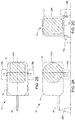
- FIGs. 2A, 2B, and 2C show a side, top, and rear view, respectively, of the exemplary round baler 10, in a simplified form for purposes of describing the bale weighing process of the present invention. Shown are the main frame 14, the tailgate 21, the tongue 18, the main support beam 15 on which the pair of wheels 16 (16a, 16b) are affixed, and a coupling point 220 at which the baler 10 is coupled to a tractor. A bale 200, formed by operation of the baler 10 as described above, is also shown in FIGs. 2A, 2B, and 2C .
- the bale weighing process is desirably performed on-site (e.g., the field on which the bale 200 is formed) when the baler 10 is stationary, features of the site are taken into account when determining the weight of the bale 200.
- the ground on which the baler 10 is positioned may not be level; the ground may be inclined an angle "a" with respect to a front-to-reverse direction of the baler 10 and an angle "b" with respect to a side-to-side direction of the baler 10.
- the measured weight of the baler 10 may not be accurate if the baler 10 is inclined longitudinally (front-to-reverse) or side-to-side.
- the size and shape of the bale 200 may affect the measured weight of the baler 10 obtained using a load cell. In particular, if the shape of the bale is not uniform, a reading on one or more load cells may not accurately represent the weight of the bale 200.
- a correction factor taking into account how the weight is changed based on either or both angle a and angle b and taking into account the size and/or shape of the bale 200 within the baler 10, is determined. This correction factor is then used to adjust a weight measurement of the bale 200, which is the difference between the measured weight of the baler 10 with the bale 200 and the weight of the baler 10 empty.
- two load sensors or cells 310 and 312 and two inclinometers 320 and 322 are incorporated into the baler 10 to determine the center of gravity of the baler 10 as well as that of bales 200 formed therein.
- the load cells 310, 312 measure the weight force exerted thereon;
- the inclinometer 320 measures the inclination of the baler 10 in a longitudinal direction (i.e., angle a, front-to-back of the baler 10); and the inclinometer 322 measures the inclination of the baler in the lateral direction (i.e., angle b, side-to-side).
- the load cells 310, 312 may be various types of load cells or sensors available in the field, such as, for example, those produced by Digi-Star that function to measure the weight force and interface the measured weight with one or more display and/or one or more processing units.
- the inclinometers may be various types of inclinometers available in the field that function to measure the slope or angle of inclination and interface with one or more display and/or one or more processing units.
- the load cells 310, 312 may be positioned at the wheel axles of the baler 10 at wheels 16a, 16b. Alternatively, one of the load cells 310, 312 may be positioned at the hitch or coupling point 220 of the baler 10.
- the inclinometers 320 and 322 may be positioned at any location on the baler, for example each may be positioned at the coupling point 220 of the baler 10.
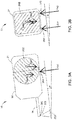
- FIGs. 3A and 3B show a side and rear view, respectively, of a first measurement configuration of the baler 10.
- the bale 200 is formed and contained within the baler 10, the baler 10 is stationary, and the tailgate 21 is closed.
- the load cells 310, 312 measure the weight force Fx1, Fx2 exerted thereon, with the total weight force being the sum of the two weight forces.
- the inclinometer 320 measures the angle a that the baler 10 is inclined in the longitudinal direction.
- the inclinometer 322 measures angle b in the lateral direction. The measurements may be obtained during a wrap cycle of the formed bale 200 or at another time when the bale 200 is formed.
- FIGs. 4A and 4B show a side and rear view, respectively, of a second measurement configuration of the baler 10.
- the bale 200 is removed from the baler 10, the baler 10 is stationary, and the tailgate 21 is closed or nearly closed (i.e., open a few degrees).
- the load cells 310, 312 measure the weight force Fz1, Fz2 exerted thereon, with the total weight force being the sum of the two weight forces.
- the inclinometer 320 measures the angle a that the baler 10 is inclined in the longitudinal direction.
- the inclinometer 322 measures angle b in the lateral direction.
- Fz1 and Fz2 are subtracted from values Fx1 and Fx2.
- This correction factor includes adjusting for the slope (angles a and b) and adjusting for the center of gravity of the bale in the baler.
- the size and/or the shape of the bale 200 may be used to determine a size/shape correction value to further adjust the weight of the bale 200.
- the center of the bale 200 moves rearward in relation to the baler frame 14. Consequently, when performing weight measurements with one or two load cells, it is important to know the center of gravity location of the bale.
- the center of gravity location of the bale 200 determines the weight distribution of the bale 200 on the support 220 and the wheels 16a and 16b. As the bale 200 grows in size, more of the bale weight is distributed at wheels 16a and 16b.
- a relationship may be determined to quantify the center of gravity location of the bale 200 versus the size of the bale 200 in a direction extending towards the front of the baler 10. This information is used to determine the percentage of the bale's weight on the axle of the baler at wheels 16a, 16b, which is used to determine a correction factor to be applied to the measured weight.
- the bale shape (e.g., cylindrical or conical) may also be actively measured on the baler 10 to adjust the end weight value of the bale 200.
- Sensors incorporated within the bale frame 14 may be used to determine the density of the bale 200 at different locations in the bale chamber (e.g., forward portion and end portion of the bale chamber), with the density serving as an indicator of the shape of the bale 200.
- bale weight F slope /B COG .
- a single load cell 610 may be incorporated into the baler 10 to determine the weight of bales formed therein.
- the load cell 610 may be positioned at either of the wheel axles of the baler 10 at wheels 16a, 16b.
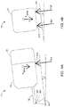
- FIGs. 5A and 5B show a side and rear view, respectively, of a first single load sensor measurement configuration of the baler 10.
- the bale 200 is formed and contained within the baler 10, the baler 10 is stationary, and the tailgate 21 is closed.
- the load cell 610 measures the weight force Fx exerted thereon. This may be done, for example, during the wrap cycle of the baler 10.
- FIGs. 6A and 6B show a side and rear view, respectively, of a second single load sensor measurement configuration of the baler 10.
- the bale 200 is removed from the baler 10
- the baler 10 is stationary, and the tailgate 21 is opened.
- the load cell 610 measures the weight force Fy exerted thereon.
- FIGs. 7A and 7B show a side and rear view, respectively, of a third single load sensor measurement configuration of the baler 10.
- the bale 200 is removed from the baler 10, the baler 10 is stationary, and the tailgate 21 is closed or nearly closed.
- the load cell 610 measures the weight force Fz exerted thereon.
- an inclinometer 620 measures the baler longitudinal orientation (angle a, front-to-back).
- the weight forces Fy and Fz can be used to determine the angle b with the use of basic trigonometric functions. This is possible as a known mass (tailgate 21) is being moved from one known tailgate position (open) to a second known tailgate position (closed).
- the bale weight can be determined in a similar manner as the first embodiment. Since only one load cell is used in this embodiment, an additional correction factor is needed based on side-to-side bale shape. This is needed as, for example, a bale that is not cylindrical, rather it is conical, may have more or less than 50 % of its weight on the load cell.
- This bale shape correction factor (B shape ) is determined by bale shape sensors on the bale.
- the weight of the baler 10 empty may be based on measurements when the tailgate 21 has moved to the open position and/or when the tailgate 21 has moved to the closed position. This requires that the baler remain stationary for some moments after the tailgate has closed to get an acceptable empty baler weight.
- the empty baler weight is based on measurements taken during the closing cycle of the tailgate 21, which provides uniform data as the tailgate 21 is moving through a controlled descent.
- a tailgate closed switch incorporated in and in communication with the tailgate 21 indicates when the tailgate 21 is closed.
- the empty baler weight is determined based on data obtained during a set amount of time prior to the tailgate switch closing. Since noise is generated in the data at essentially the same time the tailgate switch closes, the useable data may be in a range of approximately 2 seconds to 0.5 seconds prior to the tailgate closing, for example. Other ranges of data may also be used.
- FIG. 8 illustrates a flowchart of a method of weighing a round bale 200 utilizing the two load sensors or cells 310 and 312 and the inclinometers 320 and 322 as described above with reference to the measurement configurations of FIGs. 3A-4B .
- a weight measurement Fx1, Fx2 of the baler 10 is obtained at the two load cells 310 and 312 and angle measurements a and b of the forward-to-reverse incline and side-to-side incline of the baler 10 are obtained with the inclinometers 320 and 322 (see FIGs. 3A and 3B ).
- a second measurement is obtained with the two load cells 310 and 312 and the inclinometers 320 and 322 (see FIGs. 4A and 4B ).
- the second measurement includes the weight Fz1, Fz2 of the baler 10 and the angles a and b of the forward-to-reverse and side-to-side incline of the baler 10.
- the empty baler weight is based on measurements taken during the closing cycle of the tailgate 21.
- a correction factor is determined.
- the correction factor is a function of the forward-to-reverse and side-to-side incline angles a and b of the baler 10, as well as a percentage of the bale weight determined to be on the load cells 310 and 312. This factor is based on bale size and baler orientation.
- a weight of the bale 200 is determined by adjusting the weight measurement Fx1, Fx2 of the baler.
- the correction factor is used to adjust the weight measurement.
- an indication of the weight of the bale 200 may be displayed to an operator of the baler 10 via a monitor in the cab of the baler 10, for example.
- the bale 200 may be removed and the close cycle of the tailgate 21 may begin.
- the load cells 310 and 312 and/or the inclinometers 320 and 322 may provide an indication (i.e., signal) to a processing device that the measurement is complete, thereby indicating that the tailgate 21 should open and that the formed bale 200 should be ejected, the operation of which may be controlled by a processing device.
- the baler 10 may wait a predetermined amount of time before moving to the second measurement configuration after the bale 200 is formed and/or wrapped.
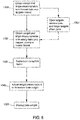
- FIG. 9 illustrates a flowchart of an exemplary method of weighing a round bale 200 utilizing the load sensor or cell 610 and the inclinometer 620 as described above with reference to the measurement configurations of FIGs. 5A-7B .
- a weight measurement Fx of the baler 10 is obtained at the single load cell 610, as is the forward to reverse baler angle a with the inclinometer 620 (see FIGs. 5A and 5B ).
- a first test measurement is obtained with the load cell 610 (see FIGs. 6A and 6B ).
- the first test measurement includes the weight Fy of the baler 10.
- angle b (the side-to-side incline of the baler 10) is determined as a function of the first and second test measurements, Fy and Fz, respectively, of the weight of the baler 10.
- the known weight of the empty baler 10 is subtracted from Fx to obtain the weight of the bale 200 on the load cell.
- the known weight of the empty baler 10 corresponds to Fz.
- Angles a and b are used to adjust the weight measurement of the bale 200, thereby taking into account effects that angles a and b have on the weight measurement.
- the center of gravity location of the bale 200 and the bale shape are applied to further adjust the bale weight measurement.
- an indication of the weight of the bale 200 may be displayed to an operator of the baler 10 via a monitor in the cab of the baler 10, for example.
- the load cell 610 and/or inclinometer 620 may provide an indication (i.e., signal) to a processing device that the measurements are complete, thereby indicating that the tailgate 21 should be opened and the formed bale 200 should be ejected, the operation of which may be controlled by a processing device. Alternately, a predetermined amount of time may pass before the opening of the tailgate 21 and the ejection of the bale 200.
- the tailgate 21 is moved to a closed position.
- the load cell 610 and/or inclinometer 620 may provide an indication (i.e., signal) to a processing device that the measurement is complete, thereby indicating that the tailgate 21 should begin closing, the operation of which may be controlled by a processing device.
- a predetermined amount of time may pass after the bale 200 is ejected from the baler 10 before the tailgate 21 begins closing.
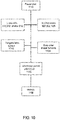
- FIG. 10 is a block diagram of components, for weighing a bale 200, the two-sensor example in which is not in accordance with the invention as claimed.
- a power unit 1110 may provide power to one or more of the other components, including the load cells 310, 312, and 610; the inclinometers 320, 322, and 620; an electronic control unit (ECU) 1120; a monitor 1130; a tailgate latch sensor 1140; and bale shape/size sensors 1150.
- ECU electronice control unit
- the ECU 1120 may be a processing device, computing device, processor, or the like for performing calculations and operations described herein.
- the ECU 1120 may perform calculations related to the correction factor, angles a and b, and the weight of the bale 200.
- the ECU 1120 may also operate to move the tailgate 21 to the various positions for obtaining the measurements Fx1, Fx2, Fz1, and Fz2; Fx, Fy, and Fz; and the forward-to-reverse angle a and side-to-side angle b of the baler 10.
- the ECU 1120 interfaces with the load cells 310, 312, and 610; the inclinometers 320, 322, and 620; the monitor 1130; the tailgate latch sensor 1140; the bale shape/size sensors 1150; and the power unit 1110.
- the ECU 1120 may also interface with one or more memory devices (not shown) such as read only memory (ROM), random access memory (RAM), and one or more optional non-transitory memory devices such as, for example, an external or internal DVD drive, a CD ROM drive, a hard drive, flash memory, a USB drive, or the like.
- the memory devices may be configured to include individual files and/or one or more databases for storing any software modules, instructions, or data.
- the memory devices may store pre-determined information and date related to the correction factors, for example.
- Program instructions, software, or interactive modules for performing any of the functional steps associated with the processes as described above may be stored in the ROM and/or the RAM.
- the program instructions may be stored on a tangible computer readable medium such as a compact disk, a digital disk, flash memory, a memory card, a USB drive, an optical disc storage medium, such as a Blu-rayTM disc, and/or other recording medium.
- a display interface may permit information from the ECU 1120 to be displayed on the monitor 1130 in audio, visual, graphic, and/or alphanumeric format.
- the monitor 1130 may be positioned in a cab utilized by the operator of the baling process so that the operator may safely and conveniently see the information during and after operation, such as the weight measurements of the bale 200.
- Communication with external devices may occur using various communication ports that may be attached to one or more communications networks, such as the Internet or a local area network, or directly to a portable computing device such as a notebook computer.
- An interface may allow for receipt of data from input devices such as a keyboard, a mouse, a joystick, a touch screen, a remote control, a pointing device, a video input device, an audio input device, and the like accessible by the operator.
Landscapes
- Life Sciences & Earth Sciences (AREA)
- Environmental Sciences (AREA)
- Physics & Mathematics (AREA)
- General Physics & Mathematics (AREA)
- Harvester Elements (AREA)
- Preliminary Treatment Of Fibers (AREA)
Description
- The present invention relates generally to weighing round bales, and more particularly to a weighing system incorporated within a round baler for the weighing of a bale formed therein.
- For many years agricultural balers have been used to consolidate and package crop material to facilitate the storage and handling of the crop material for later use. Usually, a mower-conditioner cuts and conditions the crop material for windrow drying in the sun. When the cut crop material is properly dried, a baler, for example a round baler, travels along the windrows to pick up the crop material and form it into cylindrically-shaped round bales.
- More specifically, pickups of the baler gather the cut and windrowed crop material from the ground, then convey the cut crop material into a bale-forming chamber within the baler. A drive mechanism operates to activate the pickups, augers, and a rotor of the feed mechanism. A conventional baling chamber may include a pair of opposing sidewalls with a series of belts that rotate and compress the crop material into a cylindrical shape.
- When the bale has reached a desired size and density, a wrapping system may wrap the bale to ensure that the bale maintains its shape and density. For example, a net may be used to wrap the bale of crop material. A cutting or severing mechanism may be used to cut the net once the bale has been wrapped. The wrapped bale may be ejected from the baler and onto the ground by, for example, raising a tailgate of the baler. The tailgate is then closed and the cycle repeated as necessary and desired to manage the field of cut crop material.
-
EP 2 446 731 describes a method for determining the weight of a baler, which also compensates for un-level terrains such as hillsides. Therefore, the empty baler tare weight is measured while the baler is on a level surface. During operation, the weight of the baler and the formed bale is measured and the raw bale weight is calculated by deducting the empty baler tare weight from the full baler weight. To overcome an error due to un-level terrains, a further measurement is done when the baler has ejected the formed bale. By using the weight result of this empty baler in the field and the measured empty baler tare weight, a correction factor can be calculated which is used to calculate the weight of the bale while taken the uneven terrain into consideration.
The downside of this method is that the empty baler tare weight is used to calculate the weight of the bale. This measurement is done prior to the actual baling and the weight of the machine can change due to the adding of new wrapping rolls or by using these rolls throughout the day. This will change the tare weight of the baler and will have an effect on the calculation of the weight of the formed bale resulting in the introduction of an error when baling. -
US 6,378,276 discloses a baler having a compression chamber housing, a support axle, springs provided on both sides of the compression chamber housing for supporting the housing on the support axle with a possibility of vertical displacement relative to the support axle, and sensors for determining a distance between the compression chamber housing and the support axle. Signals are generated representing this distance and these signals in turn correspond to the bale weight. Also in this embodiment, the empty weight of the baler is set as a nil value of the weighing device. If the weight changes during baling because e.g. the wrapping material is being used, the empty weight which is set as the nil value is no longer correct and a wrong weight will be calculated. - A weighing system incorporated in the baler that provides weight measurements of the formed bale is desired. Such a system is desirable to eliminate use of a separate scale, while also providing weight measurements to the operator of the baler and customers soon after completion of forming the bale.
- This document describes an apparatus and processes for weighing round bales.
- Embodiments of the present invention provide methods for weighing a bale formed by a round baler, and a round baler with a processing unit coupled to one or more load sensors and one or more inclinometers for determining a weight of a bale.
- In one embodiment, a method of weighing a bale formed by a round baler having a main support beam on which a pair of wheels are rotatably affixed and a coupling point for coupling the round baler to a tractor, the wheels and the coupling point constituting supporting points of the baler, includes: obtaining one or more bale weight measurements, with a load sensor, of the baler with a formed bale contained therein, the load sensor being positioned at a supporting point of the round baler without using load sensors at each supporting point of the baler; obtaining two or more empty baler weight measurements, with the load sensor, of the baler empty; and determining, by a processing unit in communication with the load sensor, a corrected bale weight by adjusting a first bale weight, the first bale weight being a function of the one or more bale weight measurements and the two or more empty baler weight measurements; wherein the first bale weight is adjusted based upon one or more of (i) one or more slopes on a surface on which the baler is positioned, wherein the one or more slopes comprises one or more of a front-to-back angle and a side-to-side angle of the baler; (ii) a size of the bale; and (iii) a shape of the bale, characterised in that the load sensor comprises a single load sensor positioned at one of a first wheel axle or a second wheel axle of the baler, and in that the method further comprises: obtaining the front-to-back angle with an inclinometer in communication with the processing unit; and obtaining the side-to-side angle based upon the empty baler weight measurements in which a tailgate of the baler is in two known positions.
- According to an embodiment, a round baler is comprised of: a main frame with a main support beam on which a pair of wheels are rotatably affixed, each wheel comprising a wheel axle, the main frame including a bale forming chamber in which a bale is formed; a tailgate pivotally connected to the main frame, the tailgate configured to pivot open to discharge a formed bale; a coupling point for coupling the round baler to a tractor, the coupling point and the pair of wheels being the supporting points of the round baler; a load sensor positioned at a respective wheel axle, for measuring a weight force exerted thereon, wherein the load sensor obtains the following measurements: (i) one or more bale weight measurements of the baler with a formed bale contained therein; and (ii) two or more empty baler weight measurements of the baler after removal of the bale; wherein the round baler further comprises: an inclinometer positioned at the coupling point for obtaining a front-to-back angle of the baler; and a processing unit coupled to the load sensor, the processing unit configured to calculate a weight of the bale by determining a corrected bale weight by adjusting a first bale weight, the first bale weight being a function of the one or more bale weight measurements, the one or more empty baler weight measurements and the front-to-back angle and/or a side-to-side angle of the baler, wherein the first bale weight is adjusted based upon one or more of: (i) one or more slopes on a surface on which the baler is positioned, wherein the one or more slopes comprises one or more of the front-to-back angle and the side-to-side angle of the baler; (ii) a size of the bale; and (iii) a shape of the bale, characterised in that the load sensor comprises a single load sensor positioned at one of a first wheel axle or a second wheel axle of the baler, wherein the inclinometer is in communication with the processing unit; and wherein a side-to-side angle is determined based upon the empty baler weight measurements in which the tailgate of the baler is in two known positions.
- According to an embodiment, the one or more bale weight measurements are obtained during a wrap cycle of the formed bale.
- According to an embodiment, the one or more empty baler weight measurements are obtained during a tailgate close cycle.
- According to various aspects, the corrected bale weight is determined by adjusting the first bale weight based upon the front-to-back angle and the side-to-side angle of the baler and the size of the bale; and wherein the size of the bale is a function of a center of gravity location of the bale.
- The corrected bale weight is determined by adjusting the first bale weight based upon the front-to-back angle and the side-to-side angle of the baler, the size of the bale, and the shape of the bale; wherein the size of the bale is a function of a center of gravity location of the bale; and wherein the shape of the bale is a function of the density of the bale at more than one bale shape sensor positioned in the baler.
- According to an embodiment, a display interface connected to the processing unit is configured to display on a monitor an indication of the corrected bale weight.
- In an embodiment, a tailgate latch sensor in communication with the tailgate is configured to indicate when the tailgate is closed. In this embodiment, the one or more empty baler weight measurements are obtained during a tailgate close cycle.
- The foregoing and other aspects of the present invention are best understood from the following detailed description when read in connection with the accompanying drawings. For the purpose of illustrating the invention, there is shown in the drawings embodiments that are presently preferred, it being understood, however, that the invention is not limited to the specific instrumentalities disclosed. Included in the drawings are the following Figures:
-
FIG. 1 is a cutaway side elevational view of an exemplary round baler in which the present invention may be employed; -
FIGs. 2A, 2B, and 2C show a side, top, and rear view, respectively, of an exemplary round baler; -
FIGs. 3A-7B show side and rear views of measurement configurations of the exemplary round baler, according to embodiments, with the configurations ofFigures 3 and4 not forming part of the invention as claimed; -
FIG. 8 illustrates a flowchart of an exemplary method of weighing a round bale not forming part of the invention as claimed; -
FIG. 9 illustrates a flowchart of an exemplary method of weighing a round bale as claimed herein; and -
FIG. 10 is a block diagram of components utilized for weighing a round bale. - Embodiments of the present invention relate to weighing a round bale formed by a round baler. In addition to utilizing one or more load cells or sensors to obtain a measurement of the baler containing the bale, factors related to adjusting the weight based on angles of inclination of the baler and the size, shape, and location of the bale are taken into account to achieve an accurate bale weight determination.
- Agricultural balers, such as round balers, are well known in the agricultural industry, and the instant invention can be used with substantially any of such machines. Reference is made, for example, to
U.S. Patent Nos. 6,877,304 ;6,688,092 ;6,644,006 ; and6,295,797 that illustrate such balers. For illustrative purposes, details of an exemplary round baler in which the features of the present invention may be used are disclosed in and will be described here in part with reference toU.S. Patent No. 5,581,976 . -
FIG. 1 depicts an exemplary agricultural round baler, generally designated 10, in which embodiments of the present invention may be employed. As previously noted, crop in the field is usually arranged in a windrow as it is engaged by thebaler 10 being pulled along the windrow of cut crop material by a tractor (not shown). -
FIG. 1 shows a fixedchamber round baler 10 having a wrapping system for wrapping a cylindrical package of crop material (not shown) formed in around baler 10. More particularly, the wrapping system ofbaler 10 comprises anet dispensing assembly 11 and acutting assembly 12 for cutting web material, such as net, issued from asupply roll 13. As shown,round baler 10 includes amain frame 14 with amain support beam 15 on which a pair of wheels 16 (only one shown) are rotatably affixed. The main frame includes a pair of side walls between which a cylindrical bale forming chamber extends. For the purposes of clarity only onewall 17 is shown inFIG. 1 and the elements mounted inwardly thereof are shown in full lines for clarity, which is an approach not uncommon in the descriptions in patents. For illustrative purposes reference letter B is used to designate a bale, shown in cross section in the chamber. -
Baler 10 also includes atongue 18 extending from the forward portion ofmain frame 14 for conventional connection to a tractor (not shown). Pivotally connected to the sidewalls ofmain frame 14 by a pair of stub shafts 20 istailgate 21 which may be closed (as shown inFIG. 1 ) during bale formation or pivoted open about stub shafts 20 to discharge a completed bale. The tailgate includestailgate walls 22 coextensive withside walls 17. Apickup assembly 23 mounted onmain frame 14 in a suitable manner includes a plurality of fingers ortines 24 moveable in a predetermined path to lift crop material from the ground, generally depicted by direction arrow C, and deliver it rearwardly (arrow D) toward atransverse inlet 25 in the chamber defined by afloor roll 26 and atransverse stripper roll 27, both of which rolls are rotatably supported onmainframe 14 betweensidewalls 17. - As shown, the bale forming chamber is defined primarily by an
apron assembly 28 comprising a pair of support chains 30 mounted to travel along a continuous path, the inner run of which is defined onsidewalls 17 andtailgate walls 22 by front andrear sections 31, 32 of a continuous chain guide track that separates at a point of track adjacent the stub shaft 20 during bale discharge. The apron further comprises a plurality of parallel tubularcrop engaging slats 33 extending between chains 30 to provide a cage-like periphery of the cylindrically shaped chamber. Radially outward of the inner run ofapron assembly 28 are front andrear sections side walls 17 andtailgate walls 22, respectively, for maintaining integrity between the outer and inner runs of chain 30. Operatively engaged with chain 30 are drive sprocket 36 mounted betweensidewalls 17,idler sprockets 37 also mounted betweensidewalls 17 on shaft 20, andidler sprocket 38 mounted betweentailgate walls 22. A conventional chain drive system for drive sprocket 36 is provided via appropriate coupling togearbox 40 in a conventional manner, diagrammatically depicted in phantom outline outwardly ofsidewall 17. The bale forming chamber is further defined by the outer conveying surfaces offloor roll 26 andstripper roll 27, both of which are driven in a direction opposite that of the bale chamber direction by conventional drive means appropriately coupled togear box 40. InFIG. 1 ,floor roll 26 receives bale material at its forward surface, moving the bale material upward and rearward, clockwise as shown inFIG. 1 . Bale material leaves thefloor roll 26 and enters the bale chamber which rotates moving the bale material from a lower position, rearward and upward in a circular motion, counterclockwise as shown inFIG. 1 . These rolls 26, 27 may be provided withribs 41, 42 to enhance their ability to convey crops in the chamber as a bale is being formed. Other forms of aggressive surface structure may be used to accommodate various types of crops and conditions. -
FIGs. 2A, 2B, and 2C show a side, top, and rear view, respectively, of theexemplary round baler 10, in a simplified form for purposes of describing the bale weighing process of the present invention. Shown are themain frame 14, thetailgate 21, thetongue 18, themain support beam 15 on which the pair of wheels 16 (16a, 16b) are affixed, and acoupling point 220 at which thebaler 10 is coupled to a tractor. Abale 200, formed by operation of thebaler 10 as described above, is also shown inFIGs. 2A, 2B, and 2C . - It is desired by operators to accurately determine the weight of the
bale 200 without moving thebale 200 to a special location for performing such a measurement. It is also desirable to obtain weight measurements without using load sensors at each supporting point of the baler 10 (i.e., each wheel and the hitch). Thus, various features relating to thebale 200 and/or to thebaler 10 are taken into account to determine a correction factor to apply to weight measurements taken of thebaler 10 with thebale 200 contained therein. - Since the bale weighing process is desirably performed on-site (e.g., the field on which the
bale 200 is formed) when thebaler 10 is stationary, features of the site are taken into account when determining the weight of thebale 200. In particular, the ground on which thebaler 10 is positioned may not be level; the ground may be inclined an angle "a" with respect to a front-to-reverse direction of thebaler 10 and an angle "b" with respect to a side-to-side direction of thebaler 10. If the weight of thebaler 10 is measured with one or more load cells (but not including a load cell at each support point of the baler 10), for example, the measured weight of thebaler 10 may not be accurate if thebaler 10 is inclined longitudinally (front-to-reverse) or side-to-side. Moreover, according to further embodiments, the size and shape of thebale 200 may affect the measured weight of thebaler 10 obtained using a load cell. In particular, if the shape of the bale is not uniform, a reading on one or more load cells may not accurately represent the weight of thebale 200. Thus, to accurately determine the weight of abale 200 contained within thebaler 10, a weight measurement with a load cell cannot simply be taken; instead, the effect of the angle a and/or angle b, as well as the size and shape of thebale 200, have to be taken into account. - According to embodiments, a correction factor, taking into account how the weight is changed based on either or both angle a and angle b and taking into account the size and/or shape of the
bale 200 within thebaler 10, is determined. This correction factor is then used to adjust a weight measurement of thebale 200, which is the difference between the measured weight of thebaler 10 with thebale 200 and the weight of thebaler 10 empty. - With reference to
FIGs. 3A through 4 , which show arrangements not in accordance with the invention as claimed, two load sensors orcells inclinometers baler 10 to determine the center of gravity of thebaler 10 as well as that ofbales 200 formed therein. Theload cells inclinometer 320 measures the inclination of thebaler 10 in a longitudinal direction (i.e., angle a, front-to-back of the baler 10); and theinclinometer 322 measures the inclination of the baler in the lateral direction (i.e., angle b, side-to-side). Theload cells load cells baler 10 atwheels load cells coupling point 220 of thebaler 10. Theinclinometers coupling point 220 of thebaler 10. -
FIGs. 3A and 3B show a side and rear view, respectively, of a first measurement configuration of thebaler 10. In the first measurement configuration, thebale 200 is formed and contained within thebaler 10, thebaler 10 is stationary, and thetailgate 21 is closed. Theload cells inclinometer 320 measures the angle a that thebaler 10 is inclined in the longitudinal direction. Theinclinometer 322 measures angle b in the lateral direction. The measurements may be obtained during a wrap cycle of the formedbale 200 or at another time when thebale 200 is formed. -
FIGs. 4A and 4B show a side and rear view, respectively, of a second measurement configuration of thebaler 10. In the second measurement configuration, thebale 200 is removed from thebaler 10, thebaler 10 is stationary, and thetailgate 21 is closed or nearly closed (i.e., open a few degrees). Theload cells inclinometer 320 measures the angle a that thebaler 10 is inclined in the longitudinal direction. Theinclinometer 322 measures angle b in the lateral direction. - In order to determine the load cell reaction due to the
bale 200, Fz1 and Fz2 are subtracted from values Fx1 and Fx2. The resultant values equals the load cell reaction due to the bale:
- In order to determine the actual bale weight, a correction factor needs to be applied. This correction factor includes adjusting for the slope (angles a and b) and adjusting for the center of gravity of the bale in the baler. The slope correction factor uses simple trigonometric functions to determine the actual reaction load reaction. For instance:

- In addition to using the
load cells inclinometers bale 200, the size and/or the shape of thebale 200 may be used to determine a size/shape correction value to further adjust the weight of thebale 200. As thebale 200 grows, the center of thebale 200 moves rearward in relation to thebaler frame 14. Consequently, when performing weight measurements with one or two load cells, it is important to know the center of gravity location of the bale. The center of gravity location of thebale 200 determines the weight distribution of thebale 200 on thesupport 220 and thewheels bale 200 grows in size, more of the bale weight is distributed atwheels bale 200 versus the size of thebale 200 in a direction extending towards the front of thebaler 10. This information is used to determine the percentage of the bale's weight on the axle of the baler atwheels - Similarly, the bale shape (e.g., cylindrical or conical) may also be actively measured on the
baler 10 to adjust the end weight value of thebale 200. Sensors incorporated within thebale frame 14 may be used to determine the density of thebale 200 at different locations in the bale chamber (e.g., forward portion and end portion of the bale chamber), with the density serving as an indicator of the shape of thebale 200. - The actual bale weight is then determined by adjusting Fslope by the bale center of gravity location factor BCOG. This factor determines the percent weight of the bale on the load cells based on diameter and slope, so that:

- According to an embodiment of the invention, and as an alternate solution to utilizing the correction factor as described above, a
single load cell 610 may be incorporated into thebaler 10 to determine the weight of bales formed therein. Theload cell 610 may be positioned at either of the wheel axles of thebaler 10 atwheels -
FIGs. 5A and 5B show a side and rear view, respectively, of a first single load sensor measurement configuration of thebaler 10. In this configuration, thebale 200 is formed and contained within thebaler 10, thebaler 10 is stationary, and thetailgate 21 is closed. Theload cell 610 measures the weight force Fx exerted thereon. This may be done, for example, during the wrap cycle of thebaler 10. -
FIGs. 6A and 6B show a side and rear view, respectively, of a second single load sensor measurement configuration of thebaler 10. In this configuration, thebale 200 is removed from thebaler 10, thebaler 10 is stationary, and thetailgate 21 is opened. Theload cell 610 measures the weight force Fy exerted thereon. -
FIGs. 7A and 7B show a side and rear view, respectively, of a third single load sensor measurement configuration of thebaler 10. In this measurement configuration, thebale 200 is removed from thebaler 10, thebaler 10 is stationary, and thetailgate 21 is closed or nearly closed. Theload cell 610 measures the weight force Fz exerted thereon. For all 3 measurement configurations, an inclinometer 620 measures the baler longitudinal orientation (angle a, front-to-back). - The weight forces Fy and Fz can be used to determine the angle b with the use of basic trigonometric functions. This is possible as a known mass (tailgate 21) is being moved from one known tailgate position (open) to a second known tailgate position (closed). Once angle b is determined, the bale weight can be determined in a similar manner as the first embodiment. Since only one load cell is used in this embodiment, an additional correction factor is needed based on side-to-side bale shape. This is needed as, for example, a bale that is not cylindrical, rather it is conical, may have more or less than 50 % of its weight on the load cell. This bale shape correction factor (Bshape) is determined by bale shape sensors on the bale. The resultant bale weight calculations are:


- In the example measurement configurations described above, the weight of the
baler 10 empty may be based on measurements when thetailgate 21 has moved to the open position and/or when thetailgate 21 has moved to the closed position. This requires that the baler remain stationary for some moments after the tailgate has closed to get an acceptable empty baler weight. In another embodiment, the empty baler weight is based on measurements taken during the closing cycle of thetailgate 21, which provides uniform data as thetailgate 21 is moving through a controlled descent. A tailgate closed switch incorporated in and in communication with thetailgate 21 indicates when thetailgate 21 is closed. According to this embodiment, the empty baler weight is determined based on data obtained during a set amount of time prior to the tailgate switch closing. Since noise is generated in the data at essentially the same time the tailgate switch closes, the useable data may be in a range of approximately 2 seconds to 0.5 seconds prior to the tailgate closing, for example. Other ranges of data may also be used. -
FIG. 8 illustrates a flowchart of a method of weighing around bale 200 utilizing the two load sensors orcells inclinometers FIGs. 3A-4B . - At 1310, at a first measurement configuration of the
baler 10 in which thebale 200 is formed and thetailgate 21 of thebaler 10 is closed, a weight measurement Fx1, Fx2 of thebaler 10 is obtained at the twoload cells baler 10 are obtained with theinclinometers 320 and 322 (seeFIGs. 3A and 3B ). - At 1320, when the
baler 10 is in a second measurement configuration in which thebale 200 is removed from thebaler 10 and thetailgate 21 is closed or nearly closed, a second measurement is obtained with the twoload cells inclinometers 320 and 322 (seeFIGs. 4A and 4B ). The second measurement includes the weight Fz1, Fz2 of thebaler 10 and the angles a and b of the forward-to-reverse and side-to-side incline of thebaler 10. The empty baler weight is based on measurements taken during the closing cycle of thetailgate 21. - At 1330, a correction factor is determined. The correction factor is a function of the forward-to-reverse and side-to-side incline angles a and b of the
baler 10, as well as a percentage of the bale weight determined to be on theload cells - At 1340, a weight of the
bale 200 is determined by adjusting the weight measurement Fx1, Fx2 of the baler. The correction factor is used to adjust the weight measurement. - At 1350, an indication of the weight of the
bale 200 may be displayed to an operator of thebaler 10 via a monitor in the cab of thebaler 10, for example. - At 1360, following 1310, after the weight measurement Fx1, Fx2 is taken, the
bale 200 may be removed and the close cycle of thetailgate 21 may begin. Theload cells inclinometers tailgate 21 should open and that the formedbale 200 should be ejected, the operation of which may be controlled by a processing device. Alternately, thebaler 10 may wait a predetermined amount of time before moving to the second measurement configuration after thebale 200 is formed and/or wrapped. -
FIG. 9 illustrates a flowchart of an exemplary method of weighing around bale 200 utilizing the load sensor orcell 610 and the inclinometer 620 as described above with reference to the measurement configurations ofFIGs. 5A-7B . - At 1410, when the
bale 200 is formed and thetailgate 21 of thebaler 10 is closed, a weight measurement Fx of thebaler 10 is obtained at thesingle load cell 610, as is the forward to reverse baler angle a with the inclinometer 620 (seeFIGs. 5A and 5B ). - At 1420, when the
bale 200 is removed from thebaler 10 and thetailgate 21 is opened, a first test measurement is obtained with the load cell 610 (seeFIGs. 6A and 6B ). The first test measurement includes the weight Fy of thebaler 10. - At 1430, when the
bale 200 is removed from thebaler 10 and thetailgate 21 is closed or nearly closed, a second test measurement is obtained with theload cell 610 to obtain the weight Fz of the baler 10 (seeFIGs. 7A and 7B ). - At 1440, angle b (the side-to-side incline of the baler 10) is determined as a function of the first and second test measurements, Fy and Fz, respectively, of the weight of the
baler 10. - At 1450, the known weight of the
empty baler 10 is subtracted from Fx to obtain the weight of thebale 200 on the load cell. The known weight of theempty baler 10 corresponds to Fz. Angles a and b are used to adjust the weight measurement of thebale 200, thereby taking into account effects that angles a and b have on the weight measurement. The center of gravity location of thebale 200 and the bale shape are applied to further adjust the bale weight measurement. - At 1460, an indication of the weight of the
bale 200 may be displayed to an operator of thebaler 10 via a monitor in the cab of thebaler 10, for example. - At 1470, following 1410, after the weight measurement Fx is taken, the
load cell 610 and/or inclinometer 620 may provide an indication (i.e., signal) to a processing device that the measurements are complete, thereby indicating that thetailgate 21 should be opened and the formedbale 200 should be ejected, the operation of which may be controlled by a processing device. Alternately, a predetermined amount of time may pass before the opening of thetailgate 21 and the ejection of thebale 200. - At 1480, following 1420, after the weight measurement Fy is taken, the
tailgate 21 is moved to a closed position. Theload cell 610 and/or inclinometer 620 may provide an indication (i.e., signal) to a processing device that the measurement is complete, thereby indicating that thetailgate 21 should begin closing, the operation of which may be controlled by a processing device. Alternately, a predetermined amount of time may pass after thebale 200 is ejected from thebaler 10 before thetailgate 21 begins closing. -
FIG. 10 is a block diagram of components, for weighing abale 200, the two-sensor example in which is not in accordance with the invention as claimed. Apower unit 1110 may provide power to one or more of the other components, including theload cells inclinometers monitor 1130; a tailgate latch sensor 1140; and bale shape/size sensors 1150. - The
ECU 1120 may be a processing device, computing device, processor, or the like for performing calculations and operations described herein. TheECU 1120 may perform calculations related to the correction factor, angles a and b, and the weight of thebale 200. TheECU 1120 may also operate to move thetailgate 21 to the various positions for obtaining the measurements Fx1, Fx2, Fz1, and Fz2; Fx, Fy, and Fz; and the forward-to-reverse angle a and side-to-side angle b of thebaler 10. - The
ECU 1120 interfaces with theload cells inclinometers monitor 1130; the tailgate latch sensor 1140; the bale shape/size sensors 1150; and thepower unit 1110. TheECU 1120 may also interface with one or more memory devices (not shown) such as read only memory (ROM), random access memory (RAM), and one or more optional non-transitory memory devices such as, for example, an external or internal DVD drive, a CD ROM drive, a hard drive, flash memory, a USB drive, or the like. The memory devices may be configured to include individual files and/or one or more databases for storing any software modules, instructions, or data. The memory devices may store pre-determined information and date related to the correction factors, for example. - Program instructions, software, or interactive modules for performing any of the functional steps associated with the processes as described above may be stored in the ROM and/or the RAM. Optionally, the program instructions may be stored on a tangible computer readable medium such as a compact disk, a digital disk, flash memory, a memory card, a USB drive, an optical disc storage medium, such as a Blu-ray™ disc, and/or other recording medium.
- A display interface may permit information from the
ECU 1120 to be displayed on themonitor 1130 in audio, visual, graphic, and/or alphanumeric format. For example, themonitor 1130 may be positioned in a cab utilized by the operator of the baling process so that the operator may safely and conveniently see the information during and after operation, such as the weight measurements of thebale 200. Communication with external devices may occur using various communication ports that may be attached to one or more communications networks, such as the Internet or a local area network, or directly to a portable computing device such as a notebook computer. An interface may allow for receipt of data from input devices such as a keyboard, a mouse, a joystick, a touch screen, a remote control, a pointing device, a video input device, an audio input device, and the like accessible by the operator.
Claims (11)
- A method of weighing a bale (200) formed by a round baler (10) having a main support beam on which a pair of wheels (16) are rotatably affixed and a coupling point (220) for coupling the round baler (10) to a tractor, the wheels and the coupling point constituting supporting points (16a, 16b, 220) of the baler (10) and the method comprising:- obtaining one or more bale weight measurements (Fx1,Fx2;Fx), with a load sensor (610), of the baler with a formed bale contained therein, the load sensor (610) being positioned at a supporting point (16a,16b,220) of the round baler (10) without using load sensors at each supporting point (16a, 16b, 220) of the baler (10);- obtaining two or more empty baler weight measurements (Fz1,Fz2;Fy,Fz) with the load sensor (610), of the baler empty; and- determining, by a processing unit (1120) in communication with the load sensor (610), a corrected bale weight by adjusting a first bale weight, the first bale weight being a function of the one or more bale weight measurements (Fx1,Fx2; Fx) and the two or more empty baler weight measurements (Fz1,Fz2; Fz);wherein the first bale weight is adjusted based upon one or more of(i) one or more slopes (a, b) on a surface on which the baler is positioned, wherein the one or more slopes comprises one or more of a front-to-back angle (a) and a side-to-side angle (b) of the baler (10);(ii) a size of the bale; and(iii) a shape of the bale, characterised in that the load sensor comprises a single load sensor (610) positioned at one of a first wheel axle or a second wheel axle of the baler, and in that the method further comprises: obtaining the front-to-back angle (a) with an inclinometer (620) in communication with the processing unit (1120); and obtaining the side-to-side angle (b) based upon the empty baler weight measurements in which a tailgate (21) of the baler (10) is in two known positions.
- The method of claim 1, wherein the one or more bale weight measurements are obtained during a wrap cycle of the formed bale.
- The method of claim 1 or claim 2, wherein the two or more empty baler weight measurements are obtained during a tailgate close cycle.
- The method of any of the claims 1 to 3, wherein the corrected bale weight is determined by adjusting the first bale weight based upon the front-to-back angle (a) and the side-to-side angle (b) of the baler (10) and the size of the bale (200); and wherein the size of the bale is a function of a center of gravity location of the bale.
- The method of claim 1, wherein the corrected bale weight is determined by adjusting the first bale weight based upon the front-to-back angle (a) and the side-to-side angle (b) of the baler (10), the size of the bale (200), and the shape of the bale (200); wherein the size of the bale is a function of a center of gravity location of the bale; and wherein the shape of the bale is a function of the density of the bale at more than one bale shape sensor (1150) positioned in the baler (10).
- The method of any one of the previous claims, further comprising:
displaying on a monitor (1130), via a display interface connected to the processing unit (1120), an indication of the corrected bale weight. - A round baler (10) comprising:- a main frame (14) with a main support beam (15) on which a pair of wheels (16a,16b) are rotatably affixed, each wheel comprising a wheel axle, the main frame including a bale forming chamber in which a bale (B, 200) is formed;- a tailgate (21) pivotally connected to the main frame, the tailgate configured to pivot open to discharge a formed bale;- a coupling point (220) for coupling the round baler (10) to a tractor, the coupling point (220) and the pair of wheels (16a,16b) being the supporting points of the round baler (10);- a load sensor (610) positioned at a respective wheel axle, for measuring a weight force exerted thereon, wherein the load sensor obtains the following measurements:wherein the round baler (10) further comprises(i) one or more bale weight measurements (Fx1,Fx2;Fx) of the baler (10) with a formed bale (200) contained therein; and(ii) two or more empty baler weight measurements (Fz1, Fz2;Fy,Fz) of the baler after removal of the bale;- an inclinometer (620) positioned at the coupling point (220) for obtaining a front-to-back angle (a) of the baler (10); and- a processing unit (1120) coupled to the load sensor, the processing unit configured to calculate a weight of the bale by determining a corrected bale weight by adjusting a first bale weight, the first bale weight being a function of the one or more bale weight measurements (Fx1,Fx2;Fx), the two or more empty baler weight measurements (Fz1,Fz2;Fy,Fz) and the front-to-back angle (a) and/or a side-to-side angle (b) of the baler (10), wherein the first bale weight is adjusted based upon one or more of:(i) one or more slopes (a, b) on a surface on which the baler is positioned, wherein the one or more slopes comprises one or more of the front-to-back angle (a) and the side-to-side angle (b) of the baler (10);(ii) a size of the bale; and(iii) a shape of the bale, characterised in that the load sensor comprises a single load sensor (610) positioned at one of a first wheel axle or a second wheel axle of the baler, wherein the inclinometer (620) is in communication with the processing unit (1120); and wherein a side-to-side angle (b) is determined based upon the empty baler weight measurements (Fy,Fz) in which the tailgate (21) of the baler is in two known positions.
- The round baler of claim 7, wherein the one or more bale weight measurements (FX1,Fx2,Fx) and the two or more empty baler weight measurements (Fz1,Fz2; Fy,Fz) are obtained by the load sensor (610), without using load sensors (610) at each supporting point (16a,16b,220) of the round baler (10).
- The round baler of claim 7 or 8, wherein the one or more bale weight measurements are obtained during a wrap cycle of the formed bale.
- The round baler of any of the claims 7 to 9, further comprising a tailgate latch sensor (1140) in communication with the tailgate (21), the tailgate latch sensor (1140) configured to indicate when the tailgate is closed; wherein the two or more empty baler weight measurements are obtained during a tailgate close cycle.
- The round baler of claim 7, wherein the size of the bale is a function of a center of gravity location of the bale; and wherein the shape of the bale is a function of the density of the bale at more than one bale shape sensor (1150) positioned in the baler (10).
Applications Claiming Priority (1)
| Application Number | Priority Date | Filing Date | Title |
|---|---|---|---|
| US13/725,117 US9297688B2 (en) | 2012-12-21 | 2012-12-21 | Weighing round bales |
Publications (3)
| Publication Number | Publication Date |
|---|---|
| EP2745675A1 EP2745675A1 (en) | 2014-06-25 |
| EP2745675B1 EP2745675B1 (en) | 2019-02-20 |
| EP2745675B2 true EP2745675B2 (en) | 2021-11-10 |
Family
ID=49911274
Family Applications (1)
| Application Number | Title | Priority Date | Filing Date |
|---|---|---|---|
| EP13198921.2A Active EP2745675B2 (en) | 2012-12-21 | 2013-12-20 | Weighing round bales |
Country Status (2)
| Country | Link |
|---|---|
| US (2) | US9297688B2 (en) |
| EP (1) | EP2745675B2 (en) |
Families Citing this family (19)
| Publication number | Priority date | Publication date | Assignee | Title |
|---|---|---|---|---|
| US9182269B2 (en) * | 2010-10-29 | 2015-11-10 | Deere & Company | Method for determining the weight of an agricultural bale that compensates for un-level terrain and adjusting for the amount of wrapping material used |
| US9267836B2 (en) * | 2010-10-29 | 2016-02-23 | Deere & Company | Method for adjusting a tare weight of an agricultural baler to reflect usage of preservative in treating formed bale |
| US10470374B2 (en) | 2014-07-17 | 2019-11-12 | Deere & Company | Over-center linkage system for an agricultural accumulator |
| CH710258A1 (en) * | 2014-10-16 | 2016-04-29 | Rieter Ag Maschf | Bale. |
| EP3036986B1 (en) * | 2014-12-24 | 2019-10-16 | CNH Industrial Belgium nv | Weighing round bales |
| US9622417B2 (en) | 2015-05-01 | 2017-04-18 | Cnh Industrial America Llc | Tailgate motion adjustment system |
| US10188025B2 (en) * | 2015-07-14 | 2019-01-29 | Clemson University Research Foundation | Yield monitor for windrow-collected materials |
| CN106644016A (en) * | 2016-11-18 | 2017-05-10 | 江苏大学 | Bundling machine dynamic weighing and valuation apparatus, control system and control method |
| US10980183B2 (en) * | 2017-08-11 | 2021-04-20 | Vermeer Manufacturing Company | Self-propelled vehicles with extendable devices |
| IT201700093581A1 (en) * | 2017-08-11 | 2019-02-11 | Kverneland Group Ravenna Srl | CONNECTING PACKER WITH A TRACTOR TO CREATE ROUND BALES AND METHOD FOR WEIGHING A ROUND BALL IN A PACKAGER |
| US10925217B2 (en) | 2017-10-02 | 2021-02-23 | Deere & Company | Baler with dry matter content detection system |
| US10945378B2 (en) * | 2017-10-02 | 2021-03-16 | Deere & Company | Method of controlling bale size based on bale weight |
| US10687472B2 (en) | 2018-05-09 | 2020-06-23 | Deere & Company | Bale weight measurement device |
| US11051456B2 (en) | 2019-01-02 | 2021-07-06 | Deere & Company | Bale weight measurement and control system using liftgate |
| IT202000001009A1 (en) | 2020-01-20 | 2021-07-20 | Kverneland Group Ravenna Srl | PACKER WITH RAMP SENSOR |
| US11825775B2 (en) | 2020-07-20 | 2023-11-28 | Deere & Company | Round baler with bale holder in gate |
| US11771010B2 (en) | 2020-07-20 | 2023-10-03 | Deere & Company | Round baler with position controlled take-up roller, and method of operating a round baler |
| DE202021101225U1 (en) | 2021-03-11 | 2022-06-14 | Pöttinger Landtechnik Gmbh | Agricultural harvester |
| DE102021111615A1 (en) | 2021-05-05 | 2022-11-10 | B. Strautmann & Söhne GmbH u. Co. KG | Harvesting machine with a position-related weight determination taking into account a current operating state and method for this |
Citations (7)
| Publication number | Priority date | Publication date | Assignee | Title |
|---|---|---|---|---|
| US4855924A (en) † | 1987-05-14 | 1989-08-08 | Ford New Holland, Inc. | Round baler with continuous bale size monitoring |
| US6232565B1 (en) † | 1998-08-04 | 2001-05-15 | Case Harvesting Systems Gmbh | Bale-weighing system for mobile baling press |
| US6248963B1 (en) † | 1998-08-04 | 2001-06-19 | Case Harvesting Systems Gmbh | Bale-density measuring system for baler |
| US6457295B1 (en) † | 1999-03-10 | 2002-10-01 | Lely Welger Maschinenfabrik Gmbh | Round baler |
| US7064282B2 (en) † | 2002-09-06 | 2006-06-20 | Deere & Company | Large round baler with weighing arrangement |
| US7790991B2 (en) † | 2007-06-06 | 2010-09-07 | Cnh America Llc | Crop weighing apparatus for an agricultural machine |
| US9267836B2 (en) † | 2010-10-29 | 2016-02-23 | Deere & Company | Method for adjusting a tare weight of an agricultural baler to reflect usage of preservative in treating formed bale |
Family Cites Families (29)
| Publication number | Priority date | Publication date | Assignee | Title |
|---|---|---|---|---|
| US4362097A (en) | 1980-12-29 | 1982-12-07 | Rogers Laurence J D | Apparatus for determining weight of cylindrical hay bales |
| US4603379A (en) | 1984-04-13 | 1986-07-29 | Sperry Corporation | Synchronization input for time based sequence controller |
| US4742880A (en) * | 1987-04-15 | 1988-05-10 | Hesston Corporation | Method and apparatus for determining the weight of bales issuing from a crop baler |
| US5384436A (en) * | 1993-06-30 | 1995-01-24 | Pritchard; Gary E. | Apparatus and method for electrically weighing bales in a mobile crop baler |
| US5581976A (en) | 1995-10-02 | 1996-12-10 | New Holland North America, Inc. | Method for wrapping round bales |
| DE19543343C5 (en) | 1995-11-22 | 2007-01-18 | Claas Kgaa Mbh | Agricultural Baler |
| US5742010A (en) * | 1996-08-28 | 1998-04-21 | Griffin; Thomas J. | Hay baler scale |
| US5866855A (en) * | 1997-07-22 | 1999-02-02 | Engineering Services And Systems, Inc. | General purpose belt scale |
| DE19906611A1 (en) | 1999-02-17 | 2000-08-24 | Lely Welger Maschinenfabrik Gm | Agricultural baler with a weighing device |
| GB9903624D0 (en) | 1999-02-18 | 1999-04-07 | Ford New Holland Nv | Movable windguard |
| US6313414B1 (en) * | 2000-01-31 | 2001-11-06 | Harvestmaster, Inc. | Slope and motion compensator for weighing on a dynamic platform |
| DE20005963U1 (en) | 2000-03-31 | 2000-06-21 | Kverneland Gottmadingen Gmbh & | Agricultural machine |
| US6622455B2 (en) | 2000-09-12 | 2003-09-23 | Agco Corporation | Round baler with semi-automatically sequenced operating cycles and selectively variable point of operator intervention |
| US6370852B1 (en) | 2000-10-31 | 2002-04-16 | Deere & Company | Arrangement for the storage of data specific to a bale |
| US6688092B2 (en) | 2002-01-14 | 2004-02-10 | Deere & Company | Pick-up crop baffle including integral crop hold down rods and suspension for use in widely varied crops |
| US6644006B1 (en) | 2002-07-19 | 2003-11-11 | New Holland North America, Inc. | Remote reverse control for pick-up rotor |
| DE10254954A1 (en) | 2002-11-26 | 2004-06-03 | Deere & Company, Moline | Bale unloading device for a round baler |
| DE10338349A1 (en) | 2003-01-21 | 2004-08-05 | Lely Maschinenfabrik Gmbh | Round ball press with weighing platform for weighing the prepared balls and a brake for slowing or stopping the ball on the platform until it has been weighed |
| DE10322333A1 (en) | 2003-05-17 | 2004-12-02 | Deere & Company, Moline | Device for measuring the weight of a bale |
| DE10322336A1 (en) | 2003-05-17 | 2004-12-02 | Deere & Company, Moline | Device for measuring the weight of a load |
| EP1508268B1 (en) | 2003-08-21 | 2017-04-12 | Lely Maschinenfabrik GmbH | Rotobaler |
| US6877304B1 (en) | 2004-07-31 | 2005-04-12 | Cnh America Llc | Windguard for round baler |
| US7197979B2 (en) | 2005-06-10 | 2007-04-03 | Deere & Company | Controlled bale ejection mechanism |
| US7415924B2 (en) | 2006-02-01 | 2008-08-26 | Roberts Jeffrey S | System and method for identifying bales of hay |
| DE102006011134A1 (en) | 2006-03-10 | 2007-09-27 | Deere & Company, Moline | control device |
| DE102006011135A1 (en) | 2006-03-10 | 2007-09-20 | Deere & Company, Moline | control device |
| US7703391B2 (en) * | 2006-07-28 | 2010-04-27 | Vermeer Manufacturing Company | Round baler with scale and moisture meter |
| US7805914B2 (en) | 2008-03-10 | 2010-10-05 | Cnh America Llc | Hydraulic bale kicker with optional weighing device |
| US8326563B2 (en) | 2010-10-29 | 2012-12-04 | Deere & Company | Method for determining agricultural bale weight |
-
2012
- 2012-12-21 US US13/725,117 patent/US9297688B2/en active Active
-
2013
- 2013-12-20 EP EP13198921.2A patent/EP2745675B2/en active Active
-
2016
- 2016-02-22 US US15/049,828 patent/US9585310B2/en active Active
Patent Citations (7)
| Publication number | Priority date | Publication date | Assignee | Title |
|---|---|---|---|---|
| US4855924A (en) † | 1987-05-14 | 1989-08-08 | Ford New Holland, Inc. | Round baler with continuous bale size monitoring |
| US6232565B1 (en) † | 1998-08-04 | 2001-05-15 | Case Harvesting Systems Gmbh | Bale-weighing system for mobile baling press |
| US6248963B1 (en) † | 1998-08-04 | 2001-06-19 | Case Harvesting Systems Gmbh | Bale-density measuring system for baler |
| US6457295B1 (en) † | 1999-03-10 | 2002-10-01 | Lely Welger Maschinenfabrik Gmbh | Round baler |
| US7064282B2 (en) † | 2002-09-06 | 2006-06-20 | Deere & Company | Large round baler with weighing arrangement |
| US7790991B2 (en) † | 2007-06-06 | 2010-09-07 | Cnh America Llc | Crop weighing apparatus for an agricultural machine |
| US9267836B2 (en) † | 2010-10-29 | 2016-02-23 | Deere & Company | Method for adjusting a tare weight of an agricultural baler to reflect usage of preservative in treating formed bale |
Also Published As
| Publication number | Publication date |
|---|---|
| US9297688B2 (en) | 2016-03-29 |
| EP2745675A1 (en) | 2014-06-25 |
| US9585310B2 (en) | 2017-03-07 |
| EP2745675B1 (en) | 2019-02-20 |
| US20140174303A1 (en) | 2014-06-26 |
| US20160165801A1 (en) | 2016-06-16 |
Similar Documents
| Publication | Publication Date | Title |
|---|---|---|
| EP2745675B2 (en) | Weighing round bales | |
| EP3036986B1 (en) | Weighing round bales | |
| US11425863B2 (en) | Round bale weighing method and system | |
| EP3315016B1 (en) | Round baler and method of creating a yield map for such a round baler | |
| EP3031317B1 (en) | Adjusting bale density setting based on bale weight and/or moisture | |
| EP2446731B1 (en) | Method for determining weight of an agricultural bale | |
| Pelletier et al. | Development of a tomato load/yield monitor | |
| US9267836B2 (en) | Method for adjusting a tare weight of an agricultural baler to reflect usage of preservative in treating formed bale | |
| CN102781221A (en) | A square baler and a related control method | |
| TR201808973T4 (en) | Methods, systems and equipment for monitoring efficiency and vehicle. | |
| EP2700297B1 (en) | Current sensing of actuators on a round baler | |
| US6248963B1 (en) | Bale-density measuring system for baler | |
| US7091425B2 (en) | Apparatus for measurement of the weight force of a bale | |
| EP3461323B1 (en) | Baler with dry matter content detection system | |
| US9182269B2 (en) | Method for determining the weight of an agricultural bale that compensates for un-level terrain and adjusting for the amount of wrapping material used | |
| EP2698055B1 (en) | Measuring distance for bale size in a round baler | |
| Demmel | Site-specific recording of yields | |
| EP3141106B2 (en) | Operation and control of bottom floor assembly | |
| US6232565B1 (en) | Bale-weighing system for mobile baling press | |
| JP6807067B2 (en) | Control method in the weight measuring machine of the harvest, and the weight measuring machine | |
| EP4278886A1 (en) | Round baler wrap usage indicator | |
| US20230363317A1 (en) | Agricultural system for bale appearance assessment |
Legal Events
| Date | Code | Title | Description |
|---|---|---|---|
| PUAI | Public reference made under article 153(3) epc to a published international application that has entered the european phase |
Free format text: ORIGINAL CODE: 0009012 |
|
| 17P | Request for examination filed |
Effective date: 20131220 |
|
| AK | Designated contracting states |
Kind code of ref document: A1 Designated state(s): AL AT BE BG CH CY CZ DE DK EE ES FI FR GB GR HR HU IE IS IT LI LT LU LV MC MK MT NL NO PL PT RO RS SE SI SK SM TR |
|
| AX | Request for extension of the european patent |
Extension state: BA ME |
|
| R17P | Request for examination filed (corrected) |
Effective date: 20150105 |
|
| RBV | Designated contracting states (corrected) |
Designated state(s): AL AT BE BG CH CY CZ DE DK EE ES FI FR GB GR HR HU IE IS IT LI LT LU LV MC MK MT NL NO PL PT RO RS SE SI SK SM TR |
|
| STAA | Information on the status of an ep patent application or granted ep patent |
Free format text: STATUS: EXAMINATION IS IN PROGRESS |
|
| 17Q | First examination report despatched |
Effective date: 20170203 |
|
| GRAP | Despatch of communication of intention to grant a patent |
Free format text: ORIGINAL CODE: EPIDOSNIGR1 |
|
| STAA | Information on the status of an ep patent application or granted ep patent |
Free format text: STATUS: GRANT OF PATENT IS INTENDED |
|
| INTG | Intention to grant announced |
Effective date: 20180720 |
|
| GRAS | Grant fee paid |
Free format text: ORIGINAL CODE: EPIDOSNIGR3 |
|
| RIN1 | Information on inventor provided before grant (corrected) |
Inventor name: VERHAEGHE, DIDIER Inventor name: SMITH, KEVIN M. Inventor name: MISSOTTEN, BART M. A. Inventor name: POSSELIUS, JOHN H. Inventor name: DUMAREY, ROBRECHT M. K. Inventor name: FITZKEE, DOUGLAS S. |
|
| GRAA | (expected) grant |
Free format text: ORIGINAL CODE: 0009210 |
|
| STAA | Information on the status of an ep patent application or granted ep patent |
Free format text: STATUS: THE PATENT HAS BEEN GRANTED |
|
| AK | Designated contracting states |
Kind code of ref document: B1 Designated state(s): AL AT BE BG CH CY CZ DE DK EE ES FI FR GB GR HR HU IE IS IT LI LT LU LV MC MK MT NL NO PL PT RO RS SE SI SK SM TR |
|
| REG | Reference to a national code |
Ref country code: GB Ref legal event code: FG4D |
|
| REG | Reference to a national code |
Ref country code: CH Ref legal event code: EP |
|
| REG | Reference to a national code |
Ref country code: DE Ref legal event code: R096 Ref document number: 602013050957 Country of ref document: DE |
|
| REG | Reference to a national code |
Ref country code: AT Ref legal event code: REF Ref document number: 1097005 Country of ref document: AT Kind code of ref document: T Effective date: 20190315 |
|
| REG | Reference to a national code |
Ref country code: IE Ref legal event code: FG4D |
|
| REG | Reference to a national code |
Ref country code: NL Ref legal event code: MP Effective date: 20190220 |
|
| REG | Reference to a national code |
Ref country code: LT Ref legal event code: MG4D |
|
| PG25 | Lapsed in a contracting state [announced via postgrant information from national office to epo] |
Ref country code: PT Free format text: LAPSE BECAUSE OF FAILURE TO SUBMIT A TRANSLATION OF THE DESCRIPTION OR TO PAY THE FEE WITHIN THE PRESCRIBED TIME-LIMIT Effective date: 20190620 Ref country code: SE Free format text: LAPSE BECAUSE OF FAILURE TO SUBMIT A TRANSLATION OF THE DESCRIPTION OR TO PAY THE FEE WITHIN THE PRESCRIBED TIME-LIMIT Effective date: 20190220 Ref country code: NO Free format text: LAPSE BECAUSE OF FAILURE TO SUBMIT A TRANSLATION OF THE DESCRIPTION OR TO PAY THE FEE WITHIN THE PRESCRIBED TIME-LIMIT Effective date: 20190520 Ref country code: LT Free format text: LAPSE BECAUSE OF FAILURE TO SUBMIT A TRANSLATION OF THE DESCRIPTION OR TO PAY THE FEE WITHIN THE PRESCRIBED TIME-LIMIT Effective date: 20190220 Ref country code: FI Free format text: LAPSE BECAUSE OF FAILURE TO SUBMIT A TRANSLATION OF THE DESCRIPTION OR TO PAY THE FEE WITHIN THE PRESCRIBED TIME-LIMIT Effective date: 20190220 Ref country code: NL Free format text: LAPSE BECAUSE OF FAILURE TO SUBMIT A TRANSLATION OF THE DESCRIPTION OR TO PAY THE FEE WITHIN THE PRESCRIBED TIME-LIMIT Effective date: 20190220 |
|
| PG25 | Lapsed in a contracting state [announced via postgrant information from national office to epo] |
Ref country code: GR Free format text: LAPSE BECAUSE OF FAILURE TO SUBMIT A TRANSLATION OF THE DESCRIPTION OR TO PAY THE FEE WITHIN THE PRESCRIBED TIME-LIMIT Effective date: 20190521 Ref country code: BG Free format text: LAPSE BECAUSE OF FAILURE TO SUBMIT A TRANSLATION OF THE DESCRIPTION OR TO PAY THE FEE WITHIN THE PRESCRIBED TIME-LIMIT Effective date: 20190520 Ref country code: RS Free format text: LAPSE BECAUSE OF FAILURE TO SUBMIT A TRANSLATION OF THE DESCRIPTION OR TO PAY THE FEE WITHIN THE PRESCRIBED TIME-LIMIT Effective date: 20190220 Ref country code: IS Free format text: LAPSE BECAUSE OF FAILURE TO SUBMIT A TRANSLATION OF THE DESCRIPTION OR TO PAY THE FEE WITHIN THE PRESCRIBED TIME-LIMIT Effective date: 20190620 Ref country code: LV Free format text: LAPSE BECAUSE OF FAILURE TO SUBMIT A TRANSLATION OF THE DESCRIPTION OR TO PAY THE FEE WITHIN THE PRESCRIBED TIME-LIMIT Effective date: 20190220 Ref country code: HR Free format text: LAPSE BECAUSE OF FAILURE TO SUBMIT A TRANSLATION OF THE DESCRIPTION OR TO PAY THE FEE WITHIN THE PRESCRIBED TIME-LIMIT Effective date: 20190220 |
|
| REG | Reference to a national code |
Ref country code: AT Ref legal event code: MK05 Ref document number: 1097005 Country of ref document: AT Kind code of ref document: T Effective date: 20190220 |
|
| PG25 | Lapsed in a contracting state [announced via postgrant information from national office to epo] |
Ref country code: SK Free format text: LAPSE BECAUSE OF FAILURE TO SUBMIT A TRANSLATION OF THE DESCRIPTION OR TO PAY THE FEE WITHIN THE PRESCRIBED TIME-LIMIT Effective date: 20190220 Ref country code: RO Free format text: LAPSE BECAUSE OF FAILURE TO SUBMIT A TRANSLATION OF THE DESCRIPTION OR TO PAY THE FEE WITHIN THE PRESCRIBED TIME-LIMIT Effective date: 20190220 Ref country code: AL Free format text: LAPSE BECAUSE OF FAILURE TO SUBMIT A TRANSLATION OF THE DESCRIPTION OR TO PAY THE FEE WITHIN THE PRESCRIBED TIME-LIMIT Effective date: 20190220 Ref country code: DK Free format text: LAPSE BECAUSE OF FAILURE TO SUBMIT A TRANSLATION OF THE DESCRIPTION OR TO PAY THE FEE WITHIN THE PRESCRIBED TIME-LIMIT Effective date: 20190220 Ref country code: EE Free format text: LAPSE BECAUSE OF FAILURE TO SUBMIT A TRANSLATION OF THE DESCRIPTION OR TO PAY THE FEE WITHIN THE PRESCRIBED TIME-LIMIT Effective date: 20190220 Ref country code: CZ Free format text: LAPSE BECAUSE OF FAILURE TO SUBMIT A TRANSLATION OF THE DESCRIPTION OR TO PAY THE FEE WITHIN THE PRESCRIBED TIME-LIMIT Effective date: 20190220 Ref country code: ES Free format text: LAPSE BECAUSE OF FAILURE TO SUBMIT A TRANSLATION OF THE DESCRIPTION OR TO PAY THE FEE WITHIN THE PRESCRIBED TIME-LIMIT Effective date: 20190220 |
|
| REG | Reference to a national code |
Ref country code: DE Ref legal event code: R026 Ref document number: 602013050957 Country of ref document: DE |
|
| PG25 | Lapsed in a contracting state [announced via postgrant information from national office to epo] |
Ref country code: SM Free format text: LAPSE BECAUSE OF FAILURE TO SUBMIT A TRANSLATION OF THE DESCRIPTION OR TO PAY THE FEE WITHIN THE PRESCRIBED TIME-LIMIT Effective date: 20190220 Ref country code: PL Free format text: LAPSE BECAUSE OF FAILURE TO SUBMIT A TRANSLATION OF THE DESCRIPTION OR TO PAY THE FEE WITHIN THE PRESCRIBED TIME-LIMIT Effective date: 20190220 |
|
| PLAX | Notice of opposition and request to file observation + time limit sent |
Free format text: ORIGINAL CODE: EPIDOSNOBS2 |
|
| PLBI | Opposition filed |
Free format text: ORIGINAL CODE: 0009260 |
|
| PG25 | Lapsed in a contracting state [announced via postgrant information from national office to epo] |
Ref country code: AT Free format text: LAPSE BECAUSE OF FAILURE TO SUBMIT A TRANSLATION OF THE DESCRIPTION OR TO PAY THE FEE WITHIN THE PRESCRIBED TIME-LIMIT Effective date: 20190220 |
|
| 26 | Opposition filed |
Opponent name: KVERNELAND GROUP RAVENNA S.R.L. Effective date: 20191120 |
|
| PLBB | Reply of patent proprietor to notice(s) of opposition received |
Free format text: ORIGINAL CODE: EPIDOSNOBS3 |
|
| PG25 | Lapsed in a contracting state [announced via postgrant information from national office to epo] |
Ref country code: SI Free format text: LAPSE BECAUSE OF FAILURE TO SUBMIT A TRANSLATION OF THE DESCRIPTION OR TO PAY THE FEE WITHIN THE PRESCRIBED TIME-LIMIT Effective date: 20190220 |
|
| PG25 | Lapsed in a contracting state [announced via postgrant information from national office to epo] |
Ref country code: TR Free format text: LAPSE BECAUSE OF FAILURE TO SUBMIT A TRANSLATION OF THE DESCRIPTION OR TO PAY THE FEE WITHIN THE PRESCRIBED TIME-LIMIT Effective date: 20190220 |
|
| REG | Reference to a national code |
Ref country code: CH Ref legal event code: PL |
|
| REG | Reference to a national code |
Ref country code: BE Ref legal event code: MM Effective date: 20191231 |
|
| PG25 | Lapsed in a contracting state [announced via postgrant information from national office to epo] |
Ref country code: MC Free format text: LAPSE BECAUSE OF FAILURE TO SUBMIT A TRANSLATION OF THE DESCRIPTION OR TO PAY THE FEE WITHIN THE PRESCRIBED TIME-LIMIT Effective date: 20190220 |
|
| PG25 | Lapsed in a contracting state [announced via postgrant information from national office to epo] |
Ref country code: LU Free format text: LAPSE BECAUSE OF NON-PAYMENT OF DUE FEES Effective date: 20191220 Ref country code: IE Free format text: LAPSE BECAUSE OF NON-PAYMENT OF DUE FEES Effective date: 20191220 |
|
| PLBP | Opposition withdrawn |
Free format text: ORIGINAL CODE: 0009264 |
|
| PG25 | Lapsed in a contracting state [announced via postgrant information from national office to epo] |
Ref country code: LI Free format text: LAPSE BECAUSE OF NON-PAYMENT OF DUE FEES Effective date: 20191231 Ref country code: BE Free format text: LAPSE BECAUSE OF NON-PAYMENT OF DUE FEES Effective date: 20191231 Ref country code: CH Free format text: LAPSE BECAUSE OF NON-PAYMENT OF DUE FEES Effective date: 20191231 |
|
| PLAY | Examination report in opposition despatched + time limit |
Free format text: ORIGINAL CODE: EPIDOSNORE2 |
|
| PLBC | Reply to examination report in opposition received |
Free format text: ORIGINAL CODE: EPIDOSNORE3 |
|
| PLAY | Examination report in opposition despatched + time limit |
Free format text: ORIGINAL CODE: EPIDOSNORE2 |
|
| PLBC | Reply to examination report in opposition received |
Free format text: ORIGINAL CODE: EPIDOSNORE3 |
|
| PG25 | Lapsed in a contracting state [announced via postgrant information from national office to epo] |
Ref country code: CY Free format text: LAPSE BECAUSE OF FAILURE TO SUBMIT A TRANSLATION OF THE DESCRIPTION OR TO PAY THE FEE WITHIN THE PRESCRIBED TIME-LIMIT Effective date: 20190220 |
|
| REG | Reference to a national code |
Ref country code: DE Ref legal event code: R082 Ref document number: 602013050957 Country of ref document: DE Representative=s name: KROHER STROBEL RECHTS- UND PATENTANWAELTE PART, DE |
|
| PG25 | Lapsed in a contracting state [announced via postgrant information from national office to epo] |
Ref country code: MT Free format text: LAPSE BECAUSE OF FAILURE TO SUBMIT A TRANSLATION OF THE DESCRIPTION OR TO PAY THE FEE WITHIN THE PRESCRIBED TIME-LIMIT Effective date: 20190220 Ref country code: HU Free format text: LAPSE BECAUSE OF FAILURE TO SUBMIT A TRANSLATION OF THE DESCRIPTION OR TO PAY THE FEE WITHIN THE PRESCRIBED TIME-LIMIT; INVALID AB INITIO Effective date: 20131220 |
|
| PUAH | Patent maintained in amended form |
Free format text: ORIGINAL CODE: 0009272 |
|
| STAA | Information on the status of an ep patent application or granted ep patent |
Free format text: STATUS: PATENT MAINTAINED AS AMENDED |
|
| 27A | Patent maintained in amended form |
Effective date: 20211110 |
|
| AK | Designated contracting states |
Kind code of ref document: B2 Designated state(s): AL AT BE BG CH CY CZ DE DK EE ES FI FR GB GR HR HU IE IS IT LI LT LU LV MC MK MT NL NO PL PT RO RS SE SI SK SM TR |
|
| REG | Reference to a national code |
Ref country code: DE Ref legal event code: R102 Ref document number: 602013050957 Country of ref document: DE |
|
| PG25 | Lapsed in a contracting state [announced via postgrant information from national office to epo] |
Ref country code: MK Free format text: LAPSE BECAUSE OF FAILURE TO SUBMIT A TRANSLATION OF THE DESCRIPTION OR TO PAY THE FEE WITHIN THE PRESCRIBED TIME-LIMIT Effective date: 20190220 |
|
| PGFP | Annual fee paid to national office [announced via postgrant information from national office to epo] |
Ref country code: GB Payment date: 20231218 Year of fee payment: 11 |
|
| PGFP | Annual fee paid to national office [announced via postgrant information from national office to epo] |
Ref country code: IT Payment date: 20231128 Year of fee payment: 11 Ref country code: FR Payment date: 20231220 Year of fee payment: 11 |
|
| PGFP | Annual fee paid to national office [announced via postgrant information from national office to epo] |
Ref country code: DE Payment date: 20231221 Year of fee payment: 11 |