EP3461323B1 - Baler with dry matter content detection system - Google Patents
Baler with dry matter content detection system Download PDFInfo
- Publication number
- EP3461323B1 EP3461323B1 EP18197490.8A EP18197490A EP3461323B1 EP 3461323 B1 EP3461323 B1 EP 3461323B1 EP 18197490 A EP18197490 A EP 18197490A EP 3461323 B1 EP3461323 B1 EP 3461323B1
- Authority
- EP
- European Patent Office
- Prior art keywords
- bale
- mass
- dry matter
- baler
- dmmass
- Prior art date
- Legal status (The legal status is an assumption and is not a legal conclusion. Google has not performed a legal analysis and makes no representation as to the accuracy of the status listed.)
- Active
Links
- 238000001514 detection method Methods 0.000 title description 2
- 238000000034 method Methods 0.000 claims description 31
- 239000000463 material Substances 0.000 description 29
- 235000016709 nutrition Nutrition 0.000 description 6
- 241001465754 Metazoa Species 0.000 description 4
- XLYOFNOQVPJJNP-UHFFFAOYSA-N water Substances O XLYOFNOQVPJJNP-UHFFFAOYSA-N 0.000 description 4
- 238000010586 diagram Methods 0.000 description 3
- 238000012544 monitoring process Methods 0.000 description 3
- 230000035764 nutrition Effects 0.000 description 3
- 230000005355 Hall effect Effects 0.000 description 1
- 230000003466 anti-cipated effect Effects 0.000 description 1
- 230000015572 biosynthetic process Effects 0.000 description 1
- 238000004364 calculation method Methods 0.000 description 1
- 239000012530 fluid Substances 0.000 description 1
- 239000000446 fuel Substances 0.000 description 1
- 230000008676 import Effects 0.000 description 1
- 230000003287 optical effect Effects 0.000 description 1
- 230000035939 shock Effects 0.000 description 1
- 239000010902 straw Substances 0.000 description 1
Images


Classifications
-
- A—HUMAN NECESSITIES
- A01—AGRICULTURE; FORESTRY; ANIMAL HUSBANDRY; HUNTING; TRAPPING; FISHING
- A01F—PROCESSING OF HARVESTED PRODUCE; HAY OR STRAW PRESSES; DEVICES FOR STORING AGRICULTURAL OR HORTICULTURAL PRODUCE
- A01F15/00—Baling presses for straw, hay or the like
- A01F15/08—Details
- A01F15/14—Tying devices specially adapted for baling presses
- A01F15/148—Monitoring the tying, e.g. mistie detectors
-
- A—HUMAN NECESSITIES
- A01—AGRICULTURE; FORESTRY; ANIMAL HUSBANDRY; HUNTING; TRAPPING; FISHING
- A01F—PROCESSING OF HARVESTED PRODUCE; HAY OR STRAW PRESSES; DEVICES FOR STORING AGRICULTURAL OR HORTICULTURAL PRODUCE
- A01F15/00—Baling presses for straw, hay or the like
- A01F15/08—Details
- A01F15/0825—Regulating or controlling density or shape of the bale
- A01F15/0833—Regulating or controlling density or shape of the bale for round balers
-
- A—HUMAN NECESSITIES
- A01—AGRICULTURE; FORESTRY; ANIMAL HUSBANDRY; HUNTING; TRAPPING; FISHING
- A01F—PROCESSING OF HARVESTED PRODUCE; HAY OR STRAW PRESSES; DEVICES FOR STORING AGRICULTURAL OR HORTICULTURAL PRODUCE
- A01F15/00—Baling presses for straw, hay or the like
- A01F15/07—Rotobalers, i.e. machines for forming cylindrical bales by winding and pressing
-
- A—HUMAN NECESSITIES
- A01—AGRICULTURE; FORESTRY; ANIMAL HUSBANDRY; HUNTING; TRAPPING; FISHING
- A01F—PROCESSING OF HARVESTED PRODUCE; HAY OR STRAW PRESSES; DEVICES FOR STORING AGRICULTURAL OR HORTICULTURAL PRODUCE
- A01F15/00—Baling presses for straw, hay or the like
- A01F15/08—Details
- A01F15/10—Feeding devices for the crop material e.g. precompression devices
- A01F15/106—Feeding devices for the crop material e.g. precompression devices for round balers
-
- G—PHYSICS
- G01—MEASURING; TESTING
- G01B—MEASURING LENGTH, THICKNESS OR SIMILAR LINEAR DIMENSIONS; MEASURING ANGLES; MEASURING AREAS; MEASURING IRREGULARITIES OF SURFACES OR CONTOURS
- G01B5/00—Measuring arrangements characterised by the use of mechanical techniques
- G01B5/08—Measuring arrangements characterised by the use of mechanical techniques for measuring diameters
-
- G—PHYSICS
- G01—MEASURING; TESTING
- G01G—WEIGHING
- G01G19/00—Weighing apparatus or methods adapted for special purposes not provided for in the preceding groups
- G01G19/08—Weighing apparatus or methods adapted for special purposes not provided for in the preceding groups for incorporation in vehicles
-
- G—PHYSICS
- G01—MEASURING; TESTING
- G01N—INVESTIGATING OR ANALYSING MATERIALS BY DETERMINING THEIR CHEMICAL OR PHYSICAL PROPERTIES
- G01N33/00—Investigating or analysing materials by specific methods not covered by groups G01N1/00 - G01N31/00
- G01N33/02—Food
-
- A—HUMAN NECESSITIES
- A01—AGRICULTURE; FORESTRY; ANIMAL HUSBANDRY; HUNTING; TRAPPING; FISHING
- A01F—PROCESSING OF HARVESTED PRODUCE; HAY OR STRAW PRESSES; DEVICES FOR STORING AGRICULTURAL OR HORTICULTURAL PRODUCE
- A01F15/00—Baling presses for straw, hay or the like
- A01F15/07—Rotobalers, i.e. machines for forming cylindrical bales by winding and pressing
- A01F15/071—Wrapping devices
- A01F2015/076—Wrapping device incorporating sensors
-
- A—HUMAN NECESSITIES
- A01—AGRICULTURE; FORESTRY; ANIMAL HUSBANDRY; HUNTING; TRAPPING; FISHING
- A01F—PROCESSING OF HARVESTED PRODUCE; HAY OR STRAW PRESSES; DEVICES FOR STORING AGRICULTURAL OR HORTICULTURAL PRODUCE
- A01F15/00—Baling presses for straw, hay or the like
- A01F15/08—Details
- A01F15/0875—Discharge devices
- A01F2015/0891—Weighing the finished bale before falling to ground
Definitions
- the present disclosure relates to a baler and more specifically to a baler having a system for measuring and adjusting the amount of dry matter in a particular bale.
- bales of crop material are placed in feeders so that a group of animals are allowed to consume the bale as feed.
- DM dry matter
- the mass of the bale includes both DM and water or moisture content.
- the weight of the bale does not determine how much nutrition is being provided to the animals.
- US 2009/217827 discloses a large round baler equipped with moisture sensing apparatus and a bale scale to improve information useful in baling and using bales. Moisture sensing begins after the bale reaches a predetermined diameter. A history of bale weights is used to estimate how much tension to apply to a belt tensioner to achieve both a target bale weight and a target bale size.
- a system including a baler configured to produce a bale having a predetermined dimension, a mass sensor configured to measure a total mass of the bale, a bale-dimension sensor configured to measure a dimension of the bale, a moisture sensor configured to measure a moisture content of the bale, and a controller.
- the controller is configured to calculate an actual dry matter mass of the bale, i.e. to calculate a mass of dry matter (DMMass), compare a desired dry matter mass (DeDMMass) to the actual dry matter mass of the bale, and adjust the predetermined dimension based at least in part on the comparison of the desired dry matter mass to the actual dry matter mass of the bale.
- DMMass mass of dry matter
- DeDMMass desired dry matter mass
- a method of forming a bale with a baler having a controller including receiving a signal indicating the moisture content of the bale, receiving a signal indicating the total mass of the bale, calculating the actual dry matter mass of the bale based at least in part on the moisture content of the bale and the total mass of the bale, comparing the actual dry matter mass of the bale to a desired dry matter mass of the bale, and adjusting a first attribute of the bale based at least in part on the comparison of the actual dry matter mass and the desired dry matter mass.
- the method further comprises receiving a signal indicating at least one dimension of the bale.
- the first attribute is a predetermined dimension of the bale. In a further embodiment, the method further comprises comparing the at least one dimension of the bale to a desired dimension of the bale. In another embodiment, the first attribute is a predetermined mass of the bale.
- a system including a baler configured to produce a bale having a predetermined attribute, a force sensor configured to detect a total mass of the bale, a moisture sensor configured to measure a moisture content of the bale, and a controller.
- the controller is configured to calculate the actual dry matter mass of the bale based at least in part on the total mass of the bale and the moisture content of the bale, compare a desired dry matter mass to the actual dry matter mass, and adjust the predetermined attribute for a successive bale based at least in part on the comparison of the desired dry matter mass and the actual dry matter mass.
- the predetermined attribute is a predetermined dimension or a predetermined mass.
- the disclosure relates to balers and more particularly to balers having a control system configured to calculate the mass of dry matter (DM) contained in a particular bale.
- the baler includes a controller using various sensors to determine the volume and weight of the current bale in addition to the average moisture level of the crop material comprising the bale. Together, the controller uses the collected data to calculate the mass of DM contained in the current forming bale and/or the volume or mass the bale must achieve to produce a desired mass of DM therein.
- the user is able to more accurately assess the nutritional value contained in the bale. More specifically, only the DM of a bale provides nutritional value to animals as feed.
- the disclosed embodiments remove this uncertainty by determining what percentage of the bale's weight is water and what percentage of the bale's weight is nutritionally valuable DM.
- a baler 10 includes a frame 14, a set of wheels 18 mounted to the frame 14, and a feed system 22.
- the baler 10 also includes a bale forming system 26 to collect and process crop material 30 provided by the feed system 22, and a controller 34 to monitor and direct the baling operation.
- the baler 10 is a round baler for creating finished bales 106 of a crop, such as hay, straw, or other biomasses.
- the frame 14 of the baler 10 includes a forward housing 42 and a discharge gate 46 pivotably coupled to the forward housing 42 to define a volume 50 therebetween.
- the discharge gate 46 is pivotable with respect to the forward housing 42 between a closed position (see Fig. 1 ), in which the volume 50 is completely enclosed by the discharge gate 46 and forward housing 42, and an open position (not shown), in which the discharge gate 46 is pivoted away from the forward housing 42 and the volume 50 is accessible from the outside.
- the frame 14 of the baler 10 also includes a tow bar or tongue 54 extending from the forward housing 42 and connectable to a towing vehicle (not shown), such as an agricultural tractor or other driven vehicle.
- the baler 10 may also include a power takeoff shaft (not shown) connectable to the towing vehicle to transmit a rotating drive force from the towing vehicle to various components of the baler 10.
- the baler 10 may have a dedicated power supply and/or prime mover (not shown), such as an engine, motor, battery, fuel cell, etc., for driving the wheels 18 and for driving and/or powering the various components of the baler 10.
- the feed system 22 is configured to pick up windrowed crop material 30 from a support surface 58 (e.g., from a field) and convey the crop material 30 to the bale forming system 26.
- the feed system 22 includes a pickup assembly 62 for collecting the crop material 30 from the support surface 58, and a delivery assembly 66 for directing a continuous stream of crop material 30 evenly along the entire width of the bale forming system 26.
- the bale forming system 26 is generally a round baling system as is customary in the art.
- the bale forming system 26 includes a first set of rollers 70, a second set of rollers 74, and one or more belts 78 supported by the first and second sets of rollers 70, 74 to define a belt path 82.
- the size and shape of the belts 78 extending along the belt path 82 furthermore defines a variable size forming chamber 86 within the volume 50 having an inlet 90 positioned proximate the delivery system 66.
- the second set of rollers 74 moves with respect to the first set of rollers 70 to change the size of the forming chamber 86.
- the second set of rollers 74 are mounted for rotation on a tension arm 94.
- the tension arm 94 includes an elongated member having a first end 98 pivotably coupled to the forward housing 42, and a second end 102 opposite the first end 98.
- each roller 74 of the second set of rollers is rotatably coupled to the tension arm 94 proximate the second end 102 such that the rotational motion of the tension arm 94 causes the second set of rollers 74 to move along an arcuate path within the volume 50.
- tension arm 94 that is pivotably mounted to the forward housing 42
- the tension arm 94 may be mounted for translational motion with respect to the first set of rollers 70.
- the tension arm 94 may be configured to include a combination of both rotational and translational movement.
- the tension arm 94 and second set of rollers 74 are moveable with respect to the first set of rollers 70 between a first position, in which the rollers 74 are located a first distance from the inlet 90 of the forming chamber 86, and a second position, in which the rollers 74 are positioned a second distance from the inlet 90 greater than the first distance.
- the rotational orientation of the tension arm 94 is dictated by the bale diameter 110 of the bale 106 positioned within the forming chamber 86.
- at least one roller 74 of the second set of rollers 74 rests against and engages the outer annular surface 112 of the bale 106, acting as a follower.
- the at least one roller 74 remains in contact with the outer surface 112 of the bale 106 such that changes in bale diameter 110 cause changes in tension arm 94 position.
- the angular orientation of the tension arm 94 is representative of the bale diameter 110 of the bale 106 positioned in the forming chamber 86.
- the tension arm 94 also includes a biasing member (not shown) to bias the tension arm 94 toward the first position and maintain tension in the belts 78.
- the biasing member may include a spring, gas shock, and the like providing a continuous pressure toward the first position.
- the biasing member may include a hydraulic cylinder, linear actuator, and the like to allow the user to more actively direct the movement of the tension arm 94 within the volume 50.
- bale 106 is fed into the forming chamber 86 through the inlet 90 by the delivery assembly 66 of the feed system 22, creating a cylindrically shaped bale 106 therein.
- the bale 106 is in contact with and supported along at least a portion of its outer annular surface 112 by the belts 78 which are held under tension by the tension arm 94 (described above) via the rollers 74.
- the belts 78 are circulated around the belt path 82 in direction B, imparting a rotation to the bale 106 in direction C as is customary in the art.
- the tension in the belts 78 is configured to apply a radially inward compressive force on the annular wall 112 of the bale 106, compressing the crop material 30 contained therein.
- the rotational motion of the bale 106 results in crop material 30 being deposited along the bale's outer annular surface 112 forming a sort of expanding spiral pattern (see FIG. 1 ) as is known by those ordinarily skilled in the art.
- the tension within the belts 78 helps compact the newly applied crop material 30 onto the outer annular surface 112 of the bale 106.
- the forming bale 106 increases in diameter 110 as the baling process progresses.
- the at least one roller 74 of the tension arm 94 in contact with the bale 106 acts as a follower, remaining in contact with the outer surface 112 of the growing bale 106 and causing the tension arm 94 to rotate in direction A away from the first position and toward the second position.
- the motion of the tension arm 94 causes the size of the forming chamber 86 to increase.
- the bale 106 and chamber 86 continue to increase in size together until the desired bale diameter 110 is reached.
- the bale 106 may be wrapped as is well known in the art, and ejected from the rear of the baler 10 via the discharge gate 46.
- the tension arm 94 After ejecting the completed bale 106, the tension arm 94 returns to the first position, thereby reducing the size of the forming chamber 86 to its original starting dimensions. The user may then begin the baling process for a subsequent bale.
- the controller 34 of the baler 10 includes a processor 114, a memory unit 118 in operable communication with the processor 114, one or more sensors 122, 126, 130 sending and receiving signals from the processor 114, and a user interface 134 in operable communication with the processor 114.
- the processor 114 may also be in operable communication with various elements of the baler 10 such as the baler tension arm 94, the feed system 22, the discharge gate 46, and the like.
- the processor 114 receives signals from the one or more sensors 122, 126, 130 and combines that information with one or more control algorithms to calculate the mass of DM contained in the currently forming bale 106 and/or the required dimensions (e.g., diameter) or mass of the bale 106 needed to achieve a desired amount of DM therein.
- the baler 10 includes a bale-dimension sensor 122, a moisture sensor 126, and one or more mass sensors 130.
- the sensors 122, 126, 130 may be present individually, in plurality, or in combination.
- the processor 114 may also include additional sensors such as, but not limited to, a discharge gate position sensor and the like.
- the bale-dimension sensor 122 includes a position sensor mounted to the tension arm 94 and configured to detect and output a signal representative of at least one dimension of the bale 106. More specifically, the bale-dimension sensor 122 outputs a signal representative of the bale diameter 110.
- the bale-dimension sensor 122 detects the bale diameter 110 by monitoring the angular position of the tension arm 94 relative to the forward housing 42.
- the sensor 122 may be mounted to other elements of the baler 10, such as the forward housing 42, the frame 14, and the like.
- the bale-dimension sensor 122 may be any sensor type able to detect a dimension of the bale 106 either directly (e.g., by directly monitoring the bale itself) or indirectly (e.g., by monitoring the relative position of the tension arm 94 or other elements within the volume 50).
- sensors may include but are not limited to Hall Effect sensors, variable resistance sensors, optical sensors, and the like.
- the moisture sensor 126 includes a sensor mounted to the baler 10 proximate the inlet 90 of the forming chamber 86 that is configured to output a signal representative of the moisture level of the crop material 30 entering the forming chamber 86.
- the moisture sensor 126 is mounted to the frame 14 proximate the inlet 90, however in alternative implementations, the moisture sensor 126 may be incorporated into the feed system 22, and the like.
- the moisture sensor 126 may be any type of sensor able to detect the moisture of the crop material 30 both directly and indirectly.
- the one or more mass sensors 130 include a series of sensors that, together, are configured to detect the total mass of the bale 106.
- the mass sensors 130 may be positioned between and coupled to both the forward housing 42 and the frame 14. In such implementations, the mass sensors 130 may actually weigh the combined weight of the bale 106 and the elements of the bale forming system 26.
- the mass sensors 130 may be coupled to the tongue 54 of the frame 14 and/or to the wheels 18.
- the mass sensors 130 may be attached to an auxiliary device (not shown) such as an accumulator, a wrapping device, a separate trailer, and the like. In such implementations, the mass sensors 130 may be configured to detect the mass of the bale 106 after it has been ejected from the bale forming system 26.
- the processor 114 of the baler 10 receives information regarding the dimensions of the bale 106, the moisture content of the crop material 30 entering the forming chamber 86 and contained in the bale 106, and the total mass of the bale 106. Using the received information, the processor 114 is able to calculate 1) the current bale volume (BaleVol), 2) the average moisture content of the crop material 30 contained in the bale 106 (BaleMoist), and 3) the mass of DM contained within the bale 106 (DMMass).
- the processor 114 uses this information to provide signals to the user, via the user interface 134, indicating, among other things, when the desired mass of DM is contained in the bale 106, and/or the dimensions of the bale 106 needed to produce the desired mass of DM therein.
- the processor 114 calculates the average moisture content of the crop material forming the bale 106 (BaleMoist).
- the average moisture content of the bale (BaleMoist) is defined as the percentage of the mass of the bale 106 that is produced by water.
- the processor 114 calculates BaleMoist by compiling the running average of the moisture content detected in the crop material 30 fed into the forming chamber 86 over a pre-determined period of time, i.e., during the creation of the present bale 106.
- the processor 114 calculates BaleMoist by compiling the running average of the moisture content detected in the crop material 30 fed into the forming chamber 86 over the course of baling an entire field. In still other implementations, the processor 114 may take into account additional factors such as, but not limited to, the position within the field where the crop material 30 was collected, the elapsed time since the crop material 30 was collected, the geological attributes of the field, and the like.
- the processor 114 may recalibrate the empty weight of the baler 10 (BalerEmpty) to compensate for changes in inclination, consumption of consumables (e.g., use of wrap material, loss of hydraulic fluid), and the like.
- the mass sensors 130 may be positioned such that they more directly measure the weight of the bale 106, in such implementations the need to calibrate or calculate the total mass of the bale itself may be reduced.
- the mass sensors 130 may be positioned on exterior devices (described above) such that the weight of those devices would need to be taken into account.
- a first operational mode 300 of the processor 114 begins with the user entering into the user interface 134 the mass of DM the user wants the bale 106 to contain (i.e., the Desired DM Mass or (DeDMMass)).
- the user also enters a target bale dimension the user estimates will contain the Desired DM Mass.
- the target bale dimension is the bale diameter 110 (i.e., the User Diameter Estimate or (DiEst)).
- the baler 10 begins the baling process.
- crop material 30 is collected from the support surface 58 by the feed system 22 and directed into the forming chamber 86 to form a bale 106 therein (described above).
- the processor 114 continuously receives signals from the bale-dimension sensor 122 and the moisture sensor 126. From this information, the processor 114 is able to continuously calculate the current bale volume (BaleVol) and the average moisture content of the crop material 30 contained in the bale 106 (BaleMoist).
- the baler 10 continues the baling process until the current bale includes a predetermined attribute, which in the first operational mode is a bale diameter 110 that is equal to the User Diameter Estimate (DiEst).
- the processor 114 stops the baling process by sending an appropriate signal to the user via the user interface 134.
- the predetermined attribute may also include, but is not limited to, a predetermined dimension, a predetermined total mass, a predetermined DM mass, and the like.
- the processor 114 then takes one or more readings using the mass sensors 130 to determine the bale's total mass (BaleMass; described above). Once weighed, the baler 10 wraps the bale 106 and ejects the bale from the forming chamber 86.
- the processor 114 If the calculated mass of DM (DMMass) meets or exceeds the Desired DM Mass (DeDMMass), the processor 114 resumes the baling process and begins creation of a second bale 106 as described above (e.g., using the (DiEst) as the target bale size or predetermined attribute). However, if the calculated mass of DM in the bale 10 (DMMass) is below the Desired DM Mass (DeDMMass), the processor 114 calculates a new predetermined attribute or target bale diameter (TD) taking into consideration the newly acquired data.
- TD target bale diameter
- the processor 114 replaces the Estimated Bale diameter with the new calculated Target Diameter (TD) and resets the baler 10 to begin forming a second bale.
- the processor 114 then resumes the baling process using the Target Diameter (TD), instead of the user diameter estimate (DiEst), as the predetermined attribute, as described above.
- the processor 114 will then re-evaluate the Target Diameter (TD) after each subsequent bale is created, adjusting the Target Diameter (TD) as necessary to adjust for changing crop conditions.
- the processor 114 may be configured to update the target diameter (TD) anytime the calculated dry matter mass (DMMass) falls outside a pre-determined range, regardless of whether the mass is higher or lower than the desired DM Mass (DeDMMass).
- a second operational mode 304 of the processor 114 begins with the user entering into the user interface 134 the mass of DM the user wants the bale 106 to contain (i.e., the Desired DM Mass or (DeDMMass)).
- the baler 10 begins the baling process.
- crop material 30 is collected from the support surface 58 by the feed system 22 and directed into the forming chamber 86 to form a bale 106 therein (described above).
- the baler 10 continues the baling process until the bale 106 includes the predetermined attribute, which in the second operational mode includes is a mass of DM contained in the bale 106 (DMMass) that is equal to the Desired DM Mass entered by the user (DeDMMass).
- DMMass mass of DM contained in the bale 106
- DeDMMass Desired DM Mass entered by the user
- the processor 114 stops the baling process by sending an appropriate signal to the user via the user interface 134.
- the baler 10 wraps the bale 106 and ejects the bale from the forming chamber 86.
- the baler 10 then resets and the process begins anew.
- a third operational mode 308 of the processor 114 begins with the user entering into the user interface 134 the mass of DM the user wants the bale 106 to contain (i.e., the Desired DM Mass (DeDMMass)).
- the processor 114 also imports an estimated bale density (EsBDen).
- the estimated bale density (EsBDen) may be manually entered by the user or calculated from bales formed previously.
- the estimated bale density (EsBDen) may be drawn from a pre-calculated table taking into consideration, at least in part, the type of crop being baled, the type of baler being used, the weather, the anticipated moisture level in the crop material, and the like.
- the baler 10 begins the baling process.
- crop material 30 is collected from the support surface 58 by the feed system 22 and directed into the forming chamber 86 to form a bale 106 therein (described above).
- the processor 114 continuously receives signals from the bale-dimension sensor 122 and the moisture sensor 126. From this information, the processor 114 is able to continuously determine the current bale volume (BaleVol), and the average moisture content of the crop material 30 contained in the bale 106 (BaleMoist) as described above.
- the baler 10 continues the baling process until the bale includes the predetermined attribute, which in the third operational mode includes an estimated mass of DM contained in the bale 106 (EsDMMass) that is equal to the Desired DM Mass (DeDMMass) entered by the user.
- the processor 114 stops the baling process by sending an appropriate signal to the user via the user interface 134.
- the processor 116 may then use the actual bale density (ActBDen) to update the estimated bale density (EsBDen). In doing so, the processor 116 may replace the estimated bale density (EsBDen) outright or may incorporate the new information into the estimated bale density (EsBDen) using an algorithm. With the estimated bale density updated, the baler 10 then resets and the process begins anew.
- the processor 114 may weigh the bale (as described above) before it is ejected to update the estimated bale density (EsBDen) and to compare the estimated Bale mass (EsBaleMass) with the actual bale mass (EsBaleMass). In such implementations, the processor 114 may then adjust the estimated bale density (EsBDen) based on the actual bale density or increase the size of the bale 106 until the actual bale mass is equal to the Desired DM.
- EsBDen estimated bale density
Description
- The present disclosure relates to a baler and more specifically to a baler having a system for measuring and adjusting the amount of dry matter in a particular bale.
- Typically, bales of crop material are placed in feeders so that a group of animals are allowed to consume the bale as feed. When feeding, only the dry matter or DM of a bale provides nutrition to the animal. However, the mass of the bale includes both DM and water or moisture content. As such, the weight of the bale does not determine how much nutrition is being provided to the animals.
US 2009/217827 discloses a large round baler equipped with moisture sensing apparatus and a bale scale to improve information useful in baling and using bales. Moisture sensing begins after the bale reaches a predetermined diameter. A history of bale weights is used to estimate how much tension to apply to a belt tensioner to achieve both a target bale weight and a target bale size. - In one implementation of the invention there is provided a system including a baler configured to produce a bale having a predetermined dimension, a mass sensor configured to measure a total mass of the bale, a bale-dimension sensor configured to measure a dimension of the bale, a moisture sensor configured to measure a moisture content of the bale, and a controller. Where the controller is configured to calculate an actual dry matter mass of the bale, i.e. to calculate a mass of dry matter (DMMass), compare a desired dry matter mass (DeDMMass) to the actual dry matter mass of the bale, and adjust the predetermined dimension based at least in part on the comparison of the desired dry matter mass to the actual dry matter mass of the bale.
- In another implementation of the invention there is provided a method of forming a bale with a baler having a controller, the method including receiving a signal indicating the moisture content of the bale, receiving a signal indicating the total mass of the bale, calculating the actual dry matter mass of the bale based at least in part on the moisture content of the bale and the total mass of the bale, comparing the actual dry matter mass of the bale to a desired dry matter mass of the bale, and adjusting a first attribute of the bale based at least in part on the comparison of the actual dry matter mass and the desired dry matter mass. In an embodiment, the method further comprises receiving a signal indicating at least one dimension of the bale. In a further embodiment, the first attribute is a predetermined dimension of the bale. In a further embodiment, the method further comprises comparing the at least one dimension of the bale to a desired dimension of the bale. In another embodiment, the first attribute is a predetermined mass of the bale.
- In another implememtation of the invention there is provided a system including a baler configured to produce a bale having a predetermined attribute, a force sensor configured to detect a total mass of the bale, a moisture sensor configured to measure a moisture content of the bale, and a controller. Where the controller is configured to calculate the actual dry matter mass of the bale based at least in part on the total mass of the bale and the moisture content of the bale, compare a desired dry matter mass to the actual dry matter mass, and adjust the predetermined attribute for a successive bale based at least in part on the comparison of the desired dry matter mass and the actual dry matter mass. In an embodiment, the predetermined attribute is a predetermined dimension or a predetermined mass.
- Other aspects of the disclosure will become apparent by consideration of the detailed description and accompanying drawings.
-
FIG. 1 is a side view of a round baler with a dry matter content detection system. -
FIG. 2 is a diagram of a first mode of operation of the baler ofFIG. 1 . -
FIG. 3 is a diagram of a second mode of operation of the baler ofFIG. 1 . -
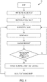
FIG. 4 is a diagram of a third mode of operation of the baler ofFIG. 1 . - Before any embodiments of the disclosure are explained in detail, it is to be understood that the disclosure is not limited in its application to the details of the formation and arrangement of components set forth in the following description or illustrated in the accompanying drawings. The disclosure is capable of supporting other implementations and of being practiced or of being carried out in various ways.
- The disclosure relates to balers and more particularly to balers having a control system configured to calculate the mass of dry matter (DM) contained in a particular bale. More specifically, the baler includes a controller using various sensors to determine the volume and weight of the current bale in addition to the average moisture level of the crop material comprising the bale. Together, the controller uses the collected data to calculate the mass of DM contained in the current forming bale and/or the volume or mass the bale must achieve to produce a desired mass of DM therein. By calculating the mass of DM in the bale, the user is able to more accurately assess the nutritional value contained in the bale. More specifically, only the DM of a bale provides nutritional value to animals as feed. Water or moisture, the other component contributing to the weight of the bale, provides no nutritional value. Therefore, weight alone is insufficient to determine the amount of nutrition a particular bale may provide. As such, the disclosed embodiments remove this uncertainty by determining what percentage of the bale's weight is water and what percentage of the bale's weight is nutritionally valuable DM.
- Referring to
FIG. 1 , a baler 10 includes aframe 14, a set ofwheels 18 mounted to theframe 14, and afeed system 22. The baler 10 also includes abale forming system 26 to collect and processcrop material 30 provided by thefeed system 22, and acontroller 34 to monitor and direct the baling operation. In the illustrated implementation, the baler 10 is a round baler for creatingfinished bales 106 of a crop, such as hay, straw, or other biomasses. - In the illustrated implementation, the
frame 14 of the baler 10 includes a forward housing 42 and adischarge gate 46 pivotably coupled to the forward housing 42 to define avolume 50 therebetween. During use, thedischarge gate 46 is pivotable with respect to the forward housing 42 between a closed position (seeFig. 1 ), in which thevolume 50 is completely enclosed by thedischarge gate 46 and forward housing 42, and an open position (not shown), in which thedischarge gate 46 is pivoted away from the forward housing 42 and thevolume 50 is accessible from the outside. - The
frame 14 of the baler 10 also includes a tow bar ortongue 54 extending from the forward housing 42 and connectable to a towing vehicle (not shown), such as an agricultural tractor or other driven vehicle. The baler 10 may also include a power takeoff shaft (not shown) connectable to the towing vehicle to transmit a rotating drive force from the towing vehicle to various components of the baler 10. In other implementations, the baler 10 may have a dedicated power supply and/or prime mover (not shown), such as an engine, motor, battery, fuel cell, etc., for driving thewheels 18 and for driving and/or powering the various components of the baler 10. - As shown in
FIG. 1 , thefeed system 22 is configured to pick up windrowedcrop material 30 from a support surface 58 (e.g., from a field) and convey thecrop material 30 to thebale forming system 26. In the illustrated implementation, thefeed system 22 includes apickup assembly 62 for collecting thecrop material 30 from thesupport surface 58, and a delivery assembly 66 for directing a continuous stream ofcrop material 30 evenly along the entire width of thebale forming system 26. - Illustrated in
FIG. 1 , thebale forming system 26 is generally a round baling system as is customary in the art. Thebale forming system 26 includes a first set ofrollers 70, a second set ofrollers 74, and one ormore belts 78 supported by the first and second sets ofrollers belt path 82. The size and shape of thebelts 78 extending along thebelt path 82 furthermore defines a variablesize forming chamber 86 within thevolume 50 having aninlet 90 positioned proximate the delivery system 66. During use, the second set ofrollers 74 moves with respect to the first set ofrollers 70 to change the size of the formingchamber 86. - In the illustrated implementation, the second set of
rollers 74 are mounted for rotation on atension arm 94. The tension arm 94, in turn, includes an elongated member having afirst end 98 pivotably coupled to the forward housing 42, and asecond end 102 opposite thefirst end 98. In the illustrated implementation, eachroller 74 of the second set of rollers is rotatably coupled to thetension arm 94 proximate thesecond end 102 such that the rotational motion of thetension arm 94 causes the second set ofrollers 74 to move along an arcuate path within thevolume 50. While the illustrated implementation includes atension arm 94 that is pivotably mounted to the forward housing 42, it is to be understood that in alternative implementations thetension arm 94 may be mounted for translational motion with respect to the first set ofrollers 70. Still further, thetension arm 94 may be configured to include a combination of both rotational and translational movement. - During use, the
tension arm 94 and second set ofrollers 74 are moveable with respect to the first set ofrollers 70 between a first position, in which therollers 74 are located a first distance from theinlet 90 of the formingchamber 86, and a second position, in which therollers 74 are positioned a second distance from theinlet 90 greater than the first distance. Generally speaking, the rotational orientation of thetension arm 94 is dictated by thebale diameter 110 of thebale 106 positioned within the formingchamber 86. In the illustrated implementation, at least oneroller 74 of the second set ofrollers 74 rests against and engages the outerannular surface 112 of thebale 106, acting as a follower. The at least oneroller 74 remains in contact with theouter surface 112 of thebale 106 such that changes inbale diameter 110 cause changes intension arm 94 position. As such, the angular orientation of thetension arm 94 is representative of thebale diameter 110 of thebale 106 positioned in the formingchamber 86. - The
tension arm 94 also includes a biasing member (not shown) to bias thetension arm 94 toward the first position and maintain tension in thebelts 78. In some implementations, the biasing member may include a spring, gas shock, and the like providing a continuous pressure toward the first position. However, in alternative implementations the biasing member may include a hydraulic cylinder, linear actuator, and the like to allow the user to more actively direct the movement of thetension arm 94 within thevolume 50. - During the baling process,
crop material 30 is fed into the formingchamber 86 through theinlet 90 by the delivery assembly 66 of thefeed system 22, creating a cylindricallyshaped bale 106 therein. Thebale 106, in turn, is in contact with and supported along at least a portion of its outerannular surface 112 by thebelts 78 which are held under tension by the tension arm 94 (described above) via therollers 74. During use, thebelts 78 are circulated around thebelt path 82 in direction B, imparting a rotation to thebale 106 in direction C as is customary in the art. Furthermore, the tension in thebelts 78 is configured to apply a radially inward compressive force on theannular wall 112 of thebale 106, compressing thecrop material 30 contained therein. - As
crop material 30 is continuously fed through theinlet 90 and into the formingchamber 86, the rotational motion of thebale 106 results incrop material 30 being deposited along the bale's outerannular surface 112 forming a sort of expanding spiral pattern (seeFIG. 1 ) as is known by those ordinarily skilled in the art. Similarly, the tension within thebelts 78 helps compact the newly appliedcrop material 30 onto the outerannular surface 112 of thebale 106. As a result, the formingbale 106 increases indiameter 110 as the baling process progresses. - As the
bale 106 increases indiameter 110, the at least oneroller 74 of thetension arm 94 in contact with thebale 106 acts as a follower, remaining in contact with theouter surface 112 of the growingbale 106 and causing thetension arm 94 to rotate in direction A away from the first position and toward the second position. As described above, the motion of thetension arm 94, in turn, causes the size of the formingchamber 86 to increase. Thebale 106 andchamber 86 continue to increase in size together until the desiredbale diameter 110 is reached. Once complete, thebale 106 may be wrapped as is well known in the art, and ejected from the rear of the baler 10 via thedischarge gate 46. - After ejecting the completed
bale 106, thetension arm 94 returns to the first position, thereby reducing the size of the formingchamber 86 to its original starting dimensions. The user may then begin the baling process for a subsequent bale. - Illustrated in
FIGS. 1-3 , thecontroller 34 of the baler 10 includes aprocessor 114, amemory unit 118 in operable communication with theprocessor 114, one ormore sensors processor 114, and auser interface 134 in operable communication with theprocessor 114. Theprocessor 114 may also be in operable communication with various elements of the baler 10 such as thebaler tension arm 94, thefeed system 22, thedischarge gate 46, and the like. During use, theprocessor 114 receives signals from the one ormore sensors bale 106 and/or the required dimensions (e.g., diameter) or mass of thebale 106 needed to achieve a desired amount of DM therein. - In particular, the baler 10 includes a bale-
dimension sensor 122, amoisture sensor 126, and one or moremass sensors 130. Thesensors processor 114 may also include additional sensors such as, but not limited to, a discharge gate position sensor and the like. - The bale-
dimension sensor 122 includes a position sensor mounted to thetension arm 94 and configured to detect and output a signal representative of at least one dimension of thebale 106. More specifically, the bale-dimension sensor 122 outputs a signal representative of thebale diameter 110. - In the illustrated implementation, the bale-
dimension sensor 122 detects thebale diameter 110 by monitoring the angular position of thetension arm 94 relative to the forward housing 42. However in alternative implementations, thesensor 122 may be mounted to other elements of the baler 10, such as the forward housing 42, theframe 14, and the like. Still further, in alternative implementations the bale-dimension sensor 122 may be any sensor type able to detect a dimension of thebale 106 either directly (e.g., by directly monitoring the bale itself) or indirectly (e.g., by monitoring the relative position of thetension arm 94 or other elements within the volume 50). Such sensors may include but are not limited to Hall Effect sensors, variable resistance sensors, optical sensors, and the like. - The
moisture sensor 126 includes a sensor mounted to the baler 10 proximate theinlet 90 of the formingchamber 86 that is configured to output a signal representative of the moisture level of thecrop material 30 entering the formingchamber 86. In the illustrated implementation, themoisture sensor 126 is mounted to theframe 14 proximate theinlet 90, however in alternative implementations, themoisture sensor 126 may be incorporated into thefeed system 22, and the like. Themoisture sensor 126 may be any type of sensor able to detect the moisture of thecrop material 30 both directly and indirectly. - The one or more
mass sensors 130 include a series of sensors that, together, are configured to detect the total mass of thebale 106. By way of example only, themass sensors 130 may be positioned between and coupled to both the forward housing 42 and theframe 14. In such implementations, themass sensors 130 may actually weigh the combined weight of thebale 106 and the elements of thebale forming system 26. In other implementations, themass sensors 130 may be coupled to thetongue 54 of theframe 14 and/or to thewheels 18. In still other implementations, themass sensors 130 may be attached to an auxiliary device (not shown) such as an accumulator, a wrapping device, a separate trailer, and the like. In such implementations, themass sensors 130 may be configured to detect the mass of thebale 106 after it has been ejected from thebale forming system 26. - During the baling process, the
processor 114 of the baler 10 receives information regarding the dimensions of thebale 106, the moisture content of thecrop material 30 entering the formingchamber 86 and contained in thebale 106, and the total mass of thebale 106. Using the received information, theprocessor 114 is able to calculate 1) the current bale volume (BaleVol), 2) the average moisture content of thecrop material 30 contained in the bale 106 (BaleMoist), and 3) the mass of DM contained within the bale 106 (DMMass). Using this information, theprocessor 114 provides signals to the user, via theuser interface 134, indicating, among other things, when the desired mass of DM is contained in thebale 106, and/or the dimensions of thebale 106 needed to produce the desired mass of DM therein. - When operating, the
processor 114 calculates the current bale volume (BaleVol) by inputting the current bale diameter (BaleDia), as detected by the bale-dimension sensor 122, and the known width of the forming chamber (ChamberWidth), pre-programmed into thememory 118, into the corresponding bale volume equation:
processor 114 may use different equations tailored to the particular shape and size of the bale being formed. - Furthermore, the
processor 114 calculates the average moisture content of the crop material forming the bale 106 (BaleMoist). For the purposes of this application, the average moisture content of the bale (BaleMoist) is defined as the percentage of the mass of thebale 106 that is produced by water. In some implementations, theprocessor 114 calculates BaleMoist by compiling the running average of the moisture content detected in thecrop material 30 fed into the formingchamber 86 over a pre-determined period of time, i.e., during the creation of thepresent bale 106. In other implementations, theprocessor 114 calculates BaleMoist by compiling the running average of the moisture content detected in thecrop material 30 fed into the formingchamber 86 over the course of baling an entire field. In still other implementations, theprocessor 114 may take into account additional factors such as, but not limited to, the position within the field where thecrop material 30 was collected, the elapsed time since thecrop material 30 was collected, the geological attributes of the field, and the like. - Still further, the
processor 114 calculates the total mass of the bale (BaleMass) by comparing weight readings provided by the one or moremass sensors 130 in two different configurations. More specifically, theprocessor 114 subtracts the mass reading of the baler 10 taken without abale 106 positioned within the forming chamber 86 (BalerEmpty) from the weight reading taken with thebale 106 positioned in the forming chamber 86 (BalerFull). (BaleMass = BalerFull - BalerEmpty). In some embodiments, theprocessor 114 may recalibrate the empty weight of the baler 10 (BalerEmpty) to compensate for changes in inclination, consumption of consumables (e.g., use of wrap material, loss of hydraulic fluid), and the like. In still other implementations, themass sensors 130 may be positioned such that they more directly measure the weight of thebale 106, in such implementations the need to calibrate or calculate the total mass of the bale itself may be reduced. In still other implementations, themass sensors 130 may be positioned on exterior devices (described above) such that the weight of those devices would need to be taken into account. - As illustrated in
FIG. 2 , a firstoperational mode 300 of theprocessor 114 begins with the user entering into theuser interface 134 the mass of DM the user wants thebale 106 to contain (i.e., the Desired DM Mass or (DeDMMass)). The user also enters a target bale dimension the user estimates will contain the Desired DM Mass. In the present implementation, the target bale dimension is the bale diameter 110 (i.e., the User Diameter Estimate or (DiEst)). - With the initial information entered, the baler 10 begins the baling process. During the baling process,
crop material 30 is collected from thesupport surface 58 by thefeed system 22 and directed into the formingchamber 86 to form abale 106 therein (described above). As the baling process proceeds, theprocessor 114 continuously receives signals from the bale-dimension sensor 122 and themoisture sensor 126. From this information, theprocessor 114 is able to continuously calculate the current bale volume (BaleVol) and the average moisture content of thecrop material 30 contained in the bale 106 (BaleMoist). - For the first bale in the series, the baler 10 continues the baling process until the current bale includes a predetermined attribute, which in the first operational mode is a
bale diameter 110 that is equal to the User Diameter Estimate (DiEst). Once achieved, theprocessor 114 stops the baling process by sending an appropriate signal to the user via theuser interface 134. In alternative implementations, the predetermined attribute may also include, but is not limited to, a predetermined dimension, a predetermined total mass, a predetermined DM mass, and the like. - With the baling process stopped, the
processor 114 then takes one or more readings using themass sensors 130 to determine the bale's total mass (BaleMass; described above). Once weighed, the baler 10 wraps thebale 106 and ejects the bale from the formingchamber 86. - With the
bale 106 ejected, theprocessor 114 calculates the mass of DM (DMMass) that was contained in theprevious bale 106 by entering the calculated mass (BaleMass) and average moisture content (BaleMoist) into the following equation:
- If the calculated mass of DM (DMMass) meets or exceeds the Desired DM Mass (DeDMMass), the
processor 114 resumes the baling process and begins creation of asecond bale 106 as described above (e.g., using the (DiEst) as the target bale size or predetermined attribute). However, if the calculated mass of DM in the bale 10 (DMMass) is below the Desired DM Mass (DeDMMass), theprocessor 114 calculates a new predetermined attribute or target bale diameter (TD) taking into consideration the newly acquired data. More specifically, theprocessor 114 calculates a new target diameter (TD) by entering the calculated mass of DM in the bale (DMMass), the calculated volume of the bale (BaleVol), and the desired mass (DeDMMass) into the following equation:
- Simplified in view of the user inputs (e.g., the estimated bale dimension), the new target diameter (TD) can also be calculated using the following equation:

- Once calculated, the
processor 114 replaces the Estimated Bale diameter with the new calculated Target Diameter (TD) and resets the baler 10 to begin forming a second bale. Theprocessor 114 then resumes the baling process using the Target Diameter (TD), instead of the user diameter estimate (DiEst), as the predetermined attribute, as described above. Theprocessor 114 will then re-evaluate the Target Diameter (TD) after each subsequent bale is created, adjusting the Target Diameter (TD) as necessary to adjust for changing crop conditions. - It is to be understood that while the first
operational mode 300 indicates that thefirst bale 106 be ejected before theprocessor 114 calculates the mass of DM (DMMass) of said bale, in alternative implementations the calculations may occur with thebale 106 still positioned in the formingchamber 86. In such embodiments, if thebale 106 is found to contain a mass of DM (DMMass) that is less than the Desired DM Mass (DeDMMass), then thebaler 106 may resume baling with thesame bale 106 remaining in the formingchamber 86, thereby allowing thebale 106 to be enlarged until it achieves the newly calculated target diameter (TD). Still further, in some implementations, theprocessor 114 may be configured to update the target diameter (TD) anytime the calculated dry matter mass (DMMass) falls outside a pre-determined range, regardless of whether the mass is higher or lower than the desired DM Mass (DeDMMass). - As illustrated in
FIG. 3 , a secondoperational mode 304 of theprocessor 114 begins with the user entering into theuser interface 134 the mass of DM the user wants thebale 106 to contain (i.e., the Desired DM Mass or (DeDMMass)). - With the initial information entered, the baler 10 begins the baling process. During the baling process,
crop material 30 is collected from thesupport surface 58 by thefeed system 22 and directed into the formingchamber 86 to form abale 106 therein (described above). As the baling process proceeds, theprocessor 114 continuously receives signals from the one or moremass sensors 130 and themoisture sensor 126. From this information, theprocessor 114 is able to continuously calculate the current bale weight (BaleMass), the average moisture content of thecrop material 30 contained in the bale 106 (BaleMoist), and the mass of DM contained in the current bale 106 (DMMass) using the equation below:
- The baler 10 continues the baling process until the
bale 106 includes the predetermined attribute, which in the second operational mode includes is a mass of DM contained in the bale 106 (DMMass) that is equal to the Desired DM Mass entered by the user (DeDMMass). Once achieved, theprocessor 114 stops the baling process by sending an appropriate signal to the user via theuser interface 134. The baler 10 wraps thebale 106 and ejects the bale from the formingchamber 86. The baler 10 then resets and the process begins anew. - As illustrated in
FIG. 4 , a thirdoperational mode 308 of theprocessor 114 begins with the user entering into theuser interface 134 the mass of DM the user wants thebale 106 to contain (i.e., the Desired DM Mass (DeDMMass)). Theprocessor 114 also imports an estimated bale density (EsBDen). In the illustrated implementation, the estimated bale density (EsBDen) may be manually entered by the user or calculated from bales formed previously. In alternative implementations, the estimated bale density (EsBDen) may be drawn from a pre-calculated table taking into consideration, at least in part, the type of crop being baled, the type of baler being used, the weather, the anticipated moisture level in the crop material, and the like. - With the initial information entered, the baler 10 begins the baling process. During the baling process,
crop material 30 is collected from thesupport surface 58 by thefeed system 22 and directed into the formingchamber 86 to form abale 106 therein (described above). As the baling process proceeds, theprocessor 114 continuously receives signals from the bale-dimension sensor 122 and themoisture sensor 126. From this information, theprocessor 114 is able to continuously determine the current bale volume (BaleVol), and the average moisture content of thecrop material 30 contained in the bale 106 (BaleMoist) as described above. - Using the current bale volume (BaleVol), the average moisture content (BaleMoist), and the estimated bale density (EsBDen), the
processor 114 is able to calculate an estimated DM Mass (EsDMMass) currently contained in the bale using the following equation:
- The baler 10 continues the baling process until the bale includes the predetermined attribute, which in the third operational mode includes an estimated mass of DM contained in the bale 106 (EsDMMass) that is equal to the Desired DM Mass (DeDMMass) entered by the user. Once achieved, the
processor 114 stops the baling process by sending an appropriate signal to the user via theuser interface 134. The baler 10 then weighs thebale 106 using themass sensors 130, wraps thebale 106, and ejects the bale from the formingchamber 86. With thebale 106 ejected, theprocessor 114 then uses the measured bale mass (BaleMass) to calculate the actual bale density (ActBDen) using the following equation:
- The processor 116 may then use the actual bale density (ActBDen) to update the estimated bale density (EsBDen). In doing so, the processor 116 may replace the estimated bale density (EsBDen) outright or may incorporate the new information into the estimated bale density (EsBDen) using an algorithm. With the estimated bale density updated, the baler 10 then resets and the process begins anew.
- It is to be understood that while the third
operational mode 308 ejects thebale 106 once the estimated mass of DM (EsDMMass) is equal to the Desired DM Mass (DeDMMass), in alternative implementations theprocessor 114 may weigh the bale (as described above) before it is ejected to update the estimated bale density (EsBDen) and to compare the estimated Bale mass (EsBaleMass) with the actual bale mass (EsBaleMass). In such implementations, theprocessor 114 may then adjust the estimated bale density (EsBDen) based on the actual bale density or increase the size of thebale 106 until the actual bale mass is equal to the Desired DM.
Claims (9)
- A system comprising:a baler (10) configured to produce a bale (106) having a predetermined dimension;a mass sensor (130) configured to measure a total mass of the bale (106);a bale-dimension sensor (122) configured to measure a dimension of the bale (106);a moisture sensor (126) configured to measure a moisture content of the bale (106); anda controller (34) configured to:calculate an actual dry matter mass (DMMass) of the bale (106);characterized in thatthe controller is further configured to compare a desired dry matter mass (DeDMMass) to the actual dry matter mass (DMMass) of the bale (106); andadjust the predetermined dimension based at least in part on the comparison of the desired dry matter mass (DeDMMass) to the actual dry matter mass (DMMass) of the bale (106).
- The system of claim 1, wherein the bale-dimension sensor (122) is configured to measure a bale diameter (110).
- The system of claim 1 or 2, wherein the predefined dimension is adjusted based at least in part upon the ratio of the actual dry matter mass (DMMass) to the desired dry matter mass (DeDMMass).
- The system in accordance with any one of the preceding claims, wherein the predefined dimension is adjusted based at least in part on the density of the bale (106).
- The system in accordance with any one of the preceding claims, wherein the predefined dimension is a bale diameter (110).
- The system in accordance with any one of the preceding claims, wherein the desired dry matter mass (DeDMMass) is input into the controller (34) via a user interface (134).
- The system in accordance with any one of the preceding claims, wherein the actual dry matter mass (DMMass) of the bale (106) is calculated based at least in part on the total mass of the bale (106) and the moisture content of the bale (106).
- A method of forming a bale (106) with a baler (10) having a controller (34), the method comprising:receiving a signal indicating the moisture content of the bale (106);receiving a signal indicating the total mass of the bale (106);calculating the actual dry matter mass (DMMass) of the bale (106) based at least in part on the moisture content of the bale (106) and the total mass of the bale (106);characterized by comparing the actual dry matter mass (DMMass) of the bale (106) to a desired dry matter mass (DeDMMass) of the bale (106); andadjusting a first attribute of the bale (106) based at least in part on the comparison of the actual dry matter mass (DMMass) and the desired dry matter mass (DeDMMass).
- A system comprising:a baler (10) configured to produce a bale (106) having a predetermined attribute;a force sensor configured to detect a total mass of the bale (106);a moisture sensor (126) configured to measure a moisture content of the bale (106); anda controller (34) configured to:calculate the actual dry matter mass (DMMass) of the bale (106) based at least in part on the total mass of the bale (106) and the moisture content of the bale (106);characterized in thatthe controller is further configured tocompare a desired dry matter mass (DeDMMass) to the actual dry matter mass; andadjust the predetermined attribute for a successive bale (106) based at least in part on the comparison of the desired dry matter mass (DeDMMass) and the actual dry matter mass (DMMass).
Applications Claiming Priority (3)
| Application Number | Priority Date | Filing Date | Title |
|---|---|---|---|
| US201762566784P | 2017-10-02 | 2017-10-02 | |
| US201762566855P | 2017-10-02 | 2017-10-02 | |
| US15/988,910 US10925217B2 (en) | 2017-10-02 | 2018-05-24 | Baler with dry matter content detection system |
Publications (2)
| Publication Number | Publication Date |
|---|---|
| EP3461323A1 EP3461323A1 (en) | 2019-04-03 |
| EP3461323B1 true EP3461323B1 (en) | 2021-03-10 |
Family
ID=63708227
Family Applications (1)
| Application Number | Title | Priority Date | Filing Date |
|---|---|---|---|
| EP18197490.8A Active EP3461323B1 (en) | 2017-10-02 | 2018-09-28 | Baler with dry matter content detection system |
Country Status (2)
| Country | Link |
|---|---|
| US (1) | US10925217B2 (en) |
| EP (1) | EP3461323B1 (en) |
Families Citing this family (4)
| Publication number | Priority date | Publication date | Assignee | Title |
|---|---|---|---|---|
| CN111272266B (en) * | 2020-02-10 | 2021-06-29 | 北京农业智能装备技术研究中心 | Square baler bale weight monitoring system and method |
| US11497169B2 (en) * | 2020-02-27 | 2022-11-15 | Cnh Industrial America Llc | Agricultural vehicle with adjustable pickup |
| CN114246067B (en) * | 2021-12-20 | 2023-03-24 | 中国铁建重工集团股份有限公司 | Bundling machine control system and method |
| CN117123601B (en) * | 2023-08-28 | 2024-02-23 | 上海市肺科医院(上海市职业病防治院) | Intelligent smashing treatment device for infusion bag |
Family Cites Families (11)
| Publication number | Priority date | Publication date | Assignee | Title |
|---|---|---|---|---|
| US2796825A (en) | 1954-08-27 | 1957-06-25 | Int Harvester Co | Device for maintaining constant weight bales |
| US5384436A (en) | 1993-06-30 | 1995-01-24 | Pritchard; Gary E. | Apparatus and method for electrically weighing bales in a mobile crop baler |
| DE19906611A1 (en) | 1999-02-17 | 2000-08-24 | Lely Welger Maschinenfabrik Gm | Agricultural baler with a weighing device |
| DE10322333A1 (en) | 2003-05-17 | 2004-12-02 | Deere & Company, Moline | Device for measuring the weight of a bale |
| US7703391B2 (en) * | 2006-07-28 | 2010-04-27 | Vermeer Manufacturing Company | Round baler with scale and moisture meter |
| US8567311B2 (en) * | 2010-10-28 | 2013-10-29 | Deere & Company | Control logic for applying preservative to agricultural bales |
| US8326563B2 (en) | 2010-10-29 | 2012-12-04 | Deere & Company | Method for determining agricultural bale weight |
| US9182269B2 (en) | 2010-10-29 | 2015-11-10 | Deere & Company | Method for determining the weight of an agricultural bale that compensates for un-level terrain and adjusting for the amount of wrapping material used |
| US9297688B2 (en) | 2012-12-21 | 2016-03-29 | Cnh Industrial America Llc | Weighing round bales |
| US9854744B2 (en) | 2014-12-11 | 2018-01-02 | Cnh Industrial America Llc | Adjusting bale density setting based on bale weight and/or moisture |
| EP3036986B1 (en) | 2014-12-24 | 2019-10-16 | CNH Industrial Belgium nv | Weighing round bales |
-
2018
- 2018-05-24 US US15/988,910 patent/US10925217B2/en active Active
- 2018-09-28 EP EP18197490.8A patent/EP3461323B1/en active Active
Non-Patent Citations (1)
| Title |
|---|
| None * |
Also Published As
| Publication number | Publication date |
|---|---|
| US10925217B2 (en) | 2021-02-23 |
| EP3461323A1 (en) | 2019-04-03 |
| US20190098836A1 (en) | 2019-04-04 |
| BR102018068236A2 (en) | 2019-04-16 |
Similar Documents
| Publication | Publication Date | Title |
|---|---|---|
| EP3461323B1 (en) | Baler with dry matter content detection system | |
| EP3031317B1 (en) | Adjusting bale density setting based on bale weight and/or moisture | |
| EP3315016B1 (en) | Round baler and method of creating a yield map for such a round baler | |
| US7287365B2 (en) | Baler | |
| EP2777383B1 (en) | Bale forming control system and method | |
| US5444969A (en) | Round baler apparatus for monitoring bale shape | |
| US20070113533A1 (en) | Feeding device for a field chopper | |
| US9198361B2 (en) | Automatic bale forming chamber speed based on incoming crop mass | |
| US20140013970A1 (en) | Volumetric baling rate monitor for round baler | |
| US11013186B2 (en) | Baler with adjustable pre-compression chamber | |
| US10257987B2 (en) | Feeding system for an agricultural implement | |
| EP3760032B1 (en) | Variable chamber baler | |
| US8516957B1 (en) | Measuring distance for bale size in a round baler | |
| EP3968752A1 (en) | Variable chamber round baler | |
| KR101287852B1 (en) | Round bailing device of realtime weight sensing variable type | |
| EP3679784B1 (en) | Round baler | |
| US10813291B2 (en) | Round baler having an adjustable width | |
| US11013185B2 (en) | Baler with adjustable pre-compression chamber | |
| EP3141106B2 (en) | Operation and control of bottom floor assembly | |
| NL2010688C2 (en) | AGRICULTURAL HARVESTER. | |
| US5605095A (en) | Compaction sensor for round baler | |
| BR102018068236B1 (en) | SYSTEM FOR DETECTING THE AMOUNT OF DRY MATTER IN A BALE, AND METHOD FOR FORMING A BALE | |
| EP4278886A1 (en) | Round baler wrap usage indicator | |
| US11825774B2 (en) | Baler system with preservative monitoring | |
| US20190327901A1 (en) | Agricultural roundbaler and method for operating an agricultural roundbaler |
Legal Events
| Date | Code | Title | Description |
|---|---|---|---|
| PUAI | Public reference made under article 153(3) epc to a published international application that has entered the european phase |
Free format text: ORIGINAL CODE: 0009012 |
|
| STAA | Information on the status of an ep patent application or granted ep patent |
Free format text: STATUS: THE APPLICATION HAS BEEN PUBLISHED |
|
| AK | Designated contracting states |
Kind code of ref document: A1 Designated state(s): AL AT BE BG CH CY CZ DE DK EE ES FI FR GB GR HR HU IE IS IT LI LT LU LV MC MK MT NL NO PL PT RO RS SE SI SK SM TR |
|
| AX | Request for extension of the european patent |
Extension state: BA ME |
|
| STAA | Information on the status of an ep patent application or granted ep patent |
Free format text: STATUS: REQUEST FOR EXAMINATION WAS MADE |
|
| 17P | Request for examination filed |
Effective date: 20191004 |
|
| RBV | Designated contracting states (corrected) |
Designated state(s): AL AT BE BG CH CY CZ DE DK EE ES FI FR GB GR HR HU IE IS IT LI LT LU LV MC MK MT NL NO PL PT RO RS SE SI SK SM TR |
|
| GRAP | Despatch of communication of intention to grant a patent |
Free format text: ORIGINAL CODE: EPIDOSNIGR1 |
|
| STAA | Information on the status of an ep patent application or granted ep patent |
Free format text: STATUS: GRANT OF PATENT IS INTENDED |
|
| INTG | Intention to grant announced |
Effective date: 20201116 |
|
| GRAS | Grant fee paid |
Free format text: ORIGINAL CODE: EPIDOSNIGR3 |
|
| GRAA | (expected) grant |
Free format text: ORIGINAL CODE: 0009210 |
|
| STAA | Information on the status of an ep patent application or granted ep patent |
Free format text: STATUS: THE PATENT HAS BEEN GRANTED |
|
| AK | Designated contracting states |
Kind code of ref document: B1 Designated state(s): AL AT BE BG CH CY CZ DE DK EE ES FI FR GB GR HR HU IE IS IT LI LT LU LV MC MK MT NL NO PL PT RO RS SE SI SK SM TR |
|
| REG | Reference to a national code |
Ref country code: GB Ref legal event code: FG4D |
|
| REG | Reference to a national code |
Ref country code: AT Ref legal event code: REF Ref document number: 1368740 Country of ref document: AT Kind code of ref document: T Effective date: 20210315 Ref country code: CH Ref legal event code: EP |
|
| REG | Reference to a national code |
Ref country code: DE Ref legal event code: R096 Ref document number: 602018013651 Country of ref document: DE |
|
| REG | Reference to a national code |
Ref country code: IE Ref legal event code: FG4D |
|
| REG | Reference to a national code |
Ref country code: LT Ref legal event code: MG9D |
|
| PG25 | Lapsed in a contracting state [announced via postgrant information from national office to epo] |
Ref country code: GR Free format text: LAPSE BECAUSE OF FAILURE TO SUBMIT A TRANSLATION OF THE DESCRIPTION OR TO PAY THE FEE WITHIN THE PRESCRIBED TIME-LIMIT Effective date: 20210611 Ref country code: HR Free format text: LAPSE BECAUSE OF FAILURE TO SUBMIT A TRANSLATION OF THE DESCRIPTION OR TO PAY THE FEE WITHIN THE PRESCRIBED TIME-LIMIT Effective date: 20210310 Ref country code: FI Free format text: LAPSE BECAUSE OF FAILURE TO SUBMIT A TRANSLATION OF THE DESCRIPTION OR TO PAY THE FEE WITHIN THE PRESCRIBED TIME-LIMIT Effective date: 20210310 Ref country code: BG Free format text: LAPSE BECAUSE OF FAILURE TO SUBMIT A TRANSLATION OF THE DESCRIPTION OR TO PAY THE FEE WITHIN THE PRESCRIBED TIME-LIMIT Effective date: 20210610 Ref country code: NO Free format text: LAPSE BECAUSE OF FAILURE TO SUBMIT A TRANSLATION OF THE DESCRIPTION OR TO PAY THE FEE WITHIN THE PRESCRIBED TIME-LIMIT Effective date: 20210610 Ref country code: LT Free format text: LAPSE BECAUSE OF FAILURE TO SUBMIT A TRANSLATION OF THE DESCRIPTION OR TO PAY THE FEE WITHIN THE PRESCRIBED TIME-LIMIT Effective date: 20210310 |
|
| REG | Reference to a national code |
Ref country code: AT Ref legal event code: MK05 Ref document number: 1368740 Country of ref document: AT Kind code of ref document: T Effective date: 20210310 |
|
| REG | Reference to a national code |
Ref country code: NL Ref legal event code: MP Effective date: 20210310 |
|
| PG25 | Lapsed in a contracting state [announced via postgrant information from national office to epo] |
Ref country code: RS Free format text: LAPSE BECAUSE OF FAILURE TO SUBMIT A TRANSLATION OF THE DESCRIPTION OR TO PAY THE FEE WITHIN THE PRESCRIBED TIME-LIMIT Effective date: 20210310 Ref country code: LV Free format text: LAPSE BECAUSE OF FAILURE TO SUBMIT A TRANSLATION OF THE DESCRIPTION OR TO PAY THE FEE WITHIN THE PRESCRIBED TIME-LIMIT Effective date: 20210310 Ref country code: SE Free format text: LAPSE BECAUSE OF FAILURE TO SUBMIT A TRANSLATION OF THE DESCRIPTION OR TO PAY THE FEE WITHIN THE PRESCRIBED TIME-LIMIT Effective date: 20210310 |
|
| PG25 | Lapsed in a contracting state [announced via postgrant information from national office to epo] |
Ref country code: NL Free format text: LAPSE BECAUSE OF FAILURE TO SUBMIT A TRANSLATION OF THE DESCRIPTION OR TO PAY THE FEE WITHIN THE PRESCRIBED TIME-LIMIT Effective date: 20210310 |
|
| PG25 | Lapsed in a contracting state [announced via postgrant information from national office to epo] |
Ref country code: CZ Free format text: LAPSE BECAUSE OF FAILURE TO SUBMIT A TRANSLATION OF THE DESCRIPTION OR TO PAY THE FEE WITHIN THE PRESCRIBED TIME-LIMIT Effective date: 20210310 Ref country code: EE Free format text: LAPSE BECAUSE OF FAILURE TO SUBMIT A TRANSLATION OF THE DESCRIPTION OR TO PAY THE FEE WITHIN THE PRESCRIBED TIME-LIMIT Effective date: 20210310 Ref country code: SM Free format text: LAPSE BECAUSE OF FAILURE TO SUBMIT A TRANSLATION OF THE DESCRIPTION OR TO PAY THE FEE WITHIN THE PRESCRIBED TIME-LIMIT Effective date: 20210310 Ref country code: AT Free format text: LAPSE BECAUSE OF FAILURE TO SUBMIT A TRANSLATION OF THE DESCRIPTION OR TO PAY THE FEE WITHIN THE PRESCRIBED TIME-LIMIT Effective date: 20210310 |
|
| PG25 | Lapsed in a contracting state [announced via postgrant information from national office to epo] |
Ref country code: SK Free format text: LAPSE BECAUSE OF FAILURE TO SUBMIT A TRANSLATION OF THE DESCRIPTION OR TO PAY THE FEE WITHIN THE PRESCRIBED TIME-LIMIT Effective date: 20210310 Ref country code: RO Free format text: LAPSE BECAUSE OF FAILURE TO SUBMIT A TRANSLATION OF THE DESCRIPTION OR TO PAY THE FEE WITHIN THE PRESCRIBED TIME-LIMIT Effective date: 20210310 Ref country code: PT Free format text: LAPSE BECAUSE OF FAILURE TO SUBMIT A TRANSLATION OF THE DESCRIPTION OR TO PAY THE FEE WITHIN THE PRESCRIBED TIME-LIMIT Effective date: 20210712 Ref country code: PL Free format text: LAPSE BECAUSE OF FAILURE TO SUBMIT A TRANSLATION OF THE DESCRIPTION OR TO PAY THE FEE WITHIN THE PRESCRIBED TIME-LIMIT Effective date: 20210310 Ref country code: IS Free format text: LAPSE BECAUSE OF FAILURE TO SUBMIT A TRANSLATION OF THE DESCRIPTION OR TO PAY THE FEE WITHIN THE PRESCRIBED TIME-LIMIT Effective date: 20210710 |
|
| REG | Reference to a national code |
Ref country code: DE Ref legal event code: R097 Ref document number: 602018013651 Country of ref document: DE |
|
| PLBE | No opposition filed within time limit |
Free format text: ORIGINAL CODE: 0009261 |
|
| STAA | Information on the status of an ep patent application or granted ep patent |
Free format text: STATUS: NO OPPOSITION FILED WITHIN TIME LIMIT |
|
| PG25 | Lapsed in a contracting state [announced via postgrant information from national office to epo] |
Ref country code: ES Free format text: LAPSE BECAUSE OF FAILURE TO SUBMIT A TRANSLATION OF THE DESCRIPTION OR TO PAY THE FEE WITHIN THE PRESCRIBED TIME-LIMIT Effective date: 20210310 Ref country code: DK Free format text: LAPSE BECAUSE OF FAILURE TO SUBMIT A TRANSLATION OF THE DESCRIPTION OR TO PAY THE FEE WITHIN THE PRESCRIBED TIME-LIMIT Effective date: 20210310 Ref country code: AL Free format text: LAPSE BECAUSE OF FAILURE TO SUBMIT A TRANSLATION OF THE DESCRIPTION OR TO PAY THE FEE WITHIN THE PRESCRIBED TIME-LIMIT Effective date: 20210310 |
|
| 26N | No opposition filed |
Effective date: 20211213 |
|
| PG25 | Lapsed in a contracting state [announced via postgrant information from national office to epo] |
Ref country code: SI Free format text: LAPSE BECAUSE OF FAILURE TO SUBMIT A TRANSLATION OF THE DESCRIPTION OR TO PAY THE FEE WITHIN THE PRESCRIBED TIME-LIMIT Effective date: 20210310 |
|
| PG25 | Lapsed in a contracting state [announced via postgrant information from national office to epo] |
Ref country code: IT Free format text: LAPSE BECAUSE OF FAILURE TO SUBMIT A TRANSLATION OF THE DESCRIPTION OR TO PAY THE FEE WITHIN THE PRESCRIBED TIME-LIMIT Effective date: 20210310 |
|
| REG | Reference to a national code |
Ref country code: CH Ref legal event code: PL |
|
| REG | Reference to a national code |
Ref country code: BE Ref legal event code: MM Effective date: 20210930 |
|
| PG25 | Lapsed in a contracting state [announced via postgrant information from national office to epo] |
Ref country code: IS Free format text: LAPSE BECAUSE OF FAILURE TO SUBMIT A TRANSLATION OF THE DESCRIPTION OR TO PAY THE FEE WITHIN THE PRESCRIBED TIME-LIMIT Effective date: 20210710 Ref country code: MC Free format text: LAPSE BECAUSE OF FAILURE TO SUBMIT A TRANSLATION OF THE DESCRIPTION OR TO PAY THE FEE WITHIN THE PRESCRIBED TIME-LIMIT Effective date: 20210310 |
|
| PG25 | Lapsed in a contracting state [announced via postgrant information from national office to epo] |
Ref country code: LU Free format text: LAPSE BECAUSE OF NON-PAYMENT OF DUE FEES Effective date: 20210928 Ref country code: IE Free format text: LAPSE BECAUSE OF NON-PAYMENT OF DUE FEES Effective date: 20210928 Ref country code: BE Free format text: LAPSE BECAUSE OF NON-PAYMENT OF DUE FEES Effective date: 20210930 |
|
| PG25 | Lapsed in a contracting state [announced via postgrant information from national office to epo] |
Ref country code: LI Free format text: LAPSE BECAUSE OF NON-PAYMENT OF DUE FEES Effective date: 20210930 Ref country code: CH Free format text: LAPSE BECAUSE OF NON-PAYMENT OF DUE FEES Effective date: 20210930 |
|
| GBPC | Gb: european patent ceased through non-payment of renewal fee |
Effective date: 20220928 |
|
| PG25 | Lapsed in a contracting state [announced via postgrant information from national office to epo] |
Ref country code: CY Free format text: LAPSE BECAUSE OF FAILURE TO SUBMIT A TRANSLATION OF THE DESCRIPTION OR TO PAY THE FEE WITHIN THE PRESCRIBED TIME-LIMIT Effective date: 20210310 |
|
| PG25 | Lapsed in a contracting state [announced via postgrant information from national office to epo] |
Ref country code: HU Free format text: LAPSE BECAUSE OF FAILURE TO SUBMIT A TRANSLATION OF THE DESCRIPTION OR TO PAY THE FEE WITHIN THE PRESCRIBED TIME-LIMIT; INVALID AB INITIO Effective date: 20180928 |
|
| PG25 | Lapsed in a contracting state [announced via postgrant information from national office to epo] |
Ref country code: GB Free format text: LAPSE BECAUSE OF NON-PAYMENT OF DUE FEES Effective date: 20220928 |
|
| PGFP | Annual fee paid to national office [announced via postgrant information from national office to epo] |
Ref country code: FR Payment date: 20230925 Year of fee payment: 6 Ref country code: DE Payment date: 20230821 Year of fee payment: 6 |