EP2745670A1 - Inclined conveyor assembly with improved swinging axle - Google Patents
Inclined conveyor assembly with improved swinging axle Download PDFInfo
- Publication number
- EP2745670A1 EP2745670A1 EP13192619.8A EP13192619A EP2745670A1 EP 2745670 A1 EP2745670 A1 EP 2745670A1 EP 13192619 A EP13192619 A EP 13192619A EP 2745670 A1 EP2745670 A1 EP 2745670A1
- Authority
- EP
- European Patent Office
- Prior art keywords
- housing
- feederhouse
- roller
- pendulum
- assembly
- Prior art date
- Legal status (The legal status is an assumption and is not a legal conclusion. Google has not performed a legal analysis and makes no representation as to the accuracy of the status listed.)
- Granted
Links
- 238000003306 harvesting Methods 0.000 claims description 12
- 239000004744 fabric Substances 0.000 claims description 6
- 241000282472 Canis lupus familiaris Species 0.000 claims 1
- 230000033001 locomotion Effects 0.000 description 8
- 239000000463 material Substances 0.000 description 5
- 239000010902 straw Substances 0.000 description 5
- 230000008859 change Effects 0.000 description 3
- 229910000639 Spring steel Inorganic materials 0.000 description 2
- 229910000831 Steel Inorganic materials 0.000 description 2
- 238000004140 cleaning Methods 0.000 description 2
- 238000002485 combustion reaction Methods 0.000 description 2
- 230000007246 mechanism Effects 0.000 description 2
- 239000010959 steel Substances 0.000 description 2
- 241000251169 Alopias vulpinus Species 0.000 description 1
- 241001124569 Lycaenidae Species 0.000 description 1
- 241001272996 Polyphylla fullo Species 0.000 description 1
- 240000008042 Zea mays Species 0.000 description 1
- 235000005824 Zea mays ssp. parviglumis Nutrition 0.000 description 1
- 235000002017 Zea mays subsp mays Nutrition 0.000 description 1
- 238000010276 construction Methods 0.000 description 1
- 235000005822 corn Nutrition 0.000 description 1
- 230000001419 dependent effect Effects 0.000 description 1
- 230000010006 flight Effects 0.000 description 1
- 230000005484 gravity Effects 0.000 description 1
- 239000012535 impurity Substances 0.000 description 1
- 238000000034 method Methods 0.000 description 1
- 239000000203 mixture Substances 0.000 description 1
- 239000004033 plastic Substances 0.000 description 1
- 230000008569 process Effects 0.000 description 1
- 230000007704 transition Effects 0.000 description 1
Images


Classifications
-
- B—PERFORMING OPERATIONS; TRANSPORTING
- B65—CONVEYING; PACKING; STORING; HANDLING THIN OR FILAMENTARY MATERIAL
- B65G—TRANSPORT OR STORAGE DEVICES, e.g. CONVEYORS FOR LOADING OR TIPPING, SHOP CONVEYOR SYSTEMS OR PNEUMATIC TUBE CONVEYORS
- B65G41/00—Supporting frames or bases for conveyors as a whole, e.g. transportable conveyor frames
- B65G41/001—Supporting frames or bases for conveyors as a whole, e.g. transportable conveyor frames with the conveyor adjustably mounted on the supporting frame or base
- B65G41/002—Pivotably mounted
-
- A—HUMAN NECESSITIES
- A01—AGRICULTURE; FORESTRY; ANIMAL HUSBANDRY; HUNTING; TRAPPING; FISHING
- A01D—HARVESTING; MOWING
- A01D41/00—Combines, i.e. harvesters or mowers combined with threshing devices
- A01D41/12—Details of combines
- A01D41/14—Mowing tables
- A01D41/16—Devices for coupling mowing tables to conveyors
-
- A—HUMAN NECESSITIES
- A01—AGRICULTURE; FORESTRY; ANIMAL HUSBANDRY; HUNTING; TRAPPING; FISHING
- A01D—HARVESTING; MOWING
- A01D75/00—Accessories for harvesters or mowers
- A01D75/28—Control mechanisms for harvesters or mowers when moving on slopes; Devices preventing lateral pull
- A01D75/287—Control mechanisms for harvesters or mowers when moving on slopes; Devices preventing lateral pull acting on the mowing table
Definitions
- the present invention relates to an inclined conveyor assembly for a combine harvester, comprising: a housing having at its rear end a top inclined conveyor roller rotatably supported by a lower feederhouse roller positioned at the front end of the housing; one about the lower feederhouse roller and the upper feederhouse roller rotating, endless conveyor element with drivers and a hinged at the front end of the housing about a pendulum axis pendulum sign on which a header is fastened.
- Self-propelled combine harvesters include a chassis supported by front driven wheels (or caterpillar tracks) and rear steerable wheels on the ground.
- a feederhouse assembly is arranged, at its front end in turn a header is releasably secured.
- the header can be designed, for example, as a cutting unit with a mowing beam and a reel arranged above it and a transverse auger or cross conveyor belt arranged behind it or as a corn picker with picking units and a transverse auger.
- the header delivers the cut or picked crop to the feeder assembly through a rear discharge opening, which in turn conveys it to the interior of the combine where it is threshed, separated and cleaned.
- the feederhouse assembly includes a housing in which an undershot chain conveyor normally revolves about a lower and an upper feederhouse roller rotatably supported by the housing.
- the lower feederhouse roller is located rearwardly of the discharge opening of the header and the upper feederhouse roller transfers the crop to an (axial or tangential) threshing drum or accelerator roller in the combine.
- feeder conveyor assembly with devisschl ceremonies working conveyor belts ( DE 1 016 975 A ) and an undershot feeder assembly comprising a rubber-fabric belt comprising transversely disposed steel strips engaging the crop from above ( DE 10 2007 049 839 B3 . DE 10 2009 036 104 A1 ).
- Pendulum sign attached at the front end of the feederhouse assembly. It is a frame-shaped element which is hinged on the one hand to a horizontally and extending in the forward direction (real or virtual) swing axle pivotally on the housing of the actual Schräg bankerzusammenbaus and on the other hand, the header is attachable, for example, by upper hooks from above rest against the pendulum sign.
- the shuttle plate allows a pivoting movement of the header relative to the feeder assembly about the horizontal pendulum axis, for example, when driving on a side slope.
- the swivel range must be relatively large, especially when the combine harvester is equipped with height-adjustable front wheels that keep the actual combine harvester and feeder assembly horizontal when driving on a lateral slope.
- the post-published DE 10 2012 200 843 A1 shows a feeder of a combine harvester with a front pendulum blade to which a header is removably attached.
- the shuttle plate is rotatably mounted about a horizontal, extending in the forward direction swing axle relative to the housing of the feederhouse and carries a front feeder roller, which revolves around an endless, flexible conveyor element, which also rotates about a rear feederhouse roller.
- the position of the pendulum axis is chosen in the prior art such that it extends at least approximately horizontally when - the feeder to a rotation axis of the upper feeder roller parallel axis of rotation pivoting - actuators pivots the front end of the feederhouse and the harvesting header to a height above the ground have, which corresponds to a common cutting height.
- a disadvantage of the known in the art orientation of the pendulum axis is that also the distance between a discharge conveyor of the header (at a cutting the transverse auger) and the lower feederhouse roller changes considerably, if this rotatable, but otherwise fixed to the housing of the inclined conveyor is what makes it difficult to transfer the crop from the header to the feederhouse. As a result, the combine harvester is subjected to a layer thickness of the crop that is not homogeneous across the width, which can lead to unsatisfactory work results there as well.
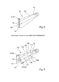
- FIG. 6 shows a feederhouse assembly 20 after DE 10 2012 200 843 A1 with a housing 62 in which an upper feederhouse roller 64 is disposed.
- a shuttle plate 78 is hinged at the front end of the feederhouse assembly 20 by a pivot pin 80 about a horizontal pendulum axis 76 pivotally.
- the lower feederhouse roller 90 is on the shuttle plate 78 rotatably mounted. If the shuttle plate 78 is pivoted about the pendulum axis 76, there are relatively large changes in the distances between the outer ends of the lower feederhouse roller 90, which is marked in the pivoted position with 90 ', and the upper feederhouse roller 74. This change in distance can by the flexible conveyor element to DE 10 2012 200 843 A1 be absorbed only to a limited extent, which restricts the achievable pendulum angle.
- the problem can not be solved by a virtual pendulum axis extending through the center of the pendulum shield 78 or by a pendulum axis on the underside of the pendulum shield, because due to the width of the inclined conveyor rollers 64, 90, the distance between the outer ends of both inclined conveyor rollers changes 64, 90 still significant.
- An inclined conveyor assembly for a combine harvester comprises a housing at the rear end of which an upper feederhouse roller is rotatably mounted. At the front end of the housing, a lower feederhouse roller is arranged. At the front end of the housing is still a pendulum sign on which a header can be removably mounted hinged to a pendulum axis pivotally.
- an endless conveyor element with drivers moves around. The pendulum axis is tilted obliquely backwards and upwards (at a normal working or cutting height and orientation of the header above the ground).
- the pendulum axis is inclined so that the pendulum axis is oriented parallel to an imaginary connecting line between the center of the shuttle (or the center of the lower feeder roller) and the upper feederhouse roll.
- the lower feederhouse roll is rotatably supported on the shuttle blade and an endless, stretchable conveyor element with flights travels around the lower feederhouse roll and around the upper feederhouse roll.
- the lower feeder roller makes the movement of the shuttle (and the header) about the pendulum axis with and the spatial relationship between the header and its discharge opening and the lower feederhouse roller remains constant even with a swung around the pendulum axis header.
- the required mobility between the lower feederhouse roller and the upper feederhouse roller, around which both the endless conveyor element rotates with the drivers, is made possible by the fact that the conveyor element is stretchable. It may in particular be constructed of a rubber-fabric belt on which the drivers are mounted.
- the pendulum axis may be located at the top or bottom of the shuttle sign, i. above the crop stream or below. Alternatively, it may be implemented as a virtual axle with roller bearings between the shuttle blade and the housing.
- the FIG. 1 shows a self-propelled harvester in the form of a combine harvester 10 with a chassis 12, which is supported by driven front wheels 14 and steerable rear wheels 16 on the ground and is moved away from them.
- the wheels 14 are rotated by means not shown drive means in rotation to the combine 10 z. B. to move over a field to be harvested.
- directional details such as front and rear, refer to the direction of travel V of the harvester 10 in the harvesting operation, which in the FIG. 1 goes to the left.
- the front wheels 14 could also be replaced by caterpillar tracks.
- the front wheels 14 or the caterpillar drives) relative to the chassis 12 for horizontally aligning the chassis 12 when driving on a side slope adjustable in height.
- the rear wheels 16 are attached to a pendulum mounted axle to follow the bottom shape.
- a header 18 in the form of a cutting unit is detachably connected to the harvesting operation crop in the form of grain or harvesting other threshable culottes from the field and feeding it up and back by a feeder assembly 20 to a multi-drum threshing mechanism, arranged one after the other in the direction of travel V, a threshing cylinder 22, a stripping drum 24, an uppermost working conveyor drum 26, a tangential separator 28 and a turning drum 30 comprises.
- Downstream of the turning drum 30 is a straw shaker 32.
- the threshing drum 22 is surrounded by a concave 34 in its lower and rear area.
- a finger rake 38 is arranged below the turning drum 30.
- any other threshing and separating device could be used, eg a single tangential threshing drum with following straw walkers or separating rotors or an axial threshing and separating device with one or two axial threshing and separating rotors.
- the mixture containing grains and impurities passing through the threshing concave 34, the separating basket and the straw shakers 32 passes via conveying trays 40, 42 into a cleaning device 46.
- Grain cleaned by the cleaning device 46 is fed by means of a grain screw 48 to an elevator, not shown, which carries it transported a grain tank 50.
- a tailing auger 52 returns unmanaged ear parts through another elevator, not shown, back into the threshing process.
- the chaff may be ejected at the rear of the screen by a rotating chaff spreader, or it may be discharged through a straw chopper (not shown) disposed downstream of the straw walker 32.
- the cleaned grain from the grain tank 50 may be unloaded by a discharge system with cross augers 54 and a discharge conveyor 56.
- the systems mentioned are driven by means of an internal combustion engine 58 and controlled and controlled by an operator from a driver's cab 60.
- the feederhouse assembly 20 includes a housing 62 pivotally coupled to the chassis 12 about the axis of an upper feederhouse roller 64 extending horizontally and transversely to the forward direction.
- the pivoting of the feederhouse assembly 20 about the axis of the upper feederhouse roller 64 is by means of two actuators 66 in the form of hydraulic cylinders located on both sides of the feederhouse assembly 20 at one end at the lower, front end of the chassis 12 and at the other rearward of the front, lower end of the housing 62 of the feeder assembly 20 are hinged to a rectangular frame member 68 (viewed from the front).
- a controller (not shown) controls the actuators 66 during harvesting operation such that the header 18 is to be harvested at a desired height or with a desired bearing force over the bottom of the crop Field is moved.
- the housing 62 of the feederhouse assembly 20 comprises, in a manner known per se, lower and upper walls which are interconnected by lateral walls.
- the lower wall of the housing 62 is at a point 70 which is located approximately half the length of the housing 62, obliquely downwardly bent so that they an upper portion 74 and an opposite the upper portion 74 angled forward and downward, lower Part 72 which is connected at its lower end below an imaginary extension of the upper part 74 of the lower wall of the housing 62 with the rectangular frame member 68.
- Rectangular frame member 68 is rigid or pivotable about a transversely forward and horizontal axis (not shown) to adjust the orientation of header 18 to the particular harvesting conditions and / or dimensions of wheels 14, 16 of combine 10 and elevator assembly 20 connected to the housing 62.
- the rectangular frame member 68 carries a pendulum shield 78 via a pivot pin 80 mounted centrally on the upper horizontal part of the frame member 68.
- the pendulum shield 78 is about a swing axis 76 defined by the pivot pin 80, which in plan view is parallel to the forward direction V and lateral when viewed from above , as in FIG. 1 shown obliquely rearwardly and upwardly, pivotable relative to the frame 68 and the housing 62.
- the pendulum axis 76 is in the illustrated embodiment parallel to an imaginary connecting line 112 between the center of the shuttle plate 78 (ie, the axis of rotation of the lower feeder roller 90) and the axis of rotation of the upper feederhouse roller 64 oriented.
- This inclination of the pendulum axis 76 to the rear and above is particularly provided when an adjustable about a transversely to the forward direction and horizontally extending axis frame member 68 is in a suitable position for normal harvesting operation.
- the pendulum axis 76 may also be further oriented downward or upward and in particular in a region 108, on the one hand by a pendulum axis 76 intersecting parallel 110 to the connecting line 112 between the axis of rotation of the lower feeder roller 90 and the axis of rotation of the upper feederhouse roller 64 and on the other hand by an imaginary connecting line 114 between the oscillating axis 76 and the (underside of the) upper feederhouse roller 64 is limited.
- This area could also be extended symmetrically to the mentioned, the pendulum axis 76 intersecting parallels 110 to the connecting line 112 upwards.
- this area 108 ' is mirrored with respect to the aforementioned area 108 about the connection line 112. Also, this area 108 'could be extended symmetrically to the parallels 110' downwards.
- a mounting frame 86 of the header 18 is supported by hooks 88, the projections 87 of the shuttle plate 78 overlap.
- the header 18 can thus be detached from the shuttle 78 by positioning the header 18 over a suitable tray (e.g., a header truck) and then lowering the elevator assembly 20 by means of the actuators 66, the hooks 88 then disengaging from the shuttle 78.
- the attachment takes place in reverse order and direction. It would also be possible to provide additional bolts between the header 18 and the shuttle blade 78, which can be operated manually or by external force.
- the pivoting of the header 18 and the shuttle plate 78 about the pendulum axis 76 can only be done by gravity, or there are power-operated actuators (not shown) are provided, the pivot angle about the pendulum axis 76 in a conventional manner automatically based on signals from on the Width of the header 18 distributed sensors for detecting the height above the ground and / or the bearing pressure vary.
- a lower feeder roller 90 is rotatably mounted on the shuttle plate 78. Its axis of rotation extends horizontally oriented with horizontally oriented shuttle plate 78 to the forward direction V and horizontal.
- the conveyor element 82 is expandable and preferably comprises a plurality of rubber fabric belts 92 distributed across the width of the housing 62, which are interconnected by the drivers 84 as in FIG FIG. 2 shown. In this case, the arrangement of FIG. 2 be doubled, ie two drivers 84 with the associated rubber fabric belt 92 in the housing 62 may be arranged laterally side by side.
- the drive of the conveying element 82 via attached on its inner side cams, which engage in corresponding recesses in the inclined conveyor rollers 64 and 90, of which at least one of the internal combustion engine 58 is driven forth.
- the drivers 84 are designed as U-shaped steel strips that extend across the width of the housing 62, but could also consist of other material and have a different cross-section.
- threaded bolts 94 are vulcanized into the rubber fabric belts 92.
- the conveyor element 82 is tensioned during operation such that the drivers 84 do not scratch along the bottom of the housing 62 when the pendulum plate 78 is horizontal, which minimizes wear and noise.
- the shuttle plate 78 is in side view, as in the FIG. 1 shown formed approximately trapezoidal or triangular, since the rectangular frame member 68 at the front end of the housing 62 of the feederhouse 20 extends obliquely forward and upward due to the rearwardly and upwardly oriented pendulum axis 76, while the mounting frame 86 of the header 18 in the in FIG. 1 illustrated, normal operating position of the header 18 (corresponding to a normal cutting height) extends approximately vertically and the shuttle plate 78 fills the space therebetween.
- the shuttle blade 78 like the housing 62 of the elevator conveyor assembly 20, has side walls 96 and a bottom 98.
- the shuttle plate 78 is preferably stiffened by frame members (not shown).
- the flexible floor element 100 extends over the entire width of the housing 62.
- the flexible floor element 100 is in the in FIG. 1 embodiment shown made of a flexible material, such as spring steel or rubber.
- the flexible floor element 100 is attached (in each case over its width) at least at the bottom 98 and at the point 70 of the housing 62.
- the flexible floor member 100 may also be slidably coupled to the side walls of the housing 62, for example, by angle elements, not shown, a horizontal, coupled to the flexible bottom member 100 legs and a vertical leg with one or more slots through which a with the Sidewall of the housing 62 connected pin extends.
- the pin could also be attached to the vertical leg and extend through a slot in the side wall of the housing 62.
- the front portion 72 of the lower wall of the housing 62 may be apertured or be executed as a grid construction.
- the rear end of the flexible floor member 100 is at the point 70, however, coupled to the housing 62 of the feederhouse 20 and performs no pendulum motion about the pendulum axis 76.
- the flexible floor element 100 is thus at the pendulum movement of the shuttle blade 78 and the header 18 about the pendulum axis 76 in to be wounded. Due to its flexibility, it can perform this twisting.
- a bottom formed by the bottom member 100 of the feederhouse assembly between the shuttle plate 78 and the point 70 which forms an adaptable to the pendulum angle ramp and a stepless and relatively shallow transition of the crop from the shuttle plate 78 to the rear portion 74 of the housing 62 of Inclined conveyor assembly 20 allows.
- the change in distance between the upper feederhouse roller 64 and the lower feederhouse roller 90 when the shuttle plate 78 oscillates about the pendulum axis 76 remains at a sufficiently low level, which can be absorbed by the elasticity of the conveyor element 82.
- the transfer of goods from the header 18 or shuttle plate 78 is improved in the feederhouse assembly 20.
- sliding elements 102 are mounted above the flexible bottom member 100, which consist of a material (eg plastic) having a smaller coefficient of friction than the flexible material (in particular rubber) of the flexible bottom member 100.
- the sliding elements 102 may be strip-shaped and aligned next to one another in the conveying direction of the crop or arranged transversely thereto one behind the other. They are separately connected to the flexible floor element 100, for example by screws or rivets.
- the flexible floor element 100 is composed of a plurality of overlapping elements 106 which follow one another in the longitudinal direction (ie flow direction of the crop). These elements 106 are attached to support rods 104 extending forwardly V.
- the elements 106 in this embodiment may be made of inherently flexible material such as spring steel or rubber, while the support bars may be inherently rigid or flexible.
- the elements 106 could also be rigid in themselves.
- the elements 106 overlap in the crop flow direction, whereby in the direction of crop flow towards the rear sloping steps arise that do not interfere with the crop flow.
- the elements 106 could also extend in the flow direction, ie be rotated by 90 °.
- the conveyor element 82 be made endless or two ends may be interconnected by suitable means.
- the inclined feed rollers 64, 90 may be provided with a constant over the length of the cross section, as in the FIG. 2 shown, or they comprise a shaft with attached discs on which the conveying element 82 is supported.
- the pendulum axis 78 does not have to be real, but can also be virtual, by supporting the shuttle plate 78 by roller bearings on the frame 68, which makes it possible to place the swing axle 78 in the center of the shuttle plate 72.
Abstract
Description
Die vorliegende Erfindung bezieht sich auf einen Schrägfördererzusammenbau für einen Mähdrescher, mit einem Gehäuse, an dessen rückwärtigen Ende eine obere Schrägfördererwalze drehbar gelagert ist, einer am vorderen Ende des Gehäuses positionierten, unteren Schrägfördererwalze; einem um die untere Schrägfördererwalze und um die obere Schrägfördererwalze umlaufenden, endlosen Förderelement mit Mitnehmern und einem am vorderen Ende des Gehäuses um eine Pendelachse schwenkbar angelenkten Pendelschild, an dem ein Erntevorsatz befestigbar ist.The present invention relates to an inclined conveyor assembly for a combine harvester, comprising: a housing having at its rear end a top inclined conveyor roller rotatably supported by a lower feederhouse roller positioned at the front end of the housing; one about the lower feederhouse roller and the upper feederhouse roller rotating, endless conveyor element with drivers and a hinged at the front end of the housing about a pendulum axis pendulum sign on which a header is fastened.
Selbstfahrende Mähdrescher umfassen ein Fahrgestell, das sich durch vordere, angetriebene Räder (oder Raupenlaufwerke) und rückwärtige, lenkbare Räder auf dem Boden abstützt. An der Vorderseite des Mähdreschers ist ein Schrägfördererzusammenbau angeordnet, an dessen vorderem Ende wiederum ein Erntevorsatz lösbar befestigt ist. Der Erntevorsatz kann beispielsweise als Schneidwerk mit einem Mähwerksbalken und einer darüber angeordneten Haspel und einer dahinter angeordneten Querförderschnecke bzw. einem Querförderband oder als Maispflücker mit Pflückeinheiten und einer Querförderschnecke ausgeführt sein. Beim Erntebetrieb gibt der Erntevorsatz das abgeschnittene oder aufgenommene Erntegut durch eine rückwärtige Abgabeöffnung an den Schrägfördererzusammenbau ab, der es wiederum in das Innere des Mähdreschers fördert, wo es ausgedroschen, getrennt und gereinigt wird.Self-propelled combine harvesters include a chassis supported by front driven wheels (or caterpillar tracks) and rear steerable wheels on the ground. At the front of the combine a feederhouse assembly is arranged, at its front end in turn a header is releasably secured. The header can be designed, for example, as a cutting unit with a mowing beam and a reel arranged above it and a transverse auger or cross conveyor belt arranged behind it or as a corn picker with picking units and a transverse auger. In the harvesting operation, the header delivers the cut or picked crop to the feeder assembly through a rear discharge opening, which in turn conveys it to the interior of the combine where it is threshed, separated and cleaned.
Der Schrägfördererzusammenbau umfasst ein Gehäuse, in dem üblicherweise ein unterschlächtig arbeitender Kettenförderer um eine untere und eine obere Schrägfördererwalze umläuft, die drehbar am Gehäuse gelagert sind. Die untere Schrägfördererwalze ist rückwärtig der Abgabeöffnung des Erntevorsatzes angeordnet und die obere Schrägfördererwalze übergibt das Erntegut einer (Axial- oder Tangential-) Dreschtrommel oder einer Beschleunigerwalze im Mähdrescher.The feederhouse assembly includes a housing in which an undershot chain conveyor normally revolves about a lower and an upper feederhouse roller rotatably supported by the housing. The lower feederhouse roller is located rearwardly of the discharge opening of the header and the upper feederhouse roller transfers the crop to an (axial or tangential) threshing drum or accelerator roller in the combine.
Es wurden auch Schrägfördererzusammenbau mit oberschlächtig arbeitenden Förderbändern (
In vielen Fällen ist am vorderen Ende des Schrägfördererzusammenbaus ein so genannter Pendelschild angebracht. Dabei handelt es sich um ein rahmenförmiges Element, das einerseits um eine sich horizontal und in Vorwärtsrichtung erstreckende (reelle oder virtuelle) Pendelachse schwenkbar am Gehäuse des eigentlichen Schrägfördererzusammenbaus angelenkt ist und an dem andererseits der Erntevorsatz anbringbar ist, beispielsweise durch obere Haken, die von oben her am Pendelschild anliegen. Der Pendelschild ermöglicht eine Schwenkbewegung des Erntevorsatzes gegenüber dem Schrägfördererzusammenbau um die horizontale Pendelachse, beispielsweise beim Befahren eines Seitenhanges. Der Schwenkbereich muss insbesondere dann relativ groß sein, wenn der Mähdrescher mit höhenverstellbaren vordereren Rädern ausgestattet ist, die den eigentlichen Mähdrescher und den Schrägfördererzusammenbau beim Befahren eines seitlichen Hangs horizontal halten. Hierzu sei auf den Stand der Technik nach
Die nachveröffentlichte
Die Lage der Pendelachse ist im Stand der Technik derart gewählt, dass sie zumindest näherungsweise horizontal verläuft, wenn - den Schrägförderer um eine zur Drehachse der oberen Schrägfördererwalze parallele Drehachse verschwenkende - Aktoren das vordere Ende des Schrägförderers und den Erntevorsatz in eine Höhe über dem Boden verschwenkt haben, die einer gebräuchlichen Schnitthöhe entspricht.The position of the pendulum axis is chosen in the prior art such that it extends at least approximately horizontally when - the feeder to a rotation axis of the upper feeder roller parallel axis of rotation pivoting - actuators pivots the front end of the feederhouse and the harvesting header to a height above the ground have, which corresponds to a common cutting height.
Ein Nachteil der im Stand der Technik bekannten Orientierung der Pendelachse liegt darin, dass sich auch der Abstand zwischen einem Abgabeförderer des Erntevorsatzes (bei einem Schneidwerk die Querförderschnecke) und der unteren Schrägfördererwalze beträchtlich ändert, wenn diese drehbar, aber ansonsten unverstellbar am Gehäuse des Schrägförderers befestigt ist, was die Übergabe des Ernteguts vom Erntevorsatz in den Schrägförderer erschwert. Dadurch wird auch der Mähdrescher mit einer über die Breite nicht homogenen Schichtdicke des Ernteguts beaufschlagt, was auch dort zu unbefriedigenden Arbeitsergebnissen führen kann.A disadvantage of the known in the art orientation of the pendulum axis is that also the distance between a discharge conveyor of the header (at a cutting the transverse auger) and the lower feederhouse roller changes considerably, if this rotatable, but otherwise fixed to the housing of the inclined conveyor is what makes it difficult to transfer the crop from the header to the feederhouse. As a result, the combine harvester is subjected to a layer thickness of the crop that is not homogeneous across the width, which can lead to unsatisfactory work results there as well.
Zur Illustration des Standes der Technik wird auf die
Das Problem lässt sich auch nicht durch eine virtuelle, durch die Mitte des Pendelschilds 78 verlaufende Pendelachse oder durch eine Pendelachse an der Unterseite des Pendelschilds lösen, denn aufgrund der Breite der Schrägfördererwalzen 64, 90 ändert sich auch dann der Abstand zwischen den äußeren Enden beider Schrägfördererwalzen 64, 90 immer noch signifikant.The problem can not be solved by a virtual pendulum axis extending through the center of the
Diese geometrischen Probleme ergeben sich auch bei Schrägförderern mit am Gehäuse angebrachten unteren Schrägfördererwalzen, denn dann tritt der Abgabeförderer des Erntevorsatzes näherungsweise an die Stelle der unteren Schrägfördererwalze 90, 90' in der
Es ist eine Aufgabe der vorliegenden Erfindung, die erwähnten Nachteile zu vermeiden.It is an object of the present invention to avoid the disadvantages mentioned.
Diese Aufgabe wird durch die Lehre des Anspruchs 1 gelöst, wobei die abhängigen Ansprüche Merkmale vorteilhafter Ausführungsformen wiedergeben.This object is achieved by the teaching of claim 1, wherein the dependent claims reproduce features of advantageous embodiments.
Ein Schrägfördererzusammenbau für einen Mähdrescher umfasst ein Gehäuse, an dessen rückwärtigem Ende eine obere Schrägfördererwalze drehbar gelagert ist. Am vorderen Ende des Gehäuses ist eine untere Schrägfördererwalze angeordnet. Am vorderen Ende des Gehäuses ist weiterhin ein Pendelschild, an dem ein Erntevorsatz abnehmbar angebracht werden kann, um eine Pendelachse schwenkbar angelenkt. Um die untere Schrägfördererwalze und um die obere Schrägfördererwalze läuft ein endloses Förderelement mit Mitnehmern um. Die Pendelachse ist (bei einer im normalen Erntebetrieb üblichen Arbeits- bzw. Schnitthöhe und Orientierung des Erntevorsatzes über dem Boden) schräg nach hinten und oben geneigt.An inclined conveyor assembly for a combine harvester comprises a housing at the rear end of which an upper feederhouse roller is rotatably mounted. At the front end of the housing, a lower feederhouse roller is arranged. At the front end of the housing is still a pendulum sign on which a header can be removably mounted hinged to a pendulum axis pivotally. Around the lower feederhouse roller and around the upper feederhouse roller, an endless conveyor element with drivers moves around. The pendulum axis is tilted obliquely backwards and upwards (at a normal working or cutting height and orientation of the header above the ground).
Durch die vorgeschlagene Geometrie der Pendelachse erreicht man, dass sich der Abstand zwischen den äußeren Enden des Pendelschilds und dem Gehäuse des Schrägförderers (einschließlich dessen oberer Schrägfördererwalze) beim Verschwenken des Pendelschilds um die Pendelachse wesentlich weniger als im Stand der Technik variiert, was eine über die Breite des Schrägförderers homogene Erntegutübergabe erleichtert. Zur Illustration sei auf die
Vorzugsweise ist die Pendelachse derart geneigt, dass die Pendelachse parallel zu einer gedachten Verbindungslinie zwischen der Mitte des Pendelschilds (bzw. der Mitte der unteren Schrägfördererwalze) und der oberen Schrägfördererwalze orientiert ist.Preferably, the pendulum axis is inclined so that the pendulum axis is oriented parallel to an imaginary connecting line between the center of the shuttle (or the center of the lower feeder roller) and the upper feederhouse roll.
Bei einer bevorzugten Ausführungsform der Erfindung ist die untere Schrägfördererwalze drehbar am Pendelschild abgestützt und ein endloses, dehnbares Förderelement mit Mitnehmern läuft um die untere Schrägfördererwalze und um die obere Schrägfördererwalze um. Dadurch macht die untere Schrägfördererwalze die Bewegung des Pendelschilds (und des Erntevorsatzes) um die Pendelachse mit und die räumliche Relation zwischen dem Erntevorsatz und seiner Abgabeöffnung und der unteren Schrägfördererwalze bleibt auch bei einem um die Pendelachse verschwenktem Erntevorsatz konstant. Die hierfür erforderliche Beweglichkeit zwischen der unteren Schrägfördererwalze und der oberen Schrägfördererwalze, um die beide das endlose Förderelement mit den Mitnehmern umläuft, wird dadurch ermöglicht, dass das Förderelement dehnbar ist. Es kann insbesondere aus einem Gummi-Gewebe-Riemen aufgebaut sein, an dem die Mitnehmer angebracht sind.In a preferred embodiment of the invention, the lower feederhouse roll is rotatably supported on the shuttle blade and an endless, stretchable conveyor element with flights travels around the lower feederhouse roll and around the upper feederhouse roll. Thus, the lower feeder roller makes the movement of the shuttle (and the header) about the pendulum axis with and the spatial relationship between the header and its discharge opening and the lower feederhouse roller remains constant even with a swung around the pendulum axis header. The required mobility between the lower feederhouse roller and the upper feederhouse roller, around which both the endless conveyor element rotates with the drivers, is made possible by the fact that the conveyor element is stretchable. It may in particular be constructed of a rubber-fabric belt on which the drivers are mounted.
Die Pendelachse kann sich an der Ober- oder Unterseite des Pendelschilds befinden, d.h. oberhalb des Erntegutstroms oder darunter. Alternativ kann sie als virtuelle Achse mit Rollenlagern zwischen dem Pendelschild und dem Gehäuse ausgeführt sein.The pendulum axis may be located at the top or bottom of the shuttle sign, i. above the crop stream or below. Alternatively, it may be implemented as a virtual axle with roller bearings between the shuttle blade and the housing.
Diese und andere Aufgaben, Merkmale und Vorteile der vorliegenden Erfindung werden dem Fachmann nach dem Lesen der folgenden detaillierten Beschreibung und angesichts der Zeichnungen offensichtlich.
- Fig. 1
- ist eine Seitenansicht eines Mähdreschers mit einem pendelnd am vorderen Ende des erfindungsgemäßen Schrägfördererzusammenbaus aufgehängten Erntevorsatz.
- Fig. 2
- zeigt eine Draufsicht auf das endlose Förderelement und die Mitnehmer.
- Fig. 3
- ist eine schematische Vorderansicht des Pendelschilds mit der daran befestigten unteren Schrägfördererwalze und dem vorderen Bereich des Schrägfördererzusammenbaus.
- Fig. 4
- zeigt eine vergrößerte Ansicht des Schrägfördererzusammenbaus der
Figur 1 mit einer zweiten Ausführungsform eines flexiblen Bodenelements. - Fig. 5
- zeigt eine Draufsicht auf eine dritte Ausführungsform eines flexiblen Bodenelements.
- Fig. 6
- zeigt eine schematische Seitenansicht eines Schrägfördererzusammenbaus nach dem Stand der Technik, wie er weiter oben diskutiert wurde.
- Fig. 7
- zeigt eine schematische Seitenansicht eines erfindungsgemäßen Schrägfördererzusammenbaus.
- Fig. 1
- is a side view of a combine with a pendulum hanging at the front end of the invention Schrägfördererzusammenbaus header.
- Fig. 2
- shows a plan view of the endless conveyor element and the driver.
- Fig. 3
- Figure 11 is a schematic front view of the shuttle blade with the lower feederhouse roller attached thereto and the forward portion of the feederhouse assembly.
- Fig. 4
- shows an enlarged view of the feederhouse assembly of
FIG. 1 with a second embodiment of a flexible floor element. - Fig. 5
- shows a plan view of a third embodiment of a flexible floor element.
- Fig. 6
- shows a schematic side view of a prior art feederhouse assembly, as discussed above.
- Fig. 7
- shows a schematic side view of an inclined conveyor assembly according to the invention.
Die
An den vorderen Endbereich der Erntemaschine 10 ist ein Erntevorsatz 18 in Form eines Schneidwerks abnehmbar angeschlossen, um beim Erntebetrieb Erntegut in Form von Getreide oder andere, dreschbare Halmfrüchten von dem Feld zu ernten und es nach oben und hinten durch einen Schrägfördererzusammenbau 20 einem Mehrtrommeldreschwerk zuzuführen, das - in Fahrtrichtung V hintereinander angeordnet - eine Dreschtrommel 22, eine Abstreiftrommel 24, eine oberschlächtig arbeitende Fördertrommel 26, einen Tangentialseparator 28 sowie eine Wendetrommel 30 umfasst. Stromab der Wendetrommel 30 befindet sich ein Strohschüttler 32. Die Dreschtrommel 22 ist in ihrem unteren und rückwärtigen Bereich von einem Dreschkorb 34 umgeben. Unterhalb der Fördertrommel 26 ist eine mit Öffnungen versehene oder geschlossene Abdeckung 44 angeordnet, während sich oberhalb der Fördertrommel 26 eine fest stehende Abdeckung und unterhalb des Tangentialseparators 28 ein Separierkorb 36 mit verstellbaren Fingerelementen befindet. Unterhalb der Wendetrommel 30 ist ein Fingerrechen 38 angeordnet. Anstelle des dargestellten Mehrtrommeldreschwerks könnte eine beliebige andere Dresch- und Trenneinrichtung Verwendung finden, z.B. eine einzige Tangentialdreschtrommel mit nachfolgenden Strohschüttlern oder Trennrotoren oder eine Axialdresch- und Trenneinrichtung mit einem oder zwei Axialdresch- und Trennrotoren.At the front end portion of the
Das durch den Dreschkorb 34, den Separierkorb und die Strohschüttler 32 hindurchtretende, Körner und Verunreinigungen enthaltende Gemisch gelangt über Förderböden 40, 42 in eine Reinigungseinrichtung 46. Durch die Reinigungseinrichtung 46 gereinigtes Getreide wird mittels einer Körnerschnecke 48 einem nicht gezeigten Elevator zugeführt, der es in einen Korntank 50 befördert. Eine Überkehrschnecke 52 gibt unausgedroschene Ährenteile durch einen weiteren nicht gezeigten Elevator zurück in den Dreschprozess. Die Spreu kann an der Rückseite der Siebeinrichtung durch einen rotierenden Spreuverteiler ausgeworfen werden, oder sie wird durch einen stromab des Strohschüttlers 32 angeordneten Strohhäcksler (nicht eingezeichnet) ausgetragen. Das gereinigte Getreide aus dem Korntank 50 kann durch ein Entladesystem mit Querschnecken 54 und einem Entladeförderer 56 entladen werden. Die genannten Systeme werden mittels eines Verbrennungsmotors 58 angetrieben und von einem Bediener aus einer Fahrerkabine 60 heraus kontrolliert und gesteuert.The mixture containing grains and impurities passing through the threshing concave 34, the separating basket and the
Der Schrägfördererzusammenbau 20 umfasst ein Gehäuse 62, das um die sich horizontal und quer zur Vorwärtsrichtung erstreckende Achse einer oberen Schrägfördererwalze 64 schwenkbar am Fahrgestell 12 angelenkt ist. Die Verschwenkung des Schrägfördererzusammenbaus 20 um die Achse der oberen Schrägfördererwalze 64 erfolgt mittels zweier Aktoren 66 in Form von Hydraulikzylindern, die auf beiden Seiten des Schrägfördererzusammenbaus 20 einen Endes am unteren, vorderen Ende des Fahrgestells 12 und anderen Endes rückwärtig des vorderen, unteren Endes des Gehäuses 62 des Schrägfördererzusammenbaus 20 an einem (bei Betrachtung von vorn) rechteckigen Rahmenelement 68 angelenkt sind. Eine Steuerung (nicht gezeigt) steuert die Aktoren 66 beim Erntebetrieb derart an, dass der Erntevorsatz 18 in einer gewünschten Höhe oder mit einer gewünschten Auflagekraft über den Boden des abzuerntenden Feldes bewegt wird. Das Gehäuse 62 des Schrägfördererzusammenbaus 20 umfasst in an sich bekannter Weise untere und obere Wände, die durch seitliche Wände untereinander verbunden sind. Die untere Wand des Gehäuses 62 ist an einem Punkt 70, der sich etwa auf der Hälfte der Länge des Gehäuses 62 befindet, schräg nach unten abgeknickt, sodass sie einen oberen Teil 74 und einen gegenüber dem oberen Teil 74 nach vorn und unten abgewinkelten, unteren Teil 72 umfasst, der an seinem unteren Ende unterhalb einer gedachten Verlängerung des oberen Teils 74 der unteren Wand des Gehäuses 62 mit dem rechteckigen Rahmenelement 68 verbunden ist.The
Das rechteckige Rahmenelement 68 ist starr oder zur Anpassung der Orientierung des Erntevorsatzes 18 an die jeweiligen Erntebedingungen und/oder an die Abmessungen der Räder 14, 16 des Mähdreschers 10 und des Schrägfördererzusammenbaus 20 um eine quer zur Vorwärtsrichtung und horizontal verlaufende Achse (nicht gezeigt) schwenkbar mit dem Gehäuse 62 verbunden. Das rechteckige Rahmenelement 68 trägt über einen mittig am oberen, horizontalen Teil des Rahmenelements 68 angebrachten Schwenkstift 80 ein Pendelschild 78. Der Pendelschild 78 ist um eine durch den Schwenkstift 80 definierte Pendelachse 76, die bei Draufsicht von oben parallel zur Vorwärtsrichtung V und bei seitlicher Betrachtung, wie in
Die Pendelachse 76 ist in der dargestellten Ausführungsform parallel zu einer gedachten Verbindungslinie 112 zwischen der Mitte des Pendelschilds 78 (d.h. der Drehachse der unteren Schrägfördererwalze 90) und der Drehachse der oberen Schrägfördererwalze 64 orientiert. Diese Neigung der Pendelachse 76 nach hinten und oben ist insbesondere dann vorgesehen, wenn ein um eine quer zur Vorwärtsrichtung und horizontal verlaufende Achse verstellbares Rahmenelement 68 sich in einer zum normalen Erntebetrieb geeigneten Position befindet. Bei anderen Ausführungsformen der Erfindung oder bei einem um die erwähnte Achse verstellten Rahmenelement 68 kann die Pendelachse 76 auch weiter nach unten oder oben orientiert sein und insbesondere in einem Bereich 108 liegen, der einerseits durch eine die Pendelachse 76 schneidende Parallele 110 zu der Verbindungslinie 112 zwischen der Drehachse der unteren Schrägfördererwalze 90 und der Drehachse der oberen Schrägfördererwalze 64 und anderseits durch eine gedachte Verbindungslinie 114 zwischen der Pendelachse 76 und der (Unterseite der) oberen Schrägfördererwalze 64 begrenzt ist. Dieser Bereich könnte auch symmetrisch zur erwähnten, die Pendelachse 76 schneidenden Parallelen 110 zur Verbindungslinie 112 nach oben erweitert werden. Wenn die Pendelachse 76 sich unterhalb des Pendelschilds 78 befindet, wie in der
Am Pendelschild 78 stützt sich ein Befestigungsrahmen 86 des Erntevorsatzes 18 durch Haken 88 ab, die Vorsprünge 87 des Pendelschilds 78 übergreifen. Der Erntevorsatz 18 kann demnach vom Pendelschild 78 abgenommen werden, indem der Erntevorsatz 18 über einer geeigneten Ablage (z.B. einem Schneidwerkstransportwagen) positioniert und dann der Schrägfördererzusammenbau 20 mittels der Aktoren 66 abgesenkt wird, wobei sich die Haken 88 dann vom Pendelschild 78 lösen. Die Anbringung erfolgt in umgekehrter Reihenfolge und Richtung. Es wäre auch möglich, weitere Riegel zwischen dem Erntevorsatz 18 und dem Pendelschild 78 vorzusehen, die manuell oder durch Fremdkraft betätigt werden können. Die Verschwenkung des Erntevorsatzes 18 und des Pendelschilds 78 um die Pendelachse 76 kann lediglich durch die Schwerkraft erfolgen, oder es sind fremdkraftbetätigte Aktoren (nicht gezeigt) vorgesehen, die den Schwenkwinkel um die Pendelachse 76 in an sich bekannter Weise selbsttätig basierend auf Signalen von über die Breite des Erntevorsatzes 18 verteilten Sensoren zur Erfassung der Höhe über dem Boden und/oder des Auflagedrucks variieren.On
Eine untere Schrägfördererwalze 90 ist drehbar am Pendelschild 78 gelagert. Ihre Drehachse erstreckt sich bei horizontal orientiertem Pendelschild 78 quer zur Vorwärtsrichtung V und horizontal. Um die Schrägfördererwalzen 64, 90 läuft ein endloses Förderelement 82 mit Mitnehmern 84 um, das das Erntegut im Betrieb unterschlächtig fördert. Das Förderelement 82 ist dehnbar und umfasst vorzugsweise mehrere über die Breite des Gehäuses 62 verteilte Gummi-Gewebe-Riemen 92, die untereinander durch die Mitnehmer 84 verbunden sind, wie in der
Der Pendelschild 78 ist in seitlicher Ansicht, wie in der
Zwischen dem Boden 98 des Pendelschilds 78 und dem Punkt 70 zwischen den beiden Teilen 72, 74 der unteren Wand des Gehäuses 62 erstreckt sich ein flexibles Bodenelement 100. Das flexible Bodenelement 100 erstreckt sich über die gesamte Breite des Gehäuses 62. Das flexible Bodenelement 100 ist in der in
Das flexible Bodenelement 100 kann auch verschiebbar mit den seitlichen Wänden des Gehäuses 62 gekoppelt sein, beispielsweise durch nicht gezeigte Winkelelemente, einen horizontalen, mit dem flexiblen Bodenelement 100 gekoppelten Schenkel und einen vertikalen Schenkel mit einem oder mehreren Langlöchern umfassen, durch die sich ein mit der Seitenwand des Gehäuses 62 verbundener Stift erstreckt. Der Stift könnte auch am vertikalen Schenkel befestigt sein und sich durch ein Langloch in der Seitenwand des Gehäuses 62 erstrecken. Dadurch kann eine Abdichtung zwischen dem flexiblen Bodenelement 100 und der Seitenwand des Gehäuses 62 erzielt werden, um zu verhindern, dass signifikante Mengen an Erntegut in den Zwischenraum zwischen dem flexiblen Bodenelement 100 und dem vorderen Teil 72 der unteren Wand des Gehäuses 62 gelangen. Um zu verhindern, dass sich Erntegut im Zwischenraum zwischen dem flexiblen Bodenelement 100 und dem vorderen Teil 72 der unteren Wand des Gehäuses 62 ansammelt und schließlich die Bewegung des flexiblen Bodenelements 100 behindert, kann der vordere Teil 72 der unteren Wand des Gehäuses 62 mit Öffnungen versehen oder als Gitterkonstruktion ausgeführt werden.The
Wie man anhand der
Durch die Neigung der Pendelachse 76 nach oben und hinten bleibt die Abstandsänderung zwischen der oberen Schrägfördererwalze 64 und der unteren Schrägfördererwalze 90 beim Pendeln des Pendelschilds 78 um die Pendelachse 76 in einem hinreichend geringen Maß, das durch die Elastizität des Förderelements 82 aufgenommen werden kann. Außerdem wird dadurch die Gutübergabe vom Erntevorsatz 18 bzw. Pendelschild 78 in den Schrägfördererzusammenbau 20 verbessert.Due to the inclination of the
Bei einer in der
Bei der in der
Es bleibt noch anzumerken, dass das Förderelement 82 endlos hergestellt sein oder zwei Enden aufweisen kann, die durch geeignete Mittel untereinander verbindbar sind. Die Schrägförderwalzen 64, 90 können mit einem über die Länge konstanten Querschnitt versehen sein, wie in der
Claims (7)
Applications Claiming Priority (1)
| Application Number | Priority Date | Filing Date | Title |
|---|---|---|---|
| DE102012223769.0A DE102012223769A1 (en) | 2012-12-19 | 2012-12-19 | Inclined conveyor assembly with improved swing axle |
Publications (2)
| Publication Number | Publication Date |
|---|---|
| EP2745670A1 true EP2745670A1 (en) | 2014-06-25 |
| EP2745670B1 EP2745670B1 (en) | 2016-08-03 |
Family
ID=49578165
Family Applications (1)
| Application Number | Title | Priority Date | Filing Date |
|---|---|---|---|
| EP13192619.8A Active EP2745670B1 (en) | 2012-12-19 | 2013-11-13 | Inclined conveyor assembly with improved swinging axle |
Country Status (3)
| Country | Link |
|---|---|
| US (1) | US9309057B2 (en) |
| EP (1) | EP2745670B1 (en) |
| DE (1) | DE102012223769A1 (en) |
Cited By (1)
| Publication number | Priority date | Publication date | Assignee | Title |
|---|---|---|---|---|
| CN112293060A (en) * | 2019-07-30 | 2021-02-02 | 凯斯纽荷兰(中国)管理有限公司 | Floating roller and floating roller group for agricultural machine and harvesting machine |
Families Citing this family (9)
| Publication number | Priority date | Publication date | Assignee | Title |
|---|---|---|---|---|
| BE1022622B1 (en) * | 2015-03-27 | 2016-06-17 | Cnh Industrial Belgium Nv | Mower mounting frame |
| BE1023925B1 (en) | 2016-03-01 | 2017-09-13 | Cnh Industrial Belgium Nv | FEEDING DEVICE FOR CUTTER |
| GB201607568D0 (en) * | 2016-04-29 | 2016-06-15 | Agco Do Brazil Com E Ind Ltda | Harvester header pitch adjustment apparatus |
| US10405491B2 (en) * | 2017-03-31 | 2019-09-10 | Deere & Company | Slat insert for noise/wear attenuation in a feederhouse conveyor |
| BR102017010857A2 (en) * | 2017-05-24 | 2018-12-18 | CNH Industrial Brasil Ltda. | structural assembly for mounting a platform and harvester |
| US20190200527A1 (en) * | 2017-12-29 | 2019-07-04 | Brian G. Robertson | Conveyor chain slat with brush assembly |
| US11109533B2 (en) * | 2019-07-30 | 2021-09-07 | Cnh Industrial America Llc | Feeder housing for agricultural machine |
| US11326973B2 (en) * | 2019-08-27 | 2022-05-10 | Cnh Industrial America Llc | Method for measuring combine header center of gravity and mass |
| GB201913117D0 (en) | 2019-09-11 | 2019-10-23 | Agco Int Gmbh | Feederhouse assembl having a rotational shaft with fluid passages |
Citations (6)
| Publication number | Priority date | Publication date | Assignee | Title |
|---|---|---|---|---|
| DE1016975B (en) | 1953-09-05 | 1957-10-03 | Dechentreiter Maschinenfabrik | Inclined conveyor for combine harvesters |
| EP0243540A1 (en) * | 1986-05-02 | 1987-11-04 | Ford New Holland N.V. | Header flotation system for an agricultural machine |
| DE29519842U1 (en) | 1995-09-01 | 1996-02-01 | Schwaninger Kurt Ag | Hillside combine |
| DE10018211A1 (en) | 2000-04-12 | 2001-11-22 | Claas Selbstfahr Erntemasch | Agricultural harvester |
| DE102007049839B3 (en) | 2007-10-18 | 2009-06-04 | Ea Broekema Bv Transportbandenfabriek | Rod strap for rod strap conveyor, has rods spaced from each other transverse to conveyor direction and connected with high tensile, flexible straps at ends through rivets, whose shafts pass aligned holes in straps and rods |
| DE102009036104A1 (en) | 2009-07-27 | 2011-02-03 | Artemis Kautschuk- Und Kunststoff-Technik Gmbh | Inclined conveyor for combine harvester |
Family Cites Families (26)
| Publication number | Priority date | Publication date | Assignee | Title |
|---|---|---|---|---|
| US3324637A (en) * | 1964-06-26 | 1967-06-13 | Massey Ferguson Ltd | Combine having quick detachable header |
| NL6502216A (en) * | 1965-02-22 | 1966-08-23 | ||
| AR206682A1 (en) * | 1972-02-14 | 1976-08-13 | Degussa | PROCEDURE FOR THE PREPARATION OF NEW 7-HALOGEN-5-PHENYL-6-AZA-3H-1,4-BENZODIAZEPINES AND 7-HALOGEN-5-PHENYL-6-AZA-1,2-DIHYDRO-3 H-1,4 -BENZODIAZEPINES |
| US4253295A (en) * | 1979-11-05 | 1981-03-03 | Sperry Corporation | Lateral float mechanism for combines |
| US4266392A (en) * | 1979-11-05 | 1981-05-12 | Sperry Corporation | Header cutting angle adjustment mechanism |
| US4266391A (en) * | 1979-11-05 | 1981-05-12 | Sperry Corporation | Header attachment mechanism for combines |
| US4282703A (en) * | 1979-12-10 | 1981-08-11 | Deere & Company | Feeder house for a crop harvester |
| US4527381A (en) * | 1983-10-13 | 1985-07-09 | Sperry Corporation | Lateral flotation mechanism for combine harvesters |
| US4612757A (en) * | 1985-04-12 | 1986-09-23 | Sperry Corporation | Combine header attitude control mechanism |
| US4776153A (en) * | 1986-02-27 | 1988-10-11 | Deere & Company | Automatic height control for a laterally pivoted harvester header |
| DE4127189C2 (en) * | 1991-08-19 | 2001-08-16 | Gustav Schumacher | Control device for an oscillating assembly on an agricultural machine |
| US5359836A (en) * | 1993-02-01 | 1994-11-01 | Control Concepts, Inc. | Agricultural harvester with closed loop header control |
| US5415586A (en) * | 1993-11-17 | 1995-05-16 | R. A. Hanson Company, Inc. | Combine harvester leveling system, combine harvester header adjusting system, and pivoting chain drive system |
| CA2110775C (en) * | 1993-12-06 | 1999-03-02 | Gregory J. Honey | A feeder adapter for mounting a combine header to a feeder housing of a combine |
| US5799483A (en) * | 1996-08-29 | 1998-09-01 | Voss; Douglas A. | Combine harvester header lateral levelling |
| US5918448A (en) * | 1997-02-06 | 1999-07-06 | Agco Corporation | Combine header lateral tilt assembly |
| DE19949213A1 (en) * | 1999-10-13 | 2001-08-09 | Claas Selbstfahr Erntemasch | Device for receiving and holding a cutting unit assembly on the swiveling feeder of a self-propelled combine harvester |
| US6519923B1 (en) * | 2001-09-10 | 2003-02-18 | Case Corporation | System for coupling, uncoupling and controlling the header assembly in an agricultural combine |
| US6735929B2 (en) * | 2002-03-18 | 2004-05-18 | Deere & Company | Multifunction latch for a combine |
| DE10227484A1 (en) * | 2002-06-19 | 2004-02-26 | Claas Selbstfahrende Erntemaschinen Gmbh | Device and method for controlling the position of a harvesting device of agricultural harvesting machines |
| US7430846B2 (en) * | 2005-05-10 | 2008-10-07 | Deere & Company | Floating header with integrated float system for use with an agricultural windrower or combine |
| US7222475B2 (en) * | 2005-05-10 | 2007-05-29 | Deere & Company | Header hydraulic float system |
| US7870709B2 (en) * | 2009-02-25 | 2011-01-18 | Chn America Llc | Automatic lateral tilt control of a header in stubble height mode using machine level sensor |
| BE1019635A3 (en) * | 2010-02-02 | 2012-09-04 | Cnh Belgium Nv | AGRICULTURAL MACHINE WITH AUTOMATIC COUPLING. |
| DE102010028605A1 (en) * | 2010-05-05 | 2011-11-10 | Deere & Company | Drive arrangement for a header of a harvester |
| DE102013200235A1 (en) | 2012-01-20 | 2013-07-25 | Deere & Company | Inclined conveyor assembly for a combine harvester |
-
2012
- 2012-12-19 DE DE102012223769.0A patent/DE102012223769A1/en not_active Withdrawn
-
2013
- 2013-11-13 EP EP13192619.8A patent/EP2745670B1/en active Active
- 2013-12-18 US US14/133,346 patent/US9309057B2/en active Active
Patent Citations (6)
| Publication number | Priority date | Publication date | Assignee | Title |
|---|---|---|---|---|
| DE1016975B (en) | 1953-09-05 | 1957-10-03 | Dechentreiter Maschinenfabrik | Inclined conveyor for combine harvesters |
| EP0243540A1 (en) * | 1986-05-02 | 1987-11-04 | Ford New Holland N.V. | Header flotation system for an agricultural machine |
| DE29519842U1 (en) | 1995-09-01 | 1996-02-01 | Schwaninger Kurt Ag | Hillside combine |
| DE10018211A1 (en) | 2000-04-12 | 2001-11-22 | Claas Selbstfahr Erntemasch | Agricultural harvester |
| DE102007049839B3 (en) | 2007-10-18 | 2009-06-04 | Ea Broekema Bv Transportbandenfabriek | Rod strap for rod strap conveyor, has rods spaced from each other transverse to conveyor direction and connected with high tensile, flexible straps at ends through rivets, whose shafts pass aligned holes in straps and rods |
| DE102009036104A1 (en) | 2009-07-27 | 2011-02-03 | Artemis Kautschuk- Und Kunststoff-Technik Gmbh | Inclined conveyor for combine harvester |
Cited By (1)
| Publication number | Priority date | Publication date | Assignee | Title |
|---|---|---|---|---|
| CN112293060A (en) * | 2019-07-30 | 2021-02-02 | 凯斯纽荷兰(中国)管理有限公司 | Floating roller and floating roller group for agricultural machine and harvesting machine |
Also Published As
| Publication number | Publication date |
|---|---|
| DE102012223769A1 (en) | 2014-06-26 |
| US9309057B2 (en) | 2016-04-12 |
| US20140166433A1 (en) | 2014-06-19 |
| EP2745670B1 (en) | 2016-08-03 |
Similar Documents
| Publication | Publication Date | Title |
|---|---|---|
| EP2745670B1 (en) | Inclined conveyor assembly with improved swinging axle | |
| EP2745671B1 (en) | Inclined conveyor assembly with flexible base | |
| EP1721512B1 (en) | Cutting device with a belt conveyor assembly | |
| EP1444881B1 (en) | Drive system for the harvesting attachment of a harvesting machine | |
| DE60222881T2 (en) | SHELF CONVEYOR FOR AGRICULTURAL HARVEST | |
| DE10302692B4 (en) | Drive system for a header of a harvester | |
| EP2957164B1 (en) | Inclined conveyor assembly for a combine harvester | |
| EP2591664A1 (en) | Sieve for a cleaning device of a combine harvester | |
| DE102005016350A1 (en) | Harvest header for agricultural harvesters | |
| EP0933017A1 (en) | Transporting device with rotating and at least driving element and harvester with such a transporting device | |
| DE102013226436B4 (en) | Feederhouse for a combine harvester | |
| DE1507384A1 (en) | thresher | |
| DE102020204860A1 (en) | WEATHER STATION BRACKET FOR HARVESTING MACHINE AND PROCEDURE FOR EXTENDING THE BRACKET | |
| EP2708107B1 (en) | Self-propelled combine harvester | |
| DE2317048A1 (en) | HARVESTER | |
| BE1023463B1 (en) | Harvest header with side cover | |
| EP2617280A1 (en) | Feeder assembly for a combine harvester | |
| EP3028560B1 (en) | Concave assembly for a combine harvester | |
| EP3659421B1 (en) | Harvesting header with adjustable transverse auger | |
| EP1595434B1 (en) | Reel arrangement | |
| BE1022970B1 (en) | Adjustment arrangement for adjusting the working gap of a basket of a threshing and / or separating device | |
| EP1894463B1 (en) | Agricultural harvester with an excess load device | |
| DE1925933A1 (en) | Grain and straw conveyors for combine harvesters | |
| EP1530895B1 (en) | Combined harvester stone trap | |
| EP2764766A1 (en) | Thresher with a turning drum and a stripping roller |
Legal Events
| Date | Code | Title | Description |
|---|---|---|---|
| PUAI | Public reference made under article 153(3) epc to a published international application that has entered the european phase |
Free format text: ORIGINAL CODE: 0009012 |
|
| 17P | Request for examination filed |
Effective date: 20131113 |
|
| AK | Designated contracting states |
Kind code of ref document: A1 Designated state(s): AL AT BE BG CH CY CZ DE DK EE ES FI FR GB GR HR HU IE IS IT LI LT LU LV MC MK MT NL NO PL PT RO RS SE SI SK SM TR |
|
| AX | Request for extension of the european patent |
Extension state: BA ME |
|
| R17P | Request for examination filed (corrected) |
Effective date: 20150105 |
|
| RBV | Designated contracting states (corrected) |
Designated state(s): AL AT BE BG CH CY CZ DE DK EE ES FI FR GB GR HR HU IE IS IT LI LT LU LV MC MK MT NL NO PL PT RO RS SE SI SK SM TR |
|
| GRAP | Despatch of communication of intention to grant a patent |
Free format text: ORIGINAL CODE: EPIDOSNIGR1 |
|
| RAP1 | Party data changed (applicant data changed or rights of an application transferred) |
Owner name: DEERE & COMPANY |
|
| INTG | Intention to grant announced |
Effective date: 20160330 |
|
| GRAS | Grant fee paid |
Free format text: ORIGINAL CODE: EPIDOSNIGR3 |
|
| GRAA | (expected) grant |
Free format text: ORIGINAL CODE: 0009210 |
|
| AK | Designated contracting states |
Kind code of ref document: B1 Designated state(s): AL AT BE BG CH CY CZ DE DK EE ES FI FR GB GR HR HU IE IS IT LI LT LU LV MC MK MT NL NO PL PT RO RS SE SI SK SM TR |
|
| REG | Reference to a national code |
Ref country code: GB Ref legal event code: FG4D Free format text: NOT ENGLISH |
|
| REG | Reference to a national code |
Ref country code: CH Ref legal event code: EP Ref country code: AT Ref legal event code: REF Ref document number: 816721 Country of ref document: AT Kind code of ref document: T Effective date: 20160815 |
|
| REG | Reference to a national code |
Ref country code: IE Ref legal event code: FG4D Free format text: LANGUAGE OF EP DOCUMENT: GERMAN |
|
| REG | Reference to a national code |
Ref country code: DE Ref legal event code: R096 Ref document number: 502013003927 Country of ref document: DE |
|
| REG | Reference to a national code |
Ref country code: NL Ref legal event code: MP Effective date: 20160803 |
|
| REG | Reference to a national code |
Ref country code: LT Ref legal event code: MG4D |
|
| PG25 | Lapsed in a contracting state [announced via postgrant information from national office to epo] |
Ref country code: NO Free format text: LAPSE BECAUSE OF FAILURE TO SUBMIT A TRANSLATION OF THE DESCRIPTION OR TO PAY THE FEE WITHIN THE PRESCRIBED TIME-LIMIT Effective date: 20161103 Ref country code: RS Free format text: LAPSE BECAUSE OF FAILURE TO SUBMIT A TRANSLATION OF THE DESCRIPTION OR TO PAY THE FEE WITHIN THE PRESCRIBED TIME-LIMIT Effective date: 20160803 Ref country code: HR Free format text: LAPSE BECAUSE OF FAILURE TO SUBMIT A TRANSLATION OF THE DESCRIPTION OR TO PAY THE FEE WITHIN THE PRESCRIBED TIME-LIMIT Effective date: 20160803 Ref country code: LT Free format text: LAPSE BECAUSE OF FAILURE TO SUBMIT A TRANSLATION OF THE DESCRIPTION OR TO PAY THE FEE WITHIN THE PRESCRIBED TIME-LIMIT Effective date: 20160803 Ref country code: IS Free format text: LAPSE BECAUSE OF FAILURE TO SUBMIT A TRANSLATION OF THE DESCRIPTION OR TO PAY THE FEE WITHIN THE PRESCRIBED TIME-LIMIT Effective date: 20161203 Ref country code: NL Free format text: LAPSE BECAUSE OF FAILURE TO SUBMIT A TRANSLATION OF THE DESCRIPTION OR TO PAY THE FEE WITHIN THE PRESCRIBED TIME-LIMIT Effective date: 20160803 Ref country code: FI Free format text: LAPSE BECAUSE OF FAILURE TO SUBMIT A TRANSLATION OF THE DESCRIPTION OR TO PAY THE FEE WITHIN THE PRESCRIBED TIME-LIMIT Effective date: 20160803 |
|
| PG25 | Lapsed in a contracting state [announced via postgrant information from national office to epo] |
Ref country code: LV Free format text: LAPSE BECAUSE OF FAILURE TO SUBMIT A TRANSLATION OF THE DESCRIPTION OR TO PAY THE FEE WITHIN THE PRESCRIBED TIME-LIMIT Effective date: 20160803 Ref country code: PL Free format text: LAPSE BECAUSE OF FAILURE TO SUBMIT A TRANSLATION OF THE DESCRIPTION OR TO PAY THE FEE WITHIN THE PRESCRIBED TIME-LIMIT Effective date: 20160803 Ref country code: SE Free format text: LAPSE BECAUSE OF FAILURE TO SUBMIT A TRANSLATION OF THE DESCRIPTION OR TO PAY THE FEE WITHIN THE PRESCRIBED TIME-LIMIT Effective date: 20160803 Ref country code: ES Free format text: LAPSE BECAUSE OF FAILURE TO SUBMIT A TRANSLATION OF THE DESCRIPTION OR TO PAY THE FEE WITHIN THE PRESCRIBED TIME-LIMIT Effective date: 20160803 Ref country code: GR Free format text: LAPSE BECAUSE OF FAILURE TO SUBMIT A TRANSLATION OF THE DESCRIPTION OR TO PAY THE FEE WITHIN THE PRESCRIBED TIME-LIMIT Effective date: 20161104 Ref country code: PT Free format text: LAPSE BECAUSE OF FAILURE TO SUBMIT A TRANSLATION OF THE DESCRIPTION OR TO PAY THE FEE WITHIN THE PRESCRIBED TIME-LIMIT Effective date: 20161205 |
|
| PG25 | Lapsed in a contracting state [announced via postgrant information from national office to epo] |
Ref country code: EE Free format text: LAPSE BECAUSE OF FAILURE TO SUBMIT A TRANSLATION OF THE DESCRIPTION OR TO PAY THE FEE WITHIN THE PRESCRIBED TIME-LIMIT Effective date: 20160803 Ref country code: RO Free format text: LAPSE BECAUSE OF FAILURE TO SUBMIT A TRANSLATION OF THE DESCRIPTION OR TO PAY THE FEE WITHIN THE PRESCRIBED TIME-LIMIT Effective date: 20160803 |
|
| REG | Reference to a national code |
Ref country code: DE Ref legal event code: R097 Ref document number: 502013003927 Country of ref document: DE |
|
| PG25 | Lapsed in a contracting state [announced via postgrant information from national office to epo] |
Ref country code: BG Free format text: LAPSE BECAUSE OF FAILURE TO SUBMIT A TRANSLATION OF THE DESCRIPTION OR TO PAY THE FEE WITHIN THE PRESCRIBED TIME-LIMIT Effective date: 20161103 Ref country code: SK Free format text: LAPSE BECAUSE OF FAILURE TO SUBMIT A TRANSLATION OF THE DESCRIPTION OR TO PAY THE FEE WITHIN THE PRESCRIBED TIME-LIMIT Effective date: 20160803 Ref country code: SM Free format text: LAPSE BECAUSE OF FAILURE TO SUBMIT A TRANSLATION OF THE DESCRIPTION OR TO PAY THE FEE WITHIN THE PRESCRIBED TIME-LIMIT Effective date: 20160803 Ref country code: CZ Free format text: LAPSE BECAUSE OF FAILURE TO SUBMIT A TRANSLATION OF THE DESCRIPTION OR TO PAY THE FEE WITHIN THE PRESCRIBED TIME-LIMIT Effective date: 20160803 Ref country code: DK Free format text: LAPSE BECAUSE OF FAILURE TO SUBMIT A TRANSLATION OF THE DESCRIPTION OR TO PAY THE FEE WITHIN THE PRESCRIBED TIME-LIMIT Effective date: 20160803 |
|
| PLBE | No opposition filed within time limit |
Free format text: ORIGINAL CODE: 0009261 |
|
| STAA | Information on the status of an ep patent application or granted ep patent |
Free format text: STATUS: NO OPPOSITION FILED WITHIN TIME LIMIT |
|
| REG | Reference to a national code |
Ref country code: CH Ref legal event code: PL |
|
| 26N | No opposition filed |
Effective date: 20170504 |
|
| PG25 | Lapsed in a contracting state [announced via postgrant information from national office to epo] |
Ref country code: LI Free format text: LAPSE BECAUSE OF NON-PAYMENT OF DUE FEES Effective date: 20161130 Ref country code: CH Free format text: LAPSE BECAUSE OF NON-PAYMENT OF DUE FEES Effective date: 20161130 |
|
| REG | Reference to a national code |
Ref country code: IE Ref legal event code: MM4A |
|
| REG | Reference to a national code |
Ref country code: FR Ref legal event code: ST Effective date: 20170731 |
|
| PG25 | Lapsed in a contracting state [announced via postgrant information from national office to epo] |
Ref country code: SI Free format text: LAPSE BECAUSE OF FAILURE TO SUBMIT A TRANSLATION OF THE DESCRIPTION OR TO PAY THE FEE WITHIN THE PRESCRIBED TIME-LIMIT Effective date: 20160803 |
|
| PG25 | Lapsed in a contracting state [announced via postgrant information from national office to epo] |
Ref country code: LU Free format text: LAPSE BECAUSE OF NON-PAYMENT OF DUE FEES Effective date: 20161130 |
|
| PG25 | Lapsed in a contracting state [announced via postgrant information from national office to epo] |
Ref country code: FR Free format text: LAPSE BECAUSE OF NON-PAYMENT OF DUE FEES Effective date: 20161130 |
|
| PG25 | Lapsed in a contracting state [announced via postgrant information from national office to epo] |
Ref country code: IE Free format text: LAPSE BECAUSE OF NON-PAYMENT OF DUE FEES Effective date: 20161113 |
|
| PG25 | Lapsed in a contracting state [announced via postgrant information from national office to epo] |
Ref country code: HU Free format text: LAPSE BECAUSE OF FAILURE TO SUBMIT A TRANSLATION OF THE DESCRIPTION OR TO PAY THE FEE WITHIN THE PRESCRIBED TIME-LIMIT; INVALID AB INITIO Effective date: 20131113 |
|
| PG25 | Lapsed in a contracting state [announced via postgrant information from national office to epo] |
Ref country code: CY Free format text: LAPSE BECAUSE OF FAILURE TO SUBMIT A TRANSLATION OF THE DESCRIPTION OR TO PAY THE FEE WITHIN THE PRESCRIBED TIME-LIMIT Effective date: 20160803 Ref country code: MK Free format text: LAPSE BECAUSE OF FAILURE TO SUBMIT A TRANSLATION OF THE DESCRIPTION OR TO PAY THE FEE WITHIN THE PRESCRIBED TIME-LIMIT Effective date: 20160803 Ref country code: MC Free format text: LAPSE BECAUSE OF FAILURE TO SUBMIT A TRANSLATION OF THE DESCRIPTION OR TO PAY THE FEE WITHIN THE PRESCRIBED TIME-LIMIT Effective date: 20160803 |
|
| GBPC | Gb: european patent ceased through non-payment of renewal fee |
Effective date: 20171113 |
|
| PG25 | Lapsed in a contracting state [announced via postgrant information from national office to epo] |
Ref country code: MT Free format text: LAPSE BECAUSE OF FAILURE TO SUBMIT A TRANSLATION OF THE DESCRIPTION OR TO PAY THE FEE WITHIN THE PRESCRIBED TIME-LIMIT Effective date: 20160803 |
|
| PG25 | Lapsed in a contracting state [announced via postgrant information from national office to epo] |
Ref country code: TR Free format text: LAPSE BECAUSE OF FAILURE TO SUBMIT A TRANSLATION OF THE DESCRIPTION OR TO PAY THE FEE WITHIN THE PRESCRIBED TIME-LIMIT Effective date: 20160803 Ref country code: AL Free format text: LAPSE BECAUSE OF FAILURE TO SUBMIT A TRANSLATION OF THE DESCRIPTION OR TO PAY THE FEE WITHIN THE PRESCRIBED TIME-LIMIT Effective date: 20160803 |
|
| PG25 | Lapsed in a contracting state [announced via postgrant information from national office to epo] |
Ref country code: GB Free format text: LAPSE BECAUSE OF NON-PAYMENT OF DUE FEES Effective date: 20171113 |
|
| REG | Reference to a national code |
Ref country code: AT Ref legal event code: MM01 Ref document number: 816721 Country of ref document: AT Kind code of ref document: T Effective date: 20181113 |
|
| PG25 | Lapsed in a contracting state [announced via postgrant information from national office to epo] |
Ref country code: AT Free format text: LAPSE BECAUSE OF NON-PAYMENT OF DUE FEES Effective date: 20181113 |
|
| PGFP | Annual fee paid to national office [announced via postgrant information from national office to epo] |
Ref country code: BE Payment date: 20221128 Year of fee payment: 10 |
|
| PGFP | Annual fee paid to national office [announced via postgrant information from national office to epo] |
Ref country code: IT Payment date: 20231122 Year of fee payment: 11 Ref country code: DE Payment date: 20231019 Year of fee payment: 11 |
|
| PGFP | Annual fee paid to national office [announced via postgrant information from national office to epo] |
Ref country code: BE Payment date: 20231127 Year of fee payment: 11 |