EP2744567B1 - Medical apparatus for displaying the catheter placement position - Google Patents
Medical apparatus for displaying the catheter placement position Download PDFInfo
- Publication number
- EP2744567B1 EP2744567B1 EP12784697.0A EP12784697A EP2744567B1 EP 2744567 B1 EP2744567 B1 EP 2744567B1 EP 12784697 A EP12784697 A EP 12784697A EP 2744567 B1 EP2744567 B1 EP 2744567B1
- Authority
- EP
- European Patent Office
- Prior art keywords
- catheter
- catheters
- magnetic resonance
- processor
- brachytherapy
- Prior art date
- Legal status (The legal status is an assumption and is not a legal conclusion. Google has not performed a legal analysis and makes no representation as to the accuracy of the status listed.)
- Not-in-force
Links
Images


Classifications
-
- A—HUMAN NECESSITIES
- A61—MEDICAL OR VETERINARY SCIENCE; HYGIENE
- A61N—ELECTROTHERAPY; MAGNETOTHERAPY; RADIATION THERAPY; ULTRASOUND THERAPY
- A61N5/00—Radiation therapy
- A61N5/10—X-ray therapy; Gamma-ray therapy; Particle-irradiation therapy
- A61N5/1001—X-ray therapy; Gamma-ray therapy; Particle-irradiation therapy using radiation sources introduced into or applied onto the body; brachytherapy
- A61N5/1007—Arrangements or means for the introduction of sources into the body
-
- A—HUMAN NECESSITIES
- A61—MEDICAL OR VETERINARY SCIENCE; HYGIENE
- A61N—ELECTROTHERAPY; MAGNETOTHERAPY; RADIATION THERAPY; ULTRASOUND THERAPY
- A61N5/00—Radiation therapy
- A61N5/10—X-ray therapy; Gamma-ray therapy; Particle-irradiation therapy
- A61N5/1001—X-ray therapy; Gamma-ray therapy; Particle-irradiation therapy using radiation sources introduced into or applied onto the body; brachytherapy
- A61N5/1027—Interstitial radiation therapy
-
- A—HUMAN NECESSITIES
- A61—MEDICAL OR VETERINARY SCIENCE; HYGIENE
- A61N—ELECTROTHERAPY; MAGNETOTHERAPY; RADIATION THERAPY; ULTRASOUND THERAPY
- A61N5/00—Radiation therapy
- A61N5/10—X-ray therapy; Gamma-ray therapy; Particle-irradiation therapy
- A61N5/103—Treatment planning systems
- A61N5/1039—Treatment planning systems using functional images, e.g. PET or MRI
-
- A—HUMAN NECESSITIES
- A61—MEDICAL OR VETERINARY SCIENCE; HYGIENE
- A61N—ELECTROTHERAPY; MAGNETOTHERAPY; RADIATION THERAPY; ULTRASOUND THERAPY
- A61N5/00—Radiation therapy
- A61N5/10—X-ray therapy; Gamma-ray therapy; Particle-irradiation therapy
- A61N5/1048—Monitoring, verifying, controlling systems and methods
- A61N5/1064—Monitoring, verifying, controlling systems and methods for adjusting radiation treatment in response to monitoring
-
- A—HUMAN NECESSITIES
- A61—MEDICAL OR VETERINARY SCIENCE; HYGIENE
- A61N—ELECTROTHERAPY; MAGNETOTHERAPY; RADIATION THERAPY; ULTRASOUND THERAPY
- A61N5/00—Radiation therapy
- A61N5/10—X-ray therapy; Gamma-ray therapy; Particle-irradiation therapy
- A61N5/1001—X-ray therapy; Gamma-ray therapy; Particle-irradiation therapy using radiation sources introduced into or applied onto the body; brachytherapy
- A61N2005/1019—Sources therefor
- A61N2005/1024—Seeds
-
- A—HUMAN NECESSITIES
- A61—MEDICAL OR VETERINARY SCIENCE; HYGIENE
- A61N—ELECTROTHERAPY; MAGNETOTHERAPY; RADIATION THERAPY; ULTRASOUND THERAPY
- A61N5/00—Radiation therapy
- A61N5/10—X-ray therapy; Gamma-ray therapy; Particle-irradiation therapy
- A61N5/1048—Monitoring, verifying, controlling systems and methods
- A61N5/1049—Monitoring, verifying, controlling systems and methods for verifying the position of the patient with respect to the radiation beam
- A61N2005/1055—Monitoring, verifying, controlling systems and methods for verifying the position of the patient with respect to the radiation beam using magnetic resonance imaging [MRI]
Definitions
- the invention relates to brachytherapy, in particular it relates to magnetic resonance guided brachytherapy.
- High dose rate (HDR) brachytherapy is a very promising method for treating different kinds of tumors.
- One or more catheters are inserted directly into one or several tumor(s) in a minimally invasive procedure. Through these catheters, small radioactive seeds can be shifted to pre-defined positions in order to deposit a high radiation dose precisely in the lesion with only minimal damage of surrounding healthy tissue compared to other focal techniques.
- HDR brachytherapy allows treatment of larger tumors and is unlike Radio-Frequency Ablation (RFA) not prone to cooling effects of nearby vessels.
- HDR brachytherapy allows accurate focal treatment in deformable or even moving tissue.
- the invention provides for a medical apparatus and a computer program product in the independent claims. Embodiments are given in the dependent claims.
- a disadvantage of current methods of guiding brachytherapy catheters is that it is very difficult for a physician to place the catheter in exactly the correction position. Catheter placement and the location of radioactive sources within the catheters as a function of time can be calculated before catheter placement, but it is very likely that after the catheters have been placed that the resulting treatment plan will be incorrect.
- Embodiments of the invention may solve this problem and others by using magnetic resonance imaging to provide images useful for guidance for catheter placement. After a catheter is placed embodiments of the invention may determine the location of placed catheters using a magnetic resonance image. The location of the placed catheters is then used an input for a calculation where the placement of the remaining catheters is determined. This provides a means of compensating for catheters which have been placed incorrectly or a wrong location.
- a 'computer-readable storage medium' as used herein encompasses any tangible storage medium which may store instructions which are executable by a processor of a computing device.
- the computer-readable storage medium may be referred to as a computer-readable non-transitory storage medium.
- the computer-readable storage medium may also be referred to as a tangible computer readable medium.
- a computer-readable storage medium may also be able to store data which is able to be accessed by the processor of the computing device.
- Examples of computer-readable storage media include, but are not limited to: a floppy disk, punched tape, punch cards, a magnetic hard disk drive, a solid state hard disk, flash memory, a USB thumb drive, Random Access Memory (RAM), Read Only Memory (ROM), an optical disk, a magneto-optical disk, and the register file of the processor.
- Examples of optical disks include Compact Disks (CD) and Digital Versatile Disks (DVD), for example CD-ROM, CD-RW, CD-R, DVD-ROM, DVD-RW, or DVD-R disks.
- the term computer readable-storage medium also refers to various types of recording media capable of being accessed by the computer device via a network or communication link.
- a data may be retrieved over a modem, over the internet, or over a local area network.
- References to a computer-readable storage medium should be interpreted as possibly being multiple computer-readable storage mediums.
- Various executable components of a program or programs may be stored in different locations.
- the computer-readable storage medium may for instance be multiple computer-readable storage medium within the same computer system.
- the computer-readable storage medium may also be computer-readable storage medium distributed amongst multiple computer systems or computing devices.
- Computer memory is any memory which is directly accessible to a processor. Examples of computer memory include, but are not limited to: RAM memory, registers, and register files. References to 'computer memory' or 'memory' should be interpreted as possibly being multiple memories. The memory may for instance be multiple memories within the same computer system. the memory may also be multiple memories distributed amongst multiple computer systems or computing devices.
- Computer storage is any non-volatile computer-readable storage medium. Examples of computer storage include, but are not limited to: a hard disk drive, a USB thumb drive, a floppy drive, a smart card, a DVD, a CD-ROM, and a solid state hard drive. In some embodiments computer storage may also be computer memory or vice versa. References to 'computer storage' or 'storage' should be interpreted as possibly being multiple storage.
- the storage may for instance be multiple storage devices within the same computer system or computing device.
- the storage may also be multiple storages distributed amongst multiple computer systems or computing devices.
- a 'processor' as used herein encompasses an electronic component which is able to execute a program or machine executable instruction.
- References to the computing device comprising "a processor” should be interpreted as possibly containing more than one processor or processing core.
- the processor may for instance be a multi-core processor.
- a processor may also refer to a collection of processors within a single computer system or distributed amongst multiple computer systems.
- the term computing device should also be interpreted to possibly refer to a collection or network of computing devices each comprising a processor or processors. Many programs have their instructions performed by multiple processors that may be within the same computing device or which may even be distributed across multiple computing devices.
- a 'user interface' as used herein is an interface which allows a user or operator to interact with a computer or computer system.
- a 'user interface' may also be referred to as a 'human interface device.
- a user interface may provide information or data to the operator and/or receive information or data from the operator.
- a user interface may enable input from an operator to be received by the computer and may provide output to the user from the computer.
- the user interface may allow an operator to control or manipulate a computer and the interface may allow the computer indicate the effects of the operator's control or manipulation.
- the display of data or information on a display or a graphical user interface is an example of providing information to an operator.
- the receiving of data through a keyboard, mouse, trackball, touchpad, pointing stick, graphics tablet, joystick, gamepad, webcam, headset, gear sticks, steering wheel, pedals, wired glove, dance pad, remote control, one or more switches, one or more buttons, and accelerometer are all examples of user interface components which enable the receiving of information or data from an operator.
- a 'hardware interface' as used herein encompasses a interface which enables the processor of a computer system to interact with and/or control an external computing device and/or apparatus.
- a hardware interface may allow a processor to send control signals or instructions to an external computing device and/or apparatus.
- a hardware interface may also enable a processor to exchange data with an external computing device and/or apparatus. Examples of a hardware interface include, but are not limited to: a universal serial bus, IEEE 1394 port, parallel port, IEEE 1284 port, serial port, RS-232 port, IEEE-488 port, Bluetooth connection, Wireless local area network connection, TCP/IP connection, Ethernet connection, control voltage interface, MIDI interface, analog input interface, and digital input interface.
- a 'display' or 'display device' as used herein encompasses an output device or a user interface adapted for displaying images or data.
- a display may output visual, audio, and or tactile data. Examples of a display include, but are not limited to: a computer monitor, a television screen, a touch screen, tactile electronic display, Braille screen, Cathode ray tube (CRT), Storage tube, Bistable display, Electronic paper, Vector display, Flat panel display, Vacuum fluorescent display (VF), Light-emitting diode (LED) displays, Electroluminescent display (ELD), Plasma display panels (PDP), Liquid crystal display (LCD), Organic light-emitting diode displays (OLED), a projector, and Head-mounted display.
- VF Vacuum fluorescent display
- LED Light-emitting diode
- ELD Electroluminescent display
- PDP Plasma display panels
- LCD Liquid crystal display
- OLED Organic light-emitting diode displays
- Magnetic Resonance (MR) data is defined herein as being the recorded measurements of radio frequency signals emitted by atomic spins by the antenna of a Magnetic resonance apparatus during a magnetic resonance imaging scan.
- a Magnetic Resonance Imaging (MRI) image is defined herein as being the reconstructed two or three dimensional visualization of anatomic data contained within the magnetic resonance imaging data. This visualization can be performed using a computer.
- the invention provides for a medical apparatus.
- the medical apparatus comprises a magnetic resonance imaging system for acquiring magnetic resonance data from an imaging zone.
- the imaging zone is a region within the magnetic field generated by the magnetic resonance imaging system where the magnetic field is strong and uniform enough for performing magnetic resonance imaging.
- the medical apparatus further comprises a display for displaying images such as an image generated by a magnetic resonance imaging system.
- the medical apparatus further comprises a processor for controlling the medical apparatus.
- the medical apparatus further comprises a memory for storing machine executable instructions for execution by the processor. Execution of the instructions causes the process to receive a brachytherapy treatment plan for treating a subject.
- the brachytherapy treatment plan may identify such things as the region of the subject to be treated along with the amount of radiation that the treatment region should be subjected to.
- the brachytherapy treatment plan may also outline regions of anatomy which may be damaged by excessive radiation.
- the brachytherapy treatment plan also contains or details pathways within the subject which are suitable for passing a catheter through.
- Execution of the instructions further causes the processor to acquire planning magnetic resonance data using the magnetic resonance imaging system.
- the planning magnetic resonance data is magnetic resonance data which is used for planning the placement of the catheters.
- Execution of the instructions further causes the processor to calculate a catheter placement position and a catheter control command for each of the multiple brachytherapy catheters using the brachytherapy treatment plan and the planning magnetic resonance data. This is essentially an optimization step where the processor empirically places different catheters within the subject or model of the subject and tries to optimize the catheter placement and commands for controlling the catheter to optimize the therapy.
- a catheter placement position may be a location or intended location of a catheter to be placed.
- a catheter control command is a command or set of instructions which detail a time and a position a brachytherapy radiation source should be in place during treatment of the subject.
- the catheter control command may for instance be executed by an automated system or performed by a physician.
- the magnetic resonance imaging system is then used to provide data which a physician may use for guiding the actual catheter placement.
- guidance magnetic resonance data is acquired repeatedly.
- Guidance magnetic resonance data is magnetic resonance data that is acquired periodically or repeatedly to show the location or determine the location of a catheter as it is being placed into the subject.
- Execution of the instructions further causes the processor to repeatedly reconstruct an image from the guidance magnetic resonance data. Execution of the instructions further causes the processor to repeatedly display the image on the display. Execution of the instructions also causes the processor to repeatedly display the catheter placement position on the image. This is beneficial because a physician may use the repeatedly updated image on the display for the guidance of the catheter.
- execution of the instructions cause the processor to receive a catheter inserted signal from the user interface. For instance after a physician has suitably placed a catheter he or she may hit an instruction or a command on the user interface to indicate that the catheter has been placed.
- Execution of the instructions further cause the processor to repeatedly segment the image to determine the catheter placement position after receiving the catheter inserted signal.
- the segmentation of the image allows the accurate determination of exactly where the catheter is within the person.
- Execution of the instructions further cause the processor to repeatedly recalculate the catheter placement for each remaining catheter placement position after receiving the catheter inserted signal.
- After a catheter has been placed the catheter may not be in exactly the desired position. For this reason after the catheter has been placed each catheter placement position and catheter control commands are recalculated.
- the catheter control commands are recalculated also because both the location of the radiation source and its position as a function of time is necessary to calculate the dose to the treatment zone and also to surrounding tissue which is not desired to be eradiated during the brachytherapy treatment.
- both the catheter placement for each remaining catheter placement position is to be calculated after receiving the catheter inserted signal and the catheter control command for all of the multiple catheters are recalculated after receiving the catheter inserted signal.
- This embodiment may have the benefit that as catheters are placed it may not be possible for the physician to place the catheter exactly at a catheter placement position.
- the magnetic resonance data is used to determine the actual location of where the catheter is placed and then to compensate by adjusting the catheter control commands and/or the catheter placements for the catheters that still need to be placed into the subject.
- At least one of the multiple brachytherapy catheters is configured for generating an anisotropic radiation field.
- the catheter control command is further descriptive of a rotational position of the anisotropic radiation field of the radiotherapy catheter for each of the dwell times. Essentially a catheter maybe created which does not generate radiation equally in all different directions. This maybe particularly beneficial because an area which is desired to be treated maybe adjacent to a sensitive organ which it is not desirable to expose to radiation.
- the catheter control commands further comprise rotational instructions which indicate how the brachytherapy catheter should be inserted and rotated to ensure that the radiation is direction in the desirable direction.
- the medical apparatus further comprises a catheter actuator configured for controlling the position and/or the rotational position of the anisotropic radiation field of each of the multiple brachytherapy catheters as a function of time. Execution of the instructions further causes the processor to control the position of the multiple brachytherapy catheters as a function of time with the catheter actuator in accordance with the catheter control commands. This is beneficial because once the catheters are inserted within the subject the catheter actuators maybe used for automatically executing and controlling the position of the brachytherapy catheters as a function of time. This may enable more precise brachytherapy of a treatment region.
- the at least one of the multiple brachytherapy catheters comprises an anisotropic radiation source for generating the anisotropic radiation field with a radial and/or axial symmetry.
- an anisotropic radiation source for generating the anisotropic radiation field with a radial and/or axial symmetry.
- a bead or a portion of a radiation source may be asymmetric or it may be unequally shielded within the catheter.
- one part of the anisotropic radiation source may have radiation shielding which causes the anisotropic radiation field.
- the at least one brachytherapy catheter comprises a magnetic resonance positional marker descriptive of the rotational position of the anisotropic radiation field.
- a resonant circuit which shows up on the magnetic resonance data maybe included in the brachytherapy catheter or a high contrast agent such as fluorine or other source maybe included at the tip.
- the rotational position of the circuit maybe determined by having the antenna of the resonant circuit perpendicular to the rotation so that the signal changes as the source is rotated. If a high contrast agent is contained within a small container at the tip of the catheter this container may have a shape which is recognizable and indicative of its position when viewed in a magnetic resonance image.
- Execution of the instructions further cause the processor to determine a current rotational position of the anisotropic radiation field by identifying an orientation of the positional marker in the guidance magnetic resonance data. For instance the radiation source may be inserted into the catheter and then the rotational position is determined. The catheter control commands are generated in accordance with the current rotational position. This embodiment may be beneficial because the rotational position of the radiation source is identified by a measurement which reduces the chance that the rotational position determined in air. This makes the procedure safer and leads to a more accurate brachytherapy treatment.
- the medical apparatus further comprises a catheter location verification system configured for measuring a catheter position for each of the multiple brachytherapy catheters. Execution of the instructions further causes the processor to measure the catheter position for each of the multiple brachytherapy catheters after receiving the catheter inserted signal for all of the multiple brachytherapy catheters using the location verification system.
- the location verification system is a system which is used to measure the position or relative position of the catheters to each other. This may be useful for determining if the catheters have moved during the course of treatment. For instance for brachytherapy the patient may have the catheters inserted and then be treated in several different time periods. The use of the catheter location verification system may be useful because it may eliminate the need to make further images to determine the catheter location.
- Execution of the instructions further cause the processor to measure a repeat catheter position for each of the multiple brachytherapy catheters after receiving the catheter inserted signal for all the multiple brachytherapy catheters using the location verification system. Essentially after all the catheters have been inserted the location verification system is used to take a measurement which is then used to verify the catheter positions later. Execution of the instructions further cause the processor to generate a catheter position verified signal if the repeat catheter position of each of the multiple brachytherapy catheters is within a predetermined distance from the catheter position. If the catheters are still within a certain distance of each other or a certain absolute location then it is not necessary to re-plan or re-image the catheters.
- Execution of the instructions further causes the processor to generate a catheter move signal if the repeat catheter position of each of the multiple brachytherapy catheters is not within a predetermined distance from the catheter position.
- This embodiment is particularly beneficial because if the repeat catheter position is within the predetermined distance of each other then it may not be necessary to check the position of the catheters before performing therapy after a break. For instance a subject may have the catheters placed and then a physician may perform therapy on the subject. The subject may then have another therapy session hours or even days later. The catheters may be left in place between the different therapy sessions. If the catheters are within the predetermined distance then it may not be necessary to check their position. This would speed the process of performing the therapy and also reduce the need to use expensive imaging equipment such as a magnetic resonance imaging system to confirm the location of the catheters.
- execution of the instructions further causes the processor to re-acquire the planning magnetic resonance data using the magnetic resonance imaging system if the catheter move signal is generated.
- Execution of the instructions further causes the processor to recalculate the catheter control command for each of the multiple brachytherapy catheters using the brachytherapy treatment plan and the re-acquired planning magnetic resonance data.
- the processor is able to re-acquire the planning magnetic resonance data if the catheter move signal is generated. This may be beneficial because in between therapy sessions the catheters may have shifted or changed position sufficiently that the original catheter control commands are no longer valid.
- each of the multiple brachytherapy catheters comprises a tip.
- the tip comprises a piezoelectric transducer for sending and/or receiving ultrasonic pulses.
- the catheter location verification system is configured for sending an ultrasonic pulse using the piezoelectric transducer of each of the multiple brachytherapy catheters and receiving the ultrasonic pulse with at least one other of the multiple brachytherapy catheters.
- an ultrasonic pulse or sound can be generated at the tip of a particular brachytherapy catheter.
- the predetermined distance can be expressed in the terms of a time or delay or phase difference instead of in terms of an absolute distance. This may be particularly beneficial because the exact types of tissue and the velocity of ultrasound in between the tips may not be known.
- Execution of the instructions further causes the processor to generate the ultrasonic pulse using the piezoelectric transducer of each of the multiple brachytherapy catheters. Execution of the instructions further causes the processor to receive the ultrasonic pulse with at least one other of the multiple brachytherapy catheters. Execution of the instructions further causes the processor to determine a delay for the received ultrasonic pulse. Execution of the instructions further causes the processor to store the delay in the memory as the catheter position. The delay may be translated into an estimated distance or the actual delay may be stored as the catheter position. The catheter position, the repeat catheter position and the predetermined distance may also be interpreted as a measurement which is indicative of a distance such as a delay. This embodiment may be advantageous because it provides a means of inexpensively and accurately determining if the catheters have moved. During a typical therapy session four or five or even more catheters may be placed within a subject.
- each of the multiple brachytherapy catheters comprises a shape-sensing fiber optic.
- the catheter location verification system is configured for measuring the catheter position using the shape-sensing fiber optic of each of the multiple brachytherapy catheters. Execution of the instructions further causes the processor to measure the catheter position using the shape-sensing fiber optic of each of the multiple brachytherapy catheters. Note to self: insert data about shape-sensing fiber optics here. This embodiment may be advantageous because the shape-sensing fiber optics are able to determine an absolute location of the fiber optic which is embedded in the brachytherapy catheter.
- execution of the instructions further causes the processor to segment the image reconstructed from the guidance magnetic resonance data to identify catheter locations. Execution of the instructions further causes the processor to display the catheter locations on the display.
- the medical apparatus further comprises a catheter actuator configured for controlling the position of the multiple brachytherapy catheters as a function of time. Execution of the instructions further causes the processor to control the position of the multiple brachytherapy catheters by controlling the catheter actuator in accordance with the catheter control commands.
- a catheter actuator configured for controlling the position of the multiple brachytherapy catheters as a function of time. Execution of the instructions further causes the processor to control the position of the multiple brachytherapy catheters by controlling the catheter actuator in accordance with the catheter control commands.
- the invention provides for a computer program product comprising machine executable instructions for execution by a processor controlling a medical apparatus.
- the medical apparatus comprises a magnetic resonance imaging system for acquiring magnetic resonance data from an imagining zone.
- the medical apparatus further comprises a display for displaying images.
- Execution of the instructions causes the processor to receive a brachytherapy treatment plan for treating a subject.
- Execution of the instructions further causes the processor to acquire planning magnetic resonance data using the magnetic resonance imaging system.
- Execution of the instructions further causes the processor to calculate a catheter placement position and a catheter control command for each of the multiple brachytherapy catheters using the brachytherapy treatment plan and the planning magnetic resonance data.
- the catheter control command is descriptive of the locations and dwell times for the locations for at least one of the multiple brachytherapy catheters.
- Execution of the instructions causes the processor for each catheter placement position to repeatedly acquire guidance magnetic resonance data, reconstruct an image from the guidance magnetic resonance data, display an image on the display, display the catheter placement position on the image, in a catheter inserted signal from the user interface segment the image to determine the catheter placement position after receiving the catheter inserted signal, recalculate the catheter placement for each remaining catheter placement position after receiving the catheter inserted signal, and recalculate the catheter control command for all the multiple catheters after receiving the catheter inserted signal.
- Fig. 1 shows a flow diagram which illustrates a method according to the disclosure.
- planning magnetic resonance data is acquired.
- catheter placement positions and catheter control commands are calculated using the planning magnetic resonance data and a brachytherapy treatment plan.
- the step of receiving a brachytherapy treatment plan is not shown.
- step 104 the method is performed for the first catheter.
- guidance magnetic resonance data is acquired.
- An image is reconstructed from the guidance magnetic resonance data in step 108. This image is then displayed 110 on a display.
- step 112 the catheter placement position that was calculated in step 102 is shown on the image. After one catheter has been inserted a recalculated catheter placement position may be displayed for other catheters.
- Step 114 is a decision box.
- the system tests to see if a catheter inserted signal has been received. If the case is no then steps 106-112 are repeated until a catheter inserted signal is received. Essentially the MR data is acquired and then an image is updated to show the location of the catheter relative to the catheter placement position repeatedly.
- Step 116 is a decision box that asks if all catheters are inserted. If all catheters have not been inserted then the catheter placement positions and catheter control commands are recalculated in step 118. The catheter placement positions for already inserted catheters are not recalculated. The placement positions for catheters which still need to be placed are recalculated. The catheter control commands which essentially describe the position of radioactive source as a function of time are recalculated for all of the catheters.
- Step 118 may include the step of segmenting one or more magnetic resonance images to determine the location of placed catheters. The method proceeds to the next catheter in step 122. For the next catheter the steps 106-112 are then repeated until a catheter inserted signal is received 114.
- step 122 the catheter control commands are recalculated. In some embodiments, the catheter control commands are not recalculated if the catheters are within a predetermined distance or location of the calculated catheter placement positions. Step 122 may include the step of segmenting one or more magnetic resonance images to determine the location of placed catheters. After the catheter control commands have been recalculated, the method ends at step 124.
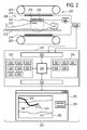
- Fig. 2 illustrates a medical apparatus 200 according to an embodiment of the invention.
- the medical apparatus 200 comprises a magnetic resonance imaging system 202.
- the magnetic resonance imaging system 202 comprises a magnet 204.
- the magnet 204 is a so-called open magnet which uses toroidal magnets above a subject 210.
- the open magnet has a large open space 206 and an imaging zone 208 in the center. It is advantageous to use an open magnet 204 because it gives more space for a physician to articulate or move a catheter 222.
- a subject 210 is within the open space 206 and lying partially within the imaging zone 208.
- the subject 210 is reposing on a subject support 212. Inside the open space 206 there are also gradient coils 214.
- the gradient coils 214 are connected to a gradient coil power supply 216. Adjacent to the subject 210 and the imaging zone 208 there is a radio-frequency coil 218. The radio-frequency coil 218 is connected to a transceiver 220. A catheter 222 has been inserted into the subject 210. The tip of the catheter 222 is within the imaging zone 208. The transceiver 220 and the gradient coil power supply 216 are connected to a hardware interface 226 of a computer 224.
- the computer further comprises a processor 228 which uses the hardware interface 226 to control and operate the magnetic resonance imaging system 202.
- the computer system further comprises a user interface 230, computer storage 232, and computer memory 234 all of which are connected to and controlled by the processor 228.
- the computer storage 232 is shown as containing a brachytherapy treatment plan 240.
- the brachytherapy treatment plan 240 comprises information descriptive of a plan for treating a treatment zone 274 within the subject 210.
- the brachytherapy treatment plan 240 may also comprise data which is descriptive of paths that a catheter 222 could take towards the treatment zone 274.
- the computer storage 232 is further shown as containing a pulse sequence 242.
- the pulse sequence 242 comprises instructions which enable the magnetic resonance imaging system 202 to acquire magnetic resonance data.
- the computer storage 232 is shown as further comprising or containing planning magnetic resonance data 244.
- the computer storage 232 is further shown as containing catheter placement positions 246.
- the computer storage 232 is further shown as containing catheter control commands 248.
- the catheter control commands 248 contain detailed instructions on the location and dwell times of radiation sources within the catheters in order to selectively treat a treatment zone 274.
- the computer storage 232 is further shown as containing guidance magnetic resonance data 250.
- the computer storage 232 is further shown as containing a magnetic resonance image 252 constructed from the guidance magnetic resonance data 250.
- the computer storage 232 is further shown as containing an image segmentation 254.
- the image segmentation may represent an image segmentation locating placed catheters and/or it may also represent an image segmentation 254 which identifies key elements of the subject's 210 anatomy which enable the calculation of the catheter placement positions 246. This may for instance include orifices and/or pathways through veins and arteries.
- the computer memory 234 is shown as containing a control module 260.
- the control module comprises computer executable code which enables the processor 228 to control the operation function of the medical apparatus 200.
- the control module 260 may use the pulse sequence 242 to acquire the planning magnetic resonance data 244 and/or the guidance magnetic resonance data 250.
- the computer memory 234 is shown as further containing an image reconstruction module 262.
- the image reconstruction module 262 may be used for reconstructing magnetic resonance images from the planning magnetic resonance data 244 and/or the guidance magnetic resonance data 250. For instance the image reconstruction module 262 may be used to reconstruct the magnetic resonance image 252 from the guidance magnetic resonance data 250.
- the computer memory 234 is further shown as containing an image segmentation module 264.
- the image segmentation module may be used for segmenting magnetic resonance images 252 for identifying key anatomical locations within the subject 210 and also for identifying the locations of catheters 222 that have been placed.
- the image segmentation module 264 may also be used for identifying fiduciary markers located on the subject 210 and/or the catheters 222. For instance a catheter may have a fiduciary mark which enables the identification of the location and orientation of the catheter. In some embodiments a radioactive source may also have a fiduciary mark which may be identified by the image segmentation module 264.
- the computer memory 234 is further shown as containing a catheter placement and control command generation module 266.
- the catheter placement and control command generation module 266 contains computer executable code which may use the brachytherapy treatment plan 240, the planning magnetic resonance data 244, the guidance magnetic resonance data 250, and/or the magnetic resonance image 252 to generate the catheter placement positions 246 and/or the catheter control commands 248.
- the computer memory 234 is further shown as containing a graphical user interface driver module 268.
- the graphical user interface driver module 268 is configured for driving a graphical user interface 270.
- the graphical user interface 270 is shown as being operated by the user interface 230. For instance the graphical user interface 270 may be displayed on a computer monitor, display or tablet computer.
- the graphical user interface 270 displays a magnetic resonance image 252. Within the magnetic resonance image 252 a subject 210 with a catheter inserted 222 is shown. A catheter placement position 246 is superimposed on the subject 210. A treatment zone 274 is also superimposed on the image of the subject 210.
- a physician or other healthcare provider may use the displayed catheter placement position 246 as a guide to where to place the catheter 222. It should be noted in this image that the catheter 222 is not placed exactly where the catheter placement position 246 is located.
- the physician or healthcare provider may click the catheter inserted button 278. This sends a catheter inserted signal from the user interface 230 to the processor 228.
- the processor 228 may then segment the image 252 and identify the location of the catheter 222.
- the processor 228 may then if the catheter is outside of a predetermined distance from the catheter placement position 246 recalculate the remaining catheter placement positions 246 and recalculate all of the catheter control commands 248.
- Fig. 3 shows an embodiment of a medical apparatus 300 according to an embodiment of the invention.
- the embodiment shown in Fig. 3 is similar to that shown in Fig. 2 .
- the catheter 222 is intended to possibly represent multiple catheters inserted in the subject 210.
- the catheter actuator 302 is configured for controlling the position of a radioactive brachytherapy source within each of the catheters 222 as a function of time.
- the processor 228 executes the control module 260.
- the control module 260 uses the catheter control commands 248 to control the catheter actuator 302. In this way the medical apparatus 300 can perform an automated radiotherapy of the subject 210.
- the medical apparatus only comprises the catheter actuator 302.
- the magnetic resonance imaging system 202 and the catheter actuator 302 are located at separate positions.
- the catheters may be inserted while the subject 210 is within the magnetic resonance imaging system 202.
- the subject 210 may then be moved to a separate location where the radioactive sources are inserted into the catheters 222 and then are connected to the catheter actuator for actuation.
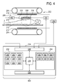
- Fig. 4 shows a medical apparatus 400 according to a further embodiment of the invention.
- the medical apparatus 400 is similar to that shown in Figs. 2 and 3 .
- the embodiment shown in Fig. 4 shows a catheter location verification system 402.
- the catheter location verification system 402 is connected to two or more catheters 222.
- the catheter location verification system 402 is connected to the hardware interface 226.
- the catheter location verification system 402 uses a sensor or sensors to determine the absolute or relative position of catheters 222 with respect to each other. This may be useful in determining if the catheters 222 have moved in between treatment sessions. For instance shape-sensing fiber optics and/or piezoelectric transducers at the tips of the catheters 222 may be used.
- the computer storage 232 is shown as containing a measured catheter position 404. These may be absolute locations or they may be sensor readings taken from the catheters 222 by the catheter location verification system 402.
- the computer memory is further shown as containing a catheter location verification system driver 406.
- the catheter location verification system driver 406 contains computer executable code which enables the processor 228 to control the catheter location verification system 402 and acquire the measured catheter position 404.
- the feature shown in Figs. 3 and 4 may be combined.
- the magnetic resonance imaging system 202 is not present. That is to say the catheter location verification system 402 may stand alone. This may be useful in some situations for instance a catheter location verification system 402 may be used to take the measured catheter position 404 immediately after the catheters 222 are inserted into the subject 210 while the subject 210 is still within the magnetic resonance imaging system 202 and has not been moved.
- the subject 210 may then be moved to a different location for performing a brachytherapy treatment session. Before the brachytherapy is performed the subject 210 may be connected to a different catheter location verification system 402 or the same one moved to the same location. This may be used to verify the catheter locations before the beginning of a therapy.
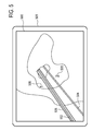
- Fig. 5 shows a drawing of a magnetic resonance image 500 that could be displayed in a graphical user interface 501 of a medical apparatus according to an embodiment of the invention.
- Superimposed on this magnetic resonance image 500 is a first catheter placement position 502 and a second catheter placement position 504.
- the physician or healthcare provider may use these two positions 502, 504 as a guide for inserting a catheter 506.
- the physician or healthcare provider may insert a second catheter along the second catheter placement position 504.
- Fig. 5 illustrates a possible way to display catheter information on top of real time images during an intervention.
- the intervention list may insert catheter 506 along first catheter placement position 502.
- the second catheter placement position 504 is displayed on the image 500 although the second catheter has not yet been inserted.
- the graphical user interface could also show some additional information like identification numbers 508 to identify the different catheters.
- Embodiments of the invention may provide for a procedure for optimized placement of catheters used for high dose rate brachytherapy using magnetic resonance imaging guidance. This may include the use of a computer algorithm to find the optimal catheter arrangement, a method to assist the interventionalist in inserting the catheters at the optimum positions, and a method to verify the positioning at a later time.
- embodiments may provide for conventional treatment planning algorithms with a simplified algorithm, using only a limited number of reference points for dose calculations. Such a calculation is sufficiently fast and flexible to find a good initial guess for catheter positions and to quickly determine small corrections during the intervention.
- the placement of brachytherapy catheters can be improved significantly compared to conventional procedures.
- verification of catheter positions may be independent of medical imaging modalities. In this way it is possible to verify the catheter position directly before the start of the treatment session without the need of moving the patient.
- the invention proposes a scheme for quick and easy verification of the catheter positions before the start of the treatment session without the need for medical imaging modalities, while the patient can remain in the same position for catheter verification and treatment.
- Embodiment of the invention may provide for extensions of the MRI system that include in-room displays, controls and a application-specific software solution incl. data linkage to the therapy planning module and image databases.
- Embodiment of the invention may provide for optimized treatment planning before the intervention.
- An existing treatment planning algorithm e.g. inverse planning by simulated annealing
- a broader parameter range in order to optimize not only the dwell properties within the catheters, but also the positions of the catheters themselves. This can be realized in the following way:
- Embodiment of the invention may provide for an interventional magnetic resonance system envisaged for the described procedures already includes a display showing real-time MR images to the interventionalist. This display must be extended to visualize the following information:
- Embodiment of the invention may have the feature that catheter positions are calculated with respect to a planning image acquired before the intervention.
- coordinates of the planning image must be mapped to the real-time images. If the organs under consideration do not move significantly during the intervention, the system can use a fixed coordinate frame which is defined once before the interventions by specifying one or more points in space and relating them to points in the planning images. If motion of the organs cannot be excluded (e.g. respiratory motion), there are several options:
- Embodiment of the invention may provide for magnetic resonance imaging sequences that are used to optimally support the workflow including planning, real-time guidance, and verification of the procedure or parts of it.
- the target lesions and structures and organs at risk are important.
- a set of scans will be required: DCE for imaging of the organ and the tumor(s), T1W-3D-TFE for overall display of anatomy including surrounding organs.
- Diffusion- and T2W-weighted imaging for further specification of the tumors, are just very likely examples. Also Diffusion and T2 quantification may become relevant future methods.
- imaging will be typically performed in one or several interleaved 2D imaging stacks.
- Using several interleaved imaging stacks is advantageous for tumors in moving organs such as liver or deformable organs as breast.
- a coronal view will be used to continuously monitor the position of the lesion during respiration.
- the paracoronal view will be chosen such to additionally contain the planned needle axis while a paratransverse view can be added to immediately detect out-of-plane needle advancement in both imaging planes.
- the multi-stack approach has advantages in cases where ultimate accuracy is required, such as for small lesions (e.g. mamma).
- multiple imaging stack sequences benefit from appropriate display of the data:
- two orthogonal stacks planned to contain the needle can be displayed in 3D to additionally immediately visualize the section line and thus the planned needle path in 3D as well.
- Stacks can also be measured at the same geometry but, as mentioned, with different content or, technically more advanced, even different types of contrast and sequences (T1W, T2W, T1/T2W, IR, 2D, 3D).
- Such techniques will be valuable for applications requiring more sophisticated methods for tumor characterization (e.g. prostate).
- tumor characterization e.g. prostate
- For such data overlay techniques may apply to optimally represent the data.
- Verification scans will typically be performed to confirm and assess intermediate and final results of the procedure.
- One example is to measure the proper placement of devices such as needles, catheters or guide-wires.
- Such scans could be automatically planned and performed such that an optimal assessment is possible, e.g. by preparing a set of images to optimally visualize the tip of the device in a given respiratory state while immediately afterwards performing a set of images, (partly) guided by the prior information, to visualize the target lesion or adjacent organs/structures (at risk) in the same respiratory state with high relative accuracy to the previous scan.
- the information from the verifications scans or from additionally, subsequently acquired images are immediately ideally suited to be fed into the on-line therapy planning module (device positions, target lesion update (swelling may have occured), update organs at risk (again swelling may have occured).
- targeted complication detection scans can be included using above-measured parameters. E.g. if a certain probability for bleeding in a neighbor organ or near a critical vessel along the needle path is deduced, a respective scan could be recommended or automatically performed.
- a method is provided where once a needle is in place, the interventionalist is able to instruct the computer to perform an online optimization, to visualize the next needle path to be followed and to make according adjustments for the subsequent MRI scans.
- the computer first needs to determine the actual catheter position. This can be realized by analyzing the acquired real-time images or by using markers on the catheters. It is then in principle possible to use the same optimization procedure as in the initial planning before the intervention, keeping the already placed catheters fixed. Even with today's computer hardware, such an optimization procedure may very well take several minutes or more, which increases the time needed for the whole intervention significantly.
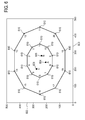
- Fig. 6 shows a brachytherapy treatment plan according to an embodiment of the invention.
- the x-axis labeled 600 is a first directional dimension in arbitrary units.
- the y-axis labeled 602 is a second directional dimension in arbitrary units.
- Within the center there is the location of a first brachytherapy radiation source 604, a second brachytherapy radiation source 606, and a third brachytherapy radiation source 608.
- Surrounding these locations for the radiation sources 604, 606, 608 are 20 reference points 610.
- the reference points 610 may for instance be anatomical locations within a subject.
- Fig. 7 illustrates how the brachytherapy treatment plan can be changed by a misplaced catheter.
- the reference points 610 are identical to that shown in Fig. 6 .
- the original placements of the radiation sources 604, 606 and 608 are shown.
- the actual placement is shown as position 704.
- the second brachytherapy radiation source is repositioned at location 706 and the third brachytherapy radiation source is relocated to position 708.
- Fig. 8 illustrates the advantage of shifting the locations of the second 706 and third 708 brachytherapy radiation sources in response to the misplacement of the first brachytherapy radiation source 704.
- the x-axis labeled 800 shows the dose air 802 for each of the reference points 800.
- the curve labeled 804 shows the deviations of the dose deposited at the reference point after the misplacement of a relative to the initial planning without any correction.
- the curve labeled 806 shows only correction of the optimized dwell times. That is to say the locations 606 and 608 are used.
- the curve labeled 808 shows the effect of correcting both the dwell times and using the corrected positions 706 and 708.
- This implementation of an optimization algorithm can easily be extended to allow for weighting of the reference points or for restrictions on the possible motion of the dwell positions (e.g. only along catheter tubes).
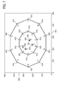
- Fig. 9 shows a different example of a brachytherapy treatment plan. This is similar to that shown in Fig. 6 except a first catheter placement position 900 is shown and a second catheter placement position 902 is shown. Along each of these catheter placement positions 900, 902 are dwell locations for brachytherapy radiation sources. Along the first catheter placement position 900 there are four dwell locations of a first radiation source 904. Along the second catheter placement position 902 there are four dwell locations 906 of a second radiation source 906. The radius of the dwell locations 904, 906 is an indication of the relative length of the dwell time.
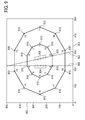
- Fig. 10 is identical to that of Fig. 9 except in Fig. 10 a first catheter has been inserted, but is misaligned. Line labeled 1000 and the five points on this line indicate the five misaligned dwell locations.
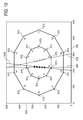
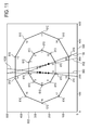
- Fig. 11 illustrates how a method can be used to compensate for the misaligned catheter 1000.
- Fig. 11 is identical to Fig. 10 except an online optimization has been performed to find a modified position for the second catheter 1100.
- the dwell times have also been recalculated. The time at several dwell points has been increased and others have been decreased for both catheters 1000, 1100.
- Fig. 12 is similar to Fig. 8 in that it shows the benefit of applying the method to a situation illustrated by Figs. 9-11 .
- the relative dose air 802 is shown for each of the reference points labeled 1-20 800.
- the curve labeled 1204 shows the effect of using catheter positions 1000 and 902 without correcting the dwell times.
- the curve labeled 1206 shows the effect of correcting only the dwell times.
- curve 1208 shows the effect of correcting the dwell times and using the catheter positions 1000 and 1100. It can be seen that using both corrections as shown in 1208 reduce the dose relative air. If a treatment plan is to be followed over two or more treatment sessions, it is vital that catheters do not move between the sessions.
- Fig. 13 illustrates the functioning of a catheter location verification system according to an embodiment of the invention.
- a tumor volume 1302 is surrounded by healthy tissue 1300.
- Three catheters 1304 have been inserted through the healthy tissue 1300 into the tumor volume 1302.
- a piezoceramic transducer 1306 At the tip of each catheter 1304 is a piezoceramic transducer 1306.
- the piezoceramic transducer is adapted for both sending and receiving ultrasonic signals.
- each catheter 1304 can emit a piezoelectric signal and the other two remaining catheters 1304 can receive the signal.
- the delay between the sending and the receiving of the ultrasonic signal or the phase difference of transmitted and received signal may be used to determine a relative distance between each of the tips. Using this method three different distances may be established.
- the catheter tip positions are measured using small piezoelectric elements introduced into or integrated with the catheters and connected to the outside via a thin MR-compatible cable along the catheter tube.
- the relative distance between any two tips can now be determined by measuring the sound propagation time in the tumor volume.
- An ultrasound wave is emitted by one of the piezoelectric transducers and received by all the other transducers.
- An external electronic circuit measures the time between emission and reception of the signal or the phase difference of the emitted and received signals. Then the next catheter is used as transmitter and so forth. In this way a complete matrix of sound propagation delays, i.e., distances between the catheter tips is determined.
- measuring the phase shift of a sine wave is probably more reliable than measuring the pulse propagation time.
- Such a measurement can be taken over many oscillation periods to increase accuracy and a lock-in detector technique can be used to measure even very small signal amplitudes. Assuming an ultrasound frequency of 100 kHz, the wavelength in water is approximately 15 mm. Relative spatial shifts of the catheters in the mm range can thus easily be detected.
- the positions of the catheters can be verified using small piezoelectric elements are positioned at the tip of the catheters. In another embodiment they are integrated with the catheters at the catheter tips. In this, case an MR-compatible wiring along the catheter allows the transducers to be contacted from the outside without compromising MR safety.
- the piezo transducers emit an ultrasound wave which is received by all other transducers. The propagation time of the sound (or the phase difference between emitted and received signals) is measured. In this way, the distances between any two catheter tips can be determined very precisely.
- a first reference measurement of the distances is taken directly after the insertion of the catheters, ideally while the patient is still under real-time MR observance, to make sure that the positions are correct.
- the relative positions of the catheter tips are verified by comparing a distance measurement to the initially taken values.
- the method for catheter position verification disclosed here relies on miniature piezoceramic ultrasound transducers. Similar, however much more sophisticated, devices are already available for medical applications; they are currently used for intravascular ultrasound imaging (IVUS) and intracardiac imaging. Hollow sphere transducers seem to be particularly well suited for the application described here because of their spherically symmetric radiation pattern. This type of piezoceramics has also been proposed for medical applications, such as high-intensity ultrasound exposimetry and tissue ablation.
- Real-time catheter position measurement can be employed to move the patient into the correct position, such that the catheters are well aligned. Additional information about the motion of organs (e.g., simulation of bladder filling/emptying) can be included in the determination of catheter misalignment.
- the pre-interventional planning software suggests not only the optimum, but a number of good solutions for catheter placement. Since the constraints for catheter placement are sometimes difficult to define, it may be easier and less time-consuming for the physician to choose one out of a few good suggestions, instead of trying to adapt the constraint definitions.
- the HDR treatment is performed using miniature X-ray sources instead of radioactive sources (like the ones manufactured by Xoft Inc.).
- the complete treatment process could be carried out during real-time MR imaging to verify the exact position of the seed within the catheters.
- One embodiment of the catheter position verification based on sound propagation employs additional piezoelectric elements attached to the side of the catheters. In this way not only the tip positions but the also the angular arrangement of the catheters can be verified.
- the ultrasound transducers are not fixed to the catheter tips but can be temporarily inserted from the outside, similar to the radioactive seeds.
- the sound transducers are shifted right through the open tip of the catheters in order to ensure a good of the emitted sound to the tissue.
- a mechanical stop at the catheter tip ensures reproducible alignment of the transducers.
- movable ultrasound transducers are inserted in the catheters and distance measurements are performed continuously or stepwise while pulling the transducers along the catheters at constant speed (this can be ensured by a mechanical connection of wires pulling the transducers). In this way not only the tip position, but the complete catheter path can be verified, provided that a sufficiently localized coupling of the sound to the surrounding tissue is possible.
- One embodiment includes a stiff mechanical connection of the distal ends of the catheters outside the body. Combined with the distance measurement of the tips this measure ensures correct angulation of the catheters.
- One embodiment of the catheter placement verification employs an optical shape sensing device, i.e. an optical fiber using reflectometry to determine its own shape and position.
- an optical shape sensing device i.e. an optical fiber using reflectometry to determine its own shape and position.
- a shape-sensitive fiber can be inserted into the catheters one after the other to precisely determine the position of the catheter tip and the bending of the catheter. If the distal ends of all catheters are rigidly connected, the relative position of all catheters can be determined in this way.
- shape-sensing optical fibers are permanent parts of the catheters.
- the fibers can be used for real-time position determination during the intervention.
- mapping of the planning image and the real-time images is performed manually by the interventionalist.
- the proposed needle path is displayed on the planning image only.
- the physician uses this information to steer the needle in the real-time images.
- the physician determines deviations from the proposed needle path by comparing the images and marks the actual needle position on the planning image.
- the software uses this information to calculate the optimization suggestions. This may be the method of choice if automatic image mapping is impossible because of motion or lack of structure in the image.
- the dynamics of respiratory motion is taken into account for automatic mapping of the planning image and the real-time images. This requires the acquisition of additional information about the motion. This can be achieved using external breathing state measurement devices or shape-sensing fibers fixed to the catheters.
- shape-sensing fibers permanently attached to the catheters are used to determine the motion and position of the catheters in real time during the treatment session.
- An additional real-time optimization algorithm can be employed to induce slight variations of the position of the seed during application in order to compensate for motion of critical organs with respect to the seed due to breathing.
- the dose deviations are expressed as quotients instead of differences: min ⁇ ⁇ i 1 - d i 1 d i 0 2
- Another embodiment of the algorithm takes additional boundary conditions for the allowed doses, expressed in terms of inequalities, into account.
- the invention can be used according to an examplary method as follows:
- Cancer treatment using brachytherapy involves the insertion of the radioactive source seeds into a target region (i.e. tumor). Precise application of the radiation dose is an essential requirement to destroy the malignant while sparing healthy tissue.
- a target region i.e. tumor
- Precise application of the radiation dose is an essential requirement to destroy the malignant while sparing healthy tissue.
- Currently used seeds possess a rotation-symmetric design and consequently a roughly radial-symmetric radiation/dose distribution. Due to the proximity of target regions and organs at risk a local and properly directed irradiation is essential. The proposed design allows irradiating the target while "shielding" organs at risk and results in a significantly improved dose distribution.
- the radiation sources are not rotation-symmetric in design and allow a conformal (adapted anisotropic) dose distribution.
- a workflow according to an embodiment of the invention includes a combination of image-based dose and source placement planning as well as angular applicator control/image guidance during insertion. This approach may allow a higher placement accuracy with locally increased dose, reduced irradiation of organs at risk enabling reduced adverse side-effects, improved cure-rates and a more efficient clinical workflow.
- Brachytherapy involves placing numerous radiation sources (seeds) into a target region (tumor). Depending on the appropriateness criteria low, medium or high dose brachy-therapy can be used for treatment (Low Dose Rate (LDR), Medium Dose Rate (MDR), High Dose Rate (HDR)).
- LDR Low Dose Rate
- MDR Medium Dose Rate
- HDR High Dose Rate
- HDR high-radial radiation
- a computer-controlled machine pushes a single highly radioactive seed into previously placed catheters or needles one by one for a variable (dose planned) duration.
- HDR is normally applied in several treatment sessions over 2-5 consecutive days (HDR mono-therapy) instead of more highly fractionated application of typically 5-7 weeks for external beam radiation, or it is used as an add-on to shorten the external beam radiation protocol in combination therapy.
- Success of these types of procedures may require accurate dose delivery to a target volume according to a pre-procedural plan, and this is confounded by inaccurate placement and/or dwell times of the brachytherapy seeds.
- Fig. 14 illustrates why it may be beneficial to use a brachytherapy radiation source with an anisotropic radiation source.
- Region 1400 is a targeted region.
- the targeted region 1400 may for instance represent a tumor.
- Region 1402 below region 1400 is identified as an organ or a region at risk. For instance this may be an organ which would not be beneficial to irradiate at the same time that the targeted region 1400 is eradiated.
- 1404 shows an access path between the targeted region 1400 and the organ at risk 1402.
- the access path 1404 for instance may be provided by a brachytherapy catheter.
- the point 1406 illustrates the location of an isotropic radiation source.
- the isotropic radiation source 1406 produces an isotropic radiation field 1408.
- the production of an isotropic radiation field 1408 is not beneficial because both the target region 1400 and the organ at risk 1402 are eradiated. Therefore it may be beneficial to have a radiation source which is anisotropic so that radiation may be preferentially directed into the target region 1400 and not into the organ at risk 1402.
- the current radial symmetric design of sources limits the degree of freedom in dose distribution significantly. Since the number of feasible access paths 1404 for seed placement 1406 is often anatomically limited and the boundary surfaces between target region and surrounding tissue can be very close, the dose distribution 1408 of currently employed seeds is not always adequate. If the seed is centered at the boundary of target 1400 and organ at risk 1402 the boundary of the target is treated well but the organ at risk gets a too high dose. If the access path is vertically moved up to spare the organ at risk only a low dose reaches the outer rim of the target. This restriction by design leads to an undesirable compromise between radical treatment and sparing of organs at risk.
- the dose distribution of seeds as used today may be radially quite nonuniform. This variation between different seeds adds an additional uncertainty about the true applied dose distribution.
- Radiation sources according to some embodiments of the invention have a non-rotational-symmetric dose distribution by design allowing an anisotropic radiation pattern. Via selecting seeds with appropriate irradiation angles and controlled angulation/rotation of the radiation source an improved conformal dose distribution can be obtained.
- Fig. 15 shows an example of an anisotropic radiation source for brachytherapy according to an embodiment of the invention.
- a radioactive seed 1500 and a cross-sectional axial view of the same radioactive seed shown.
- On the top half there is a radioactive substance 1504 with the bottom hemisphere being comprised of a shield material 1506.
- An unshielded region or material 1508 covers the radioactive substance 1504.
- the use of the shield material 1506 causes an anisotropic radiation distribution around the radioactive seed 1500, 1502.
- There is a seed control wire 1510 which allows the radioactive seed 1500, 1502 to be inserted into a brachytherapy catheter and also to be rotated. Rotating the radioactive seed allows control of the anisotropic radiation field that it generates.
- Fig. 16 shows another embodiment of an anisotropic radiation source according to an embodiment of the invention. Again there is a cross-sectional side view 1600 and a cross-section axial view 1602 of the radioactive seed or source. The embodiment shown in Fig. 16 is similar to that of Fig. 15 except along the axial direction the radioactive substance 1504 is shorter. This causes an axially shortened irradiation field.
- Fig. 17 shows a further embodiment of an anisotropic radiation source according to an embodiment of the invention. This embodiment is similar to the embodiment shown in Figs. 15 and 16 except in this case the radioactive material is smaller and further away from the access of the seed control wire 1510. This causes a radially focused irradiation field.
- Fig. 18 shows a further embodiment of an anisotropic radiation source according to an embodiment of the invention.
- the radioactive material is treated such that it creates an axially homogenized irradiation field. At different positions along the axial direction there are different amounts of radioactive material.
- Figs. 15 to 18 various radiation seeds are illustrated. Considering the access path situation from figure 14 it is clear that the anisotropic dose distribution allows higher doses for the target region while "shielding" the organs at risk when being inserted with the shield pointing downwards.
- Nucleotides 1504 may be used for constructing anisotropic radiation sources, some examples are, but not limited to: Radionuclide Type Half-life Energy Caesium-137 ( 137 Cs) ⁇ -ray 30.17 years 0.662 MeV Cobalt-60 ( 60 Co) ⁇ -rays 5.26 years 1.17, 1.33 MeV Iridium-192 ( 192 Ir) ⁇ -particles 73.8 days 0.38 MeV (mean) Iodine-125 ( 125 I) ⁇ -rays 59.6 days 27.4, 31.4 and 35.5 keV Palladium-103 ( 103 Pd) ⁇ -ray 17.0 days 21 keV (mean) Ruthenium-106 ( 106 Ru) ⁇ - -particles 1.02 years 3.54 MeV
- Examples of possible shield materials 1506 are, but not limited to: Lead, Barium sulfate, and Steel.
- a directional marking is essential.
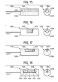
- Figs. 19, 20, and 21 some possible embodiments of respective seed shell designs are shown.
- Fig. 19 shows a side view 1900 and an axial view 1902 of a radioactive seed according to a further embodiment of the invention.
- the radioactive seed in Fig. 19 is an anisotropic radiation field. So that it can be understood in which direction the field is produced there is a notch 1904 on the end of the radioactive seed or source.
- Fig. 20 shows a further embodiment of a radioactive seed or source according to an embodiment of the invention.
- a side view 2000 and an axial view 2002 shown.
- a pattern 2004 or a painted surface is used to indicate the axial asymmetry of the radioactive seed.
- Fig. 21 shows a further embodiment of a radioactive seed or source according to an embodiment of the invention.
- a side view 2100 and an axial view 2102 is shown.
- the embodiments shown in Figs. 19-21 enable the determination of the direction of the anisotropic radiation field.
- a fiduciary marker may be mounted on the radiation shield so that the direction or orientation of the radioactive seed may be determined using magnetic resonance imaging.
- the angular surface coloring and grooves principle can also be extended to a more advanced pattern (i.e. bar code) to identify the seed type along with its orientation. Similar orientation/identification designs could also be placed on the attached seed control wire to simplify the design of the source itself.
- imaging marker into the design. This feature would allow real-time tracking and validation of the marker position/orientation.
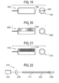
- FIG. 22 shows a brachytherapy catheter 2200 according to an embodiment of the invention.
- the brachytherapy catheter comprises a seed guide 2202.
- the seed guide is the catheter tube inserted into a subject.
- a radioactive seed or source 2204 connected to a seed control wire 1510.
- This wire 1510 enables the radioactive seed 2204 to be inserted or removed from the seed guide 2202. Further it also enables the rotational orientation of the radioactive seed 2204 to be controlled.
- the position and rotational orientation of the radioactive seed 2204 within the seed guide 2202 can be controlled as a function of time.
- the seed control wire 1510 is connected to an axial position sensing movement and control device 2206 and a radial position sensing and rotational control device 2208. This enables the radioactive seed 2204 to be rotated and also to be moved in and out of the seed guide tube 2202. In an alternative embodiment the radial position sensing and rotational control device 2208 is absent. This would be useful for instance when the radioactive seed 2204 produces an isotropic radiation field. Such a brachytherapy catheter 2202 could also be controlled manually.
- the seed control wire 1510 could have a device which controls its depth and also an indicator which indicates the rotational orientation of the radioactive seed 2204.
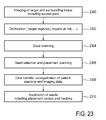
- Fig. 23 shows an exemplary application method.
- dose planning is performed.
- radioactive seed selection and placement planning is performed. Radioactive seeds of different strengths and types of radioactive seeds may be selected. For instance seeds which produce isotropic radiation fields and/or seeds which produce anisotropic radiation fields may be selected.
- Next in step 2308 there is data transfer co-registration of the patient and machine and image data is performed.
- the seeds are applied to the subject. This includes placement control and tracking of the radioactive seeds.
- magnetic resonance imaging may be used to track the location of the radioactive seeds and/or determine their rotational orientation.
- the steps in Fig. 1 may be combined with those steps shown in Fig. 23 .
- the steps in Fig. 23 are particularly oriented towards use of a radioactive seed with an anisotropic radiation source.
- the method shown in Fig. 23 may be performed independently of the steps shown in Fig. 1 .
- a workflow as shown in figure 23 is suggested. First imaging of the target region(s) is done. Based on this data delineation of target and organs at risk or other structures which are relevant for dose planning is performed. Thereafter, dose planning, taking into account the additional degrees of freedom provided by anisotropic dose patterns, can be carried out. The calculated result provides information about the placement including rotation of the respective seed types and their application duration. During the intervention this data is spatially co-registered with the patient space and the applicator device which then places the seeds according to the planning data.
- control of the precise localization and orientation can be done differently.
- applicator type e.g. rigid needles or flexible catheters
- the precise placement can be monitored using real-time imaging (e.g.US, MR). This would also allow a more advanced workflow which involves a potential real-time re-planning of seed placement depending on the respective true applicator and organ positions. This tracking could also be achieved using shape sensing applicator tubes.
- Applicator shape and therefore trajectory information can also be obtained from image data acquired after applicator but before seed placement (magnetic resonance imaging, computed tomography, ultrasound, and X-ray). Given the shape of the applicator using any of the above methods, the orientation of the seed can be calculated depending on the orientation of the proximal end of the seed control wire by means of a mechanical model of the seed control wire.
- the seeds are made of oval (or any other non-radially symmetric) shape to prevent rotation of the seed after placement, which may otherwise occur due to physiological motion.
- the seeds may be equipped with hooks, hinges that fixate to the tissue upon release from the needle / catheter.
- a computer program may be stored/distributed on a suitable medium, such as an optical storage medium or a solid-state medium supplied together with or as part of other hardware, but may also be distributed in other forms, such as via the Internet or other wired or wireless telecommunication systems. Any reference signs in the claims should not be construed as limiting the scope.
Applications Claiming Priority (2)
| Application Number | Priority Date | Filing Date | Title |
|---|---|---|---|
| US201161548356P | 2011-10-18 | 2011-10-18 | |
| PCT/IB2012/055093 WO2013057609A1 (en) | 2011-10-18 | 2012-09-25 | Medical apparatus for displaying the catheter placement position |
Publications (2)
| Publication Number | Publication Date |
|---|---|
| EP2744567A1 EP2744567A1 (en) | 2014-06-25 |
| EP2744567B1 true EP2744567B1 (en) | 2015-04-29 |
Family
ID=47178234
Family Applications (1)
| Application Number | Title | Priority Date | Filing Date |
|---|---|---|---|
| EP12784697.0A Not-in-force EP2744567B1 (en) | 2011-10-18 | 2012-09-25 | Medical apparatus for displaying the catheter placement position |
Country Status (5)
| Country | Link |
|---|---|
| US (1) | US10245447B2 (zh) |
| EP (1) | EP2744567B1 (zh) |
| CN (1) | CN103889507B (zh) |
| IN (1) | IN2014CN02548A (zh) |
| WO (1) | WO2013057609A1 (zh) |
Families Citing this family (23)
| Publication number | Priority date | Publication date | Assignee | Title |
|---|---|---|---|---|
| WO2016049297A1 (en) * | 2014-09-24 | 2016-03-31 | Imricor Medical Systems, Inc. | Steerable sheath including elastomeric member |
| US9821143B2 (en) | 2011-12-15 | 2017-11-21 | Imricor Medical Systems, Inc. | Steerable sheath including elastomeric member |
| US9757538B2 (en) | 2011-12-15 | 2017-09-12 | Imricor Medical Systems, Inc. | MRI compatible control handle for steerable sheath with audible, tactile and/or visual means |
| JP6106259B2 (ja) * | 2012-03-21 | 2017-03-29 | コーニンクレッカ フィリップス エヌ ヴェKoninklijke Philips N.V. | 医用イメージングと生検データとを統合する臨床ワークステーション及びこれを使用する方法 |
| NL2010838C2 (en) * | 2013-05-22 | 2014-11-26 | Nucletron Operations Bv | An afterloading device, and use thereof. |
| WO2014194959A1 (en) * | 2013-06-06 | 2014-12-11 | Universität Duisburg-Essen | Device for collimating electromagnetic radiation |
| WO2014207622A1 (en) * | 2013-06-28 | 2014-12-31 | Koninklijke Philips N.V. | Ultrasound-guided adaptive brachytherapy |
| CN105792894B (zh) * | 2013-09-30 | 2019-12-24 | 皇家飞利浦有限公司 | 用于外部射束放射治疗和短程治疗的医学仪器 |
| CN106030657B (zh) * | 2014-02-19 | 2019-06-28 | 皇家飞利浦有限公司 | 医学4d成像中的运动自适应可视化 |
| US9877697B2 (en) * | 2014-04-30 | 2018-01-30 | Emory University | Systems, methods and computer readable storage media storing instructions for generating planning images based on HDR applicators |
| EP3140006B1 (en) * | 2014-05-06 | 2017-09-13 | Koninklijke Philips N.V. | Treatment planning system |
| US10945793B2 (en) * | 2014-05-09 | 2021-03-16 | Edda Technology, Inc. | System and methods for percutaneous treatment planning and treatment monitoring |
| JP6894839B2 (ja) * | 2014-10-17 | 2021-06-30 | コーニンクレッカ フィリップス エヌ ヴェKoninklijke Philips N.V. | 介入治療内で器具を挿入する間の実時間の臓器区分化及び器具ナビゲーションのためのシステム、並びにその作動方法 |
| WO2016131637A1 (en) | 2015-02-20 | 2016-08-25 | Koninklijke Philips N.V. | Medical system, apparatus and method for shape sensing |
| US10933254B2 (en) | 2015-09-01 | 2021-03-02 | Koninklijke Philips N.V. | Device and method for assisting in a brachytherapy procedure |
| US10729917B2 (en) * | 2016-03-24 | 2020-08-04 | Koninklijke Philips N.V. | Treatment assessment device |
| EP3532163B1 (en) * | 2016-10-28 | 2020-04-15 | Koninklijke Philips N.V. | Graphical user interface for iterative treatment planning |
| EP3381512A1 (en) * | 2017-03-30 | 2018-10-03 | Koninklijke Philips N.V. | Determining at least one final two-dimensional image for visualizing an object of interest in a three-dimensional ultrasound volume |
| EP3547323A1 (en) * | 2018-03-30 | 2019-10-02 | Koninklijke Philips N.V. | Brachytherapy treatment planning system |
| EP3645115B1 (en) * | 2018-06-25 | 2021-05-12 | Mirion Technologies (Canberra), Inc. | Apparatus for visualizing a movable radiation source |
| EP3756729A1 (en) * | 2019-06-24 | 2020-12-30 | Koninklijke Philips N.V. | Configurable radiotherapy couch top for magnetic resonance radiotherapy simulation |
| DE102020102213A1 (de) | 2020-01-30 | 2021-08-05 | Carl Zeiss Meditec Ag | Verfahren zur Vorbereitung einer Brachytherapie, Brachytherapieverfahren und Brachytherapiesystem |
| FR3129601A1 (fr) * | 2021-12-01 | 2023-06-02 | Universite De Lille | Dispositif de chargement et de poussée de grains radioactifs |
Family Cites Families (16)
| Publication number | Priority date | Publication date | Assignee | Title |
|---|---|---|---|---|
| US5391139A (en) * | 1992-09-03 | 1995-02-21 | William Beaumont Hospital | Real time radiation treatment planning system |
| US6482142B1 (en) | 1997-07-24 | 2002-11-19 | Proxima Therapeutics, Inc. | Asymmetric radiation dosing apparatus and method |
| US6311084B1 (en) * | 1998-05-04 | 2001-10-30 | Robert A. Cormack | Radiation seed implant method and apparatus |
| US6217518B1 (en) * | 1998-10-01 | 2001-04-17 | Situs Corporation | Medical instrument sheath comprising a flexible ultrasound transducer |
| US6200255B1 (en) | 1998-10-30 | 2001-03-13 | University Of Rochester | Prostate implant planning engine for radiotherapy |
| US6725080B2 (en) | 2000-03-01 | 2004-04-20 | Surgical Navigation Technologies, Inc. | Multiple cannula image guided tool for image guided procedures |
| US6438401B1 (en) * | 2000-04-28 | 2002-08-20 | Alpha Intervention Technology, Inc. | Indentification and quantification of needle displacement departures from treatment plan |
| US6846282B1 (en) * | 2000-06-09 | 2005-01-25 | Varian Medical Systems, Inc. | Brachytherapy apparatus and methods |
| US6471632B1 (en) | 2001-05-18 | 2002-10-29 | Syntheon, Llc | Radioactive therapeutic seeds |
| ATE312648T1 (de) * | 2002-06-17 | 2005-12-15 | Nucletron Bv | System zur echtzeitplanung von strahlentherapie |
| WO2005115543A1 (en) | 2004-05-20 | 2005-12-08 | Wisconsin Alumni Research Foundation | Directionally emitting radioactive sources for brachytherapy |
| US7517310B2 (en) | 2005-11-18 | 2009-04-14 | Senorx, Inc. | Methods for tissue irradiation with shielding |
| EP2001367A4 (en) * | 2006-03-14 | 2010-11-24 | Univ Johns Hopkins | DEVICE FOR USING A MEDICAL DEVICE IN A BODY DURING A MEDICAL IMAGING METHOD AND CORRESPONDING DEVICE AND METHOD |
| US20080009658A1 (en) | 2006-06-19 | 2008-01-10 | Smith Peter C | Radiation therapy apparatus with selective shielding capability |
| US9844414B2 (en) * | 2009-08-31 | 2017-12-19 | Gregory S. Fischer | System and method for robotic surgical intervention in a magnetic resonance imager |
| US8398549B2 (en) * | 2010-02-16 | 2013-03-19 | Duke University | Ultrasound methods, systems and computer program products for imaging contrasting objects using combined images |
-
2012
- 2012-09-25 WO PCT/IB2012/055093 patent/WO2013057609A1/en active Application Filing
- 2012-09-25 CN CN201280051015.XA patent/CN103889507B/zh not_active Expired - Fee Related
- 2012-09-25 IN IN2548CHN2014 patent/IN2014CN02548A/en unknown
- 2012-09-25 EP EP12784697.0A patent/EP2744567B1/en not_active Not-in-force
- 2012-09-25 US US14/349,333 patent/US10245447B2/en not_active Expired - Fee Related
Also Published As
| Publication number | Publication date |
|---|---|
| WO2013057609A1 (en) | 2013-04-25 |
| CN103889507A (zh) | 2014-06-25 |
| EP2744567A1 (en) | 2014-06-25 |
| US10245447B2 (en) | 2019-04-02 |
| CN103889507B (zh) | 2016-09-21 |
| US20140303423A1 (en) | 2014-10-09 |
| IN2014CN02548A (zh) | 2015-07-31 |
Similar Documents
| Publication | Publication Date | Title |
|---|---|---|
| EP2744567B1 (en) | Medical apparatus for displaying the catheter placement position | |
| US10729917B2 (en) | Treatment assessment device | |
| EP2872913B1 (en) | Magnetic resonance guided linac | |
| JP5771219B2 (ja) | 形状検知による追跡を行うことを特徴とする小線源治療方法及び装置 | |
| EP3055024B1 (en) | Medical instrument for external beam radiotherapy and brachytherapy | |
| US11766298B2 (en) | Systems, methods, and devices for registering and tracking organs during interventional procedures | |
| US20140357977A1 (en) | Catheter Placement Detection System and Method for Surgical Procedures | |
| CN104994908A (zh) | 近距离放射治疗仪器、成像系统以及图像采集的方法 | |
| Cunha et al. | Toward adaptive stereotactic robotic brachytherapy for prostate cancer: demonstration of an adaptive workflow incorporating inverse planning and an MR stealth robot | |
| US20220265359A1 (en) | Determining ablation probe configuration | |
| JP2023521839A (ja) | アブレーション処置システム | |
| EP3038706B1 (en) | A system and method for visualizing information in a procedure of placing sources | |
| US20230090468A1 (en) | Systems, methods, and devices for registering and tracking organs during interventional procedures | |
| WO2014207622A1 (en) | Ultrasound-guided adaptive brachytherapy | |
| EP3429687B1 (en) | System for assisting in performing an interventional procedure |
Legal Events
| Date | Code | Title | Description |
|---|---|---|---|
| PUAI | Public reference made under article 153(3) epc to a published international application that has entered the european phase |
Free format text: ORIGINAL CODE: 0009012 |
|
| 17P | Request for examination filed |
Effective date: 20140320 |
|
| AK | Designated contracting states |
Kind code of ref document: A1 Designated state(s): AL AT BE BG CH CY CZ DE DK EE ES FI FR GB GR HR HU IE IS IT LI LT LU LV MC MK MT NL NO PL PT RO RS SE SI SK SM TR |
|
| 17Q | First examination report despatched |
Effective date: 20140728 |
|
| GRAP | Despatch of communication of intention to grant a patent |
Free format text: ORIGINAL CODE: EPIDOSNIGR1 |
|
| DAX | Request for extension of the european patent (deleted) | ||
| INTG | Intention to grant announced |
Effective date: 20141216 |
|
| RIN1 | Information on inventor provided before grant (corrected) |
Inventor name: KRUEGER, SASCHA Inventor name: KOKEN, PETER Inventor name: AMTHOR, THOMAS ERIK Inventor name: HOLTHUIZEN, RONALDUS FREDERIK JOHANNES Inventor name: WIRTZ, DANIEL Inventor name: UHLEMANN, FALK Inventor name: WEISS, STEFFEN |
|
| GRAS | Grant fee paid |
Free format text: ORIGINAL CODE: EPIDOSNIGR3 |
|
| GRAA | (expected) grant |
Free format text: ORIGINAL CODE: 0009210 |
|
| AK | Designated contracting states |
Kind code of ref document: B1 Designated state(s): AL AT BE BG CH CY CZ DE DK EE ES FI FR GB GR HR HU IE IS IT LI LT LU LV MC MK MT NL NO PL PT RO RS SE SI SK SM TR |
|
| REG | Reference to a national code |
Ref country code: GB Ref legal event code: FG4D |
|
| REG | Reference to a national code |
Ref country code: CH Ref legal event code: EP |
|
| REG | Reference to a national code |
Ref country code: AT Ref legal event code: REF Ref document number: 724106 Country of ref document: AT Kind code of ref document: T Effective date: 20150515 |
|
| REG | Reference to a national code |
Ref country code: IE Ref legal event code: FG4D |
|
| REG | Reference to a national code |
Ref country code: DE Ref legal event code: R096 Ref document number: 602012007059 Country of ref document: DE Effective date: 20150611 |
|
| REG | Reference to a national code |
Ref country code: DE Ref legal event code: R082 Ref document number: 602012007059 Country of ref document: DE Representative=s name: MEISSNER, BOLTE & PARTNER GBR, DE Ref country code: DE Ref legal event code: R081 Ref document number: 602012007059 Country of ref document: DE Owner name: PHILIPS GMBH, DE Free format text: FORMER OWNER: PHILIPS DEUTSCHLAND GMBH, 20099 HAMBURG, DE Ref country code: DE Ref legal event code: R082 Ref document number: 602012007059 Country of ref document: DE Representative=s name: MEISSNER BOLTE PATENTANWAELTE RECHTSANWAELTE P, DE |
|
| REG | Reference to a national code |
Ref country code: NL Ref legal event code: VDEP Effective date: 20150429 |
|
| REG | Reference to a national code |
Ref country code: AT Ref legal event code: MK05 Ref document number: 724106 Country of ref document: AT Kind code of ref document: T Effective date: 20150429 |
|
| REG | Reference to a national code |
Ref country code: LT Ref legal event code: MG4D |
|
| PG25 | Lapsed in a contracting state [announced via postgrant information from national office to epo] |
Ref country code: NL Free format text: LAPSE BECAUSE OF FAILURE TO SUBMIT A TRANSLATION OF THE DESCRIPTION OR TO PAY THE FEE WITHIN THE PRESCRIBED TIME-LIMIT Effective date: 20150429 |
|
| REG | Reference to a national code |
Ref country code: FR Ref legal event code: PLFP Year of fee payment: 4 |
|
| PG25 | Lapsed in a contracting state [announced via postgrant information from national office to epo] |
Ref country code: HR Free format text: LAPSE BECAUSE OF FAILURE TO SUBMIT A TRANSLATION OF THE DESCRIPTION OR TO PAY THE FEE WITHIN THE PRESCRIBED TIME-LIMIT Effective date: 20150429 Ref country code: LT Free format text: LAPSE BECAUSE OF FAILURE TO SUBMIT A TRANSLATION OF THE DESCRIPTION OR TO PAY THE FEE WITHIN THE PRESCRIBED TIME-LIMIT Effective date: 20150429 Ref country code: ES Free format text: LAPSE BECAUSE OF FAILURE TO SUBMIT A TRANSLATION OF THE DESCRIPTION OR TO PAY THE FEE WITHIN THE PRESCRIBED TIME-LIMIT Effective date: 20150429 Ref country code: FI Free format text: LAPSE BECAUSE OF FAILURE TO SUBMIT A TRANSLATION OF THE DESCRIPTION OR TO PAY THE FEE WITHIN THE PRESCRIBED TIME-LIMIT Effective date: 20150429 Ref country code: NO Free format text: LAPSE BECAUSE OF FAILURE TO SUBMIT A TRANSLATION OF THE DESCRIPTION OR TO PAY THE FEE WITHIN THE PRESCRIBED TIME-LIMIT Effective date: 20150729 Ref country code: PT Free format text: LAPSE BECAUSE OF FAILURE TO SUBMIT A TRANSLATION OF THE DESCRIPTION OR TO PAY THE FEE WITHIN THE PRESCRIBED TIME-LIMIT Effective date: 20150831 |
|
| PG25 | Lapsed in a contracting state [announced via postgrant information from national office to epo] |
Ref country code: AT Free format text: LAPSE BECAUSE OF FAILURE TO SUBMIT A TRANSLATION OF THE DESCRIPTION OR TO PAY THE FEE WITHIN THE PRESCRIBED TIME-LIMIT Effective date: 20150429 Ref country code: GR Free format text: LAPSE BECAUSE OF FAILURE TO SUBMIT A TRANSLATION OF THE DESCRIPTION OR TO PAY THE FEE WITHIN THE PRESCRIBED TIME-LIMIT Effective date: 20150730 Ref country code: LV Free format text: LAPSE BECAUSE OF FAILURE TO SUBMIT A TRANSLATION OF THE DESCRIPTION OR TO PAY THE FEE WITHIN THE PRESCRIBED TIME-LIMIT Effective date: 20150429 Ref country code: RS Free format text: LAPSE BECAUSE OF FAILURE TO SUBMIT A TRANSLATION OF THE DESCRIPTION OR TO PAY THE FEE WITHIN THE PRESCRIBED TIME-LIMIT Effective date: 20150429 Ref country code: IS Free format text: LAPSE BECAUSE OF FAILURE TO SUBMIT A TRANSLATION OF THE DESCRIPTION OR TO PAY THE FEE WITHIN THE PRESCRIBED TIME-LIMIT Effective date: 20150829 |
|
| PG25 | Lapsed in a contracting state [announced via postgrant information from national office to epo] |
Ref country code: EE Free format text: LAPSE BECAUSE OF FAILURE TO SUBMIT A TRANSLATION OF THE DESCRIPTION OR TO PAY THE FEE WITHIN THE PRESCRIBED TIME-LIMIT Effective date: 20150429 Ref country code: DK Free format text: LAPSE BECAUSE OF FAILURE TO SUBMIT A TRANSLATION OF THE DESCRIPTION OR TO PAY THE FEE WITHIN THE PRESCRIBED TIME-LIMIT Effective date: 20150429 |
|
| REG | Reference to a national code |
Ref country code: DE Ref legal event code: R097 Ref document number: 602012007059 Country of ref document: DE |
|
| PG25 | Lapsed in a contracting state [announced via postgrant information from national office to epo] |
Ref country code: RO Free format text: LAPSE BECAUSE OF NON-PAYMENT OF DUE FEES Effective date: 20150429 Ref country code: SK Free format text: LAPSE BECAUSE OF FAILURE TO SUBMIT A TRANSLATION OF THE DESCRIPTION OR TO PAY THE FEE WITHIN THE PRESCRIBED TIME-LIMIT Effective date: 20150429 Ref country code: CZ Free format text: LAPSE BECAUSE OF FAILURE TO SUBMIT A TRANSLATION OF THE DESCRIPTION OR TO PAY THE FEE WITHIN THE PRESCRIBED TIME-LIMIT Effective date: 20150429 Ref country code: PL Free format text: LAPSE BECAUSE OF FAILURE TO SUBMIT A TRANSLATION OF THE DESCRIPTION OR TO PAY THE FEE WITHIN THE PRESCRIBED TIME-LIMIT Effective date: 20150429 |
|
| PLBE | No opposition filed within time limit |
Free format text: ORIGINAL CODE: 0009261 |
|
| STAA | Information on the status of an ep patent application or granted ep patent |
Free format text: STATUS: NO OPPOSITION FILED WITHIN TIME LIMIT |
|
| 26N | No opposition filed |
Effective date: 20160201 |
|
| PG25 | Lapsed in a contracting state [announced via postgrant information from national office to epo] |
Ref country code: MC Free format text: LAPSE BECAUSE OF FAILURE TO SUBMIT A TRANSLATION OF THE DESCRIPTION OR TO PAY THE FEE WITHIN THE PRESCRIBED TIME-LIMIT Effective date: 20150429 Ref country code: IT Free format text: LAPSE BECAUSE OF FAILURE TO SUBMIT A TRANSLATION OF THE DESCRIPTION OR TO PAY THE FEE WITHIN THE PRESCRIBED TIME-LIMIT Effective date: 20150429 Ref country code: LU Free format text: LAPSE BECAUSE OF FAILURE TO SUBMIT A TRANSLATION OF THE DESCRIPTION OR TO PAY THE FEE WITHIN THE PRESCRIBED TIME-LIMIT Effective date: 20150925 |
|
| REG | Reference to a national code |
Ref country code: CH Ref legal event code: PL |
|
| PG25 | Lapsed in a contracting state [announced via postgrant information from national office to epo] |
Ref country code: SI Free format text: LAPSE BECAUSE OF FAILURE TO SUBMIT A TRANSLATION OF THE DESCRIPTION OR TO PAY THE FEE WITHIN THE PRESCRIBED TIME-LIMIT Effective date: 20150429 |
|
| REG | Reference to a national code |
Ref country code: IE Ref legal event code: MM4A |
|
| PG25 | Lapsed in a contracting state [announced via postgrant information from national office to epo] |
Ref country code: LI Free format text: LAPSE BECAUSE OF NON-PAYMENT OF DUE FEES Effective date: 20150930 Ref country code: IE Free format text: LAPSE BECAUSE OF NON-PAYMENT OF DUE FEES Effective date: 20150925 Ref country code: CH Free format text: LAPSE BECAUSE OF NON-PAYMENT OF DUE FEES Effective date: 20150930 |
|
| PG25 | Lapsed in a contracting state [announced via postgrant information from national office to epo] |
Ref country code: BE Free format text: LAPSE BECAUSE OF FAILURE TO SUBMIT A TRANSLATION OF THE DESCRIPTION OR TO PAY THE FEE WITHIN THE PRESCRIBED TIME-LIMIT Effective date: 20150429 |
|
| REG | Reference to a national code |
Ref country code: FR Ref legal event code: PLFP Year of fee payment: 5 |
|
| PG25 | Lapsed in a contracting state [announced via postgrant information from national office to epo] |
Ref country code: MT Free format text: LAPSE BECAUSE OF FAILURE TO SUBMIT A TRANSLATION OF THE DESCRIPTION OR TO PAY THE FEE WITHIN THE PRESCRIBED TIME-LIMIT Effective date: 20150429 |
|
| PG25 | Lapsed in a contracting state [announced via postgrant information from national office to epo] |
Ref country code: SM Free format text: LAPSE BECAUSE OF FAILURE TO SUBMIT A TRANSLATION OF THE DESCRIPTION OR TO PAY THE FEE WITHIN THE PRESCRIBED TIME-LIMIT Effective date: 20150429 Ref country code: HU Free format text: LAPSE BECAUSE OF FAILURE TO SUBMIT A TRANSLATION OF THE DESCRIPTION OR TO PAY THE FEE WITHIN THE PRESCRIBED TIME-LIMIT; INVALID AB INITIO Effective date: 20120925 Ref country code: BG Free format text: LAPSE BECAUSE OF FAILURE TO SUBMIT A TRANSLATION OF THE DESCRIPTION OR TO PAY THE FEE WITHIN THE PRESCRIBED TIME-LIMIT Effective date: 20150429 |
|
| PG25 | Lapsed in a contracting state [announced via postgrant information from national office to epo] |
Ref country code: SE Free format text: LAPSE BECAUSE OF FAILURE TO SUBMIT A TRANSLATION OF THE DESCRIPTION OR TO PAY THE FEE WITHIN THE PRESCRIBED TIME-LIMIT Effective date: 20150429 Ref country code: CY Free format text: LAPSE BECAUSE OF FAILURE TO SUBMIT A TRANSLATION OF THE DESCRIPTION OR TO PAY THE FEE WITHIN THE PRESCRIBED TIME-LIMIT Effective date: 20150429 |
|
| REG | Reference to a national code |
Ref country code: FR Ref legal event code: PLFP Year of fee payment: 6 |
|
| PG25 | Lapsed in a contracting state [announced via postgrant information from national office to epo] |
Ref country code: TR Free format text: LAPSE BECAUSE OF FAILURE TO SUBMIT A TRANSLATION OF THE DESCRIPTION OR TO PAY THE FEE WITHIN THE PRESCRIBED TIME-LIMIT Effective date: 20150429 Ref country code: MK Free format text: LAPSE BECAUSE OF FAILURE TO SUBMIT A TRANSLATION OF THE DESCRIPTION OR TO PAY THE FEE WITHIN THE PRESCRIBED TIME-LIMIT Effective date: 20150429 |
|
| REG | Reference to a national code |
Ref country code: FR Ref legal event code: PLFP Year of fee payment: 7 |
|
| PG25 | Lapsed in a contracting state [announced via postgrant information from national office to epo] |
Ref country code: AL Free format text: LAPSE BECAUSE OF FAILURE TO SUBMIT A TRANSLATION OF THE DESCRIPTION OR TO PAY THE FEE WITHIN THE PRESCRIBED TIME-LIMIT Effective date: 20150429 |
|
| PGFP | Annual fee paid to national office [announced via postgrant information from national office to epo] |
Ref country code: DE Payment date: 20200928 Year of fee payment: 9 Ref country code: FR Payment date: 20200928 Year of fee payment: 9 Ref country code: GB Payment date: 20200925 Year of fee payment: 9 |
|
| REG | Reference to a national code |
Ref country code: DE Ref legal event code: R082 Ref document number: 602012007059 Country of ref document: DE Representative=s name: MEISSNER BOLTE PATENTANWAELTE RECHTSANWAELTE P, DE Ref country code: DE Ref legal event code: R081 Ref document number: 602012007059 Country of ref document: DE Owner name: PHILIPS GMBH, DE Free format text: FORMER OWNER: PHILIPS GMBH, 20099 HAMBURG, DE |
|
| REG | Reference to a national code |
Ref country code: DE Ref legal event code: R119 Ref document number: 602012007059 Country of ref document: DE |
|
| GBPC | Gb: european patent ceased through non-payment of renewal fee |
Effective date: 20210925 |
|
| PG25 | Lapsed in a contracting state [announced via postgrant information from national office to epo] |
Ref country code: GB Free format text: LAPSE BECAUSE OF NON-PAYMENT OF DUE FEES Effective date: 20210925 Ref country code: FR Free format text: LAPSE BECAUSE OF NON-PAYMENT OF DUE FEES Effective date: 20210930 Ref country code: DE Free format text: LAPSE BECAUSE OF NON-PAYMENT OF DUE FEES Effective date: 20220401 |