EP2872913B1 - Magnetic resonance guided linac - Google Patents
Magnetic resonance guided linac Download PDFInfo
- Publication number
- EP2872913B1 EP2872913B1 EP13765339.0A EP13765339A EP2872913B1 EP 2872913 B1 EP2872913 B1 EP 2872913B1 EP 13765339 A EP13765339 A EP 13765339A EP 2872913 B1 EP2872913 B1 EP 2872913B1
- Authority
- EP
- European Patent Office
- Prior art keywords
- magnetic resonance
- coil
- accessory
- medical instrument
- radio frequency
- Prior art date
- Legal status (The legal status is an assumption and is not a legal conclusion. Google has not performed a legal analysis and makes no representation as to the accuracy of the status listed.)
- Active
Links
- 230000005855 radiation Effects 0.000 claims description 60
- 238000003384 imaging method Methods 0.000 claims description 41
- 238000002595 magnetic resonance imaging Methods 0.000 claims description 41
- 230000005540 biological transmission Effects 0.000 claims description 28
- 239000000835 fiber Substances 0.000 claims description 19
- 238000004590 computer program Methods 0.000 claims description 11
- 230000007246 mechanism Effects 0.000 claims description 3
- 230000029058 respiratory gaseous exchange Effects 0.000 claims description 3
- 230000001678 irradiating effect Effects 0.000 claims 2
- 238000000034 method Methods 0.000 description 17
- 238000002560 therapeutic procedure Methods 0.000 description 14
- 230000006870 function Effects 0.000 description 10
- 230000003287 optical effect Effects 0.000 description 8
- 238000001959 radiotherapy Methods 0.000 description 8
- 238000010586 diagram Methods 0.000 description 7
- 210000003484 anatomy Anatomy 0.000 description 6
- 238000012545 processing Methods 0.000 description 6
- 238000013461 design Methods 0.000 description 5
- 230000007274 generation of a signal involved in cell-cell signaling Effects 0.000 description 5
- 239000003550 marker Substances 0.000 description 5
- 230000000694 effects Effects 0.000 description 4
- 238000001208 nuclear magnetic resonance pulse sequence Methods 0.000 description 4
- 230000009286 beneficial effect Effects 0.000 description 3
- 238000004364 calculation method Methods 0.000 description 3
- 238000001514 detection method Methods 0.000 description 3
- 238000012986 modification Methods 0.000 description 3
- 230000004048 modification Effects 0.000 description 3
- 230000001419 dependent effect Effects 0.000 description 2
- 239000000463 material Substances 0.000 description 2
- 239000013307 optical fiber Substances 0.000 description 2
- 239000002245 particle Substances 0.000 description 2
- 230000008569 process Effects 0.000 description 2
- 230000000644 propagated effect Effects 0.000 description 2
- 238000012800 visualization Methods 0.000 description 2
- 230000002238 attenuated effect Effects 0.000 description 1
- 230000006399 behavior Effects 0.000 description 1
- 230000008901 benefit Effects 0.000 description 1
- 230000000903 blocking effect Effects 0.000 description 1
- 239000002775 capsule Substances 0.000 description 1
- 230000000747 cardiac effect Effects 0.000 description 1
- 238000004891 communication Methods 0.000 description 1
- 238000013170 computed tomography imaging Methods 0.000 description 1
- 238000012937 correction Methods 0.000 description 1
- 230000008021 deposition Effects 0.000 description 1
- 238000005516 engineering process Methods 0.000 description 1
- 239000012530 fluid Substances 0.000 description 1
- 238000002721 intensity-modulated radiation therapy Methods 0.000 description 1
- 239000007788 liquid Substances 0.000 description 1
- 239000004973 liquid crystal related substance Substances 0.000 description 1
- 238000004519 manufacturing process Methods 0.000 description 1
- 238000005259 measurement Methods 0.000 description 1
- 238000012633 nuclear imaging Methods 0.000 description 1
- 238000002168 optical frequency-domain reflectometry Methods 0.000 description 1
- 230000000241 respiratory effect Effects 0.000 description 1
- 230000035945 sensitivity Effects 0.000 description 1
- 239000007787 solid Substances 0.000 description 1
- 238000002626 targeted therapy Methods 0.000 description 1
- 210000003813 thumb Anatomy 0.000 description 1
- 230000000007 visual effect Effects 0.000 description 1
Images


Classifications
-
- A—HUMAN NECESSITIES
- A61—MEDICAL OR VETERINARY SCIENCE; HYGIENE
- A61N—ELECTROTHERAPY; MAGNETOTHERAPY; RADIATION THERAPY; ULTRASOUND THERAPY
- A61N5/00—Radiation therapy
- A61N5/10—X-ray therapy; Gamma-ray therapy; Particle-irradiation therapy
- A61N5/1048—Monitoring, verifying, controlling systems and methods
- A61N5/1049—Monitoring, verifying, controlling systems and methods for verifying the position of the patient with respect to the radiation beam
-
- A—HUMAN NECESSITIES
- A61—MEDICAL OR VETERINARY SCIENCE; HYGIENE
- A61B—DIAGNOSIS; SURGERY; IDENTIFICATION
- A61B5/00—Measuring for diagnostic purposes; Identification of persons
- A61B5/05—Detecting, measuring or recording for diagnosis by means of electric currents or magnetic fields; Measuring using microwaves or radio waves
- A61B5/055—Detecting, measuring or recording for diagnosis by means of electric currents or magnetic fields; Measuring using microwaves or radio waves involving electronic [EMR] or nuclear [NMR] magnetic resonance, e.g. magnetic resonance imaging
-
- A—HUMAN NECESSITIES
- A61—MEDICAL OR VETERINARY SCIENCE; HYGIENE
- A61N—ELECTROTHERAPY; MAGNETOTHERAPY; RADIATION THERAPY; ULTRASOUND THERAPY
- A61N5/00—Radiation therapy
- A61N5/10—X-ray therapy; Gamma-ray therapy; Particle-irradiation therapy
-
- A—HUMAN NECESSITIES
- A61—MEDICAL OR VETERINARY SCIENCE; HYGIENE
- A61N—ELECTROTHERAPY; MAGNETOTHERAPY; RADIATION THERAPY; ULTRASOUND THERAPY
- A61N5/00—Radiation therapy
- A61N5/10—X-ray therapy; Gamma-ray therapy; Particle-irradiation therapy
- A61N5/1042—X-ray therapy; Gamma-ray therapy; Particle-irradiation therapy with spatial modulation of the radiation beam within the treatment head
- A61N5/1045—X-ray therapy; Gamma-ray therapy; Particle-irradiation therapy with spatial modulation of the radiation beam within the treatment head using a multi-leaf collimator, e.g. for intensity modulated radiation therapy or IMRT
-
- A—HUMAN NECESSITIES
- A61—MEDICAL OR VETERINARY SCIENCE; HYGIENE
- A61N—ELECTROTHERAPY; MAGNETOTHERAPY; RADIATION THERAPY; ULTRASOUND THERAPY
- A61N5/00—Radiation therapy
- A61N5/10—X-ray therapy; Gamma-ray therapy; Particle-irradiation therapy
- A61N5/1048—Monitoring, verifying, controlling systems and methods
- A61N5/1064—Monitoring, verifying, controlling systems and methods for adjusting radiation treatment in response to monitoring
-
- A—HUMAN NECESSITIES
- A61—MEDICAL OR VETERINARY SCIENCE; HYGIENE
- A61N—ELECTROTHERAPY; MAGNETOTHERAPY; RADIATION THERAPY; ULTRASOUND THERAPY
- A61N5/00—Radiation therapy
- A61N5/10—X-ray therapy; Gamma-ray therapy; Particle-irradiation therapy
- A61N5/1077—Beam delivery systems
- A61N5/1081—Rotating beam systems with a specific mechanical construction, e.g. gantries
-
- G—PHYSICS
- G01—MEASURING; TESTING
- G01R—MEASURING ELECTRIC VARIABLES; MEASURING MAGNETIC VARIABLES
- G01R33/00—Arrangements or instruments for measuring magnetic variables
- G01R33/20—Arrangements or instruments for measuring magnetic variables involving magnetic resonance
- G01R33/28—Details of apparatus provided for in groups G01R33/44 - G01R33/64
- G01R33/30—Sample handling arrangements, e.g. sample cells, spinning mechanisms
- G01R33/307—Sample handling arrangements, e.g. sample cells, spinning mechanisms specially adapted for moving the sample relative to the MR system, e.g. spinning mechanisms, flow cells or means for positioning the sample inside a spectrometer
-
- G—PHYSICS
- G01—MEASURING; TESTING
- G01R—MEASURING ELECTRIC VARIABLES; MEASURING MAGNETIC VARIABLES
- G01R33/00—Arrangements or instruments for measuring magnetic variables
- G01R33/20—Arrangements or instruments for measuring magnetic variables involving magnetic resonance
- G01R33/28—Details of apparatus provided for in groups G01R33/44 - G01R33/64
- G01R33/32—Excitation or detection systems, e.g. using radio frequency signals
- G01R33/34—Constructional details, e.g. resonators, specially adapted to MR
-
- G—PHYSICS
- G01—MEASURING; TESTING
- G01R—MEASURING ELECTRIC VARIABLES; MEASURING MAGNETIC VARIABLES
- G01R33/00—Arrangements or instruments for measuring magnetic variables
- G01R33/20—Arrangements or instruments for measuring magnetic variables involving magnetic resonance
- G01R33/28—Details of apparatus provided for in groups G01R33/44 - G01R33/64
- G01R33/38—Systems for generation, homogenisation or stabilisation of the main or gradient magnetic field
- G01R33/385—Systems for generation, homogenisation or stabilisation of the main or gradient magnetic field using gradient magnetic field coils
-
- G—PHYSICS
- G01—MEASURING; TESTING
- G01R—MEASURING ELECTRIC VARIABLES; MEASURING MAGNETIC VARIABLES
- G01R33/00—Arrangements or instruments for measuring magnetic variables
- G01R33/20—Arrangements or instruments for measuring magnetic variables involving magnetic resonance
- G01R33/44—Arrangements or instruments for measuring magnetic variables involving magnetic resonance using nuclear magnetic resonance [NMR]
- G01R33/48—NMR imaging systems
- G01R33/4808—Multimodal MR, e.g. MR combined with positron emission tomography [PET], MR combined with ultrasound or MR combined with computed tomography [CT]
-
- G—PHYSICS
- G01—MEASURING; TESTING
- G01R—MEASURING ELECTRIC VARIABLES; MEASURING MAGNETIC VARIABLES
- G01R33/00—Arrangements or instruments for measuring magnetic variables
- G01R33/20—Arrangements or instruments for measuring magnetic variables involving magnetic resonance
- G01R33/44—Arrangements or instruments for measuring magnetic variables involving magnetic resonance using nuclear magnetic resonance [NMR]
- G01R33/48—NMR imaging systems
- G01R33/54—Signal processing systems, e.g. using pulse sequences ; Generation or control of pulse sequences; Operator console
- G01R33/56—Image enhancement or correction, e.g. subtraction or averaging techniques, e.g. improvement of signal-to-noise ratio and resolution
-
- A—HUMAN NECESSITIES
- A61—MEDICAL OR VETERINARY SCIENCE; HYGIENE
- A61N—ELECTROTHERAPY; MAGNETOTHERAPY; RADIATION THERAPY; ULTRASOUND THERAPY
- A61N5/00—Radiation therapy
- A61N5/10—X-ray therapy; Gamma-ray therapy; Particle-irradiation therapy
- A61N5/1048—Monitoring, verifying, controlling systems and methods
- A61N5/1049—Monitoring, verifying, controlling systems and methods for verifying the position of the patient with respect to the radiation beam
- A61N2005/1051—Monitoring, verifying, controlling systems and methods for verifying the position of the patient with respect to the radiation beam using an active marker
-
- A—HUMAN NECESSITIES
- A61—MEDICAL OR VETERINARY SCIENCE; HYGIENE
- A61N—ELECTROTHERAPY; MAGNETOTHERAPY; RADIATION THERAPY; ULTRASOUND THERAPY
- A61N5/00—Radiation therapy
- A61N5/10—X-ray therapy; Gamma-ray therapy; Particle-irradiation therapy
- A61N5/1048—Monitoring, verifying, controlling systems and methods
- A61N5/1049—Monitoring, verifying, controlling systems and methods for verifying the position of the patient with respect to the radiation beam
- A61N2005/1055—Monitoring, verifying, controlling systems and methods for verifying the position of the patient with respect to the radiation beam using magnetic resonance imaging [MRI]
-
- A—HUMAN NECESSITIES
- A61—MEDICAL OR VETERINARY SCIENCE; HYGIENE
- A61N—ELECTROTHERAPY; MAGNETOTHERAPY; RADIATION THERAPY; ULTRASOUND THERAPY
- A61N5/00—Radiation therapy
- A61N5/10—X-ray therapy; Gamma-ray therapy; Particle-irradiation therapy
- A61N2005/1085—X-ray therapy; Gamma-ray therapy; Particle-irradiation therapy characterised by the type of particles applied to the patient
- A61N2005/1091—Kilovoltage or orthovoltage range photons
-
- A—HUMAN NECESSITIES
- A61—MEDICAL OR VETERINARY SCIENCE; HYGIENE
- A61N—ELECTROTHERAPY; MAGNETOTHERAPY; RADIATION THERAPY; ULTRASOUND THERAPY
- A61N5/00—Radiation therapy
- A61N5/10—X-ray therapy; Gamma-ray therapy; Particle-irradiation therapy
- A61N2005/1092—Details
- A61N2005/1094—Shielding, protecting against radiation
-
- A—HUMAN NECESSITIES
- A61—MEDICAL OR VETERINARY SCIENCE; HYGIENE
- A61N—ELECTROTHERAPY; MAGNETOTHERAPY; RADIATION THERAPY; ULTRASOUND THERAPY
- A61N5/00—Radiation therapy
- A61N5/10—X-ray therapy; Gamma-ray therapy; Particle-irradiation therapy
- A61N5/1048—Monitoring, verifying, controlling systems and methods
- A61N5/1064—Monitoring, verifying, controlling systems and methods for adjusting radiation treatment in response to monitoring
- A61N5/1065—Beam adjustment
-
- A—HUMAN NECESSITIES
- A61—MEDICAL OR VETERINARY SCIENCE; HYGIENE
- A61N—ELECTROTHERAPY; MAGNETOTHERAPY; RADIATION THERAPY; ULTRASOUND THERAPY
- A61N5/00—Radiation therapy
- A61N5/10—X-ray therapy; Gamma-ray therapy; Particle-irradiation therapy
- A61N5/1048—Monitoring, verifying, controlling systems and methods
- A61N5/1064—Monitoring, verifying, controlling systems and methods for adjusting radiation treatment in response to monitoring
- A61N5/1069—Target adjustment, e.g. moving the patient support
Definitions
- the invention relates to magnetic resonance guided LINACs, in particular to the use of models to compensate for or correct for X-ray transmission through radio frequency coils.
- MRI Magnetic Resonance Imaging
- LINAC Linear Accelerator
- MR-LINAC Linear Accelerator
- Coils can be designed such that they are less sensitive to radiation beams. By having too many degrees of freedom in coil placement, it can become difficult to design a coil that is insensitive for radiation in all cases.
- WO2004/024235A1 describes a radiation therapy apparatus comprising a magnetic resonance imaging device integrated with a linear accelerator wherein a B-field compensator means is associated with the magnetic resonance imaging device which, in use, adapts the B-field produced by the magnetic resonance imaging device in the vicinity of the accelerator thereby to minimize the influence of the B-field on the particles emitted by the accelerator.
- WO2012/080948 A1 describes a radiation therapy planning and follow-up system, which includes an MR scanner with a first bore which defines an MR imaging region and a functional scanner with a second bore which defines a CT or nuclear imaging region. On the basis of MR images, CT images and PET images the radiation plan is generated or updated.
- the invention provides for a medical instrument and a computer program product in the independent claims. Embodiments are given in the dependent claims.
- aspects of the present invention may be embodied as an apparatus, method or computer program product. Accordingly, aspects of the present invention may take the form of an entirely hardware embodiment, an entirely software embodiment (including firmware, resident software, microcode, etc.) or an embodiment combining software and hardware aspects that may all generally be referred to herein as a "circuit,” “module” or “system.” Furthermore, aspects of the present invention may take the form of a computer program product embodied in one or more computer readable medium(s) having computer executable code embodied thereon.
- the computer readable medium may be a computer readable signal medium or a computer readable storage medium.
- a 'computer-readable storage medium' as used herein encompasses any tangible storage medium which may store instructions which are executable by a processor of a computing device.
- the computer-readable storage medium may be referred to as a computer-readable non-transitory storage medium.
- the computer-readable storage medium may also be referred to as a tangible computer readable medium.
- a computer-readable storage medium may also be able to store data which is able to be accessed by the processor of the computing device.
- Examples of computer-readable storage media include, but are not limited to: a floppy disk, a magnetic hard disk drive, a solid state hard disk, flash memory, a USB thumb drive, Random Access Memory (RAM), Read Only Memory (ROM), an optical disk, a magneto-optical disk, and the register file of the processor.
- Examples of optical disks include Compact Disks (CD) and Digital Versatile Disks (DVD), for example CD-ROM, CD-RW, CD-R, DVD-ROM, DVD-RW, or DVD-R disks.
- the term computer readable-storage medium also refers to various types of recording media capable of being accessed by the computer device via a network or communication link.
- a data may be retrieved over a modem, over the internet, or over a local area network.
- Computer executable code embodied on a computer readable medium may be transmitted using any appropriate medium, including but not limited to wireless, wireline, optical fiber cable, RF, etc., or any suitable combination of the foregoing.
- a computer readable signal medium may include a propagated data signal with computer executable code embodied therein, for example, in baseband or as part of a carrier wave. Such a propagated signal may take any of a variety of forms, including, but not limited to, electro-magnetic, optical, or any suitable combination thereof.
- a computer readable signal medium may be any computer readable medium that is not a computer readable storage medium and that can communicate, propagate, or transport a program for use by or in connection with an instruction execution system, apparatus, or device.
- 'Computer memory' or 'memory' is an example of a computer-readable storage medium.
- Computer memory is any memory which is directly accessible to a processor.
- 'Computer storage' or 'storage' is a further example of a computer-readable storage medium.
- Computer storage is any non-volatile computer-readable storage medium. In some embodiments computer storage may also be computer memory or vice versa.
- a 'processor' as used herein encompasses an electronic component which is able to execute a program or machine executable instruction or computer executable code.
- References to the computing device comprising "a processor” should be interpreted as possibly containing more than one processor or processing core.
- the processor may for instance be a multi-core processor.
- a processor may also refer to a collection of processors within a single computer system or distributed amongst multiple computer systems.
- the term computing device should also be interpreted to possibly refer to a collection or network of computing devices each comprising a processor or processors.
- the computer executable code may be executed by multiple processors that may be within the same computing device or which may even be distributed across multiple computing devices.
- Computer executable code may comprise machine executable instructions or a program which causes a processor to perform an aspect of the present invention.
- Computer executable code for carrying out operations for aspects of the present invention may be written in any combination of one or more programming languages, including an object oriented programming language such as Java, Smalltalk, C++ or the like and conventional procedural programming languages, such as the "C" programming language or similar programming languages and compiled into machine executable instructions.
- the computer executable code may be in the form of a high level language or in a pre-compiled form and be used in conjunction with an interpreter which generates the machine executable instructions on the fly.
- the computer executable code may execute entirely on the user's computer, partly on the user's computer, as a stand-alone software package, partly on the user's computer and partly on a remote computer or entirely on the remote computer or server.
- the remote computer may be connected to the user's computer through any type of network, including a local area network (LAN) or a wide area network (WAN), or the connection may be made to an external computer (for example, through the Internet using an Internet Service Provider).
- These computer program instructions may be provided to a processor of a general purpose computer, special purpose computer, or other programmable data processing apparatus to produce a machine, such that the instructions, which execute via the processor of the computer or other programmable data processing apparatus, create means for implementing the functions/acts specified in the flowchart and/or block diagram block or blocks.
- These computer program instructions may also be stored in a computer readable medium that can direct a computer, other programmable data processing apparatus, or other devices to function in a particular manner, such that the instructions stored in the computer readable medium produce an article of manufacture including instructions which implement the function/act specified in the flowchart and/or block diagram block or blocks.
- the computer program instructions may also be loaded onto a computer, other programmable data processing apparatus, or other devices to cause a series of operational steps to be performed on the computer, other programmable apparatus or other devices to produce a computer implemented process such that the instructions which execute on the computer or other programmable apparatus provide processes for implementing the functions/acts specified in the flowchart and/or block diagram block or blocks.
- a 'user interface' as used herein is an interface which allows a user or operator to interact with a computer or computer system.
- a 'user interface' may also be referred to as a 'human interface device.
- a user interface may provide information or data to the operator and/or receive information or data from the operator.
- a user interface may enable input from an operator to be received by the computer and may provide output to the user from the computer.
- the user interface may allow an operator to control or manipulate a computer and the interface may allow the computer indicate the effects of the operator's control or manipulation.
- the display of data or information on a display or a graphical user interface is an example of providing information to an operator.
- the receiving of data through a keyboard, mouse, trackball, touchpad, pointing stick, graphics tablet, joystick, gamepad, webcam, headset, gear sticks, steering wheel, pedals, wired glove, dance pad, remote control, and accelerometer are all examples of user interface components which enable the receiving of information or data from an operator.
- a 'hardware interface' as used herein encompasses an interface which enables the processor of a computer system to interact with and/or control an external computing device and/or apparatus.
- a hardware interface may allow a processor to send control signals or instructions to an external computing device and/or apparatus.
- a hardware interface may also enable a processor to exchange data with an external computing device and/or apparatus. Examples of a hardware interface include, but are not limited to: a universal serial bus, IEEE 1394 port, parallel port, IEEE 1284 port, serial port, RS-232 port, IEEE-488 port, Bluetooth connection, Wireless local area network connection, TCP/IP connection, Ethernet connection, control voltage interface, MIDI interface, analog input interface, and digital input interface.
- a 'display' or 'display device' as used herein encompasses an output device or a user interface adapted for displaying images or data.
- a display may output visual, audio, and or tactile data. Examples of a display include, but are not limited to: a computer monitor, a television screen, a touch screen, tactile electronic display, Braille screen, Cathode ray tube (CRT), Storage tube, Bistable display, Electronic paper, Vector display, Flat panel display, Vacuum fluorescent display (VF), Light-emitting diode (LED) displays, Electroluminescent display (ELD), Plasma display panels (PDP), Liquid crystal display (LCD), Organic light-emitting diode displays (OLED), a projector, and Head-mounted display.
- VF Vacuum fluorescent display
- LED Light-emitting diode
- ELD Electroluminescent display
- PDP Plasma display panels
- LCD Liquid crystal display
- OLED Organic light-emitting diode displays
- Magnetic Resonance (MR) data is defined herein as being the recorded measurements of radio frequency signals emitted by atomic spins by the antenna of a Magnetic resonance apparatus during a magnetic resonance imaging scan.
- Magnetic resonance data is an example of medical image data.
- a Magnetic Resonance Imaging (MRI) image is defined herein as being the reconstructed two or three dimensional visualization of anatomic data contained within the magnetic resonance imaging data. This visualization can be performed using a computer.
- a portion of magnetic resonance data may also refer to a "shot.” Navigator data is an example of magnetic resonance data, and is typically representative of a subject's location or state of motion.
- the invention provides for a medical instrument comprising a LINAC or linear accelerator with an X-ray source for directing X-ray/gamma radiation at a target zone.
- the LINAC is adapted for rotating the X-ray source about an axis.
- LINACs are mounted on a gantry which is able to rotate about an axis.
- the medical instrument further comprises a magnetic resonance imaging system for acquiring magnetic resonance data with one or a constellation of radio-frequency coils from an imaging zone.
- the target zone is within the imaging zone.
- the magnetic resonance imaging system comprises a magnet for generating a magnetic field within the imaging zone.
- the radio therapy source is adapted for rotating at least partially about the magnet.
- the X-ray radiation will pass through the magnet or a portion of the magnet.
- the magnet is designed such as a split magnet such that the X-ray radiation can avoid hitting the magnet.
- the medical instrument further comprises a processor for controlling the medical instrument.
- the medical instrument further comprises a memory for storing an X-ray transmission model of an accessory and for storing machine-executable instructions for execution by the processor. Execution of the instructions causes the processor to receive a treatment plan for eradiating the target zone.
- a treatment plan as used herein is data which specifies the treatment of a particular region or regions of a subject.
- a treatment plan may also contain anatomical landmarks which can be used to register the treatment plan to medical images such as a magnetic resonance image.
- Execution of the instructions further causes the processor to modify the treatment plan in accordance with the X-ray transmission model.
- Execution of the instructions further causes the processor to acquire the magnetic resonance data using the magnetic resonance imaging system. Execution of the instructions further causes the processor to reconstruct a magnetic resonance image from the magnetic resonance data. Execution of the instructions further causes the processor to register a location of the target zone in the magnetic resonance image. That is to say the target zone is located in the magnetic resonance image.
- Execution of the instructions further cause the processor to generate control signals in accordance with the location of the target zone and the X-ray transmission model. Detailed control signals for controlling the operation of the LINAC have then been generated. Execution of the instructions further cause the processor to control the LINAC to irradiate the target zone using the control signals.
- Embodiments of the invention may be beneficial because it may avoid damaging the accessory and/or providing more accurate radiation of the target zone by accounting for attenuation of the X-rays through the accessory.
- the accessory is a radio-frequency coil.
- the radio-frequency coil is attached to the magnetic resonance imaging system with a predefined geometry.
- the control signals are also at least partially generated using the predefined geometry. That is to say the predefined geometry, the location of the target zone and the X-ray transmission model are used to generate the control signals.
- the radio-frequency coil is attached to the magnetic resonance imaging system such that there is a predefined geometry. In this way the X-ray transmission model has its coordinates defined relative to the coordinates of the medical instrument in a known fashion.
- the radio-frequency coil comprises a first coil under a subject support.
- the radio-frequency coil comprises a fixed posterior coil under a subject support.
- the radio-frequency coil comprises a second coil fixed above a subject support.
- the radio-frequency coil comprises an anterior coil fixed above a subject support.
- the second coil comprises a height adjustment mechanism for adjusting the height of the second coil relative to the subject.
- This embodiment may be beneficial because the second coil can be pre-positioned in the bore of the magnet. After the subject has been placed or positioned inside the magnet the second coil can then be adjusted to an optimal distance between the magnet and the subject. This maintains the effectiveness of the coil while maintaining the predefined geometry with respect to the magnet.
- the radio-frequency coil comprises a fixed system coil.
- the radio-frequency comprises a fixed system coil with an adapted posterior coil portion.
- the radio-frequency coil is operable for being attached to the subject.
- the accessory is any one of the following: a radio frequency coil, a transmit coil and/or a receive coil, a mask, a breathing tube, a sensor, a patient support, a fixation element, an electrode, and headphones.
- the accessory comprises magnetic resonance fiducial markers. Execution of the instructions further causes the processor to identify an accessory in the magnetic resonance image.
- the control signals are generated at least partially using the accessory location. This embodiment may be beneficial because if the accessory is attached to a subject the location of the accessory may not be referenced or known relative to the coordinate system of the medical instrument. However, using standard image processing techniques the location of the fiducial markets may be identified in the magnetic resonance image. This enables registering the location of the X-ray transmission model to the coordinate system of the medical instrument.
- the coil comprises a cable with a position measureing device.
- the position measuring device may for example be a potentiometer or potentiometers could be attached to structures to measure the position of the accessory.
- the position measuring device may also be, for the sake of example be, a shape-sensing fiber.
- a shape-sensing fiber as used herein is a cable which has shape-sensing technology and can track the position of a cable to a high degree of accuracy along its entire length.
- Luna Innovations manufactures a shape-sensing cable which may be embedded in cables or attached to such things as surgical tools or other devices.
- the cable has an optical fiber with many fiber Bragg grating strain sensors along its length. Using an optical frequency domain reflectometry technique permits tens of thousands of sensors with the same nominal reflected wavelength to be read with a very high spatial resolution. This enables the tracking of a position of the cable.
- Execution of the instructions further causes the processor to determine a cable path using the shape-sensing fiber.
- the control signals are generated at least partially using the cable path.
- the location of the cable path may be used to avoid radiating the cable.
- the location of the cable path may be used to identify the location or orientation of the accessory.
- a shape-sensing fiber may also be used to identify the location of other components or sensors in the bore of the magnet. For instance temperature, EEG electrodes, or such things as a breathing tube may have their locations identified which enables the medical instrument to determine their location and avoid radiating them.
- the shape-sensing fiber comprises a tip.
- the tip has a predefined orientation relative to the accessory.
- the control signals are generated at least partially using the cable path and the predefined orientation.
- control signals are operable for causing the X-ray source to avoid critical components.
- the critical components could be critical radio-frequency components in some embodiments. This embodiments may be advantageous because the critical components can be avoided which eliminates the possibility of them being damaged by the X-ray source.
- control signals are operable for causing the X-ray source to compensate for the attenuation of the X-ray source by the accessory.
- the radio-frequency coil is a transmit coil and/or a receive coil.
- the invention provides for a computer program product comprising machine-executable instructions for execution by a processor controlling a medical instrument and an X-ray transmission model of a accessory.
- the medical instrument comprises a LINAC with an X-ray source for directing X-ray radiation at a target zone.
- the LINAC is adapted for rotating the X-ray source about a rotational point.
- the medical instrument further comprises the magnetic resonance imaging system for acquiring magnetic resonance data with the accessory from an imaging zone.
- the target zone is within the imaging zone.
- the magnetic resonance imaging system comprises a magnet for generating a magnetic field within the imaging zone.
- the X-ray source is adapted for rotating at least partially about the magnet. Execution of the instructions causes the processor to receive a treatment plan for eradiating the target zone.
- Execution of the instructions further causes the processor to modify the treatment plan in accordance with the X-ray transmission model. Execution of the instructions further causes the processor to acquire the magnetic resonance data using the magnetic resonance imaging system. Execution of the instructions further causes the processor to reconstruct the magnetic resonance image from the magnetic resonance data. Execution of the instructions further causes the processor to register a location of the target zone in the magnetic resonance image. Execution of the instructions further causes the processor to generate control signals in accordance with the location of the target zone and the X-ray transmission model. Execution of the instructions further causes the processor to control the LINAC to irradiate the target zone using the control signals.
- the invention provides for a method of operating a medical instrument.
- the medical instrument comprises a LINAC with an X-ray source for directing an X-ray radiation at a target source.
- the LINAC is adapted for rotating the X-ray source about a rotational point.
- the medical instrument further comprises a magnetic resonance imaging system for acquiring magnetic resonance data with the radio-frequency coil from an imaging zone.
- the target zone is within the imaging zone.
- the magnetic resonance imaging system comprises a magnet for generating a magnetic field within the imaging zone.
- the X-ray source is adapted for rotating at least partially about the magnetic.
- the method comprises the step of receiving a treatment plan for radiating the target zone.
- the method further comprises the step of modifying the treatment plan in accordance with the X-ray with an X-ray transmission model.
- the method further comprises acquiring the magnetic resonance data using the magnetic resonance imaging system.
- the method further comprises reconstructing a magnetic resonance image from the magnetic resonance data.
- the method further comprises registering a location of the target zone in the magnetic resonance image.
- the method further comprises generating control signals in accordance with the location of the target zone and the X-ray transmission model.
- the method further comprises controlling the LINAC to irradiate the target zone using the control signals.
- Fig. 1 shows a flowchart which illustrates a method according to an embodiment of the invention.
- a treatment plan was received which is descriptive of how to irradiate a target zone.
- the treatment plan is modified in accordance with an X-ray transmission model of an accessory.
- magnetic resonance data is acquired using a magnetic resonance imaging system.
- a magnetic resonance image is reconstructed from the magnetic resonance data.
- control signals are generated in accordance with the location of the target zone and the X-ray transmission model for controlling a LINAC.
- a LINAC is controlled to irradiate the target zone using the control signals.
- Fig. 2 shows an embodiment of a medical apparatus 200 according to the invention.
- the medical apparatus 200 comprises a LINAC 202 and a magnetic resonance imaging system 204.
- the LINAC 402 comprises a gantry 206 and a X-ray source 208.
- the gantry 206 is for rotating the X-ray source 208 about an axis of gantry rotation 240.
- Adjacent to the X-ray source 208 is an adjustable collimator 210.
- the adjustable collimator 210 may for istance have adjustable plates for adjusting the beam profile of the X-ray source 208.
- the adjustable collimator may, for example, be a multi-leaf collimator.
- the magnetic resonance imaging system 204 comprises a magnet 212.
- a split cylindrical magnet is similar to a standard cylindrical magnet, except that the cryostat has been split into two sections to allow access to the iso-plane of the magnet, such magnets may for instance be used in conjunction with charged particle beam therapy.
- An open magnet has two magnet sections, one above the other with a space in-between that is large enough to receive a subject: the arrangement of the two sections area similar to that of a Helmholtz coil. Open magnets are popular, because the subject is less confined. Inside the cryostat of the cylindrical magnet there is a collection of superconducting coils.
- the magnet 212 shown in this embodiment is a standard cylindrical superconducting magnet.
- the magnet 212 has a cryostat 214 with superconducting coils within it 216.
- the magnet 412 has a bore 422. Within the bore 222 of the cylindrical magnet 212 there is an imaging zone where the magnetic field is strong and uniform enough to perform magnetic resonance imaging.
- a magnetic field gradient coil 224 for acquisition of magnetic resonance data to spatially encode magnetic spins within an imaging zone of the magnet.
- the magnetic field gradient coil 224 is connected to a magnetic field gradient coil power supply 226.
- the magnetic field gradient coil 224 is intended to be representative, to allow radiation to pass through without being attenuated it will normally be a split-coil design.
- magnetic field gradient coils contain three separate sets of coils for spatially encoding in three orthogonal spatial directions.
- the magnetic field gradient power supply 226 supplies current to the magnetic field gradient coils. The current supplied to the magnetic field coils is controlled as a function of time and may be ramped or pulsed.
- the radio frequency coil 228 is connected to a transceiver 230.
- the radio frequency coil 228 is adjacent to an imaging zone 232 of the magnet 212.
- the imaging zone 232 has a region of high magnetic field and homogeneity which is sufficient for performing magnetic resonance imaging.
- the radio frequency coil 228 may is for manipulating the orientations of magnetic spins within the imaging zone and for receiving radio transmissions from spins also within the imaging zone.
- the radio frequency coil 228 may also be referred to as an antenna or channel.
- the radio frequency coil 228 may contain multiple coil elements.
- the radio frequency antenna may also be referred to as a channel.
- the radio frequency coil 228 and radio frequency transceiver 230 may be replaced by separate transmit and receive coils and a separate transmitter and receiver. It is understood that the radio frequency coil and the radio frequency transceiver are simply representative.
- the radio frequency antenna is intended to also represent a dedicated transmit antenna and a dedicated receive antenna. Likewise the transceiver may also represent a separate transmitter and receivers.
- a subject support 234 for supporting a subject 236.
- the subject support 234 may be positioned by a mechanical positioning system 237.
- Within the subject 236 there is a target zone 238.
- the axis of gantry rotation 240 is coaxial in this particular embodiment with the cylindrical axis of the magnet 212.
- the subject support 234 has been positioned such that the target zone 238 lies on the axis 240 of gantry rotation.
- the X-ray source 208 is shown as generating a radiation beam 242 which passes through the collimator 210 and through the target zone 238. As the radiation source 208 is rotated about the axis 240 the target zone 238 will always be targeted by the radiation beam 242.
- the radiation beam 242 passes through the cryostat 214 of the magnet.
- the magnetic field gradient coil 224 has a gap 243 which separate the magnetic field gradient coil into two sections.
- the gap 243 reduced attenuation of the radiation beam 242 by the magnetic field gradient coil 224.
- a split or open magnet design is used to reduce the attenuation of the X-ray beam by the magnet 212.
- the radio-frequency coil 228 can be seen as being attached to the inside of the bore of the magnet 222 by several mounts 229.
- the mounts 229 may include a mechanism which allows the raising and lowering of the radio-frequency coil 228.
- the mounts 229 define the location of the radio-frequency coil 228 relative to the magnet 212.
- the transceiver 230, the magnetic field gradient coil power supply 226 and the mechanical positioning system 237 are all shown as being connected to a hardware interface 246 of a computer system 244.
- the computer system 244 is shown as further comprising a processor 248 for executing machine executable instructions and for controlling the operation and function of the medical apparatus.
- the hardware interface 246 enables the processor 248 to interact with and control the medical apparatus 200.
- the processor 248 is shown as further being connected to a user interface 250, computer storage 252, and computer memory 254.
- the computer storage 252 is shown as containing a treatment plan 260.
- the computer storage 252 is further shown as containing an X-ray transmission model 262 of the radio-frequency coil 228.
- the X-ray transmission model 262 may comprise the location of sensitive components of the radio-frequency coil 228 and also the X-ray transmission properties of the radio-frequency coil 228.
- the computer storage 252 is further shown as containing a pulse sequence 264.
- a pulse sequence as used herein is a set of commands used to control various components of the magnetic resonance imaging system 204 to acquire magnetic resonance data 266.
- the computer storage 252 is shown as containing magnetic resonance data 266 that was acquired using the magnetic resonance imaging system 204.
- the computer storage 252 is further shown as containing a magnetic resonance image 268 that was reconstructed from the magnetic resonance data 266.
- the computer storage 252 is further shown as containing an image registration 270 of the magnetic resonance image 268.
- the image registration 270 registers the location of the image relative to the magnetic resonance imaging system 204 and the LINAC 202.
- the computer storage 252 is further shown as containing the location 272 of the target zone 238. This was identified in the magnetic resonance image 268.
- the computer storage 252 is further shown as containing control signals 274.
- the control signals 274 are control signals which are used to control the LINAC 202 to irradiate the target zone 238.
- the computer memory is shown as containing a control module 280.
- the control module contains computer-executable code which enables the processor 248 to control the operation and function of the medical apparatus 200. For instance the control module 280 may use the pulse sequence 264 to acquire the magnetic resonance data 266. The control module 280 may also use the control signals 274 to control the LINAC 202.
- the computer memory 254 is further shown as containing a treatment plan modification module 282.
- the treatment plan modification module 282 modifies the treatment plan 260 using the information contained in the X-ray transmission model 262.
- the computer memory 254 is shown as further containing an image reconstruction module 284.
- the image reconstruction module 284 contains code which enables the processor 248 to reconstruct the magnetic resonance image 268 from the magnetic resonance data 266.
- the computer memory 254 is shown as further containing an image registration module 286.
- the image registration module 286 contains code which enables the processor 248 to generate the image registration 270 in the location of the target zone 272 using the magnetic resonance image 268.
- the computer memory 254 is shown as further containing a target zone location module 288.
- the target zone location module 288 contains code which enables the processor 248 to generate the location of the target zone 272 using the image registration 270.
- the computer memory 254 is further shown as containing a control signal generation module 290.
- the control signal generation module 290 contains code which enables the processor 248 to generate the control signals 274 from the treatment plan 260 and the location of the target zone 272.
- the treatment plan 260 after it has been modified in accordance with the X-ray transmission module is used.
- Fig. 3 shows a medical apparatus according to a further embodiment of the invention.
- the embodiment shown in Fig. 3 is similar to that shown in Fig. 2 with the exception that the radio-frequency coil 328 in this embodiment is not mounted or fixed inside of the bore 222 of the magnet 212. Instead the radio-frequency coil 328 has several fiducial markers 330.
- the radio-frequency coil 328 and at least the fiducial markers 330 are located within the imaging zone 232.
- the image registration module 286 was used to detect the location of the fiducial markers 330 in the magnet resonance image 268 to generate accessory locations 360, which is stored in the computer storage 252.
- the control signal generation module 290 additionally uses the accessory location 360.
- the radiation pattern is planned based on stationary images showing the patient anatomy including the targeted therapy region.
- the therapy is executed assuming that the patient anatomy corresponds to the situation during the time of the planning imaging typically taken earlier than the execution of the therapy.
- the human anatomy is not stationary, thus additional margins are added to the therapy so that the targeted region is sufficiently covered. This increases the radiation dose of the healthy tissue.
- One method to target the dose more accurately is to do the radiation therapy under image guidance (IMRT).
- IMRT radiation therapy under image guidance
- Imaging or therapy requires that there are accessories in the volume where the radiation is going through.
- An example of such accessory is anatomy specific receive coil used in the MR imaging. These coils are preferably located close to anatomy to be imaged / tracked to enable sufficient image quality. Location of the coil typically varies from patient to patient and from therapy to therapy. Accessories may be sensitive to radiation and/or may affect the radiation. Thus it is advantageous know the location of the radiation affecting parts to take them into account in the therapy. This invention proposes solution how to trace the location of such accessories and take them into account in the image guide radiation therapy.
- the radio-frequency coil 228, or other accessory has one or more fiducial markers 330. These markers are imaged and their positions are evaluated. Based on the positions of the fiducial markers 330 and the X-ray transmission model the location of the full accessory is calculated with respect to the image coordinates and therapy coordinates. The information of the accessory location is used to adjust the therapy. Such adjustments may comprise:
- Implementations of the embodiment shown in Fig. 3 may have one or more of the following features:
- Fig. 4 shows a further embodiment of a medical apparatus 400 according to an embodiment of the invention.
- the embodiment shown in Fig. 4 is similar to that shown in Figs. 2 and 3 except in this embodiment the radio-frequency coil or accessory 428 has its position determined by a mechanical or optical positioning measuring device such as a position potentiometer or a shape-sensing fiber 430.
- the positioning measuring device is connected to positioning measuring device electronics 432.
- the shape-sensing fiber electronics 432 may contain the laser for use with the Bragg diffraction gradients within the shape-sensing fiber 430.
- the positioning measuring device 430 can be attached to the radio-frequency cable 434.
- the positioning measuring device 430 can be attached to the accessory directly 428.
- the shape-sensing fiber electronics 432 are shown as being connected to the hardware interface 246.
- the positioning measuring device 432 provides the computer system with a cable path 460.
- the cable path 460 is shown as being stored in the computer storage 252.
- the control signal generation module 290 uses the cable path 460 to define the location of the accessory 428 relative to the magnetic resonance imaging system 222 and the LINAC 202.
- Embodiments of the invention may provide a way to reduce the degrees of freedom in order to facilitate coil design and coil life expectancy. They may also facilitates the attenuation calculations necessary to calibrate the system for treatment. Embodiments of the invention may solve one or more of the following problems:
- Embodiments of the invention may one or more of the following features related to RF coils are positioned with a fixed position with respect to the LINAC system, such that:
- Figs. 5 through 8 illustrate several embodiments where the position of the radio frequency coil is fixed relative to the position of the LINAC system.
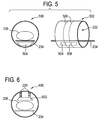
- Fig. 5 shows an end view 500 and a side view 502 of an idealized medical apparatus.
- a subject support 234 for supporting a subject 236 is visible. Beneath the subject support 234 there is a posterior coil 504 with a fixed location within the bore 222 of the medical apparatus 500, 502.
- the side view 502 shows a radiation window 506 or region where radiation enters into the bore 222.
- the area marked 508 is a region of the fixed posterior coil 504 which is exposed to radiation.
- Fig. 6 shows an end view of an idealized medical apparatus.
- the subject 236 is supported by a subject support 234.
- a subject support 234 In this case there is a fixed anterior coil 602 mounted above the subject 236 using several mounts 229.
- Fig. 7 shows an end view 700 and side view 702 of an idealized medical apparatus.
- a system transmit and/or receive coil 704 within the bore 222.
- Fig. 8 shows an end view 800 and side view 802 of an idealized medical apparatus.
- a system transmit and/or receive coil 804 in the bore 222 there is a modified posterior part 806.
- the posterior coil has been incorporated into the system and/or receive coil 804.
- the irradiation beam may pass through coils and support devices (e.g., respiratory or cardiac devices) and their cabling: These items must be positioned freely and into the vicinity of the treatment volume. This requires flexible cables.
- coils and support devices e.g., respiratory or cardiac devices
- Flexible cables may attenuate the X-ray beam in unpredictable ways. Attenuation results in uneven radiation dose to the target volume and/or may damage cables and devices themselves.
- Placing an optical shape sensing catheter inside/attaching the catheter to cabling and/or the device can be used to estimate cable and device position with good accuracy.
- the optical electronics can be located outside the beam and the positioning coordinate system fixed to ⁇ -priori known location in LINAC coordinate system.
- the position information can be fed to dose planning with known cable/device attenuation so that the beam shape and power can be adjusted to take into account the blocking items/avoid sensitive device parts.
- Another embodiment is to use the position data to avoid cabling altogether by preventing irradiation at angles where irradiation would collide with cabling or device.
- FIG. 9 shows an embodiment of a shape-sensing cable 900 according to the invention.
- This cable has a cable body 902. Within the cable body 902 there is an embedded shape-sensing fiber 904. Surrounding the shape-sensing fiber 904 there are several wires 906. This for instance could be used for a cable between a radio-frequency antenna and a transceiver. In other embodiments the exact position of the shape-sensing fiber 904 relative to the wires 906 may be different. For instance the shape-sensing fiber 904 may be applied to an outer surface of the cable 900. There also may be more or fewer wires 906 and also the wires 906 may be replaced with such things as tubes for transmitting fluids or liquids and/or fiber optic cables.
- a computer program may be stored/distributed on a suitable medium, such as an optical storage medium or a solid-state medium supplied together with or as part of other hardware, but may also be distributed in other forms, such as via the Internet or other wired or wireless telecommunication systems. Any reference signs in the claims should not be construed as limiting the scope.
Description
- The invention relates to magnetic resonance guided LINACs, in particular to the use of models to compensate for or correct for X-ray transmission through radio frequency coils.
- In standard Magnetic Resonance Imaging (MRI) systems, the posterior and anterior coils needed for signal reception from the patient, are placed around the patient and travel with the patient. This means that these coils can have a different position every time the patient is being examined. For a Magnetic Resonance (MR) imaging system combined with a LINAC (Linear Accelerator) or MR-LINAC, the radiation beams from the LINAC can potentially harm the RF coils and RF coil electronics. Coils can be designed such that they are less sensitive to radiation beams. By having too many degrees of freedom in coil placement, it can become difficult to design a coil that is insensitive for radiation in all cases.
-
WO2004/024235A1 describes a radiation therapy apparatus comprising a magnetic resonance imaging device integrated with a linear accelerator wherein a B-field compensator means is associated with the magnetic resonance imaging device which, in use, adapts the B-field produced by the magnetic resonance imaging device in the vicinity of the accelerator thereby to minimize the influence of the B-field on the particles emitted by the accelerator. -
WO2012/080948 A1 describes a radiation therapy planning and follow-up system, which includes an MR scanner with a first bore which defines an MR imaging region and a functional scanner with a second bore which defines a CT or nuclear imaging region. On the basis of MR images, CT images and PET images the radiation plan is generated or updated. - The invention provides for a medical instrument and a computer program product in the independent claims. Embodiments are given in the dependent claims.
- As will be appreciated by one skilled in the art, aspects of the present invention may be embodied as an apparatus, method or computer program product. Accordingly, aspects of the present invention may take the form of an entirely hardware embodiment, an entirely software embodiment (including firmware, resident software, microcode, etc.) or an embodiment combining software and hardware aspects that may all generally be referred to herein as a "circuit," "module" or "system." Furthermore, aspects of the present invention may take the form of a computer program product embodied in one or more computer readable medium(s) having computer executable code embodied thereon.
- Any combination of one or more computer readable medium(s) may be utilized. The computer readable medium may be a computer readable signal medium or a computer readable storage medium. A 'computer-readable storage medium' as used herein encompasses any tangible storage medium which may store instructions which are executable by a processor of a computing device. The computer-readable storage medium may be referred to as a computer-readable non-transitory storage medium. The computer-readable storage medium may also be referred to as a tangible computer readable medium. In some embodiments, a computer-readable storage medium may also be able to store data which is able to be accessed by the processor of the computing device. Examples of computer-readable storage media include, but are not limited to: a floppy disk, a magnetic hard disk drive, a solid state hard disk, flash memory, a USB thumb drive, Random Access Memory (RAM), Read Only Memory (ROM), an optical disk, a magneto-optical disk, and the register file of the processor. Examples of optical disks include Compact Disks (CD) and Digital Versatile Disks (DVD), for example CD-ROM, CD-RW, CD-R, DVD-ROM, DVD-RW, or DVD-R disks. The term computer readable-storage medium also refers to various types of recording media capable of being accessed by the computer device via a network or communication link. For example a data may be retrieved over a modem, over the internet, or over a local area network. Computer executable code embodied on a computer readable medium may be transmitted using any appropriate medium, including but not limited to wireless, wireline, optical fiber cable, RF, etc., or any suitable combination of the foregoing.
- A computer readable signal medium may include a propagated data signal with computer executable code embodied therein, for example, in baseband or as part of a carrier wave. Such a propagated signal may take any of a variety of forms, including, but not limited to, electro-magnetic, optical, or any suitable combination thereof. A computer readable signal medium may be any computer readable medium that is not a computer readable storage medium and that can communicate, propagate, or transport a program for use by or in connection with an instruction execution system, apparatus, or device.
- 'Computer memory' or 'memory' is an example of a computer-readable storage medium. Computer memory is any memory which is directly accessible to a processor. 'Computer storage' or 'storage' is a further example of a computer-readable storage medium. Computer storage is any non-volatile computer-readable storage medium. In some embodiments computer storage may also be computer memory or vice versa.
- A 'processor' as used herein encompasses an electronic component which is able to execute a program or machine executable instruction or computer executable code. References to the computing device comprising "a processor" should be interpreted as possibly containing more than one processor or processing core. The processor may for instance be a multi-core processor. A processor may also refer to a collection of processors within a single computer system or distributed amongst multiple computer systems. The term computing device should also be interpreted to possibly refer to a collection or network of computing devices each comprising a processor or processors. The computer executable code may be executed by multiple processors that may be within the same computing device or which may even be distributed across multiple computing devices.
- Computer executable code may comprise machine executable instructions or a program which causes a processor to perform an aspect of the present invention. Computer executable code for carrying out operations for aspects of the present invention may be written in any combination of one or more programming languages, including an object oriented programming language such as Java, Smalltalk, C++ or the like and conventional procedural programming languages, such as the "C" programming language or similar programming languages and compiled into machine executable instructions. In some instances the computer executable code may be in the form of a high level language or in a pre-compiled form and be used in conjunction with an interpreter which generates the machine executable instructions on the fly.
- The computer executable code may execute entirely on the user's computer, partly on the user's computer, as a stand-alone software package, partly on the user's computer and partly on a remote computer or entirely on the remote computer or server. In the latter scenario, the remote computer may be connected to the user's computer through any type of network, including a local area network (LAN) or a wide area network (WAN), or the connection may be made to an external computer (for example, through the Internet using an Internet Service Provider).
- Aspects of the present invention are described with reference to flowchart illustrations and/or block diagrams of methods, apparatus (systems) and computer program products according to embodiments of the invention. It will be understood that each block or a portion of the blocks of the flowchart, illustrations, and/or block diagrams, can be implemented by computer program instructions in form of computer executable code when applicable. It is further under stood that, when not mutually exclusive, combinations of blocks in different flowcharts, illustrations, and/or block diagrams may be combined. These computer program instructions may be provided to a processor of a general purpose computer, special purpose computer, or other programmable data processing apparatus to produce a machine, such that the instructions, which execute via the processor of the computer or other programmable data processing apparatus, create means for implementing the functions/acts specified in the flowchart and/or block diagram block or blocks.
- These computer program instructions may also be stored in a computer readable medium that can direct a computer, other programmable data processing apparatus, or other devices to function in a particular manner, such that the instructions stored in the computer readable medium produce an article of manufacture including instructions which implement the function/act specified in the flowchart and/or block diagram block or blocks.
- The computer program instructions may also be loaded onto a computer, other programmable data processing apparatus, or other devices to cause a series of operational steps to be performed on the computer, other programmable apparatus or other devices to produce a computer implemented process such that the instructions which execute on the computer or other programmable apparatus provide processes for implementing the functions/acts specified in the flowchart and/or block diagram block or blocks.
- A 'user interface' as used herein is an interface which allows a user or operator to interact with a computer or computer system. A 'user interface' may also be referred to as a 'human interface device.' A user interface may provide information or data to the operator and/or receive information or data from the operator. A user interface may enable input from an operator to be received by the computer and may provide output to the user from the computer. In other words, the user interface may allow an operator to control or manipulate a computer and the interface may allow the computer indicate the effects of the operator's control or manipulation. The display of data or information on a display or a graphical user interface is an example of providing information to an operator. The receiving of data through a keyboard, mouse, trackball, touchpad, pointing stick, graphics tablet, joystick, gamepad, webcam, headset, gear sticks, steering wheel, pedals, wired glove, dance pad, remote control, and accelerometer are all examples of user interface components which enable the receiving of information or data from an operator.
- A 'hardware interface' as used herein encompasses an interface which enables the processor of a computer system to interact with and/or control an external computing device and/or apparatus. A hardware interface may allow a processor to send control signals or instructions to an external computing device and/or apparatus. A hardware interface may also enable a processor to exchange data with an external computing device and/or apparatus. Examples of a hardware interface include, but are not limited to: a universal serial bus, IEEE 1394 port, parallel port, IEEE 1284 port, serial port, RS-232 port, IEEE-488 port, Bluetooth connection, Wireless local area network connection, TCP/IP connection, Ethernet connection, control voltage interface, MIDI interface, analog input interface, and digital input interface.
- A 'display' or 'display device' as used herein encompasses an output device or a user interface adapted for displaying images or data. A display may output visual, audio, and or tactile data. Examples of a display include, but are not limited to: a computer monitor, a television screen, a touch screen, tactile electronic display, Braille screen, Cathode ray tube (CRT), Storage tube, Bistable display, Electronic paper, Vector display, Flat panel display, Vacuum fluorescent display (VF), Light-emitting diode (LED) displays, Electroluminescent display (ELD), Plasma display panels (PDP), Liquid crystal display (LCD), Organic light-emitting diode displays (OLED), a projector, and Head-mounted display.
- Magnetic Resonance (MR) data is defined herein as being the recorded measurements of radio frequency signals emitted by atomic spins by the antenna of a Magnetic resonance apparatus during a magnetic resonance imaging scan. Magnetic resonance data is an example of medical image data. A Magnetic Resonance Imaging (MRI) image is defined herein as being the reconstructed two or three dimensional visualization of anatomic data contained within the magnetic resonance imaging data. This visualization can be performed using a computer. A portion of magnetic resonance data may also refer to a "shot." Navigator data is an example of magnetic resonance data, and is typically representative of a subject's location or state of motion.
- In one aspect the invention provides for a medical instrument comprising a LINAC or linear accelerator with an X-ray source for directing X-ray/gamma radiation at a target zone. The LINAC is adapted for rotating the X-ray source about an axis. Typically LINACs are mounted on a gantry which is able to rotate about an axis. The medical instrument further comprises a magnetic resonance imaging system for acquiring magnetic resonance data with one or a constellation of radio-frequency coils from an imaging zone. The target zone is within the imaging zone. The magnetic resonance imaging system comprises a magnet for generating a magnetic field within the imaging zone. The radio therapy source is adapted for rotating at least partially about the magnet. In some embodiments the X-ray radiation will pass through the magnet or a portion of the magnet. In other embodiments the magnet is designed such as a split magnet such that the X-ray radiation can avoid hitting the magnet.
- The medical instrument further comprises a processor for controlling the medical instrument. The medical instrument further comprises a memory for storing an X-ray transmission model of an accessory and for storing machine-executable instructions for execution by the processor. Execution of the instructions causes the processor to receive a treatment plan for eradiating the target zone. A treatment plan as used herein is data which specifies the treatment of a particular region or regions of a subject. A treatment plan may also contain anatomical landmarks which can be used to register the treatment plan to medical images such as a magnetic resonance image. Execution of the instructions further causes the processor to modify the treatment plan in accordance with the X-ray transmission model. As the X-ray source generates X-rays as it passes through the accessory there may be critical components which should not be irradiated and/or the radio-frequency coil may also attenuate the X-rays. The treatment plan can also be modified to avoid destroying sensitive portions of the radio-frequency coil and/or also to ensure that the radiation of the target zone is performed accurately. Execution of the instructions further causes the processor to acquire the magnetic resonance data using the magnetic resonance imaging system. Execution of the instructions further causes the processor to reconstruct a magnetic resonance image from the magnetic resonance data. Execution of the instructions further causes the processor to register a location of the target zone in the magnetic resonance image. That is to say the target zone is located in the magnetic resonance image. This enables the treatment plan to be registered to the coordinate system of the magnetic resonance imaging system and the LINAC. Execution of the instructions further cause the processor to generate control signals in accordance with the location of the target zone and the X-ray transmission model. Detailed control signals for controlling the operation of the LINAC have then been generated. Execution of the instructions further cause the processor to control the LINAC to irradiate the target zone using the control signals. Embodiments of the invention may be beneficial because it may avoid damaging the accessory and/or providing more accurate radiation of the target zone by accounting for attenuation of the X-rays through the accessory.
- In another embodiment the accessory is a radio-frequency coil. The radio-frequency coil is attached to the magnetic resonance imaging system with a predefined geometry. The control signals are also at least partially generated using the predefined geometry. That is to say the predefined geometry, the location of the target zone and the X-ray transmission model are used to generate the control signals. In this embodiment the radio-frequency coil is attached to the magnetic resonance imaging system such that there is a predefined geometry. In this way the X-ray transmission model has its coordinates defined relative to the coordinates of the medical instrument in a known fashion.
- In another embodiment the radio-frequency coil comprises a first coil under a subject support.
- In another embodiment the radio-frequency coil comprises a fixed posterior coil under a subject support.
- In another embodiment the radio-frequency coil comprises a second coil fixed above a subject support.
- In another embodiment the radio-frequency coil comprises an anterior coil fixed above a subject support.
- In another embodiment the second coil comprises a height adjustment mechanism for adjusting the height of the second coil relative to the subject. This embodiment may be beneficial because the second coil can be pre-positioned in the bore of the magnet. After the subject has been placed or positioned inside the magnet the second coil can then be adjusted to an optimal distance between the magnet and the subject. This maintains the effectiveness of the coil while maintaining the predefined geometry with respect to the magnet.
- In another embodiment the radio-frequency coil comprises a fixed system coil.
- In another embodiment the radio-frequency comprises a fixed system coil with an adapted posterior coil portion.
- In another embodiment the radio-frequency coil is operable for being attached to the subject.
- In another embodiment the accessory is any one of the following: a radio frequency coil, a transmit coil and/or a receive coil, a mask, a breathing tube, a sensor, a patient support, a fixation element, an electrode, and headphones.
- In another embodiment the accessory comprises magnetic resonance fiducial markers. Execution of the instructions further causes the processor to identify an accessory in the magnetic resonance image. The control signals are generated at least partially using the accessory location. This embodiment may be beneficial because if the accessory is attached to a subject the location of the accessory may not be referenced or known relative to the coordinate system of the medical instrument. However, using standard image processing techniques the location of the fiducial markets may be identified in the magnetic resonance image. This enables registering the location of the X-ray transmission model to the coordinate system of the medical instrument.
- In another embodiment the coil comprises a cable with a position measureing device. The position measuring device may for example be a potentiometer or potentiometers could be attached to structures to measure the position of the accessory. The position measuring device may also be, for the sake of example be, a shape-sensing fiber. A shape-sensing fiber as used herein is a cable which has shape-sensing technology and can track the position of a cable to a high degree of accuracy along its entire length. For instance Luna Innovations manufactures a shape-sensing cable which may be embedded in cables or attached to such things as surgical tools or other devices. The cable has an optical fiber with many fiber Bragg grating strain sensors along its length. Using an optical frequency domain reflectometry technique permits tens of thousands of sensors with the same nominal reflected wavelength to be read with a very high spatial resolution. This enables the tracking of a position of the cable.
- Execution of the instructions further causes the processor to determine a cable path using the shape-sensing fiber. The control signals are generated at least partially using the cable path. In some embodiments the location of the cable path may be used to avoid radiating the cable. In other embodiments the location of the cable path may be used to identify the location or orientation of the accessory. A shape-sensing fiber may also be used to identify the location of other components or sensors in the bore of the magnet. For instance temperature, EEG electrodes, or such things as a breathing tube may have their locations identified which enables the medical instrument to determine their location and avoid radiating them.
- In another embodiment the shape-sensing fiber comprises a tip. The tip has a predefined orientation relative to the accessory. The control signals are generated at least partially using the cable path and the predefined orientation.
- In another embodiment the control signals are operable for causing the X-ray source to avoid critical components. The critical components could be critical radio-frequency components in some embodiments. This embodiments may be advantageous because the critical components can be avoided which eliminates the possibility of them being damaged by the X-ray source.
- In another embodiment the control signals are operable for causing the X-ray source to compensate for the attenuation of the X-ray source by the accessory.
- In another embodiment the radio-frequency coil is a transmit coil and/or a receive coil.
- In another aspect the invention provides for a computer program product comprising machine-executable instructions for execution by a processor controlling a medical instrument and an X-ray transmission model of a accessory. The medical instrument comprises a LINAC with an X-ray source for directing X-ray radiation at a target zone. The LINAC is adapted for rotating the X-ray source about a rotational point. The medical instrument further comprises the magnetic resonance imaging system for acquiring magnetic resonance data with the accessory from an imaging zone. The target zone is within the imaging zone. The magnetic resonance imaging system comprises a magnet for generating a magnetic field within the imaging zone. The X-ray source is adapted for rotating at least partially about the magnet. Execution of the instructions causes the processor to receive a treatment plan for eradiating the target zone.
- Execution of the instructions further causes the processor to modify the treatment plan in accordance with the X-ray transmission model. Execution of the instructions further causes the processor to acquire the magnetic resonance data using the magnetic resonance imaging system. Execution of the instructions further causes the processor to reconstruct the magnetic resonance image from the magnetic resonance data. Execution of the instructions further causes the processor to register a location of the target zone in the magnetic resonance image. Execution of the instructions further causes the processor to generate control signals in accordance with the location of the target zone and the X-ray transmission model. Execution of the instructions further causes the processor to control the LINAC to irradiate the target zone using the control signals.
- In another aspect the invention provides for a method of operating a medical instrument. The medical instrument comprises a LINAC with an X-ray source for directing an X-ray radiation at a target source. The LINAC is adapted for rotating the X-ray source about a rotational point. The medical instrument further comprises a magnetic resonance imaging system for acquiring magnetic resonance data with the radio-frequency coil from an imaging zone. The target zone is within the imaging zone. The magnetic resonance imaging system comprises a magnet for generating a magnetic field within the imaging zone. The X-ray source is adapted for rotating at least partially about the magnetic. The method comprises the step of receiving a treatment plan for radiating the target zone.
- The method further comprises the step of modifying the treatment plan in accordance with the X-ray with an X-ray transmission model. The method further comprises acquiring the magnetic resonance data using the magnetic resonance imaging system. The method further comprises reconstructing a magnetic resonance image from the magnetic resonance data. The method further comprises registering a location of the target zone in the magnetic resonance image. The method further comprises generating control signals in accordance with the location of the target zone and the X-ray transmission model. The method further comprises controlling the LINAC to irradiate the target zone using the control signals.
- It is understood that one or more of the aforementioned embodiments of the invention may be combined as long as the combined embodiments are not mutually exclusive.
- In the following preferred embodiments of the invention will be described, by way of example only, and with reference to the drawings in which:
-
Fig. 1 shows a flow diagram which illustrates a method according to an embodiment of the invention; -
Fig. 2 illustrates a medical instrument according to an embodiment of the invention; -
Fig. 3 illustrates a medical instrument according to a further embodiment of the invention; -
Fig. 4 illustrates a medical instrument according to a further embodiment of the invention; -
Fig. 5 shows an idealized medical apparatus with a posterior coil beneath a subject support; -
Fig. 6 shows an idealized medical apparatus with a fixed anterior coil mounted above a subject support; -
Fig. 7 shows an idealized medical apparatus with a system transmit and/or receive coil within the bore of the magnet; -
Fig. 8 shows an idealized medical apparatus with a system transmit and/or receive coil with a modified posterior part in the bore of the magnet; and -
Fig. 9 shows an embodiment of a shape-sensing cable. - Like numbered elements in these figures are either equivalent elements or perform the same function. Elements which have been discussed previously will not necessarily be discussed in later figures if the function is equivalent.
-
Fig. 1 shows a flowchart which illustrates a method according to an embodiment of the invention. In block 100 a treatment plan was received which is descriptive of how to irradiate a target zone. Next instep 102 the treatment plan is modified in accordance with an X-ray transmission model of an accessory. Next instep 104 magnetic resonance data is acquired using a magnetic resonance imaging system. In step 106 a magnetic resonance image is reconstructed from the magnetic resonance data. Next in step 108 a location of the target zone is registered in the magnetic resonance image. Instep 110 control signals are generated in accordance with the location of the target zone and the X-ray transmission model for controlling a LINAC. Finally in step 112 a LINAC is controlled to irradiate the target zone using the control signals. -
Fig. 2 shows an embodiment of amedical apparatus 200 according to the invention. Themedical apparatus 200 comprises aLINAC 202 and a magneticresonance imaging system 204. The LINAC 402 comprises agantry 206 and aX-ray source 208. Thegantry 206 is for rotating theX-ray source 208 about an axis ofgantry rotation 240. Adjacent to theX-ray source 208 is anadjustable collimator 210. Theadjustable collimator 210 may for istance have adjustable plates for adjusting the beam profile of theX-ray source 208. The adjustable collimator may, for example, be a multi-leaf collimator. The magneticresonance imaging system 204 comprises amagnet 212. - It is also possible to use permanent or resistive magnets. The use of different types of magnets is also possible for instance it is also possible to use both a split cylindrical magnet and a so called open magnet. A split cylindrical magnet is similar to a standard cylindrical magnet, except that the cryostat has been split into two sections to allow access to the iso-plane of the magnet, such magnets may for instance be used in conjunction with charged particle beam therapy. An open magnet has two magnet sections, one above the other with a space in-between that is large enough to receive a subject: the arrangement of the two sections area similar to that of a Helmholtz coil. Open magnets are popular, because the subject is less confined. Inside the cryostat of the cylindrical magnet there is a collection of superconducting coils. The
magnet 212 shown in this embodiment is a standard cylindrical superconducting magnet. Themagnet 212 has acryostat 214 with superconducting coils within it 216. The magnet 412 has a bore 422. Within thebore 222 of thecylindrical magnet 212 there is an imaging zone where the magnetic field is strong and uniform enough to perform magnetic resonance imaging. - Within the
bore 222 of themagnet 212 is a magneticfield gradient coil 224 for acquisition of magnetic resonance data to spatially encode magnetic spins within an imaging zone of the magnet. The magneticfield gradient coil 224 is connected to a magnetic field gradient coil power supply 226. The magneticfield gradient coil 224 is intended to be representative, to allow radiation to pass through without being attenuated it will normally be a split-coil design. Typically magnetic field gradient coils contain three separate sets of coils for spatially encoding in three orthogonal spatial directions. The magnetic field gradient power supply 226 supplies current to the magnetic field gradient coils. The current supplied to the magnetic field coils is controlled as a function of time and may be ramped or pulsed. - There is a
radio frequency coil 228 connected to atransceiver 230. Theradio frequency coil 228 is adjacent to animaging zone 232 of themagnet 212. Theimaging zone 232 has a region of high magnetic field and homogeneity which is sufficient for performing magnetic resonance imaging. Theradio frequency coil 228 may is for manipulating the orientations of magnetic spins within the imaging zone and for receiving radio transmissions from spins also within the imaging zone. Theradio frequency coil 228 may also be referred to as an antenna or channel. Theradio frequency coil 228 may contain multiple coil elements. The radio frequency antenna may also be referred to as a channel. - The
radio frequency coil 228 andradio frequency transceiver 230 may be replaced by separate transmit and receive coils and a separate transmitter and receiver. It is understood that the radio frequency coil and the radio frequency transceiver are simply representative. The radio frequency antenna is intended to also represent a dedicated transmit antenna and a dedicated receive antenna. Likewise the transceiver may also represent a separate transmitter and receivers. - Also within the bore of the
magnet 222 is asubject support 234 for supporting a subject 236. Thesubject support 234 may be positioned by amechanical positioning system 237. Within the subject 236 there is atarget zone 238. The axis ofgantry rotation 240 is coaxial in this particular embodiment with the cylindrical axis of themagnet 212. Thesubject support 234 has been positioned such that thetarget zone 238 lies on theaxis 240 of gantry rotation. TheX-ray source 208 is shown as generating aradiation beam 242 which passes through thecollimator 210 and through thetarget zone 238. As theradiation source 208 is rotated about theaxis 240 thetarget zone 238 will always be targeted by theradiation beam 242. Theradiation beam 242 passes through thecryostat 214 of the magnet. The magneticfield gradient coil 224 has agap 243 which separate the magnetic field gradient coil into two sections. Thegap 243 reduced attenuation of theradiation beam 242 by the magneticfield gradient coil 224. In an alternative embodiment a split or open magnet design is used to reduce the attenuation of the X-ray beam by themagnet 212. - The radio-
frequency coil 228 can be seen as being attached to the inside of the bore of themagnet 222 byseveral mounts 229. In some embodiments themounts 229 may include a mechanism which allows the raising and lowering of the radio-frequency coil 228. In any case themounts 229 define the location of the radio-frequency coil 228 relative to themagnet 212. - The
transceiver 230, the magnetic field gradient coil power supply 226 and themechanical positioning system 237 are all shown as being connected to ahardware interface 246 of acomputer system 244. Thecomputer system 244 is shown as further comprising aprocessor 248 for executing machine executable instructions and for controlling the operation and function of the medical apparatus. Thehardware interface 246 enables theprocessor 248 to interact with and control themedical apparatus 200. Theprocessor 248 is shown as further being connected to auser interface 250,computer storage 252, andcomputer memory 254. - The
computer storage 252 is shown as containing atreatment plan 260. Thecomputer storage 252 is further shown as containing anX-ray transmission model 262 of the radio-frequency coil 228. TheX-ray transmission model 262 may comprise the location of sensitive components of the radio-frequency coil 228 and also the X-ray transmission properties of the radio-frequency coil 228. Thecomputer storage 252 is further shown as containing apulse sequence 264. A pulse sequence as used herein is a set of commands used to control various components of the magneticresonance imaging system 204 to acquiremagnetic resonance data 266. Thecomputer storage 252 is shown as containingmagnetic resonance data 266 that was acquired using the magneticresonance imaging system 204. - The
computer storage 252 is further shown as containing amagnetic resonance image 268 that was reconstructed from themagnetic resonance data 266. Thecomputer storage 252 is further shown as containing animage registration 270 of themagnetic resonance image 268. Theimage registration 270 registers the location of the image relative to the magneticresonance imaging system 204 and theLINAC 202. Thecomputer storage 252 is further shown as containing thelocation 272 of thetarget zone 238. This was identified in themagnetic resonance image 268. Thecomputer storage 252 is further shown as containing control signals 274. The control signals 274 are control signals which are used to control theLINAC 202 to irradiate thetarget zone 238. - The computer memory is shown as containing a
control module 280. The control module contains computer-executable code which enables theprocessor 248 to control the operation and function of themedical apparatus 200. For instance thecontrol module 280 may use thepulse sequence 264 to acquire themagnetic resonance data 266. Thecontrol module 280 may also use the control signals 274 to control theLINAC 202. Thecomputer memory 254 is further shown as containing a treatmentplan modification module 282. The treatmentplan modification module 282 modifies thetreatment plan 260 using the information contained in theX-ray transmission model 262. Thecomputer memory 254 is shown as further containing animage reconstruction module 284. Theimage reconstruction module 284 contains code which enables theprocessor 248 to reconstruct themagnetic resonance image 268 from themagnetic resonance data 266. - The
computer memory 254 is shown as further containing animage registration module 286. Theimage registration module 286 contains code which enables theprocessor 248 to generate theimage registration 270 in the location of thetarget zone 272 using themagnetic resonance image 268. Thecomputer memory 254 is shown as further containing a targetzone location module 288. The targetzone location module 288 contains code which enables theprocessor 248 to generate the location of thetarget zone 272 using theimage registration 270. Thecomputer memory 254 is further shown as containing a controlsignal generation module 290. The controlsignal generation module 290 contains code which enables theprocessor 248 to generate the control signals 274 from thetreatment plan 260 and the location of thetarget zone 272. Thetreatment plan 260 after it has been modified in accordance with the X-ray transmission module is used. -
Fig. 3 shows a medical apparatus according to a further embodiment of the invention. The embodiment shown inFig. 3 is similar to that shown inFig. 2 with the exception that the radio-frequency coil 328 in this embodiment is not mounted or fixed inside of thebore 222 of themagnet 212. Instead the radio-frequency coil 328 has severalfiducial markers 330. The radio-frequency coil 328 and at least thefiducial markers 330 are located within theimaging zone 232. In this embodiment theimage registration module 286 was used to detect the location of thefiducial markers 330 in themagnet resonance image 268 to generateaccessory locations 360, which is stored in thecomputer storage 252. In this embodiment the controlsignal generation module 290 additionally uses theaccessory location 360. - In conventional radiation therapy the radiation pattern is planned based on stationary images showing the patient anatomy including the targeted therapy region. The therapy is executed assuming that the patient anatomy corresponds to the situation during the time of the planning imaging typically taken earlier than the execution of the therapy. Often the human anatomy is not stationary, thus additional margins are added to the therapy so that the targeted region is sufficiently covered. This increases the radiation dose of the healthy tissue. One method to target the dose more accurately is to do the radiation therapy under image guidance (IMRT).
- In many cases imaging or therapy requires that there are accessories in the volume where the radiation is going through. An example of such accessory is anatomy specific receive coil used in the MR imaging. These coils are preferably located close to anatomy to be imaged / tracked to enable sufficient image quality. Location of the coil typically varies from patient to patient and from therapy to therapy. Accessories may be sensitive to radiation and/or may affect the radiation. Thus it is advantageous know the location of the radiation affecting parts to take them into account in the therapy. This invention proposes solution how to trace the location of such accessories and take them into account in the image guide radiation therapy.
- In
Fig. 3 the radio-frequency coil 228, or other accessory, has one or morefiducial markers 330. These markers are imaged and their positions are evaluated. Based on the positions of thefiducial markers 330 and the X-ray transmission model the location of the full accessory is calculated with respect to the image coordinates and therapy coordinates. The information of the accessory location is used to adjust the therapy. Such adjustments may comprise: - steering radiation beam direction and radiation source location so that the sensitive part of the accessory is not exposed to radiation;
- steering radiation dose and direction so that the effect of the defined accessory location and interference of the accessory to the radiation beam is compensated;
- instructing user to reposition accessory or patient so that the interference of the accessory with the radiation beam is reduced and therapy execution optimized;
- automatically (e.g. using motorized table positioning) repositioning accessory or patient so that the interference of the accessory with the radiation beam is reduced; and
- detection can be real-time to take into account the accessory location during the therapy and to adjust the therapy execution based on the accessory location.
- Implementations of the embodiment shown in
Fig. 3 may have one or more of the following features: - 1. Accessory or radio frequency coil has fiducial markers which are visible for the imaging system
- a. There is enough fiducial markers to define accessory position, orientation and shape with respect imaging coordinates
- i. Single point like fiducial could be enough if the orientation of the accessory is fixed with respect imaging system.
- ii. Two point like fiducials or one line like fiducial are sufficient to determine position and orientation of cylindrical symmetric accessory or accessory that has one rotation fixed.
- iii.Three point like fiducials or one fiducial with suitable 3-dimensional shape is sufficient to determine three position and three orientation coordinates of the accessory
- iv. There can be more fiducial markers to enable determining shape changes of non-rigid accessories or to make position and orientation detection more robust or to expand traceability to cover larger area (i.e. to guarantee that sufficient amount of fiducials are in the imaging system field of view).
- b. Fiducial markers can be passive, i.e., materials that are just visible for the used imaging modality.
- i. In case of MRI imaging the fiducials can be for example capsules filled with suitable MRI visible material. Detected nucleus can be 1H or another MRI sensitive nucleus.
- c. Fiducial markers can be active, i.e., such that they are visible only when activated
- i. In case of MRI imaging active marker could be marker that is surrounded by dedicated fiducial marker coil.
- a. There is enough fiducial markers to define accessory position, orientation and shape with respect imaging coordinates
- 2. Imaging device scans images which can be used to define the position of the accessory
- a. Imaging sequence can be 3-dimensional showing all fiducial markers separately
- b. Imaging sequence can be 2-dimensional with multiple slices showing all fiducials separately
- c. Imaging sequence can consist multiple 2-dimensional projections from which the location of the fiducials are identified
- d. Imaging sequence can consist of multiple 1-dimensional projections from which the fiducials are identified
- e. Imaging modality can be MRI.
- 3. Control software has a model of the accessory that includes
- a. information of the fiducial marker positions
- b. information of the geometrical shape of the accessory
- c. information of the different parts of accessory effect on the radiation (e.g. spatial attenuation)
- d. information of the radiation sensitivity of the different parts of the accessory
- 4. Control software evaluates the position of the accessory from the image information with respect to the radiation therapy beam direction, and based on the information it can
- a. switch off or reduce radiation if it goes through accessory region that is sensitive to radiation
- b. Calculates the attenuation of the accessory for the beam and
- i. Either increase the radiation to compensate the effect of attenuation
- ii.Or takes the attenuation into account when estimating the delivered radiation dose in the different parts of the anatomy
- c. Instructs user to reposition the accessory or patient so that it does not interfere with the planned radiation therapy or minimizes the interference with the therapy.
- i. Alternatively system can do repositioning automatically e.g. using motorized couch
- d. Detection can be repeated to monitor changes in the accessory location, in particular when the accessory position depends on the patient position.
- i. Repetition of the accessory tracing can be real-time in comparison to the expected motion so that the above corrections can be made "on-the-fly".
-
Fig. 4 shows a further embodiment of amedical apparatus 400 according to an embodiment of the invention. The embodiment shown inFig. 4 is similar to that shown inFigs. 2 and3 except in this embodiment the radio-frequency coil oraccessory 428 has its position determined by a mechanical or optical positioning measuring device such as a position potentiometer or a shape-sensingfiber 430. The positioning measuring device is connected to positioning measuringdevice electronics 432. For instance the shape-sensing fiber electronics 432 may contain the laser for use with the Bragg diffraction gradients within the shape-sensingfiber 430. There is a radio-frequency cable 434 between thetransceiver 230 and the radio-frequency coil 428. Thepositioning measuring device 430 can be attached to the radio-frequency cable 434. In this way the position of the radio-frequency cable 434 and hence the location and orientation of the radio-frequency coil 428 is known. Thepositioning measuring device 430 can be attached to the accessory directly 428. The shape-sensing fiber electronics 432 are shown as being connected to thehardware interface 246. Thepositioning measuring device 432 provides the computer system with acable path 460. Thecable path 460 is shown as being stored in thecomputer storage 252. In this embodiment the controlsignal generation module 290 uses thecable path 460 to define the location of theaccessory 428 relative to the magneticresonance imaging system 222 and theLINAC 202. - Embodiments of the invention may provide a way to reduce the degrees of freedom in order to facilitate coil design and coil life expectancy. They may also facilitates the attenuation calculations necessary to calibrate the system for treatment. Embodiments of the invention may solve one or more of the following problems:
- Reduced life expectancy of RF coils
- Difficult to determine the attenuation for the LINAC system caused by the RF coil. This is necessary for the (reverse) calculation of the radiation dose.
- Difficult coil design
- Difficult coil placement
- Patient space restrictions
- Embodiments of the invention may one or more of the following features related to RF coils are positioned with a fixed position with respect to the LINAC system, such that:
- a. The coil part that is exposed to radiation (radiation window) is optimized for life expectancy. This could be done e.g. by removing coil electronics sensitive to radiation as much as possible from the radiation window. The parts outside the radiation window don't have to be designed to be insensitive to radiation beams.
- b. The coil is still close to the patient for optimal receive (or transmit) behavior
- c. The coil is minimized in thickness to allow for as much space as possible in the bore
- By having a fixed position to the LINAC system, the attenuation relation to the LINAC should be known at all times. This facilitates (reverse) calculation of the right dose deposition for radiation treatment.
Figs. 5 through 8 illustrate several embodiments where the position of the radio frequency coil is fixed relative to the position of the LINAC system. -
Fig. 5 shows anend view 500 and aside view 502 of an idealized medical apparatus. Asubject support 234 for supporting a subject 236 is visible. Beneath thesubject support 234 there is aposterior coil 504 with a fixed location within thebore 222 of themedical apparatus side view 502 shows aradiation window 506 or region where radiation enters into thebore 222. The area marked 508 is a region of the fixedposterior coil 504 which is exposed to radiation. -
Fig. 6 shows an end view of an idealized medical apparatus. The subject 236 is supported by asubject support 234. In this case there is a fixedanterior coil 602 mounted above the subject 236 usingseveral mounts 229. -
Fig. 7 shows anend view 700 andside view 702 of an idealized medical apparatus. In this embodiment there is a system transmit and/or receivecoil 704 within thebore 222. -
Fig. 8 shows anend view 800 andside view 802 of an idealized medical apparatus. In this embodiment there is again a system transmit and/or receivecoil 804 in thebore 222. However, in this embodiment there is a modifiedposterior part 806. The posterior coil has been incorporated into the system and/or receivecoil 804. - In MR guided LINACs, the irradiation beam may pass through coils and support devices (e.g., respiratory or cardiac devices) and their cabling: These items must be positioned freely and into the vicinity of the treatment volume. This requires flexible cables.
- Flexible cables may attenuate the X-ray beam in unpredictable ways. Attenuation results in uneven radiation dose to the target volume and/or may damage cables and devices themselves.
- Placing an optical shape sensing catheter inside/attaching the catheter to cabling and/or the device can be used to estimate cable and device position with good accuracy. The optical electronics can be located outside the beam and the positioning coordinate system fixed to α-priori known location in LINAC coordinate system.
The position information can be fed to dose planning with known cable/device attenuation so that the beam shape and power can be adjusted to take into account the blocking items/avoid sensitive device parts. - Another embodiment is to use the position data to avoid cabling altogether by preventing irradiation at angles where irradiation would collide with cabling or device.
- A simplest case is to replace cable core with an optical sensor to localize the cable is illustrated in
Fig. 9. Fig. 9 shows an embodiment of a shape-sensing cable 900 according to the invention. This cable has acable body 902. Within thecable body 902 there is an embedded shape-sensingfiber 904. Surrounding the shape-sensingfiber 904 there areseveral wires 906. This for instance could be used for a cable between a radio-frequency antenna and a transceiver. In other embodiments the exact position of the shape-sensingfiber 904 relative to thewires 906 may be different. For instance the shape-sensingfiber 904 may be applied to an outer surface of thecable 900. There also may be more orfewer wires 906 and also thewires 906 may be replaced with such things as tubes for transmitting fluids or liquids and/or fiber optic cables. - While the invention has been illustrated and described in detail in the drawings and foregoing description, such illustration and description are to be considered illustrative or exemplary and not restrictive; the invention is not limited to the disclosed embodiments.
- Other variations to the disclosed embodiments can be understood and effected by those skilled in the art in practicing the claimed invention, from a study of the drawings, the disclosure, and the appended claims. In the claims, the word "comprising" does not exclude other elements or steps, and the indefinite article "a" or "an" does not exclude a plurality. A single processor or other unit may fulfill the functions of several items recited in the claims. The mere fact that certain measures are recited in mutually different dependent claims does not indicate that a combination of these measured cannot be used to advantage. A computer program may be stored/distributed on a suitable medium, such as an optical storage medium or a solid-state medium supplied together with or as part of other hardware, but may also be distributed in other forms, such as via the Internet or other wired or wireless telecommunication systems. Any reference signs in the claims should not be construed as limiting the scope.
-
- 200
- mecical apparatus
- 202
- LINAC
- 204
- magnetic resonance imaging system
- 206
- gantry
- 208
- X-ray source
- 210
- adjustable collimator
- 212
- magnet
- 214
- cryostat
- 216
- superconducting coil
- 222
- bore
- 224
- magnetic field gradient coil
- 226
- magnetic field gradient coil power supply
- 228
- radio frequency coil
- 229
- mount
- 230
- transciever
- 232
- imaging zone
- 234
- subject support
- 236
- subject
- 237
- mechanical positioning system
- 238
- target zone
- 240
- axis of gantry rotation
- 242
- radiation beam
- 443
- gap
- 244
- computer system
- 246
- hardware interface
- 248
- processor
- 250
- user interface
- 252
- computer storage
- 254
- computer memory
- 260
- treatment plan
- 262
- x-ray transmission model
- 264
- pulse sequence
- 266
- magnetic resonance data
- 268
- magnetic resonace image
- 270
- image registration
- 272
- location of target zone
- 274
- control signals
- 280
- control module
- 282
- treatment plan modification module
- 284
- image reconstruction module
- 286
- image registration module
- 288
- target zone location module
- 290
- contorl signal generation module
- 300
- medical apparatus
- 328
- radio frequency coil
- 330
- fudical marker
- 360
- accessory location
- 400
- medical apparatus
- 428
- radio frequency coil
- 430
- shape sensing fiber
- 432
- shape sensing fiber electronics
- 434
- radio frequency cable
- 460
- cable path
- 500
- end view of medical appartus
- 502
- side view of medical apparatus
- 504
- fixed posterior coil
- 506
- radiation window
- 508
- irridiated region
- 600
- end view of medical apparatus
- 602
- fixed anterior coil
- 700
- end view of medical appartus
- 702
- side view of medical apparatus
- 704
- system transmit and/or receive coil
- 800
- end view of medical appartus
- 802
- side view of medical apparatus
- 804
- system transmit and/or receive coil
- 806
- posterior part
- 900
- cable
- 902
- cable body
- 904
- shape sensing fiber
- 906
- wire
Claims (15)
- A medical instrument (200, 300, 400, 500, 502, 600, 700, 702, 800, 802) comprising:- a LINAC (202) with an X-ray source (208) for directing X-ray radiation (242) at a target zone (238), wherein the LINAC is adapted for rotating the X-ray source about a rotational axis (240),- a magnetic resonance imaging system (204) for acquiring magnetic resonance data (266) with a radio frequency coil (228, 328, 428, 504, 602, 704, 804) from an imaging zone (232), wherein the target zone is within the imaging zone, wherein the magnetic resonance imaging system comprises a magnet (212) for generating a magnetic field within the imaging zone, wherein the X-ray source is adapted for rotating at least partially about the magnet;- a processor (248) for controlling the medical instrument;- a memory (254) for storing an X-ray transmission model (262) of an accessory being sensitive to the X-ray radiation and/or affecting the X-ray radiation and for storing machine executable instructions (280, 282, 284, 286, 288, 290) for execution by the processor, wherein execution of the instructions causes the processor to:- receive (100) a treatment plan (260) for irradiating the target zone;- modify (102) the treatment plan in accordance with the X-ray transmission model such as to account for attenuation of the X-ray radiation through the accessory or such as to avoid damaging the accessory by the X-ray radiation;- acquire (104) the magnetic resonance data using the magnetic resonance imaging system;- reconstruct (106) a magnetic resonance image (268) from the magnetic resonance data;- locate the target zone (272) in the magnetic resonance image;- generate (110) control signals (274) in accordance with the location of the target zone and the modified X-ray transmission model; and- control (112) the LINAC to irradiate the target zone using the control signals.
- The medical instrument of claim 1, wherein the accessory is the radio frequency coil, wherein the radio frequency coil is attached to the magnetic resonance imaging system with a predefined geometry, wherein the control signals are generated using the predefined geometry.
- The medical instrument of claim 2, wherein the radio frequency coil comprises a first coil under a subject support.
- The medical instrument of claim 2 or 3, wherein the radio frequency coil comprises a second coil fixed above a subject support.
- The medical instrument of claim 4, wherein the second coil comprises a height adjustment mechanism for adjusting the height of the second coil relative to the subject.
- The medical instrument of claim 2, wherein the radio frequency coil comprises a fixed system coil.
- The medical instrument of claim 2, wherein the radio frequency coil comprises a fixed system coil with an adapted posterior coil portion.
- The medical instrument of claim 1, wherein the accessory is any one of the following: a radio frequency coil, a transmit coil and/or a receive coil, a mask, a breathing tube, a sensor, a patient support, a fixation element, an electrode, and headphones.
- The medical instrument of claim 1 or 8, wherein the accessory is operable for being attached to the subject.
- The medical instrument of claim 9, wherein the accessory comprises magnetic resonance fiducial markers, wherein execution of the instructions further causes the processor to identify a accessory location in the magnetic resonance image, wherein the control signals are generated at least partially using the accessory location.
- The medical instrument of claim 9 or 10, wherein the accessory comprises a positioning measuring device, wherein execution of the instructions further causes the processor to identify an accessory location and/or to determine a cable path using the positioning measuring device, wherein the control signals are generated at least partially using the accessory location.
- The medical instrument of claim 11, wherein the positioning measuring device is a shape sensing fiber comprising a tip, wherein the tip has a predefined orientation relative to the radio frequency coil, and wherein the control signals are generated at least partially using the cable path and the predefined orientation.
- The medical instrument on any one of the preceding claims, wherein the control signals are operable for causing the x-ray source to avoid critical components of the accessory.
- The medical instrument of any one of the preceding claims, wherein the control signals are operable for causing the x-ray source to compensate for attenuation of the accessory by steering radiation dose and radiation beam direction.
- A computer program product comprising machine executable instructions (228, 328, 428, 504, 602, 704, 804) for execution by a processor (248) for controlling a medical instrument (200, 300, 400, 500, 502, 600, 700, 702, 800, 802) and further comprising an X-ray transmission model (262) of a radio frequency coil, wherein the medical instrument comprises a LINAC (202) with an X-ray source (208) for directing X-ray radiation (242) at a target zone (238), wherein the LINAC is adapted for rotating the X-ray source about a rotational point, wherein the medical instrument further comprises a magnetic resonance imaging system (204) for acquiring magnetic resonance data with the radio frequency coil from an imaging zone (232), wherein the target zone is within the imaging zone, wherein the magnetic resonance imaging system comprises a magnet (212) for generating a magnetic field within the imaging zone, wherein the X-ray source is adapted for rotating at least partially about the magnet, wherein execution of the instructions causes the processor to:- receive (100) a treatment plan (260) for irradiating the target zone;- modify (102) the treatment plan in accordance with the X-ray transmission model such as to account for attenuation of the X-ray radiation through the radio frequency coil or such as to avoid damaging the radio frequency coil by the X-ray radiation;- acquire (104) the magnetic resonance data using the magnetic resonance imaging system;- reconstruct (106) a magnetic resonance image (268) from the magnetic resonance data;- locate the target zone (272) in the magnetic resonance image;- generate (110) control signals (274) in accordance with the location of the target zone and the modified X-ray transmission model; and- control (112) the LINAC to irradiate the target zone using the control signals.
Priority Applications (1)
| Application Number | Priority Date | Filing Date | Title |
|---|---|---|---|
| EP13765339.0A EP2872913B1 (en) | 2012-09-18 | 2013-09-16 | Magnetic resonance guided linac |
Applications Claiming Priority (4)
| Application Number | Priority Date | Filing Date | Title |
|---|---|---|---|
| US201261702284P | 2012-09-18 | 2012-09-18 | |
| EP12184801 | 2012-09-18 | ||
| EP13765339.0A EP2872913B1 (en) | 2012-09-18 | 2013-09-16 | Magnetic resonance guided linac |
| PCT/EP2013/069149 WO2014044635A1 (en) | 2012-09-18 | 2013-09-16 | Magnetic resonance guided linac |
Publications (2)
| Publication Number | Publication Date |
|---|---|
| EP2872913A1 EP2872913A1 (en) | 2015-05-20 |
| EP2872913B1 true EP2872913B1 (en) | 2016-02-24 |
Family
ID=46970024
Family Applications (1)
| Application Number | Title | Priority Date | Filing Date |
|---|---|---|---|
| EP13765339.0A Active EP2872913B1 (en) | 2012-09-18 | 2013-09-16 | Magnetic resonance guided linac |
Country Status (7)
| Country | Link |
|---|---|
| US (1) | US9662512B2 (en) |
| EP (1) | EP2872913B1 (en) |
| JP (1) | JP6001177B2 (en) |
| CN (1) | CN104641247B (en) |
| BR (1) | BR112015005602A2 (en) |
| RU (1) | RU2631910C2 (en) |
| WO (1) | WO2014044635A1 (en) |
Cited By (6)
| Publication number | Priority date | Publication date | Assignee | Title |
|---|---|---|---|---|
| US11504550B2 (en) | 2017-03-30 | 2022-11-22 | Reflexion Medical, Inc. | Radiation therapy systems and methods with tumor tracking |
| US11511133B2 (en) | 2017-08-09 | 2022-11-29 | Reflexion Medical, Inc. | Systems and methods for fault detection in emission-guided radiotherapy |
| US11627920B2 (en) | 2008-03-14 | 2023-04-18 | Reflexion Medical, Inc. | Method and apparatus for emission guided radiation therapy |
| US11675097B2 (en) | 2017-07-11 | 2023-06-13 | Reflexion Medical, Inc. | Methods for PET detector afterglow management |
| US11794036B2 (en) | 2016-11-15 | 2023-10-24 | Reflexion Medical, Inc. | Radiation therapy patient platform |
| US11878185B2 (en) | 2015-06-10 | 2024-01-23 | Reflexion Medical, Inc. | High bandwidth binary multi-leaf collimator design |
Families Citing this family (24)
| Publication number | Priority date | Publication date | Assignee | Title |
|---|---|---|---|---|
| US20140195954A1 (en) * | 2013-01-09 | 2014-07-10 | Siemens Medical Solutions Usa, Inc. | Accessories as Workflow Priors in Medical Systems |
| EP3011357B1 (en) * | 2013-06-21 | 2022-10-12 | Koninklijke Philips N.V. | Magnet assembly for combined magnetic resonance imaging and radiation therapy |
| GB201318805D0 (en) * | 2013-10-24 | 2013-12-11 | Elekta Ab | Use of Ancillary Devices/Accessories in MR Radiotherapy Systems |
| JP6498431B2 (en) * | 2014-03-07 | 2019-04-10 | キヤノンメディカルシステムズ株式会社 | Magnetic resonance imaging apparatus and RF coil |
| RU2683995C2 (en) * | 2014-05-09 | 2019-04-03 | Конинклейке Филипс Н.В. | Therapy system containing mri module and means for determining position of rf coil |
| DE102014210458B4 (en) * | 2014-06-03 | 2016-01-14 | Siemens Aktiengesellschaft | Determining a position of a target region of a patient to be irradiated in an irradiation device |
| US10718831B2 (en) | 2014-09-01 | 2020-07-21 | Koninklijke Philips N.V. | Magnetic resonance imaging receive coil with reduced radiation attenuation |
| EP3188659B1 (en) | 2014-09-03 | 2021-10-20 | Koninklijke Philips N.V. | A magnetic resonance transmit and/or receive antenna system and radiotherapy planning computer program product |
| GB2531591B (en) | 2014-10-23 | 2017-01-11 | Elekta ltd | Combined radiotherapy and MRI apparatus |
| JP6820848B2 (en) * | 2014-12-11 | 2021-01-27 | コーニンクレッカ フィリップス エヌ ヴェKoninklijke Philips N.V. | Cable loop detection mechanism for improved MRI safety |
| WO2016096038A1 (en) * | 2014-12-19 | 2016-06-23 | Brainlab Ag | Method for optimising the position of a patient's body part relative to an irradiation source |
| CN105233425A (en) * | 2015-09-10 | 2016-01-13 | 上海联影医疗科技有限公司 | Radiation therapy system guided by magnetic resonance image |
| CN108029187A (en) * | 2015-09-11 | 2018-05-11 | 三菱电机株式会社 | Electromagnetism body support frame, electromagnet device and particle-beam therapeutic apparatus |
| US10823798B2 (en) * | 2015-10-27 | 2020-11-03 | Koninklijke Philips N.V. | Virtual CT images from magnetic resonance images |
| WO2017153122A1 (en) * | 2016-03-10 | 2017-09-14 | Koninklijke Philips N.V. | Synthetic computed tomography imaging |
| JP6965261B2 (en) * | 2016-03-17 | 2021-11-10 | コーニンクレッカ フィリップス エヌ ヴェKoninklijke Philips N.V. | MR Visible Markers for MRI Devices and MR Guided Radiation Therapy Systems |
| US11298567B2 (en) | 2016-04-28 | 2022-04-12 | Koninklijke Philips N.V. | Treatment plan evaluation tool |
| GB2563677B (en) * | 2017-06-23 | 2019-10-02 | Elekta ltd | Communication apparatus for radiation therapy device |
| EP3553546A1 (en) * | 2018-04-09 | 2019-10-16 | Koninklijke Philips N.V. | Automatic positioning of antenna connectors for magnetic resonance imaging |
| EP3866919B1 (en) | 2018-11-14 | 2023-09-20 | Shanghai United Imaging Healthcare Co., Ltd. | Radiation therapy system |
| EP3721798A1 (en) * | 2019-04-11 | 2020-10-14 | Koninklijke Philips N.V. | Combined optical image generator and optical imaging system |
| CN110907912B (en) * | 2019-11-30 | 2022-09-30 | 哈尔滨工业大学 | Pole characteristic solving method in target narrow-band mode of resonance region |
| EP3971768A1 (en) * | 2020-09-22 | 2022-03-23 | Koninklijke Philips N.V. | Detection of off-label use of a magnetic resonance imaging coil |
| EP3992656A1 (en) * | 2020-10-27 | 2022-05-04 | Koninklijke Philips N.V. | Positioning of radiofrequency coils in magnetic resonance imaging devices |
Family Cites Families (17)
| Publication number | Priority date | Publication date | Assignee | Title |
|---|---|---|---|---|
| US6810108B2 (en) * | 2001-11-02 | 2004-10-26 | Siemens Medical Solutions Usa, Inc. | System and method for positioning an electronic portal imaging device |
| GB2393373A (en) * | 2002-09-13 | 2004-03-24 | Elekta Ab | MRI in guided radiotherapy and position verification |
| RU2257177C1 (en) * | 2004-06-16 | 2005-07-27 | Центральный научно-исследовательский рентгено-радиологический институт МЗ РФ /ЦНИРРИ/ | Method of stereotaxic directing of narrow photon beam to target point of brain |
| EP1874388A4 (en) * | 2005-04-13 | 2011-09-07 | Univ Maryland | Techniques for compensating movement of a treatment target in a patient |
| CA2626538C (en) * | 2005-10-17 | 2018-01-23 | Alberta Cancer Board | Integrated external beam radiotherapy and mri system |
| DE102008007245B4 (en) * | 2007-02-28 | 2010-10-14 | Siemens Aktiengesellschaft | Combined radiotherapy and magnetic resonance device |
| US20110118588A1 (en) * | 2008-03-12 | 2011-05-19 | Giora Komblau | Combination MRI and Radiotherapy Systems and Methods of Use |
| GB2460089A (en) * | 2008-05-16 | 2009-11-18 | Elekta Ab | Coincident treatment and imaging source |
| CN102132279B (en) * | 2008-08-14 | 2020-03-03 | 皇家飞利浦电子股份有限公司 | Prospective adaptive radiation therapy planning |
| US8331531B2 (en) * | 2009-03-13 | 2012-12-11 | The Board Of Trustees Of The Leland Stanford Junior University | Configurations for integrated MRI-linear accelerators |
| CN102576060B (en) * | 2009-10-06 | 2016-05-11 | 皇家飞利浦电子股份有限公司 | The review formula of dose of radiation is calculated and improved circular economy |
| ES2654789T3 (en) * | 2009-12-28 | 2018-02-15 | Profound Medical Inc | Therapeutic device |
| DE102010001743B4 (en) * | 2010-02-10 | 2012-07-12 | Siemens Aktiengesellschaft | Device with a combination of a magnetic resonance device and a radiotherapy device |
| US8710843B2 (en) * | 2010-04-27 | 2014-04-29 | University Health Network | Magnetic resonance imaging apparatus for use with radiotherapy |
| WO2012063162A1 (en) | 2010-11-09 | 2012-05-18 | Koninklijke Philips Electronics N.V. | Magnetic resonance imaging and radiotherapy apparatus with at least two-transmit-and receive channels |
| WO2012080948A1 (en) * | 2010-12-16 | 2012-06-21 | Koninklijke Philips Electronics N.V. | Radiation therapy planning and follow-up system with large bore nuclear and magnetic resonance imaging or large bore ct and magnetic resonance imaging |
| US20130218000A1 (en) * | 2012-02-17 | 2013-08-22 | Qfix Systems, Llc | MRI Coil For Imaging Of The Breast And Thoracic Area |
-
2013
- 2013-09-16 JP JP2015531589A patent/JP6001177B2/en active Active
- 2013-09-16 US US14/427,524 patent/US9662512B2/en active Active
- 2013-09-16 BR BR112015005602A patent/BR112015005602A2/en not_active Application Discontinuation
- 2013-09-16 CN CN201380048002.1A patent/CN104641247B/en active Active
- 2013-09-16 WO PCT/EP2013/069149 patent/WO2014044635A1/en active Application Filing
- 2013-09-16 EP EP13765339.0A patent/EP2872913B1/en active Active
- 2013-09-16 RU RU2015114139A patent/RU2631910C2/en not_active IP Right Cessation
Cited By (7)
| Publication number | Priority date | Publication date | Assignee | Title |
|---|---|---|---|---|
| US11627920B2 (en) | 2008-03-14 | 2023-04-18 | Reflexion Medical, Inc. | Method and apparatus for emission guided radiation therapy |
| US11878185B2 (en) | 2015-06-10 | 2024-01-23 | Reflexion Medical, Inc. | High bandwidth binary multi-leaf collimator design |
| US11794036B2 (en) | 2016-11-15 | 2023-10-24 | Reflexion Medical, Inc. | Radiation therapy patient platform |
| US11504550B2 (en) | 2017-03-30 | 2022-11-22 | Reflexion Medical, Inc. | Radiation therapy systems and methods with tumor tracking |
| US11904184B2 (en) | 2017-03-30 | 2024-02-20 | Reflexion Medical, Inc. | Radiation therapy systems and methods with tumor tracking |
| US11675097B2 (en) | 2017-07-11 | 2023-06-13 | Reflexion Medical, Inc. | Methods for PET detector afterglow management |
| US11511133B2 (en) | 2017-08-09 | 2022-11-29 | Reflexion Medical, Inc. | Systems and methods for fault detection in emission-guided radiotherapy |
Also Published As
| Publication number | Publication date |
|---|---|
| WO2014044635A1 (en) | 2014-03-27 |
| CN104641247B (en) | 2017-04-12 |
| CN104641247A (en) | 2015-05-20 |
| RU2631910C2 (en) | 2017-09-28 |
| JP6001177B2 (en) | 2016-10-05 |
| BR112015005602A2 (en) | 2017-07-04 |
| JP2015533539A (en) | 2015-11-26 |
| US20150224341A1 (en) | 2015-08-13 |
| EP2872913A1 (en) | 2015-05-20 |
| US9662512B2 (en) | 2017-05-30 |
| RU2015114139A (en) | 2016-11-10 |
Similar Documents
| Publication | Publication Date | Title |
|---|---|---|
| EP2872913B1 (en) | Magnetic resonance guided linac | |
| US10307616B2 (en) | Medical apparatus with a radiation therapy device and a radiation detection system | |
| JP6865802B2 (en) | RF coil positioning system | |
| JP6348902B2 (en) | Magnetic resonance induction therapy by interleave scanning | |
| EP3052187B1 (en) | Alignment of the coordinate systems of external beam radiotherapy and magnetic resonance imaging systems | |
| EP3055024B1 (en) | Medical instrument for external beam radiotherapy and brachytherapy | |
| CN105051562B (en) | For the Active Compensation of the field distortion component in the magnetic resonance imaging system with rack | |
| US20140084926A1 (en) | Correcting the static magnetic field of an mri radiotherapy apparatus | |
| JP2016538092A5 (en) | ||
| JP6445582B2 (en) | Magnetic resonance antenna using electronic dosimeter | |
| US20210030306A1 (en) | Automatic positioning of antenna connectors for magnetic resonance imaging | |
| EP3381362A1 (en) | Magnetic resonance image quality determination |
Legal Events
| Date | Code | Title | Description |
|---|---|---|---|
| PUAI | Public reference made under article 153(3) epc to a published international application that has entered the european phase |
Free format text: ORIGINAL CODE: 0009012 |
|
| 17P | Request for examination filed |
Effective date: 20150211 |
|
| AK | Designated contracting states |
Kind code of ref document: A1 Designated state(s): AL AT BE BG CH CY CZ DE DK EE ES FI FR GB GR HR HU IE IS IT LI LT LU LV MC MK MT NL NO PL PT RO RS SE SI SK SM TR |
|
| AX | Request for extension of the european patent |
Extension state: BA ME |
|
| GRAP | Despatch of communication of intention to grant a patent |
Free format text: ORIGINAL CODE: EPIDOSNIGR1 |
|
| DAX | Request for extension of the european patent (deleted) | ||
| INTG | Intention to grant announced |
Effective date: 20150812 |
|
| GRAS | Grant fee paid |
Free format text: ORIGINAL CODE: EPIDOSNIGR3 |
|
| GRAA | (expected) grant |
Free format text: ORIGINAL CODE: 0009210 |
|
| AK | Designated contracting states |
Kind code of ref document: B1 Designated state(s): AL AT BE BG CH CY CZ DE DK EE ES FI FR GB GR HR HU IE IS IT LI LT LU LV MC MK MT NL NO PL PT RO RS SE SI SK SM TR |
|
| REG | Reference to a national code |
Ref country code: GB Ref legal event code: FG4D |
|
| REG | Reference to a national code |
Ref country code: CH Ref legal event code: EP |
|
| REG | Reference to a national code |
Ref country code: AT Ref legal event code: REF Ref document number: 777004 Country of ref document: AT Kind code of ref document: T Effective date: 20160315 |
|
| REG | Reference to a national code |
Ref country code: IE Ref legal event code: FG4D |
|
| REG | Reference to a national code |
Ref country code: DE Ref legal event code: R096 Ref document number: 602013005189 Country of ref document: DE |
|
| REG | Reference to a national code |
Ref country code: LT Ref legal event code: MG4D |
|
| REG | Reference to a national code |
Ref country code: NL Ref legal event code: MP Effective date: 20160224 |
|
| REG | Reference to a national code |
Ref country code: AT Ref legal event code: MK05 Ref document number: 777004 Country of ref document: AT Kind code of ref document: T Effective date: 20160224 |
|
| PG25 | Lapsed in a contracting state [announced via postgrant information from national office to epo] |
Ref country code: GR Free format text: LAPSE BECAUSE OF FAILURE TO SUBMIT A TRANSLATION OF THE DESCRIPTION OR TO PAY THE FEE WITHIN THE PRESCRIBED TIME-LIMIT Effective date: 20160525 Ref country code: NO Free format text: LAPSE BECAUSE OF FAILURE TO SUBMIT A TRANSLATION OF THE DESCRIPTION OR TO PAY THE FEE WITHIN THE PRESCRIBED TIME-LIMIT Effective date: 20160524 Ref country code: IT Free format text: LAPSE BECAUSE OF FAILURE TO SUBMIT A TRANSLATION OF THE DESCRIPTION OR TO PAY THE FEE WITHIN THE PRESCRIBED TIME-LIMIT Effective date: 20160224 Ref country code: HR Free format text: LAPSE BECAUSE OF FAILURE TO SUBMIT A TRANSLATION OF THE DESCRIPTION OR TO PAY THE FEE WITHIN THE PRESCRIBED TIME-LIMIT Effective date: 20160224 Ref country code: FI Free format text: LAPSE BECAUSE OF FAILURE TO SUBMIT A TRANSLATION OF THE DESCRIPTION OR TO PAY THE FEE WITHIN THE PRESCRIBED TIME-LIMIT Effective date: 20160224 Ref country code: ES Free format text: LAPSE BECAUSE OF FAILURE TO SUBMIT A TRANSLATION OF THE DESCRIPTION OR TO PAY THE FEE WITHIN THE PRESCRIBED TIME-LIMIT Effective date: 20160224 |
|
| PG25 | Lapsed in a contracting state [announced via postgrant information from national office to epo] |
Ref country code: LT Free format text: LAPSE BECAUSE OF FAILURE TO SUBMIT A TRANSLATION OF THE DESCRIPTION OR TO PAY THE FEE WITHIN THE PRESCRIBED TIME-LIMIT Effective date: 20160224 Ref country code: PT Free format text: LAPSE BECAUSE OF FAILURE TO SUBMIT A TRANSLATION OF THE DESCRIPTION OR TO PAY THE FEE WITHIN THE PRESCRIBED TIME-LIMIT Effective date: 20160624 Ref country code: PL Free format text: LAPSE BECAUSE OF FAILURE TO SUBMIT A TRANSLATION OF THE DESCRIPTION OR TO PAY THE FEE WITHIN THE PRESCRIBED TIME-LIMIT Effective date: 20160224 Ref country code: AT Free format text: LAPSE BECAUSE OF FAILURE TO SUBMIT A TRANSLATION OF THE DESCRIPTION OR TO PAY THE FEE WITHIN THE PRESCRIBED TIME-LIMIT Effective date: 20160224 Ref country code: LV Free format text: LAPSE BECAUSE OF FAILURE TO SUBMIT A TRANSLATION OF THE DESCRIPTION OR TO PAY THE FEE WITHIN THE PRESCRIBED TIME-LIMIT Effective date: 20160224 Ref country code: RS Free format text: LAPSE BECAUSE OF FAILURE TO SUBMIT A TRANSLATION OF THE DESCRIPTION OR TO PAY THE FEE WITHIN THE PRESCRIBED TIME-LIMIT Effective date: 20160224 Ref country code: SE Free format text: LAPSE BECAUSE OF FAILURE TO SUBMIT A TRANSLATION OF THE DESCRIPTION OR TO PAY THE FEE WITHIN THE PRESCRIBED TIME-LIMIT Effective date: 20160224 Ref country code: NL Free format text: LAPSE BECAUSE OF FAILURE TO SUBMIT A TRANSLATION OF THE DESCRIPTION OR TO PAY THE FEE WITHIN THE PRESCRIBED TIME-LIMIT Effective date: 20160224 |
|
| REG | Reference to a national code |
Ref country code: FR Ref legal event code: PLFP Year of fee payment: 4 |
|
| PG25 | Lapsed in a contracting state [announced via postgrant information from national office to epo] |
Ref country code: DK Free format text: LAPSE BECAUSE OF FAILURE TO SUBMIT A TRANSLATION OF THE DESCRIPTION OR TO PAY THE FEE WITHIN THE PRESCRIBED TIME-LIMIT Effective date: 20160224 Ref country code: EE Free format text: LAPSE BECAUSE OF FAILURE TO SUBMIT A TRANSLATION OF THE DESCRIPTION OR TO PAY THE FEE WITHIN THE PRESCRIBED TIME-LIMIT Effective date: 20160224 |
|
| REG | Reference to a national code |
Ref country code: DE Ref legal event code: R097 Ref document number: 602013005189 Country of ref document: DE |
|
| PG25 | Lapsed in a contracting state [announced via postgrant information from national office to epo] |
Ref country code: RO Free format text: LAPSE BECAUSE OF FAILURE TO SUBMIT A TRANSLATION OF THE DESCRIPTION OR TO PAY THE FEE WITHIN THE PRESCRIBED TIME-LIMIT Effective date: 20160224 Ref country code: SM Free format text: LAPSE BECAUSE OF FAILURE TO SUBMIT A TRANSLATION OF THE DESCRIPTION OR TO PAY THE FEE WITHIN THE PRESCRIBED TIME-LIMIT Effective date: 20160224 Ref country code: SK Free format text: LAPSE BECAUSE OF FAILURE TO SUBMIT A TRANSLATION OF THE DESCRIPTION OR TO PAY THE FEE WITHIN THE PRESCRIBED TIME-LIMIT Effective date: 20160224 Ref country code: CZ Free format text: LAPSE BECAUSE OF FAILURE TO SUBMIT A TRANSLATION OF THE DESCRIPTION OR TO PAY THE FEE WITHIN THE PRESCRIBED TIME-LIMIT Effective date: 20160224 |
|
| PG25 | Lapsed in a contracting state [announced via postgrant information from national office to epo] |
Ref country code: BE Free format text: LAPSE BECAUSE OF FAILURE TO SUBMIT A TRANSLATION OF THE DESCRIPTION OR TO PAY THE FEE WITHIN THE PRESCRIBED TIME-LIMIT Effective date: 20160224 |
|
| PLBE | No opposition filed within time limit |
Free format text: ORIGINAL CODE: 0009261 |
|
| STAA | Information on the status of an ep patent application or granted ep patent |
Free format text: STATUS: NO OPPOSITION FILED WITHIN TIME LIMIT |
|
| 26N | No opposition filed |
Effective date: 20161125 |
|
| PG25 | Lapsed in a contracting state [announced via postgrant information from national office to epo] |
Ref country code: SI Free format text: LAPSE BECAUSE OF FAILURE TO SUBMIT A TRANSLATION OF THE DESCRIPTION OR TO PAY THE FEE WITHIN THE PRESCRIBED TIME-LIMIT Effective date: 20160224 Ref country code: BG Free format text: LAPSE BECAUSE OF FAILURE TO SUBMIT A TRANSLATION OF THE DESCRIPTION OR TO PAY THE FEE WITHIN THE PRESCRIBED TIME-LIMIT Effective date: 20160524 |
|
| PG25 | Lapsed in a contracting state [announced via postgrant information from national office to epo] |
Ref country code: MC Free format text: LAPSE BECAUSE OF FAILURE TO SUBMIT A TRANSLATION OF THE DESCRIPTION OR TO PAY THE FEE WITHIN THE PRESCRIBED TIME-LIMIT Effective date: 20160224 |
|
| REG | Reference to a national code |
Ref country code: CH Ref legal event code: PL |
|
| REG | Reference to a national code |
Ref country code: IE Ref legal event code: MM4A |
|
| PG25 | Lapsed in a contracting state [announced via postgrant information from national office to epo] |
Ref country code: LI Free format text: LAPSE BECAUSE OF NON-PAYMENT OF DUE FEES Effective date: 20160930 Ref country code: CH Free format text: LAPSE BECAUSE OF NON-PAYMENT OF DUE FEES Effective date: 20160930 Ref country code: IE Free format text: LAPSE BECAUSE OF NON-PAYMENT OF DUE FEES Effective date: 20160916 |
|
| PG25 | Lapsed in a contracting state [announced via postgrant information from national office to epo] |
Ref country code: LU Free format text: LAPSE BECAUSE OF NON-PAYMENT OF DUE FEES Effective date: 20160916 |
|
| REG | Reference to a national code |
Ref country code: FR Ref legal event code: PLFP Year of fee payment: 5 |
|
| PG25 | Lapsed in a contracting state [announced via postgrant information from national office to epo] |
Ref country code: HU Free format text: LAPSE BECAUSE OF FAILURE TO SUBMIT A TRANSLATION OF THE DESCRIPTION OR TO PAY THE FEE WITHIN THE PRESCRIBED TIME-LIMIT; INVALID AB INITIO Effective date: 20130916 |
|
| PG25 | Lapsed in a contracting state [announced via postgrant information from national office to epo] |
Ref country code: MT Free format text: LAPSE BECAUSE OF NON-PAYMENT OF DUE FEES Effective date: 20160930 Ref country code: IS Free format text: LAPSE BECAUSE OF FAILURE TO SUBMIT A TRANSLATION OF THE DESCRIPTION OR TO PAY THE FEE WITHIN THE PRESCRIBED TIME-LIMIT Effective date: 20160224 Ref country code: CY Free format text: LAPSE BECAUSE OF FAILURE TO SUBMIT A TRANSLATION OF THE DESCRIPTION OR TO PAY THE FEE WITHIN THE PRESCRIBED TIME-LIMIT Effective date: 20160224 Ref country code: MK Free format text: LAPSE BECAUSE OF FAILURE TO SUBMIT A TRANSLATION OF THE DESCRIPTION OR TO PAY THE FEE WITHIN THE PRESCRIBED TIME-LIMIT Effective date: 20160224 |
|
| REG | Reference to a national code |
Ref country code: DE Ref legal event code: R084 Ref document number: 602013005189 Country of ref document: DE |
|
| REG | Reference to a national code |
Ref country code: GB Ref legal event code: 746 Effective date: 20180904 |
|
| REG | Reference to a national code |
Ref country code: FR Ref legal event code: PLFP Year of fee payment: 6 |
|
| PG25 | Lapsed in a contracting state [announced via postgrant information from national office to epo] |
Ref country code: AL Free format text: LAPSE BECAUSE OF FAILURE TO SUBMIT A TRANSLATION OF THE DESCRIPTION OR TO PAY THE FEE WITHIN THE PRESCRIBED TIME-LIMIT Effective date: 20160224 Ref country code: TR Free format text: LAPSE BECAUSE OF FAILURE TO SUBMIT A TRANSLATION OF THE DESCRIPTION OR TO PAY THE FEE WITHIN THE PRESCRIBED TIME-LIMIT Effective date: 20160224 |
|
| PGFP | Annual fee paid to national office [announced via postgrant information from national office to epo] |
Ref country code: FR Payment date: 20190926 Year of fee payment: 7 |
|
| PG25 | Lapsed in a contracting state [announced via postgrant information from national office to epo] |
Ref country code: FR Free format text: LAPSE BECAUSE OF NON-PAYMENT OF DUE FEES Effective date: 20200930 |
|
| PGFP | Annual fee paid to national office [announced via postgrant information from national office to epo] |
Ref country code: GB Payment date: 20230926 Year of fee payment: 11 |
|
| PGFP | Annual fee paid to national office [announced via postgrant information from national office to epo] |
Ref country code: DE Payment date: 20230928 Year of fee payment: 11 |