EP3011357B1 - Magnet assembly for combined magnetic resonance imaging and radiation therapy - Google Patents
Magnet assembly for combined magnetic resonance imaging and radiation therapy Download PDFInfo
- Publication number
- EP3011357B1 EP3011357B1 EP14733714.1A EP14733714A EP3011357B1 EP 3011357 B1 EP3011357 B1 EP 3011357B1 EP 14733714 A EP14733714 A EP 14733714A EP 3011357 B1 EP3011357 B1 EP 3011357B1
- Authority
- EP
- European Patent Office
- Prior art keywords
- annular
- cryogenic fluid
- annular section
- sections
- internal width
- Prior art date
- Legal status (The legal status is an assumption and is not a legal conclusion. Google has not performed a legal analysis and makes no representation as to the accuracy of the status listed.)
- Active
Links
- 238000001959 radiotherapy Methods 0.000 title claims description 71
- 238000002595 magnetic resonance imaging Methods 0.000 title description 9
- 239000012530 fluid Substances 0.000 claims description 44
- 239000001307 helium Substances 0.000 claims description 24
- 229910052734 helium Inorganic materials 0.000 claims description 24
- SWQJXJOGLNCZEY-UHFFFAOYSA-N helium atom Chemical compound [He] SWQJXJOGLNCZEY-UHFFFAOYSA-N 0.000 claims description 24
- 230000005855 radiation Effects 0.000 claims description 21
- 239000007788 liquid Substances 0.000 claims description 19
- 238000003384 imaging method Methods 0.000 claims description 10
- 238000004891 communication Methods 0.000 claims description 4
- 230000001419 dependent effect Effects 0.000 claims 1
- 238000001816 cooling Methods 0.000 description 5
- 239000007789 gas Substances 0.000 description 4
- 238000012423 maintenance Methods 0.000 description 3
- 210000003484 anatomy Anatomy 0.000 description 2
- 230000002238 attenuated effect Effects 0.000 description 2
- 238000013461 design Methods 0.000 description 2
- 238000005516 engineering process Methods 0.000 description 2
- 230000029058 respiratory gaseous exchange Effects 0.000 description 2
- 238000007493 shaping process Methods 0.000 description 2
- 230000002159 abnormal effect Effects 0.000 description 1
- 238000010521 absorption reaction Methods 0.000 description 1
- 230000009286 beneficial effect Effects 0.000 description 1
- 238000010276 construction Methods 0.000 description 1
- 201000010099 disease Diseases 0.000 description 1
- 208000037265 diseases, disorders, signs and symptoms Diseases 0.000 description 1
- 229940079593 drug Drugs 0.000 description 1
- 239000003814 drug Substances 0.000 description 1
- 238000007689 inspection Methods 0.000 description 1
- 238000004519 manufacturing process Methods 0.000 description 1
- 229910052751 metal Inorganic materials 0.000 description 1
- 239000002184 metal Substances 0.000 description 1
- 150000002739 metals Chemical class 0.000 description 1
- 238000000034 method Methods 0.000 description 1
- 238000012986 modification Methods 0.000 description 1
- 230000004048 modification Effects 0.000 description 1
- 238000004804 winding Methods 0.000 description 1
Images


Classifications
-
- G—PHYSICS
- G01—MEASURING; TESTING
- G01R—MEASURING ELECTRIC VARIABLES; MEASURING MAGNETIC VARIABLES
- G01R33/00—Arrangements or instruments for measuring magnetic variables
- G01R33/20—Arrangements or instruments for measuring magnetic variables involving magnetic resonance
- G01R33/44—Arrangements or instruments for measuring magnetic variables involving magnetic resonance using nuclear magnetic resonance [NMR]
- G01R33/48—NMR imaging systems
- G01R33/4808—Multimodal MR, e.g. MR combined with positron emission tomography [PET], MR combined with ultrasound or MR combined with computed tomography [CT]
-
- A—HUMAN NECESSITIES
- A61—MEDICAL OR VETERINARY SCIENCE; HYGIENE
- A61N—ELECTROTHERAPY; MAGNETOTHERAPY; RADIATION THERAPY; ULTRASOUND THERAPY
- A61N5/00—Radiation therapy
- A61N5/10—X-ray therapy; Gamma-ray therapy; Particle-irradiation therapy
- A61N5/103—Treatment planning systems
- A61N5/1039—Treatment planning systems using functional images, e.g. PET or MRI
-
- A—HUMAN NECESSITIES
- A61—MEDICAL OR VETERINARY SCIENCE; HYGIENE
- A61N—ELECTROTHERAPY; MAGNETOTHERAPY; RADIATION THERAPY; ULTRASOUND THERAPY
- A61N5/00—Radiation therapy
- A61N5/10—X-ray therapy; Gamma-ray therapy; Particle-irradiation therapy
- A61N5/1042—X-ray therapy; Gamma-ray therapy; Particle-irradiation therapy with spatial modulation of the radiation beam within the treatment head
- A61N5/1045—X-ray therapy; Gamma-ray therapy; Particle-irradiation therapy with spatial modulation of the radiation beam within the treatment head using a multi-leaf collimator, e.g. for intensity modulated radiation therapy or IMRT
-
- A—HUMAN NECESSITIES
- A61—MEDICAL OR VETERINARY SCIENCE; HYGIENE
- A61N—ELECTROTHERAPY; MAGNETOTHERAPY; RADIATION THERAPY; ULTRASOUND THERAPY
- A61N5/00—Radiation therapy
- A61N5/10—X-ray therapy; Gamma-ray therapy; Particle-irradiation therapy
- A61N5/1048—Monitoring, verifying, controlling systems and methods
- A61N5/1049—Monitoring, verifying, controlling systems and methods for verifying the position of the patient with respect to the radiation beam
-
- A—HUMAN NECESSITIES
- A61—MEDICAL OR VETERINARY SCIENCE; HYGIENE
- A61N—ELECTROTHERAPY; MAGNETOTHERAPY; RADIATION THERAPY; ULTRASOUND THERAPY
- A61N5/00—Radiation therapy
- A61N5/10—X-ray therapy; Gamma-ray therapy; Particle-irradiation therapy
- A61N5/1077—Beam delivery systems
-
- F—MECHANICAL ENGINEERING; LIGHTING; HEATING; WEAPONS; BLASTING
- F17—STORING OR DISTRIBUTING GASES OR LIQUIDS
- F17C—VESSELS FOR CONTAINING OR STORING COMPRESSED, LIQUEFIED OR SOLIDIFIED GASES; FIXED-CAPACITY GAS-HOLDERS; FILLING VESSELS WITH, OR DISCHARGING FROM VESSELS, COMPRESSED, LIQUEFIED, OR SOLIDIFIED GASES
- F17C3/00—Vessels not under pressure
- F17C3/02—Vessels not under pressure with provision for thermal insulation
- F17C3/08—Vessels not under pressure with provision for thermal insulation by vacuum spaces, e.g. Dewar flask
- F17C3/085—Cryostats
-
- G—PHYSICS
- G01—MEASURING; TESTING
- G01R—MEASURING ELECTRIC VARIABLES; MEASURING MAGNETIC VARIABLES
- G01R33/00—Arrangements or instruments for measuring magnetic variables
- G01R33/20—Arrangements or instruments for measuring magnetic variables involving magnetic resonance
- G01R33/28—Details of apparatus provided for in groups G01R33/44 - G01R33/64
- G01R33/38—Systems for generation, homogenisation or stabilisation of the main or gradient magnetic field
- G01R33/381—Systems for generation, homogenisation or stabilisation of the main or gradient magnetic field using electromagnets
- G01R33/3815—Systems for generation, homogenisation or stabilisation of the main or gradient magnetic field using electromagnets with superconducting coils, e.g. power supply therefor
-
- H—ELECTRICITY
- H01—ELECTRIC ELEMENTS
- H01F—MAGNETS; INDUCTANCES; TRANSFORMERS; SELECTION OF MATERIALS FOR THEIR MAGNETIC PROPERTIES
- H01F6/00—Superconducting magnets; Superconducting coils
- H01F6/04—Cooling
-
- H—ELECTRICITY
- H01—ELECTRIC ELEMENTS
- H01F—MAGNETS; INDUCTANCES; TRANSFORMERS; SELECTION OF MATERIALS FOR THEIR MAGNETIC PROPERTIES
- H01F6/00—Superconducting magnets; Superconducting coils
- H01F6/06—Coils, e.g. winding, insulating, terminating or casing arrangements therefor
-
- A—HUMAN NECESSITIES
- A61—MEDICAL OR VETERINARY SCIENCE; HYGIENE
- A61N—ELECTROTHERAPY; MAGNETOTHERAPY; RADIATION THERAPY; ULTRASOUND THERAPY
- A61N5/00—Radiation therapy
- A61N5/10—X-ray therapy; Gamma-ray therapy; Particle-irradiation therapy
- A61N5/1048—Monitoring, verifying, controlling systems and methods
- A61N5/1049—Monitoring, verifying, controlling systems and methods for verifying the position of the patient with respect to the radiation beam
- A61N2005/1055—Monitoring, verifying, controlling systems and methods for verifying the position of the patient with respect to the radiation beam using magnetic resonance imaging [MRI]
-
- G—PHYSICS
- G01—MEASURING; TESTING
- G01R—MEASURING ELECTRIC VARIABLES; MEASURING MAGNETIC VARIABLES
- G01R33/00—Arrangements or instruments for measuring magnetic variables
- G01R33/20—Arrangements or instruments for measuring magnetic variables involving magnetic resonance
- G01R33/28—Details of apparatus provided for in groups G01R33/44 - G01R33/64
- G01R33/38—Systems for generation, homogenisation or stabilisation of the main or gradient magnetic field
- G01R33/3804—Additional hardware for cooling or heating of the magnet assembly, for housing a cooled or heated part of the magnet assembly or for temperature control of the magnet assembly
Definitions
- the present invention generally pertains to a magnet assembly for an apparatus that combines MR imaging with radiation therapy, comprising a cryostat.
- Magnetic resonance (MR) imagers or scanners have been developed that produce images for diagnosing disease and contrasting healthy tissue from abnormal tissue.
- An MR imager or scanner typically employs a superconducting magnet to generate the large magnetic fields which it requires for operation.
- a magnet is maintained in a cryogenic environment at a temperature near absolute zero.
- the magnet includes one or more electrically conductive coils which are disposed in a cryostat and through which an electrical current circulates to create the magnetic field.
- WO 2012/143173 describes a combined MRI and radiation therapy system, comprising a magnet structure and radiation therapy equipment.
- the system comprises a magnet structure and radiation therapy equipment.
- the magnet structure comprises a number of superconducting coils jointed by a support structure and extending axially either side of a central region. Furthermore, it comprises an outer vacuum chamber (OVC) enclosing the field coil structure in an evacuated volume.
- OVC outer vacuum chamber
- a cooling arrangement comprising cooling tubes is arranged in thermal contact with the superconducting coils and arranged to receive a cryogen flowing through the cooling tubes.
- radiation therapy has been developed which can focus a radiation beam (radiotherapy beam) on a target region of interest in a patient and preferentially destroy diseased tissue while avoiding healthy tissue.
- a radiation beam radiation beam
- radiotherapy beam shaping may be performed in real time, compensating for not only daily changes in anatomy but also body movements such as breathing which occur during the treatment procedure.
- a radiotherapy beam may be rotated around a patient to deposit a focused dose of radiation at the target area (i.e., diseased tissue) while sparing the healthy tissue.
- a focused dose of radiation at the target area i.e., diseased tissue
- the radiotherapy beam may reach a patient who is enclosed with an MR imager and scanner.
- the radiation beam should pass through the MR imager or scanner in a controlled and known manner so that the magnitude and location of energy delivered by the radiotherapy beam can be accurately controlled.
- the most accurate MR imagers or scanners use high magnetic fields produced by superconducting magnets which usually are composed of thick superconducting wire windings, thin metallic shells and a large cryogenic bath (e.g., liquid helium) disposed in a cryostat.
- superconducting magnets usually are composed of thick superconducting wire windings, thin metallic shells and a large cryogenic bath (e.g., liquid helium) disposed in a cryostat.
- a radiotherapy beam is attenuated when it passes through matter such as metals or even liquid helium in a cryostat of the MR imager or scanner. If the attenuation or loss is held constant over time and angular position, it is possible to compensate or adjust for the loss so as to accurately control the magnitude and location of energy delivered by the radiotherapy beam.
- cryogenic fluid e.g., liquid helium
- the amount of liquid helium varies as a function of position within the cryostat, and the amount or volume of liquid helium through which the radiotherapy beam must pass may also be a function of angular position.
- attenuation of the radiotherapy beam is also a function of angular position.
- the invention concerns a magnet assembly for an apparatus that combines MR imagng with radiation therapy as defined in Claim 1.
- the invention also concerns an apparatus that combines MR imagng with radiation therapy and that comprises a magneet assembly as defined in Claim 1.
- Various aspects of the invention are presented in the sequel of the description.
- One aspect of the present invention provides an apparatus, comprising a radiation source configured to generate a radiotherapy beam and a magnetic resonance imager, the magnetic resonance imager including a magnet assembly as defined in claim 1.
- the magnetic resonance imager includes a cryostat.
- the cryostat comprises an inner chamber.
- the inner chamber comprises: first and second annular sections separated and spaced apart from each other along a first direction, and a third annular section extending in the first direction between the first and second annular sections and connecting the first and second annular sections to each other.
- An internal width of the third annular section in a plane perpendicular to the first direction is less than an internal width of the first section and an internal width of the second annular section.
- the radiotherapy beam can be configured to pass through the third annular section of the cryostat
- the radiation source can comprise a linear accelerator.
- the radiation source can comprise a multileaf collimator.
- the apparatus can further include superconducting coils disposed in the first and second annular sections.
- the superconducting coils can include at least a pair of first superconducting coils and a pair of second superconducting coils, wherein the first superconducting coils can be disposed closer than the second superconducting coils to the third annular section, and wherein a diameter of each of the first superconducting coils can be greater than a diameter of each of the second superconducting coils.
- the radiotherapy beam can be configured to pass between the pair of first superconducting coils.
- the first and second annular sections have disposed therein corresponding first and second annular volumes of a cryogenic fluid
- the third annular section has disposed therein a third annular volume of the cryogenic fluid
- an annular depth of the third annular volume in the plane perpendicular to the first direction is less than an annular depth of the first annular volume and an annular depth of the second annular volume.
- the apparatus can include a tubular structure extending in the first direction between the first and second annular sections.
- the cryogenic fluid can comprise liquid helium.
- the cryogenic fluid can comprise gaseous helium.
- the first internal volume and the second internal volume each can be ten times the third internal volume.
- the first internal volume and the second internal volume each can be one hundred times the third internal volume.
- the internal width of the first annular section and the internal width of the second annular section each more than ten times the internal width of the third annular section.
- the internal width of the first annular section and the internal width of the second annular section each can be more than thirty times the internal width of the third annular section.
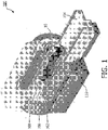
- FIG. 1 illustrates an exemplary embodiment of a magnetic resonance (MR) imager 100.
- MR imager 100 may include a magnet 102; a patient table 104 configured to hold a patient 10; gradient coils 106 configured to at least partially surround at least a portion of patient 10 for which MR imager 100 generates an image; a radio frequency coil 108 configured to apply a radio frequency signal to at least the portion of patient 10 which is being imaged, and to alter the alignment of the magnetic field; and a scanner 110 configured to detect changes in the magnetic field caused by the radio frequency signal.
- MR imager 100 may include a magnet 102; a patient table 104 configured to hold a patient 10; gradient coils 106 configured to at least partially surround at least a portion of patient 10 for which MR imager 100 generates an image; a radio frequency coil 108 configured to apply a radio frequency signal to at least the portion of patient 10 which is being imaged, and to alter the alignment of the magnetic field; and a scanner 110 configured to detect changes in the magnetic field caused by
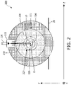
- FIG. 2 illustrates a cross-sectional view of a combined magnetic resonance (MR) imager and radiotherapy apparatus 200.
- Apparatus 200 includes a radiation source comprising a gun section 210 and a linear accelerator 212 for producing a radiotherapy beam 215.
- the radiation source may further include a multileaf collimator.
- Apparatus 200 further includes an MR imager including a cryostat 220 having a superconducting magnet (not shown) and a cryogenic fluid disposed therein for cooling the superconducting magnet.
- Cryostat 220 has an outer wall 221, an inner bore 227.
- the MR imager has an inner bore 229 inside of which is disposed patient table 104 which is configured to hold a patient 10.
- Apparatus 200 may be mounted in or on a floor 20.
- the MR imager may produce MR images of patient 10, or at least a region of interest 12 in patient 10.
- region of interest 12 may comprise diseased tissue to be treated with radiotherapy beam 215.
- radiotherapy beam 215 may be rotated around patient 10 in the Y-Z plane as denoted in FIG. 2 to provide a focused dose of radiation to region of interest 12.
- Apparatus 200 may combine the diagnostic spatial specificity of MR imaging with radiation therapy beam focus technology to provide more accurate treatment of diseased tissue while reducing damage to healthy tissue.
- beam shaping may be performed real time compensating for not only daily changes in anatomy but also body movements such as breathing, to produce a more accurate delivery of the radiotherapy beam.
- FIG. 3 conceptually illustrates one or more problems which may occur when combining a magnetic resonance (MR) imager and a radiotherapy apparatus.
- FIG. 3 illustrates a radiation source 310, generating a radiotherapy beam 315, and a cryostat 320 of the MR imager, through which radiotherapy beam 315 must pass to reach a region of interest 12, for example diseased tissue of a patient to be treated with radiotherapy beam 315.
- a radiation source 310 generating a radiotherapy beam 315
- a cryostat 320 of the MR imager through which radiotherapy beam 315 must pass to reach a region of interest 12, for example diseased tissue of a patient to be treated with radiotherapy beam 315.
- some components of the MR imager such as gradient coils, an RF coil, etc. are omitted from FIG. 3 .
- Cryostat 320 includes an inner chamber 322 which is surrounded or substantially (i.e., at least 90%) surrounded by a vacuum region 321. Disposed within inner chamber 322 are a superconducting magnet comprising superconducting coils 328 and a cryogenic fluid 323. In some embodiments, cryogenic fluid 323 may comprise liquid helium. In some embodiments, a cryogenic fluid of helium gas also may be disposed within inner chamber 322 of cryostat 320. Also disposed within inner chamber 322 are shield coils 318. In some embodiments, shield coils 318 may not be disposed within cryostat 320.
- the MR imager may produce MR images of a patient, or at least region of interest 12, in the patient.
- region of interest 12 may comprise diseased tissue to be treated with radiotherapy beam 315.
- radiation source 310 may rotate in the Y-Z plane as denoted in FIG. 3 around region of interest 12 so as to cause radiotherapy beam 315 to also be rotated around region of interest 12 to provide a focused dose of radiation to region of interest 12.
- radiotherapy beam 315 must pass through a portion of cryogenic fluid 323 to reach region of interest 12.
- Radiotherapy beam 315 is attenuated when it passes through cryogenic fluid 323 (e.g., liquid helium), and the amount of attenuation is a function of the volume or depth of cryogenic fluid 323 though which radiotherapy beam 315 passes.
- cryogenic fluid 323 e.g., liquid helium
- radiotherapy beam 315 should pass through the MR imager or scanner in a controlled and known manner so that the magnitude and location of energy delivered by radiotherapy beam 315 can be accurately controlled. Furthermore, the attenuation factor of the radiotherapy beam should be constant at various angular positions and should be kept to a minimum.
- cryogenic fluid 323 e.g., liquid helium
- the amount of cryogenic fluid 323 (e.g., liquid helium) through which radiotherapy beam 315 must pass may also be a function of angular position in the Y-Z plane, so that the attenuation of radiotherapy beam 315 is also a function of angular position in the Y-Z plane.
- some of the superconducting coils 328 are disposed in the path of radiotherapy beam 315 to reach region of interest 12. Furthermore these superconducting coils 328 cannot simply be removed without destroying the uniformity of the magnetic field which is important for generating accurate MR images.
- FIG. 4 illustrates a cross-sectional view of an embodiment of an apparatus 400 for combined magnetic resonance imaging and radiotherapy which may overcome one or more problems illustrated in FIG. 3 .
- Apparatus 400 includes a radiation source 410 and an MR imager which further includes a cryostat 420.
- a radiation source 410 and an MR imager which further includes a cryostat 420.
- cryostat 420 For simplicity of illustration, some components of the MR imager, such as gradient coils, an RF coil, etc. are omitted from FIG. 4 .
- Radiation source 410 may include a linear accelerator and a multileaf collimator which may generate a radiotherapy beam 415 as illustrated in FIG. 4 .
- Cryostat 420 includes an inner chamber 422 which is surrounded or substantially (i.e., at least 90%) surrounded by a vacuum region 421.
- Inner chamber 422 comprises a first annular section 4221 and a second annular section 4222 separated and spaced apart from each other along the X direction ("a first direction"), and a third or center annular section 4223 extending in the X direction between first and second annular sections 4221, 4222 and connecting first and second annular sections 4221, 4222 to each other.
- Inner chamber 422 is configured to hold therein a volume of a cryogenic fluid 423 when apparatus 400 is in operation.
- cryogenic fluid 423 may comprise liquid helium.
- a cryogenic fluid of helium gas also may be disposed within inner chamber 422 of cryostat 420.
- third annular section 4223 may be configured to hold therein a substantially smaller volume of cryogenic fluid 423 than each of first and second annular sections 4221, 4222 are configured to hold therein.
- first and second annular sections 4221, 4222 may hold therein a volume of cryogenic fluid 423 which is at least 100 times greater than a volume of cryogenic fluid 423 which third annular section 4223 holds therein.
- one or both of first and second annular sections 4221, 4222 may hold therein a volume of cryogenic fluid 423 which is more than 1000 times greater than a volume of cryogenic fluid 423 which third annular section 4223 holds therein.
- the average annular depth of cryogenic fluid 423 in third annular section 4223 in the Y-Z plane is substantially less than the average annular depth of cryogenic fluid 423 in one or both of first and second annular sections 4221, 4222.
- the average annular depth of cryogenic fluid 423 in third annular section 4223 may less than about 10% of the average annular depth of cryogenic fluid 423 in one or both of first and second annular sections 4221, 4222.
- the average annular depth of cryogenic fluid 423 in third annular section 4223 may about 3% of the average annular depth of cryogenic fluid 423 in one or both of first and second annular sections 4221, 4222.
- first annular section 4221 defines a first internal volume
- second annular section 4222 defines a second internal volume
- third annular section 4223 defines a third internal volume.
- first internal volume defined by first annular section 4221 and the second internal volume defined by second annular section 4222 may be at least 100 times greater than the third internal volume defined by third annular section 4223.
- first internal volume defined by first annular section 4221 and the second internal volume defined by second annular section 4222 may be at least 1000 times greater than the third internal volume defined by third annular section 4223.
- the relative sizes of the internal dimensions of inner chamber 422 in first, second and third annular sections 4221, 4222 and 4223 may be proportioned as shown, for example, in FIG. 4 .
- the internal width W3 of third annular section 4223 in the Y-Z plane perpendicular to the X direction is less than the internal width W1 of first annular section 4221 and the internal width W2 of second annular section 4222 in the Y-Z plane.
- an internal width is understood to mean a cross-sectional dimension of the interior of inner chamber 422, and thus excludes the thickness of the wall of inner chamber 422.
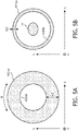
- FIG. 5A illustrates a cross-sectional view along line I-I' in FIG. 4 showing an example of a cross-section in the Y-Z plane of second annular section 4222
- FIG. 5B illustrates a cross-sectional view along line II-II' in FIG. 4 showing an example of a cross-section in the Y-Z plane of third annular section 4223 for one embodiment of apparatus 400.
- the cross-section in the Y-Z plane of first annular section 4221 may be the same as the cross-section in the Y-Z plane of second annular section 4222, and for simplicity of explanation, it will be assumed in the discussion to follow that this is the case. However, it should be understood that in general, this is not required.
- first and second annular sections 4221, 4222 are defined in part by a substantially circular outer surface 4221a and a substantially circular inner surface 4221b.
- FIGs. 4 and 5A illustrate an embodiment where inner and outer surfaces 4221a and 4221b are substantially circular, in other embodiments they may take up other shapes, for example ovular or rectangular, and they may have different shapes than each other.
- third annular section 4223 is defined in part by a substantially circular outer surface 4223a and a substantially circular inner surface 4223b.
- first and second annular sections 4221, 4222 and 4223 may take the shape of a circular ring, an ovular ring, a rectangular ring, or some other ring shape.
- FIGs. 4 and 5A-B illustrates third annular section 4223 as a single passageway connecting first and second annular sections 4221, 4222 to each other
- third annular section 4223 as a single passageway connecting first and second annular sections 4221, 4222 to each other
- other embodiments are contemplated which include multiple passageways connecting first and second annular sections 4221, 4222 to each other, so long as the level of cryogenic fluid through which radiotherapy beam 415 passes is maintained.
- inner chamber 422 of cryostat may be viewed as having a first notch of depth D1 in the outer surface thereof at center annular section 4223, and further having a second notch of depth D2 in the inner surface thereof at center annular section 4223.
- the depths D1 and D2 are equal to each other, in some embodiments the depths D1 and D2 may be different than each other. In some embodiments, the depth D1 or the depth D2 may be zero or substantially zero.
- the internal width W3 of third or central annular section 4223 may be made as thin as possible, while still providing structural integrity and allowing for thermal communication between first and second annular sections 4221, 4222 of inner chamber 422, for example by an exchange of cryogenic fluid 423 between first and second annular sections 4221, 4222 which may maintain a thermal equilibrium.
- the internal width W3 is greater than 5 mm.
- one or both of the internal width W1 of first annular section 4221 and the internal width W2 of second annular section 4222 may be more than ten times the internal width of third annular section 4223.
- the internal widths W1 and W2 may each be 500 mm, and the internal width W3 may be less than 50 mm.
- one or both of the internal width W1 of first annular section 4221 and the internal width W2 of second annular section 4222 may be more than thirty times the internal width of third annular section 4223.
- the internal widths W1 and W2 may each be about 500 mm, or approximately 500 mm, and the internal width W3 may be about 15 mm, or approximately 15 mm.
- First and second annular sections 4221, 4222 have disposed therein a plurality of superconducting coils, including first or central superconducting coil(s) 428a and second superconducting coil(s) 428b. In some embodiments, no superconducting coil(s) are disposed within third or central annular section 4223. Also disposed within first and second annular sections 4221, 4222 of inner chamber 422 are shield coils 418. In some embodiments, shield coils 418 may not be disposed within cryostat 420.
- first or central superconducting coil(s) 428a may be disposed closer than second superconducting coil(s) 428b to third annular section 4223, and the diameter of first or central superconducting coil(s) 428a may be greater than the diameter of the second superconducting coil(s) 428b which are located at opposite ends of first and second annular sections 4221, 4222. Because first or central superconducting coil(s) 428a should be outside of the path of radiotherapy beam 415, in apparatus 400 they are split farther apart in comparison to the arrangement illustrated in FIG. 3 , to permit radiotherapy beam 415 to pass therebetween.
- first or central superconducting coil(s) 428a for example with respect to second superconducting coil(s) 428b which are located at opposite ends of first and second annular sections 4221, 4222, it becomes possible to maintain a uniform magnetic field for proper MR imaging.
- tubular structure 425 extending in the X direction between first and second annular sections 4221 and 4222.
- Tubular structure 425 may pass a gas (e.g., helium gas) and/or one or more electrical wires and/or other structural components between first and second annular sections 4221 and 4222.
- gas e.g., helium gas
- tubular structure 425 may have a width or cross-section of about 5 mm.
- the MR imager may produce MR images of a patient, or at least region of interest 12, in the patient.
- region of interest 12 may comprise diseased tissue to be treated with radiotherapy beam 415.
- radiation source 410 may rotate in the Y-Z plane as denoted in FIG. 4 (the "R" direction as shown in FIG. 5A ) around region of interest 12 so as to cause radiotherapy beam 415 to also be rotated around region of interest 12 to provide a focused dose of radiation to region of interest 12.
- radiotherapy beam 415 passes through third or central annular region 4223 of inner chamber 422 of cryostat 420 to reach region of interest 12. Accordingly, radiotherapy beam 415 passes through the relatively thin volume or annular depth of cryogenic fluid 423 (e.g., liquid helium) in third or central annular region 4223, while a relatively large volume or annular depth of cryogenic fluid 423 (e.g., liquid helium) remains in the interconnected first and second annular regions 4221 and 4222 containing and cooling superconducting coils 428a, 428b.
- cryogenic fluid 423 e.g., liquid helium
- third or central annular region 4223 of inner chamber 422 has a sufficiently thin annular volume of cryogenic fluid 423 (e.g., liquid helium) in the path of radiotherapy beam 415 such that a change in the level cryogenic fluid 423 (e.g., liquid helium) does not significantly affect the dose of radiation applied to region of interest 12 of a patient 10.
- cryogenic fluid 423 e.g., liquid helium
- the relatively large volume of cryogenic fluid 423 (e.g., liquid helium) in first and second annular regions 4221 and 4222 through which radiotherapy beam 415 does not pass provides a thermal reservoir for maintenance and operation of cryostat 420.
- third or central annular region 4223 (i.e., a internal width W3 of third or central annular region 4223) is sized to allow thermal communication between first and second annular regions 4221 and 4222, allow for manufacturing tolerances, and still reduce both absorption of radiotherapy beam 415 and angular variation as radiotherapy beam 415 is rotated in the Y-Z plane. Additionally, providing a vacuum recess in vacuum region 421 from both inner wall 4221b and outer wall 4221a (i.e., depths D1 and D2 shown in FIG.
- cryostat 420 may naturally create a mechanical structure which enables first or central superconducting coils 428a to have a larger diameter/radius than superconducting coils 428b located at the opposite ends of first and second annular regions 4221 and 4222.
- first and second annular regions 4221 and 4222 of inner chamber 422 By providing thermal communication between first and second annular regions 4221 and 4222 of inner chamber 422 by means of the connected third or central annular region 4223, the design and construction of cryostat 420 may be simplified when compared, for example, to a cryostat which included two separate and thermally isolated inner chambers.
Description
- The present invention generally pertains to a magnet assembly for an apparatus that combines MR imaging with radiation therapy, comprising a cryostat.
- Magnetic resonance (MR) imagers or scanners have been developed that produce images for diagnosing disease and contrasting healthy tissue from abnormal tissue. An MR imager or scanner typically employs a superconducting magnet to generate the large magnetic fields which it requires for operation. To realize superconductivity, a magnet is maintained in a cryogenic environment at a temperature near absolute zero. Typically, the magnet includes one or more electrically conductive coils which are disposed in a cryostat and through which an electrical current circulates to create the magnetic field.
- The paper "Integrating a 1.5 T MRI scanner with a 6 MV accelerator: proof of concept", published in Physics in Medicine and Biology 54 (2009) describes a prototype MRI accelerator. The prototype is a modified 6 MV accelerator next to a modified 1.5 T MRI system. From the initial design onwards, modifications to both systems were aimed to yield simultaneous and unhampered operation of the MRI and the accelerator.
-
WO 2012/143173 describes a combined MRI and radiation therapy system, comprising a magnet structure and radiation therapy equipment. The system comprises a magnet structure and radiation therapy equipment. The magnet structure comprises a number of superconducting coils jointed by a support structure and extending axially either side of a central region. Furthermore, it comprises an outer vacuum chamber (OVC) enclosing the field coil structure in an evacuated volume. A cooling arrangement comprising cooling tubes is arranged in thermal contact with the superconducting coils and arranged to receive a cryogen flowing through the cooling tubes. - Meanwhile, radiation therapy has been developed which can focus a radiation beam (radiotherapy beam) on a target region of interest in a patient and preferentially destroy diseased tissue while avoiding healthy tissue.
- It is desired to combine the diagnostic spatial specificity of MR imaging with radiotherapy beam focus technology to provide more accurate treatment of diseased tissue while reducing the damage of healthy tissue. By combining real time imaging and radiation therapy, radiotherapy beam shaping may be performed in real time, compensating for not only daily changes in anatomy but also body movements such as breathing which occur during the treatment procedure.
- In operation, a radiotherapy beam may be rotated around a patient to deposit a focused dose of radiation at the target area (i.e., diseased tissue) while sparing the healthy tissue. Combining radiation therapy with MR imaging requires that the radiotherapy beam reach a patient who is enclosed with an MR imager and scanner. Furthermore, the radiation beam should pass through the MR imager or scanner in a controlled and known manner so that the magnitude and location of energy delivered by the radiotherapy beam can be accurately controlled.
- In general, the most accurate MR imagers or scanners use high magnetic fields produced by superconducting magnets which usually are composed of thick superconducting wire windings, thin metallic shells and a large cryogenic bath (e.g., liquid helium) disposed in a cryostat.
- A radiotherapy beam is attenuated when it passes through matter such as metals or even liquid helium in a cryostat of the MR imager or scanner. If the attenuation or loss is held constant over time and angular position, it is possible to compensate or adjust for the loss so as to accurately control the magnitude and location of energy delivered by the radiotherapy beam.
- However, during maintenance and operation of the superconducting magnet system of an MR imager or scanner, it is often the case that some amount of cryogenic fluid (e.g., liquid helium) boils off and therefore the level changes, thereby changing the attenuation of the radiotherapy beam. Furthermore, since the cryostat is typically not completely filled with liquid helium, the amount of liquid helium varies as a function of position within the cryostat, and the amount or volume of liquid helium through which the radiotherapy beam must pass may also be a function of angular position. As a result, attenuation of the radiotherapy beam is also a function of angular position. Thus it may be difficult to accurately control the amount of radiation energy delivered to a target area of interest by the radiotherapy beam to be constant, and particularly to be constant at various angular positions.
- The invention concerns a magnet assembly for an apparatus that combines MR imagng with radiation therapy as defined in Claim 1. The invention also concerns an apparatus that combines MR imagng with radiation therapy and that comprises a magneet assembly as defined in Claim 1. Various aspects of the invention are presented in the sequel of the description.
- One aspect of the present invention provides an apparatus, comprising a radiation source configured to generate a radiotherapy beam and a magnetic resonance imager, the magnetic resonance imager including a magnet assembly as defined in claim 1. The magnetic resonance imager includes a cryostat. The cryostat comprises an inner chamber.
- The inner chamber comprises:
first and second annular sections separated and spaced apart from each other along a first direction, and a third annular section extending in the first direction between the first and second annular sections and connecting the first and second annular sections to each other. An internal width of the third annular section in a plane perpendicular to the first direction is less than an internal width of the first section and an internal width of the second annular section. The radiotherapy beam can be configured to pass through the third annular section of the cryostat - In some embodiments, the radiation source can comprise a linear accelerator.
- In some embodiments, the radiation source can comprise a multileaf collimator.
- In some embodiments, the apparatus can further include superconducting coils disposed in the first and second annular sections. The superconducting coils can include at least a pair of first superconducting coils and a pair of second superconducting coils, wherein the first superconducting coils can be disposed closer than the second superconducting coils to the third annular section, and wherein a diameter of each of the first superconducting coils can be greater than a diameter of each of the second superconducting coils.
- In some embodiments, the radiotherapy beam can be configured to pass between the pair of first superconducting coils.
- According to the invention, the first and second annular sections have disposed therein corresponding first and second annular volumes of a cryogenic fluid, the third annular section has disposed therein a third annular volume of the cryogenic fluid, and an annular depth of the third annular volume in the plane perpendicular to the first direction is less than an annular depth of the first annular volume and an annular depth of the second annular volume.
- In some embodiments, the apparatus can include a tubular structure extending in the first direction between the first and second annular sections.
- In some embodiments, the cryogenic fluid can comprise liquid helium.
- In some embodiments, the cryogenic fluid can comprise gaseous helium.
- In some embodiments, the first internal volume and the second internal volume each can be ten times the third internal volume.
- In some embodiments, the first internal volume and the second internal volume each can be one hundred times the third internal volume.
- According to the invention, the internal width of the first annular section and the internal width of the second annular section each more than ten times the internal width of the third annular section.
- In some embodiments, the internal width of the first annular section and the internal width of the second annular section each can be more than thirty times the internal width of the third annular section.
- The present invention will be more readily understood from the detailed description of exemplary embodiments presented below considered in conjunction with the accompanying drawings.
-
FIG. 1 illustrates an exemplary embodiment of a magnetic resonance (MR) imager. -
FIG. 2 illustrates a cross-sectional view of a combined magnetic resonance imager and radiotherapy apparatus. -
FIG. 3 conceptually illustrates one or more problems which may occur when combining a magnetic resonance imager and a radiotherapy apparatus. -
FIG. 4 illustrates a cross-sectional view of an embodiment of an apparatus for combined magnetic resonance imaging and radiotherapy which may overcome one or more problems illustrated inFIG. 3 . -
FIGs. 5A and 5B illustrate other cross-sectional views of an embodiment of an apparatus for combined magnetic resonance imaging and radiotherapy. - The present invention will now be described more fully hereinafter with reference to the accompanying drawings, in which embodiments of the present invention are shown. The present invention may, however, be embodied in different forms and should not be construed as limited to the embodiments set forth herein. Rather, these embodiments are provided as teaching examples of the invention. Within the present disclosure and claims, when something is said to have approximately a certain value, then it means that it is within 10% of that value, and when something is said to have about a certain value, then it means that it is within 25% of that value. When something is said to be substantially greater, then it means that it is at least 10% greater, and when something is said to be substantially less, then it means that it is at least 10% less.
-
FIG. 1 illustrates an exemplary embodiment of a magnetic resonance (MR)imager 100.MR imager 100 may include amagnet 102; a patient table 104 configured to hold apatient 10; gradient coils 106 configured to at least partially surround at least a portion ofpatient 10 for whichMR imager 100 generates an image; aradio frequency coil 108 configured to apply a radio frequency signal to at least the portion ofpatient 10 which is being imaged, and to alter the alignment of the magnetic field; and ascanner 110 configured to detect changes in the magnetic field caused by the radio frequency signal. - The general operation of an MR imager is well known and therefore will not be repeated here.
-
FIG. 2 illustrates a cross-sectional view of a combined magnetic resonance (MR) imager andradiotherapy apparatus 200.Apparatus 200 includes a radiation source comprising agun section 210 and alinear accelerator 212 for producing aradiotherapy beam 215. In some embodiments, the radiation source may further include a multileaf collimator.Apparatus 200 further includes an MR imager including acryostat 220 having a superconducting magnet (not shown) and a cryogenic fluid disposed therein for cooling the superconducting magnet. For simplicity of illustration, some components of the MR imager, such as gradient coils, an RF coil, etc. are omitted fromFIG. 2 .Cryostat 220 has anouter wall 221, aninner bore 227. The MR imager has aninner bore 229 inside of which is disposed patient table 104 which is configured to hold apatient 10.Apparatus 200 may be mounted in or on afloor 20. - In operation, the MR imager may produce MR images of
patient 10, or at least a region ofinterest 12 inpatient 10. For example, region ofinterest 12 may comprise diseased tissue to be treated withradiotherapy beam 215. Meanwhile,radiotherapy beam 215 may be rotated aroundpatient 10 in the Y-Z plane as denoted inFIG. 2 to provide a focused dose of radiation to region ofinterest 12.Apparatus 200 may combine the diagnostic spatial specificity of MR imaging with radiation therapy beam focus technology to provide more accurate treatment of diseased tissue while reducing damage to healthy tissue. By combining real time imaging and radiation therapy, beam shaping may be performed real time compensating for not only daily changes in anatomy but also body movements such as breathing, to produce a more accurate delivery of the radiotherapy beam. -
FIG. 3 conceptually illustrates one or more problems which may occur when combining a magnetic resonance (MR) imager and a radiotherapy apparatus.FIG. 3 illustrates aradiation source 310, generating aradiotherapy beam 315, and acryostat 320 of the MR imager, through whichradiotherapy beam 315 must pass to reach a region ofinterest 12, for example diseased tissue of a patient to be treated withradiotherapy beam 315. For simplicity of illustration, some components of the MR imager, such as gradient coils, an RF coil, etc. are omitted fromFIG. 3 . -
Cryostat 320 includes aninner chamber 322 which is surrounded or substantially (i.e., at least 90%) surrounded by avacuum region 321. Disposed withininner chamber 322 are a superconducting magnet comprisingsuperconducting coils 328 and acryogenic fluid 323. In some embodiments,cryogenic fluid 323 may comprise liquid helium. In some embodiments, a cryogenic fluid of helium gas also may be disposed withininner chamber 322 ofcryostat 320. Also disposed withininner chamber 322 are shield coils 318. In some embodiments, shield coils 318 may not be disposed withincryostat 320. - In operation, the MR imager may produce MR images of a patient, or at least region of
interest 12, in the patient. For example, region ofinterest 12 may comprise diseased tissue to be treated withradiotherapy beam 315. Meanwhile,radiation source 310 may rotate in the Y-Z plane as denoted inFIG. 3 around region ofinterest 12 so as to causeradiotherapy beam 315 to also be rotated around region ofinterest 12 to provide a focused dose of radiation to region ofinterest 12. - As illustrated in
FIG. 3 ,radiotherapy beam 315 must pass through a portion ofcryogenic fluid 323 to reach region ofinterest 12.Radiotherapy beam 315 is attenuated when it passes through cryogenic fluid 323 (e.g., liquid helium), and the amount of attenuation is a function of the volume or depth ofcryogenic fluid 323 though whichradiotherapy beam 315 passes. - As explained above,
radiotherapy beam 315 should pass through the MR imager or scanner in a controlled and known manner so that the magnitude and location of energy delivered byradiotherapy beam 315 can be accurately controlled. Furthermore, the attenuation factor of the radiotherapy beam should be constant at various angular positions and should be kept to a minimum. - However, during maintenance and operation of the superconducting magnet system it is usual that some amount of cryogenic fluid 323 (e.g., liquid helium) boils off and therefore the volume or depth changes, thereby changing the attenuation of
radiotherapy beam 315. Furthermore, withinner chamber 322 ofcryostat 320 not being completely filled with cryogenic fluid 323 (e.g., liquid helium), the amount of cryogenic fluid 323 (e.g., liquid helium) through whichradiotherapy beam 315 must pass may also be a function of angular position in the Y-Z plane, so that the attenuation ofradiotherapy beam 315 is also a function of angular position in the Y-Z plane. Thus it may be difficult to accurately controlradiotherapy beam 315 to have a constant level, and particularly to be constant at various angular positions. - Additionally, as illustrated in
FIG. 3 , some of thesuperconducting coils 328 are disposed in the path ofradiotherapy beam 315 to reach region ofinterest 12. Furthermore thesesuperconducting coils 328 cannot simply be removed without destroying the uniformity of the magnetic field which is important for generating accurate MR images. -
FIG. 4 illustrates a cross-sectional view of an embodiment of an apparatus 400 for combined magnetic resonance imaging and radiotherapy which may overcome one or more problems illustrated inFIG. 3 . Apparatus 400 includes aradiation source 410 and an MR imager which further includes acryostat 420. For simplicity of illustration, some components of the MR imager, such as gradient coils, an RF coil, etc. are omitted fromFIG. 4 . -
Radiation source 410 may include a linear accelerator and a multileaf collimator which may generate aradiotherapy beam 415 as illustrated inFIG. 4 . -
Cryostat 420 includes aninner chamber 422 which is surrounded or substantially (i.e., at least 90%) surrounded by a vacuum region 421.Inner chamber 422 comprises a firstannular section 4221 and a secondannular section 4222 separated and spaced apart from each other along the X direction ("a first direction"), and a third or centerannular section 4223 extending in the X direction between first and secondannular sections annular sections -
Inner chamber 422 is configured to hold therein a volume of acryogenic fluid 423 when apparatus 400 is in operation. In some embodiments,cryogenic fluid 423 may comprise liquid helium. In some embodiments, a cryogenic fluid of helium gas also may be disposed withininner chamber 422 ofcryostat 420. - Beneficially, third
annular section 4223 may be configured to hold therein a substantially smaller volume ofcryogenic fluid 423 than each of first and secondannular sections annular sections cryogenic fluid 423 which is at least 100 times greater than a volume ofcryogenic fluid 423 which thirdannular section 4223 holds therein. In some embodiments, one or both of first and secondannular sections cryogenic fluid 423 which is more than 1000 times greater than a volume ofcryogenic fluid 423 which thirdannular section 4223 holds therein. - In particular, the average annular depth of
cryogenic fluid 423 in thirdannular section 4223 in the Y-Z plane (i.e., a plane perpendicular to the X direction) is substantially less than the average annular depth ofcryogenic fluid 423 in one or both of first and secondannular sections cryogenic fluid 423 in thirdannular section 4223 may less than about 10% of the average annular depth ofcryogenic fluid 423 in one or both of first and secondannular sections cryogenic fluid 423 in thirdannular section 4223 may about 3% of the average annular depth ofcryogenic fluid 423 in one or both of first and secondannular sections - Toward this end, as shown in
FIG. 4 firstannular section 4221 defines a first internal volume, secondannular section 4222 defines a second internal volume, and thirdannular section 4223 defines a third internal volume. In some embodiments, one or both of the first internal volume defined by firstannular section 4221 and the second internal volume defined by secondannular section 4222 may be at least 100 times greater than the third internal volume defined by thirdannular section 4223. In some embodiments, one or both of the first internal volume defined by firstannular section 4221 and the second internal volume defined by secondannular section 4222 may be at least 1000 times greater than the third internal volume defined by thirdannular section 4223. - To achieve this, the relative sizes of the internal dimensions of
inner chamber 422 in first, second and thirdannular sections FIG. 4 . In particular, in an embodiment as illustrated inFIG. 4 , the internal width W3 of thirdannular section 4223 in the Y-Z plane perpendicular to the X direction is less than the internal width W1 of firstannular section 4221 and the internal width W2 of secondannular section 4222 in the Y-Z plane. Here, an internal width is understood to mean a cross-sectional dimension of the interior ofinner chamber 422, and thus excludes the thickness of the wall ofinner chamber 422. -
FIG. 5A illustrates a cross-sectional view along line I-I' inFIG. 4 showing an example of a cross-section in the Y-Z plane of secondannular section 4222, andFIG. 5B illustrates a cross-sectional view along line II-II' inFIG. 4 showing an example of a cross-section in the Y-Z plane of thirdannular section 4223 for one embodiment of apparatus 400. In some embodiments, the cross-section in the Y-Z plane of firstannular section 4221 may be the same as the cross-section in the Y-Z plane of secondannular section 4222, and for simplicity of explanation, it will be assumed in the discussion to follow that this is the case. However, it should be understood that in general, this is not required. - As shown in
FIG. 4 andFIG. 5A , first and secondannular sections outer surface 4221a and a substantially circularinner surface 4221b. AlthoughFIGs. 4 and5A illustrate an embodiment where inner andouter surfaces FIG. 5B , thirdannular section 4223 is defined in part by a substantially circularouter surface 4223a and a substantially circularinner surface 4223b. AlthoughFIG. 5B illustrates an embodiment where inner andouter surfaces 4222a and 4223b are substantially circular, in other embodiments they may take up other shapes, for example ovular or rectangular, and they may have different shapes than each other. That is, first and secondannular sections - Although the embodiment of
FIGs. 4 and5A-B illustrates thirdannular section 4223 as a single passageway connecting first and secondannular sections annular sections radiotherapy beam 415 passes is maintained. - As illustrated in
FIG. 4 ,inner chamber 422 of cryostat may be viewed as having a first notch of depth D1 in the outer surface thereof at centerannular section 4223, and further having a second notch of depth D2 in the inner surface thereof at centerannular section 4223. Although as illustrated inFIGs. 4 ,5A and 5B , the depths D1 and D2 are equal to each other, in some embodiments the depths D1 and D2 may be different than each other. In some embodiments, the depth D1 or the depth D2 may be zero or substantially zero. - Beneficially, the internal width W3 of third or central
annular section 4223 may be made as thin as possible, while still providing structural integrity and allowing for thermal communication between first and secondannular sections inner chamber 422, for example by an exchange ofcryogenic fluid 423 between first and secondannular sections - In some embodiments, one or both of the internal width W1 of first
annular section 4221 and the internal width W2 of secondannular section 4222 may be more than ten times the internal width of thirdannular section 4223. For example, in some embodiments the internal widths W1 and W2 may each be 500 mm, and the internal width W3 may be less than 50 mm. - In some embodiments, one or both of the internal width W1 of first
annular section 4221 and the internal width W2 of secondannular section 4222 may be more than thirty times the internal width of thirdannular section 4223. For example, in some embodiments the internal widths W1 and W2 may each be about 500 mm, or approximately 500 mm, and the internal width W3 may be about 15 mm, or approximately 15 mm. - First and second
annular sections annular section 4223. Also disposed within first and secondannular sections inner chamber 422 are shield coils 418. In some embodiments, shield coils 418 may not be disposed withincryostat 420. - In a beneficial arrangement, as illustrated in
FIG. 4 first or central superconducting coil(s) 428a may be disposed closer than second superconducting coil(s) 428b to thirdannular section 4223, and the diameter of first or central superconducting coil(s) 428a may be greater than the diameter of the second superconducting coil(s) 428b which are located at opposite ends of first and secondannular sections radiotherapy beam 415, in apparatus 400 they are split farther apart in comparison to the arrangement illustrated inFIG. 3 , to permitradiotherapy beam 415 to pass therebetween. However, by increasing the radius/diameter of first or central superconducting coil(s) 428a, for example with respect to second superconducting coil(s) 428b which are located at opposite ends of first and secondannular sections - Also illustrated in
FIG. 4 is atubular structure 425 extending in the X direction between first and secondannular sections Tubular structure 425 may pass a gas (e.g., helium gas) and/or one or more electrical wires and/or other structural components between first and secondannular sections tubular structure 425 may have a width or cross-section of about 5 mm. - In operation, the MR imager may produce MR images of a patient, or at least region of
interest 12, in the patient. For example, region ofinterest 12 may comprise diseased tissue to be treated withradiotherapy beam 415. Meanwhile,radiation source 410 may rotate in the Y-Z plane as denoted inFIG. 4 (the "R" direction as shown inFIG. 5A ) around region ofinterest 12 so as to causeradiotherapy beam 415 to also be rotated around region ofinterest 12 to provide a focused dose of radiation to region ofinterest 12. - As illustrated in
FIG. 4 ,radiotherapy beam 415 passes through third or centralannular region 4223 ofinner chamber 422 ofcryostat 420 to reach region ofinterest 12. Accordingly,radiotherapy beam 415 passes through the relatively thin volume or annular depth of cryogenic fluid 423 (e.g., liquid helium) in third or centralannular region 4223, while a relatively large volume or annular depth of cryogenic fluid 423 (e.g., liquid helium) remains in the interconnected first and secondannular regions superconducting coils annular region 4223 ofinner chamber 422 has a sufficiently thin annular volume of cryogenic fluid 423 (e.g., liquid helium) in the path ofradiotherapy beam 415 such that a change in the level cryogenic fluid 423 (e.g., liquid helium) does not significantly affect the dose of radiation applied to region ofinterest 12 of apatient 10. Meanwhile, the relatively large volume of cryogenic fluid 423 (e.g., liquid helium) in first and secondannular regions radiotherapy beam 415 does not pass provides a thermal reservoir for maintenance and operation ofcryostat 420. Beneficially, third or central annular region 4223 (i.e., a internal width W3 of third or central annular region 4223) is sized to allow thermal communication between first and secondannular regions radiotherapy beam 415 and angular variation asradiotherapy beam 415 is rotated in the Y-Z plane. Additionally, providing a vacuum recess in vacuum region 421 from bothinner wall 4221b andouter wall 4221a (i.e., depths D1 and D2 shown inFIG. 4 ) may naturally create a mechanical structure which enables first or centralsuperconducting coils 428a to have a larger diameter/radius thansuperconducting coils 428b located at the opposite ends of first and secondannular regions annular regions inner chamber 422 by means of the connected third or centralannular region 4223, the design and construction ofcryostat 420 may be simplified when compared, for example, to a cryostat which included two separate and thermally isolated inner chambers. - While preferred embodiments are disclosed herein, many variations are possible which remain within the concept and scope of the invention. Such variations would become clear to one of ordinary skill in the art after inspection of the specification, drawings and claims herein. The present invention therefore is not to be restricted except within the scope of the appended claims.
Claims (10)
- A magnet assembly for an apparatus that combines MR imaging with radiation therapy comprising a cryostat with an innner chamber, that includes :first and second annular sections (4221, 4222) separated and spaced apart from each other along a first direction, the first and second annular sections (4221, 4222) having disposed therein corresponding first and second annular volumes of a cryogenic fluid (423), anda third annular section (4223) extending in the first direction between the first and second annular sections (4221, 4222) and connecting the first and second sections (4221, 4222) to each other allowing for thermal communication between the first and second annular sections (4221, 4222) of the inner chamber by an exchange of cryogenic fluid (423) between the first and second annular sections (4221, 4222), the third annular section (4223) having a third annular volume of the cryogenic fluid (423) disposed therein and superconducting coils for maintaining a uniform magnetic field for proper MR imaging disposed in the first and second annular sections,wherein the depth of the third annular volume of cryogenic fluid perpendicular to the first direction is less than the depth of the first annular volume of cryogenic fluid and the depth of the second annular volume of cryogenic fluid, and wherein an internal width of the first annular section (4221) in a plane perpendicular to the first direction and an internal width of the second annular section (4221) in a plane perpendicular to the first direction are each more than ten times an internal width of the third annular section (4223) in a plane perpendicular to the first direction, so that a radiotherapy beam can be configured to pass through the third annular section of the cryostat and where the internal width (W1, W2, W3) being the cross-sectional dimension of the interior of the inner chamber (422) in the respective first, second, and third annular section (4221, 4222, 4223), respectively.
- The magnet assembly of claim 1, wherein the cryogenic fluid (423) comprises liquid helium.
- The magnet assembly of claim 1, wherein the cryogenic fluid (423) comprises gaseous helium.
- The magnet assembly of claim 1, wherein the superconducting coils (428a, 428b) disposed in the first and second annular sections (4221, 4222) each include a first superconducting coil (428a) and a second superconducting coil (428b), wherein the first superconducting coil (428a) is disposed closer than the second superconducting coil (428b) to the third annular section (4223), and wherein a diameter of the first superconducting coil (428a) is greater than a diameter of the second superconducting coil (428b).
- The magnet assembly of of claim 1, wherein the internal width of the first annular section (4221) in the plane perpendicular to the first direction and the internal width of the second annular section (4222) in the plane perpendicular to the first direction are each more than thirty times the internal width of the third annular section (4223) in the plane perpendicular to the first direction.
- An apparatus that combines MR imaging with radiation therapy comprising (400), comprising:a radiation source (410) configured to generate a radiotherapy beam (415); anda magnetic resonance imager (100),wherein the magnetic resonance imager (100) includes a magnet assembly as claimed in any one of Claims 1 to 5 .
- The apparatus of claim 6, wherein the radiation source comprises a linear accelerator.
- The apparatus of claim 6, wherein the radiation source comprises a multileaf collimator.
- The apparatus of claim 6 when dependent on claim 4, wherein the radiotherapy beam (415) is configured to pass between the pair of first superconducting coils (428a).
- The apparatus of claim 6, wherein the inner chamber (422) further comprises a tubular structure (425) extending in the first direction between the first and second annular sections (4221, 4222).
Applications Claiming Priority (3)
| Application Number | Priority Date | Filing Date | Title |
|---|---|---|---|
| US201361837739P | 2013-06-21 | 2013-06-21 | |
| US201361882924P | 2013-09-26 | 2013-09-26 | |
| PCT/IB2014/061962 WO2014203105A1 (en) | 2013-06-21 | 2014-06-05 | Cryostat and system for combined magnetic resonance imaging and radiation therapy |
Publications (2)
| Publication Number | Publication Date |
|---|---|
| EP3011357A1 EP3011357A1 (en) | 2016-04-27 |
| EP3011357B1 true EP3011357B1 (en) | 2022-10-12 |
Family
ID=51022928
Family Applications (1)
| Application Number | Title | Priority Date | Filing Date |
|---|---|---|---|
| EP14733714.1A Active EP3011357B1 (en) | 2013-06-21 | 2014-06-05 | Magnet assembly for combined magnetic resonance imaging and radiation therapy |
Country Status (7)
| Country | Link |
|---|---|
| US (1) | US10729918B2 (en) |
| EP (1) | EP3011357B1 (en) |
| JP (1) | JP6475234B2 (en) |
| CN (1) | CN105393133B (en) |
| BR (1) | BR112015031515A2 (en) |
| RU (1) | RU2655686C2 (en) |
| WO (1) | WO2014203105A1 (en) |
Families Citing this family (7)
| Publication number | Priority date | Publication date | Assignee | Title |
|---|---|---|---|---|
| EP3011357B1 (en) * | 2013-06-21 | 2022-10-12 | Koninklijke Philips N.V. | Magnet assembly for combined magnetic resonance imaging and radiation therapy |
| GB2545436B (en) * | 2015-12-15 | 2018-04-11 | Siemens Healthcare Ltd | A cylindrical superconducting magnet with a shield of ferromagnetic material |
| CN109420259A (en) | 2017-08-24 | 2019-03-05 | 上海联影医疗科技有限公司 | Treatment system and the method for using treatment system |
| US11883685B2 (en) | 2017-08-24 | 2024-01-30 | Shanghai United Imaging Healthcare Co., Ltd. | Therapeutic system and method |
| CN114668987A (en) * | 2018-11-14 | 2022-06-28 | 上海联影医疗科技股份有限公司 | Radiation therapy system |
| EP4017349A4 (en) * | 2019-09-09 | 2022-09-21 | Shanghai United Imaging Healthcare Co., Ltd. | Therapeutic apparatus |
| WO2023102916A1 (en) * | 2021-12-10 | 2023-06-15 | Shanghai United Imaging Healthcare Co., Ltd. | Systems and methods for imaging and treatment |
Citations (2)
| Publication number | Priority date | Publication date | Assignee | Title |
|---|---|---|---|---|
| US5874880A (en) * | 1998-03-05 | 1999-02-23 | General Electric Company | Shielded and open superconductive magnet |
| WO2012063162A1 (en) * | 2010-11-09 | 2012-05-18 | Koninklijke Philips Electronics N.V. | Magnetic resonance imaging and radiotherapy apparatus with at least two-transmit-and receive channels |
Family Cites Families (63)
| Publication number | Priority date | Publication date | Assignee | Title |
|---|---|---|---|---|
| JPS60217608A (en) * | 1984-04-12 | 1985-10-31 | Fuji Electric Corp Res & Dev Ltd | Uniform magnetic field coil |
| US5568104A (en) * | 1995-10-23 | 1996-10-22 | General Electric Company | Open MRI superconductive magnet with cryogenic-fluid cooling |
| US5939962A (en) * | 1996-08-07 | 1999-08-17 | Mitsubishi Denki Kabushiki Kaisha | Split type magnetic field generating apparatus for MRI |
| US6591127B1 (en) * | 1999-03-15 | 2003-07-08 | General Electric Company | Integrated multi-modality imaging system and method |
| JP4179578B2 (en) | 2000-02-15 | 2008-11-12 | 株式会社日立メディコ | Open superconducting magnet and magnetic resonance imaging system using the same |
| RU2290863C2 (en) | 2004-05-14 | 2007-01-10 | ГОУ ВПО Омская Государственная Медицинская Академия | Method of inspection of condition of cryogenic cooling system of magnetic-resonance tomograph's screen |
| JP4639763B2 (en) * | 2004-11-12 | 2011-02-23 | 三菱電機株式会社 | Magnetic resonance imaging system |
| GB2427479B (en) * | 2005-06-22 | 2007-11-14 | Siemens Magnet Technology Ltd | Particle Radiation Therapy Equipment and method for performing particle radiation therapy |
| JP2007000254A (en) * | 2005-06-22 | 2007-01-11 | Mitsubishi Electric Corp | Superconduction electromagnet apparatus for mri |
| GB2427478B (en) * | 2005-06-22 | 2008-02-20 | Siemens Magnet Technology Ltd | Particle radiation therapy equipment and method for simultaneous application of magnetic resonance imaging and particle radiation |
| US8487269B2 (en) * | 2007-02-28 | 2013-07-16 | Siemens Aktiengesellschaft | Combined radiation therapy and magnetic resonance unit |
| DE102008007245B4 (en) * | 2007-02-28 | 2010-10-14 | Siemens Aktiengesellschaft | Combined radiotherapy and magnetic resonance device |
| WO2009113069A1 (en) * | 2008-03-12 | 2009-09-17 | Navotek Medical Ltd. | Combination mri and radiotherapy systems and methods of use |
| WO2011008969A1 (en) * | 2009-07-15 | 2011-01-20 | Viewray Incorporated | Method and apparatus for shielding a linear accelerator and a magnetic resonance imaging device from each other |
| JP5706901B2 (en) * | 2009-10-06 | 2015-04-22 | コーニンクレッカ フィリップス エヌ ヴェ | Retrospective calculation of radiation dose and improved treatment planning |
| US8378682B2 (en) * | 2009-11-17 | 2013-02-19 | Muralidhara Subbarao | Field image tomography for magnetic resonance imaging |
| DE102010001743B4 (en) * | 2010-02-10 | 2012-07-12 | Siemens Aktiengesellschaft | Device with a combination of a magnetic resonance device and a radiotherapy device |
| DE102010001746B4 (en) * | 2010-02-10 | 2012-03-22 | Siemens Aktiengesellschaft | Device with a combination of a magnetic resonance device and a radiotherapy device |
| WO2011106524A1 (en) * | 2010-02-24 | 2011-09-01 | Viewray Incorporated | Split magnetic resonance imaging system |
| EP2400314A1 (en) | 2010-06-14 | 2011-12-28 | Agilent Technologies U.K. Limited | Superconducting magnet arrangement and method of mounting thereof |
| CN103096975B (en) * | 2010-09-09 | 2016-10-26 | 皇家飞利浦电子股份有限公司 | For measuring the radiacmeter of the radiation dose to experimenter, therapeutic equipment and computer system during nuclear magnetic resonance |
| GB2484529B (en) * | 2010-10-15 | 2012-09-19 | Siemens Ag | Beam deflection arrangement within a combined radiation therapy and magnetic resonance unit |
| CN103200992A (en) * | 2010-11-09 | 2013-07-10 | 皇家飞利浦电子股份有限公司 | Magnetic resonance imaging system and radiotherapy apparatus with an adjustable axis of rotation |
| US9608395B2 (en) * | 2010-12-08 | 2017-03-28 | Koninklijke Philips N.V. | Slip ring assembly |
| BR112013014571A2 (en) * | 2010-12-13 | 2017-06-06 | Koninl Philips Electronics Nv | therapeutic equipment, radiotherapy equipment, computer program product and method for the control of therapeutic equipment |
| GB2490325B (en) * | 2011-04-21 | 2013-04-10 | Siemens Plc | Combined MRI and radiation therapy equipment |
| EP2715387B1 (en) * | 2011-05-31 | 2020-10-21 | Koninklijke Philips N.V. | Correcting the static magnetic field of an mri radiotherapy apparatus |
| CN103620437B (en) * | 2011-06-27 | 2017-10-27 | 皇家飞利浦有限公司 | Use the bone MRI of the fatty separating treatment of ultrashort echo time pulse train and water with FID and many gradient echo acquisitions |
| WO2013014260A1 (en) * | 2011-07-28 | 2013-01-31 | Deutsches Krebsforschungszentrum | Therapeutic device for treating a predefined body part of a patient with rays |
| US8981779B2 (en) * | 2011-12-13 | 2015-03-17 | Viewray Incorporated | Active resistive shimming fro MRI devices |
| EP2664359A1 (en) * | 2012-05-14 | 2013-11-20 | Koninklijke Philips N.V. | Magnetic resonance guided therapy with interleaved scanning |
| WO2013190413A1 (en) * | 2012-06-20 | 2013-12-27 | Koninklijke Philips N.V. | Graphical user interface for medical instruments |
| BR112015005602A2 (en) * | 2012-09-18 | 2017-07-04 | Koninklijke Philips Nv | medical instrument and computer program product |
| GB2507792B (en) * | 2012-11-12 | 2015-07-01 | Siemens Plc | Combined MRI and radiation therapy system |
| CN104884967B (en) * | 2012-12-17 | 2018-05-22 | 皇家飞利浦有限公司 | Low-loss persistent current switch with heat transfer unit (HTU) |
| WO2014121991A1 (en) * | 2013-02-06 | 2014-08-14 | Koninklijke Philips N.V. | Active compensation for field distorting components in a magnetic resonance imaging system with a gantry |
| US9404983B2 (en) * | 2013-03-12 | 2016-08-02 | Viewray, Incorporated | Radio frequency transmit coil for magnetic resonance imaging system |
| US9675271B2 (en) * | 2013-03-13 | 2017-06-13 | Viewray Technologies, Inc. | Systems and methods for radiotherapy with magnetic resonance imaging |
| CN105190343B (en) * | 2013-03-14 | 2019-03-01 | 皇家飞利浦有限公司 | The electrical lead of gas flow reduction for superconducting magnet system |
| EP2986340B1 (en) * | 2013-04-18 | 2016-11-23 | Koninklijke Philips N.V. | Radiation therapy system with real-time magnetic resonance monitoring |
| EP3011357B1 (en) * | 2013-06-21 | 2022-10-12 | Koninklijke Philips N.V. | Magnet assembly for combined magnetic resonance imaging and radiation therapy |
| CN105453197B (en) * | 2013-07-26 | 2018-06-08 | 皇家飞利浦有限公司 | For the method and apparatus of the cooling circuit in response to magnetic field control superconducting magnet system |
| CN105611967B (en) * | 2013-09-30 | 2019-05-14 | 皇家飞利浦有限公司 | External beam radiation therapy is aligned with the coordinate system of magnetic resonance imaging system |
| JP6113919B2 (en) * | 2013-10-17 | 2017-04-12 | コーニンクレッカ フィリップス エヌ ヴェKoninklijke Philips N.V. | Medical device with radiation therapy device and radiation detection system |
| CN105745555B (en) * | 2013-11-08 | 2019-03-08 | 皇家飞利浦有限公司 | Medical apparatus for radiation therapy and Ultrasonic Heating |
| CN105745553B (en) * | 2013-11-13 | 2019-11-05 | 皇家飞利浦有限公司 | The superconducting magnet system of system and the method for cooling superconducting magnets system are effectively crossed over including calorifics |
| JP6445582B2 (en) * | 2014-03-13 | 2018-12-26 | コーニンクレッカ フィリップス エヌ ヴェKoninklijke Philips N.V. | Magnetic resonance antenna using electronic dosimeter |
| RU2683995C2 (en) * | 2014-05-09 | 2019-04-03 | Конинклейке Филипс Н.В. | Therapy system containing mri module and means for determining position of rf coil |
| WO2015177667A2 (en) * | 2014-05-21 | 2015-11-26 | Koninklijke Philips N.V. | Superconducting coil support device and method and apparatus including superconducting coil support device |
| US9943703B2 (en) * | 2014-07-28 | 2018-04-17 | The University Of Maryland, Baltimore | System and method for irradiation therapy using voxel based functional measurements of organs at risk |
| US10256021B2 (en) * | 2014-09-09 | 2019-04-09 | Koninklijke Philips N.V. | Superconducting magnet with cryogenic thermal buffer |
| GB2531591B (en) * | 2014-10-23 | 2017-01-11 | Elekta ltd | Combined radiotherapy and MRI apparatus |
| US10413253B2 (en) * | 2014-11-21 | 2019-09-17 | Samsung Electronics Co., Ltd. | Method and apparatus for processing medical image |
| US11045108B2 (en) * | 2014-11-26 | 2021-06-29 | Viewray Technologies, Inc. | Magnetic resonance imaging receive coil assembly |
| CN107110927B (en) * | 2014-12-12 | 2020-03-03 | 皇家飞利浦有限公司 | System and method for maintaining vacuum in superconducting magnet system in quench condition |
| WO2016166071A1 (en) * | 2015-04-14 | 2016-10-20 | Koninklijke Philips N.V. | Radiotherapy planning with improved accuracy |
| DE102015213730B4 (en) * | 2015-07-21 | 2017-03-23 | Siemens Healthcare Gmbh | Quality control of treatment planning by comparing first and second MR-based dose distributions in the planning volume |
| US10252083B2 (en) * | 2015-09-23 | 2019-04-09 | Varian Medical Systems Inc. | Systems, methods, and devices for high-energy irradiation |
| DE102016200433A1 (en) * | 2016-01-15 | 2017-07-20 | Siemens Healthcare Gmbh | Method for planning an irradiation of a patient |
| EP3430416A1 (en) * | 2016-03-17 | 2019-01-23 | Koninklijke Philips N.V. | Mr-visible marker for an mri apparatus and an mr guided radiation therapy system |
| US20170368373A1 (en) * | 2016-06-22 | 2017-12-28 | Velayudhan Sahadevan | Device and Methods for Broadbeam and Microbeam Chemo-Radiosurgery Combined with Its Tumor Exosome Apheresis |
| WO2018093933A1 (en) * | 2016-11-15 | 2018-05-24 | Reflexion Medical, Inc. | System for emission-guided high-energy photon delivery |
| JP7286272B2 (en) | 2018-06-21 | 2023-06-05 | キヤノン株式会社 | Information processing device, information processing method and program |
-
2014
- 2014-06-05 EP EP14733714.1A patent/EP3011357B1/en active Active
- 2014-06-05 RU RU2016101579A patent/RU2655686C2/en active
- 2014-06-05 US US14/898,769 patent/US10729918B2/en active Active
- 2014-06-05 BR BR112015031515A patent/BR112015031515A2/en not_active Application Discontinuation
- 2014-06-05 JP JP2016520771A patent/JP6475234B2/en active Active
- 2014-06-05 CN CN201480034823.4A patent/CN105393133B/en active Active
- 2014-06-05 WO PCT/IB2014/061962 patent/WO2014203105A1/en active Application Filing
Patent Citations (2)
| Publication number | Priority date | Publication date | Assignee | Title |
|---|---|---|---|---|
| US5874880A (en) * | 1998-03-05 | 1999-02-23 | General Electric Company | Shielded and open superconductive magnet |
| WO2012063162A1 (en) * | 2010-11-09 | 2012-05-18 | Koninklijke Philips Electronics N.V. | Magnetic resonance imaging and radiotherapy apparatus with at least two-transmit-and receive channels |
Also Published As
| Publication number | Publication date |
|---|---|
| CN105393133A (en) | 2016-03-09 |
| RU2016101579A (en) | 2017-07-24 |
| WO2014203105A1 (en) | 2014-12-24 |
| JP2016526411A (en) | 2016-09-05 |
| RU2655686C2 (en) | 2018-05-29 |
| EP3011357A1 (en) | 2016-04-27 |
| JP6475234B2 (en) | 2019-02-27 |
| US10729918B2 (en) | 2020-08-04 |
| CN105393133B (en) | 2019-06-04 |
| BR112015031515A2 (en) | 2017-07-25 |
| US20160136456A1 (en) | 2016-05-19 |
Similar Documents
| Publication | Publication Date | Title |
|---|---|---|
| EP3011357B1 (en) | Magnet assembly for combined magnetic resonance imaging and radiation therapy | |
| KR101423607B1 (en) | Combined mri and radiation therapy equipment | |
| US7960710B2 (en) | Particle radiation therapy equipment | |
| JP5732065B2 (en) | Self-shielding gradient coil | |
| CN102145206B (en) | There is the equipment of the combination of magnetic resonance device and radiation treatment device | |
| CN102472830B (en) | For making linear accelerator and MR imaging apparatus method and apparatus shielded from one another | |
| US5396207A (en) | On-shoulder MRI magnet for human brain imaging | |
| KR20150135350A (en) | Systems and methods for linear accelerator radiotherapy with magnetic resonance imaging | |
| JP4247948B2 (en) | Magnet apparatus and MRI apparatus | |
| EP3011354B1 (en) | Shim system for a magnetic resonance hybrid scanner | |
| WO2018174726A2 (en) | Mri magnet and apparatus | |
| JPH0374813A (en) | Magnetic field generator | |
| JP6039896B2 (en) | Electromagnet device and shim coil manufacturing method | |
| CN103327890B (en) | Gradient magnetic field coil device and MR imaging apparatus | |
| US20150137814A1 (en) | Gradient magnetic field coil device and magnetic resonance imaging device | |
| US10006977B2 (en) | Open magnetic resonance imaging | |
| CN111228658A (en) | Magnetic resonance image guided radiotherapy system | |
| JP5819215B2 (en) | Gradient magnetic field coil and magnetic resonance imaging apparatus | |
| JP4129330B2 (en) | Z-channel shielded coil assembly of active shielded gradient coil in magnetic resonance imaging apparatus | |
| US20210103019A1 (en) | Open bore magnet for mri guided radiotherapy system | |
| CN114504737A (en) | Magnetic resonance guided radiotherapy system and magnetic resonance equipment |
Legal Events
| Date | Code | Title | Description |
|---|---|---|---|
| PUAI | Public reference made under article 153(3) epc to a published international application that has entered the european phase |
Free format text: ORIGINAL CODE: 0009012 |
|
| 17P | Request for examination filed |
Effective date: 20160121 |
|
| AK | Designated contracting states |
Kind code of ref document: A1 Designated state(s): AL AT BE BG CH CY CZ DE DK EE ES FI FR GB GR HR HU IE IS IT LI LT LU LV MC MK MT NL NO PL PT RO RS SE SI SK SM TR |
|
| AX | Request for extension of the european patent |
Extension state: BA ME |
|
| DAX | Request for extension of the european patent (deleted) | ||
| STAA | Information on the status of an ep patent application or granted ep patent |
Free format text: STATUS: EXAMINATION IS IN PROGRESS |
|
| 17Q | First examination report despatched |
Effective date: 20191028 |
|
| RAP1 | Party data changed (applicant data changed or rights of an application transferred) |
Owner name: PHILIPS GMBH Owner name: KONINKLIJKE PHILIPS N.V. |
|
| STAA | Information on the status of an ep patent application or granted ep patent |
Free format text: STATUS: EXAMINATION IS IN PROGRESS |
|
| STAA | Information on the status of an ep patent application or granted ep patent |
Free format text: STATUS: EXAMINATION IS IN PROGRESS |
|
| GRAP | Despatch of communication of intention to grant a patent |
Free format text: ORIGINAL CODE: EPIDOSNIGR1 |
|
| STAA | Information on the status of an ep patent application or granted ep patent |
Free format text: STATUS: GRANT OF PATENT IS INTENDED |
|
| RIC1 | Information provided on ipc code assigned before grant |
Ipc: G01R 33/38 20060101ALN20220331BHEP Ipc: G01R 33/3815 20060101ALN20220331BHEP Ipc: A61N 5/10 20060101ALI20220331BHEP Ipc: G01R 33/48 20060101AFI20220331BHEP |
|
| RIC1 | Information provided on ipc code assigned before grant |
Ipc: G01R 33/38 20060101ALN20220406BHEP Ipc: G01R 33/3815 20060101ALN20220406BHEP Ipc: A61N 5/10 20060101ALI20220406BHEP Ipc: G01R 33/48 20060101AFI20220406BHEP |
|
| RIC1 | Information provided on ipc code assigned before grant |
Ipc: G01R 33/38 20060101ALN20220412BHEP Ipc: G01R 33/3815 20060101ALN20220412BHEP Ipc: A61N 5/10 20060101ALI20220412BHEP Ipc: G01R 33/48 20060101AFI20220412BHEP |
|
| INTG | Intention to grant announced |
Effective date: 20220503 |
|
| GRAS | Grant fee paid |
Free format text: ORIGINAL CODE: EPIDOSNIGR3 |
|
| GRAA | (expected) grant |
Free format text: ORIGINAL CODE: 0009210 |
|
| STAA | Information on the status of an ep patent application or granted ep patent |
Free format text: STATUS: THE PATENT HAS BEEN GRANTED |
|
| AK | Designated contracting states |
Kind code of ref document: B1 Designated state(s): AL AT BE BG CH CY CZ DE DK EE ES FI FR GB GR HR HU IE IS IT LI LT LU LV MC MK MT NL NO PL PT RO RS SE SI SK SM TR |
|
| REG | Reference to a national code |
Ref country code: GB Ref legal event code: FG4D |
|
| REG | Reference to a national code |
Ref country code: CH Ref legal event code: EP |
|
| REG | Reference to a national code |
Ref country code: DE Ref legal event code: R096 Ref document number: 602014085201 Country of ref document: DE |
|
| REG | Reference to a national code |
Ref country code: IE Ref legal event code: FG4D |
|
| REG | Reference to a national code |
Ref country code: AT Ref legal event code: REF Ref document number: 1524487 Country of ref document: AT Kind code of ref document: T Effective date: 20221115 |
|
| REG | Reference to a national code |
Ref country code: DE Ref legal event code: R084 Ref document number: 602014085201 Country of ref document: DE |
|
| REG | Reference to a national code |
Ref country code: GB Ref legal event code: 746 Effective date: 20221220 |
|
| REG | Reference to a national code |
Ref country code: LT Ref legal event code: MG9D |
|
| REG | Reference to a national code |
Ref country code: NL Ref legal event code: MP Effective date: 20221012 |
|
| REG | Reference to a national code |
Ref country code: AT Ref legal event code: MK05 Ref document number: 1524487 Country of ref document: AT Kind code of ref document: T Effective date: 20221012 |
|
| PG25 | Lapsed in a contracting state [announced via postgrant information from national office to epo] |
Ref country code: NL Free format text: LAPSE BECAUSE OF FAILURE TO SUBMIT A TRANSLATION OF THE DESCRIPTION OR TO PAY THE FEE WITHIN THE PRESCRIBED TIME-LIMIT Effective date: 20221012 |
|
| PG25 | Lapsed in a contracting state [announced via postgrant information from national office to epo] |
Ref country code: SE Free format text: LAPSE BECAUSE OF FAILURE TO SUBMIT A TRANSLATION OF THE DESCRIPTION OR TO PAY THE FEE WITHIN THE PRESCRIBED TIME-LIMIT Effective date: 20221012 Ref country code: PT Free format text: LAPSE BECAUSE OF FAILURE TO SUBMIT A TRANSLATION OF THE DESCRIPTION OR TO PAY THE FEE WITHIN THE PRESCRIBED TIME-LIMIT Effective date: 20230213 Ref country code: NO Free format text: LAPSE BECAUSE OF FAILURE TO SUBMIT A TRANSLATION OF THE DESCRIPTION OR TO PAY THE FEE WITHIN THE PRESCRIBED TIME-LIMIT Effective date: 20230112 Ref country code: LT Free format text: LAPSE BECAUSE OF FAILURE TO SUBMIT A TRANSLATION OF THE DESCRIPTION OR TO PAY THE FEE WITHIN THE PRESCRIBED TIME-LIMIT Effective date: 20221012 Ref country code: FI Free format text: LAPSE BECAUSE OF FAILURE TO SUBMIT A TRANSLATION OF THE DESCRIPTION OR TO PAY THE FEE WITHIN THE PRESCRIBED TIME-LIMIT Effective date: 20221012 Ref country code: ES Free format text: LAPSE BECAUSE OF FAILURE TO SUBMIT A TRANSLATION OF THE DESCRIPTION OR TO PAY THE FEE WITHIN THE PRESCRIBED TIME-LIMIT Effective date: 20221012 Ref country code: AT Free format text: LAPSE BECAUSE OF FAILURE TO SUBMIT A TRANSLATION OF THE DESCRIPTION OR TO PAY THE FEE WITHIN THE PRESCRIBED TIME-LIMIT Effective date: 20221012 |
|
| PG25 | Lapsed in a contracting state [announced via postgrant information from national office to epo] |
Ref country code: RS Free format text: LAPSE BECAUSE OF FAILURE TO SUBMIT A TRANSLATION OF THE DESCRIPTION OR TO PAY THE FEE WITHIN THE PRESCRIBED TIME-LIMIT Effective date: 20221012 Ref country code: PL Free format text: LAPSE BECAUSE OF FAILURE TO SUBMIT A TRANSLATION OF THE DESCRIPTION OR TO PAY THE FEE WITHIN THE PRESCRIBED TIME-LIMIT Effective date: 20221012 Ref country code: LV Free format text: LAPSE BECAUSE OF FAILURE TO SUBMIT A TRANSLATION OF THE DESCRIPTION OR TO PAY THE FEE WITHIN THE PRESCRIBED TIME-LIMIT Effective date: 20221012 Ref country code: IS Free format text: LAPSE BECAUSE OF FAILURE TO SUBMIT A TRANSLATION OF THE DESCRIPTION OR TO PAY THE FEE WITHIN THE PRESCRIBED TIME-LIMIT Effective date: 20230212 Ref country code: HR Free format text: LAPSE BECAUSE OF FAILURE TO SUBMIT A TRANSLATION OF THE DESCRIPTION OR TO PAY THE FEE WITHIN THE PRESCRIBED TIME-LIMIT Effective date: 20221012 Ref country code: GR Free format text: LAPSE BECAUSE OF FAILURE TO SUBMIT A TRANSLATION OF THE DESCRIPTION OR TO PAY THE FEE WITHIN THE PRESCRIBED TIME-LIMIT Effective date: 20230113 |
|
| REG | Reference to a national code |
Ref country code: DE Ref legal event code: R097 Ref document number: 602014085201 Country of ref document: DE |
|
| PG25 | Lapsed in a contracting state [announced via postgrant information from national office to epo] |
Ref country code: SM Free format text: LAPSE BECAUSE OF FAILURE TO SUBMIT A TRANSLATION OF THE DESCRIPTION OR TO PAY THE FEE WITHIN THE PRESCRIBED TIME-LIMIT Effective date: 20221012 Ref country code: RO Free format text: LAPSE BECAUSE OF FAILURE TO SUBMIT A TRANSLATION OF THE DESCRIPTION OR TO PAY THE FEE WITHIN THE PRESCRIBED TIME-LIMIT Effective date: 20221012 Ref country code: EE Free format text: LAPSE BECAUSE OF FAILURE TO SUBMIT A TRANSLATION OF THE DESCRIPTION OR TO PAY THE FEE WITHIN THE PRESCRIBED TIME-LIMIT Effective date: 20221012 Ref country code: DK Free format text: LAPSE BECAUSE OF FAILURE TO SUBMIT A TRANSLATION OF THE DESCRIPTION OR TO PAY THE FEE WITHIN THE PRESCRIBED TIME-LIMIT Effective date: 20221012 Ref country code: CZ Free format text: LAPSE BECAUSE OF FAILURE TO SUBMIT A TRANSLATION OF THE DESCRIPTION OR TO PAY THE FEE WITHIN THE PRESCRIBED TIME-LIMIT Effective date: 20221012 |
|
| PGFP | Annual fee paid to national office [announced via postgrant information from national office to epo] |
Ref country code: FR Payment date: 20230622 Year of fee payment: 10 Ref country code: DE Payment date: 20230627 Year of fee payment: 10 |
|
| PLBE | No opposition filed within time limit |
Free format text: ORIGINAL CODE: 0009261 |
|
| STAA | Information on the status of an ep patent application or granted ep patent |
Free format text: STATUS: NO OPPOSITION FILED WITHIN TIME LIMIT |
|
| PG25 | Lapsed in a contracting state [announced via postgrant information from national office to epo] |
Ref country code: SK Free format text: LAPSE BECAUSE OF FAILURE TO SUBMIT A TRANSLATION OF THE DESCRIPTION OR TO PAY THE FEE WITHIN THE PRESCRIBED TIME-LIMIT Effective date: 20221012 Ref country code: AL Free format text: LAPSE BECAUSE OF FAILURE TO SUBMIT A TRANSLATION OF THE DESCRIPTION OR TO PAY THE FEE WITHIN THE PRESCRIBED TIME-LIMIT Effective date: 20221012 |
|
| 26N | No opposition filed |
Effective date: 20230713 |
|
| PGFP | Annual fee paid to national office [announced via postgrant information from national office to epo] |
Ref country code: GB Payment date: 20230620 Year of fee payment: 10 |
|
| PG25 | Lapsed in a contracting state [announced via postgrant information from national office to epo] |
Ref country code: SI Free format text: LAPSE BECAUSE OF FAILURE TO SUBMIT A TRANSLATION OF THE DESCRIPTION OR TO PAY THE FEE WITHIN THE PRESCRIBED TIME-LIMIT Effective date: 20221012 |
|
| PG25 | Lapsed in a contracting state [announced via postgrant information from national office to epo] |
Ref country code: MC Free format text: LAPSE BECAUSE OF FAILURE TO SUBMIT A TRANSLATION OF THE DESCRIPTION OR TO PAY THE FEE WITHIN THE PRESCRIBED TIME-LIMIT Effective date: 20221012 |
|
| PG25 | Lapsed in a contracting state [announced via postgrant information from national office to epo] |
Ref country code: MC Free format text: LAPSE BECAUSE OF FAILURE TO SUBMIT A TRANSLATION OF THE DESCRIPTION OR TO PAY THE FEE WITHIN THE PRESCRIBED TIME-LIMIT Effective date: 20221012 |
|
| REG | Reference to a national code |
Ref country code: CH Ref legal event code: PL |
|
| REG | Reference to a national code |
Ref country code: BE Ref legal event code: MM Effective date: 20230630 |
|
| PG25 | Lapsed in a contracting state [announced via postgrant information from national office to epo] |
Ref country code: LU Free format text: LAPSE BECAUSE OF NON-PAYMENT OF DUE FEES Effective date: 20230605 |
|
| REG | Reference to a national code |
Ref country code: IE Ref legal event code: MM4A |
|
| PG25 | Lapsed in a contracting state [announced via postgrant information from national office to epo] |
Ref country code: LU Free format text: LAPSE BECAUSE OF NON-PAYMENT OF DUE FEES Effective date: 20230605 |
|
| PG25 | Lapsed in a contracting state [announced via postgrant information from national office to epo] |
Ref country code: IE Free format text: LAPSE BECAUSE OF NON-PAYMENT OF DUE FEES Effective date: 20230605 |