EP2744312B1 - Electronic box, particularly for Internet access and/or for video decoding. - Google Patents
Electronic box, particularly for Internet access and/or for video decoding. Download PDFInfo
- Publication number
- EP2744312B1 EP2744312B1 EP13194111.4A EP13194111A EP2744312B1 EP 2744312 B1 EP2744312 B1 EP 2744312B1 EP 13194111 A EP13194111 A EP 13194111A EP 2744312 B1 EP2744312 B1 EP 2744312B1
- Authority
- EP
- European Patent Office
- Prior art keywords
- main
- electronic box
- moving part
- cover
- closed position
- Prior art date
- Legal status (The legal status is an assumption and is not a legal conclusion. Google has not performed a legal analysis and makes no representation as to the accuracy of the status listed.)
- Not-in-force
Links
Images

Classifications
-
- H—ELECTRICITY
- H05—ELECTRIC TECHNIQUES NOT OTHERWISE PROVIDED FOR
- H05K—PRINTED CIRCUITS; CASINGS OR CONSTRUCTIONAL DETAILS OF ELECTRIC APPARATUS; MANUFACTURE OF ASSEMBLAGES OF ELECTRICAL COMPONENTS
- H05K5/00—Casings, cabinets or drawers for electric apparatus
- H05K5/02—Details
- H05K5/0247—Electrical details of casings, e.g. terminals, passages for cables or wiring
-
- G—PHYSICS
- G06—COMPUTING OR CALCULATING; COUNTING
- G06F—ELECTRIC DIGITAL DATA PROCESSING
- G06F1/00—Details not covered by groups G06F3/00 - G06F13/00 and G06F21/00
- G06F1/16—Constructional details or arrangements
- G06F1/18—Packaging or power distribution
- G06F1/181—Enclosures
-
- H—ELECTRICITY
- H05—ELECTRIC TECHNIQUES NOT OTHERWISE PROVIDED FOR
- H05K—PRINTED CIRCUITS; CASINGS OR CONSTRUCTIONAL DETAILS OF ELECTRIC APPARATUS; MANUFACTURE OF ASSEMBLAGES OF ELECTRICAL COMPONENTS
- H05K5/00—Casings, cabinets or drawers for electric apparatus
- H05K5/02—Details
- H05K5/0208—Interlock mechanisms; Means for avoiding unauthorised use or function, e.g. tamperproof
Definitions
- the present invention relates to electronic boxes and particularly, but not exclusively, to Internet access boxes (also known as gateways), as well as video decoding boxes (also known as set-top boxes).
- Internet access boxes also known as gateways
- video decoding boxes also known as set-top boxes
- the invention is particularly well adapted to the aforementioned electronic boxes being in the shape of a rectangular parallelepiped.
- Internet boxes and/or decoder generally comprise several connectors designed to co-operate with connection cables of different types (for example Ethernet, HDMI, USB, RJ11, etc.), as well as with external devices (for example a USB key), either directly or by means of an appropriate connection cable.
- connection cables for example Ethernet, HDMI, USB, RJ11, etc.
- external devices for example a USB key
- the connector of the Internet boxes and/or decoder are generally arranged next to each other, preferably on their rear face, and remain continuously accessible to the final user.
- WO-A1-2011/017486 discloses such a box.
- an Internet Access Provider may need to prohibit access to a main connection zone of an Internet box (that it supplies) comprising one or more main connectors - so that a final user cannot connect and/or disconnect the cables or associated devices without its permission or without the action of a mandated operator - while maintaining access by the final user to the other connectors of the box, whether the latter are adjacent or distant from said main connectors.
- An access provider may also want to lock out access to other zones of the Internet box separate from the main connection zone and without connectors, but comprising elements for which the access provider wants to control access (such as attachment screws for example).
- the purpose of this invention is notably to resolve the access problem mentioned above, particularly in the case where the box has a reduced size.
- the electronic box for example of parallelepipedic shape, comprising a main connection zone defined on one of its walls and in which is arranged at least one main connector designed to receive an external connection cable, is remarkable in that it comprises:
- said electronic box comprises an auxiliary connection zone separate from the main connection zone and defined on the same wall as the latter, said auxiliary connection zone remaining accessible irrespective of the position occupied by said moving part.
- the connector or connectors of the auxiliary connection zone can remain accessible to a final user who can carry out the connections and/or disconnections as he wishes, without moving the moving part and independently from its position.
- said main and auxiliary zones are adjoined.
- said moving part preferably comprises:
- said cover can comprise a wall arranged in a noticeably orthogonal manner to the direction of insertion of the external connection cable into the main connector, when the moving part occupies the closed position, so as to be able to prevent, in this position, the disconnection of said cable.
- Said cover preferably comprises a locking system enabling the moving part to be maintained in closed position, once said locking system is locked.
- the latter can prevent access to the attachment means and at least to the main connection cable, by being the only one able to lock and unlock the locking system.
- the final user cannot dismantle, by himself, the box from said support.
- said electronic box can comprise at least one main housing into which a corresponding removable main module can be inserted when said moving part occupies the open position, said main module being maintained inside said main housing by said moving part when it occupies the closed position.
- said box can also comprise at least one auxiliary housing into which a corresponding removable auxiliary module can be inserted when said moving part occupies the open position, said auxiliary module being maintained inside said auxiliary housing by said main module when said moving part occupies the closed position.
- said electronic box can comprise a removable guide designed to orient at least one external connection cable along the wall of said box.
- said electronic box can comprise a housing into which one or more external connection cables can be inserted, at least partially.
- Said electronic box is an access box for Internet and/or video decoding.
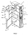
- FIGS 1 to 5 show, according to an embodiment in accordance with the present invention, an electronic box B (also called gateway) that is notably designed to provide an Internet connection to a professional premise, a dwelling, etc.
- the electronic box B is in the shape of a rectangular parallelepiped. Naturally, other shapes (for example oval) can also be envisaged.
- the present invention is in no way limited to an Internet box, but that it can also be applied to a TV decoder box (particularly a set-top box). Moreover, it is clear that the Internet box could have any other shape required and adapted, for example, cubic
- the Internet box B is defined by a depth p, a width l and a length L which extend respectively along directions x, y and z of orthonormal axes (x, y, z) associated with said box B.
- the notions front/back, left/right and top/bottom are defined in relation to the directions x, y and z: the directions of the arrows of the axes (x, y, z) showing, respectively, the passage from back to front, left to right and bottom to top.
- the Internet box B comprises:
- the Internet box B also comprises an auxiliary connection zone 1B arranged on the right-hand lateral face 2A of this one and comprising a plurality of connectors, for example of the type Ethernet, USB, RJ11, etc. as well as a power supply connector.
- the main connection zones 1A and 1B are adjacent and located on the same wall of the box B. It will be understood that, in a variant, they can be arranged on different walls of the Internet box B.
- the main connection zone 1A and the attachment zone 5 are disjointed and distant, as they are arranged respectively on the right-hand lateral face 2A and the front face 6 of the box B, the angle defined between these faces 2A and 6 being a right angle (equal to 90°), or noticeably.
- the Internet box B further comprises a moving cover 10 formed by a flat wall 10A and a cover 10B.
- the cover 10 can occupy at least a closed position ( figures 1 and 4 ) and an open position ( figures 2 and 3 ).
- the passage from the closed position to the open position, and conversely, is shown, symbolically, by the double arrow F0 ( figure 2 ).
- the open position can correspond to a multitude of inclinations of the cover 10, apart from the one associated with the closed position (in which the cover has an angle of 90° wth the direction x).
- the cover 10 By means of a hinge (not shown in the figures) positioned along the left-hand part of the cover 10 on a portion of its length L, the cover 10 is maintained integral with the rest of the box B. It will be understood that, in a variant, the cover can be removable.
- the cover 10B is defined by a first extension 10B.a which extends laterally along the y axis (when the cover 10 occupies the closed position) and a second extension 10B.b extending in depth along the x axis (in the closed position).
- the angle defined between the first and second extensions is a right angle, or noticeably.
- the cover 10B features a profile (defined according to the direction of viewing z) having the shape of an L.
- first and second extensions 10B.a and 10B.b are connected together by an upper linking wall 10B.c.
- a lower linking wall 10B.d connects the lower edges of the first and second extensions 10B.a and 10B.b.
- a cutout 10B.e is made to allow the passage of one or more cables (the connection cable 4 in the example), when the cover 10 occupies the closed position.
- the cover 10B envelops the connection extremity of the cable 4, once the latter is inserted into the connector 3.
- the cover 10 covers the front face 6 of the box B (and thus the attachment zone 5), by means of the flat wall 10A, and some of the right-hand lateral wall 2A (and more specifically the main connection zone 1A, leaving uncovered the auxiliary connection zone 1B), by means of the cover 10B.
- a final user of the box B thus has access to all the connectors of the auxiliary connection zone 1B, independently from the position of the cover 10.
- the cover 10B comprises a wall (in the example the second extension 10B.b) that, when the cover 10 occupies the closed position, is arranged in a plane approximately orthogonal to the direction of insertion and/or removal of the connection cable or cables of the main connection zone 1A (in the example the connection cable 4). In this manner, the removal and/or connection of the cable or cables of the corresponding connectors of the main connection zone 4 is not allowed.
- the second extension 10B.b of the cover 10B is noticeably parallel to the right-hand lateral wall 2A.
- the cover 10B is fitted with a key locking system 11 enabling, in a locked position, the cover 10 to be maintained in the closed position.
- a key locking system 11 enabling, in a locked position, the cover 10 to be maintained in the closed position.
- the locking system 11 is in locked position and the cover 10 in the closed position, the passage of the latter from the closed position to the open position remains impossible.
- any other type of locking system could be envisaged, for example by code.
- the result of the preceding description is that, in the closed position ( figure 1 ), the attachment 5 and main connection 1A zones are simultaneously covered to prevent any access respectively to the screws 7 as well as to the connection cable 4 for an unauthorised person (for example a final user).
- the screws can be replaced by hooks, nails, rivets, etc.
- connection 1A and attachment 5 zones can each be accessed by an operator and/or a final user.
- a rectangular cutout 10C made in the upper right-hand part of the flat wall 10A of the cover 10, enables a multifunction command screen E of the Internet B to be left uncovered in order to make it accessible from the exterior, irrespective of the position (closed or open) occupied by the cover 10.
- the flat wall 10A comprises a peripheral edge 10A.a designed to serve as a barrier to dust to prevent, or at least reduce, the soiling of the Internal box B.
- the peripheral edge 10A.a extends in a direction orthogonal to the plane of the flat wall 10A.
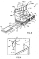
- the Internet box B comprises a slot 12, made at the level of the lower lateral wall 2C and extending in a plane parallel to the latter.
- the slot 12 can have a dust filter 13 that reduces, or even prevents, dust from entering the box B attracted to the latter by internal cooling elements (not shown).
- the lower lateral wall 2C comprises vent holes 14, to enable the ventilated air to circulate from the inside of the box B to the outside and conversely.
- the double arrow F1 ( figure 3 ) shows, symbolically, the direction of insertion and extraction of the filter 13 of the slot 12.
- one or more housings can be arranged in the box B, in its lower part.
- two housings 15 open in the lower lateral wall 2C. They enable the insertion, in the box B, respectively of a hard disk 16 and a CABLECARD card (registered trademark) 17.
- the double arrow F1 shows, symbolically, the direction of insertion and extraction of the hard disk 16 and the card 17.
- the dust filter 13 can be inserted into the associated slot 12. In this manner, as soon as the cover 10 is in the locked closed position, the extraction of the hard disk 16 and the card 17 is no longer allowed. In other words, only an external operator, who has the key controlling the locking and unlocking of the system 11, is capable of extracting the hard disk 16 and the card 17, after first removing the filter 13 from the slot 12 (the cover 10 occupying the open position).
- housings for example to hold a battery
- other housings can be designed in the box B, notably on other walls.
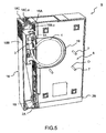
- the box B comprises a removable cable guide 18 designed to orient the cables connected to the main 1A and auxiliary 1B connection zones along the direction z, along the right-hand lateral wall 2A.
- the cable guide 18 is formed by a front wall 18A that extends, when fitted to the box B, in a plane defined by the directions y and z, by a lateral wall 18B extending in a plane defined by the directions x and z, as well as by two upper and lower extremity walls 18C, each belonging to a plane defined by the directions x and y.
- An opening 18C.a is made in each of the extremity walls 18C (only one is shown in figure 5 ) to enable the longitudinal exit for cables crossing the guide 18.
- Each of these openings 18C.a can comprise dust protection means, for example in the form of a row of hairs (or even flexible lips), in order to prevent, or at least limit, the introduction of dust within the cable guide 18 (and thus in the connectors of the main 1A and auxiliary 1B connection zones).
- the cable guide 18 can be fitted to the box B by means of a slider system (not shown in figure 5 ) defined according to the direction x.
- a housing 19 ( figures 2 and 5 ) can be arranged in the rear wall 8 of the box B, in such a manner as to receive a part (preferably rolled) of the connection cable 4 and, possibly, of one or more other cables. This housing is closed by attachment of the box B to the wall 9.
- the moving cover could, in a variant, comprise a flat wall solely designed to cover the attachment zone of the front face, and no longer the latter completely.
- the flat wall of the cover would be in the shape of a strip.
Landscapes
- Engineering & Computer Science (AREA)
- Microelectronics & Electronic Packaging (AREA)
- Theoretical Computer Science (AREA)
- Computer Security & Cryptography (AREA)
- Computer Hardware Design (AREA)
- Power Engineering (AREA)
- Human Computer Interaction (AREA)
- Physics & Mathematics (AREA)
- General Engineering & Computer Science (AREA)
- General Physics & Mathematics (AREA)
- Casings For Electric Apparatus (AREA)
- Connector Housings Or Holding Contact Members (AREA)
Applications Claiming Priority (1)
| Application Number | Priority Date | Filing Date | Title |
|---|---|---|---|
| FR1261965A FR2999371A1 (fr) | 2012-12-12 | 2012-12-12 | Boitier electronique, notamment pour l'acces a internet et/ou pour le decodage video |
Publications (2)
| Publication Number | Publication Date |
|---|---|
| EP2744312A1 EP2744312A1 (en) | 2014-06-18 |
| EP2744312B1 true EP2744312B1 (en) | 2015-07-15 |
Family
ID=47833255
Family Applications (1)
| Application Number | Title | Priority Date | Filing Date |
|---|---|---|---|
| EP13194111.4A Not-in-force EP2744312B1 (en) | 2012-12-12 | 2013-11-22 | Electronic box, particularly for Internet access and/or for video decoding. |
Country Status (7)
Families Citing this family (4)
| Publication number | Priority date | Publication date | Assignee | Title |
|---|---|---|---|---|
| WO2019149596A1 (en) * | 2018-01-30 | 2019-08-08 | Philips Lighting Holding B.V. | A driver housing |
| US11122707B2 (en) | 2018-07-12 | 2021-09-14 | Arris Enterprises Llc | Raised pathway heat sink |
| CN113685092B (zh) * | 2020-05-19 | 2022-09-06 | 富联精密电子(天津)有限公司 | 锁持结构及具有该锁持结构的伺服器机箱 |
| CN115379056B (zh) * | 2022-07-29 | 2025-08-29 | 浙江恒捷通信科技有限公司 | 一种具有电话线路检测功能的语音网关 |
Family Cites Families (15)
| Publication number | Priority date | Publication date | Assignee | Title |
|---|---|---|---|---|
| US5482232A (en) | 1993-06-21 | 1996-01-09 | Mirage Resorts, Incorporated | Apparatus and method for wall-mounted hardware system |
| DE9404470U1 (de) * | 1994-03-16 | 1994-05-11 | Siemens Nixdorf Informationssysteme Ag, 33102 Paderborn | Gehäuse für Datenverarbeitungsgeräte |
| US5823646A (en) * | 1997-09-02 | 1998-10-20 | Siecor Corporation | Door assembly for optical hardware cabinet |
| FR2805357A1 (fr) * | 2000-02-22 | 2001-08-24 | Philippe Jean Jack Gressier | Perfectionnements aux carcasses de micro-ordinateur |
| US6443322B1 (en) * | 2000-10-19 | 2002-09-03 | Fujitsu Network Communications, Inc. | Wall mount enclosure having installation features for multiple separately-installed components |
| JP2005182454A (ja) | 2003-12-19 | 2005-07-07 | Toshiba Corp | 電子機器 |
| CN2715215Y (zh) | 2004-07-02 | 2005-08-03 | 鸿富锦精密工业(深圳)有限公司 | 电脑连接器及线缆保护装置 |
| US7760984B2 (en) * | 2006-05-04 | 2010-07-20 | Adc Telecommunications, Inc. | Fiber distribution hub with swing frame and wrap-around doors |
| US20080120667A1 (en) * | 2006-11-17 | 2008-05-22 | Texas Instruments Incorporated | Hybrid mpeg/ip digital cable gateway device and architecture associated therewith |
| JP2008240439A (ja) | 2007-03-28 | 2008-10-09 | Saxa Inc | 筺体の施錠構造 |
| AU2009213051A1 (en) * | 2008-10-28 | 2010-05-13 | Adc Gmbh | Enclosure for housing splice trays |
| WO2011017486A1 (en) * | 2009-08-07 | 2011-02-10 | Clearone Communications, Inc. | Decoder vesa mounting assembly |
| CN202285424U (zh) * | 2011-10-25 | 2012-06-27 | 四川省迪特尔数字电视有限公司 | 一种支持远程升级和epg节目搜索的iptv机顶盒 |
| US8993886B2 (en) * | 2012-12-10 | 2015-03-31 | Amx Llc | Hardware casing with spring loaded friction fitting cover |
| US20130228368A1 (en) * | 2013-04-19 | 2013-09-05 | Tyco Electronics Raychem Bvba | Wall box and wall mounted plate with integrated ducts |
-
2012
- 2012-12-12 FR FR1261965A patent/FR2999371A1/fr not_active Withdrawn
-
2013
- 2013-11-22 EP EP13194111.4A patent/EP2744312B1/en not_active Not-in-force
- 2013-11-28 BR BRBR102013030720-3A patent/BR102013030720A2/pt not_active Application Discontinuation
- 2013-12-03 CN CN201310644178.5A patent/CN103873898A/zh active Pending
- 2013-12-11 JP JP2013256053A patent/JP2014120169A/ja not_active Withdrawn
- 2013-12-12 KR KR1020130154988A patent/KR20140076523A/ko not_active Withdrawn
- 2013-12-12 US US14/103,913 patent/US9414509B2/en not_active Expired - Fee Related
Also Published As
| Publication number | Publication date |
|---|---|
| JP2014120169A (ja) | 2014-06-30 |
| US20140174817A1 (en) | 2014-06-26 |
| CN103873898A (zh) | 2014-06-18 |
| BR102013030720A2 (pt) | 2014-09-02 |
| FR2999371A1 (fr) | 2014-06-13 |
| KR20140076523A (ko) | 2014-06-20 |
| US9414509B2 (en) | 2016-08-09 |
| EP2744312A1 (en) | 2014-06-18 |
Similar Documents
| Publication | Publication Date | Title |
|---|---|---|
| EP2744312B1 (en) | Electronic box, particularly for Internet access and/or for video decoding. | |
| KR102099072B1 (ko) | 전기 패널용 셔터 도어 조립체 | |
| US7622673B2 (en) | Cable management system | |
| JP5673320B2 (ja) | コネクタ | |
| US11096307B2 (en) | Members and locks for securing devices and/or slots in a computer rack | |
| JP6836889B2 (ja) | 電気接続箱、及び、ワイヤハーネス | |
| RU2562958C2 (ru) | Передняя панель для розетки | |
| US8531828B2 (en) | Storage device carrier having a pivoting panel | |
| US9478956B1 (en) | In use cover for outdoor electrical devices | |
| CA2935842C (en) | Doorless modular panelboard | |
| KR101714425B1 (ko) | Usb 보안장치 | |
| JP2007287492A (ja) | 埋込型電気配線接続装置 | |
| JPH01502154A (ja) | データ通信コネクタの為の壁取付けシステム | |
| KR20180075926A (ko) | 정션 박스 | |
| EP3767766A1 (en) | Electric or electronic device | |
| US6273755B1 (en) | Connector | |
| JP5927650B2 (ja) | 電気機器収納用箱 | |
| US9668365B2 (en) | Lock structure of circuit board unit | |
| JP6224493B2 (ja) | 配電函 | |
| JP2016092087A (ja) | 電気機器収納用箱 | |
| JP4347317B2 (ja) | 機器収容ボックス | |
| KR100721934B1 (ko) | 배선연결이 가능한 건축물 도어구조 | |
| KR20110089969A (ko) | 바나나플러그 접속용 기능성 콘센트 | |
| KR101221042B1 (ko) | 랜선 차단장치 | |
| JP2009224630A (ja) | 電気機器収納箱の連結通線構造 |
Legal Events
| Date | Code | Title | Description |
|---|---|---|---|
| PUAI | Public reference made under article 153(3) epc to a published international application that has entered the european phase |
Free format text: ORIGINAL CODE: 0009012 |
|
| 17P | Request for examination filed |
Effective date: 20131122 |
|
| AK | Designated contracting states |
Kind code of ref document: A1 Designated state(s): AL AT BE BG CH CY CZ DE DK EE ES FI FR GB GR HR HU IE IS IT LI LT LU LV MC MK MT NL NO PL PT RO RS SE SI SK SM TR |
|
| AX | Request for extension of the european patent |
Extension state: BA ME |
|
| R17P | Request for examination filed (corrected) |
Effective date: 20141027 |
|
| RBV | Designated contracting states (corrected) |
Designated state(s): AL AT BE BG CH CY CZ DE DK EE ES FI FR GB GR HR HU IE IS IT LI LT LU LV MC MK MT NL NO PL PT RO RS SE SI SK SM TR |
|
| GRAP | Despatch of communication of intention to grant a patent |
Free format text: ORIGINAL CODE: EPIDOSNIGR1 |
|
| INTG | Intention to grant announced |
Effective date: 20150224 |
|
| GRAP | Despatch of communication of intention to grant a patent |
Free format text: ORIGINAL CODE: EPIDOSNIGR1 |
|
| INTG | Intention to grant announced |
Effective date: 20150508 |
|
| GRAS | Grant fee paid |
Free format text: ORIGINAL CODE: EPIDOSNIGR3 |
|
| GRAA | (expected) grant |
Free format text: ORIGINAL CODE: 0009210 |
|
| AK | Designated contracting states |
Kind code of ref document: B1 Designated state(s): AL AT BE BG CH CY CZ DE DK EE ES FI FR GB GR HR HU IE IS IT LI LT LU LV MC MK MT NL NO PL PT RO RS SE SI SK SM TR |
|
| REG | Reference to a national code |
Ref country code: CH Ref legal event code: EP Ref country code: GB Ref legal event code: FG4D |
|
| REG | Reference to a national code |
Ref country code: IE Ref legal event code: FG4D |
|
| REG | Reference to a national code |
Ref country code: AT Ref legal event code: REF Ref document number: 737320 Country of ref document: AT Kind code of ref document: T Effective date: 20150815 |
|
| REG | Reference to a national code |
Ref country code: DE Ref legal event code: R084 Ref document number: 602013002302 Country of ref document: DE |
|
| REG | Reference to a national code |
Ref country code: GB Ref legal event code: 746 Effective date: 20150803 |
|
| REG | Reference to a national code |
Ref country code: DE Ref legal event code: R096 Ref document number: 602013002302 Country of ref document: DE |
|
| REG | Reference to a national code |
Ref country code: FR Ref legal event code: PLFP Year of fee payment: 3 |
|
| REG | Reference to a national code |
Ref country code: AT Ref legal event code: MK05 Ref document number: 737320 Country of ref document: AT Kind code of ref document: T Effective date: 20150715 |
|
| REG | Reference to a national code |
Ref country code: NL Ref legal event code: MP Effective date: 20150715 |
|
| REG | Reference to a national code |
Ref country code: LT Ref legal event code: MG4D |
|
| PG25 | Lapsed in a contracting state [announced via postgrant information from national office to epo] |
Ref country code: FI Free format text: LAPSE BECAUSE OF FAILURE TO SUBMIT A TRANSLATION OF THE DESCRIPTION OR TO PAY THE FEE WITHIN THE PRESCRIBED TIME-LIMIT Effective date: 20150715 Ref country code: NO Free format text: LAPSE BECAUSE OF FAILURE TO SUBMIT A TRANSLATION OF THE DESCRIPTION OR TO PAY THE FEE WITHIN THE PRESCRIBED TIME-LIMIT Effective date: 20151015 Ref country code: GR Free format text: LAPSE BECAUSE OF FAILURE TO SUBMIT A TRANSLATION OF THE DESCRIPTION OR TO PAY THE FEE WITHIN THE PRESCRIBED TIME-LIMIT Effective date: 20151016 Ref country code: LT Free format text: LAPSE BECAUSE OF FAILURE TO SUBMIT A TRANSLATION OF THE DESCRIPTION OR TO PAY THE FEE WITHIN THE PRESCRIBED TIME-LIMIT Effective date: 20150715 Ref country code: LV Free format text: LAPSE BECAUSE OF FAILURE TO SUBMIT A TRANSLATION OF THE DESCRIPTION OR TO PAY THE FEE WITHIN THE PRESCRIBED TIME-LIMIT Effective date: 20150715 |
|
| PG25 | Lapsed in a contracting state [announced via postgrant information from national office to epo] |
Ref country code: AT Free format text: LAPSE BECAUSE OF FAILURE TO SUBMIT A TRANSLATION OF THE DESCRIPTION OR TO PAY THE FEE WITHIN THE PRESCRIBED TIME-LIMIT Effective date: 20150715 Ref country code: RS Free format text: LAPSE BECAUSE OF FAILURE TO SUBMIT A TRANSLATION OF THE DESCRIPTION OR TO PAY THE FEE WITHIN THE PRESCRIBED TIME-LIMIT Effective date: 20150715 Ref country code: SE Free format text: LAPSE BECAUSE OF FAILURE TO SUBMIT A TRANSLATION OF THE DESCRIPTION OR TO PAY THE FEE WITHIN THE PRESCRIBED TIME-LIMIT Effective date: 20150715 Ref country code: PT Free format text: LAPSE BECAUSE OF FAILURE TO SUBMIT A TRANSLATION OF THE DESCRIPTION OR TO PAY THE FEE WITHIN THE PRESCRIBED TIME-LIMIT Effective date: 20151116 Ref country code: PL Free format text: LAPSE BECAUSE OF FAILURE TO SUBMIT A TRANSLATION OF THE DESCRIPTION OR TO PAY THE FEE WITHIN THE PRESCRIBED TIME-LIMIT Effective date: 20150715 Ref country code: HR Free format text: LAPSE BECAUSE OF FAILURE TO SUBMIT A TRANSLATION OF THE DESCRIPTION OR TO PAY THE FEE WITHIN THE PRESCRIBED TIME-LIMIT Effective date: 20150715 Ref country code: ES Free format text: LAPSE BECAUSE OF FAILURE TO SUBMIT A TRANSLATION OF THE DESCRIPTION OR TO PAY THE FEE WITHIN THE PRESCRIBED TIME-LIMIT Effective date: 20150715 |
|
| REG | Reference to a national code |
Ref country code: DE Ref legal event code: R097 Ref document number: 602013002302 Country of ref document: DE |
|
| PG25 | Lapsed in a contracting state [announced via postgrant information from national office to epo] |
Ref country code: DK Free format text: LAPSE BECAUSE OF FAILURE TO SUBMIT A TRANSLATION OF THE DESCRIPTION OR TO PAY THE FEE WITHIN THE PRESCRIBED TIME-LIMIT Effective date: 20150715 Ref country code: CZ Free format text: LAPSE BECAUSE OF FAILURE TO SUBMIT A TRANSLATION OF THE DESCRIPTION OR TO PAY THE FEE WITHIN THE PRESCRIBED TIME-LIMIT Effective date: 20150715 Ref country code: IT Free format text: LAPSE BECAUSE OF FAILURE TO SUBMIT A TRANSLATION OF THE DESCRIPTION OR TO PAY THE FEE WITHIN THE PRESCRIBED TIME-LIMIT Effective date: 20150715 Ref country code: EE Free format text: LAPSE BECAUSE OF FAILURE TO SUBMIT A TRANSLATION OF THE DESCRIPTION OR TO PAY THE FEE WITHIN THE PRESCRIBED TIME-LIMIT Effective date: 20150715 Ref country code: SK Free format text: LAPSE BECAUSE OF FAILURE TO SUBMIT A TRANSLATION OF THE DESCRIPTION OR TO PAY THE FEE WITHIN THE PRESCRIBED TIME-LIMIT Effective date: 20150715 |
|
| PLBE | No opposition filed within time limit |
Free format text: ORIGINAL CODE: 0009261 |
|
| STAA | Information on the status of an ep patent application or granted ep patent |
Free format text: STATUS: NO OPPOSITION FILED WITHIN TIME LIMIT |
|
| PG25 | Lapsed in a contracting state [announced via postgrant information from national office to epo] |
Ref country code: RO Free format text: LAPSE BECAUSE OF FAILURE TO SUBMIT A TRANSLATION OF THE DESCRIPTION OR TO PAY THE FEE WITHIN THE PRESCRIBED TIME-LIMIT Effective date: 20150715 |
|
| 26N | No opposition filed |
Effective date: 20160418 |
|
| PG25 | Lapsed in a contracting state [announced via postgrant information from national office to epo] |
Ref country code: IS Free format text: LAPSE BECAUSE OF FAILURE TO SUBMIT A TRANSLATION OF THE DESCRIPTION OR TO PAY THE FEE WITHIN THE PRESCRIBED TIME-LIMIT Effective date: 20150715 Ref country code: LU Free format text: LAPSE BECAUSE OF FAILURE TO SUBMIT A TRANSLATION OF THE DESCRIPTION OR TO PAY THE FEE WITHIN THE PRESCRIBED TIME-LIMIT Effective date: 20151122 Ref country code: MC Free format text: LAPSE BECAUSE OF FAILURE TO SUBMIT A TRANSLATION OF THE DESCRIPTION OR TO PAY THE FEE WITHIN THE PRESCRIBED TIME-LIMIT Effective date: 20150715 |
|
| REG | Reference to a national code |
Ref country code: IE Ref legal event code: MM4A |
|
| PG25 | Lapsed in a contracting state [announced via postgrant information from national office to epo] |
Ref country code: SI Free format text: LAPSE BECAUSE OF FAILURE TO SUBMIT A TRANSLATION OF THE DESCRIPTION OR TO PAY THE FEE WITHIN THE PRESCRIBED TIME-LIMIT Effective date: 20150715 |
|
| PG25 | Lapsed in a contracting state [announced via postgrant information from national office to epo] |
Ref country code: IE Free format text: LAPSE BECAUSE OF NON-PAYMENT OF DUE FEES Effective date: 20151122 |
|
| REG | Reference to a national code |
Ref country code: FR Ref legal event code: PLFP Year of fee payment: 4 |
|
| PG25 | Lapsed in a contracting state [announced via postgrant information from national office to epo] |
Ref country code: BE Free format text: LAPSE BECAUSE OF FAILURE TO SUBMIT A TRANSLATION OF THE DESCRIPTION OR TO PAY THE FEE WITHIN THE PRESCRIBED TIME-LIMIT Effective date: 20150715 |
|
| PG25 | Lapsed in a contracting state [announced via postgrant information from national office to epo] |
Ref country code: HU Free format text: LAPSE BECAUSE OF FAILURE TO SUBMIT A TRANSLATION OF THE DESCRIPTION OR TO PAY THE FEE WITHIN THE PRESCRIBED TIME-LIMIT; INVALID AB INITIO Effective date: 20131122 Ref country code: BG Free format text: LAPSE BECAUSE OF FAILURE TO SUBMIT A TRANSLATION OF THE DESCRIPTION OR TO PAY THE FEE WITHIN THE PRESCRIBED TIME-LIMIT Effective date: 20150715 |
|
| PG25 | Lapsed in a contracting state [announced via postgrant information from national office to epo] |
Ref country code: CY Free format text: LAPSE BECAUSE OF FAILURE TO SUBMIT A TRANSLATION OF THE DESCRIPTION OR TO PAY THE FEE WITHIN THE PRESCRIBED TIME-LIMIT Effective date: 20150715 Ref country code: NL Free format text: LAPSE BECAUSE OF FAILURE TO SUBMIT A TRANSLATION OF THE DESCRIPTION OR TO PAY THE FEE WITHIN THE PRESCRIBED TIME-LIMIT Effective date: 20150715 |
|
| REG | Reference to a national code |
Ref country code: CH Ref legal event code: PL |
|
| PG25 | Lapsed in a contracting state [announced via postgrant information from national office to epo] |
Ref country code: CH Free format text: LAPSE BECAUSE OF NON-PAYMENT OF DUE FEES Effective date: 20161130 Ref country code: LI Free format text: LAPSE BECAUSE OF NON-PAYMENT OF DUE FEES Effective date: 20161130 |
|
| REG | Reference to a national code |
Ref country code: DE Ref legal event code: R082 Ref document number: 602013002302 Country of ref document: DE Representative=s name: HOFSTETTER, SCHURACK & PARTNER - PATENT- UND R, DE Ref country code: DE Ref legal event code: R082 Ref document number: 602013002302 Country of ref document: DE Representative=s name: HOFSTETTER, SCHURACK & PARTNER PATENT- UND REC, DE |
|
| PG25 | Lapsed in a contracting state [announced via postgrant information from national office to epo] |
Ref country code: MT Free format text: LAPSE BECAUSE OF FAILURE TO SUBMIT A TRANSLATION OF THE DESCRIPTION OR TO PAY THE FEE WITHIN THE PRESCRIBED TIME-LIMIT Effective date: 20150715 |
|
| REG | Reference to a national code |
Ref country code: FR Ref legal event code: PLFP Year of fee payment: 5 |
|
| PG25 | Lapsed in a contracting state [announced via postgrant information from national office to epo] |
Ref country code: SM Free format text: LAPSE BECAUSE OF FAILURE TO SUBMIT A TRANSLATION OF THE DESCRIPTION OR TO PAY THE FEE WITHIN THE PRESCRIBED TIME-LIMIT Effective date: 20150715 |
|
| PG25 | Lapsed in a contracting state [announced via postgrant information from national office to epo] |
Ref country code: MK Free format text: LAPSE BECAUSE OF FAILURE TO SUBMIT A TRANSLATION OF THE DESCRIPTION OR TO PAY THE FEE WITHIN THE PRESCRIBED TIME-LIMIT Effective date: 20150715 |
|
| PG25 | Lapsed in a contracting state [announced via postgrant information from national office to epo] |
Ref country code: TR Free format text: LAPSE BECAUSE OF FAILURE TO SUBMIT A TRANSLATION OF THE DESCRIPTION OR TO PAY THE FEE WITHIN THE PRESCRIBED TIME-LIMIT Effective date: 20150715 Ref country code: AL Free format text: LAPSE BECAUSE OF FAILURE TO SUBMIT A TRANSLATION OF THE DESCRIPTION OR TO PAY THE FEE WITHIN THE PRESCRIBED TIME-LIMIT Effective date: 20150715 |
|
| PGFP | Annual fee paid to national office [announced via postgrant information from national office to epo] |
Ref country code: DE Payment date: 20191115 Year of fee payment: 7 |
|
| PGFP | Annual fee paid to national office [announced via postgrant information from national office to epo] |
Ref country code: FR Payment date: 20191129 Year of fee payment: 7 |
|
| PGFP | Annual fee paid to national office [announced via postgrant information from national office to epo] |
Ref country code: GB Payment date: 20191122 Year of fee payment: 7 |
|
| REG | Reference to a national code |
Ref country code: DE Ref legal event code: R119 Ref document number: 602013002302 Country of ref document: DE |
|
| GBPC | Gb: european patent ceased through non-payment of renewal fee |
Effective date: 20201122 |
|
| PG25 | Lapsed in a contracting state [announced via postgrant information from national office to epo] |
Ref country code: FR Free format text: LAPSE BECAUSE OF NON-PAYMENT OF DUE FEES Effective date: 20201130 |
|
| PG25 | Lapsed in a contracting state [announced via postgrant information from national office to epo] |
Ref country code: GB Free format text: LAPSE BECAUSE OF NON-PAYMENT OF DUE FEES Effective date: 20201122 Ref country code: DE Free format text: LAPSE BECAUSE OF NON-PAYMENT OF DUE FEES Effective date: 20210601 |