EP2743680A1 - Gas analyzer - Google Patents
Gas analyzer Download PDFInfo
- Publication number
- EP2743680A1 EP2743680A1 EP12823502.5A EP12823502A EP2743680A1 EP 2743680 A1 EP2743680 A1 EP 2743680A1 EP 12823502 A EP12823502 A EP 12823502A EP 2743680 A1 EP2743680 A1 EP 2743680A1
- Authority
- EP
- European Patent Office
- Prior art keywords
- reflector
- light
- gas
- unit
- analysis apparatus
- Prior art date
- Legal status (The legal status is an assumption and is not a legal conclusion. Google has not performed a legal analysis and makes no representation as to the accuracy of the status listed.)
- Granted
Links
Images







Classifications
-
- G—PHYSICS
- G01—MEASURING; TESTING
- G01N—INVESTIGATING OR ANALYSING MATERIALS BY DETERMINING THEIR CHEMICAL OR PHYSICAL PROPERTIES
- G01N21/00—Investigating or analysing materials by the use of optical means, i.e. using sub-millimetre waves, infrared, visible or ultraviolet light
- G01N21/17—Systems in which incident light is modified in accordance with the properties of the material investigated
- G01N21/59—Transmissivity
- G01N21/61—Non-dispersive gas analysers
-
- G—PHYSICS
- G01—MEASURING; TESTING
- G01N—INVESTIGATING OR ANALYSING MATERIALS BY DETERMINING THEIR CHEMICAL OR PHYSICAL PROPERTIES
- G01N21/00—Investigating or analysing materials by the use of optical means, i.e. using sub-millimetre waves, infrared, visible or ultraviolet light
- G01N21/17—Systems in which incident light is modified in accordance with the properties of the material investigated
- G01N21/25—Colour; Spectral properties, i.e. comparison of effect of material on the light at two or more different wavelengths or wavelength bands
- G01N21/27—Colour; Spectral properties, i.e. comparison of effect of material on the light at two or more different wavelengths or wavelength bands using photo-electric detection ; circuits for computing concentration
- G01N21/274—Calibration, base line adjustment, drift correction
-
- G—PHYSICS
- G01—MEASURING; TESTING
- G01N—INVESTIGATING OR ANALYSING MATERIALS BY DETERMINING THEIR CHEMICAL OR PHYSICAL PROPERTIES
- G01N21/00—Investigating or analysing materials by the use of optical means, i.e. using sub-millimetre waves, infrared, visible or ultraviolet light
- G01N21/17—Systems in which incident light is modified in accordance with the properties of the material investigated
- G01N21/25—Colour; Spectral properties, i.e. comparison of effect of material on the light at two or more different wavelengths or wavelength bands
- G01N21/31—Investigating relative effect of material at wavelengths characteristic of specific elements or molecules, e.g. atomic absorption spectrometry
- G01N21/35—Investigating relative effect of material at wavelengths characteristic of specific elements or molecules, e.g. atomic absorption spectrometry using infrared light
- G01N21/3504—Investigating relative effect of material at wavelengths characteristic of specific elements or molecules, e.g. atomic absorption spectrometry using infrared light for analysing gases, e.g. multi-gas analysis
-
- G—PHYSICS
- G01—MEASURING; TESTING
- G01N—INVESTIGATING OR ANALYSING MATERIALS BY DETERMINING THEIR CHEMICAL OR PHYSICAL PROPERTIES
- G01N21/00—Investigating or analysing materials by the use of optical means, i.e. using sub-millimetre waves, infrared, visible or ultraviolet light
- G01N21/17—Systems in which incident light is modified in accordance with the properties of the material investigated
- G01N21/25—Colour; Spectral properties, i.e. comparison of effect of material on the light at two or more different wavelengths or wavelength bands
- G01N21/31—Investigating relative effect of material at wavelengths characteristic of specific elements or molecules, e.g. atomic absorption spectrometry
- G01N21/35—Investigating relative effect of material at wavelengths characteristic of specific elements or molecules, e.g. atomic absorption spectrometry using infrared light
- G01N21/3504—Investigating relative effect of material at wavelengths characteristic of specific elements or molecules, e.g. atomic absorption spectrometry using infrared light for analysing gases, e.g. multi-gas analysis
- G01N2021/3513—Open path with an instrumental source
-
- G—PHYSICS
- G01—MEASURING; TESTING
- G01N—INVESTIGATING OR ANALYSING MATERIALS BY DETERMINING THEIR CHEMICAL OR PHYSICAL PROPERTIES
- G01N21/00—Investigating or analysing materials by the use of optical means, i.e. using sub-millimetre waves, infrared, visible or ultraviolet light
- G01N21/17—Systems in which incident light is modified in accordance with the properties of the material investigated
- G01N21/47—Scattering, i.e. diffuse reflection
- G01N21/49—Scattering, i.e. diffuse reflection within a body or fluid
- G01N21/53—Scattering, i.e. diffuse reflection within a body or fluid within a flowing fluid, e.g. smoke
- G01N21/534—Scattering, i.e. diffuse reflection within a body or fluid within a flowing fluid, e.g. smoke by measuring transmission alone, i.e. determining opacity
- G01N2021/536—Measurement device mounted at stack
-
- G—PHYSICS
- G01—MEASURING; TESTING
- G01N—INVESTIGATING OR ANALYSING MATERIALS BY DETERMINING THEIR CHEMICAL OR PHYSICAL PROPERTIES
- G01N21/00—Investigating or analysing materials by the use of optical means, i.e. using sub-millimetre waves, infrared, visible or ultraviolet light
- G01N21/84—Systems specially adapted for particular applications
- G01N21/85—Investigating moving fluids or granular solids
- G01N21/8507—Probe photometers, i.e. with optical measuring part dipped into fluid sample
- G01N2021/8514—Probe photometers, i.e. with optical measuring part dipped into fluid sample with immersed mirror
-
- G—PHYSICS
- G01—MEASURING; TESTING
- G01N—INVESTIGATING OR ANALYSING MATERIALS BY DETERMINING THEIR CHEMICAL OR PHYSICAL PROPERTIES
- G01N21/00—Investigating or analysing materials by the use of optical means, i.e. using sub-millimetre waves, infrared, visible or ultraviolet light
- G01N21/84—Systems specially adapted for particular applications
- G01N21/85—Investigating moving fluids or granular solids
- G01N2021/8578—Gaseous flow
Definitions
- the present invention relates to a gas analysis apparatus, particularly to a gas analysis apparatus that analyzes concentration of certain components in the sample gas using an optical absorption method.
- exhaust combustion gas which is exhausted from a boiler that burns coal or heavy oil, includes components such as NO x , SO x , CO 2 , and CO.
- a gas analysis apparatus has been developed that analyzes the contents of the components in the gas.
- an apparatus employing probe type has been developed. According to the gas analysis apparatus of probe type, measurement light is emitted from a light source, and the measurement light is reflected by a reflector arranged at a tip end of the probe. The apparatus analyzes constituent concentration of the sample gas based on information on the measurement light reflected by the reflector.
- Some of the conventional gas analysis apparatus of probe type include zero correction function as well as the above-described component concentration analysis function.
- one measurement light which is emitted from the light source, is branched into two beams by an optical coupler and splitter, and one of the beams is used for analyzing the constituent concentration of the gas, and the other of the beams is used for the zero correction.
- the one beam used for analysis on constituent concentration of the gas and the beam used for the zero correction are input into different light receiving units and the signals are processed individually.
- the optical coupler and splitter have wavelength dependence, and cannot output the two beams in the same intensity after branching, depending on the wavelength band.
- the light receiving units have individual differences (differences among the devices) too, and the outputs may be actually different from each other in many cases, even though the light receiving units based on the same design are primarily intended to generate the same outputs in response to the same inputs.
- different signal processing units which receive output from the light receiving unit, are employed for different light receiving units, so that the processing results by the signal processing units have some individual differences.
- Patent Document 1 Furthermore, as a gas analysis apparatus of probe type, one that has calibration function as well as component concentration analysis function is disclosed in Patent Document 1.
- the gas analysis apparatus disclosed in Patent Document 1 includes a probe tube formed with an introduction hole through which the sample gas is introduced. According to the probe tube, most of its parts, including the tip end portion, is positioned inside of a gas flue wall (on a side of the gas flue), and only a base end portion is positioned outside the gas flue wall (on an opposite side of the gas flue). According to this gas analysis apparatus, the measurement light is emitted from the light source positioned outside the gas flue wall toward the sample gas in the probe tube.
- the measurement light is reflected by a first reflector arranged at a tip end portion of the tubular housing, and the reflected measurement light is received by a light receiving sensor arranged outside the gas flue wall. Based on information on the measurement light obtained at the light receiving sensor, the concentration of certain components contained in the sample gas can be calculated.
- This gas analysis apparatus includes, as described above, a function of reflecting the measurement light emitted from the light source at the first reflector and analyzing the constituent concentration of the sample gas.
- the gas analysis apparatus further includes a function of reflecting the measurement light emitted from the light source at the second reflector and calibrating the gas analysis apparatus.
- the second reflector is positioned at a middle portion of the probe tube and inside of the gas flue wall.
- the position of the second reflector can be changed by a switching unit.
- the switching unit is positioned in a middle portion of the probe tube and inside of the gas flue wall, and is configured to move the second reflector out of a light path when analyzing the component concentration and to place the second reflector into the light path when performing the calibration. According to the switching operation by the switching unit, it is possible to selectively perform the analysis of constituent concentration of the gas and the calibration for the gas analysis apparatus.
- Patent Citation US Patent No. 5,781,306
- the present invention was conceived considering the above-described circumstances, it is an object of the present invention to provide an analysis apparatus that is compact and can reduce the manufacturing cost and the maintenance cost, as well as having excellent concentration analysis accuracy.
- a gas analysis apparatus is configured to analyze concentrations of element gases in a sample gas flowing in a flue.
- the gas analysis apparatus includes a light-emitting unit, a first reflector, a light-receiving unit, a second reflector, a known substance containing unit, a computing unit, and a switching unit.
- the light-emitting unit is arranged outside a wall of the flue and configured to apply a measurement light to the sample gas.
- the first reflector is configured to reflect the measurement light applied from the light-emitting unit and that has been transmitted through the sample gas.
- the light-receiving unit is arranged in the vicinity of the light-emitting unit and outside the wall of the flue, and configured to receive the measurement light reflected by the first reflector.
- the second reflector is arranged outside the wall of the flue and configured to reflect the measurement light to the light-receiving unit.
- the known substance containing unit is arranged in a space region along a light path between the light-emitting unit and the second reflector and between the second reflector and the light receiving unit.
- the known substance containing unit contains a known substance that does not attenuate the measurement light emitted from the light-emitting unit or attenuates the measurement light by a predetermined amount.
- the computing unit is configured both to analyze the concentrations of the element gases in the sample gas using the measurement light reflected by the first reflector.
- the computing unit is configured to perform at least one of a correction and a calibration with the known substance using the measurement light reflected by the second reflector.
- the switching unit is arranged outside the wall of the flue and configured to remove the second reflector from the light path when performing the analysis of the concentrations of the element gases and to place the second reflector into the light path when performing at least one of the correction and the calibration.
- known substance can be any substance in which, when applied with the measurement light, the amount of transmitted light is known in advance.
- known substance includes, for example, zero gas and span gas, as well as an optically transparent plate and an optical element which may be optically transparent perfectly for the measurement light or which may limit the transmitted measurement light to a fixed amount.
- correction includes zero correction in which the measurement light is applied by the light emitting unit to the known substance, and the measurement light that has been transmitted through the known substance is received.
- calibration includes zero calibration and span calibration in which the measurement light is applied by the light emitting unit to the known substance, and the measurement light that has been transmitted through the known substance is received.
- does not attenuate the measurement light means that the measurement light is completely transmitted.
- One of the known substances having such characteristics is zero gas, for example.
- the switching operation by the switching unit allows the apparatus to be set selectively in a state of removing the second reflector from the light path or in a state of placing the second reflector into the light path. Accordingly, it is possible to perform the component concentration analysis, the zero correction, the zero calibration, the span calibration, and so on, with one light receiving unit, without allowing one beam to be branched into two light beams by the optical coupler and splitter.
- the switching unit may include a back-forward moving mechanism configured to remove the second reflector from the light path and to place the second reflector into the light path.
- the second reflector when placed in the light path, may serve as a shutter that separates a space near the flue from a space near the known substance containing unit.
- the back-forward moving mechanism may include an air cylinder or a motor.
- the back-forward moving mechanism may include a positioning mechanism configured to arrange the second reflector in a same direction and at a same position every time when the second reflector is placed into the light path through an operation of the air cylinder or the motor.
- the second reflector when the second reflector is returned into the light path by force from the air cylinder or the motor, the second reflector is positioned in the same orientation and at the same position by the positioning mechanism. In this case, the complicated structure for positioning or a special energy source becomes unnecessary, thereby reducing the cost.
- the positioning mechanism may include a holder fixed to the second reflector and a bearing configured to hold the holder.
- the bearing may have a conical concave.
- the holder may have a conical or spherical convex.
- the concave may have a first plane with a trapezoidal shape that is formed in a part of the concave. A side of the first plane at a bottom of the concave may be narrower than that at a top of the concave.
- the convex may have a second plane configured to abut against the first plane in a complementary manner.
- the convex of the holder fits into the concave of the bearing.
- the above-described shape makes it possible for the convex to approach the concave while the convex is allowed to move in the rotational direction.
- the second plane of the convex abuts against the first plane of the concave in a complementary manner.
- the convex can neither move relative to the concave in the moving direction nor in the rotational direction anymore. Accordingly, the second reflector is always positioned in the same direction and at the same position.
- the known substance containing unit may include an optically transparent cell.
- the gas analysis apparatus may further include a probe tube with a cylindrical shape having introduction openings through which the sample gas is introduced into the probe tube.
- the light-emitting unit may apply the measurement light to the sample gas in the probe tube.
- the present invention can be applied to the gas analysis apparatus of probe type, which makes it easier to attach the apparatus to the wall, and to maintain and manage the apparatus.
- the probe tube may include a front end portion placed inside the wall and a base end portion placed outside the wall.
- the first reflector may be arranged at the front end portion of the probe tube, and the second reflector may be arranged at the base end portion of the probe tube.
- the second reflector is positioned at the base end portion of the probe tube (i.e., outside the gas flue wall), when exchanging the second reflectors, it is possible to easily exchange them without extracting the probe from the gas flue.
- the known substance containing unit may be placed at the base end portion of the probe tube.
- the first reflector may be arranged outside the wall that is opposite to a portion where the second reflector is arranged in the flue.
- the present invention can be applied to a gas analysis apparatus of open-path type, in which the first reflector is positioned outside of the wall, on the opposite side of the second reflector in the gas flue.
- the gas analysis apparatus 100 is what is called a gas analysis apparatus of probe type.
- Fig. 1 is an outside view of a gas analysis apparatus according to a first embodiment.
- Fig. 2 is a view including A-A section of the gas analysis apparatus shown in Fig. 1 , and is a view for showing the gas concentration analysis mode.
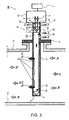
- Fig. 3 is a view including A-A section of the gas analysis apparatus shown in Fig. 1 , and is a view for showing the correction mode or the calibration mode.
- the gas analysis apparatus 100 is a gas analysis apparatus that analyzes concentration of certain components contained in the sample gas flowing into a gas flue 1.
- the gas analysis apparatus 100 is, for example, a non-dispersive infrared (NDIR) analyzer.
- NDIR non-dispersive infrared
- the gas analysis apparatus 100 includes one light emitting unit 2, a first reflector 3, one light receiving unit 4, a second reflector 5, a known substance containing unit 6, a computing unit 7, a switching unit 8, and a probe tube 9.
- the first reflector 3, the second reflector 5, and the known substance containing unit 6 are accommodated in the probe tube 9.
- the light emitting unit 2 and the light receiving unit 4 constitute an optical unit, and are accommodated in a housing 11 of the optical unit.
- an optical window 12 is arranged at a connecting part between the cabinet 11 and the probe tube 9.
- the optical window 12 is a plate member made of materials through which the measurement light Lb may be transmitted.
- the probe tube 9 is a cylindrical member formed with introduction holes 91 for introducing sample gas Sg into the probe tube 9 by diffusion.
- the material of the probe tube 9 can be any metallic materials depending on usage environment of the gas analysis apparatus 100.
- the introduction hole 91 is, as shown in Fig. 1 , for example, continual slits on the side surface of the probe tube 9.
- the first reflector 3 is provided at the tip end portion in the probe tube 9, as shown in Fig. 2 .
- the second reflector 5 and the known substance containing unit 6 are provided.
- the probe tube 9 is fixed to the gas flue wall 1a by means of a flange 15.
- the flange 15 is a member for fixing the gas analysis apparatus 100 to the wall 1a of the gas flue that exhausts the sample gas Sg or a container in which the sample gas Sg is contained with a seal.
- the flange 15 is, for example, a disc-shaped member, and is provided on a side of the probe tube 9 towards the base end portion (a side connected to the optical unit) so as to be penetrated through by the probe tube 9.
- the flange 15 is fastened to the gas flue wall 1a by bolts, for example.
- the portion of the probe tube 9 past the flange 15 towards the tip end is provided inside of the gas flue wall 1a, and the portion of the probe tube 9 towards the base end from the flange 15 is provided outside the gas flue wall 1a.
- Material, shape, and position of the probe tube are not limited.
- position, shape, and the number of the introduction holes formed in the probe tube are not limited.
- the light emitting unit 2 is arranged outside the gas flue wall 1a that constitutes the tubular gas flue 1, and is configured to emit the measurement light Lb into the sample gas Sg flowing through the probe tube 9.
- the light emitting unit 2 is, typically, a light source device that emits light in a certain wavelength region having high rectilinear advancing property, such as an infrared laser oscillating apparatus.
- the first reflector 3 is configured to reflect the measurement light Lb, which has been emitted from the light emitting unit 2 and has been transmitted through the probe tube 9, toward the light receiving unit 4.
- the first reflector 3 is a means for changing the direction of the light (optical axis) emitted from the light emitting unit 2 toward the light receiving unit 4, and is a comer cube, for example. In an example shown in Fig. 2 , it is a comer cube prism. It should be noted that the first reflector 3 may be a corner cube mirror.
- the light receiving unit 4 is arranged in the vicinity of the light emitting unit 2 and outside the gas flue wall 1a.
- the light receiving unit 4 is configured to receive the measurement light Lb that has been reflected by the first reflector 3.
- the light receiving unit 4 is a light receiving device configured to receive the measurement light Lb on a light receiving surface thereof.
- the light receiving unit 4 is typically a photoelectric conversion device such as a photodiode.
- the light receiving unit 4 is electrically connected to the computing unit 7, and is configured to send the information on the received measurement light Lb (e.g., quantity of light) as electric signals to the computing unit 7.
- the second reflector 5 is arranged outside the gas flue wall 1a, and is configured to reflect the measurement light Lb toward the light receiving unit 4.
- the second reflector 5 is a means for changing the direction of the light (optical axis) emitted from the light emitting unit 2 toward the light receiving unit 4, and is a corner cube, for example. In an example shown in Fig. 2 , it is a corner cube prism. It should be noted that the second reflector 5 may be a corner cube mirror.
- the known substance containing unit 6 is arranged at a space region along a light path between the light emitting unit 2 and the second reflector 5 as well as between the second reflector 5 and the light receiving unit 4.
- the known substance containing unit 6 contains a known substance that does not attenuate the measurement light Lb emitted from the light emitting unit 2 or attenuates the measurement light Lb by a predetermined amount.
- "known substance” can be any substance in which, when applied with the measurement light Lb, the amount of transmitted light is known in advance.
- "known substance” includes zero gas and span gas, and further includes an optically transparent plate or an optical element, for example, which may be completely transparent for the measurement light or which may limit the transmitted measurement light to a fixed amount.
- the known substance containing unit 6 is configured to contain a known gas (zero gas or span gas) to correct or calibrate the gas analysis apparatus 100.
- the known substance containing unit 6 can be constituted, for example, by an optically transparent cell 61, a gas introduction pipe 62 for supplying the known gas into the cell 61, and a gas exhaustion pipe 63 for exhausting the known gas in the cell 61.
- "correction” means performing zero correction, for example.
- calibration means performing zero calibration or span calibration, for example.
- the zero gas is a reference gas for correcting the zero point of the gas analysis apparatus 100, and may be nitrogen, for example.
- the structure of the known substance containing unit 6 is not limited to the above-described one.
- the known substance containing unit 6 may be constituted by introducing and filling the known gas into a space region between the optical window 12 and the second reflector 5 while the second reflector 5 is placed in the light path, without providing the optically transparent cell 61, for example.
- the span gas is introduced into the known substance containing unit 6, or the zero gas and the span gas are alternately introduced into the known substance containing unit 6.
- the computing unit 7 (arithmetic processing unit) is configured to control the operation of the light emitting unit 2, the light receiving unit 4, and the switching unit 8. Furthermore, the computing unit 7 is configured to analyze component concentration of the sample gas Sg in the probe tube 9 based on the signals received from the light receiving unit 4 after the measurement light Lb emitted from the light emitting unit 2 is reflected by the first reflector 3. The computing unit 7 is configured to correct or calibrate the gas analysis apparatus 100 using the known gas, by reflecting the measurement light Lb at the second reflector 5 which has been emitted from the light emitting unit 2.
- the computing unit 7 typically includes an information processing unit such as CPU (Central Processing Unit), storage devices such as memory, interface devices for receiving user operations, and a display device for displaying the result of analysis.
- the computing unit 7 performs a computing process based on user operations and programs stored in the storage device.
- the above-described plurality of functions of the computing unit 7 may be realized by a single information processing device, or may be realized by a plurality of information processing units.
- the switching unit 8 is arranged outside the gas flue wall 1a, and is configured to remove the second reflector 5 from the light path when the component concentration is to be analyzed (refer to Figs. 2 , 4 ) and to dispose the second reflector 5 into the light path when the correction or the calibration is to be performed (refer to Figs. 3 , 5 ).
- the structure of the switching unit 8 is not particularly limited, but can be a structure shown in Figs. 4 , 5 , for example.
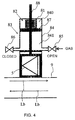
- Fig. 4 is a sectional view showing an example of a structures of the switching unit 8, and is a view for showing the gas concentration analysis mode.
- Fig. 5 is a sectional view for showing an example of structures of the switching unit 8, and is a view for showing the correction mode or the calibration mode.
- the switching unit 8 includes a back-forward moving mechanism configured to remove the second reflector 5 from the light path, and place it into the light path.
- the back-forward moving mechanism includes a spring mechanism 82 configured to place the second reflector 5 into the light path by elastic force of a spring 81, and an air pressure mechanism 83 configured to remove the second reflector 5 from the light path by air pressure while resisting the elastic force of the spring 81.
- the air pressure mechanism 83 includes an air cylinder 84, a supply valve 85, an exhaust valve 86, a piston 87, and a rod 88.
- the air cylinder 84 is provided above the second reflector 5.
- the supply valve 85 supplies the air pressure to the air cylinder 84.
- the exhaust valve 86 exhausts the air in the air cylinder 84.
- the air cylinder 84 has two air chambers with the piston 87 therebetween.
- the first air chamber 840 is defined between an end portion near the base end of the air cylinder 84 and the piston 87, and the spring 81 of compression coil type is arranged in the first air chamber 840. No spring is arranged in a second air chamber 841.
- the supply valve 85 and the exhaust valve 86 are connected to the second air chamber 841, and supply the air to the second air chamber 841 from a compressor, and exhaust the air in the second air chamber 841.
- the air pressure in the second air chamber 841 decreases. If the elastic force of the spring 81 becomes larger than the force by the air pressure, the spring 81 extends and the piston 87 descends. Due to the descending of the piston 87, the second reflector 5 connected to the rod 88 descends, so that the second reflector 5 is placed into the light path. Since the second reflector 5 performs a function of a shutter for blocking the inside of the probe tube 9, it is possible to prevent the sample gas Sg from intruding into a region near the light emitting unit 2.
- the structure of the switching unit 8 can be one shown in Figs. 6 , 7 instead of the above-described one.
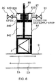
- Fig. 6 is a sectional view for showing another structure of the switching unit 8, and is a view for showing the gas concentration analysis mode.
- Fig. 7 is a sectional view for showing another structure of the switching unit 8, and is a view for showing the correction mode or the calibration mode.
- the switching unit 8 includes a back-forward moving mechanism that removes the second reflector 5 from the light path and places the second reflector 5 into the light path.
- the back-forward moving mechanism includes a spring mechanism 820 configured to remove the second reflector 5 from the light path with an elastic force of the spring 810, and an air pressure mechanism 830 configured to place the second reflector 5 by the air pressure against the elastic force of the spring 810 into the light path.
- the air pressure mechanism 830 includes an air cylinder 84, a supply valve 85, an exhaust valve 86, a piston 87, and a rod 88.
- the air cylinder 84 is provided above the second reflector 5.
- the supply valve 85 is configured to supply the air pressure to the air cylinder 84.
- the exhaust valve 86 is configured to exhaust the air in the air cylinder 84.
- the air cylinder 84 includes two air chambers with the piston 87 therebetween.
- a first air chamber 840 is defined between an end portion near the base end of the air cylinder 84 and the piston 87, and an extension coil spring 810 is arranged in the first air chamber 840. No spring is arranged in a second air chamber 841.
- the supply valve 85 and the exhaust valve 86 are connected to the first air chamber 840, and supply the air from the compressor into the first air chamber 840, and exhaust the air in the first air chamber 840.
- the air from the compressor is supplied through the supply valve 85 to the first air chamber 840.
- the air pressure in the first air chamber 840 increases. If the force by the air pressure becomes larger than the elastic force of the spring 810, the spring 810 extends and the piston 87 descends. Due to the descending of the piston 87, the second reflector 5 connected to the rod 88 descends, so that the second reflector 5 is placed into the light path.
- a purge air introduction port 14 is provided to introduce the purge air Pa into the probe tube 9.
- the purge air introduction port 14 is, as shown in Fig. 2 , provided outside the gas flue wall 1a and on a side of the second reflector 5 near the gas flue, for example.
- the purge air Pa is introduced with a certain pressure to prevent the sample gas Sg and dust in the probe tube 9 from contacting the optical window 12, so that it is possible to reduce contamination and corrosion of the optical window 12.
- an image of the flow path of the purge air Pa is shown with black and bold arrows in Fig. 2
- an image of the flow path of the sample gas Sg is shown with white arrows in Fig. 2 .
- the probe tube 9 includes a purge air introduction pipe 16 configured to introduce the purge air Pa to the front surface of the first reflector 3 for protection. According to this structure, it is possible to prevent the sample gas Sg and the dust in the probe tube 9 from contacting the first reflector 3, so that contamination and corrosion of the first reflector 3 can be reduced.
- the probe tube 9 is formed with holes 17, 18 near two ends, on a side (upstream side of the flow of the sample gas Sg) opposite to the introduction hole 91. Since the sample gas Sg flows through the holes 17, 18, it is possible to prevent the purge air Pa from flowing into the central portion of the probe tube 9, so that the purge air Pa is mixed with the sample gas Sg and then is exhausted from the introduction hole 91 (SgPa).
- the introduction hole 91 is used also as an exhaust port for exhausting the purge air Pa.
- a user gives an instruction to the computing unit 7 for performing the gas concentration analysis. Then, as shown in Figs. 2 , 4 , the switching unit 8 removes the second reflector 5 from the light path of the measurement light Lb emitted from the light emitting unit 2.
- the measurement light Lb emitted from the light emitting unit 2 is transmitted through the sample gas Sg in the probe tube 9, and is reflected by the first reflector 3.
- the reflected measurement light Lb is transmitted through the sample gas Sg again and is received by the light receiving unit 4. Part of the measurement light Lb is absorbed by the sample gas Sg when the measurement light Lb is transmitted through the sample gas Sg.
- the computing unit 7 acquires the amount of absorption of the measurement light Lb in the sample gas Sg, based on difference between information on the measurement light Lb obtained at the light receiving unit 4 and information on of the measurement light Lb when it is emitted from the light emitting unit 2. The computing unit 7 then calculates concentration of certain components contained in the sample gas Sg based on the amount of absorption.
- the correction zero correction
- a user gives an instruction to the computing unit 7 for performing the correction.
- the switching unit 8 places the second reflector 5 into the light path of the measurement light Lb emitted from the light emitting unit 2.
- the measurement light Lb emitted from the light emitting unit 2 is transmitted through the zero gas supplied into the known substance containing unit 6, and is reflected by the second reflector 5.
- the reflected measurement light Lb is transmitted through the zero gas in the known substance containing unit 6 again and is received by the light receiving unit 4.
- the computing unit 7 can calculate a reference value of the zero correction, based on difference between information on the measurement light Lb obtained at the light receiving unit 4 and information on the measurement light Lb when it is emitted from the light emitting unit 2.
- the computing unit 7 performs the zero correction of the gas analysis apparatus 100 using the calculated reference value.
- the zero correction is preferably performed at an interval of one hour, for example.
- the zero correction can be performed each time a user instruction is given, or can be performed automatically and periodically.
- the zero gas and the span gas are alternately supplied into the known substance containing unit 6. Then, as shown in Figs. 3 , 5 , the switching unit 8 places the second reflector 5 into the light path of the measurement light Lb emitted from the light emitting unit 2.
- the measurement light Lb emitted from the light emitting unit 2 is transmitted through the zero gas supplied into the known substance containing unit 6, and is reflected by the second reflector 5.
- the reflected measurement light Lb is transmitted through the zero gas in the known substance containing unit 6 again, and is received by the light receiving unit 4.
- the computing unit 7 calculates a reference value of the zero correction, based on difference between information on the measurement light Lb obtained by the light receiving unit 4 and information on the measurement light Lb emitted from the light emitting unit 2. And, when the span gas is introduced, the measurement light Lb emitted from the light emitting unit 2 is transmitted through the span gas supplied into the known substance containing unit 6, and is reflected by the second reflector 5. Then, the reflected measurement light Lb is transmitted through the span gas in the known substance containing unit 6 again, and is received by the light receiving unit 4. The computing unit 7 calculates a reference value for the span calibration, based on difference between information on the measurement light Lb obtained at the light receiving unit 4 and information on the measurement light Lb when it is emitted from the light emitting unit 2.
- the computing unit 7 performs calibration on the gas analysis apparatus 100 using the respectively calculated reference values when the zero gas is introduced and when the span gas is introduced.
- the calibration can be preferably performed at an interval of one hour, for example.
- the calibration can be performed each time a user instruction is given, or can be performed automatically and periodically.
- the second reflector 5 and the switching unit 8 are arranged outside the gas flue wall 1a, a plurality of effects can be obtained as follows. It should be noted that, it is not necessary to obtain all of the below effects in the first embodiment, but it is sufficient to obtain only one or part of them.
- the back-forward moving mechanism depicted in Figs. 4 , 5 employs a normally closed way. Specifically, when the air pressure is being supplied by the normal operation of the valves 85, 86, the air pressure removes the second reflector 5 from the light path against the elastic force of the spring 81, and the gas analysis apparatus 100 shifts to the gas concentration analysis mode (refer to Fig. 4 ). In contrast, when the supply of the air pressure is being shut off by the normal operation by the valves 85, 86, the elastic force of the spring 81 places the second reflector 5 into the light path, and the gas analysis apparatus 100 shifts to the zero correction mode or calibration mode (refer to Fig. 5 ).
- the elastic force of the spring 81 places the second reflector 5 into the light path, and the gas analysis apparatus 100 shifts to the zero correction mode or calibration mode (refer to Fig. 5 ). Accordingly, during the abnormality such as a power failure, the second reflector 5 performs a shutter function, thereby preventing the sample gas Sg from moving into a space near the light emitting unit 2 and the light receiving unit 4.
- the back-forward moving mechanism depicted in Figs. 6 , 7 employs a normally opened way.
- the air pressure when the air pressure is being supplied by the normal operation of the valves 85, 86, the air pressure places the second reflector 5 into the light path against the elastic force of the spring 810, and the gas analysis apparatus 100 shifts to the correction mode or calibration mode (refer to Fig. 7 ).
- the elastic force of the spring 810 removes the second reflector 5 from the light path, and the gas analysis apparatus 100 shifts to the gas concentration analysis mode (refer to Fig. 6 ).
- the elastic force of the spring 810 removes the second reflector 5 from the light path, and the gas analysis apparatus 100 shifts to the gas concentration analysis mode (refer to Fig. 6 ).
- the gas analysis apparatus 200 is a gas analysis apparatus of what is called open path type.
- Fig. 8 is a sectional view for showing internal constituents of the gas analysis apparatus in the second embodiment, and is a view for showing the gas concentration analysis mode.
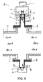
- Fig. 9 is a sectional view for showing internal constituents of the gas analysis apparatus in the second embodiment, and is a view for showing the zero correction mode.
- the second embodiment will be explained by mainly focusing on points different from the first embodiment. The same structure as those of the first embodiment will not be explained, while the same reference symbols are assigned.
- the gas analysis apparatus 200 is constituted by a first unit 19 and a second unit 20, which are formed separately and independently.
- the first unit 19 is attached to one side surface of the wall 1a of the gas flue, through which the sample gas Sg flows, and the second unit 20 is attached to another side surface of the gas flue wall 1a such that the first unit 19 and the second unit 20 face each other.
- the first unit 19 includes a light emitting unit 2, a light receiving unit 4, a second reflector 5, a known substance containing unit 6, a computing unit 7, a switching unit 8, an optical window 12A, and a purge air introduction port 14A.
- the purge air introduction port 14A is configured to introduce purge air Pa into a space connected to the gas flue wall 1a just in front of the second reflector 5.
- the first unit 19 includes a tubular member 114 extending between the flange 15A and the light emitting unit 2 as well as the light receiving unit 4. The tubular member 114 accommodates the known substance containing unit 6 and the switching unit 8.
- the second unit 20 includes the first reflector 3, the optical window 12B, and the purge air introduction port 14B.
- the purge air introduction port 14B introduces purge air Pa into a space connected to the gas flue wall 1a just in front of the optical window 12B.
- a user gives an instruction to the computing unit 7 for performing the gas concentration analysis.
- the switching unit 8 removes the second reflector 5 from the light path of the measurement light Lb emitted from the light emitting unit 2.
- the measurement light Lb emitted from the light emitting unit 2 is transmitted through the sample gas Sg in the gas flue 1, and is reflected by the first reflector 3.
- the reflected measurement light Lb is transmitted through the sample gas Sg in the gas flue 1 again, and is received by the light receiving unit 4.
- part of the measurement light Lb is absorbed by the sample gas Sg.
- the computing unit 7 can acquire the amount of absorption of the measurement light Lb in the sample gas Sg, based on difference between information on the measurement light Lb obtained at the light receiving unit 4 and information on the measurement light Lb when it is emitted from the light emitting unit 2.
- the computing unit 7 can calculate concentration of certain components contained in the sample gas Sg, based on the amount of absorption.
- a user gives an instruction to the computing unit 7 for performing the zero correction.
- the switching unit 8 places the second reflector 5 into the light path of the measurement light Lb emitted from the light emitting unit 2.
- the measurement light Lb emitted from the light emitting unit 2 is transmitted through the zero gas in the known substance containing unit 6, and is reflected by the second reflector 5.
- the reflected measurement light Lb is transmitted through the zero gas in the known substance containing unit 6 again, and is received by the light receiving unit 4.
- the computing unit 7 calculates a reference value of the zero correction, based on difference between information on the measurement light Lb obtained at the light receiving unit 4 and information on the measurement light Lb when it is emitted from the light emitting unit 2.
- the computing unit 7 performs the zero correction of the gas analysis apparatus 200 using the calculated reference value.
- the zero correction can be performed at an interval of one hour, for example. It should be noted that the zero correction can be preferably performed each time a user instruction is given, or can be performed automatically and periodically.
- the known substance containing unit 6 contains the zero gas or the span gas.
- the known substance containing unit 6 may contain an optically transparent plate or an optical element that is perfectly transparent for the measurement light Lb or that limits the transmitted measurement light Lb by a predetermined amount.
- the known substance containing unit 6 is arranged to be fixed in the probe tube 9 or the tubular member 114.
- the known substance containing unit 6 may be configured to be able to move into or out of the probe tube 9 or the tubular member 114.
- the correction or calibration of the analysis apparatus can be performed, and in a state that the known substance containing unit 6 is arranged out of the probe tube 9, the gas concentration analysis can be performed.
- a moving-in-out mechanism for example, the same structure as the above-described back-forward moving mechanism can be employed.
- the known substance containing unit 6 is arranged in the probe tube 9 or the tubular member 114.
- the known substance containing unit 6 may be arranged in the housing 11 of the optical unit or the housing of the first unit 19. In this case, it is possible to make the optical windows 12, 12A and the second reflector 5 close to each other in order to substantially close the gap therebetween.
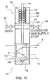
- Fig. 10 is a sectional view for showing a structure of the switching unit in the third embodiment, and is a view for showing the correction mode or the calibration mode.
- Fig. 11 is a perspective view of a bearing.
- Fig. 12 is a plane view of a bearing.
- Fig. 13 is a partial enlarged view of Fig. 10 .
- the second reflector 5 is supported by a mirror holder 104.
- the back-forward moving mechanism includes a positioning mechanism 101.
- the positioning mechanism 101 adjusts the position of the second reflector such that the second reflector 5 has always the same direction and the same position when the air cylinder 84 places the second reflector 5 into the light path.
- the positioning mechanism 101 is arranged below the second reflector 5 and a mirror holder 104, and is composed of a bearing 102, and a convex 103 provided at the mirror holder 104.
- the bearing 102 is, as shown in Fig. 11 , a plate member.
- the bearing 102 is formed with a concave 105 opening upward.
- the concave 105 has a generally conical shape.
- the concave 105 has a conical surface 106.
- the concave 105 is formed with a first plane 107, at a part along the circumferential direction, which extends from a portion inwards of the outer perimeter of the conical surface 106 toward a bottom portion.
- the first plane 107 has a shape of trapezoid whose width becomes narrower toward the bottom portion. It should be noted that an upper edge 107a of the first plane 107 is arranged on a side towards the light emitting unit 2 and the light receiving unit 4, and the upper edge 107a is perpendicular to the light path.
- the convex 103 of the mirror holder 104 is generally spherical.
- the convex 103 has a spherical surface 103a.
- the convex 103 is formed with a second plane 103b along a part in the circumferential direction.
- the second plane 103b is formed in a way as if a part of the spherical surface is cut away toward inside, and its shape and size correspond to those of the first plane 107.
- first plane 107 and the second plane 103b are formed on a side toward which a reflecting surface of the second reflector 5 is desired to face (toward the light emitting unit 2 and the light receiving unit 4, as shown by arrow A).
- the positioning mechanism 101 positions the second reflector 5 in the same orientation and at the same position. Especially, since it is not necessary to have a complicated structure for positioning or a special energy source, the cost is reduced.
- the convex 103 of the mirror holder 104 fits into the concave 105 of the bearing 102.
- the above-described shape allows the convex 103 to move relative to the concave 105 in the vertical direction while being allowed to move in the rotational direction.
- the second plane 103b of the convex 103 abuts against the first plane 107 of the concave 105 in a complementary manner. In this state, the convex 103 can neither move relative to the concave 105 in the moving direction nor the rotational direction. In this way, the second reflector 5 is always positioned in the same orientation and at the same position.
- the positioning mechanism 101 can precisely determine the orientation and the position in the moving direction of the second reflector 5.
- Fig. 14 shows the positioning mechanism 101.
- Fig. 14 is a sectional view of a positioning mechanism, as a first modification of the third embodiment.
- the structure of the concave 105 is the same as that of the above-described embodiment.
- the convex 113 of the mirror holder 104 has a generally conical shape.
- the convex 113 has a conical surface 113a.
- the convex 113 is formed with a second plane 113b along a part in the circumferential direction.
- the second plane 113b is formed in a way as if a part of the conical surface 113a is cut away toward inside, and its shape and size correspond to those of the first plane 107.
- the convex 113 of the mirror holder 104 fits into the concave 105 of the bearing 102.
- the above-described shape allows the convex 113 to move relative to the concave 105 in the vertical direction while being allowed to move relative to the concave 105 in the rotational direction.
- the second plane 113b of the convex 113 abuts against the first plane 107 of the concave 105 in a complementary manner. In this state, the convex 113 can neither move relative to the concave 105 in the moving direction nor the rotational direction. In this way, the second reflector 5 is always positioned in the same direction and at the same position.
- the positioning mechanism 101 can precisely determine the direction and the position in the moving direction of the second reflector 5.
- Fig. 15 shows a bearing 112.
- Fig. 15 is a perspective view of a bearing in a second modification in the third embodiment.
- the bearing 112 is, as shown in Fig. 15 , a plate member.
- the bearing 112 is formed with a concave 115 opening on the upper surface.
- the concave 115 has a generally conical shape.
- the concave 115 has a conical surface 116.
- the concave 115 is formed with a first plane 117, which is formed along a part in the circumferential direction and extends from a part inwards of the outer perimeter of the concave 115 toward the bottom portion.
- the first plane 117 has a shape of trapezoid whose width becomes narrower toward the bottom portion. It should be noted that an upper edge 117a of the first plane 117 is arranged on a side towards the light emitting unit 2 and the light receiving unit 4, and the upper edge 117a is perpendicular to the light path.
- a third plane 118 and a fourth plane 119 are formed on two sides of the first plane 117 in the circumferential direction.
- the third plane 118 and the fourth plane 119 has a shape of trapezoid extending toward the bottom portion, whose width becomes narrower toward the bottom portion, like the first plane 117.
- the circumferential width of the third plane 118 and the fourth plane 119 is narrower than the circumferential width of the first plane 117.
- a convex of the mirror holder has surfaces having a shape that can abut against the first plane 117, the third plane 118, and the fourth plane 119, in a complementary manner.
- the third embodiment can be combined with the first embodiment (including the modifications), or can be combined with the second embodiment (including the modifications).
- the air cylinder is used as a back-forward moving mechanism.
- the back-forward moving mechanism can remove the second reflector from the light path and place second reflector into the light path
- another mechanism can be used.
- the air cylinder instead of the air cylinder, an oil hydraulic cylinder can be used.
- a motor instead of a cylinder, a motor can be employed. In this case, for example, a linear motor or a combination of a rotary motor and a mechanism that converts the rotational force into a force in the straight direction can be used.
- a measurement unit and a gas analysis apparatus according to the present invention can be useful as a measurement unit and a gas analysis apparatus that can analyze the sample gas precisely compared to the conventional ones.
Landscapes
- Physics & Mathematics (AREA)
- Spectroscopy & Molecular Physics (AREA)
- Health & Medical Sciences (AREA)
- Life Sciences & Earth Sciences (AREA)
- Chemical & Material Sciences (AREA)
- Analytical Chemistry (AREA)
- Biochemistry (AREA)
- General Health & Medical Sciences (AREA)
- General Physics & Mathematics (AREA)
- Immunology (AREA)
- Pathology (AREA)
- Engineering & Computer Science (AREA)
- Mathematical Physics (AREA)
- Theoretical Computer Science (AREA)
- Investigating Or Analysing Materials By Optical Means (AREA)
- Sampling And Sample Adjustment (AREA)
Description
- The present invention relates to a gas analysis apparatus, particularly to a gas analysis apparatus that analyzes concentration of certain components in the sample gas using an optical absorption method.
- Conventionally, exhaust combustion gas, which is exhausted from a boiler that burns coal or heavy oil, includes components such as NOx, SOx, CO2, and CO. And a gas analysis apparatus has been developed that analyzes the contents of the components in the gas. As such a gas analysis apparatus, for example, an apparatus employing probe type has been developed. According to the gas analysis apparatus of probe type, measurement light is emitted from a light source, and the measurement light is reflected by a reflector arranged at a tip end of the probe. The apparatus analyzes constituent concentration of the sample gas based on information on the measurement light reflected by the reflector.
- Some of the conventional gas analysis apparatus of probe type include zero correction function as well as the above-described component concentration analysis function. For example, one measurement light, which is emitted from the light source, is branched into two beams by an optical coupler and splitter, and one of the beams is used for analyzing the constituent concentration of the gas, and the other of the beams is used for the zero correction. The one beam used for analysis on constituent concentration of the gas and the beam used for the zero correction are input into different light receiving units and the signals are processed individually.
- However, the above-described gas analysis apparatus includes problems below. The optical coupler and splitter have wavelength dependence, and cannot output the two beams in the same intensity after branching, depending on the wavelength band. In addition, the light receiving units have individual differences (differences among the devices) too, and the outputs may be actually different from each other in many cases, even though the light receiving units based on the same design are primarily intended to generate the same outputs in response to the same inputs. In addition, different signal processing units, which receive output from the light receiving unit, are employed for different light receiving units, so that the processing results by the signal processing units have some individual differences. Accordingly, in the signal processing result obtained based on the above-described two beams after the branch, there is a great chance of a difference resulting from the accumulation of each of the individual differences among the parts. Accordingly, it is impossible to accurately perform the zero correction, so that it is difficult to perform a highly accurate components analysis, which is a problem. Furthermore, it is necessary to have different systems (systems having a light receiving unit and a signal processing unit) for the two beams after the branch, so the whole analysis apparatus has to grow in size. In addition, the heating of the systems increases the heating value of the analysis apparatus as a whole, and the durability of the signal processing circuit is deteriorated, which is a problem. Since the gas analysis apparatus of probe type is attached to the flue for use, it is likely affected by heat of the sample gas and gets higher in temperature, so that it is likely to be deteriorated.
- Furthermore, as a gas analysis apparatus of probe type, one that has calibration function as well as component concentration analysis function is disclosed in
Patent Document 1. The gas analysis apparatus disclosed inPatent Document 1 includes a probe tube formed with an introduction hole through which the sample gas is introduced. According to the probe tube, most of its parts, including the tip end portion, is positioned inside of a gas flue wall (on a side of the gas flue), and only a base end portion is positioned outside the gas flue wall (on an opposite side of the gas flue). According to this gas analysis apparatus, the measurement light is emitted from the light source positioned outside the gas flue wall toward the sample gas in the probe tube. The measurement light is reflected by a first reflector arranged at a tip end portion of the tubular housing, and the reflected measurement light is received by a light receiving sensor arranged outside the gas flue wall. Based on information on the measurement light obtained at the light receiving sensor, the concentration of certain components contained in the sample gas can be calculated. - This gas analysis apparatus includes, as described above, a function of reflecting the measurement light emitted from the light source at the first reflector and analyzing the constituent concentration of the sample gas. The gas analysis apparatus further includes a function of reflecting the measurement light emitted from the light source at the second reflector and calibrating the gas analysis apparatus. The second reflector is positioned at a middle portion of the probe tube and inside of the gas flue wall. The position of the second reflector can be changed by a switching unit. The switching unit is positioned in a middle portion of the probe tube and inside of the gas flue wall, and is configured to move the second reflector out of a light path when analyzing the component concentration and to place the second reflector into the light path when performing the calibration. According to the switching operation by the switching unit, it is possible to selectively perform the analysis of constituent concentration of the gas and the calibration for the gas analysis apparatus.
- Patent Citation:
US Patent No. 5,781,306 - The present invention was conceived considering the above-described circumstances, it is an object of the present invention to provide an analysis apparatus that is compact and can reduce the manufacturing cost and the maintenance cost, as well as having excellent concentration analysis accuracy.
- According to one aspect of the present invention, a gas analysis apparatus is configured to analyze concentrations of element gases in a sample gas flowing in a flue. The gas analysis apparatus includes a light-emitting unit, a first reflector, a light-receiving unit, a second reflector, a known substance containing unit, a computing unit, and a switching unit.
- The light-emitting unit is arranged outside a wall of the flue and configured to apply a measurement light to the sample gas.
- The first reflector is configured to reflect the measurement light applied from the light-emitting unit and that has been transmitted through the sample gas.
- The light-receiving unit is arranged in the vicinity of the light-emitting unit and outside the wall of the flue, and configured to receive the measurement light reflected by the first reflector.
- The second reflector is arranged outside the wall of the flue and configured to reflect the measurement light to the light-receiving unit.
- The known substance containing unit is arranged in a space region along a light path between the light-emitting unit and the second reflector and between the second reflector and the light receiving unit. The known substance containing unit contains a known substance that does not attenuate the measurement light emitted from the light-emitting unit or attenuates the measurement light by a predetermined amount.
- The computing unit is configured both to analyze the concentrations of the element gases in the sample gas using the measurement light reflected by the first reflector. The computing unit is configured to perform at least one of a correction and a calibration with the known substance using the measurement light reflected by the second reflector.
- The switching unit is arranged outside the wall of the flue and configured to remove the second reflector from the light path when performing the analysis of the concentrations of the element gases and to place the second reflector into the light path when performing at least one of the correction and the calibration.
- "Known substance" can be any substance in which, when applied with the measurement light, the amount of transmitted light is known in advance. In other words, "known substance" includes, for example, zero gas and span gas, as well as an optically transparent plate and an optical element which may be optically transparent perfectly for the measurement light or which may limit the transmitted measurement light to a fixed amount.
- Furthermore, "correction" includes zero correction in which the measurement light is applied by the light emitting unit to the known substance, and the measurement light that has been transmitted through the known substance is received. "Calibration" includes zero calibration and span calibration in which the measurement light is applied by the light emitting unit to the known substance, and the measurement light that has been transmitted through the known substance is received.
- In addition, "does not attenuate the measurement light" means that the measurement light is completely transmitted. One of the known substances having such characteristics is zero gas, for example.
- According to this apparatus, since the second reflector and the switching unit are arranged outside the gas flue wall, these parts are not exposed to the sample gas having a high temperature. Accordingly, it is possible to suppress the deterioration of the second reflector and the switching unit, and suppress the frequency of replacing parts, thereby reducing the maintenance cost. In addition, the switching operation by the switching unit allows the apparatus to be set selectively in a state of removing the second reflector from the light path or in a state of placing the second reflector into the light path. Accordingly, it is possible to perform the component concentration analysis, the zero correction, the zero calibration, the span calibration, and so on, with one light receiving unit, without allowing one beam to be branched into two light beams by the optical coupler and splitter. As a result, it is possible to perform the component concentration analysis highly accurately, not being affected by the individual differences due to providing the two light receiving units as in the conventional arts. In addition, it is possible to perform the component concentration analysis, the zero correction, the zero calibration, the span calibration, and so on, with one system (a system consisting of the light receiving unit and the signal processing unit). Accordingly, it is possible to realize a gas analysis apparatus as a whole with small number of parts and to make it compact, thereby suppressing the manufacturing cost. In addition, since the second reflector and the switching unit are arranged outside the gas flue wall, it is easy to exchange these parts.
- The switching unit may include a back-forward moving mechanism configured to remove the second reflector from the light path and to place the second reflector into the light path.
- In this apparatus, by moving the second reflector forward and backward, it is possible to remove the second reflector from the light path, and to place the second reflector into the light path. In other words, it is possible to reliably switch the positions of the second reflector with a simple mechanism.
- The second reflector, when placed in the light path, may serve as a shutter that separates a space near the flue from a space near the known substance containing unit.
- The back-forward moving mechanism may include an air cylinder or a motor.
- The back-forward moving mechanism may include a positioning mechanism configured to arrange the second reflector in a same direction and at a same position every time when the second reflector is placed into the light path through an operation of the air cylinder or the motor.
- In this apparatus, when the second reflector is returned into the light path by force from the air cylinder or the motor, the second reflector is positioned in the same orientation and at the same position by the positioning mechanism. In this case, the complicated structure for positioning or a special energy source becomes unnecessary, thereby reducing the cost.
- The positioning mechanism may include a holder fixed to the second reflector and a bearing configured to hold the holder. The bearing may have a conical concave. The holder may have a conical or spherical convex. The concave may have a first plane with a trapezoidal shape that is formed in a part of the concave. A side of the first plane at a bottom of the concave may be narrower than that at a top of the concave. The convex may have a second plane configured to abut against the first plane in a complementary manner.
- In this apparatus, if the air cylinder or the motor pushes the second reflector and the holder toward the bearing, the convex of the holder fits into the concave of the bearing. At this time, the above-described shape makes it possible for the convex to approach the concave while the convex is allowed to move in the rotational direction. Then, finally, the second plane of the convex abuts against the first plane of the concave in a complementary manner. In this state, the convex can neither move relative to the concave in the moving direction nor in the rotational direction anymore. Accordingly, the second reflector is always positioned in the same direction and at the same position.
- The known substance containing unit may include an optically transparent cell.
- The gas analysis apparatus may further include a probe tube with a cylindrical shape having introduction openings through which the sample gas is introduced into the probe tube. The light-emitting unit may apply the measurement light to the sample gas in the probe tube.
- In this apparatus, the present invention can be applied to the gas analysis apparatus of probe type, which makes it easier to attach the apparatus to the wall, and to maintain and manage the apparatus.
- The probe tube may include a front end portion placed inside the wall and a base end portion placed outside the wall. The first reflector may be arranged at the front end portion of the probe tube, and the second reflector may be arranged at the base end portion of the probe tube.
- In this apparatus, since the second reflector is positioned at the base end portion of the probe tube (i.e., outside the gas flue wall), when exchanging the second reflectors, it is possible to easily exchange them without extracting the probe from the gas flue.
- The known substance containing unit may be placed at the base end portion of the probe tube.
- The first reflector may be arranged outside the wall that is opposite to a portion where the second reflector is arranged in the flue.
- In this apparatus, the present invention can be applied to a gas analysis apparatus of open-path type, in which the first reflector is positioned outside of the wall, on the opposite side of the second reflector in the gas flue.
- According to the present invention, it is possible to provide a gas analysis apparatus, which is compact and can reduce the manufacturing cost and the maintenance cost, and have excellent analytical accuracy.
-
-
Fig. 1 is an outside view of a gas analysis apparatus according to a first embodiment. -
Fig. 2 is a view including A-A section of the gas analysis apparatus shown inFig. 1 , and is a view for showing the gas concentration analysis mode. -
Fig. 3 is a view including A-A section of the gas analysis apparatus shown inFig. 1 , and is a view for showing the correction mode or the calibration mode. -
Fig. 4 is a sectional view showing a structure of a switching unit in the first embodiment, and is a view for showing the gas concentration analysis mode. -
Fig. 5 is a sectional view for showing a structure of the switching unit in the first embodiment, and is a view for showing the correction mode or the calibration mode. -
Fig. 6 is a sectional view for showing another structure of the switching unit in the first embodiment, and is a view for showing the gas concentration analysis mode. -
Fig. 7 is a sectional view for showing another structure of the switching unit in the first embodiment, and is a view for showing the correction mode or the calibration mode. -
Fig. 8 is a sectional view for showing internal constituents of the gas analysis apparatus in the second embodiment, and is a view for showing the gas concentration analysis mode. -
Fig. 9 is a sectional view for showing internal constituents of the gas analysis apparatus in the second embodiment, and is a view for showing the correction mode or the calibration mode. -
Fig. 10 is a sectional view for showing a structure of the switching unit in the third embodiment, and is a view for showing the correction mode or the calibration mode. -
Fig. 11 is a perspective view of a bearing. -
Fig. 12 is a plane view of a bearing. -
Fig. 13 is a partial enlarged view ofFig. 10 . -
Fig. 14 is a sectional view of a positioning mechanism as a first modification of a third embodiment. -
Fig. 15 is a perspective view of a bearing in a second modification in the third embodiment. - Below, a
gas analysis apparatus 100 according to the first embodiment will be described. Thegas analysis apparatus 100 is what is called a gas analysis apparatus of probe type.Fig. 1 is an outside view of a gas analysis apparatus according to a first embodiment.Fig. 2 is a view including A-A section of the gas analysis apparatus shown inFig. 1 , and is a view for showing the gas concentration analysis mode.Fig. 3 is a view including A-A section of the gas analysis apparatus shown inFig. 1 , and is a view for showing the correction mode or the calibration mode. - The
gas analysis apparatus 100 according to the first embodiment is a gas analysis apparatus that analyzes concentration of certain components contained in the sample gas flowing into agas flue 1. Thegas analysis apparatus 100 is, for example, a non-dispersive infrared (NDIR) analyzer. - As shown in
Figs. 2 ,3 , thegas analysis apparatus 100 includes onelight emitting unit 2, afirst reflector 3, onelight receiving unit 4, asecond reflector 5, a known substance containing unit 6, acomputing unit 7, aswitching unit 8, and aprobe tube 9. Thefirst reflector 3, thesecond reflector 5, and the known substance containing unit 6 are accommodated in theprobe tube 9. Thelight emitting unit 2 and thelight receiving unit 4 constitute an optical unit, and are accommodated in ahousing 11 of the optical unit. At a connecting part between thecabinet 11 and theprobe tube 9, anoptical window 12 is arranged. Theoptical window 12 is a plate member made of materials through which the measurement light Lb may be transmitted. - The
probe tube 9 is a cylindrical member formed with introduction holes 91 for introducing sample gas Sg into theprobe tube 9 by diffusion. The material of theprobe tube 9 can be any metallic materials depending on usage environment of thegas analysis apparatus 100. Theintroduction hole 91 is, as shown inFig. 1 , for example, continual slits on the side surface of theprobe tube 9. At the tip end portion in theprobe tube 9, as shown inFig. 2 , thefirst reflector 3 is provided. In contrast, at base end portion in theprobe tube 9, thesecond reflector 5 and the known substance containing unit 6 are provided. - The
probe tube 9 is fixed to thegas flue wall 1a by means of aflange 15. Theflange 15 is a member for fixing thegas analysis apparatus 100 to thewall 1a of the gas flue that exhausts the sample gas Sg or a container in which the sample gas Sg is contained with a seal. Theflange 15 is, for example, a disc-shaped member, and is provided on a side of theprobe tube 9 towards the base end portion (a side connected to the optical unit) so as to be penetrated through by theprobe tube 9. Theflange 15 is fastened to thegas flue wall 1a by bolts, for example. The portion of theprobe tube 9 past theflange 15 towards the tip end is provided inside of thegas flue wall 1a, and the portion of theprobe tube 9 towards the base end from theflange 15 is provided outside thegas flue wall 1a. - Material, shape, and position of the probe tube are not limited. In addition, position, shape, and the number of the introduction holes formed in the probe tube are not limited.
- The
light emitting unit 2 is arranged outside thegas flue wall 1a that constitutes thetubular gas flue 1, and is configured to emit the measurement light Lb into the sample gas Sg flowing through theprobe tube 9. Thelight emitting unit 2 is, typically, a light source device that emits light in a certain wavelength region having high rectilinear advancing property, such as an infrared laser oscillating apparatus. - The
first reflector 3 is configured to reflect the measurement light Lb, which has been emitted from thelight emitting unit 2 and has been transmitted through theprobe tube 9, toward thelight receiving unit 4. In other words, thefirst reflector 3 is a means for changing the direction of the light (optical axis) emitted from thelight emitting unit 2 toward thelight receiving unit 4, and is a comer cube, for example. In an example shown inFig. 2 , it is a comer cube prism. It should be noted that thefirst reflector 3 may be a corner cube mirror. - The
light receiving unit 4 is arranged in the vicinity of thelight emitting unit 2 and outside thegas flue wall 1a. Thelight receiving unit 4 is configured to receive the measurement light Lb that has been reflected by thefirst reflector 3. Thelight receiving unit 4 is a light receiving device configured to receive the measurement light Lb on a light receiving surface thereof. Thelight receiving unit 4 is typically a photoelectric conversion device such as a photodiode. Thelight receiving unit 4 is electrically connected to thecomputing unit 7, and is configured to send the information on the received measurement light Lb (e.g., quantity of light) as electric signals to thecomputing unit 7. - The
second reflector 5 is arranged outside thegas flue wall 1a, and is configured to reflect the measurement light Lb toward thelight receiving unit 4. In other words, thesecond reflector 5 is a means for changing the direction of the light (optical axis) emitted from thelight emitting unit 2 toward thelight receiving unit 4, and is a corner cube, for example. In an example shown inFig. 2 , it is a corner cube prism. It should be noted that thesecond reflector 5 may be a corner cube mirror. - The known substance containing unit 6 is arranged at a space region along a light path between the
light emitting unit 2 and thesecond reflector 5 as well as between thesecond reflector 5 and thelight receiving unit 4. The known substance containing unit 6 contains a known substance that does not attenuate the measurement light Lb emitted from thelight emitting unit 2 or attenuates the measurement light Lb by a predetermined amount. Here, "known substance" can be any substance in which, when applied with the measurement light Lb, the amount of transmitted light is known in advance. In other words, "known substance" includes zero gas and span gas, and further includes an optically transparent plate or an optical element, for example, which may be completely transparent for the measurement light or which may limit the transmitted measurement light to a fixed amount. In an example shown inFigs. 2 ,3 , the known substance containing unit 6 is configured to contain a known gas (zero gas or span gas) to correct or calibrate thegas analysis apparatus 100. The known substance containing unit 6 can be constituted, for example, by an opticallytransparent cell 61, agas introduction pipe 62 for supplying the known gas into thecell 61, and agas exhaustion pipe 63 for exhausting the known gas in thecell 61. In the first embodiment, "correction" means performing zero correction, for example. In addition, "calibration" means performing zero calibration or span calibration, for example. The zero gas is a reference gas for correcting the zero point of thegas analysis apparatus 100, and may be nitrogen, for example. - It should be noted that the structure of the known substance containing unit 6 is not limited to the above-described one. The known substance containing unit 6 may be constituted by introducing and filling the known gas into a space region between the
optical window 12 and thesecond reflector 5 while thesecond reflector 5 is placed in the light path, without providing the opticallytransparent cell 61, for example. When performing the calibration, the span gas is introduced into the known substance containing unit 6, or the zero gas and the span gas are alternately introduced into the known substance containing unit 6. - The computing unit 7 (arithmetic processing unit) is configured to control the operation of the
light emitting unit 2, thelight receiving unit 4, and theswitching unit 8. Furthermore, thecomputing unit 7 is configured to analyze component concentration of the sample gas Sg in theprobe tube 9 based on the signals received from thelight receiving unit 4 after the measurement light Lb emitted from thelight emitting unit 2 is reflected by thefirst reflector 3. Thecomputing unit 7 is configured to correct or calibrate thegas analysis apparatus 100 using the known gas, by reflecting the measurement light Lb at thesecond reflector 5 which has been emitted from thelight emitting unit 2. - The
computing unit 7 typically includes an information processing unit such as CPU (Central Processing Unit), storage devices such as memory, interface devices for receiving user operations, and a display device for displaying the result of analysis. Thecomputing unit 7 performs a computing process based on user operations and programs stored in the storage device. - It should be noted that the above-described plurality of functions of the
computing unit 7 may be realized by a single information processing device, or may be realized by a plurality of information processing units. - The
switching unit 8 is arranged outside thegas flue wall 1a, and is configured to remove thesecond reflector 5 from the light path when the component concentration is to be analyzed (refer toFigs. 2 ,4 ) and to dispose thesecond reflector 5 into the light path when the correction or the calibration is to be performed (refer toFigs. 3 ,5 ). - The structure of the
switching unit 8 is not particularly limited, but can be a structure shown inFigs. 4 ,5 , for example.Fig. 4 is a sectional view showing an example of a structures of theswitching unit 8, and is a view for showing the gas concentration analysis mode.Fig. 5 is a sectional view for showing an example of structures of theswitching unit 8, and is a view for showing the correction mode or the calibration mode. In an example shown inFigs. 4 ,5 , theswitching unit 8 includes a back-forward moving mechanism configured to remove thesecond reflector 5 from the light path, and place it into the light path. The back-forward moving mechanism includes aspring mechanism 82 configured to place thesecond reflector 5 into the light path by elastic force of aspring 81, and anair pressure mechanism 83 configured to remove thesecond reflector 5 from the light path by air pressure while resisting the elastic force of thespring 81. - The
air pressure mechanism 83 includes anair cylinder 84, asupply valve 85, anexhaust valve 86, apiston 87, and arod 88. Theair cylinder 84 is provided above thesecond reflector 5. Thesupply valve 85 supplies the air pressure to theair cylinder 84. Theexhaust valve 86 exhausts the air in theair cylinder 84. Theair cylinder 84 has two air chambers with thepiston 87 therebetween. Thefirst air chamber 840 is defined between an end portion near the base end of theair cylinder 84 and thepiston 87, and thespring 81 of compression coil type is arranged in thefirst air chamber 840. No spring is arranged in asecond air chamber 841. Thesupply valve 85 and theexhaust valve 86 are connected to thesecond air chamber 841, and supply the air to thesecond air chamber 841 from a compressor, and exhaust the air in thesecond air chamber 841. - As shown in
Fig. 4 , when thesupply valve 85 is opened and theexhaust valve 86 is closed, the air flows into thesecond air chamber 841 from the compressor through thesupply valve 85. As a result, the air pressure in thesecond air chamber 841 increases. If the force due to the air pressure becomes higher than the elastic force of thespring 81, thespring 81 is compressed and thepiston 87 ascends. Due to the ascending of thepiston 87, thesecond reflector 5 connected to therod 88 ascends, so that thesecond reflector 5 is removed from the light path. - In contrast, if the
supply valve 85 is closed and theexhaust valve 86 is opened as shown inFig. 5 , the air from the compressor is shut off by thesupply valve 85, so that the air pressure in thesecond air chamber 841 decreases. If the elastic force of thespring 81 becomes larger than the force by the air pressure, thespring 81 extends and thepiston 87 descends. Due to the descending of thepiston 87, thesecond reflector 5 connected to therod 88 descends, so that thesecond reflector 5 is placed into the light path. - Furthermore, as shown in
Fig. 5 , if the air supply from the compressor is shut off due to abnormality such as a power failure, even if thesupply valve 85 is open, the air pressure in thesecond air chamber 841 decreases. If the elastic force of thespring 81 becomes larger than the force by the air pressure, thespring 81 extends and thepiston 87 descends. Due to the descending of thepiston 87, thesecond reflector 5 connected to therod 88 descends, so that thesecond reflector 5 is placed into the light path. Since thesecond reflector 5 performs a function of a shutter for blocking the inside of theprobe tube 9, it is possible to prevent the sample gas Sg from intruding into a region near thelight emitting unit 2. - Since it is essential only that the
switching unit 8 is arranged outside thegas flue wall 1a, various modifications can be employed. For example, the structure of theswitching unit 8 can be one shown inFigs. 6 ,7 instead of the above-described one.Fig. 6 is a sectional view for showing another structure of theswitching unit 8, and is a view for showing the gas concentration analysis mode.Fig. 7 is a sectional view for showing another structure of theswitching unit 8, and is a view for showing the correction mode or the calibration mode. According to the example shown inFigs. 6 ,7 , theswitching unit 8 includes a back-forward moving mechanism that removes thesecond reflector 5 from the light path and places thesecond reflector 5 into the light path. The back-forward moving mechanism includes aspring mechanism 820 configured to remove thesecond reflector 5 from the light path with an elastic force of thespring 810, and anair pressure mechanism 830 configured to place thesecond reflector 5 by the air pressure against the elastic force of thespring 810 into the light path. - The
air pressure mechanism 830 includes anair cylinder 84, asupply valve 85, anexhaust valve 86, apiston 87, and arod 88. Theair cylinder 84 is provided above thesecond reflector 5. Thesupply valve 85 is configured to supply the air pressure to theair cylinder 84. Theexhaust valve 86 is configured to exhaust the air in theair cylinder 84. Theair cylinder 84 includes two air chambers with thepiston 87 therebetween. Afirst air chamber 840 is defined between an end portion near the base end of theair cylinder 84 and thepiston 87, and anextension coil spring 810 is arranged in thefirst air chamber 840. No spring is arranged in asecond air chamber 841. Thesupply valve 85 and theexhaust valve 86 are connected to thefirst air chamber 840, and supply the air from the compressor into thefirst air chamber 840, and exhaust the air in thefirst air chamber 840. - As shown in
Fig. 6 , if thesupply valve 85 is closed and theexhaust valve 86 is opened, the air from the compressor is shut off by thesupply valve 85, so that the air pressure in thefirst air chamber 840 decreases. If the elastic force of thespring 810 becomes larger than the force by the air pressure, thespring 810 is contracted and thepiston 87 ascends. Due to the ascending of thepiston 87, thesecond reflector 5 connected to therod 88 ascends, so that thesecond reflector 5 is removed from the light path. - In addition, as shown in
Fig. 6 , if the supply of the air from the compressor is shut off due to abnormality such as a power failure, even if thesupply valve 85 is open, the air pressure in thefirst air chamber 840 decreases. If the elastic force of thespring 810 becomes larger than the force by the air pressure, thespring 810 is contracted and thepiston 87 ascends. Due to the ascending of thepiston 87, thesecond reflector 5 connected to therod 88 ascends, and thesecond reflector 5 is removed from the light path. - In contrast, if the
supply valve 85 is opened and theexhaust valve 86 is closed as shown inFig. 7 , the air from the compressor is supplied through thesupply valve 85 to thefirst air chamber 840. As a result, the air pressure in thefirst air chamber 840 increases. If the force by the air pressure becomes larger than the elastic force of thespring 810, thespring 810 extends and thepiston 87 descends. Due to the descending of thepiston 87, thesecond reflector 5 connected to therod 88 descends, so that thesecond reflector 5 is placed into the light path. - In the above-described
probe tube 9, as shown inFig. 2 , a purgeair introduction port 14 is provided to introduce the purge air Pa into theprobe tube 9. The purgeair introduction port 14 is, as shown inFig. 2 , provided outside thegas flue wall 1a and on a side of thesecond reflector 5 near the gas flue, for example. Through the purgeair introduction port 14 arranged as previously mentioned, the purge air Pa is introduced with a certain pressure to prevent the sample gas Sg and dust in theprobe tube 9 from contacting theoptical window 12, so that it is possible to reduce contamination and corrosion of theoptical window 12. It should be noted that an image of the flow path of the purge air Pa is shown with black and bold arrows inFig. 2 , and an image of the flow path of the sample gas Sg is shown with white arrows inFig. 2 . - Furthermore, the
probe tube 9 includes a purgeair introduction pipe 16 configured to introduce the purge air Pa to the front surface of thefirst reflector 3 for protection. According to this structure, it is possible to prevent the sample gas Sg and the dust in theprobe tube 9 from contacting thefirst reflector 3, so that contamination and corrosion of thefirst reflector 3 can be reduced. - In addition, as shown in
Fig. 2 , theprobe tube 9 is formed withholes introduction hole 91. Since the sample gas Sg flows through theholes probe tube 9, so that the purge air Pa is mixed with the sample gas Sg and then is exhausted from the introduction hole 91 (SgPa). Theintroduction hole 91 is used also as an exhaust port for exhausting the purge air Pa. - Next, use of the
gas analysis apparatus 100 will be described. - First, a case will be explained in which a normal gas concentration analysis is performed.
- A user gives an instruction to the
computing unit 7 for performing the gas concentration analysis. Then, as shown inFigs. 2 ,4 , theswitching unit 8 removes thesecond reflector 5 from the light path of the measurement light Lb emitted from thelight emitting unit 2. The measurement light Lb emitted from thelight emitting unit 2 is transmitted through the sample gas Sg in theprobe tube 9, and is reflected by thefirst reflector 3. The reflected measurement light Lb is transmitted through the sample gas Sg again and is received by thelight receiving unit 4. Part of the measurement light Lb is absorbed by the sample gas Sg when the measurement light Lb is transmitted through the sample gas Sg. Thecomputing unit 7 acquires the amount of absorption of the measurement light Lb in the sample gas Sg, based on difference between information on the measurement light Lb obtained at thelight receiving unit 4 and information on of the measurement light Lb when it is emitted from thelight emitting unit 2. Thecomputing unit 7 then calculates concentration of certain components contained in the sample gas Sg based on the amount of absorption. - Next, a case will be explained in which the correction (zero correction) is performed. A user gives an instruction to the
computing unit 7 for performing the correction. Then, as shown inFigs. 3 ,5 , theswitching unit 8 places thesecond reflector 5 into the light path of the measurement light Lb emitted from thelight emitting unit 2. The measurement light Lb emitted from thelight emitting unit 2 is transmitted through the zero gas supplied into the known substance containing unit 6, and is reflected by thesecond reflector 5. The reflected measurement light Lb is transmitted through the zero gas in the known substance containing unit 6 again and is received by thelight receiving unit 4. Thecomputing unit 7 can calculate a reference value of the zero correction, based on difference between information on the measurement light Lb obtained at thelight receiving unit 4 and information on the measurement light Lb when it is emitted from thelight emitting unit 2. Thecomputing unit 7 performs the zero correction of thegas analysis apparatus 100 using the calculated reference value. The zero correction is preferably performed at an interval of one hour, for example. The zero correction can be performed each time a user instruction is given, or can be performed automatically and periodically. - Next, a case is explained in which the calibration is performed. Here, an example will be explained in which both the zero correction and the span calibration are performed.
- In order to perform the zero correction and the span calibration, the zero gas and the span gas are alternately supplied into the known substance containing unit 6. Then, as shown in
Figs. 3 ,5 , theswitching unit 8 places thesecond reflector 5 into the light path of the measurement light Lb emitted from thelight emitting unit 2. When the zero gas is introduced, the measurement light Lb emitted from thelight emitting unit 2 is transmitted through the zero gas supplied into the known substance containing unit 6, and is reflected by thesecond reflector 5. The reflected measurement light Lb is transmitted through the zero gas in the known substance containing unit 6 again, and is received by thelight receiving unit 4. Thecomputing unit 7 calculates a reference value of the zero correction, based on difference between information on the measurement light Lb obtained by thelight receiving unit 4 and information on the measurement light Lb emitted from thelight emitting unit 2. And, when the span gas is introduced, the measurement light Lb emitted from thelight emitting unit 2 is transmitted through the span gas supplied into the known substance containing unit 6, and is reflected by thesecond reflector 5. Then, the reflected measurement light Lb is transmitted through the span gas in the known substance containing unit 6 again, and is received by thelight receiving unit 4. Thecomputing unit 7 calculates a reference value for the span calibration, based on difference between information on the measurement light Lb obtained at thelight receiving unit 4 and information on the measurement light Lb when it is emitted from thelight emitting unit 2. Thecomputing unit 7 performs calibration on thegas analysis apparatus 100 using the respectively calculated reference values when the zero gas is introduced and when the span gas is introduced. The calibration can be preferably performed at an interval of one hour, for example. The calibration can be performed each time a user instruction is given, or can be performed automatically and periodically. - According to the first embodiment, since the
second reflector 5 and theswitching unit 8 are arranged outside thegas flue wall 1a, a plurality of effects can be obtained as follows. It should be noted that, it is not necessary to obtain all of the below effects in the first embodiment, but it is sufficient to obtain only one or part of them. - 1) The
second reflector 5 and theswitching unit 8 are not exposed to the sample gas Sg, which has a high temperature. Accordingly, it is possible to suppress the deterioration of thesecond reflector 5 and theswitching unit 8, thereby reducing the frequency of replacing parts and thereby reducing the maintenance cost. It should be noted that in the present invention, in order to highly precisely perform the component concentration analysis (sampling), at least one of the correction or the calibration is performed. It is not necessary to set the temperature of the zero gas used for the correction to the same level as the temperature of the analysis target gas (i.e., the zero gas does not substantially absorb the measurement light regardless of the temperature). Accordingly, in this embodiment, it is possible to arrange the known substance containing unit 6 with thesecond reflector 5 outside thegas flue wall 1a. It should be noted that even if the known substance containing unit 6 is arranged with thesecond reflector 5 outside thegas flue wall 1a, it is possible to perform the calibration as described above. - 2) The switching operation of the
switching unit 8 makes it possible to selectively set a state in which thesecond reflector 5 is removed from the light path and a state in which thesecond reflector 5 is placed into the light path. Accordingly, it is possible to perform the component concentration analysis, the zero correction, the zero calibration, and the span calibration with onelight receiving unit 4, without using the optical coupler and splitter for branching the one light beam into two light beams. As a result, it is possible to highly precisely perform the component concentration analysis without the effects from individual differences due to having two light receiving units, as in the conventional arts. - 3) With one system (the system consisting of the
light receiving unit 4 and the computing unit 7), it is possible to perform the component concentration analysis, the zero correction, the zero calibration, and the span calibration. Accordingly, it is possible to make thegas analysis apparatus 100, as a whole, compact with small number of parts, thereby reducing the manufacturing cost. - 4) Since the
second reflector 5 and theswitching unit 8 are arranged outside thegas flue wall 1a, it is possible to exchange these parts easily. - Furthermore, the back-forward moving mechanism depicted in
Figs. 4 ,5 employs a normally closed way. Specifically, when the air pressure is being supplied by the normal operation of thevalves second reflector 5 from the light path against the elastic force of thespring 81, and thegas analysis apparatus 100 shifts to the gas concentration analysis mode (refer toFig. 4 ). In contrast, when the supply of the air pressure is being shut off by the normal operation by thevalves spring 81 places thesecond reflector 5 into the light path, and thegas analysis apparatus 100 shifts to the zero correction mode or calibration mode (refer toFig. 5 ). Furthermore, when the supply of the air pressure is being shut off due to abnormality such as a power failure, the elastic force of thespring 81 places thesecond reflector 5 into the light path, and thegas analysis apparatus 100 shifts to the zero correction mode or calibration mode (refer toFig. 5 ). Accordingly, during the abnormality such as a power failure, thesecond reflector 5 performs a shutter function, thereby preventing the sample gas Sg from moving into a space near thelight emitting unit 2 and thelight receiving unit 4. - In addition, the back-forward moving mechanism depicted in
Figs. 6 ,7 employs a normally opened way. In other words, when the air pressure is being supplied by the normal operation of thevalves second reflector 5 into the light path against the elastic force of thespring 810, and thegas analysis apparatus 100 shifts to the correction mode or calibration mode (refer toFig. 7 ). In contrast, when the supply of the air pressure is being shut off by the normal operation of thevalves spring 810 removes thesecond reflector 5 from the light path, and thegas analysis apparatus 100 shifts to the gas concentration analysis mode (refer toFig. 6 ). In addition, when the supply of the air pressure is being shut off due to abnormality such as a power failure, the elastic force of thespring 810 removes thesecond reflector 5 from the light path, and thegas analysis apparatus 100 shifts to the gas concentration analysis mode (refer toFig. 6 ). - Below, a
gas analysis apparatus 200 according to the second embodiment will be described. Thegas analysis apparatus 200 is a gas analysis apparatus of what is called open path type.Fig. 8 is a sectional view for showing internal constituents of the gas analysis apparatus in the second embodiment, and is a view for showing the gas concentration analysis mode.Fig. 9 is a sectional view for showing internal constituents of the gas analysis apparatus in the second embodiment, and is a view for showing the zero correction mode. The second embodiment will be explained by mainly focusing on points different from the first embodiment. The same structure as those of the first embodiment will not be explained, while the same reference symbols are assigned. - According to the second embodiment, as shown in
Figs. 8 ,9 , thegas analysis apparatus 200 is constituted by afirst unit 19 and asecond unit 20, which are formed separately and independently. Thefirst unit 19 is attached to one side surface of thewall 1a of the gas flue, through which the sample gas Sg flows, and thesecond unit 20 is attached to another side surface of thegas flue wall 1a such that thefirst unit 19 and thesecond unit 20 face each other. - The
first unit 19 includes alight emitting unit 2, alight receiving unit 4, asecond reflector 5, a known substance containing unit 6, acomputing unit 7, aswitching unit 8, anoptical window 12A, and a purgeair introduction port 14A. The purgeair introduction port 14A is configured to introduce purge air Pa into a space connected to thegas flue wall 1a just in front of thesecond reflector 5. Thefirst unit 19 includes a tubular member 114 extending between theflange 15A and thelight emitting unit 2 as well as thelight receiving unit 4. The tubular member 114 accommodates the known substance containing unit 6 and theswitching unit 8. - The
second unit 20 includes thefirst reflector 3, theoptical window 12B, and the purgeair introduction port 14B. The purgeair introduction port 14B introduces purge air Pa into a space connected to thegas flue wall 1a just in front of theoptical window 12B. - Next, use of the
gas analysis apparatus 200 will be described. - First, a case will be described in which a normal gas concentration analysis is performed.
- A user gives an instruction to the
computing unit 7 for performing the gas concentration analysis. Then, as shown inFig. 8 , theswitching unit 8 removes thesecond reflector 5 from the light path of the measurement light Lb emitted from thelight emitting unit 2. The measurement light Lb emitted from thelight emitting unit 2 is transmitted through the sample gas Sg in thegas flue 1, and is reflected by thefirst reflector 3. The reflected measurement light Lb is transmitted through the sample gas Sg in thegas flue 1 again, and is received by thelight receiving unit 4. When the measurement light Lb is transmitted through the sample gas Sg, part of the measurement light Lb is absorbed by the sample gas Sg. Thecomputing unit 7 can acquire the amount of absorption of the measurement light Lb in the sample gas Sg, based on difference between information on the measurement light Lb obtained at thelight receiving unit 4 and information on the measurement light Lb when it is emitted from thelight emitting unit 2. Thecomputing unit 7 can calculate concentration of certain components contained in the sample gas Sg, based on the amount of absorption. - Next, a case will be described in which the zero correction is performed.
- A user gives an instruction to the
computing unit 7 for performing the zero correction. Then, as shown inFig. 9 , theswitching unit 8 places thesecond reflector 5 into the light path of the measurement light Lb emitted from thelight emitting unit 2. The measurement light Lb emitted from thelight emitting unit 2 is transmitted through the zero gas in the known substance containing unit 6, and is reflected by thesecond reflector 5. The reflected measurement light Lb is transmitted through the zero gas in the known substance containing unit 6 again, and is received by thelight receiving unit 4. Thecomputing unit 7 calculates a reference value of the zero correction, based on difference between information on the measurement light Lb obtained at thelight receiving unit 4 and information on the measurement light Lb when it is emitted from thelight emitting unit 2. Thecomputing unit 7 performs the zero correction of thegas analysis apparatus 200 using the calculated reference value. The zero correction can be performed at an interval of one hour, for example. It should be noted that the zero correction can be preferably performed each time a user instruction is given, or can be performed automatically and periodically. - In the second embodiment too, since the
second reflector 5 and theswitching unit 8 are arranged outside thegas flue wall 1a, the same excellent effects are achieved as in the first embodiment. - Since the known substance containing unit 6 just has to be arranged outside the
gas flue wall 1a, various modifications are possible. Below, those modifications will be explained. - In the above-described embodiments, the known substance containing unit 6 contains the zero gas or the span gas. However, instead of these, the known substance containing unit 6 may contain an optically transparent plate or an optical element that is perfectly transparent for the measurement light Lb or that limits the transmitted measurement light Lb by a predetermined amount.
- In addition, in the above-described embodiment, the known substance containing unit 6 is arranged to be fixed in the
probe tube 9 or the tubular member 114. However, instead of these, the known substance containing unit 6 may be configured to be able to move into or out of theprobe tube 9 or the tubular member 114. In this case, in a state that the known substance containing unit 6 is arranged in theprobe tube 9 or the tubular member 114, the correction or calibration of the analysis apparatus can be performed, and in a state that the known substance containing unit 6 is arranged out of theprobe tube 9, the gas concentration analysis can be performed. As a moving-in-out mechanism, for example, the same structure as the above-described back-forward moving mechanism can be employed. - Furthermore, in the above-described embodiments, the known substance containing unit 6 is arranged in the
probe tube 9 or the tubular member 114. However, instead of these, the known substance containing unit 6 may be arranged in thehousing 11 of the optical unit or the housing of thefirst unit 19. In this case, it is possible to make theoptical windows second reflector 5 close to each other in order to substantially close the gap therebetween. - Using
Fig. 10 to Fig. 13 , a third embodiment will be described. The third embodiment is different from the above-described embodiments only in a structure that supports thesecond reflector 5.Fig. 10 is a sectional view for showing a structure of the switching unit in the third embodiment, and is a view for showing the correction mode or the calibration mode.Fig. 11 is a perspective view of a bearing.Fig. 12 is a plane view of a bearing.Fig. 13 is a partial enlarged view ofFig. 10 . - The
second reflector 5 is supported by amirror holder 104. - As shown in
Fig. 10 , in this embodiment, the back-forward moving mechanism includes apositioning mechanism 101. Thepositioning mechanism 101 adjusts the position of the second reflector such that thesecond reflector 5 has always the same direction and the same position when theair cylinder 84 places thesecond reflector 5 into the light path. - The
positioning mechanism 101 is arranged below thesecond reflector 5 and amirror holder 104, and is composed of abearing 102, and a convex 103 provided at themirror holder 104. - The
bearing 102 is, as shown inFig. 11 , a plate member. Thebearing 102 is formed with a concave 105 opening upward. The concave 105 has a generally conical shape. The concave 105 has aconical surface 106. The concave 105 is formed with afirst plane 107, at a part along the circumferential direction, which extends from a portion inwards of the outer perimeter of theconical surface 106 toward a bottom portion. Thefirst plane 107 has a shape of trapezoid whose width becomes narrower toward the bottom portion. It should be noted that anupper edge 107a of thefirst plane 107 is arranged on a side towards thelight emitting unit 2 and thelight receiving unit 4, and theupper edge 107a is perpendicular to the light path. - The convex 103 of the
mirror holder 104 is generally spherical. The convex 103 has aspherical surface 103a. In addition, the convex 103 is formed with asecond plane 103b along a part in the circumferential direction. Thesecond plane 103b is formed in a way as if a part of the spherical surface is cut away toward inside, and its shape and size correspond to those of thefirst plane 107. - It should be noted that the
first plane 107 and thesecond plane 103b are formed on a side toward which a reflecting surface of thesecond reflector 5 is desired to face (toward thelight emitting unit 2 and thelight receiving unit 4, as shown by arrow A). - In this apparatus, when the
second reflector 5 is returned into the light path by the force from theair cylinder 84, thepositioning mechanism 101 positions thesecond reflector 5 in the same orientation and at the same position. Especially, since it is not necessary to have a complicated structure for positioning or a special energy source, the cost is reduced. - More specifically, if the
air cylinder 84 pushes thesecond reflector 5 and themirror holder 104 toward thebearing 102, the convex 103 of themirror holder 104 fits into the concave 105 of thebearing 102. At this time, the above-described shape allows the convex 103 to move relative to the concave 105 in the vertical direction while being allowed to move in the rotational direction. Finally, thesecond plane 103b of the convex 103 abuts against thefirst plane 107 of the concave 105 in a complementary manner. In this state, the convex 103 can neither move relative to the concave 105 in the moving direction nor the rotational direction. In this way, thesecond reflector 5 is always positioned in the same orientation and at the same position. - Particularly, only by the operation of the
air cylinder 84 pressing thesecond reflector 5, thepositioning mechanism 101 can precisely determine the orientation and the position in the moving direction of thesecond reflector 5. - As a first modification of the third embodiment,
Fig. 14 shows thepositioning mechanism 101.Fig. 14 is a sectional view of a positioning mechanism, as a first modification of the third embodiment. - The structure of the concave 105 is the same as that of the above-described embodiment.
- The convex 113 of the
mirror holder 104 has a generally conical shape. The convex 113 has aconical surface 113a. In addition, the convex 113 is formed with asecond plane 113b along a part in the circumferential direction. Thesecond plane 113b is formed in a way as if a part of theconical surface 113a is cut away toward inside, and its shape and size correspond to those of thefirst plane 107. - If the
air cylinder 84 pushes thesecond reflector 5 and themirror holder 104 toward thebearing 102, the convex 113 of themirror holder 104 fits into the concave 105 of thebearing 102. At this time, the above-described shape allows the convex 113 to move relative to the concave 105 in the vertical direction while being allowed to move relative to the concave 105 in the rotational direction. Finally, thesecond plane 113b of the convex 113 abuts against thefirst plane 107 of the concave 105 in a complementary manner. In this state, the convex 113 can neither move relative to the concave 105 in the moving direction nor the rotational direction. In this way, thesecond reflector 5 is always positioned in the same direction and at the same position. - Particularly, by only the operation of the
air cylinder 84 pressing thesecond reflector 5, thepositioning mechanism 101 can precisely determine the direction and the position in the moving direction of thesecond reflector 5. - As a second modification of the third embodiment,
Fig. 15 shows abearing 112.Fig. 15 is a perspective view of a bearing in a second modification in the third embodiment. - The
bearing 112 is, as shown inFig. 15 , a plate member. Thebearing 112 is formed with a concave 115 opening on the upper surface. The concave 115 has a generally conical shape. The concave 115 has aconical surface 116. The concave 115 is formed with afirst plane 117, which is formed along a part in the circumferential direction and extends from a part inwards of the outer perimeter of the concave 115 toward the bottom portion. Thefirst plane 117 has a shape of trapezoid whose width becomes narrower toward the bottom portion. It should be noted that anupper edge 117a of thefirst plane 117 is arranged on a side towards thelight emitting unit 2 and thelight receiving unit 4, and theupper edge 117a is perpendicular to the light path. - In this modification, a
third plane 118 and afourth plane 119 are formed on two sides of thefirst plane 117 in the circumferential direction. Thethird plane 118 and thefourth plane 119 has a shape of trapezoid extending toward the bottom portion, whose width becomes narrower toward the bottom portion, like thefirst plane 117. However, the circumferential width of thethird plane 118 and thefourth plane 119 is narrower than the circumferential width of thefirst plane 117. - Although not shown in the figures, a convex of the mirror holder has surfaces having a shape that can abut against the
first plane 117, thethird plane 118, and thefourth plane 119, in a complementary manner. - Due to the above-described structure, in this modification, the same effects can be achieved as in the above-described embodiment.
- Although embodiments of the present invention are described above, the present invention is not limited to these embodiments and can be variously modified within the scope without deviating from the spirit of the present invention. In particular, the plurality of embodiments and variations described in this specification can be arbitrarily combined as necessary.
- For example, the third embodiment can be combined with the first embodiment (including the modifications), or can be combined with the second embodiment (including the modifications).
- In the above-described embodiments, the air cylinder is used as a back-forward moving mechanism. However, as long as the back-forward moving mechanism can remove the second reflector from the light path and place second reflector into the light path, another mechanism can be used. For example, instead of the air cylinder, an oil hydraulic cylinder can be used. In addition, instead of a cylinder, a motor can be employed. In this case, for example, a linear motor or a combination of a rotary motor and a mechanism that converts the rotational force into a force in the straight direction can be used.
- A measurement unit and a gas analysis apparatus according to the present invention can be useful as a measurement unit and a gas analysis apparatus that can analyze the sample gas precisely compared to the conventional ones.
-
- 100, 200
- gas analysis apparatus
- 1
- gas flue
- 1a
- gas flue wall
- 2
- light emitting unit
- 3
- first reflector
- 4
- light receiving unit
- 5
- second reflector
- 6
- known substance containing unit
- 7
- computing unit
- 8
- switching unit
- 81
- spring
- 82, 820
- spring mechanism
- 83, 830
- air pressure mechanism
- 84
- air cylinder
- 840
- first air chamber
- 841
- second air chamber
- 85
- supply valve
- 86
- exhaust valve
- 87
- piston
- 88
- rod
- 9
- probe tube
- 91
- introduction hole
- 11
- housing of the optical unit
- 12
- optical window
- 14, 16
- purge air introduction port
- 15
- flange
- 17, 18
- hole
- 19
- first unit
- 20
- second unit
- Lb
- measurement light
- Sg
- sample gas
Claims (11)
- A gas analysis apparatus configured to analyze concentrations of element gases in a sample gas flowing in a flue, the gas analysis apparatus comprising:a light-emitting unit arranged outside a wall of the flue and configured to apply a measurement light to the sample gas;a first reflector configured to reflect the measurement light applied from the light-emitting unit and that has been transmitted through the sample gas;a light-receiving unit arranged in the vicinity of the light-emitting unit and outside the wall of the flue, and configured to receive the measurement light reflected by the first reflector;a second reflector arranged outside the wall of the flue and configured to reflect the measurement light to the light-receiving unit;a known substance containing unit arranged in a space region along a light path between the light-emitting unit and the second reflector and between the second reflector and the light receiving unit, the known substance containing unit containing a known substance that allows the measurement light applied from the light-emitting unit not to be attenuated or to be attenuated by a predetermined amount;a computing unit configured both to analyze the concentrations of the element gases in the sample gas using the measurement light reflected by the first reflector and to perform at least one of a correction and a calibration with the known substance using the measurement light reflected by the second reflector; anda switching unit arranged outside the wall of the flue and configured to remove the second reflector from the light path when performing the analysis of the concentrations of the element gases and to place the second reflector into the light path when performing at least one of the correction and the calibration.
- The gas analysis apparatus according to claim 1, wherein the switching unit includes a back-forward moving mechanism configured to remove the second reflector from the light path and to place the second reflector into the light path.
- The gas analysis apparatus according to claim 1 or 2, wherein the second reflector, when placed in the light path, serves as a shutter that separates a space near the flue from a space near the known substance containing unit.
- The gas analysis apparatus according to claim 2 or 3, wherein the back-forward moving mechanism includes an air cylinder or a motor.
- The gas analysis apparatus according to claim 4, wherein the back-forward moving mechanism includes a positioning mechanism configured to arrange the second reflector in a same direction and at a same position every time when the second reflector is placed into the light path through an operation of the air cylinder or the motor.
- The gas analysis apparatus according to claim 5, wherein the positioning mechanism includes a holder fixed to the second reflector and a bearing configured to hold the holder,
wherein the bearing has a conical concave, the holder has a conical or spherical convex, the concave has a first plane with a trapezoidal shape that is formed in a part of the concave, a side of the first plane at a bottom of the concave being narrower than that at a top of the concave, and the convex has a second plane configured to abut against the first plane in a complementary manner. - The gas analysis apparatus according to any of claims 1 through 6, wherein the known substance containing unit includes an optically transparent cell.
- The gas analysis apparatus according to any of claims 1 to 7, further comprising a probe tube with a cylindrical shape having introduction openings through which the sample gas is introduced into the probe tube,
wherein the light-emitting unit applies the measurement light to the sample gas in the probe tube. - The gas analysis apparatus according to claim 8, wherein the probe tube includes a front end portion placed inside the wall and a base end portion placed outside the wall, and
the first reflector is arranged at the front end portion of the probe tube, and the second reflector is arranged at the base end portion of the probe tube. - The gas analysis apparatus according to claim 9, wherein the known substance containing unit is placed at the base end portion of the probe tube.
- The gas analysis apparatus according to any of claims 1 to 7, wherein the first reflector is arranged outside the wall that is opposite to a portion where the second reflector is arranged in the flue.
Priority Applications (1)
| Application Number | Priority Date | Filing Date | Title |
|---|---|---|---|
| EP19176018.0A EP3564653B1 (en) | 2011-08-12 | 2012-08-10 | Gas analysis apparatus |
Applications Claiming Priority (3)
| Application Number | Priority Date | Filing Date | Title |
|---|---|---|---|
| JP2011177339 | 2011-08-12 | ||
| JP2011281515A JP6416453B2 (en) | 2011-08-12 | 2011-12-22 | Gas analyzer |
| PCT/JP2012/070461 WO2013024808A1 (en) | 2011-08-12 | 2012-08-10 | Gas analyzer |
Related Child Applications (2)
| Application Number | Title | Priority Date | Filing Date |
|---|---|---|---|
| EP19176018.0A Division EP3564653B1 (en) | 2011-08-12 | 2012-08-10 | Gas analysis apparatus |
| EP19176018.0A Division-Into EP3564653B1 (en) | 2011-08-12 | 2012-08-10 | Gas analysis apparatus |
Publications (3)
| Publication Number | Publication Date |
|---|---|
| EP2743680A1 true EP2743680A1 (en) | 2014-06-18 |
| EP2743680A4 EP2743680A4 (en) | 2015-04-08 |
| EP2743680B1 EP2743680B1 (en) | 2019-07-03 |
Family
ID=47715127
Family Applications (2)
| Application Number | Title | Priority Date | Filing Date |
|---|---|---|---|
| EP12823502.5A Active EP2743680B1 (en) | 2011-08-12 | 2012-08-10 | Gas analyzer |
| EP19176018.0A Active EP3564653B1 (en) | 2011-08-12 | 2012-08-10 | Gas analysis apparatus |
Family Applications After (1)
| Application Number | Title | Priority Date | Filing Date |
|---|---|---|---|
| EP19176018.0A Active EP3564653B1 (en) | 2011-08-12 | 2012-08-10 | Gas analysis apparatus |
Country Status (5)
| Country | Link |
|---|---|
| US (1) | US8934101B2 (en) |
| EP (2) | EP2743680B1 (en) |
| JP (1) | JP6416453B2 (en) |
| CN (1) | CN103733046B (en) |
| WO (1) | WO2013024808A1 (en) |
Cited By (4)
| Publication number | Priority date | Publication date | Assignee | Title |
|---|---|---|---|---|
| WO2015193370A1 (en) * | 2014-06-19 | 2015-12-23 | Danfoss Ixa A/S | Probe for gas sensor having purge gas protection |
| EP3193160A1 (en) * | 2016-01-18 | 2017-07-19 | Horiba, Ltd.g | Gas absorption analyzing apparatus and gas absorption analyzing method |
| CN110398474A (en) * | 2018-04-25 | 2019-11-01 | 横河电机株式会社 | Gas analyzer |
| EP3564653A1 (en) * | 2011-08-12 | 2019-11-06 | HORIBA, Ltd. | Gas analysis apparatus |
Families Citing this family (25)
| Publication number | Priority date | Publication date | Assignee | Title |
|---|---|---|---|---|
| KR101317058B1 (en) | 2013-06-11 | 2013-10-11 | 동우옵트론 주식회사 | Calibrating device for in-situ stack gas analyzer |
| FI126378B (en) * | 2014-01-15 | 2016-10-31 | Oy Sparklike Ab | Method and apparatus for determining gas component inside a transparent container |
| JP6183227B2 (en) * | 2014-01-22 | 2017-08-23 | 株式会社島津製作所 | Insertion type gas concentration measuring device |
| CN104266971B (en) * | 2014-09-22 | 2016-06-22 | 南京凤光电子科技有限公司 | The original position caliberating device of pipeline gas on-line checking and method thereof |
| JP6361461B2 (en) * | 2014-10-21 | 2018-07-25 | 住友電気工業株式会社 | probe |
| JP6523840B2 (en) * | 2015-07-16 | 2019-06-05 | 株式会社堀場製作所 | Gas component detector |
| JP6766488B2 (en) * | 2016-07-13 | 2020-10-14 | 富士電機株式会社 | Gas analyzer |
| CN106153540B (en) * | 2016-08-23 | 2020-01-03 | 合肥金星机电科技发展有限公司 | Detection probe of flue gas |
| KR101736765B1 (en) | 2016-11-21 | 2017-05-29 | 동우옵트론 주식회사 | Calibrating and verifying device for in-situ probe type gas analyzer |
| JP6935241B2 (en) * | 2017-06-15 | 2021-09-15 | 株式会社堀場製作所 | Removal member, calibration device, and gas analyzer |
| JP6743790B2 (en) * | 2017-09-19 | 2020-08-19 | 横河電機株式会社 | Inspection method and inspection system |
| JP7323682B2 (en) * | 2017-12-15 | 2023-08-08 | マクセル株式会社 | Non-contact gas measuring device, non-contact gas measuring system, portable terminal, and non-contact gas measuring method |
| JP7158850B2 (en) * | 2017-12-15 | 2022-10-24 | マクセル株式会社 | Non-contact gas measuring device, non-contact gas measuring system, portable terminal, and non-contact gas measuring method |
| JP6717337B2 (en) * | 2018-04-06 | 2020-07-01 | 横河電機株式会社 | Gas analyzer |
| JP2019184523A (en) * | 2018-04-16 | 2019-10-24 | 横河電機株式会社 | Gas analyser |
| WO2020142138A1 (en) | 2018-12-31 | 2020-07-09 | Dow Global Technologies Llc | High-temperature optical probe |
| US11493229B2 (en) | 2019-03-20 | 2022-11-08 | Carrier Corporation | Chamberless wide area duct smoke detector |
| JPWO2020196442A1 (en) * | 2019-03-28 | 2020-10-01 | ||
| US11204320B2 (en) * | 2020-04-23 | 2021-12-21 | Raytheon Company | Aerosol transmissometer with an in-process transfer standard |
| CN111781140B (en) * | 2020-06-13 | 2025-07-15 | 青岛众瑞智能仪器股份有限公司 | A gas measurement chamber with integrated humidity monitoring unit |
| US12339227B2 (en) | 2020-08-17 | 2025-06-24 | Kidde Fire Protection, Llc | Modular photoelectric smoke sensor tube |
| JP7298640B2 (en) | 2021-03-30 | 2023-06-27 | 横河電機株式会社 | gas analyzer |
| KR102344737B1 (en) * | 2021-04-05 | 2021-12-29 | 선두전자(주) | Apparatus for gas sensing with self-calibration function and method thereof |
| EP4677339A1 (en) * | 2023-03-07 | 2026-01-14 | Yokogawa Electric Corporation | Gas analyzer |
| WO2024185560A1 (en) * | 2023-03-07 | 2024-09-12 | Yokogawa Electric Corporation | Gas analyzer |
Family Cites Families (24)
| Publication number | Priority date | Publication date | Assignee | Title |
|---|---|---|---|---|
| DE3126016A1 (en) | 1981-07-02 | 1983-01-13 | Bayer Ag, 5090 Leverkusen | ELASTIC STRAPPING YARN |
| JPS588147U (en) * | 1981-07-09 | 1983-01-19 | 株式会社東芝 | Flue gas analyzer |
| US4632563A (en) | 1983-02-28 | 1986-12-30 | The Syconex Corporation | In-situ gas analyzer |
| US4549080A (en) * | 1983-06-17 | 1985-10-22 | Infrared Industries, Inc. | Double-pass flue gas analyzer |
| US4560873A (en) * | 1983-06-17 | 1985-12-24 | Lear Siegler, Inc. | Situ multi-channel combustion gas analyzer |
| US4746218A (en) | 1984-06-12 | 1988-05-24 | Syconex Corporation | Gas detectors and gas analyzers utilizing spectral absorption |
| JPS6182142A (en) * | 1984-06-12 | 1986-04-25 | ザ・シコネクス・コ−ポレ−シヨン | Measuring device for concentration of gas in gas current |
| JPH02107949A (en) * | 1988-10-17 | 1990-04-19 | Nippon Steel Corp | Front/back inspector for tape or planar body |
| US5625189A (en) * | 1993-04-16 | 1997-04-29 | Bruce W. McCaul | Gas spectroscopy |
| DE4443016A1 (en) * | 1994-12-02 | 1996-06-05 | Sick Optik Elektronik Erwin | Spectral analyser of gas concentration |
| JPH08201290A (en) * | 1995-01-24 | 1996-08-09 | Kishimoto Akira | Method and apparatus for inspecting inner quality of apple |
| US5929981A (en) * | 1996-06-18 | 1999-07-27 | Ohmeda Inc. | System for monitoring contamination of optical elements in a Raman gas analyzer |
| US5673109A (en) * | 1996-07-10 | 1997-09-30 | Ohmeda Inc. | System and method for increasing the efficiency of a raman gas analysis system |
| JPH11133211A (en) * | 1997-10-28 | 1999-05-21 | Olympus Optical Co Ltd | Filter switching device |
| US6396056B1 (en) * | 1999-07-08 | 2002-05-28 | Air Instruments And Measurements, Inc. | Gas detectors and gas analyzers utilizing spectral absorption |
| JP2002048711A (en) * | 2000-08-03 | 2002-02-15 | Mitsubishi Heavy Ind Ltd | Laser measuring device |
| US6809825B2 (en) * | 2001-11-13 | 2004-10-26 | Sick Ag | Gas permeable probe for use in an optical analyzer for an exhaust gas stream flowing through a duct or chimney |
| US7352463B2 (en) * | 2002-09-06 | 2008-04-01 | Tdw Delaware, Inc. | Method and device for detecting gases by absorption spectroscopy |
| US7324203B2 (en) * | 2005-02-08 | 2008-01-29 | General Electric Company | Method and apparatus for optical detection for multi-phase combustion systems |
| JP2009098135A (en) * | 2007-09-25 | 2009-05-07 | Toyota Central R&D Labs Inc | Substance detection apparatus and substance detection method |
| US7796265B2 (en) * | 2008-04-24 | 2010-09-14 | Bah Holdings Llc | Optical absorption gas analyser |
| JP5349996B2 (en) * | 2009-02-10 | 2013-11-20 | 一般財団法人電力中央研究所 | Gas concentration measuring device |
| EP2538202A4 (en) * | 2010-02-16 | 2018-03-21 | Hamamatsu Photonics K.K. | Gas concentration calculation device and gas concentration measurement module |
| JP6416453B2 (en) * | 2011-08-12 | 2018-10-31 | 株式会社堀場製作所 | Gas analyzer |
-
2011
- 2011-12-22 JP JP2011281515A patent/JP6416453B2/en not_active Expired - Fee Related
-
2012
- 2012-08-10 WO PCT/JP2012/070461 patent/WO2013024808A1/en not_active Ceased
- 2012-08-10 CN CN201280039440.7A patent/CN103733046B/en active Active
- 2012-08-10 EP EP12823502.5A patent/EP2743680B1/en active Active
- 2012-08-10 EP EP19176018.0A patent/EP3564653B1/en active Active
- 2012-08-10 US US14/238,520 patent/US8934101B2/en active Active
Cited By (8)
| Publication number | Priority date | Publication date | Assignee | Title |
|---|---|---|---|---|
| EP3564653A1 (en) * | 2011-08-12 | 2019-11-06 | HORIBA, Ltd. | Gas analysis apparatus |
| WO2015193370A1 (en) * | 2014-06-19 | 2015-12-23 | Danfoss Ixa A/S | Probe for gas sensor having purge gas protection |
| CN106662525A (en) * | 2014-06-19 | 2017-05-10 | 丹佛斯Ixa有限公司 | Probe for gas sensor having purge gas protection |
| JP2017519210A (en) * | 2014-06-19 | 2017-07-13 | ダンフォス・アイエックスエイ・エイ/エス | Probe for gas sensor having purge gas protection device |
| US10416072B2 (en) | 2014-06-19 | 2019-09-17 | Danfoss Ixa A/S | Probe for gas sensor having purge gas protection |
| CN106662525B (en) * | 2014-06-19 | 2020-06-09 | 丹佛斯Ixa有限公司 | Probe for gas sensor with purge gas protection |
| EP3193160A1 (en) * | 2016-01-18 | 2017-07-19 | Horiba, Ltd.g | Gas absorption analyzing apparatus and gas absorption analyzing method |
| CN110398474A (en) * | 2018-04-25 | 2019-11-01 | 横河电机株式会社 | Gas analyzer |
Also Published As
| Publication number | Publication date |
|---|---|
| EP2743680A4 (en) | 2015-04-08 |
| EP3564653A1 (en) | 2019-11-06 |
| JP6416453B2 (en) | 2018-10-31 |
| WO2013024808A1 (en) | 2013-02-21 |
| US8934101B2 (en) | 2015-01-13 |
| US20140211209A1 (en) | 2014-07-31 |
| CN103733046A (en) | 2014-04-16 |
| EP3564653B1 (en) | 2024-04-17 |
| CN103733046B (en) | 2017-06-30 |
| EP2743680B1 (en) | 2019-07-03 |
| JP2013057651A (en) | 2013-03-28 |
Similar Documents
| Publication | Publication Date | Title |
|---|---|---|
| EP2743680B1 (en) | Gas analyzer | |
| JP6386607B2 (en) | Gas analyzer | |
| EP2711688B1 (en) | Measuring unit and gas analyzing apparatus | |
| US11519855B2 (en) | Close-coupled analyser | |
| US9739705B2 (en) | Gas cell assembly and applications in absorption spectroscopy | |
| CN104220864B (en) | Gas Meter | |
| CA2893089C (en) | Optical reflectors for spectrometer gas cells | |
| KR102122843B1 (en) | Optical analyzer | |
| DK1923675T3 (en) | Coriolis mass flow meter | |
| WO2013191729A1 (en) | Smart tunable diode laser module | |
| CN106501192A (en) | Gas analyser | |
| CN102103071A (en) | On-site absorption spectrum gas analysis system | |
| Buchholz et al. | Offsets in fiber-coupled diode laser hygrometers caused by parasitic absorption effects and their prevention | |
| EP1734385A1 (en) | Retro-reflector assembly and opacity monitor incorporating same | |
| JP2012108095A (en) | Laser type gas analyzer for multicomponent | |
| CA2748450C (en) | A body module for an optical measurement instrument | |
| US20160266032A1 (en) | Photometer with led light source | |
| JP2009014465A (en) | Infrared gas analyzer | |
| KR101814823B1 (en) | Optical instrument | |
| JP5188858B2 (en) | Optical analyzer | |
| CN201917519U (en) | On-site absorption spectrum gas analysis system | |
| EP4078114B1 (en) | Optical detector for detecting gas and suspended matter | |
| JP4692848B2 (en) | Fluorometer calibration method | |
| JP2010249726A (en) | Gas analyzer | |
| JP6710839B2 (en) | Gas analyzer using laser light and measuring cell used therefor |
Legal Events
| Date | Code | Title | Description |
|---|---|---|---|
| PUAI | Public reference made under article 153(3) epc to a published international application that has entered the european phase |
Free format text: ORIGINAL CODE: 0009012 |
|
| 17P | Request for examination filed |
Effective date: 20140224 |
|
| AK | Designated contracting states |
Kind code of ref document: A1 Designated state(s): AL AT BE BG CH CY CZ DE DK EE ES FI FR GB GR HR HU IE IS IT LI LT LU LV MC MK MT NL NO PL PT RO RS SE SI SK SM TR |
|
| DAX | Request for extension of the european patent (deleted) | ||
| RA4 | Supplementary search report drawn up and despatched (corrected) |
Effective date: 20150310 |
|
| RIC1 | Information provided on ipc code assigned before grant |
Ipc: G01N 21/3504 20140101AFI20150304BHEP Ipc: G01N 21/85 20060101ALI20150304BHEP Ipc: G01N 21/27 20060101ALI20150304BHEP Ipc: G01N 21/61 20060101ALI20150304BHEP |
|
| STAA | Information on the status of an ep patent application or granted ep patent |
Free format text: STATUS: EXAMINATION IS IN PROGRESS |
|
| 17Q | First examination report despatched |
Effective date: 20170609 |
|
| REG | Reference to a national code |
Ref country code: DE Ref legal event code: R079 Ref document number: 602012061744 Country of ref document: DE Free format text: PREVIOUS MAIN CLASS: G01N0021610000 Ipc: G01N0021350400 |
|
| GRAP | Despatch of communication of intention to grant a patent |
Free format text: ORIGINAL CODE: EPIDOSNIGR1 |
|
| STAA | Information on the status of an ep patent application or granted ep patent |
Free format text: STATUS: GRANT OF PATENT IS INTENDED |
|
| RIC1 | Information provided on ipc code assigned before grant |
Ipc: G01N 21/53 20060101ALN20181220BHEP Ipc: G01N 21/85 20060101ALI20181220BHEP Ipc: G01N 21/3504 20140101AFI20181220BHEP Ipc: G01N 21/27 20060101ALI20181220BHEP Ipc: G01N 21/61 20060101ALI20181220BHEP |
|
| INTG | Intention to grant announced |
Effective date: 20190122 |
|
| GRAS | Grant fee paid |
Free format text: ORIGINAL CODE: EPIDOSNIGR3 |
|
| GRAA | (expected) grant |
Free format text: ORIGINAL CODE: 0009210 |
|
| STAA | Information on the status of an ep patent application or granted ep patent |
Free format text: STATUS: THE PATENT HAS BEEN GRANTED |
|
| AK | Designated contracting states |
Kind code of ref document: B1 Designated state(s): AL AT BE BG CH CY CZ DE DK EE ES FI FR GB GR HR HU IE IS IT LI LT LU LV MC MK MT NL NO PL PT RO RS SE SI SK SM TR |
|
| REG | Reference to a national code |
Ref country code: GB Ref legal event code: FG4D |
|
| REG | Reference to a national code |
Ref country code: CH Ref legal event code: EP Ref country code: AT Ref legal event code: REF Ref document number: 1151597 Country of ref document: AT Kind code of ref document: T Effective date: 20190715 |
|
| REG | Reference to a national code |
Ref country code: IE Ref legal event code: FG4D |
|
| REG | Reference to a national code |
Ref country code: DE Ref legal event code: R096 Ref document number: 602012061744 Country of ref document: DE |
|
| REG | Reference to a national code |
Ref country code: NL Ref legal event code: MP Effective date: 20190703 |
|
| REG | Reference to a national code |
Ref country code: LT Ref legal event code: MG4D |
|
| REG | Reference to a national code |
Ref country code: AT Ref legal event code: MK05 Ref document number: 1151597 Country of ref document: AT Kind code of ref document: T Effective date: 20190703 |
|
| PG25 | Lapsed in a contracting state [announced via postgrant information from national office to epo] |
Ref country code: LT Free format text: LAPSE BECAUSE OF FAILURE TO SUBMIT A TRANSLATION OF THE DESCRIPTION OR TO PAY THE FEE WITHIN THE PRESCRIBED TIME-LIMIT Effective date: 20190703 Ref country code: FI Free format text: LAPSE BECAUSE OF FAILURE TO SUBMIT A TRANSLATION OF THE DESCRIPTION OR TO PAY THE FEE WITHIN THE PRESCRIBED TIME-LIMIT Effective date: 20190703 Ref country code: PT Free format text: LAPSE BECAUSE OF FAILURE TO SUBMIT A TRANSLATION OF THE DESCRIPTION OR TO PAY THE FEE WITHIN THE PRESCRIBED TIME-LIMIT Effective date: 20191104 Ref country code: NL Free format text: LAPSE BECAUSE OF FAILURE TO SUBMIT A TRANSLATION OF THE DESCRIPTION OR TO PAY THE FEE WITHIN THE PRESCRIBED TIME-LIMIT Effective date: 20190703 Ref country code: SE Free format text: LAPSE BECAUSE OF FAILURE TO SUBMIT A TRANSLATION OF THE DESCRIPTION OR TO PAY THE FEE WITHIN THE PRESCRIBED TIME-LIMIT Effective date: 20190703 Ref country code: HR Free format text: LAPSE BECAUSE OF FAILURE TO SUBMIT A TRANSLATION OF THE DESCRIPTION OR TO PAY THE FEE WITHIN THE PRESCRIBED TIME-LIMIT Effective date: 20190703 Ref country code: CZ Free format text: LAPSE BECAUSE OF FAILURE TO SUBMIT A TRANSLATION OF THE DESCRIPTION OR TO PAY THE FEE WITHIN THE PRESCRIBED TIME-LIMIT Effective date: 20190703 Ref country code: BG Free format text: LAPSE BECAUSE OF FAILURE TO SUBMIT A TRANSLATION OF THE DESCRIPTION OR TO PAY THE FEE WITHIN THE PRESCRIBED TIME-LIMIT Effective date: 20191003 Ref country code: AT Free format text: LAPSE BECAUSE OF FAILURE TO SUBMIT A TRANSLATION OF THE DESCRIPTION OR TO PAY THE FEE WITHIN THE PRESCRIBED TIME-LIMIT Effective date: 20190703 Ref country code: NO Free format text: LAPSE BECAUSE OF FAILURE TO SUBMIT A TRANSLATION OF THE DESCRIPTION OR TO PAY THE FEE WITHIN THE PRESCRIBED TIME-LIMIT Effective date: 20191003 |
|
| PG25 | Lapsed in a contracting state [announced via postgrant information from national office to epo] |
Ref country code: IS Free format text: LAPSE BECAUSE OF FAILURE TO SUBMIT A TRANSLATION OF THE DESCRIPTION OR TO PAY THE FEE WITHIN THE PRESCRIBED TIME-LIMIT Effective date: 20191103 Ref country code: ES Free format text: LAPSE BECAUSE OF FAILURE TO SUBMIT A TRANSLATION OF THE DESCRIPTION OR TO PAY THE FEE WITHIN THE PRESCRIBED TIME-LIMIT Effective date: 20190703 Ref country code: AL Free format text: LAPSE BECAUSE OF FAILURE TO SUBMIT A TRANSLATION OF THE DESCRIPTION OR TO PAY THE FEE WITHIN THE PRESCRIBED TIME-LIMIT Effective date: 20190703 Ref country code: GR Free format text: LAPSE BECAUSE OF FAILURE TO SUBMIT A TRANSLATION OF THE DESCRIPTION OR TO PAY THE FEE WITHIN THE PRESCRIBED TIME-LIMIT Effective date: 20191004 Ref country code: LV Free format text: LAPSE BECAUSE OF FAILURE TO SUBMIT A TRANSLATION OF THE DESCRIPTION OR TO PAY THE FEE WITHIN THE PRESCRIBED TIME-LIMIT Effective date: 20190703 Ref country code: RS Free format text: LAPSE BECAUSE OF FAILURE TO SUBMIT A TRANSLATION OF THE DESCRIPTION OR TO PAY THE FEE WITHIN THE PRESCRIBED TIME-LIMIT Effective date: 20190703 |
|
| PG25 | Lapsed in a contracting state [announced via postgrant information from national office to epo] |
Ref country code: TR Free format text: LAPSE BECAUSE OF FAILURE TO SUBMIT A TRANSLATION OF THE DESCRIPTION OR TO PAY THE FEE WITHIN THE PRESCRIBED TIME-LIMIT Effective date: 20190703 |
|
| PG25 | Lapsed in a contracting state [announced via postgrant information from national office to epo] |
Ref country code: PL Free format text: LAPSE BECAUSE OF FAILURE TO SUBMIT A TRANSLATION OF THE DESCRIPTION OR TO PAY THE FEE WITHIN THE PRESCRIBED TIME-LIMIT Effective date: 20190703 Ref country code: EE Free format text: LAPSE BECAUSE OF FAILURE TO SUBMIT A TRANSLATION OF THE DESCRIPTION OR TO PAY THE FEE WITHIN THE PRESCRIBED TIME-LIMIT Effective date: 20190703 Ref country code: DK Free format text: LAPSE BECAUSE OF FAILURE TO SUBMIT A TRANSLATION OF THE DESCRIPTION OR TO PAY THE FEE WITHIN THE PRESCRIBED TIME-LIMIT Effective date: 20190703 Ref country code: RO Free format text: LAPSE BECAUSE OF FAILURE TO SUBMIT A TRANSLATION OF THE DESCRIPTION OR TO PAY THE FEE WITHIN THE PRESCRIBED TIME-LIMIT Effective date: 20190703 Ref country code: IT Free format text: LAPSE BECAUSE OF FAILURE TO SUBMIT A TRANSLATION OF THE DESCRIPTION OR TO PAY THE FEE WITHIN THE PRESCRIBED TIME-LIMIT Effective date: 20190703 |
|
| PG25 | Lapsed in a contracting state [announced via postgrant information from national office to epo] |
Ref country code: SM Free format text: LAPSE BECAUSE OF FAILURE TO SUBMIT A TRANSLATION OF THE DESCRIPTION OR TO PAY THE FEE WITHIN THE PRESCRIBED TIME-LIMIT Effective date: 20190703 Ref country code: CH Free format text: LAPSE BECAUSE OF NON-PAYMENT OF DUE FEES Effective date: 20190831 Ref country code: IS Free format text: LAPSE BECAUSE OF FAILURE TO SUBMIT A TRANSLATION OF THE DESCRIPTION OR TO PAY THE FEE WITHIN THE PRESCRIBED TIME-LIMIT Effective date: 20200224 Ref country code: SK Free format text: LAPSE BECAUSE OF FAILURE TO SUBMIT A TRANSLATION OF THE DESCRIPTION OR TO PAY THE FEE WITHIN THE PRESCRIBED TIME-LIMIT Effective date: 20190703 Ref country code: LU Free format text: LAPSE BECAUSE OF NON-PAYMENT OF DUE FEES Effective date: 20190810 Ref country code: MC Free format text: LAPSE BECAUSE OF FAILURE TO SUBMIT A TRANSLATION OF THE DESCRIPTION OR TO PAY THE FEE WITHIN THE PRESCRIBED TIME-LIMIT Effective date: 20190703 Ref country code: LI Free format text: LAPSE BECAUSE OF NON-PAYMENT OF DUE FEES Effective date: 20190831 |
|
| REG | Reference to a national code |
Ref country code: BE Ref legal event code: MM Effective date: 20190831 |
|
| REG | Reference to a national code |
Ref country code: DE Ref legal event code: R097 Ref document number: 602012061744 Country of ref document: DE |
|
| PLBE | No opposition filed within time limit |
Free format text: ORIGINAL CODE: 0009261 |
|
| STAA | Information on the status of an ep patent application or granted ep patent |
Free format text: STATUS: NO OPPOSITION FILED WITHIN TIME LIMIT |
|
| PG2D | Information on lapse in contracting state deleted |
Ref country code: IS |
|
| PG25 | Lapsed in a contracting state [announced via postgrant information from national office to epo] |
Ref country code: FR Free format text: LAPSE BECAUSE OF NON-PAYMENT OF DUE FEES Effective date: 20190903 Ref country code: IE Free format text: LAPSE BECAUSE OF NON-PAYMENT OF DUE FEES Effective date: 20190810 |
|
| 26N | No opposition filed |
Effective date: 20200603 |
|
| PG25 | Lapsed in a contracting state [announced via postgrant information from national office to epo] |
Ref country code: SI Free format text: LAPSE BECAUSE OF FAILURE TO SUBMIT A TRANSLATION OF THE DESCRIPTION OR TO PAY THE FEE WITHIN THE PRESCRIBED TIME-LIMIT Effective date: 20190703 Ref country code: BE Free format text: LAPSE BECAUSE OF NON-PAYMENT OF DUE FEES Effective date: 20190831 |
|
| GBPC | Gb: european patent ceased through non-payment of renewal fee |
Effective date: 20191003 |
|
| PG25 | Lapsed in a contracting state [announced via postgrant information from national office to epo] |
Ref country code: GB Free format text: LAPSE BECAUSE OF NON-PAYMENT OF DUE FEES Effective date: 20191003 |
|
| PG25 | Lapsed in a contracting state [announced via postgrant information from national office to epo] |
Ref country code: CY Free format text: LAPSE BECAUSE OF FAILURE TO SUBMIT A TRANSLATION OF THE DESCRIPTION OR TO PAY THE FEE WITHIN THE PRESCRIBED TIME-LIMIT Effective date: 20190703 |
|
| PG25 | Lapsed in a contracting state [announced via postgrant information from national office to epo] |
Ref country code: MT Free format text: LAPSE BECAUSE OF FAILURE TO SUBMIT A TRANSLATION OF THE DESCRIPTION OR TO PAY THE FEE WITHIN THE PRESCRIBED TIME-LIMIT Effective date: 20190703 Ref country code: HU Free format text: LAPSE BECAUSE OF FAILURE TO SUBMIT A TRANSLATION OF THE DESCRIPTION OR TO PAY THE FEE WITHIN THE PRESCRIBED TIME-LIMIT; INVALID AB INITIO Effective date: 20120810 |
|
| PG25 | Lapsed in a contracting state [announced via postgrant information from national office to epo] |
Ref country code: MK Free format text: LAPSE BECAUSE OF FAILURE TO SUBMIT A TRANSLATION OF THE DESCRIPTION OR TO PAY THE FEE WITHIN THE PRESCRIBED TIME-LIMIT Effective date: 20190703 |
|
| P01 | Opt-out of the competence of the unified patent court (upc) registered |
Effective date: 20230525 |
|
| PGFP | Annual fee paid to national office [announced via postgrant information from national office to epo] |
Ref country code: DE Payment date: 20250702 Year of fee payment: 14 |