EP2743605B1 - Solar tracker - Google Patents
Solar tracker Download PDFInfo
- Publication number
- EP2743605B1 EP2743605B1 EP12822865.7A EP12822865A EP2743605B1 EP 2743605 B1 EP2743605 B1 EP 2743605B1 EP 12822865 A EP12822865 A EP 12822865A EP 2743605 B1 EP2743605 B1 EP 2743605B1
- Authority
- EP
- European Patent Office
- Prior art keywords
- base
- solar panel
- closing element
- connection
- disconnection
- Prior art date
- Legal status (The legal status is an assumption and is not a legal conclusion. Google has not performed a legal analysis and makes no representation as to the accuracy of the status listed.)
- Active
Links
Images




Classifications
-
- F—MECHANICAL ENGINEERING; LIGHTING; HEATING; WEAPONS; BLASTING
- F24—HEATING; RANGES; VENTILATING
- F24S—SOLAR HEAT COLLECTORS; SOLAR HEAT SYSTEMS
- F24S30/00—Arrangements for moving or orienting solar heat collector modules
- F24S30/40—Arrangements for moving or orienting solar heat collector modules for rotary movement
- F24S30/42—Arrangements for moving or orienting solar heat collector modules for rotary movement with only one rotation axis
- F24S30/425—Horizontal axis
-
- F—MECHANICAL ENGINEERING; LIGHTING; HEATING; WEAPONS; BLASTING
- F24—HEATING; RANGES; VENTILATING
- F24S—SOLAR HEAT COLLECTORS; SOLAR HEAT SYSTEMS
- F24S25/00—Arrangement of stationary mountings or supports for solar heat collector modules
- F24S25/10—Arrangement of stationary mountings or supports for solar heat collector modules extending in directions away from a supporting surface
- F24S25/13—Profile arrangements, e.g. trusses
-
- F—MECHANICAL ENGINEERING; LIGHTING; HEATING; WEAPONS; BLASTING
- F24—HEATING; RANGES; VENTILATING
- F24S—SOLAR HEAT COLLECTORS; SOLAR HEAT SYSTEMS
- F24S30/00—Arrangements for moving or orienting solar heat collector modules
- F24S2030/10—Special components
- F24S2030/13—Transmissions
- F24S2030/134—Transmissions in the form of gearings or rack-and-pinion transmissions
-
- F—MECHANICAL ENGINEERING; LIGHTING; HEATING; WEAPONS; BLASTING
- F24—HEATING; RANGES; VENTILATING
- F24S—SOLAR HEAT COLLECTORS; SOLAR HEAT SYSTEMS
- F24S30/00—Arrangements for moving or orienting solar heat collector modules
- F24S2030/10—Special components
- F24S2030/13—Transmissions
- F24S2030/135—Transmissions in the form of threaded elements
-
- Y—GENERAL TAGGING OF NEW TECHNOLOGICAL DEVELOPMENTS; GENERAL TAGGING OF CROSS-SECTIONAL TECHNOLOGIES SPANNING OVER SEVERAL SECTIONS OF THE IPC; TECHNICAL SUBJECTS COVERED BY FORMER USPC CROSS-REFERENCE ART COLLECTIONS [XRACs] AND DIGESTS
- Y02—TECHNOLOGIES OR APPLICATIONS FOR MITIGATION OR ADAPTATION AGAINST CLIMATE CHANGE
- Y02E—REDUCTION OF GREENHOUSE GAS [GHG] EMISSIONS, RELATED TO ENERGY GENERATION, TRANSMISSION OR DISTRIBUTION
- Y02E10/00—Energy generation through renewable energy sources
- Y02E10/40—Solar thermal energy, e.g. solar towers
- Y02E10/47—Mountings or tracking
Definitions
- the present invention relates to a simple, compact and economical solar tracker suitable for small-sized solar panels with, for example, a single photovoltaic panel.
- the solar tracker of the present invention includes two alternating parallel rotation shafts behaving like a single rotation shaft for daily tracking in the east-west direction and is provided for being installed with a fixed inclination in the north-south direction considered the most suitable according to the latitude of the geographic site where it is located, although it could also optionally be used for tracking in the north-south direction daily or seasonally. Due to its small size and low weight, the solar tracker of the present invention can also be applied as a portable solar power unit.
- solar trackers are usually provided with a first tracking mechanism for orienting the solar panels in the east-west direction and a second tracking mechanism for orienting the solar panels in the north-south direction for the purpose of tracking the relative movements of the sun during the day, including the yearly cycle variations occurring during the seasons.
- East-west direction tracking is the most important because it involves a movement covering a very broad arc, whereas north-south direction tracking involves a movement covering a considerably smaller arc.
- the present invention proposes a light-weight and economical solar tracker provided with a single tracking mechanism for orienting at least one solar panel in the east-west direction, taking into account that the solar panel and the tracking mechanism are supported in a base which can be installed in a stationary manner at a mid-point inclination in the north-south direction according to the latitude of the site where it is installed.
- the slight loss of efficiency due to tracking in a single shaft is offset with the low cost, light weight, ease of transport and ease of installation of the solar tracker of the present invention.
- Document US 2011/0061644 A1 discloses a low-profile solar energy collection system comprising a base for assembling the system on a suitable substrate and a plurality of solar panels arranged next to one another on the base.
- a first set of solar panels are movable relative to a second set of solar panels for tracking the relative movements of the sun during the day.
- the solar panels of the first set are arranged in an alternating manner with the solar panels of the second set.
- the solar panels of the second set are arranged in a stationary manner and in another embodiment they are movable relative to the solar panels of the first set.
- a drawback of this system is that in at all times only one set of solar panels, i.e., only half of the solar panels, receive the rays of the sun in suitable conditions.
- Document CN 1010981133 A describes a solar tracker comprising a horizontal rotating support on which a solar panel is installed having a first lower end connected in a pivoting manner to the horizontal support by a horizontal shaft.
- a first actuator drives rotational movements of the horizontal rotating support around a vertical shaft for orienting the solar panel in the east-west direction and a second actuator drives a lifting mechanism pivoting the solar panel with respect to the horizontal rotating support around the aforementioned horizontal shaft for orienting the solar panel in the north-south direction according to the relative movements of the sun.
- a drawback of this solar tracker is that it needs two tracking mechanisms in two orthogonal shafts, making it more expensive and complex.
- Document DE 10129633 C1 describes a device for solar tracking of solar modules running on bearings on a main housing on rails.
- a connecting rod fits parallel to the main housing on rails and has a catch with two guide devices, one behind the other in an axial direction.
- One end of each of two stay bars swivels in each guide device and runs on sliding bearings lengthwise across the guide devices.
- Another end of each of the two stay bars swivels on a link with a fastening point for a solar module.
- Document WO 8200719 A1 describes an energy collector which utilizes an off-access portion of a paraboloid of revolution to focus electromagnetic radiation and/or solar energy.
- a main reflector is mounted on a support frame pivotally connected by elevation bearing to a support stand.
- An azimuth support is rotatable about an azimuth bearing and the support frame is mounted on the azimuth frame by legs which have a single point of connection to the support frame and spaced points of connection to the azimuth frame. The connections are moveable towards or away from one another to vary the elevation of the support frame.
- the present invention contributes to solving the foregoing and other drawbacks by providing a solar tracker comprising a base on which a solar panel is installed having first and second opposite ends.
- the aforementioned first and second ends of the solar panel can be connected to said base by respective first and second mutually parallel shafts by means of an automatic connection/disconnection device connecting the second end of the solar panel to the base while at the same time disconnecting the first end of the solar panel from the base, and vice versa, every time the solar panel reaches a position parallel to the base, such that the solar panel can pivot with respect to the base around said first shaft when the first end is connected to the base and the second end is disconnected from the base, and the solar panel can pivot with respect to the base around said second shaft when the second end is connected to the base and the first end is disconnected from the base.
- the solar tracker further comprises a lifting mechanism connected to the solar panel in an intermediate region between said first and second ends and a lifting/lowering actuator operatively connected for moving said lifting mechanism and thereby pivoting said solar panel alternately around the first shaft and around the second shaft passing through said position parallel to the base according to the relative movements of the sun. Therefore, the lifting/lowering actuator and the lifting mechanism are configured for pivoting the solar panel between a raised position and a position parallel to the base and the automatic connection/disconnection device is configured for inverting the inclination of the solar panel with respect to the base every time the solar panel reaches the position parallel to the base and the lifting mechanism is driven again for moving the solar panel from the position parallel to the base towards the raised position.
- the first shaft is defined by at least a first journal fixed to the base and at least a corresponding first half-bearing fixed to the solar panel, or vice versa
- the second shaft is defined by at least a second journal fixed to the base and at least a corresponding second half-bearing fixed to the solar panel, or vice versa.
- the first and second half-bearings are formed, for example; by closed and rounded ends of notches, and are configured arid arranged for receiving the corresponding first and second journals in a radial direction when the solar panel reaches the position parallel to the base.
- the aforementioned automatic connection/disconnection device comprises at least a first closing element associated with the first half-bearing and a second closing element associated with the second half-bearing.
- Said first closing element is movable between a closed position, in which the first closing element retains the first journal coupled to the first half-bearing, and an open position, in which the first closing element allows the first journal to move along the corresponding notch and to be coupled and decoupled to/from the first half-bearing.
- said second closing element is movable between a closed position, in which the second closing element retains the second journal coupled to the second half-bearing, and an open position, in which the second closing element allows the second journal to move along the corresponding notch and to be coupled and decoupled to/from the second half-bearing.
- the automatic connection/disconnection device includes at least one linking member kinematically linking said first and second closing elements to one another such that when the first closing element is moved to said open position the second closing element is moved to said closed position, and vice versa.
- At least one elastic element is installed in a biestable arrangement whereby said elastic element pushes one of the first and second closing elements towards the closed position and towards the open position from an intermediate neutral position, and the other closing element follows the opposite movements in accordance with the link kinematically provided by the linking member, although alternatively the automatic connection/disconnection device can include a first elastic element installed in a biestable arrangement associated with the first closing element and a second elastic element installed in a biestable arrangement associated with the second closing element.
- the automatic connection/disconnection device further comprises a first activation lever positioned such that it is pushed from a stand-by position to an activation position by an element attached to the base or to the solar panel when the solar panel pivoting around the second shaft reaches said position parallel to the base.
- This first activation lever is kinematically linked to a first pusher arranged for moving said first closing element from the open position to beyond said intermediate neutral position when the first activation lever is pushed to said activation position, such that the closing element suddenly moves from the intermediate neutral position to the closed position pushed by the elastic element.
- a second activation lever is positioned such that it is pushed from a stand-by position to an activation position by an element attached to the base or to the solar panel when the solar panel pivoting around the first shaft reaches said position parallel to the base, said second activation lever being kinematically linked to a second pusher arranged for moving said second closing element from the open position to beyond said intermediate neutral position when the second activation lever is pushed to said activation position.
- the first and second activation levers are associated with the first and second half-bearings such that they interfere in the passage along the corresponding notches when they are located in the stand-by position and are pushed by the respective first and second journals when they are received in the corresponding first and second half-bearings.
- the automatic connection/disconnection device comprises a first locking member movable between a locked position, in which the first locking member locks the first closing element in said closed position, and an unlocked position, in which the first locking member allows the first closing element to move between said closed and open positions, and a second locking member movable between a locked position, in which the second locking member locks the second closing element in said closed position, and an unlocked position, in which the second locking member allows the second closing element to move between said closed and open positions.
- the linking member kinematically links said first and second locking elements to one another such that when the first locking element is moved to said locked position the second locking element is moved to said unlocked position, and vice versa.
- the automatic connection/disconnection device further comprises at least one elastic element installed in a biestable arrangement whereby said elastic element pushes one of the first and second locking elements towards the locked position and towards the unlocked position from an intermediate neutral position.
- a single elastic element is sufficient in accordance with the kinematic link provided by the linking member, although alternatively the automatic connection/disconnection device can include a first elastic element installed in a biestable arrangement and associated with the first locking element and a second elastic element installed in a biestable arrangement and associated with the second locking element for pushing them towards the locked position and towards the unlocked position from an intermediate neutral position.
- the automatic connection/disconnection device further comprises a first activation lever positioned such that it is pushed from a stand-by position to an activation position by an element attached to the base or to the solar panel when the solar panel pivoting around the second shaft reaches said position parallel to the base.
- This first activation lever is kinematically linked to a first pusher arranged for moving said first locking element from the unlocked position to beyond said intermediate neutral position when the first activation lever is pushed to said activation position. Therefore, the first locking element is suddenly moved to the locked position by the elastic element.
- a second activation lever is positioned such that it is pushed from a stand-by position to an activation position by an element attached to the base or to the solar panel when the solar panel pivoting around the first shaft reaches said position parallel to the base, said second activation lever being kinematically linked to a second pusher arranged for moving said second locking element from the unlocked position to beyond said intermediate neutral position when the second activation lever is pushed to said activation position.
- the first journal interferes with the closing element and returns it to the open position during an initial phase of the pivoting movement of the solar panel around the second shaft from the position parallel to the base
- the second journal interferes with the closing element and returns it to the open position during an initial phase of the pivoting movement of the solar panel around the first shaft from the position parallel to the base
- the first and second activation levers are positioned at the entrance of the corresponding first and second half-bearings such that they are pushed from the stand-by position to the activation position by the respective first and second journals when they are received in the corresponding half-bearings.
- the first activation lever and the first closing element are formed in a single part and the second activation lever and the second closing element are formed in a single part.
- said automatic connection/disconnection device comprises a first connection/disconnection mechanism connecting/disconnecting the first end of the solar panel to/from the base, a second connection/disconnection mechanism connecting/disconnecting the second end of the solar panel to/from the base, at least one connection/disconnection actuator cooperating with said first and second connection/disconnection mechanisms, and electronic control means configured for controlling the operation of said at least one connection/disconnection actuator in cooperation with detection means arranged for detecting at least the position of the solar panel parallel to the base to operate the solar tracker according to a tracking mode in which the second connection/disconnection mechanism connects the second end of the solar panel to the base while at the same time said first connection/disconnection mechanism disconnects the first end of the solar panel from the base, and vice versa, when the solar panel reaches the position parallel to the base.
- the mentioned electronic control means can be configured to operate the solar tracker further according to a secure storage mode in which the first and second connection/disconnection mechanisms connect the first and second ends of the solar panel to the base at the same time when the solar panel is in the position parallel to the base.
- the present improvements allow providing the following solar tracker operation:
- connection/disconnection mechanisms are configured such that the first or second connection/disconnection actuator for opening the connection between the corresponding end of the solar panel and the base is activated only for the time necessary to allow the release of the corresponding shaft.
- the mechanisms of the solar tracker are driven to arrange the solar panel at the position parallel to the base and to connect the two ends of the solar panel to the base according to the secure storage mode.
- connection/disconnection actuators provides the following advantages:
- the electronic control means can be programmable and can include a user interface whereby a user can establish a program, select an operating mode, etc.
- each of the first and second shafts is defined by at least one journal fixed to the base and at least one corresponding half-bearing fixed to the solar panel, or vice versa, wherein the half-bearing is configured and arranged for receiving the corresponding journal in a radial direction when the solar panel reaches the position parallel to the base.
- each of the first and second connection/disconnection mechanisms comprises at least one closing element movable between a closed position, in which said the closing element retains the journal coupled to the half-bearing, and an open position, in which the closing element allows coupling and decoupling the journal to/from the half bearing.
- each of the first and second connection/disconnection mechanisms comprises a locking member movable between a locked position, in which said locking member locks the closing element in said closed position, and an unlocked position, in which the locking member allows the closing element to move between said closed and open positions.
- an elastic element pushes the locking member towards its locked position and a corresponding connection/disconnection actuator is arranged for pushing the locking member towards its unlocked position against the force of said elastic element.
- each of the closing elements is arranged for moving a cam which keeps the corresponding locking member in its unlocked position while the closing element is in its open position.
- Each of the first and second connection/disconnection mechanisms further comprises an activation lever positioned such that it is pushed from a stand-by position to an activation position by an element attached to the base or to the solar panel when the solar panel pivoting around the opposite shaft reaches said position parallel to the base, and said activation lever is arranged for moving the corresponding closing element from its open position to its closed position when the activation lever is moved to its activation position.
- an element attached to the base or to the solar panel moves the closing element from its closed position to its open position when the solar panel starts to pivot around the shaft corresponding to the opposite end from the position parallel to the base and while the locking member is kept in its unlocked position by the corresponding connection/disconnection actuator.
- each closing element, its corresponding activation lever and its corresponding cam integrally rotate around a closing shaft, and the corresponding locking member rotates around a locking shaft parallel to said closing shaft.
- Each cam comprises a first interlocking element in which the locking member is interlocked in its locked position.
- first connection/disconnection mechanism has a first connection/disconnection actuator operatively connected for moving the first closing element between its open position and its closed position
- second connection/disconnection mechanism has a second connection/disconnection actuator operatively connected for moving the second closing element between its open position and its closed position
- each of the first and second closing elements is movable between an open position, a first closed positions, and second closed position.
- the first and second connection/disconnection mechanisms are kinematically linked to one another by a linking member such that they are moved together by a single connection/disconnection actuator between a first position, in which the first closing element is in its first closed position and the second closing element is in its open position, a second position, in which the first closing element is in its open position and the second closing element is in its first closed position, and a third position, in which both first and second closing elements are in their respective second closed positions.
- the first connection/disconnection actuator, the second connection/disconnection actuator or the only connection/disconnection actuator can be, for example, an electric motor, an electromagnetic actuator, a hydraulic actuator or a pneumatic actuator.
- the solar panel comprises a support structure supporting at least one photovoltaic panel, and the aforementioned first and second half-bearings together with the automatic connection/disconnection device are fixed to said support structure of the solar panel, whereas said first and second journals are fixed to the base.
- the lifting mechanism comprises at least first and second movable arms having upper ends connected to the solar panel by a first articulation.
- the first movable arm has a lower end connected by a second articulation to a nut coupled to a first threaded region of a screw supported in the base and the second movable arm has a lower end connected by a third articulation to a second nut coupled to a second threaded region of the screw.
- Said first and second threaded portions of the screw have opposite thread directions, and the screw is rotatably driven by the aforementioned lifting/lowering actuator, which can be, for example, an electronically controlled electric motor.
- the rotation axis of the screw is arranged in a direction perpendicular to the first and second shafts, and the screw, said first and second nuts and the lifting/lowering actuator are installed such that the assembly moves freely with respect to the base along a guide oriented in a direction parallel to said rotation axis of the screw.
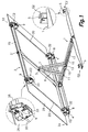
- FIGS. 1 to 4 show a solar tracker according to a first embodiment of the present invention, comprising a base 1 formed by connected metal sections forming an "H" shape and a solar panel 2 made up of a support structure 25 formed by connected metal sections forming an "H" shape supporting a photovoltaic panel 26.
- the photovoltaic panel 26 is secured to the support structure 25 by clamps 31 best shown in the enlarged details of Figures 6 and 7 .
- the solar panel 2 has first and second opposite ends 2a, 2b.
- the first end 2a can be connected to the base 1 by a first shaft E1 and the second end 2b can be connected to the base 1 by a second shaft E2, such that the solar panel 2 can pivot with respect to the base 1 around said first shaft E1 when the first end 2a is connected to the base 1 and the second end 2b is disconnected from the base 1 ( Figure 2 ) and the solar panel 2 can pivot with respect to the base 1 around said second shaft E2 when the second end 2b is connected to the base 1 and the first end 2a is disconnected from the base 1 ( Figure 4 ).
- the solar tracker includes a lifting mechanism installed in the base 1 and connected to the solar panel 2 in an intermediate region between said first and second ends 2a, 2b.
- This lifting mechanism is driven by a lifting/lowering actuator 10 for pivoting the solar panel 2 between a raised position ( Figures 2 and 4 ) and a position parallel to the base 1 ( Figure 3 ) according to the relative movements of the sun.
- an automatic connection/disconnection device connecting the second end 2b of the solar panel 2 to the base 1 while at the same time disconnecting the first end 2a of the solar panel 2 from the base 1, and vice versa, every time the solar panel 2 reaches said position parallel to the base 1 for inverting the inclination of the solar panel 2 with respect to the base 1 when the lifting mechanism is driven for again moving the solar panel 2 from the position parallel to the base 1 towards said raised position.
- the first shaft E1 is defined by a pair of first coaxial journals 4 fixed to two corners of a first end of the base 1 and a pair of corresponding first coaxial half-bearings 8 fixed to two corners of the first end 2a of the solar panel 2
- the second shaft E2 is defined by a pair of second coaxial journals 5 fixed to two corners of a second end of the base 1 and a pair of corresponding second coaxial half-bearings 9 fixed to two corners of the second end 2b of the solar panel 2.
- the first and second half-bearings 8, 9 are formed by the rounded ends of notches formed in corresponding first and second casings 32, 33 of the automatic connection/disconnection device fixed to the solar panel 2, and are configured and arranged for receiving the respective first and second journals 4, 5 inserted in a radial direction in said notches when the solar panel 2 reaches said position parallel to the base 1.
- first and second journals 4, 5 are fixed to the base 1 and the first and second half-bearings 8, 9 together with the automatic connection/disconnection device are fixed to the solar panel 2
- a reverse construction in which the first and second journals 4, 5 are fixed to the solar panel 2 and the first and second half-bearings 8, 9 together with the automatic connection/disconnection device are fixed to the base 1 is within the scope of the present invention.
- An embodiment with only a first journal, a first half-bearing, a second journal and a second half-bearing is also within the scope of the present invention.
- First and second embodiments of the connection/disconnection device in relation to Figures 6-7 and 8-12 , respectively, will be described below in detail.
- FIG 5 shows the aforementioned lifting mechanism used for varying the inclination or the solar panel 2 with respect to the base 1.
- the lifting mechanism comprises first and second movable arms 6, 7 having an upper end connected to a middle region of the support structure 25 of the solar panel 2 by a first articulation 3 (see also Figures 1 to 4 ).
- the first arm 6 has a lower end connected by a second articulation 11 to a first movable support 16a in which a first nut 12 is fixed and the second movable arm 7 has a lower end connected by a third articulation 13 to a second movable support 16b in which a second nut 14 is fixed.
- first and second nuts 12, 14 are coupled respectively to first and second threaded regions 15a, 15b of a screw 15 supported in the base 1 and rotatably driven by the aforementioned lifting/lowering actuator 10.
- Said first and second threaded portions 15a, 15b of the screw 15 have opposite thread directions, such that when the screw is turned in one direction the first and second nuts 12, 14 move closer to one another and the first articulation 3 is raised for moving the solar panel 2 towards the raised position, and when it is turned in the direction opposite the first and second nuts 12, 14 move away from one another and the first articulation 3 moves downwards for moving the solar panel 2 towards the position parallel to the base.
- the lifting/lowering actuator 10 which in the example shown is an electronically controlled electric motor, is installed on a movable support 16 provided with an opening through which the screw 15 is inserted and operatively connected for driving the screw by means of a gear transmission 34.
- the first articulation 3 is parallel to the first and second shafts E1, E2
- the screw 15 has a rotation axis arranged in a direction perpendicular to the first and second shafts E1, E2
- the movable supports 16, 16a, 16b supporting the screw 15, the first and second nuts 14 and the lifting/lowering actuator 10 are installed such that they can move freely with respect to the base 1 along a guide 17 ( Figures 1 to 4 ) oriented in a direction parallel to said rotation axis of the screw 15.
- FIGS 6 and 7 show a first embodiment of the automatic connection/disconnection device, comprising first and second closing elements 18, 19 associated with the first and second first half-bearings 8, 9, respectively.
- Each of the aforementioned first closing elements 18 is installed in one of the first casings 32 such that it can move relative to the corresponding first half-bearing 8 between a closed position (shown on the left in Figure 7 ), in which said first closing element 18 closes the passage through the corresponding notch for retaining the first journal 4 coupled to the first half-bearing 8, and an open position (shown on the left in Figure 6 ), in which the first closing element 18 allows the first journal 4 to slide along the notch for being coupled and decoupled to/from the first half-bearing 8.
- each of the second closing elements 19 is installed in one of the second casings 33 such that it can move relative to the corresponding second half-bearing 9 between a closed position (shown on the right in Figure 6 ), in which the second closing element 19 closes the passage through the corresponding notch for retaining the second journal 5 coupled to the second half-bearing 9, and an open position (shown on the right in Figure 7 ), in which the second closing element 19 allows the second journal 5 to slide along the notch for being coupled and decoupled to/from the second half-bearing 9.
- the first and second closing elements 18, 19 are kinematically linked to one another by a linking member 20 such that when the first closing element 18 is moved to said open position the second closing element 19 is moved to said closed position, and vice versa.
- the aforementioned linking member 20 extends between the first and second casings 32, 33 and is assembled such that it can slide axially with respect thereto.
- the first closing element 18 is connected in an articulated manner to a first end of a first rocker 35 the second end of which is connected in an articulated manner to the linking member 20, and a first elastic element 23 connected to the first rocker 35 is installed in a biestable arrangement whereby said first elastic element 23 pushes the first closing element 18 towards the closed position and towards the open position from an intermediate neutral position.
- the second closing element 19 is connected in an articulated manner to a first end of a second rocker 36 the second end of which is connected in an articulated manner to the linking member 20, and a second elastic element 24 connected to the second rocker 36 is installed in a biestable arrangement whereby said second elastic element 24 pushes the second closing element 19 towards the closed position and towards the open position from an intermediate neutral position.
- a single elastic element connected to any element of the kinematic chain and installed in a biestable arrangement would be sufficient.
- the automatic connection/disconnection device further comprises a first activation lever 21 positioned in the first casing 32 at the entrance of the notch defining the first half-bearing 8 such that it is movable between a stand-by position (shown on the left in Figure 6 ), in which the first activation lever 21 interferes with the passage along the corresponding notch, and an activation position (shown on the left in Figure 7 ), in which the first activation lever 21 is withdrawn from the notch.
- This first activation lever 21 is pushed from the stand-by position to the activation position by the first journal 4 when the solar panel 2, after a downward pivoting movement around the second shaft E2, reaches said position parallel to the base 1 and the first journal 4 is inserted in the corresponding notch for being coupled with the first half-bearing 8.
- a second activation lever 22 is positioned in the second casing 33 at the entrance of the notch defining the second half-bearing 9 such that it is movable between a stand-by position (shown on the right in Figure 7 ), in which the second activation lever 22 interferes with the passage along the corresponding notch, and an activation position (shown on the right in Figure 6 ), in which the second activation lever 22 is withdrawn from the notch.
- This second activation lever 22 is pushed from the stand-by position to the activation position by the second journal 5 when the solar panel 2, after a downward pivoting movement around the first shaft E1, reaches the position parallel to the base 1 and the second journal 5 is inserted in the corresponding notch for being coupled with the second half-bearing 9.
- the first activation lever 21 is kinematically linked by a first connecting rod 37 to a first pusher 27 arranged relative to one end of the linking member 20 such that when the first activation lever 21 is moved by the first journal 4 from its stand-by position to its activation position the first pusher 27 pushes the linking member 20 and the latter in turn by means of the first rocker 35 moves the first closing element 18 from the open position to beyond said intermediate neutral position, from which the first elastic element 23 ends up suddenly moving the first closing element 18 to the closed position, whereby the first closing element 18 traps the first journal 4 in coupling with the first half-bearing 8 for defining the first shaft E1.
- the second closing element 19 is moved to its open position, whereby the second closing element 19 releases the second journal 5 so that it can be decoupled from the second half-bearing 9.
- the second activation lever 22 is kinematically linked by a second connecting rod 38 to a second pusher 28 arranged relative to the other end of the linking member 20 such that when the second activation lever 22 is moved by the second journal 5 from its stand-by position to its activation position the second pusher 28 pushes the linking member 20 and the latter in turn by means of the second rocker 36 moves the second closing element 19 from the open position to beyond said intermediate neutral position, from which the second elastic element 24 ends up suddenly moving the second closing element 19 to the closed position, whereby the second closing element 19 traps the second journal 5 in coupling with the second half-bearing 9 for defining the second shaft E2.
- the first closing element 18 is moved to its open position, whereby the first closing element 18 releases the first journal 4 so that it can be decoupled from the first half-bearing 8.
- Figures 8 to 12 show a second alternative embodiment of the automatic connection/disconnection device.
- the solar tracker comprises a base 1 and solar panel 2 comprising, for example, a support structure supporting at least one photovoltaic panel.
- the first shaft E1 is defined by the coupling of a pair of first coaxial journals 4 fixed to the base 1 with a pair of corresponding first coaxial half-bearings 8 formed by notches of first casings 32 fixed to the solar panel 2
- a second shaft E2 is defined by the coupling of a pair of second coaxial journals 5 fixed to the base 1 with a pair of corresponding second half-coaxial bearings 9 formed in the ends of notches formed in second casings 33 fixed to the solar panel 2.
- each of the first casings 32 there is a first closing element 18 and a first activation lever 21 positioned relative to the notch defining the first half-bearing 8.
- the first closing element 18 and the first activation lever 21 are formed in a single part which is movable between a first position (shown on the left in Figure 12 ), in which the first closing element 18 is in the open position and the first activation lever 21 is in the stand-by position, and a second position (not shown), in which the first closing element 18 is in the closed position and the first activation lever 21 is in the activation position.
- the first activation lever 21 is pushed by the first journal 4 from the stand-by position to the activation position when the first journal 4 is inserted in the corresponding notch, whereby the first closing element 18 retains the first journal 4 coupled to the first half-bearing 8, and the first closing element 18 is pushed from the closed position to the open position by the first journal 4 when the latter comes out of the corresponding notch and is decoupled from the first half-bearing 8.
- each of the second casings 32 there is a second closing element 19 and a second activation lever 22 positioned relative to the notch defining the second half-bearing 9.
- the second closing element 19 and the second activation lever 22 are formed in a single part which is movable between a first position (not shown), in which the first closing element 18 is in the open position and the first activation lever 21 is in the stand-by position, and a second position (shown on the right in Figure 12 ), in which the first closing element 18 is in the closed position and the first activation lever 21 is in the activation position.
- the second activation lever 22 is pushed by the second journal 5 from the stand-by position to the activation position when the second journal 5 is inserted in the corresponding notch, whereby the second closing element 19 retains the second journal 5 coupled to the second half-bearing 9, and the second closing element 19 is pushed from the closed position to the open position by the second journal 5 when the latter comes out of the corresponding notch and is decoupled from the second half-bearing 9.
- the automatic connection/disconnection device of this second embodiment further comprises a locking device configured for alternately locking the first and second closing elements 18, 19 in their respective closed positions, and for alternately unlocking the first and second closing elements 18, 19 and thereby allowing their movements between their respective closed and open positions.
- first closing support 41 is fixed in a middle region of this first connecting rod 39, assembled such that it can pivot around a first closing shaft 42 supported in the solar panel 2.
- This first closing support 41 has a first locking notch 43 (best shown in Figure 10 ).
- a first pusher 27 is associated with the first closing support 41, assembled such that it can pivot independently around said first closing shaft 42.
- This first pusher 27 has an appendage 44 configured for acting as a stop for the first connecting rod 39.
- the first pusher 27 is positioned relative to an end of a single linking member 20 extending between first and second ends 2a, 2b of the solar panel 2 and assembled such that it can slide axially with respect thereto.
- the first pusher 27 can be turned in a first direction by the first activation levers 21 for pushing the linking member 20, and it is turned in a second opposite direction by an elastic element (not shown) for recovering its initial position.
- a first locking member 29, which is assembled such that it can pivot around a first locking shaft 45 supported in the solar panel 2, has an upper end connected in an articulated manner to a first end of the linking member 20 and a lower end provided with a first locking element 46.
- This first locking member 29 can pivot between a locked position ( Figures 8 and 9 ), in which the first locking element 46 is inserted in the first locking notch 43 of the first closing support 41 for locking the first closing elements 18 in their closed positions, and an unlocked position (shown on the left in Figure 12 ), in which it allows the first closing elements 18 to move between said closed and open positions.
- a first elastic element 23 connected to the first locking member 29 is installed in a biestable arrangement, such that this first elastic element 23 pushes the first locking member 29 towards the locked position and towards the unlocked position from an intermediate neutral position.
- a second square cross-section connecting rod 40 is connected to one another by a second square cross-section connecting rod 40.
- a second closing support (not shown) is fixed in a middle region of this second connecting rod 40 assembled such that it can pivot around a second closing shaft 47 supported in the solar panel 2.
- This second closing support has a second locking notch 48 (shown by means of dotted lines in Figure 12 ).
- a second pusher 28 is associated with the second closing support, assembled such that it can pivot independently around said second closing shaft 47.
- This second pusher 28 has an appendage 49 configured for acting as a stop for the second connecting rod 40.
- the second pusher 28 is positioned relative to another opposite end of the linking member 20.
- the second pusher 28 can be turned in a first direction by the second activation levers 22 for pushing the linking member 20, and it is turned in a second opposite direction by an elastic element (not shown) for recovering its initial position.
- a second locking member 30, which is assembled such that it can pivot around a second locking shaft 50 supported in the solar panel 2, has an upper end connected in an articulated manner to a second end of the linking member 20 and a lower end provided with a second locking element 51 (shown by means of dotted lines in Figure 12 ).
- This second locking member 30 can pivot between a locked position (shown on the right in Figure 12 ), in which the second locking element 51 is inserted in the second locking notch 48 of the second closing support for locking the second closing elements 19 in their closed positions, and an unlocked position (not shown), in which it allows the second closing elements 18 to move between said closed and open positions.
- a second elastic element 24 connected to the second locking member 30 is installed in a biestable arrangement, such that this second elastic element 24 pushes the second locking member 30 towards the locked position and towards the unlocked position from an intermediate neutral position.
- the linking member 20 kinematically links the first and second locking elements 29, 30 to one another such that when the first locking member 29 is moved to its locked position the second locking member 30 is moved to its unlocked position, and vice versa.
- this kinematic link an alternative embodiment in which there is a single elastic element installed in a biestable arrangement and connected to any of the first and second locking elements 29, 30 or even to the linking member 20 for pushing the first and second locking elements 29, 30 towards their locked and unlocked positions from an intermediate neutral position is considered within the scope of the present invention.
- a variant of this second embodiment where the first and second activation levers 21, 22 are not formed in the same part as their respective first and second closing elements 18, 19, but are separate parts kinematically linked to the respective first and second closing elements 18, 19 by one or more connecting elements is also within the scope of present invention.
- the first and second activation levers 21, 22 can be positioned alternatively such that they are pushed from their stand-by positions to their activation positions by any element attached to the base 1 different from the first and second journals 4, 5 (or any element attached to the solar panel 2 different from the first and second journals 4, 5 in the case of the aforementioned reverse construction) when the solar panel 2 pivoting around the first or second shaft E1, E2 reaches said position parallel to the base 1.
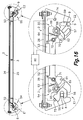
- FIGS 13 to 15 show a third embodiment of the solar tracker comprising, similarly to that described above in relation to the first and second embodiments, a base 1 and a solar panel 2 made up of a support structure 25 and photovoltaic panel 26.
- the solar panel 2 has first and second opposite ends 2a, 2b which can be connected to said base 1 by respective first and second mutually parallel shafts E1, E2, such that said solar panel 2 can pivot with respect to the base 1 around said first shaft E1 when the first end 2a is connected to the base 1 and the second end 2b is disconnected from the base 1, for example for adopting an eastern-oriented position ( Figure 13 ), and the solar panel 2 can pivot with respect to the base 1 around said second shaft E2 when the second end 2b is connected to the base 1 and the first end 2a is disconnected from the base 1, for example for adopting a western-oriented position ( Figure 15 ).
- the solar panel goes through a horizontal position, or more specifically through a position parallel to the base ( Figure 14 ), in which both first and second ends 2a, 2b of the solar panel are adjacent to the base 1.
- the solar tracker includes a lifting mechanism 6, 7, 11, 13, 15, 17 installed in the base 1 and connected to the solar panel 2 by an articulation 3 in an intermediate region between said first and second ends 2a, 2b.
- a lifting/lowering actuator 10 is operatively connected for moving said lifting mechanism and thereby pivoting said solar panel 2 around the first shaft E1 or the second shaft E2 between a position parallel to the base and a raised position according to the relative movements of the sun.
- the solar tracker further comprises an automatic connection/disconnection device connecting the first and second ends 2a, 2b of the solar panel 2 to the base 1, and vice versa, when the solar panel 2 reaches said position parallel to the base 1.
- the mentioned automatic connection/disconnection device comprises a first connection/disconnection mechanism 54 cooperating with a first connection/disconnection actuator 52 for connecting/disconnecting the first end 2a of the solar panel 2 to/from the base 1, a second connection/disconnection mechanism 55 cooperating with a second connection/disconnection actuator 53 for connecting/disconnecting the second end 2b of the solar panel 2 to/from the base 1, and electronic control means 60 configured for controlling the operation of said first and second connection/disconnection actuators 52, 53 in cooperation with detection means arranged for detecting at least the position of the solar panel 2 parallel to the base 1.
- the first and second connection/disconnection mechanisms 54, 55 are mechanically independent and the mentioned electronic control means 60 are configured for providing a tracking mode and a secure storage mode.
- the tracking mode the second connection/disconnection mechanism 55 connects the second end 2b of the solar panel 2 to the base 1 while at the same time the first connection/disconnection mechanism 54 disconnects the first end 2a from the solar panel 2 of the base 1, and vice versa, for inverting the inclination of the solar panel 2 with respect to the base 1 when the solar panel 2 reaches the position parallel to the base 1.
- the first and second connection/disconnection mechanisms 54, 55 connect the first and second ends 2a, 2b of the solar panel 2 to the base 1 at the same time when the solar panel 2 is in the position parallel to the base 1, which provides greater resistance against the effects of the wind, for example in the event of a storm, or when the solar tracker is installed in the roof of a moving vehicle.
- the first shaft E1 is defined by a pair of first coaxial journals 4 (only one of which is shown in the drawings) fixed to the base 1 and corresponding first half-bearings 8 (only one of which is shown in the drawings) fixed to the solar panel 2.
- said second shaft E2 is defined by a pair of second journals 5 (only one of which is shown in the drawings) fixed to the base 1 and corresponding second half-bearings 9 (only one of which is shown in the drawings) fixed to the solar panel 2.
- Said first and second half-bearings 8, 9 are configured and arranged for receiving the corresponding first and second journals 4 in a radial direction when the solar panel 2 reaches the position parallel to the base 1.
- the first connection/disconnection mechanism 54 comprises a first closing element 56 which can rotate around a first closing shaft 67 between a closed position (on the left in Figures 16 and 18 ), in which said first closing element 56 retains the first journal 4 coupled to the first half-bearing 8, and an open position (on the left in Figure 17 ), in which the first closing element 56 allows coupling and decoupling the first journal 4 to/from the first half-bearing 8.
- the second connection/disconnection mechanism 55 comprises a second closing element 57 which can rotate around a second closing shaft 68 between a closed position (on the right in Figures 17 and 18 ), in which the second closing element 57 retains the second journal 5 coupled to the second half-bearing 9, and an open position (on the right in Figure 16 ), in which the second closing element 57 allows coupling and decoupling the second journal to/from of the second half-bearing 9.
- the first connection/disconnection mechanism 54 further comprises a first activation lever 58 positioned such that it is pushed from a stand-by position to an activation position by the first journal 4 when the solar panel 2 pivoting around the second shaft E2 reaches said position parallel to the base 1.
- This first activation lever 58 integrally rotates with the first closing element 56 such that when the first activation lever 58 is moved to its activation position it rotates the first closing element 56 from its open position to its closed position.
- the second connection/disconnection mechanism 55 comprises a second activation lever 59 positioned such that it is pushed from a stand-by position to an activation position by the second journal 5 when the solar panel 2 pivoting around the second shaft E2 reaches said position parallel to the base 1.
- the mentioned second activation lever 59 integrally rotates with the second closing element 57, such that when the second activation lever 59 is moved to its activation position it rotates the second closing element 57 from its open position to its closed position.
- first closing element 56 is configured and arranged such that it is moved from its closed position to its open position by the first journal 4 when the solar panel 2 starts to pivot around the second shaft E2 from the position parallel to the base 1.
- second journal 5 moves the second closing element 57 from its closed position to its open position when the solar panel 2 starts to pivot around the first shaft E1 from the position parallel to the base 1.
- a first cam 65 integrally rotates with the first closing element 56 and the first activation lever 58 around the first closing shaft 67
- a second cam 66 integrally rotates with the second closing element 57 and the second activation lever 59 around the second closing shaft 68.
- These first and second cams 65, 66 have respective peripheral support surfaces and respective first and second interlocking elements 69, 70 in the form of notches in said peripheral support surfaces.
- the first connection/disconnection mechanism 54 further comprises a first locking member 61 which can rotate around a first locking shaft 71 parallel to said first closing shaft 67 between a locked position, in which said first locking member 61 is interlocked in the mentioned first interlocking element 69 and thereby locks the first closing element 56 in said closed position, and an unlocked position, in which the first locking member 61 is released from the first interlocking element 69 and allows the first closing element 56 to move freely between said closed and open positions.
- the second connection/disconnection mechanism 55 comprises a second locking member 62 which can rotate around a second locking shaft 72 parallel to said second closing shaft 68 between a locked position, in which said second locking member 62 is interlocked in said second interlocking element 70 and thereby locks the second closing element 57 in said closed position, and an unlocked position, in which the second locking member 62 is released from the second interlocking element 70 and allows the second closing element 57 to move between its closed and open positions.
- a first elastic element 63 such as a metal spring, pushes the first locking member 61 towards its locked position and the mentioned first connection/disconnection actuator 52, which in this third embodiment is, for example, an electromagnetic actuator, is arranged for pushing first locking member 61 towards its unlocked position against the force of said first elastic element 63.
- a second elastic element 64 pushes the second locking member 62 towards its locked position and said second connection/disconnection actuator 53, which can also comprise an electromagnetic actuator, is arranged for pushing the second locking member 62 towards its unlocked position against the force of said second elastic element 64.
- a tracking mode when the electronic control means 60 activate the operation of one of the first and second connection/disconnection actuators 52, 53 from a closed position (as shown on the left in Figures 16 and 18 or on the right in Figures 17 and 18 ), the latter act on the corresponding first or second locking member 61, 62 and unlock it from the first interlocking element 69.
- the electronic control means 60 then activate the operation of the lifting/lowering actuator 10 to start lifting the panel 2, whereby the corresponding journal 4, 5 moves the closing element 56, 57, which has just been released, towards its open position while the solar panel 2 starts to pivot around the opposite shaft E1, E2, which remains connected and with the corresponding connection/disconnection mechanism 54, 55 locked.
- the lifting movement of the solar panel 2 is started while the locking member 61, 62 is kept in its unlocked position by the corresponding connection/disconnection actuator 52, 53.
- the cam 65, 66. has rotated a certain angle, the operation of the corresponding connection/disconnection actuator 52, 53 can be deactivated since the locking member 61, 62 pushed by the elastic element 63, 64 is supported on the peripheral support surface and keeps the connection/disconnection mechanism 54, 55 released.
- the first connection/disconnection mechanism 54 comprises a first closing element 56 which can rotate around a first closing shaft 67 between a closed position (on the left in Figure 19 ), in which said first closing element 56 retains the first journal 4 coupled to the first half-bearing 8, and an open position (not shown), in which the first closing element 56 allows coupling and decoupling the first journal 4 to/from the first half-bearing 8.
- the second connection/disconnection mechanism 55 comprises a second closing element 57 which can rotate around a second a closing shaft 68 between a closed position (not shown), in which the second closing element 57 retains the second journal 5 coupled to the second half-bearing 9, and an open position (on the right in Figure 19 ), in which the second closing element 57 allows coupling and decoupling the second journal 5 to/from the second half-bearing 9.
- the first connection/disconnection mechanism 54 includes a first connection/disconnection actuator 52, which is operatively connected for moving said first closing element 56 between its open position and its closed position.
- the mentioned first connection/disconnection actuator 52 is an electric motor which rotates a first cogwheel 75 meshed with a first gear wheel sector 77 integrally rotating with the first closing element 56.
- the second connection/disconnection mechanism 55 includes a second connection/disconnection actuator 53, which comprises an electric motor that rotates a second cogwheel 76 meshed with a second gear wheel sector 78 integrally rotating with the second closing element 57, such that the second connection/disconnection actuator 53 is operatively connected for moving said second closing element 57 between its open position and its closed position.
- first and second connection/disconnection actuators 52, 53 can be selected from a group comprising electric motors, electromagnetic actuators, hydraulic actuators and pneumatic actuators.
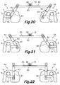
- Figures 20 to 22 show another variant of the third embodiment, where the first and second connection/disconnection mechanisms 54, 55 are moved by a single connection/disconnection actuator 79.
- each of the first and second closing elements 56, 57 is linearly movable between an open position (on the right in Figure 20 and on the left in Figure 21 ), a first closed position (on the left in Figure 20 and on the right in Figure 21 ), and a second closed position (on the left and right in Figure 22 ).
- the first and second connection/disconnection mechanisms 54, 55 comprise respective first and second rockers 81, 82 installed such that they can rotate around respective shafts 83, 84.
- Each of these first and second rockers 81, 82 have an end connected in an articulated manner to the corresponding first and second closing element 56, 57 and another end connected in an articulated manner to a linking member 80 kinematically linking the first and second connection/disconnection mechanisms 54, 55 to one another.
- Said linking member 80 has a rack gearing 85 and a single connection/disconnection actuator 79 rotating a cogwheel 86 meshed with said rack gearing 85.
- the mentioned single connection/disconnection actuator 79 kinematically moves the first and second connection/disconnection mechanisms 54, 55 together between a first position ( Figure 20 ), in which the first closing element 56 is in its first closed position and the second closing element 57 is in its open position, a second position ( Figure 21 ), in which the first closing element 56 is in its open position and the second closing element 57 is in its first closed position, and a third position ( Figure 22 ), in which both first and second closing elements 56, 57 are in their respective second closed positions.
- the electronic control means 60 in cooperation with detection means (not shown) control the operation of the single connection/disconnection actuator 79 for providing a tracking mode, in which the first and second connection/disconnection mechanisms 54, 55 alternate the first and second positions ( Figures 20 and 21 ), and a secure storage mode, in which the first and second connection/disconnection mechanisms 54, 55 are in the third position ( Figure 22 ).
- first and second closing elements 56, 57 allow one open position and two closed positions
- first and second connection/disconnection mechanisms 54, 55 are kinematically linked by a linking member 80
- a single connection/disconnection actuator 79 is operatively connected for moving the first and second connection/disconnection mechanisms 54, 55 between three positions equivalent to those described above.
- the single connection/disconnection actuator 79 can be selected from a group comprising an electric motor, an electromagnetic actuator, a hydraulic actuator and a pneumatic actuator.
- the electronic control means 60 can be programmable and can include a user interface whereby a user can establish a program, select the tracking mode or the secure storage mode, etc.
- the aforementioned detection means comprise first and second micro switches 73 arranged for detecting the first and second activation levers 58, 59 in their activation positions, respectively, which are equivalent to the closed positions of the first and second closing element 56, 57.
- the first and second micro switches 73, 74 could be arranged for detecting any one of the mobile components of the corresponding first and second connection/disconnection mechanisms 54, 55 when said mobile component was in a position indicating that the first or second end 2a, 2b of the solar panel 2 is connected to the base 1 with a similar result.
- at least one position detector, or even a single position detector, such as a micro switch, could be arranged for detecting the position of the solar panel 2 parallel to the base 1.
Landscapes
- Engineering & Computer Science (AREA)
- Physics & Mathematics (AREA)
- Life Sciences & Earth Sciences (AREA)
- Sustainable Development (AREA)
- Sustainable Energy (AREA)
- Thermal Sciences (AREA)
- Chemical & Material Sciences (AREA)
- Combustion & Propulsion (AREA)
- Mechanical Engineering (AREA)
- General Engineering & Computer Science (AREA)
- Photovoltaic Devices (AREA)
Description
- The present invention relates to a simple, compact and economical solar tracker suitable for small-sized solar panels with, for example, a single photovoltaic panel. The solar tracker of the present invention includes two alternating parallel rotation shafts behaving like a single rotation shaft for daily tracking in the east-west direction and is provided for being installed with a fixed inclination in the north-south direction considered the most suitable according to the latitude of the geographic site where it is located, although it could also optionally be used for tracking in the north-south direction daily or seasonally. Due to its small size and low weight, the solar tracker of the present invention can also be applied as a portable solar power unit.
- For better efficiency of solar panels, for example photovoltaic panels, the sun rays should strike them in the most perpendicular direction possible. To that end, solar trackers are usually provided with a first tracking mechanism for orienting the solar panels in the east-west direction and a second tracking mechanism for orienting the solar panels in the north-south direction for the purpose of tracking the relative movements of the sun during the day, including the yearly cycle variations occurring during the seasons. East-west direction tracking is the most important because it involves a movement covering a very broad arc, whereas north-south direction tracking involves a movement covering a considerably smaller arc.
- The implementation of the two aforementioned tracking mechanisms in a two-shaft solar tracker entails a complex construction and increase manufacturing cost.
- Accordingly, the present invention proposes a light-weight and economical solar tracker provided with a single tracking mechanism for orienting at least one solar panel in the east-west direction, taking into account that the solar panel and the tracking mechanism are supported in a base which can be installed in a stationary manner at a mid-point inclination in the north-south direction according to the latitude of the site where it is installed. The slight loss of efficiency due to tracking in a single shaft is offset with the low cost, light weight, ease of transport and ease of installation of the solar tracker of the present invention.
- Document
US 2011/0061644 A1 discloses a low-profile solar energy collection system comprising a base for assembling the system on a suitable substrate and a plurality of solar panels arranged next to one another on the base. A first set of solar panels are movable relative to a second set of solar panels for tracking the relative movements of the sun during the day. The solar panels of the first set are arranged in an alternating manner with the solar panels of the second set. In one embodiment, the solar panels of the second set are arranged in a stationary manner and in another embodiment they are movable relative to the solar panels of the first set. A drawback of this system is that in at all times only one set of solar panels, i.e., only half of the solar panels, receive the rays of the sun in suitable conditions. - Document
CN 1010981133 A - If for simplicity's sake a person skilled in the art decided to use only the main tracking mechanism in the east-west direction in the solar tracker of the mentioned document
CN 101098113 A , it would correspond to the rotational movement of the horizontal support around the vertical shaft, which entails greater constructive complexity in comparison with the pivoting movement mechanism. If the person skilled in the art decided to use the pivoting movement mechanism of the solar panel around the horizontal shaft for tracking in the east-west direction, the angle covered by this mechanism would be insufficient. - Document
DE 10129633 C1 describes a device for solar tracking of solar modules running on bearings on a main housing on rails. A connecting rod fits parallel to the main housing on rails and has a catch with two guide devices, one behind the other in an axial direction. One end of each of two stay bars swivels in each guide device and runs on sliding bearings lengthwise across the guide devices. Another end of each of the two stay bars swivels on a link with a fastening point for a solar module. - Document
WO 8200719 A1 - The present invention contributes to solving the foregoing and other drawbacks by providing a solar tracker comprising a base on which a solar panel is installed having first and second opposite ends. The aforementioned first and second ends of the solar panel can be connected to said base by respective first and second mutually parallel shafts by means of an automatic connection/disconnection device connecting the second end of the solar panel to the base while at the same time disconnecting the first end of the solar panel from the base, and vice versa, every time the solar panel reaches a position parallel to the base, such that the solar panel can pivot with respect to the base around said first shaft when the first end is connected to the base and the second end is disconnected from the base, and the solar panel can pivot with respect to the base around said second shaft when the second end is connected to the base and the first end is disconnected from the base.
- The solar tracker further comprises a lifting mechanism connected to the solar panel in an intermediate region between said first and second ends and a lifting/lowering actuator operatively connected for moving said lifting mechanism and thereby pivoting said solar panel alternately around the first shaft and around the second shaft passing through said position parallel to the base according to the relative movements of the sun. Therefore, the lifting/lowering actuator and the lifting mechanism are configured for pivoting the solar panel between a raised position and a position parallel to the base and the automatic connection/disconnection device is configured for inverting the inclination of the solar panel with respect to the base every time the solar panel reaches the position parallel to the base and the lifting mechanism is driven again for moving the solar panel from the position parallel to the base towards the raised position.
- In one embodiment, the first shaft is defined by at least a first journal fixed to the base and at least a corresponding first half-bearing fixed to the solar panel, or vice versa, and the second shaft is defined by at least a second journal fixed to the base and at least a corresponding second half-bearing fixed to the solar panel, or vice versa. The first and second half-bearings are formed, for example; by closed and rounded ends of notches, and are configured arid arranged for receiving the corresponding first and second journals in a radial direction when the solar panel reaches the position parallel to the base.
- The aforementioned automatic connection/disconnection device comprises at least a first closing element associated with the first half-bearing and a second closing element associated with the second half-bearing. Said first closing element is movable between a closed position, in which the first closing element retains the first journal coupled to the first half-bearing, and an open position, in which the first closing element allows the first journal to move along the corresponding notch and to be coupled and decoupled to/from the first half-bearing. Similarly, said second closing element is movable between a closed position, in which the second closing element retains the second journal coupled to the second half-bearing, and an open position, in which the second closing element allows the second journal to move along the corresponding notch and to be coupled and decoupled to/from the second half-bearing.
- In one embodiment, the automatic connection/disconnection device includes at least one linking member kinematically linking said first and second closing elements to one another such that when the first closing element is moved to said open position the second closing element is moved to said closed position, and vice versa. At least one elastic element is installed in a biestable arrangement whereby said elastic element pushes one of the first and second closing elements towards the closed position and towards the open position from an intermediate neutral position, and the other closing element follows the opposite movements in accordance with the link kinematically provided by the linking member, although alternatively the automatic connection/disconnection device can include a first elastic element installed in a biestable arrangement associated with the first closing element and a second elastic element installed in a biestable arrangement associated with the second closing element.
- In this embodiment, the automatic connection/disconnection device further comprises a first activation lever positioned such that it is pushed from a stand-by position to an activation position by an element attached to the base or to the solar panel when the solar panel pivoting around the second shaft reaches said position parallel to the base. This first activation lever is kinematically linked to a first pusher arranged for moving said first closing element from the open position to beyond said intermediate neutral position when the first activation lever is pushed to said activation position, such that the closing element suddenly moves from the intermediate neutral position to the closed position pushed by the elastic element.
- Similarly, a second activation lever is positioned such that it is pushed from a stand-by position to an activation position by an element attached to the base or to the solar panel when the solar panel pivoting around the first shaft reaches said position parallel to the base, said second activation lever being kinematically linked to a second pusher arranged for moving said second closing element from the open position to beyond said intermediate neutral position when the second activation lever is pushed to said activation position.
- Preferably, the first and second activation levers are associated with the first and second half-bearings such that they interfere in the passage along the corresponding notches when they are located in the stand-by position and are pushed by the respective first and second journals when they are received in the corresponding first and second half-bearings.
- According to another alternative embodiment, the automatic connection/disconnection device comprises a first locking member movable between a locked position, in which the first locking member locks the first closing element in said closed position, and an unlocked position, in which the first locking member allows the first closing element to move between said closed and open positions, and a second locking member movable between a locked position, in which the second locking member locks the second closing element in said closed position, and an unlocked position, in which the second locking member allows the second closing element to move between said closed and open positions. In this embodiment, the linking member kinematically links said first and second locking elements to one another such that when the first locking element is moved to said locked position the second locking element is moved to said unlocked position, and vice versa.
- In this embodiment, the automatic connection/disconnection device further comprises at least one elastic element installed in a biestable arrangement whereby said elastic element pushes one of the first and second locking elements towards the locked position and towards the unlocked position from an intermediate neutral position. A single elastic element is sufficient in accordance with the kinematic link provided by the linking member, although alternatively the automatic connection/disconnection device can include a first elastic element installed in a biestable arrangement and associated with the first locking element and a second elastic element installed in a biestable arrangement and associated with the second locking element for pushing them towards the locked position and towards the unlocked position from an intermediate neutral position.
- In this embodiment, the automatic connection/disconnection device further comprises a first activation lever positioned such that it is pushed from a stand-by position to an activation position by an element attached to the base or to the solar panel when the solar panel pivoting around the second shaft reaches said position parallel to the base. This first activation lever is kinematically linked to a first pusher arranged for moving said first locking element from the unlocked position to beyond said intermediate neutral position when the first activation lever is pushed to said activation position. Therefore, the first locking element is suddenly moved to the locked position by the elastic element.
- Similarly, a second activation lever is positioned such that it is pushed from a stand-by position to an activation position by an element attached to the base or to the solar panel when the solar panel pivoting around the first shaft reaches said position parallel to the base, said second activation lever being kinematically linked to a second pusher arranged for moving said second locking element from the unlocked position to beyond said intermediate neutral position when the second activation lever is pushed to said activation position.
- When the first closing element is unlocked, the first journal interferes with the closing element and returns it to the open position during an initial phase of the pivoting movement of the solar panel around the second shaft from the position parallel to the base, and when the second closing element is unlocked, the second journal interferes with the closing element and returns it to the open position during an initial phase of the pivoting movement of the solar panel around the first shaft from the position parallel to the base.
- Preferably, in this embodiment the first and second activation levers are positioned at the entrance of the corresponding first and second half-bearings such that they are pushed from the stand-by position to the activation position by the respective first and second journals when they are received in the corresponding half-bearings. Also preferably, the first activation lever and the first closing element are formed in a single part and the second activation lever and the second closing element are formed in a single part.
- In another alternative embodiment, said automatic connection/disconnection device comprises a first connection/disconnection mechanism connecting/disconnecting the first end of the solar panel to/from the base, a second connection/disconnection mechanism connecting/disconnecting the second end of the solar panel to/from the base, at least one connection/disconnection actuator cooperating with said first and second connection/disconnection mechanisms, and electronic control means configured for controlling the operation of said at least one connection/disconnection actuator in cooperation with detection means arranged for detecting at least the position of the solar panel parallel to the base to operate the solar tracker according to a tracking mode in which the second connection/disconnection mechanism connects the second end of the solar panel to the base while at the same time said first connection/disconnection mechanism disconnects the first end of the solar panel from the base, and vice versa, when the solar panel reaches the position parallel to the base.
- The mentioned electronic control means can be configured to operate the solar tracker further according to a secure storage mode in which the first and second connection/disconnection mechanisms connect the first and second ends of the solar panel to the base at the same time when the solar panel is in the position parallel to the base.
- Thus, when the solar tracker is installed with its base in a fixed stationary position, for example on a fixed structure such as a building rooftop or on the roof of a parked vehicle, the present improvements allow providing the following solar tracker operation:
- a) At night the solar tracker remains in a rest position with the solar panel parallel to the base. Preferably, in this position the two ends of the solar panel are connected to the base with both rotation shafts retained in their anchoring points according to the secure storage mode.
- b) At dawn, the connection/disconnection mechanism corresponding to the west side is activated to release the connection of the end of the solar panel located in the west side with the base and the lifting mechanism is driven to raise the solar panel which rotates around the shaft located in the east side for orienting the solar panel towards the east in a maximum lift position according to the tracking mode.
- c) Throughout the entire morning, the tracker gradually moves from said maximum lift position oriented towards the east to the position parallel to the base which is reached by mid-day.
- d) From the position parallel to the base corresponding to mid-day, and following the relative movement of the sun, the connection/disconnection mechanism corresponding to the east side is activated to release the connection of the end of the solar panel located in the east side with the base and at the same time the connection/disconnection mechanism corresponding to the west side is activated to establish the connection of the end of the solar panel located in the west side with the base again. The lifting mechanism is then driven for raising the solar panel which now rotates around the shaft located in the west side for orienting the solar panel towards the west until reaching a maximum lift position at the end of the evening according to the tracking mode.
- e) After sunset, the mechanisms of the solar tracker are driven to return the solar panel to the position parallel to the base and to again connect the two ends of the solar panel to the base for the night, according to the secure storage mode.
- Preferably, the connection/disconnection mechanisms are configured such that the first or second connection/disconnection actuator for opening the connection between the corresponding end of the solar panel and the base is activated only for the time necessary to allow the release of the corresponding shaft.
- When strong wind, for example in the case of a storm, is forecasted, or when the solar tracker is installed on a moving structure, for example on the roof of a moving vehicle, the mechanisms of the solar tracker are driven to arrange the solar panel at the position parallel to the base and to connect the two ends of the solar panel to the base according to the secure storage mode.
- This embodiment with one or more connection/disconnection actuators provides the following advantages:
- Better movement flexibility since it allows, for example, rotating the solar panel again around the same shaft used for reaching the position parallel to the base when the solar panel is in the position parallel to the base; and
- Possibility of anchoring both ends of the solar panel to the base at the same time. This is useful to increase the resistance against the effects produced by wind when the solar panel is in the position parallel to the base, for example in the event of a storm or when the solar tracker is fixed on the roof of a moving vehicle.
- The electronic control means can be programmable and can include a user interface whereby a user can establish a program, select an operating mode, etc.
- Preferably, each of the first and second shafts is defined by at least one journal fixed to the base and at least one corresponding half-bearing fixed to the solar panel, or vice versa, wherein the half-bearing is configured and arranged for receiving the corresponding journal in a radial direction when the solar panel reaches the position parallel to the base. Also preferably, each of the first and second connection/disconnection mechanisms comprises at least one closing element movable between a closed position, in which said the closing element retains the journal coupled to the half-bearing, and an open position, in which the closing element allows coupling and decoupling the journal to/from the half bearing.
- In one embodiment, each of the first and second connection/disconnection mechanisms comprises a locking member movable between a locked position, in which said locking member locks the closing element in said closed position, and an unlocked position, in which the locking member allows the closing element to move between said closed and open positions. For example, an elastic element pushes the locking member towards its locked position and a corresponding connection/disconnection actuator is arranged for pushing the locking member towards its unlocked position against the force of said elastic element. Furthermore, each of the closing elements is arranged for moving a cam which keeps the corresponding locking member in its unlocked position while the closing element is in its open position.
- Each of the first and second connection/disconnection mechanisms further comprises an activation lever positioned such that it is pushed from a stand-by position to an activation position by an element attached to the base or to the solar panel when the solar panel pivoting around the opposite shaft reaches said position parallel to the base, and said activation lever is arranged for moving the corresponding closing element from its open position to its closed position when the activation lever is moved to its activation position. Likewise, an element attached to the base or to the solar panel moves the closing element from its closed position to its open position when the solar panel starts to pivot around the shaft corresponding to the opposite end from the position parallel to the base and while the locking member is kept in its unlocked position by the corresponding connection/disconnection actuator.
- Although it is not essential, each closing element, its corresponding activation lever and its corresponding cam integrally rotate around a closing shaft, and the corresponding locking member rotates around a locking shaft parallel to said closing shaft. Each cam comprises a first interlocking element in which the locking member is interlocked in its locked position.
- In another embodiment, the first connection/disconnection mechanism has a first connection/disconnection actuator operatively connected for moving the first closing element between its open position and its closed position, and the second connection/disconnection mechanism has a second connection/disconnection actuator operatively connected for moving the second closing element between its open position and its closed position.
- In yet another embodiment, each of the first and second closing elements is movable between an open position, a first closed positions, and second closed position. Furthermore, the first and second connection/disconnection mechanisms are kinematically linked to one another by a linking member such that they are moved together by a single connection/disconnection actuator between a first position, in which the first closing element is in its first closed position and the second closing element is in its open position, a second position, in which the first closing element is in its open position and the second closing element is in its first closed position, and a third position, in which both first and second closing elements are in their respective second closed positions.
- In any of the embodiments, the first connection/disconnection actuator, the second connection/disconnection actuator or the only connection/disconnection actuator can be, for example, an electric motor, an electromagnetic actuator, a hydraulic actuator or a pneumatic actuator.
- In a preferred embodiment, the solar panel comprises a support structure supporting at least one photovoltaic panel, and the aforementioned first and second half-bearings together with the automatic connection/disconnection device are fixed to said support structure of the solar panel, whereas said first and second journals are fixed to the base.
- The lifting mechanism comprises at least first and second movable arms having upper ends connected to the solar panel by a first articulation. The first movable arm has a lower end connected by a second articulation to a nut coupled to a first threaded region of a screw supported in the base and the second movable arm has a lower end connected by a third articulation to a second nut coupled to a second threaded region of the screw. Said first and second threaded portions of the screw have opposite thread directions, and the screw is rotatably driven by the aforementioned lifting/lowering actuator, which can be, for example, an electronically controlled electric motor.
- The rotation axis of the screw is arranged in a direction perpendicular to the first and second shafts, and the screw, said first and second nuts and the lifting/lowering actuator are installed such that the assembly moves freely with respect to the base along a guide oriented in a direction parallel to said rotation axis of the screw.
- The foregoing and other features and advantages will be better understood from the following detailed description of several embodiments with reference to the attached drawings, in which:
-
Figure 1 is a perspective view of a solar tracker according to a first embodiment of the present invention, with two enlarged details; -
Figure 2 is a side elevational view of the solar tracker in an eastern-oriented position corresponding to the morning; -
Figure 3 is a side elevational view of the solar tracker in a horizontal position corresponding to mid-day; -
Figure 4 is a side elevational view of the solar tracker in a western-oriented position corresponding to the evening; -
Figure 5 is a perspective view of a lifting mechanism of the solar tracker ofFigure 1 ; -
Figure 6 is a side elevational view with two enlarged details of an automatic connection/disconnection device of the solar tracker ofFigure 1 when the solar tracker is located in the eastern-oriented position shown inFigure 2 ; -
Figure 7 is a side elevational view with two enlarged details of the automatic connection/disconnection device ofFigure 6 when the solar tracker is located in the western-oriented position shown inFigure 4 ; -
Figure 8 is a schematic partial perspective view of an automatic connection/disconnection device of a solar tracker according to a second embodiment of the present invention; -
Figure 9 is a partial perspective view illustrating a locking member of the automatic connection/disconnection device ofFigure 8 ; -
Figures 10 and 11 are partial perspective views illustrating a pusher of the automatic conneetion/disconnection device ofFigure 8 ; -
Figure 12 is a side elevational view with two enlarged details of the automatic connection/disconnection device ofFigure 8 when the solar tracker is located in the western-oriented position shown inFigure 4 ; -
Figures 13 to 15 are side views of a solar tracker according to a third embodiment of the present improvements in an eastern-oriented position corresponding to the morning, a horizontal position corresponding to mid-day, and a western-oriented position corresponding to the evening, respectively, in a tracking mode; -
Figure 16 is a side elevational view of a solar panel of the solar tracker ofFigures 13 to 15 with two enlarged details showing the arrangement of connection/disconnection mechanisms when the solar tracker is in the eastern-oriented position; -
Figure 17 is a side elevational view of the solar panel of the solar tracker ofFigures 13 to 15 with two enlarged details showing the arrangement of the connection/disconnection mechanisms when the solar tracker is in the western-oriented position; -
Figure 18 is a side elevational view of the solar panel of the solar tracker ofFigures 13 to 15 with two enlarged details showing the arrangement of the connection/disconnection mechanisms when the solar tracker is in the horizontal position in a secure storage mode; -
Figure 19 is a side elevational view of a solar panel of a solar tracker according to a variant of the third embodiment of the present invention with two enlarged details showing the arrangement of connection/disconnection mechanisms when the solar tracker is in the eastern-oriented position in a tracking mode; and -
Figures 20 to 22 are schematic side views of an automatic connection/disconnection device of a solar tracker according to another variant of the third embodiment of the present improvements in first, second and third positions. - First in reference to
Figures 1 to 4 , such figures show a solar tracker according to a first embodiment of the present invention, comprising abase 1 formed by connected metal sections forming an "H" shape and asolar panel 2 made up of asupport structure 25 formed by connected metal sections forming an "H" shape supporting aphotovoltaic panel 26. Thephotovoltaic panel 26 is secured to thesupport structure 25 byclamps 31 best shown in the enlarged details ofFigures 6 and7 . Thesolar panel 2 has first and second opposite ends 2a, 2b. Thefirst end 2a can be connected to thebase 1 by a first shaft E1 and thesecond end 2b can be connected to thebase 1 by a second shaft E2, such that thesolar panel 2 can pivot with respect to thebase 1 around said first shaft E1 when thefirst end 2a is connected to thebase 1 and thesecond end 2b is disconnected from the base 1 (Figure 2 ) and thesolar panel 2 can pivot with respect to thebase 1 around said second shaft E2 when thesecond end 2b is connected to thebase 1 and thefirst end 2a is disconnected from the base 1 (Figure 4 ). - The solar tracker includes a lifting mechanism installed in the
base 1 and connected to thesolar panel 2 in an intermediate region between said first andsecond ends actuator 10 for pivoting thesolar panel 2 between a raised position (Figures 2 and 4 ) and a position parallel to the base 1 (Figure 3 ) according to the relative movements of the sun. - There is installed in the
solar panel 2 an automatic connection/disconnection device connecting thesecond end 2b of thesolar panel 2 to thebase 1 while at the same time disconnecting thefirst end 2a of thesolar panel 2 from thebase 1, and vice versa, every time thesolar panel 2 reaches said position parallel to thebase 1 for inverting the inclination of thesolar panel 2 with respect to thebase 1 when the lifting mechanism is driven for again moving thesolar panel 2 from the position parallel to thebase 1 towards said raised position. - The first shaft E1 is defined by a pair of first
coaxial journals 4 fixed to two corners of a first end of thebase 1 and a pair of corresponding first coaxial half-bearings 8 fixed to two corners of thefirst end 2a of thesolar panel 2, and the second shaft E2 is defined by a pair of secondcoaxial journals 5 fixed to two corners of a second end of thebase 1 and a pair of corresponding second coaxial half-bearings 9 fixed to two corners of thesecond end 2b of thesolar panel 2. The first and second half-bearings second casings solar panel 2, and are configured and arranged for receiving the respective first andsecond journals solar panel 2 reaches said position parallel to thebase 1. - A person skilled in the art will understand that although in the embodiments shown and described the first and
second journals base 1 and the first and second half-bearings solar panel 2, a reverse construction (not shown) in which the first andsecond journals solar panel 2 and the first and second half-bearings base 1 is within the scope of the present invention. An embodiment with only a first journal, a first half-bearing, a second journal and a second half-bearing is also within the scope of the present invention. First and second embodiments of the connection/disconnection device in relation toFigures 6-7 and8-12 , respectively, will be described below in detail. -
Figure 5 shows the aforementioned lifting mechanism used for varying the inclination or thesolar panel 2 with respect to thebase 1. The lifting mechanism comprises first and secondmovable arms support structure 25 of thesolar panel 2 by a first articulation 3 (see alsoFigures 1 to 4 ). Thefirst arm 6 has a lower end connected by asecond articulation 11 to a firstmovable support 16a in which afirst nut 12 is fixed and the secondmovable arm 7 has a lower end connected by athird articulation 13 to a secondmovable support 16b in which a second nut 14 is fixed. - These first and
second nuts 12, 14 are coupled respectively to first and second threadedregions screw 15 supported in thebase 1 and rotatably driven by the aforementioned lifting/loweringactuator 10. Said first and second threadedportions screw 15 have opposite thread directions, such that when the screw is turned in one direction the first andsecond nuts 12, 14 move closer to one another and thefirst articulation 3 is raised for moving thesolar panel 2 towards the raised position, and when it is turned in the direction opposite the first andsecond nuts 12, 14 move away from one another and thefirst articulation 3 moves downwards for moving thesolar panel 2 towards the position parallel to the base. - The lifting/lowering
actuator 10, which in the example shown is an electronically controlled electric motor, is installed on amovable support 16 provided with an opening through which thescrew 15 is inserted and operatively connected for driving the screw by means of agear transmission 34. In the embodiment shown, thefirst articulation 3 is parallel to the first and second shafts E1, E2, thescrew 15 has a rotation axis arranged in a direction perpendicular to the first and second shafts E1, E2, and themovable supports screw 15, the first and second nuts 14 and the lifting/loweringactuator 10 are installed such that they can move freely with respect to thebase 1 along a guide 17 (Figures 1 to 4 ) oriented in a direction parallel to said rotation axis of thescrew 15. - It is also within the scope of the present invention another alternative embodiment (not shown) with an inverse construction, wherein the
screw 15 is supported on thesolar panel 2 and the first and secondmovable arms base 1 by a first articulation and respective upper ends articulately connected to a nut or to first and second nuts respectively coupled to first and second threadedportions screw 15, said first and second threadedportions -
Figures 6 and7 show a first embodiment of the automatic connection/disconnection device, comprising first andsecond closing elements bearings first closing elements 18 is installed in one of thefirst casings 32 such that it can move relative to the corresponding first half-bearing 8 between a closed position (shown on the left inFigure 7 ), in which saidfirst closing element 18 closes the passage through the corresponding notch for retaining thefirst journal 4 coupled to the first half-bearing 8, and an open position (shown on the left inFigure 6 ), in which thefirst closing element 18 allows thefirst journal 4 to slide along the notch for being coupled and decoupled to/from the first half-bearing 8. - Similarly, each of the
second closing elements 19 is installed in one of thesecond casings 33 such that it can move relative to the corresponding second half-bearing 9 between a closed position (shown on the right inFigure 6 ), in which thesecond closing element 19 closes the passage through the corresponding notch for retaining thesecond journal 5 coupled to the second half-bearing 9, and an open position (shown on the right inFigure 7 ), in which thesecond closing element 19 allows thesecond journal 5 to slide along the notch for being coupled and decoupled to/from the second half-bearing 9. - The first and
second closing elements member 20 such that when thefirst closing element 18 is moved to said open position thesecond closing element 19 is moved to said closed position, and vice versa. For that purpose, theaforementioned linking member 20 extends between the first andsecond casings first closing element 18 is connected in an articulated manner to a first end of afirst rocker 35 the second end of which is connected in an articulated manner to the linkingmember 20, and a firstelastic element 23 connected to thefirst rocker 35 is installed in a biestable arrangement whereby said firstelastic element 23 pushes thefirst closing element 18 towards the closed position and towards the open position from an intermediate neutral position. - Similarly, the
second closing element 19 is connected in an articulated manner to a first end of asecond rocker 36 the second end of which is connected in an articulated manner to the linkingmember 20, and a secondelastic element 24 connected to thesecond rocker 36 is installed in a biestable arrangement whereby said secondelastic element 24 pushes thesecond closing element 19 towards the closed position and towards the open position from an intermediate neutral position. It will be understood that in accordance with the kinematic link between the first andsecond closing elements member 20 and the first andsecond rockers - The automatic connection/disconnection device further comprises a
first activation lever 21 positioned in thefirst casing 32 at the entrance of the notch defining the first half-bearing 8 such that it is movable between a stand-by position (shown on the left inFigure 6 ), in which thefirst activation lever 21 interferes with the passage along the corresponding notch, and an activation position (shown on the left inFigure 7 ), in which thefirst activation lever 21 is withdrawn from the notch. Thisfirst activation lever 21 is pushed from the stand-by position to the activation position by thefirst journal 4 when thesolar panel 2, after a downward pivoting movement around the second shaft E2, reaches said position parallel to thebase 1 and thefirst journal 4 is inserted in the corresponding notch for being coupled with the first half-bearing 8. - Similarly, a
second activation lever 22 is positioned in thesecond casing 33 at the entrance of the notch defining the second half-bearing 9 such that it is movable between a stand-by position (shown on the right inFigure 7 ), in which thesecond activation lever 22 interferes with the passage along the corresponding notch, and an activation position (shown on the right inFigure 6 ), in which thesecond activation lever 22 is withdrawn from the notch. Thissecond activation lever 22 is pushed from the stand-by position to the activation position by thesecond journal 5 when thesolar panel 2, after a downward pivoting movement around the first shaft E1, reaches the position parallel to thebase 1 and thesecond journal 5 is inserted in the corresponding notch for being coupled with the second half-bearing 9. - The
first activation lever 21 is kinematically linked by a first connectingrod 37 to afirst pusher 27 arranged relative to one end of the linkingmember 20 such that when thefirst activation lever 21 is moved by thefirst journal 4 from its stand-by position to its activation position thefirst pusher 27 pushes the linkingmember 20 and the latter in turn by means of thefirst rocker 35 moves thefirst closing element 18 from the open position to beyond said intermediate neutral position, from which the firstelastic element 23 ends up suddenly moving thefirst closing element 18 to the closed position, whereby thefirst closing element 18 traps thefirst journal 4 in coupling with the first half-bearing 8 for defining the first shaft E1. At the same time, and in accordance with the kinematic link provided by the linkingmember 20 and the first andsecond rockers second closing element 19 is moved to its open position, whereby thesecond closing element 19 releases thesecond journal 5 so that it can be decoupled from the second half-bearing 9. - Similarly, the
second activation lever 22 is kinematically linked by a second connectingrod 38 to asecond pusher 28 arranged relative to the other end of the linkingmember 20 such that when thesecond activation lever 22 is moved by thesecond journal 5 from its stand-by position to its activation position thesecond pusher 28 pushes the linkingmember 20 and the latter in turn by means of thesecond rocker 36 moves thesecond closing element 19 from the open position to beyond said intermediate neutral position, from which the secondelastic element 24 ends up suddenly moving thesecond closing element 19 to the closed position, whereby thesecond closing element 19 traps thesecond journal 5 in coupling with the second half-bearing 9 for defining the second shaft E2. At the same time, and in accordance with the kinematic link provided by the linkingmember 20 and the first andsecond rockers first closing element 18 is moved to its open position, whereby thefirst closing element 18 releases thefirst journal 4 so that it can be decoupled from the first half-bearing 8. -
Figures 8 to 12 show a second alternative embodiment of the automatic connection/disconnection device. Similarly to the first embodiment, the solar tracker comprises abase 1 andsolar panel 2 comprising, for example, a support structure supporting at least one photovoltaic panel. The first shaft E1 is defined by the coupling of a pair of firstcoaxial journals 4 fixed to thebase 1 with a pair of corresponding first coaxial half-bearings 8 formed by notches offirst casings 32 fixed to thesolar panel 2, and a second shaft E2 is defined by the coupling of a pair of secondcoaxial journals 5 fixed to thebase 1 with a pair of corresponding second half-coaxial bearings 9 formed in the ends of notches formed insecond casings 33 fixed to thesolar panel 2. - In each of the
first casings 32 there is afirst closing element 18 and afirst activation lever 21 positioned relative to the notch defining the first half-bearing 8. Thefirst closing element 18 and thefirst activation lever 21 are formed in a single part which is movable between a first position (shown on the left inFigure 12 ), in which thefirst closing element 18 is in the open position and thefirst activation lever 21 is in the stand-by position, and a second position (not shown), in which thefirst closing element 18 is in the closed position and thefirst activation lever 21 is in the activation position. Thefirst activation lever 21 is pushed by thefirst journal 4 from the stand-by position to the activation position when thefirst journal 4 is inserted in the corresponding notch, whereby thefirst closing element 18 retains thefirst journal 4 coupled to the first half-bearing 8, and thefirst closing element 18 is pushed from the closed position to the open position by thefirst journal 4 when the latter comes out of the corresponding notch and is decoupled from the first half-bearing 8. - Similarly, in each of the
second casings 32 there is asecond closing element 19 and asecond activation lever 22 positioned relative to the notch defining the second half-bearing 9. Thesecond closing element 19 and thesecond activation lever 22 are formed in a single part which is movable between a first position (not shown), in which thefirst closing element 18 is in the open position and thefirst activation lever 21 is in the stand-by position, and a second position (shown on the right inFigure 12 ), in which thefirst closing element 18 is in the closed position and thefirst activation lever 21 is in the activation position. Thesecond activation lever 22 is pushed by thesecond journal 5 from the stand-by position to the activation position when thesecond journal 5 is inserted in the corresponding notch, whereby thesecond closing element 19 retains thesecond journal 5 coupled to the second half-bearing 9, and thesecond closing element 19 is pushed from the closed position to the open position by thesecond journal 5 when the latter comes out of the corresponding notch and is decoupled from the second half-bearing 9. - The automatic connection/disconnection device of this second embodiment further comprises a locking device configured for alternately locking the first and
second closing elements second closing elements - As shown in
Figure 8 , the two parts defining thefirst closing element 18 and thefirst activation lever 21 in each of the twofirst casings 32 are connected to one another by a first squarecross-section connecting rod 39. Afirst closing support 41 is fixed in a middle region of this first connectingrod 39, assembled such that it can pivot around afirst closing shaft 42 supported in thesolar panel 2. Thisfirst closing support 41 has a first locking notch 43 (best shown inFigure 10 ). Afirst pusher 27 is associated with thefirst closing support 41, assembled such that it can pivot independently around saidfirst closing shaft 42. Thisfirst pusher 27 has anappendage 44 configured for acting as a stop for the first connectingrod 39. - The
first pusher 27 is positioned relative to an end of asingle linking member 20 extending between first andsecond ends solar panel 2 and assembled such that it can slide axially with respect thereto. In accordance with the stop between theappendage 44 and the first connectingrod 39, thefirst pusher 27 can be turned in a first direction by the first activation levers 21 for pushing the linkingmember 20, and it is turned in a second opposite direction by an elastic element (not shown) for recovering its initial position. - A
first locking member 29, which is assembled such that it can pivot around afirst locking shaft 45 supported in thesolar panel 2, has an upper end connected in an articulated manner to a first end of the linkingmember 20 and a lower end provided with afirst locking element 46. This first lockingmember 29 can pivot between a locked position (Figures 8 and 9 ), in which thefirst locking element 46 is inserted in thefirst locking notch 43 of thefirst closing support 41 for locking thefirst closing elements 18 in their closed positions, and an unlocked position (shown on the left inFigure 12 ), in which it allows thefirst closing elements 18 to move between said closed and open positions. - A first
elastic element 23 connected to the first lockingmember 29 is installed in a biestable arrangement, such that this firstelastic element 23 pushes the first lockingmember 29 towards the locked position and towards the unlocked position from an intermediate neutral position. - Similarly, the two parts defining the
second closing element 19 and thesecond activation lever 22 in each of the twosecond casings 33 are connected to one another by a second squarecross-section connecting rod 40. A second closing support (not shown) is fixed in a middle region of this second connectingrod 40 assembled such that it can pivot around asecond closing shaft 47 supported in thesolar panel 2. This second closing support has a second locking notch 48 (shown by means of dotted lines inFigure 12 ). Asecond pusher 28 is associated with the second closing support, assembled such that it can pivot independently around saidsecond closing shaft 47. Thissecond pusher 28 has anappendage 49 configured for acting as a stop for the second connectingrod 40. - The
second pusher 28 is positioned relative to another opposite end of the linkingmember 20. In accordance with the stop between theappendage 49 and the second connectingrod 40, thesecond pusher 28 can be turned in a first direction by the second activation levers 22 for pushing the linkingmember 20, and it is turned in a second opposite direction by an elastic element (not shown) for recovering its initial position. - A
second locking member 30, which is assembled such that it can pivot around asecond locking shaft 50 supported in thesolar panel 2, has an upper end connected in an articulated manner to a second end of the linkingmember 20 and a lower end provided with a second locking element 51 (shown by means of dotted lines inFigure 12 ). This second lockingmember 30 can pivot between a locked position (shown on the right inFigure 12 ), in which thesecond locking element 51 is inserted in thesecond locking notch 48 of the second closing support for locking thesecond closing elements 19 in their closed positions, and an unlocked position (not shown), in which it allows thesecond closing elements 18 to move between said closed and open positions. - A second
elastic element 24 connected to thesecond locking member 30 is installed in a biestable arrangement, such that this secondelastic element 24 pushes thesecond locking member 30 towards the locked position and towards the unlocked position from an intermediate neutral position. - It will be observed in this second embodiment of the automatic connection/disconnection device that the linking
member 20 kinematically links the first andsecond locking elements member 29 is moved to its locked position thesecond locking member 30 is moved to its unlocked position, and vice versa. In accordance with this kinematic link, an alternative embodiment in which there is a single elastic element installed in a biestable arrangement and connected to any of the first andsecond locking elements member 20 for pushing the first andsecond locking elements - A reverse construction of this second embodiment, where the first and
second journals solar panel 2 and the first and second half-bearings base 1, is also within the scope of present invention. A variant of this second embodiment where the first and second activation levers 21, 22 are not formed in the same part as their respective first andsecond closing elements second closing elements - Likewise, in any of the first and second embodiments, the first and second activation levers 21, 22 can be positioned alternatively such that they are pushed from their stand-by positions to their activation positions by any element attached to the
base 1 different from the first andsecond journals 4, 5 (or any element attached to thesolar panel 2 different from the first andsecond journals solar panel 2 pivoting around the first or second shaft E1, E2 reaches said position parallel to thebase 1. - Now in reference to
Figures 13 to 15 , they show a third embodiment of the solar tracker comprising, similarly to that described above in relation to the first and second embodiments, abase 1 and asolar panel 2 made up of asupport structure 25 andphotovoltaic panel 26. Thesolar panel 2 has first and second opposite ends 2a, 2b which can be connected to saidbase 1 by respective first and second mutually parallel shafts E1, E2, such that saidsolar panel 2 can pivot with respect to thebase 1 around said first shaft E1 when thefirst end 2a is connected to thebase 1 and thesecond end 2b is disconnected from thebase 1, for example for adopting an eastern-oriented position (Figure 13 ), and thesolar panel 2 can pivot with respect to thebase 1 around said second shaft E2 when thesecond end 2b is connected to thebase 1 and thefirst end 2a is disconnected from thebase 1, for example for adopting a western-oriented position (Figure 15 ). - To go from the eastern-oriented position (
Figure 13 ) to the western-oriented position (Figure 15 ), and vice versa, the solar panel goes through a horizontal position, or more specifically through a position parallel to the base (Figure 14 ), in which both first andsecond ends base 1. - The solar tracker includes a
lifting mechanism base 1 and connected to thesolar panel 2 by anarticulation 3 in an intermediate region between said first andsecond ends actuator 10 is operatively connected for moving said lifting mechanism and thereby pivoting saidsolar panel 2 around the first shaft E1 or the second shaft E2 between a position parallel to the base and a raised position according to the relative movements of the sun. The solar tracker further comprises an automatic connection/disconnection device connecting the first andsecond ends solar panel 2 to thebase 1, and vice versa, when thesolar panel 2 reaches said position parallel to thebase 1. - According to this third embodiment, the mentioned automatic connection/disconnection device comprises a first connection/
disconnection mechanism 54 cooperating with a first connection/disconnection actuator 52 for connecting/disconnecting thefirst end 2a of thesolar panel 2 to/from thebase 1, a second connection/disconnection mechanism 55 cooperating with a second connection/disconnection actuator 53 for connecting/disconnecting thesecond end 2b of thesolar panel 2 to/from thebase 1, and electronic control means 60 configured for controlling the operation of said first and second connection/disconnection actuators solar panel 2 parallel to thebase 1. - The first and second connection/
disconnection mechanisms disconnection mechanism 55 connects thesecond end 2b of thesolar panel 2 to thebase 1 while at the same time the first connection/disconnection mechanism 54 disconnects thefirst end 2a from thesolar panel 2 of thebase 1, and vice versa, for inverting the inclination of thesolar panel 2 with respect to thebase 1 when thesolar panel 2 reaches the position parallel to thebase 1. - In the secure storage mode, the first and second connection/
disconnection mechanisms second ends solar panel 2 to thebase 1 at the same time when thesolar panel 2 is in the position parallel to thebase 1, which provides greater resistance against the effects of the wind, for example in the event of a storm, or when the solar tracker is installed in the roof of a moving vehicle. - The first shaft E1 is defined by a pair of first coaxial journals 4 (only one of which is shown in the drawings) fixed to the
base 1 and corresponding first half-bearings 8 (only one of which is shown in the drawings) fixed to thesolar panel 2. Similarly, said second shaft E2 is defined by a pair of second journals 5 (only one of which is shown in the drawings) fixed to thebase 1 and corresponding second half-bearings 9 (only one of which is shown in the drawings) fixed to thesolar panel 2. Said first and second half-bearings second journals 4 in a radial direction when thesolar panel 2 reaches the position parallel to thebase 1. - A person skilled in the art will alternatively understand that a reverse construction is possible, in which the journals are fixed to the solar panel and the half-bearings are fixed to the base, with a similar result.
- In this third embodiment better shown in
Figures 16 to 18 , the first connection/disconnection mechanism 54 comprises afirst closing element 56 which can rotate around afirst closing shaft 67 between a closed position (on the left inFigures 16 and18 ), in which saidfirst closing element 56 retains thefirst journal 4 coupled to the first half-bearing 8, and an open position (on the left inFigure 17 ), in which thefirst closing element 56 allows coupling and decoupling thefirst journal 4 to/from the first half-bearing 8. Similarly, the second connection/disconnection mechanism 55 comprises asecond closing element 57 which can rotate around asecond closing shaft 68 between a closed position (on the right inFigures 17 and18 ), in which thesecond closing element 57 retains thesecond journal 5 coupled to the second half-bearing 9, and an open position (on the right inFigure 16 ), in which thesecond closing element 57 allows coupling and decoupling the second journal to/from of the second half-bearing 9. - The first connection/
disconnection mechanism 54 further comprises afirst activation lever 58 positioned such that it is pushed from a stand-by position to an activation position by thefirst journal 4 when thesolar panel 2 pivoting around the second shaft E2 reaches said position parallel to thebase 1. Thisfirst activation lever 58 integrally rotates with thefirst closing element 56 such that when thefirst activation lever 58 is moved to its activation position it rotates thefirst closing element 56 from its open position to its closed position. Similarly, the second connection/disconnection mechanism 55 comprises asecond activation lever 59 positioned such that it is pushed from a stand-by position to an activation position by thesecond journal 5 when thesolar panel 2 pivoting around the second shaft E2 reaches said position parallel to thebase 1. The mentionedsecond activation lever 59 integrally rotates with thesecond closing element 57, such that when thesecond activation lever 59 is moved to its activation position it rotates thesecond closing element 57 from its open position to its closed position. - Furthermore, the
first closing element 56 is configured and arranged such that it is moved from its closed position to its open position by thefirst journal 4 when thesolar panel 2 starts to pivot around the second shaft E2 from the position parallel to thebase 1. Similarly, thesecond journal 5 moves thesecond closing element 57 from its closed position to its open position when thesolar panel 2 starts to pivot around the first shaft E1 from the position parallel to thebase 1. Afirst cam 65 integrally rotates with thefirst closing element 56 and thefirst activation lever 58 around thefirst closing shaft 67, and asecond cam 66 integrally rotates with thesecond closing element 57 and thesecond activation lever 59 around thesecond closing shaft 68. These first andsecond cams second interlocking elements - In this third embodiment, the first connection/
disconnection mechanism 54 further comprises afirst locking member 61 which can rotate around afirst locking shaft 71 parallel to saidfirst closing shaft 67 between a locked position, in which said first lockingmember 61 is interlocked in the mentioned first interlockingelement 69 and thereby locks thefirst closing element 56 in said closed position, and an unlocked position, in which the first lockingmember 61 is released from the first interlockingelement 69 and allows thefirst closing element 56 to move freely between said closed and open positions. Similarly, the second connection/disconnection mechanism 55 comprises asecond locking member 62 which can rotate around asecond locking shaft 72 parallel to saidsecond closing shaft 68 between a locked position, in which said second lockingmember 62 is interlocked in saidsecond interlocking element 70 and thereby locks thesecond closing element 57 in said closed position, and an unlocked position, in which thesecond locking member 62 is released from thesecond interlocking element 70 and allows thesecond closing element 57 to move between its closed and open positions. - A first
elastic element 63, such as a metal spring, pushes the first lockingmember 61 towards its locked position and the mentioned first connection/disconnection actuator 52, which in this third embodiment is, for example, an electromagnetic actuator, is arranged for pushing first lockingmember 61 towards its unlocked position against the force of said firstelastic element 63. Similarly, a secondelastic element 64 pushes thesecond locking member 62 towards its locked position and said second connection/disconnection actuator 53, which can also comprise an electromagnetic actuator, is arranged for pushing thesecond locking member 62 towards its unlocked position against the force of said secondelastic element 64. - In a tracking mode, when the electronic control means 60 activate the operation of one of the first and second connection/
disconnection actuators Figures 16 and18 or on the right inFigures 17 and18 ), the latter act on the corresponding first or second lockingmember element 69. The electronic control means 60 then activate the operation of the lifting/loweringactuator 10 to start lifting thepanel 2, whereby thecorresponding journal closing element solar panel 2 starts to pivot around the opposite shaft E1, E2, which remains connected and with the corresponding connection/disconnection mechanism - The lifting movement of the
solar panel 2 is started while the lockingmember disconnection actuator cam disconnection actuator member elastic element disconnection mechanism - When one of the first or
second ends solar panel 2 is coupled with thebase 1 from an open position (as shown on the right inFigure 16 or on the left inFigure 17 ), the correspondingjournal activation lever closing element cam member 61 in the interlockingelement elastic element 63, whereby the corresponding connection/disconnection mechanism - In a secure storage mode (
Figure 18 ), and from a position of thesolar panel 2 parallel to thebase 1, the electronic control means 60 do not activate the operation of any of the first and second connection/disconnection actuators second journals disconnection mechanisms solar panel 2 are connected to thebase 1 at the same time. - Now in reference to
Figure 19 , it shows a variant of the third embodiment of the connection/disconnection mechanisms disconnection mechanism 54 comprises afirst closing element 56 which can rotate around afirst closing shaft 67 between a closed position (on the left inFigure 19 ), in which saidfirst closing element 56 retains thefirst journal 4 coupled to the first half-bearing 8, and an open position (not shown), in which thefirst closing element 56 allows coupling and decoupling thefirst journal 4 to/from the first half-bearing 8. Similarly, the second connection/disconnection mechanism 55 comprises asecond closing element 57 which can rotate around a second a closingshaft 68 between a closed position (not shown), in which thesecond closing element 57 retains thesecond journal 5 coupled to the second half-bearing 9, and an open position (on the right inFigure 19 ), in which thesecond closing element 57 allows coupling and decoupling thesecond journal 5 to/from the second half-bearing 9. - The first connection/
disconnection mechanism 54 includes a first connection/disconnection actuator 52, which is operatively connected for moving said first closingelement 56 between its open position and its closed position. In the example illustrated inFigure 19 , the mentioned first connection/disconnection actuator 52 is an electric motor which rotates afirst cogwheel 75 meshed with a firstgear wheel sector 77 integrally rotating with thefirst closing element 56. Similarly, the second connection/disconnection mechanism 55 includes a second connection/disconnection actuator 53, which comprises an electric motor that rotates asecond cogwheel 76 meshed with a secondgear wheel sector 78 integrally rotating with thesecond closing element 57, such that the second connection/disconnection actuator 53 is operatively connected for moving saidsecond closing element 57 between its open position and its closed position. - A person skilled in the art will be capable of introducing variations and modifications in the first and second connection/
disconnection mechanisms disconnection actuators -
Figures 20 to 22 show another variant of the third embodiment, where the first and second connection/disconnection mechanisms disconnection actuator 79. To that end, each of the first andsecond closing elements Figure 20 and on the left inFigure 21 ), a first closed position (on the left inFigure 20 and on the right inFigure 21 ), and a second closed position (on the left and right inFigure 22 ). The first and second connection/disconnection mechanisms second rockers respective shafts second rockers second closing element member 80 kinematically linking the first and second connection/disconnection mechanisms - Said linking
member 80 has arack gearing 85 and a single connection/disconnection actuator 79 rotating acogwheel 86 meshed with saidrack gearing 85. Thus, the mentioned single connection/disconnection actuator 79 kinematically moves the first and second connection/disconnection mechanisms Figure 20 ), in which thefirst closing element 56 is in its first closed position and thesecond closing element 57 is in its open position, a second position (Figure 21 ), in which thefirst closing element 56 is in its open position and thesecond closing element 57 is in its first closed position, and a third position (Figure 22 ), in which both first andsecond closing elements - The electronic control means 60 in cooperation with detection means (not shown) control the operation of the single connection/
disconnection actuator 79 for providing a tracking mode, in which the first and second connection/disconnection mechanisms Figures 20 and 21 ), and a secure storage mode, in which the first and second connection/disconnection mechanisms Figure 22 ). - A person skilled in the art will understand that the mechanisms of this variant of the third embodiment allow multiple variations and alternatives with a similar result, provided that the first and
second closing elements disconnection mechanisms member 80, and a single connection/disconnection actuator 79 is operatively connected for moving the first and second connection/disconnection mechanisms disconnection actuator 79 can be selected from a group comprising an electric motor, an electromagnetic actuator, a hydraulic actuator and a pneumatic actuator. - In this third embodiment and in any of its variants described above, the electronic control means 60 can be programmable and can include a user interface whereby a user can establish a program, select the tracking mode or the secure storage mode, etc. The aforementioned detection means comprise first and second
micro switches 73 arranged for detecting the first and second activation levers 58, 59 in their activation positions, respectively, which are equivalent to the closed positions of the first andsecond closing element - Alternatively, the first and second
micro switches disconnection mechanisms second end solar panel 2 is connected to thebase 1 with a similar result. Alternatively, at least one position detector, or even a single position detector, such as a micro switch, could be arranged for detecting the position of thesolar panel 2 parallel to thebase 1. - The scope of the present invention is defined in the attached claims.
Claims (15)
- A solar tracker comprising:a base (1);a solar panel (2) having first and second opposite ends (2a, 2b), wherein said first end (2a) is connected to said base (1) by a first shaft (E1) such that said solar panel (2) can pivot with respect to the base (1) around said first shaft (E1);a lifting mechanism connected to the solar panel (2) in an intermediate region between said first and second ends (2a, 2b); anda lifting/lowering actuator (10) operatively connected for moving said lifting mechanism and thereby pivoting said solar panel (2) around the first shaft (E1) according to the relative movements of the sun;said lifting/lowering actuator (10) and the lifting mechanism are configured for pivoting the solar panel (2) between a raised position and a position parallel to the base;the first end (2a) of the solar panel (2) can be disconnected from the base (1);the second end (2b) of the solar panel (2) can be connected to the base (1) by a second shaft (E2) parallel to the first shaft (E1) such that the solar panel (2) can pivot with respect to the base (1) around said second shaft (E2) when the second end (2b) is connected to the base (1) and the first end (2a) is disconnected from the base (1); andthe solar tracker further comprises an automatic connection/disconnection device connecting the second end (2b) of the solar panel (2) to the base (1) while at the same time disconnecting the first end (2a) of the solar panel (2) from the base (1), and connecting the first end (2a) of the solar panel (2) to the base (1) while at the same time disconnecting the second end (2b) of the solar panel (2) from the base (1), when the solar panel (2) reaches said position parallel to the base for inverting the inclination of the solar panel (2) with respect to the base (1) when the lifting mechanism is driven for moving the solar panel (2) from the position parallel to the base towards said raised position.characterized in that said lifting mechanism comprises:at least a first movable arm (6) having an upper end connected to the solar panel (2) or to the base (1) by a first articulation (3) and a lower end connected by a second articulation (11) to a first nut (12) coupled to a first threaded region (15a) of a screw (15) supported on the base (1) or on the solar panel (2) and rotatably driven by said lifting/lowering actuator (10); andat least a second movable arm (7) having an upper end connected to the solar panel (2) or to the base (1) by the first articulation (3) and a lower end connected by a third articulation (13) to a second nut (14) coupled to a second threaded region (15b) of said screw (15), said first and second threaded regions (15a, 15b) of the screw (15) having opposite thread directions;wherein a rotation axis of the screw (15) is arranged in a direction perpendicular to the first and second shafts (E1, E2), and the screw (15), said first and second nuts (12, 14) and the lifting/lowering actuator (10) are installed such that they move freely with respect to the base (10) along a guide (17) oriented in a direction parallel to said rotation axis of the screw (15).
- The solar tracker according to claim 1, characterized in that said first shaft (E1) is defined by at least a first journal (4) fixed to the base (1) and at least a corresponding first half-bearing (8) fixed to the solar panel (2), or vice versa, said first half-bearing (8) being configured and arranged for receiving said first journal (4) in a radial direction when the solar panel (2) reaches said position parallel to the base, and said second shaft (E2) is defined by at least a second journal (5) fixed to the base (1) and at least a corresponding second half-bearing (9) fixed to the solar panel (2), or vice versa, said second half-bearing (9) being configured and arranged for receiving said second journal (5) in a radial direction when the solar panel (2) reaches said position parallel to the base.
- The solar tracker according to claim 2, characterized in that said automatic connection/disconnection device comprises at least a first closing element (18, 56) movable relative to said first half-bearing (8) between a closed position, in which said first closing element (18, 56) retains the first journal (4) coupled to the first half-bearing (8), and an open position, in which the first closing element (18, 56) allows the first journal (4) to be coupled and decoupled to/from the first half-bearing (8), and at least a second closing element (19, 57) movable relative to said second half-bearing (9) between a closed position, in which the second closing element (19, 57) retains the second journal (5) coupled to the second half-bearing (9), and an open position, in which the second closing element (19, 57) allows the second journal (5) to be coupled and decoupled to/from the second half-bearing (9).
- The solar tracker according to claim 3, characterized in that said automatic connection/disconnection device further comprises a first locking member (29, 61) movable between a locked position, in which said first locking member (29, 61) locks the first closing element (18, 56) in said closed position, and an unlocked position, in which the first locking member (29, 61) allows the first closing element (28, 56) to move between said closed and open positions, a second locking member (30, 62) movable between a locked position, in which said second locking member (30, 62) locks the second closing element (19, 57) in said closed position, and an unlocked position, in which the second locking member (30, 62) allows the second closing element (19, 57) to move between said closed and open positions, and a linking member (20) kinematically linking said first and second locking members (29, 30) to one another such that when the first locking member (29) is moved to said locked position the second locking member (30) is moved to said unlocked position, and vice versa.
- The solar tracker according to claim 3, characterized in that said automatic connection/disconnection device comprises:a first connection/disconnection mechanism (54) connecting/disconnecting the first end (2a) of the solar panel (2) to/from the base (1);a second connection/disconnection mechanism (55) connecting/disconnecting the second end (2b) of the solar panel (2) to/from the base (1);at least one connection/disconnection actuator cooperating with said first and second connection/disconnection mechanisms (54, 55);detection means arranged for detecting at least the position of the solar panel (2) parallel to the base; andelectronic control means (60) controlling the operation of said at least one connection/disconnection actuator in cooperation with said detection means for providing a tracking mode in which said second connection/disconnection mechanism (55) connects the second end (2b) of the solar panel (2) to the base (1) while at the same time said first connection/disconnection mechanism (54) disconnects the first end (2a) of the solar panel (2) from the base (1), and vice versa, when the solar panel (2) is in the position parallel to the base.
- The solar tracker according to claim 5, characterized in that said electronic control means (60) are configured to further provide a secure storage mode, wherein the first and second connection/disconnection mechanisms (54, 55) connect the first and second ends (2a, 2b) of the solar panel to the base (1) when the solar panel (2) is in the position parallel to the base.
- The solar tracker according to claim 5, characterized in that a first connection/disconnection actuator (52) is operatively connected for moving said first closing element (56) between its open position and its closed position, and a second connection/disconnection actuator (53) is operatively connected for moving said second closing element (57) between its open position and its closed position.
- The solar tracker according to claim 7, characterized in that said first connection/disconnection mechanism (54) further comprises a first locking member (61) movable between a locked position, wherein said first locking member (61) locks the first closing element (56) in said closed position, and an unlocked position, wherein the first locking member (61) allows the first closing element (56) to move between said closed and open positions, and said second connection/disconnection mechanism (55) comprises a second locking member (62) movable member between a locked position, wherein said second locking member (62) locks the second closing element (57) in said closed position, and an unlocked position, wherein the second locking member (62) allows the second closing element (57) to move between said closed and open positions, and in that a first elastic element (63) pushes the first locking member (61) towards its locked position and said first connection/disconnection actuator (52) is arranged for pushing the first locking member (61) towards its unlocked position against the force of said first elastic element (63), a second elastic element (64) pushes the second locking member (62) towards its locked position and said second connection/disconnection actuator (53) is arranged for pushing the second locking member (62) towards its unlocked position against the force of said second elastic element (64).
- The solar tracker according to claim 8, characterized in that the first closing element (56) is arranged for moving a first cam (65) which keeps the first locking member (61) in its unlocked position while the first closing element (56) is in its open position, and the second closing element (57) is arranged for moving a second cam (66) which keeps the second locking member (62) in its unlocked position while the second closing element (57) is in its open position.
- The solar tracker according to claim 9, characterized in that the first connection/disconnection mechanism (54) further comprises a first activation lever (58) positioned such that it is pushed from a stand-by position to an activation position by an element attached to the base (1) or to the solar panel (2) when the solar panel (2) pivoting around the second shaft (E2) reaches said position parallel to the base (1), said first activation lever (58) being arranged for moving said first closing element (56) from its open position to its closed position when the first activation lever (58) is moved to its activation position, and the second connection/disconnection mechanism (55) further comprises a second activation lever (59) positioned such that it is pushed from a stand-by position to an activation position by an element attached to the base (1) or to the solar panel (2) when the solar panel (2) pivoting around the first shaft (E1) reaches said position parallel to the base (1), said second activation lever (59) being arranged for moving said second closing element (57) from its open position to its closed position when the second activation lever (59) is moved to its activation position.
- The solar tracker according to claim 10, characterized in that an element attached to the base (1) or to the solar panel (2) moves the first closing element (56) from its closed position to its open position when the solar panel (2) starts to pivot around the second shaft (E2) from the position parallel to the base (1) and while the first locking member (61) is kept in its unlocked position by said first connection/disconnection actuator (52), and an element attached to the base (1) or to the solar panel (2) moves the second closing element (57) from its closed position to its open position when the solar panel (2) starts to pivot around the first shaft (E1) from the position parallel to the base (1) and while the second locking member (62) is kept in its unlocked position by said second connection/disconnection actuator (53).
- The solar tracker according to claim 11, characterized in that the first closing element (56), the first activation lever (58) and said first cam (65) integrally rotate around a first closing shaft (67), and the second closing element (57), the second activation lever (59) and said second cam (66) integrally rotate around a second closing shaft (68).
- The solar tracker according to claim 12, characterized in that the first cam (65) comprises a first interlocking element (69) wherein the first locking member (61) is interlocked in its locked position, and the second cam (66) comprises a second interlocking element (70) wherein the second locking member (62) is interlocked in its locked position.
- The solar tracker according to claim 4, characterized in that said automatic connection/disconnection device further comprises at least one linking member (20) kinematically linking said first and second closing elements (18, 19) to one another such that when the first closing element (18) is moved to said open position the second closing element (19) is moved to said closed position, and vice versa, and at least one elastic element (23, 24) installed in a biestable arrangement whereby said elastic element (23, 24) pushes said first and second closing elements (18, 29) towards their closed and open positions from an intermediate neutral position.
- The solar tracker according to claim 6, characterized in that each of said first and second closing elements (56, 57) is movable between an open position, a first closed position, and a second closed position, and said first and second connection/disconnection mechanisms (54, 55) are kinematically linked to one another by a linking member (80) such that they are movable together between a first position, wherein the first closing element (56) is in its first closed position and the second closing element (57) is in its open position, a second position, wherein the first closing element (56) is in its open position and the second closing element is (57) in its first closed position, and a third position, wherein both first and second closing elements (56, 57) are in their respective second closed positions, and a single connection/disconnection actuator (79) is operatively connected for moving said linking member (80) or at least one mobile element of one of the first and second connection/disconnection mechanisms (54, 55) between said first, second and third positions.
Applications Claiming Priority (3)
| Application Number | Priority Date | Filing Date | Title |
|---|---|---|---|
| ES201100916A ES2395179B1 (en) | 2011-08-11 | 2011-08-11 | SOLAR TRACKER |
| ES201131787A ES2403168B1 (en) | 2011-11-08 | 2011-11-08 | IMPROVED SOLAR FOLLOWER. |
| PCT/ES2012/000122 WO2013021078A1 (en) | 2011-08-11 | 2012-05-04 | Solar tracker |
Publications (3)
| Publication Number | Publication Date |
|---|---|
| EP2743605A1 EP2743605A1 (en) | 2014-06-18 |
| EP2743605A4 EP2743605A4 (en) | 2015-04-01 |
| EP2743605B1 true EP2743605B1 (en) | 2016-04-27 |
Family
ID=47667920
Family Applications (1)
| Application Number | Title | Priority Date | Filing Date |
|---|---|---|---|
| EP12822865.7A Active EP2743605B1 (en) | 2011-08-11 | 2012-05-04 | Solar tracker |
Country Status (8)
| Country | Link |
|---|---|
| EP (1) | EP2743605B1 (en) |
| CN (1) | CN103930738B (en) |
| AU (1) | AU2012293559B2 (en) |
| BR (1) | BR112014003263B1 (en) |
| CL (1) | CL2014000342A1 (en) |
| ES (1) | ES2577252T3 (en) |
| MX (1) | MX340677B (en) |
| WO (1) | WO2013021078A1 (en) |
Families Citing this family (11)
| Publication number | Priority date | Publication date | Assignee | Title |
|---|---|---|---|---|
| CN104753442A (en) * | 2013-12-31 | 2015-07-01 | 上海长语信息科技有限公司 | Farmland rail-mounted movable photovoltaic power generation system |
| CN104914881B (en) * | 2015-04-10 | 2017-10-13 | 太原科技大学 | The control method of photovoltaic generation double-axis tracking structure based on pole axis |
| CN107253687B (en) * | 2017-06-14 | 2019-03-08 | 江苏普腾停车设备有限公司 | Solar Photovoltaic Panel Installation Lifting Swing Frame |
| CN110500793A (en) * | 2019-08-28 | 2019-11-26 | 杭州耀晗光伏技术有限公司 | A kind of wind-proof solar water heater |
| CN110579029B (en) * | 2019-10-23 | 2024-06-18 | 齐鲁工业大学 | A solar tracking device |
| CN111082740B (en) * | 2019-12-30 | 2020-12-01 | 温州莱益机械有限公司 | Install solar cell panel installing support at outer wall |
| CN111336694B (en) * | 2020-03-17 | 2021-07-16 | 浙江申光电气有限公司 | Heat collecting device for collecting solar energy and control method thereof |
| EP4169157A1 (en) * | 2020-06-22 | 2023-04-26 | Sunfolding, Inc. | Locking, dampening and actuation systems and methods for solar trackers |
| EP4244979A2 (en) | 2020-11-13 | 2023-09-20 | Soltec Innovations, S.L. | Bifacial photovoltaic module, single axis solar tracker and operating method thereof |
| EP4002685B1 (en) | 2020-11-13 | 2023-08-16 | Soltec Innovations, S.L. | Single axis solar tracker and operating method thereof |
| CN116317882A (en) * | 2023-04-25 | 2023-06-23 | 易事特智能化系统集成有限公司 | Photovoltaic support frame |
Family Cites Families (7)
| Publication number | Priority date | Publication date | Assignee | Title |
|---|---|---|---|---|
| WO1982000719A1 (en) * | 1980-08-13 | 1982-03-04 | N Fourikis | Energy collector |
| DE10129633C1 (en) * | 2001-06-20 | 2002-12-12 | Wolfgang Krell | Device for solar tracking of solar modules running on bearings on a main housing on rails has a connecting rod parallel to the main housing on rails, a catch with guide devices and stay bars swiveling in each guide device. |
| US7513250B2 (en) * | 2004-01-23 | 2009-04-07 | Ray Head | Positioning system for portable solar panels |
| CN101098113A (en) | 2006-06-29 | 2008-01-02 | 中国科学技术大学 | Photovoltaic power generation device with two-dimensional tracking of the sun on a planar grid |
| WO2009112602A1 (en) * | 2008-03-13 | 2009-09-17 | Energia Ercam, S.A. | Solar tracker |
| DE102009002504A1 (en) * | 2009-04-20 | 2010-10-28 | Centrotec Composites Gmbh | Carrier for solar collector module utilized e.g. for producing electricity, has angle adjusting unit with shear-like cross sidepieces provided according to type of scissor lifting arrangement that supports receiving element at base element |
| EP2504863B1 (en) | 2009-11-24 | 2021-01-13 | Guy Pizzarello | Low profile solar tracking systems & methods |
-
2012
- 2012-05-04 BR BR112014003263-7A patent/BR112014003263B1/en not_active IP Right Cessation
- 2012-05-04 AU AU2012293559A patent/AU2012293559B2/en not_active Ceased
- 2012-05-04 ES ES12822865.7T patent/ES2577252T3/en active Active
- 2012-05-04 CN CN201280049724.4A patent/CN103930738B/en not_active Expired - Fee Related
- 2012-05-04 EP EP12822865.7A patent/EP2743605B1/en active Active
- 2012-05-04 MX MX2014001603A patent/MX340677B/en active IP Right Grant
- 2012-05-04 WO PCT/ES2012/000122 patent/WO2013021078A1/en not_active Ceased
-
2014
- 2014-02-11 CL CL2014000342A patent/CL2014000342A1/en unknown
Also Published As
| Publication number | Publication date |
|---|---|
| MX2014001603A (en) | 2014-04-25 |
| BR112014003263A2 (en) | 2017-03-14 |
| MX340677B (en) | 2016-07-20 |
| WO2013021078A1 (en) | 2013-02-14 |
| HK1198450A1 (en) | 2015-04-24 |
| AU2012293559B2 (en) | 2017-06-01 |
| CN103930738B (en) | 2017-06-16 |
| CL2014000342A1 (en) | 2014-08-18 |
| AU2012293559A1 (en) | 2014-03-13 |
| EP2743605A4 (en) | 2015-04-01 |
| ES2577252T3 (en) | 2016-07-13 |
| CN103930738A (en) | 2014-07-16 |
| BR112014003263B1 (en) | 2021-06-22 |
| EP2743605A1 (en) | 2014-06-18 |
| AU2012293559A9 (en) | 2017-05-04 |
Similar Documents
| Publication | Publication Date | Title |
|---|---|---|
| US9166525B2 (en) | Solar tracker | |
| AU2012293559B2 (en) | Solar tracker | |
| US8100122B2 (en) | Solar roof tracker | |
| KR101871157B1 (en) | Foldable Photovoltaic Panel Module | |
| EP0914582B1 (en) | Solar concentrator elevational drive mechanism | |
| US8807129B2 (en) | Tracker drive system and solar energy collection system | |
| US9945586B2 (en) | Solar tracker | |
| WO2006020597A1 (en) | Tracker drive system and solar energy collection system | |
| CN101997453A (en) | Two-axes solar tracking system and device for solar panels | |
| KR101398292B1 (en) | Tracking Type floating Photovoltaic system | |
| WO2009067614A1 (en) | Southerly tilted solar tracking system and method | |
| KR102060124B1 (en) | Installation structure for solar panel with excellent power generation efficiency and safety | |
| CA3100975C (en) | A solar tracking system | |
| KR100976720B1 (en) | Solar position tracking device | |
| KR20100010394U (en) | Photovoltaic 2-axis Tracking Device Using Photoconductive Cell | |
| KR100818201B1 (en) | Photovoltaic device that can collect additional solar | |
| EP4002685B1 (en) | Single axis solar tracker and operating method thereof | |
| KR101017314B1 (en) | Solar collector | |
| EP2194343A1 (en) | Mechanical solar tracker | |
| EP4244979A2 (en) | Bifacial photovoltaic module, single axis solar tracker and operating method thereof | |
| HK1198450B (en) | Solar tracker | |
| WO2019106396A1 (en) | Sun-tracking solar panel array movable between an operating position and a storage position for a solar panel system | |
| ES2404230B1 (en) | SOLAR FOLLOWER FOR MOUNTING ON THE ROOF OF A VEHICLE AND VEHICLE EQUIPPED WITH A SOLAR FOLLOWER. | |
| EP4736315A1 (en) | Multiaxial movement device, particularly for solar panels and the like | |
| ES2403168B1 (en) | IMPROVED SOLAR FOLLOWER. |
Legal Events
| Date | Code | Title | Description |
|---|---|---|---|
| PUAI | Public reference made under article 153(3) epc to a published international application that has entered the european phase |
Free format text: ORIGINAL CODE: 0009012 |
|
| 17P | Request for examination filed |
Effective date: 20140210 |
|
| AK | Designated contracting states |
Kind code of ref document: A1 Designated state(s): AL AT BE BG CH CY CZ DE DK EE ES FI FR GB GR HR HU IE IS IT LI LT LU LV MC MK MT NL NO PL PT RO RS SE SI SK SM TR |
|
| DAX | Request for extension of the european patent (deleted) | ||
| A4 | Supplementary search report drawn up and despatched |
Effective date: 20150227 |
|
| RIC1 | Information provided on ipc code assigned before grant |
Ipc: F24J 2/36 20060101ALI20150223BHEP Ipc: F24J 2/40 20060101ALI20150223BHEP Ipc: F24J 2/54 20060101AFI20150223BHEP |
|
| GRAP | Despatch of communication of intention to grant a patent |
Free format text: ORIGINAL CODE: EPIDOSNIGR1 |
|
| INTG | Intention to grant announced |
Effective date: 20151214 |
|
| GRAS | Grant fee paid |
Free format text: ORIGINAL CODE: EPIDOSNIGR3 |
|
| GRAA | (expected) grant |
Free format text: ORIGINAL CODE: 0009210 |
|
| AK | Designated contracting states |
Kind code of ref document: B1 Designated state(s): AL AT BE BG CH CY CZ DE DK EE ES FI FR GB GR HR HU IE IS IT LI LT LU LV MC MK MT NL NO PL PT RO RS SE SI SK SM TR |
|
| REG | Reference to a national code |
Ref country code: GB Ref legal event code: FG4D |
|
| REG | Reference to a national code |
Ref country code: CH Ref legal event code: EP |
|
| REG | Reference to a national code |
Ref country code: AT Ref legal event code: REF Ref document number: 795267 Country of ref document: AT Kind code of ref document: T Effective date: 20160515 |
|
| REG | Reference to a national code |
Ref country code: IE Ref legal event code: FG4D |
|
| REG | Reference to a national code |
Ref country code: DE Ref legal event code: R096 Ref document number: 602012017910 Country of ref document: DE |
|
| REG | Reference to a national code |
Ref country code: ES Ref legal event code: FG2A Ref document number: 2577252 Country of ref document: ES Kind code of ref document: T3 Effective date: 20160713 |
|
| REG | Reference to a national code |
Ref country code: FR Ref legal event code: PLFP Year of fee payment: 5 |
|
| REG | Reference to a national code |
Ref country code: LT Ref legal event code: MG4D |
|
| PG25 | Lapsed in a contracting state [announced via postgrant information from national office to epo] |
Ref country code: BE Free format text: LAPSE BECAUSE OF NON-PAYMENT OF DUE FEES Effective date: 20160531 |
|
| REG | Reference to a national code |
Ref country code: NL Ref legal event code: MP Effective date: 20160427 |
|
| REG | Reference to a national code |
Ref country code: AT Ref legal event code: MK05 Ref document number: 795267 Country of ref document: AT Kind code of ref document: T Effective date: 20160427 |
|
| PG25 | Lapsed in a contracting state [announced via postgrant information from national office to epo] |
Ref country code: NL Free format text: LAPSE BECAUSE OF FAILURE TO SUBMIT A TRANSLATION OF THE DESCRIPTION OR TO PAY THE FEE WITHIN THE PRESCRIBED TIME-LIMIT Effective date: 20160427 |
|
| PG25 | Lapsed in a contracting state [announced via postgrant information from national office to epo] |
Ref country code: FI Free format text: LAPSE BECAUSE OF FAILURE TO SUBMIT A TRANSLATION OF THE DESCRIPTION OR TO PAY THE FEE WITHIN THE PRESCRIBED TIME-LIMIT Effective date: 20160427 Ref country code: LT Free format text: LAPSE BECAUSE OF FAILURE TO SUBMIT A TRANSLATION OF THE DESCRIPTION OR TO PAY THE FEE WITHIN THE PRESCRIBED TIME-LIMIT Effective date: 20160427 Ref country code: NO Free format text: LAPSE BECAUSE OF FAILURE TO SUBMIT A TRANSLATION OF THE DESCRIPTION OR TO PAY THE FEE WITHIN THE PRESCRIBED TIME-LIMIT Effective date: 20160727 Ref country code: PL Free format text: LAPSE BECAUSE OF FAILURE TO SUBMIT A TRANSLATION OF THE DESCRIPTION OR TO PAY THE FEE WITHIN THE PRESCRIBED TIME-LIMIT Effective date: 20160427 |
|
| PG25 | Lapsed in a contracting state [announced via postgrant information from national office to epo] |
Ref country code: GR Free format text: LAPSE BECAUSE OF FAILURE TO SUBMIT A TRANSLATION OF THE DESCRIPTION OR TO PAY THE FEE WITHIN THE PRESCRIBED TIME-LIMIT Effective date: 20160728 Ref country code: LV Free format text: LAPSE BECAUSE OF FAILURE TO SUBMIT A TRANSLATION OF THE DESCRIPTION OR TO PAY THE FEE WITHIN THE PRESCRIBED TIME-LIMIT Effective date: 20160427 Ref country code: RS Free format text: LAPSE BECAUSE OF FAILURE TO SUBMIT A TRANSLATION OF THE DESCRIPTION OR TO PAY THE FEE WITHIN THE PRESCRIBED TIME-LIMIT Effective date: 20160427 Ref country code: PT Free format text: LAPSE BECAUSE OF FAILURE TO SUBMIT A TRANSLATION OF THE DESCRIPTION OR TO PAY THE FEE WITHIN THE PRESCRIBED TIME-LIMIT Effective date: 20160829 Ref country code: SE Free format text: LAPSE BECAUSE OF FAILURE TO SUBMIT A TRANSLATION OF THE DESCRIPTION OR TO PAY THE FEE WITHIN THE PRESCRIBED TIME-LIMIT Effective date: 20160427 Ref country code: AT Free format text: LAPSE BECAUSE OF FAILURE TO SUBMIT A TRANSLATION OF THE DESCRIPTION OR TO PAY THE FEE WITHIN THE PRESCRIBED TIME-LIMIT Effective date: 20160427 Ref country code: HR Free format text: LAPSE BECAUSE OF FAILURE TO SUBMIT A TRANSLATION OF THE DESCRIPTION OR TO PAY THE FEE WITHIN THE PRESCRIBED TIME-LIMIT Effective date: 20160427 |
|
| PG25 | Lapsed in a contracting state [announced via postgrant information from national office to epo] |
Ref country code: BE Free format text: LAPSE BECAUSE OF FAILURE TO SUBMIT A TRANSLATION OF THE DESCRIPTION OR TO PAY THE FEE WITHIN THE PRESCRIBED TIME-LIMIT Effective date: 20160427 |
|
| REG | Reference to a national code |
Ref country code: CH Ref legal event code: PL |
|
| REG | Reference to a national code |
Ref country code: DE Ref legal event code: R097 Ref document number: 602012017910 Country of ref document: DE |
|
| PG25 | Lapsed in a contracting state [announced via postgrant information from national office to epo] |
Ref country code: DK Free format text: LAPSE BECAUSE OF FAILURE TO SUBMIT A TRANSLATION OF THE DESCRIPTION OR TO PAY THE FEE WITHIN THE PRESCRIBED TIME-LIMIT Effective date: 20160427 Ref country code: EE Free format text: LAPSE BECAUSE OF FAILURE TO SUBMIT A TRANSLATION OF THE DESCRIPTION OR TO PAY THE FEE WITHIN THE PRESCRIBED TIME-LIMIT Effective date: 20160427 Ref country code: LI Free format text: LAPSE BECAUSE OF NON-PAYMENT OF DUE FEES Effective date: 20160531 Ref country code: MC Free format text: LAPSE BECAUSE OF FAILURE TO SUBMIT A TRANSLATION OF THE DESCRIPTION OR TO PAY THE FEE WITHIN THE PRESCRIBED TIME-LIMIT Effective date: 20160427 Ref country code: CH Free format text: LAPSE BECAUSE OF NON-PAYMENT OF DUE FEES Effective date: 20160531 Ref country code: RO Free format text: LAPSE BECAUSE OF FAILURE TO SUBMIT A TRANSLATION OF THE DESCRIPTION OR TO PAY THE FEE WITHIN THE PRESCRIBED TIME-LIMIT Effective date: 20160427 Ref country code: CZ Free format text: LAPSE BECAUSE OF FAILURE TO SUBMIT A TRANSLATION OF THE DESCRIPTION OR TO PAY THE FEE WITHIN THE PRESCRIBED TIME-LIMIT Effective date: 20160427 Ref country code: SK Free format text: LAPSE BECAUSE OF FAILURE TO SUBMIT A TRANSLATION OF THE DESCRIPTION OR TO PAY THE FEE WITHIN THE PRESCRIBED TIME-LIMIT Effective date: 20160427 |
|
| REG | Reference to a national code |
Ref country code: IE Ref legal event code: MM4A |
|
| PG25 | Lapsed in a contracting state [announced via postgrant information from national office to epo] |
Ref country code: SM Free format text: LAPSE BECAUSE OF FAILURE TO SUBMIT A TRANSLATION OF THE DESCRIPTION OR TO PAY THE FEE WITHIN THE PRESCRIBED TIME-LIMIT Effective date: 20160427 |
|
| PLBE | No opposition filed within time limit |
Free format text: ORIGINAL CODE: 0009261 |
|
| STAA | Information on the status of an ep patent application or granted ep patent |
Free format text: STATUS: NO OPPOSITION FILED WITHIN TIME LIMIT |
|
| GBPC | Gb: european patent ceased through non-payment of renewal fee |
Effective date: 20160727 |
|
| 26N | No opposition filed |
Effective date: 20170130 |
|
| PG25 | Lapsed in a contracting state [announced via postgrant information from national office to epo] |
Ref country code: IE Free format text: LAPSE BECAUSE OF NON-PAYMENT OF DUE FEES Effective date: 20160504 Ref country code: SI Free format text: LAPSE BECAUSE OF FAILURE TO SUBMIT A TRANSLATION OF THE DESCRIPTION OR TO PAY THE FEE WITHIN THE PRESCRIBED TIME-LIMIT Effective date: 20160427 Ref country code: GB Free format text: LAPSE BECAUSE OF NON-PAYMENT OF DUE FEES Effective date: 20160727 |
|
| REG | Reference to a national code |
Ref country code: FR Ref legal event code: PLFP Year of fee payment: 6 |
|
| REG | Reference to a national code |
Ref country code: DE Ref legal event code: R079 Ref document number: 602012017910 Country of ref document: DE Free format text: PREVIOUS MAIN CLASS: F24J0002540000 Ipc: F24S0030400000 |
|
| PG25 | Lapsed in a contracting state [announced via postgrant information from national office to epo] |
Ref country code: HU Free format text: LAPSE BECAUSE OF FAILURE TO SUBMIT A TRANSLATION OF THE DESCRIPTION OR TO PAY THE FEE WITHIN THE PRESCRIBED TIME-LIMIT; INVALID AB INITIO Effective date: 20120504 |
|
| REG | Reference to a national code |
Ref country code: FR Ref legal event code: PLFP Year of fee payment: 7 |
|
| PG25 | Lapsed in a contracting state [announced via postgrant information from national office to epo] |
Ref country code: CY Free format text: LAPSE BECAUSE OF FAILURE TO SUBMIT A TRANSLATION OF THE DESCRIPTION OR TO PAY THE FEE WITHIN THE PRESCRIBED TIME-LIMIT Effective date: 20160427 Ref country code: MK Free format text: LAPSE BECAUSE OF FAILURE TO SUBMIT A TRANSLATION OF THE DESCRIPTION OR TO PAY THE FEE WITHIN THE PRESCRIBED TIME-LIMIT Effective date: 20160427 Ref country code: IS Free format text: LAPSE BECAUSE OF FAILURE TO SUBMIT A TRANSLATION OF THE DESCRIPTION OR TO PAY THE FEE WITHIN THE PRESCRIBED TIME-LIMIT Effective date: 20160427 Ref country code: MT Free format text: LAPSE BECAUSE OF NON-PAYMENT OF DUE FEES Effective date: 20160531 Ref country code: LU Free format text: LAPSE BECAUSE OF NON-PAYMENT OF DUE FEES Effective date: 20160504 |
|
| PG25 | Lapsed in a contracting state [announced via postgrant information from national office to epo] |
Ref country code: BG Free format text: LAPSE BECAUSE OF FAILURE TO SUBMIT A TRANSLATION OF THE DESCRIPTION OR TO PAY THE FEE WITHIN THE PRESCRIBED TIME-LIMIT Effective date: 20160427 |
|
| PG25 | Lapsed in a contracting state [announced via postgrant information from national office to epo] |
Ref country code: AL Free format text: LAPSE BECAUSE OF FAILURE TO SUBMIT A TRANSLATION OF THE DESCRIPTION OR TO PAY THE FEE WITHIN THE PRESCRIBED TIME-LIMIT Effective date: 20160427 Ref country code: TR Free format text: LAPSE BECAUSE OF FAILURE TO SUBMIT A TRANSLATION OF THE DESCRIPTION OR TO PAY THE FEE WITHIN THE PRESCRIBED TIME-LIMIT Effective date: 20160427 |
|
| P01 | Opt-out of the competence of the unified patent court (upc) registered |
Effective date: 20230530 |
|
| PGFP | Annual fee paid to national office [announced via postgrant information from national office to epo] |
Ref country code: DE Payment date: 20240529 Year of fee payment: 13 |
|
| PGFP | Annual fee paid to national office [announced via postgrant information from national office to epo] |
Ref country code: ES Payment date: 20240606 Year of fee payment: 13 |
|
| PGFP | Annual fee paid to national office [announced via postgrant information from national office to epo] |
Ref country code: FR Payment date: 20240527 Year of fee payment: 13 |
|
| PGFP | Annual fee paid to national office [announced via postgrant information from national office to epo] |
Ref country code: IT Payment date: 20240524 Year of fee payment: 13 |
|
| REG | Reference to a national code |
Ref country code: DE Ref legal event code: R119 Ref document number: 602012017910 Country of ref document: DE |
|
| PG25 | Lapsed in a contracting state [announced via postgrant information from national office to epo] |
Ref country code: DE Free format text: LAPSE BECAUSE OF NON-PAYMENT OF DUE FEES Effective date: 20251202 |
|
| PG25 | Lapsed in a contracting state [announced via postgrant information from national office to epo] |
Ref country code: IT Free format text: LAPSE BECAUSE OF NON-PAYMENT OF DUE FEES Effective date: 20250504 |
|
| PG25 | Lapsed in a contracting state [announced via postgrant information from national office to epo] |
Ref country code: FR Free format text: LAPSE BECAUSE OF NON-PAYMENT OF DUE FEES Effective date: 20250531 |