EP2743447A1 - Method and apparatus for analyzing image data generated during underground boring or inspection activities - Google Patents
Method and apparatus for analyzing image data generated during underground boring or inspection activities Download PDFInfo
- Publication number
- EP2743447A1 EP2743447A1 EP13195562.7A EP13195562A EP2743447A1 EP 2743447 A1 EP2743447 A1 EP 2743447A1 EP 13195562 A EP13195562 A EP 13195562A EP 2743447 A1 EP2743447 A1 EP 2743447A1
- Authority
- EP
- European Patent Office
- Prior art keywords
- image data
- features
- training
- visual inspection
- classifier model
- Prior art date
- Legal status (The legal status is an assumption and is not a legal conclusion. Google has not performed a legal analysis and makes no representation as to the accuracy of the status listed.)
- Withdrawn
Links
Images


Classifications
-
- H—ELECTRICITY
- H04—ELECTRIC COMMUNICATION TECHNIQUE
- H04N—PICTORIAL COMMUNICATION, e.g. TELEVISION
- H04N7/00—Television systems
- H04N7/18—Closed-circuit television [CCTV] systems, i.e. systems in which the video signal is not broadcast
-
- E—FIXED CONSTRUCTIONS
- E21—EARTH OR ROCK DRILLING; MINING
- E21B—EARTH OR ROCK DRILLING; OBTAINING OIL, GAS, WATER, SOLUBLE OR MELTABLE MATERIALS OR A SLURRY OF MINERALS FROM WELLS
- E21B47/00—Survey of boreholes or wells
- E21B47/002—Survey of boreholes or wells by visual inspection
-
- G—PHYSICS
- G06—COMPUTING OR CALCULATING; COUNTING
- G06T—IMAGE DATA PROCESSING OR GENERATION, IN GENERAL
- G06T7/00—Image analysis
- G06T7/0002—Inspection of images, e.g. flaw detection
- G06T7/0004—Industrial image inspection
Definitions
- the present disclosure relates generally to the field of underground utility construction and, more particularly, to an inspection system and method for analyzing image data in underground boring operations.
- Underground utility lines are sometimes installed using any of a variety of trenchless installation technologies, including horizontal boring technologies.
- Horizontal boring technologies provide efficient and cost effective ways to install gas, water, electric and communications lines, particularly when it is difficult or cost prohibitive to plow or trench the ground, such as when there are ground obstructions (e.g., a road, sidewalk, driveway, or landscaping) along the path of the utility line that prevent those techniques.
- Some horizontal boring technologies include underground pneumatic boring, auger boring, wet boring, horizontal directional drilling (HDD), impact moling, pipe jacking and microtunneling.
- the process of underground pneumatic boring involves launching a pneumatic boring or piercing tool that creates a horizontal bore hole along a straight path to create a tunnel through the ground.
- a utility line e.g., for gas, water, electric or communications
- a utility line can then be pulled back through the tunnel for installation underground.
- existing utility lines and surface obstacles to be traversed by the utility line are surveyed and a path for the new utility line is chosen.
- Two pits are excavated on opposite sides of the obstacle, including one pit at an origin of the path (the entrance pit) and one pit at a target destination of the path (the exit pit).
- the pits are large enough to fit the boring tool and to permit an operator to work.
- the pits are also deep enough so that as the boring tool creates the tunnel, the surface of the ground above the tunnel remains undisturbed.
- the boring tool comprises a pneumatically-operated boring tool that cuts through soil, rock, etc.
- the boring tool is connected to a supply of compressed air by a hose.
- a guide tool and a sighting device are used to align the boring tool along the desired path and toward the intended destination.
- the boring tool is then activated to cut an underground bore, advancing through the wall of the entrance pit with the air supply hose following behind the boring tool.
- the location of the boring tool is tracked through the ground with a radio frequency receiver that detects a radio signal generated by a radio transmitter built into the boring tool.
- a tunnel is created between the entrance pit and the exit pit and beneath the surface obstacle.
- the boring tool is removed from the air supply hose and the utility line is attached to the air supply hose (e.g., by taping the utility line to the hose).
- the hose and the utility line are pulled back through the tunnel together, thereby installing the utility line underground.
- Underground pneumatic boring however, has drawbacks which can result in difficulties in completing a bore for an underground utility line.
- the boring tool is not steerable, and once the boring tool has exited the guide tool the operator no longer has control over the trajectory of the boring tool. Consequently, the boring tool can be deflected from the desired path by rocks and different soil densities, for example. Even minor deflections can cause significant deviations from the desired path over long distances. Consequently, the boring tool could unintentionally cross the path of other already existing underground utilities. Therefore, and notwithstanding the fact that existing underground utility lines are located and marked from above ground before the pneumatic boring underground is carried out, it is possible that the boring tool can tunnel through an existing utility line, such as a sanitary sewer line. Consequently, the newly installed utility line may be run through the existing sewer line. In such an instance, a crossbore - that is, an intersection of two or more underground utilities - is created.
- a utility line such as a natural gas pipeline or power line
- the crossbored utility line may remain in place for months or years before a blockage develops in the sewer line. Then, in the process of clearing the sewer line, the utility line can be severed, ruptured, or otherwise damaged by a power drain auger or other tool or machine that is used to clear the sewer line.
- a system includes a visual inspection system and an image analysis system.
- the visual inspection system includes an inspection camera that captures images from within an interior of at least one of a utility line and a tunnel for installing a utility line, and a first communication interface that communicates image data corresponding to the images.
- the image analysis system includes a second communication interface that receives the image data from the visual inspection system, a model adaptation module that modifies a classifier model based on at least one of feedback data and training data, and a classifier module that implements the classifier model to identify a plurality of features in the image data corresponding to defects and that modifies the image data according to the identified plurality of features.
- the defects include at least one of a cross-bore, a lateral pipe, and an imperfection.
- a method includes capturing images from within an interior of at least one of a utility line and a tunnel for installing a utility line.
- the method further includes, using an image analysis system, receiving the image data corresponding to the images, modifying a classifier model based on at least one of feedback data and training data, using the classifier model to identify a plurality of features in the image data corresponding to defects, wherein the defects include at least one of a cross-bore, a lateral pipe, and an imperfection, and modifying the image data according to the identified plurality of features.
- Example embodiments are provided so that this disclosure will be thorough, and will fully convey the scope to those who are skilled in the art. Numerous specific details are set forth such as examples of specific components, devices, and methods, to provide a thorough understanding of embodiments of the present disclosure. It will be apparent to those skilled in the art that specific details need not be employed, that example embodiments may be embodied in many different forms and that neither should be construed to limit the scope of the disclosure. In some example embodiments, well-known processes, well-known device structures, and well-known technologies are not described in detail. Example embodiments will now be described more fully with reference to the accompanying drawings.
- An image analysis system for use with an inspection system is broadly applicable for use in the underground utility construction industry, and particularly in underground boring operations used for installing underground utility lines.
- the inspection system generally includes a sensor, a sensor carrier, and an output device.
- the sensor is employed to obtain inspection data regarding the condition of the tunnel created by the underground boring operation.
- Any of a variety of different sensor technologies could be employed in the inspection system, such as a camera that captures visible images of the tunnel, as well as passive sensors like touch sensors that can physically sense features of the tunnel, infrared sensors that can capture infrared images of the tunnel, or vapor sensors that can sense the presence of Volatile Organic Compounds (VOCs) or other gases in the tunnel, or active sensors like sonar, radar and lasers that can measure features of the tunnel.
- VOCs Volatile Organic Compounds
- the camera can be used to capture images inside an existing utility line or pipe (e.g., a sewer pipe) during routine inspection, and/or after a utility line is installed, and can identify and document whether another utility line passes through the existing line (i.e., to detect a lateral pipe passing through an existing line).
- an existing utility line or pipe e.g., a sewer pipe
- the sensor carrier is adapted to incorporate the sensor and connect to means for transporting the sensor through the tunnel.
- the output device receives an output signal from the sensor corresponding to the inspection data and presents it to an operator for interpretation and/or otherwise documents and/or creates a record of the inspection.
- the output device can include a user interface that enables an operator to add a user input to a record of the inspection, such as notes, commentary, or the like.
- the user input can take any of a variety of forms, including, but not limited to, typewritten text, audio, time stamping, and/or bookmarking.
- the output device can be configured to broadcast or post a record of the inspection so the record is accessible to specified recipients, including to a database of the operator, to local municipalities, to regulatory agencies, to utility companies, to other contractors, and to property owners.
- An example inspection system and method is described in Patent Cooperation Treaty Application No. PCT/US2012/047290, filed on July 19, 2012 , which is hereby incorporated herein, in its entirety.
- the visual inspection system 104 includes an inspection camera 108 that is configured for travel through a tunnel created in an underground pneumatic boring operation before a new utility line is installed, and/or to travel through an existing utility pipe after a new utility line is installed in the same area as the existing utility pipe.
- an operator can view a real-time image of the tunnel on a display device 112 and make a visual inspection of the tunnel to determine whether another already existing utility line, such as a sanitary sewer line, has been intersected during the boring operation.
- the camera 108 may be passed through an existing utility line to determine whether the utility line passes through another existing utility line. By doing so, the potential for crossbores is significantly reduced, and/or crossbores (and laterals) may be detected and corrected.
- a suitable inspection camera for use with a visual inspection system of the present disclosure is available from Ridge Tool Company of Elyria, OH, such as one of the SeeSnake® drain and sewer inspection camera and cable reels.
- the output from the camera can include still pictures and/or video.
- a suitable display device for viewing and/or recording the output from the camera is likewise available from Ridge Tool Company, such as the SeeSnake® monitors and recorders.
- the lens of the camera can be varied to alter the viewing angle and/or field of view of the camera. For example, a "fish eye" lens may be incorporated so that the walls of a bore peripheral to the camera are captured within the camera's field of view.
- the inspection images can be recorded and/or otherwise saved to document the underground boring operation, that no crossbores were created, that no underground utilities were damaged, and/or that there were no other obstacles in the path of the tunnel.
- image data provided by the inspection camera 108 is communicated to the image analysis system 100.
- the inspection system 104 includes a communication interface 116.
- the communication interface operates according to one or more suitable wireless communication protocols including, but not limited to, wireless network (e.g., Wi-Fi), cellular, global navigation system satellite (GNSS), and/or Bluetooth protocols to provide the image data to the image analysis system 100.
- wireless network e.g., Wi-Fi
- GNSS global navigation system satellite
- Bluetooth protocols to provide the image data to the image analysis system 100.
- the communication interface 116 may also be incorporated within the inspection camera 108 and/or the display device 112.
- the image analysis system 100 receives the image data, which may include both image still data and video data, from the visual inspection system 104.
- the image analysis system 100 is remotely located from the visual inspection system 104, such as in any suitable computing and/or storage device of a cloud networking system.
- the image analysis system 100 may also be implemented in one or more components of the visual inspection system 104.
- functions of the image analysis system 100 may be duplicated in the visual inspection system.
- the image analysis system 100 may be implemented in the display device 112 and/or the inspection camera 108.
- the display device 112 may be a handheld or otherwise mobile device with a user interface for interfacing with the camera 108 and/or the image analysis system 100.
- the functions of the image analysis system 100 may be performed remotely (for example only, post processing using a server or other remote storage and/or processing apparatus accessible via cloud computing architecture) and/or on a job site (e.g., post processing and/or in real time) by a local device configured to implement the image analysis system 100.
- the image analysis system 100 performs image analysis on the image data to identify portions of the image data that indicate any crossbores and/or lateral pipes. For example, the image analysis system 100 implements a model that categorizes a plurality of features indicative of crossbores and/or lateral pipes in a frame of the image data, and that assigns, for the frame of image data, a probability to each of the plurality of features that a crossbore and/or a lateral pipe is present or not present.
- the image analysis may also identify other types of imperfections in a utility line or carrier and/or tunnel or bore for installing the utility line or carrier. The imperfections may include, but are not limited to, inconsistencies in a tunnel surface.
- the inconsistencies may be caused by, for example only, a void in surrounding soil, soil and/or pipe (e.g., clay pipe) fragments in the tunnel, and or a straight surface intersecting a circular surface (e.g., a pipe or other straight object passing through a perimeter of the tunnel).
- a void in surrounding soil, soil and/or pipe e.g., clay pipe
- a straight surface intersecting a circular surface e.g., a pipe or other straight object passing through a perimeter of the tunnel.
- the image analysis system 100 may perform the image analysis to detect crossbores, lateral pipes, imperfections, etc. regardless of whether the visual inspection system 104 is being used for this purpose.
- the visual inspection system 104 may be used to identify and locate other features of a utility line (e.g., downspouts, drains, etc), either by direct viewing on the display device 112, or by real time or post processing using the image analysis system 100.
- the image analysis system 100 may still identify crossbores, lateral pipes, imperfections, etc. in the image data.
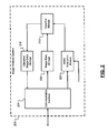
- the image analysis system 200 communicates with the visual inspection system 104 of FIG. 1 via, for example, a communication interface 204.
- the image analysis system 200 may be integrated with the visual inspection system 104 (e.g., integrated with the display device 112, the inspection camera 108, and/or another device of the visual inspection system 104).
- the communication interface 204 receives image data from the visual inspection system 104.
- the image data is stored in image data storage 208.
- the image data storage 208 includes non-volatile memory that stores the image data.
- the image data includes video data and/or still image data.
- a classifier module 212 identifies features corresponding to crossbores and/or lateral pipes in each frame of the image data and classifies each frame according to the identified features. For example, the classifier module 212 implements a classifier model that analyzes and classifies each frame according to features in the frame. For example only, each frame is assigned one or more labels including, but not limited to, "lateral pipe,” “no lateral pipe,” “crossbore,” and/or "no crossbore.” The classifier module 212 stores the classified image data in classified image data storage 216.
- the communication interface 204 provides the classified image data to the visual inspection system 200 or to another device or a user (e.g., upon request).
- the image analysis system 200 includes a model adaptation module 220 that generates and adapts the classifier model of the classifier module 212.
- the model adaptation module generates and adapts the classifier model based on, for example, feedback data received via the communication interface 204 and/or training data.
- the feedback data includes feedback provided by an operator/user of the visual inspection system 104 regarding the classified image data. For example, the operator views the classified image data and the identified features and provides feedback indicative of the accuracy of the classified image data (e.g., whether the labels assigned to a frame of the classified image data are correct).
- the training data may include training image data (e.g., training videos) having various combinations of features (e.g., crossbore, no crossbore, lateral pipe, and/or no lateral pipe).
- the model adaptation module 220 extracts the features from the training image data and labels each frame accordingly (e.g., using the model), and stores classified training data.
- the model adaptation module 220 compares the classified training data to test data indicative of actual features of the training image data to evaluate the results of the model.
- the model adaptation module 220 updates the model used by the classifier module 212 according to the results.
- an example model adaptation module 300 includes a training image data classifier module 304, a training and test data storage module 308, and a result evaluation module 312.
- the training image data classifier module receives the training image data and the feedback data, extracts features indicative of crossbores and/or lateral pipes from the training image data, and provides classified training image data to the training and test data storage module 308.
- the classified training image data may be separated into two sets, including a first set of training image data including features corresponding to crossbores and a second set of training image data including features corresponding to lateral pipes.
- the result evaluation module 312 compares the classified training image data to the test data and evaluates the performance of the model based on the comparison.
- An output (e.g., a model adjustment signal) of the result evaluation module 312 is indicative of the performance of the model and is provided to the classifier module 212 to adjust the model accordingly.
- the training image data may include, for example, a plurality of videos arranged in different sets including different respective features.
- the training image data may include a lateral inspection training set including a first plurality of videos with lateral pipes and a second plurality of videos with no lateral pipes.
- the training image data may also include a crossbore inspection training set including a first plurality of videos with crossbores and a second plurality of videos with no crossbores.
- the training image and data classifier module 304 extracts, for each of lateral pipes and crossbores, one or more features that may indicate a lateral pipe or a crossbore.
- the features may include, but are not limited to, parallel lines, color information, K-means clustering, and/or a discretized histogram of gradient magnitude.
- parallel lines in a frame of image data may indicate a lateral pipe.
- the classifier module 304 may implement an edge detector to detect Hough lines in the image data, select one of the Hough lines L1 (e.g., a strongest one of the Hough lines), and select a strongest one of the Hough lines L2 that is parallel to L1 (e.g., within a threshold such as 5° of L1).
- Perspective analysis may be applied in situations where the pipe may run in the direction of the camera, resulting in lines that are not parallel in the actual image data.
- Probability that the lines L1 and L2 correspond to a lateral pipe may be adjusted using Kalman filter tracking.
- the Kalman filter tracking may track the suspected lateral pipe from an initial detection point to predict an end position of the pipe. If the predicted end position corresponds to actual detected features in the frame, then the frame may include a lateral pipe.
- the color information may indicate a lateral pipe and/or a crossbore.
- the training image and data classifier module 304 may implement an HSV histogram to identify amounts of selected colors (e.g., colors corresponding to known colors of certain types of utility pipes) in portions of the frame of image data.
- the K-means clustering may indicate a lateral pipe and/or a crossbore.
- a single Gaussian distribution (e.g., on hue) on a histogram may correspond to no crossbore
- a double Gaussian distribution (e.g., on hue) on a histogram may correspond to a crossbore.
- the discretized histogram of gradient magnitude may be used for edge detection and are indicative of both a lateral pipe and a crossbore.
- the discretized histogram may be calculated after a Gauss Blur and edge detector (e.g., a Canny edge detector) are applied to remove noise.
- edge detector e.g., a Canny edge detector
- peaks above a threshold indicate relatively strong edges.
- the training image and data classifier module 304 labels (i.e., classifies, via operator/user input) each of the frames.
- the labels may include "lateral pipe,” “no lateral pipe,” “crossbore,” and/or “no crossbore,” and may include sub-labels such as “approaching lateral pipe,” “approaching crossbore,” and soil type (e.g., sand, clay, rocky, etc.).
- the labels are applied manually (i.e., by a human operator/user). In other words, the operator views each frame and labels the frame based on visible features in the image.
- the model adaptation module 300 assigns a probability that that feature corresponds to a crossbore, no crossbore, a lateral pipe, and/or no lateral pipe based on the labels assigned by the operator. For example, the classifier module 304 assigns a probability that two strong parallel lines indicate a lateral pipe based on how many times the corresponding extracted feature (e.g., two strong parallel lines) was ultimately labeled as a lateral pipe by the operator.
- the classifier module 304 assigns a probability that two strong parallel lines do not correspond to a lateral pipe (i.e., no lateral pipe) based on how many times the corresponding extracted feature (e.g., two strong parallel lines) was ultimately labeled as no lateral pipe by the operator. Accordingly, each of the extracted features is assigned a respective probability.
- the classified training image data is then stored according to the labels. For example, each frame may be indexed by a frame number
- the test data is stored along with the training image data in the training and test data storage 308.
- the test data corresponds to fewer test data frames than the training image data. In other words, a larger portion of the image data stored in the training and test data storage 308 corresponds to the training image data than to the test data.
- the training image data is labeled by the operator as described above. In contrast, the test data is not labeled by the operator. Instead, the test data, which may include image data frames identical to a portion of the training image data, is analyzed according to the model.
- the results of analyzing the test data i.e., assigned labels and/or probabilities
- the model can be adjusted based on the accuracy.
- the result evaluation module 312 may determine an error rate associated with the evaluation of the test data, and/or an average error rate associated with a plurality of evaluations.
- the classifier module 212 analyzes the image data received from the image data storage 208 (i.e., extracts features from the images) and calculates, based on the extracted features and the training image data, probabilities that each frame includes a crossbore, no crossbore, a lateral pipe, or no lateral pipe.
- a probability that a frame includes a crossbore may include a combination of each of the probabilities that each of the features detected in the frame corresponds to a crossbore.
- a probability that a frame includes no crossbore may include a combination of each of the probabilities that each of the features detected in the frame corresponds to no crossbore.
- a probability that a frame includes a lateral pipe may include a combination of each of the probabilities that each of the features detected in the frame corresponds to a lateral pipe.
- a probability that a frame includes no lateral pipe may include a combination of each of the probabilities that each of the features detected in the frame corresponds to no lateral pipe.
- the probability may be calculated according to various methods, such as a Na ⁇ ve Bayes Classification.
- the Na ⁇ ve Bayes Classification may calculate a probability that a frame includes a lateral pipe based on the probabilities assigned to the parallel lines detection the color information, and the discretized histogram. If the calculated probability is greater than a threshold, then the classifier module 212 assigns a lateral pipe label to the frame.
- the threshold may be fixed (e.g., 50%), and/or may be adjustable to be more sensitive (i.e., lowered) or less sensitive (i.e., raised).
- the classifier module 212 determines whether to assign labels for no lateral pipe, a crossbore, and no crossbore to the frame in a similar manner.
- the probability may simply be a sum, an average, or any other combination of the probabilities of the respective features.
- all of the probabilities for assigning labels may be less than the respective thresholds. Accordingly, a frame may not qualify for any of the labels.
- the classifier module 212 may perform a "nearest neighbor" calculation to assign one or more labels. For example, the classifier module 212 may determine, based on the extracted features, which training image data frame most closely resembles the frame. The classifier module 212 labels the frame based on the labels assigned to the closest training image data frame.
- module may refer to, be part of, or include an Application Specific Integrated Circuit (ASIC); a discrete circuit; an integrated circuit; a combinational logic circuit; a field programmable gate array (FPGA); a processor (shared, dedicated, or group) that executes code; other suitable hardware components that provide the described functionality; or a combination of some or all of the above, such as in a system-on-chip.
- ASIC Application Specific Integrated Circuit
- FPGA field programmable gate array
- the term module may include memory (shared, dedicated, or group) that stores code executed by the processor.
- code may include software, firmware, and/or microcode, and may refer to programs, routines, functions, classes, and/or objects.
- shared means that some or all code from multiple modules may be executed using a single (shared) processor. In addition, some or all code from multiple modules may be stored by a single (shared) memory.
- group means that some or all code from a single module may be executed using a group of processors. In addition, some or all code from a single module may be stored using a group of memories.
- the apparatuses and methods described herein may be partially or fully implemented by one or more computer programs executed by one or more processors.
- the computer programs include processor-executable instructions that are stored on at least one non-transitory tangible computer readable medium.
- the computer programs may also include and/or rely on stored data.
- Non-limiting examples of the non-transitory tangible computer readable medium include nonvolatile memory, volatile memory, magnetic storage, and optical storage.
Landscapes
- Engineering & Computer Science (AREA)
- Physics & Mathematics (AREA)
- Mining & Mineral Resources (AREA)
- Geology (AREA)
- Life Sciences & Earth Sciences (AREA)
- Computer Vision & Pattern Recognition (AREA)
- Quality & Reliability (AREA)
- Theoretical Computer Science (AREA)
- General Physics & Mathematics (AREA)
- Geochemistry & Mineralogy (AREA)
- Environmental & Geological Engineering (AREA)
- Fluid Mechanics (AREA)
- General Life Sciences & Earth Sciences (AREA)
- Geophysics (AREA)
- Signal Processing (AREA)
- Multimedia (AREA)
- Investigating Materials By The Use Of Optical Means Adapted For Particular Applications (AREA)
- Image Analysis (AREA)
- Geophysics And Detection Of Objects (AREA)
Applications Claiming Priority (2)
| Application Number | Priority Date | Filing Date | Title |
|---|---|---|---|
| US201261738103P | 2012-12-17 | 2012-12-17 | |
| US13/801,330 US9219886B2 (en) | 2012-12-17 | 2013-03-13 | Method and apparatus for analyzing image data generated during underground boring or inspection activities |
Publications (1)
| Publication Number | Publication Date |
|---|---|
| EP2743447A1 true EP2743447A1 (en) | 2014-06-18 |
Family
ID=49766866
Family Applications (1)
| Application Number | Title | Priority Date | Filing Date |
|---|---|---|---|
| EP13195562.7A Withdrawn EP2743447A1 (en) | 2012-12-17 | 2013-12-03 | Method and apparatus for analyzing image data generated during underground boring or inspection activities |
Country Status (6)
| Country | Link |
|---|---|
| US (1) | US9219886B2 (https=) |
| EP (1) | EP2743447A1 (https=) |
| JP (1) | JP6005026B2 (https=) |
| CN (1) | CN103867186B (https=) |
| CA (1) | CA2834268A1 (https=) |
| RU (1) | RU2013155978A (https=) |
Cited By (8)
| Publication number | Priority date | Publication date | Assignee | Title |
|---|---|---|---|---|
| CN109583486A (zh) * | 2018-11-21 | 2019-04-05 | 银河水滴科技(北京)有限公司 | 一种检测待测环境异常区域的方法及装置 |
| US10427734B2 (en) | 2017-07-18 | 2019-10-01 | General Electric Company | Omnidirectional traction module for a robot |
| US10427290B2 (en) | 2017-07-18 | 2019-10-01 | General Electric Company | Crawler robot for in situ gap inspection |
| US10434641B2 (en) | 2017-07-18 | 2019-10-08 | General Electric Company | In situ gap inspection robot system and method |
| US10596713B2 (en) | 2017-07-18 | 2020-03-24 | General Electric Company | Actuated sensor module and method for in situ gap inspection robots |
| US10603802B2 (en) | 2017-07-18 | 2020-03-31 | General Electric Company | End region inspection module and method for in situ gap inspection robot system |
| US12038119B2 (en) | 2019-08-20 | 2024-07-16 | Ge Infrastructure Technology Llc | Sensor interface module with scissor lift for plurality of sensors, and visual inspection module with dual view paths for robot |
| US12151751B2 (en) | 2019-08-20 | 2024-11-26 | Ge Infrastructure Technology Llc | Traction module for robot with variable extension positions |
Families Citing this family (17)
| Publication number | Priority date | Publication date | Assignee | Title |
|---|---|---|---|---|
| US20140292616A1 (en) * | 2013-03-28 | 2014-10-02 | Nvidia Corporation | Computer monitor equalization using handheld device |
| JP6428089B2 (ja) | 2014-09-24 | 2018-11-28 | 日亜化学工業株式会社 | 発光装置 |
| US10469511B2 (en) * | 2016-03-28 | 2019-11-05 | Cisco Technology, Inc. | User assistance coordination in anomaly detection |
| KR101782363B1 (ko) * | 2016-05-23 | 2017-09-27 | (주)에이앤아이 | 데이터 밸런싱을 통한 학습기반의 비전검사 방법 |
| CN106157182B (zh) * | 2016-07-07 | 2021-03-23 | 云南省交通规划设计研究院有限公司 | 一种公路隧道仰拱质量缺陷程度的判定方法 |
| EP3340106B1 (en) * | 2016-12-23 | 2023-02-08 | Hexagon Technology Center GmbH | Method and system for assigning particular classes of interest within measurement data |
| KR102579904B1 (ko) * | 2018-01-31 | 2023-09-19 | 삼성전자주식회사 | 비전 검사 관리 방법 및 비전 검사 시스템 |
| WO2019213534A1 (en) | 2018-05-04 | 2019-11-07 | Hydromax USA, LLC | Pipe inspection systems and methods |
| US12229841B2 (en) * | 2018-06-27 | 2025-02-18 | Hydromax USA, LLC | Cross-bore risk assessment and risk management tool |
| CN109145951B (zh) * | 2018-07-23 | 2022-04-12 | 昆明理工大学 | 一种基于贝叶斯网络的隧道衬砌结构服役状况评价方法 |
| CA3115746C (en) * | 2018-10-24 | 2023-08-29 | Fujitsu Frontech Limited | Banknote inspection device, banknote inspection method, and banknote inspection program |
| US11592594B2 (en) * | 2020-04-13 | 2023-02-28 | X Development Llc | Subsurface lithological model with machine learning |
| BR102020012943A2 (pt) * | 2020-06-24 | 2022-01-04 | Petróleo Brasileiro S.A. - Petrobras | Script computacional para tratamento de imagens e sua aplicação em método para determinação de image fáceis |
| CN113256551B (zh) * | 2021-01-21 | 2023-03-14 | 中国煤炭科工集团太原研究院有限公司 | 基于机器视觉的巷道顶板刚带钻孔识别定位系统及方法 |
| FR3122924B1 (fr) * | 2021-05-12 | 2024-11-15 | Veolia Environnement | Système d’identification de défaut dans une canalisation |
| DE102022203605A1 (de) * | 2022-04-11 | 2023-10-12 | Robert Bosch Gesellschaft mit beschränkter Haftung | Verfahren für ein Detektionsgerät; Detektionsgerät |
| CN117150691B (zh) * | 2023-08-30 | 2024-12-27 | 广州地铁设计研究院股份有限公司 | 钻探施工过程中的地下管线识别方法、装置及存储介质 |
Citations (2)
| Publication number | Priority date | Publication date | Assignee | Title |
|---|---|---|---|---|
| US20030118230A1 (en) * | 2001-12-22 | 2003-06-26 | Haoshi Song | Coiled tubing inspection system using image pattern recognition |
| EP2192538A2 (en) * | 2008-11-21 | 2010-06-02 | Emerson Electric Co. | System for sharing video captured at jobsite |
Family Cites Families (19)
| Publication number | Priority date | Publication date | Assignee | Title |
|---|---|---|---|---|
| JPS61193090A (ja) * | 1985-02-22 | 1986-08-27 | Nippon Kokan Kk <Nkk> | 地中障害物検知器 |
| US4974168A (en) | 1988-04-19 | 1990-11-27 | Cherne Industries, Inc. | Automatic pipeline data collection and display system |
| US5331550A (en) | 1991-03-05 | 1994-07-19 | E. I. Du Pont De Nemours And Company | Application of neural networks as an aid in medical diagnosis and general anomaly detection |
| DE4328031A1 (de) | 1992-09-24 | 1994-03-31 | Deutsche Aerospace | Verfahren zum Erkennen einer Fehlstelle |
| US5454276A (en) | 1993-07-30 | 1995-10-03 | Wernicke; Timothy K. | Multi-directional magnetic flux pipe inspection apparatus and method |
| FR2712663B1 (fr) | 1993-11-18 | 1996-01-19 | Val De Marne General Conseil | Appareil d'inspection de l'état physique de canalisations non accessibles ou visitables par l'homme. |
| JP2741653B2 (ja) * | 1994-06-03 | 1998-04-22 | トシマ建設工業株式会社 | 薬液注入用削孔管 |
| US5742517A (en) | 1995-08-29 | 1998-04-21 | Integrated Computer Utilities, Llc | Method for randomly accessing stored video and a field inspection system employing the same |
| US6175380B1 (en) | 1996-08-28 | 2001-01-16 | Peninsular Technologies, Llc | Method for randomly accessing stored imagery and a field inspection system employing the same |
| US5892163A (en) | 1998-01-27 | 1999-04-06 | Geophysical Survey Systems, Inc. | Sewer and pipeline inspection transporter tool |
| US6239593B1 (en) | 1998-09-21 | 2001-05-29 | Southwest Research Institute | Method and system for detecting and characterizing mechanical damage in pipelines using nonlinear harmonics techniques |
| US6650779B2 (en) | 1999-03-26 | 2003-11-18 | Georgia Tech Research Corp. | Method and apparatus for analyzing an image to detect and identify patterns |
| US7215811B2 (en) | 2000-11-22 | 2007-05-08 | Osama Moselhi | Method and apparatus for the automated detection and classification of defects in sewer pipes |
| JPWO2003076916A1 (ja) | 2002-03-13 | 2005-07-07 | 株式会社バーナム | 埋設管路内検査装置とその方法及び埋設管路内コンクリート劣化検査方法 |
| US7181985B2 (en) | 2005-05-27 | 2007-02-27 | Breval Technical Services Limited | Conduit inspection apparatus and method |
| US8087311B2 (en) | 2007-02-28 | 2012-01-03 | Merlo Stephen A | Remote pipe inspection using a mounted camera and sensor |
| WO2011080590A2 (en) | 2009-12-30 | 2011-07-07 | Sewervue Technology Corp. | Apparatus and method for inspection of underground sewer pipes |
| US8988969B2 (en) | 2010-04-23 | 2015-03-24 | Underground Imaging Technologies, Inc. | Detection of cross bores involving buried utilities |
| WO2013012981A1 (en) | 2011-07-21 | 2013-01-24 | Emerson Electric Co. | Inspection system and method for use in underground boring operations |
-
2013
- 2013-03-13 US US13/801,330 patent/US9219886B2/en not_active Expired - Fee Related
- 2013-11-22 JP JP2013241605A patent/JP6005026B2/ja not_active Expired - Fee Related
- 2013-11-27 CA CA2834268A patent/CA2834268A1/en not_active Abandoned
- 2013-12-03 EP EP13195562.7A patent/EP2743447A1/en not_active Withdrawn
- 2013-12-13 CN CN201310684922.4A patent/CN103867186B/zh not_active Expired - Fee Related
- 2013-12-17 RU RU2013155978/08A patent/RU2013155978A/ru not_active Application Discontinuation
Patent Citations (2)
| Publication number | Priority date | Publication date | Assignee | Title |
|---|---|---|---|---|
| US20030118230A1 (en) * | 2001-12-22 | 2003-06-26 | Haoshi Song | Coiled tubing inspection system using image pattern recognition |
| EP2192538A2 (en) * | 2008-11-21 | 2010-06-02 | Emerson Electric Co. | System for sharing video captured at jobsite |
Non-Patent Citations (2)
| Title |
|---|
| NEWMAN T S ET AL: "A SURVEY OF AUTOMATED VISUAL INSPECTION", COMPUTER VISION AND IMAGE UNDERSTANDING, ACADEMIC PRESS, US, vol. 61, no. 2, 1 March 1995 (1995-03-01), pages 231 - 262, XP000644611, ISSN: 1077-3142, DOI: 10.1006/CVIU.1995.1017 * |
| SUNIL K SINHA: "Automated underground pipe inspection using a unified image processing and artificial intelligence methodology", 2000, A thesis presented to the University of Waterloo in fulfilment of the thesis requirement for the degree of Doctor of Philosophy in Civil Engineering and System Design Engineering, XP055114206, Retrieved from the Internet <URL:http://hdl.handle.net/10012/578> [retrieved on 20140415] * |
Cited By (8)
| Publication number | Priority date | Publication date | Assignee | Title |
|---|---|---|---|---|
| US10427734B2 (en) | 2017-07-18 | 2019-10-01 | General Electric Company | Omnidirectional traction module for a robot |
| US10427290B2 (en) | 2017-07-18 | 2019-10-01 | General Electric Company | Crawler robot for in situ gap inspection |
| US10434641B2 (en) | 2017-07-18 | 2019-10-08 | General Electric Company | In situ gap inspection robot system and method |
| US10596713B2 (en) | 2017-07-18 | 2020-03-24 | General Electric Company | Actuated sensor module and method for in situ gap inspection robots |
| US10603802B2 (en) | 2017-07-18 | 2020-03-31 | General Electric Company | End region inspection module and method for in situ gap inspection robot system |
| CN109583486A (zh) * | 2018-11-21 | 2019-04-05 | 银河水滴科技(北京)有限公司 | 一种检测待测环境异常区域的方法及装置 |
| US12038119B2 (en) | 2019-08-20 | 2024-07-16 | Ge Infrastructure Technology Llc | Sensor interface module with scissor lift for plurality of sensors, and visual inspection module with dual view paths for robot |
| US12151751B2 (en) | 2019-08-20 | 2024-11-26 | Ge Infrastructure Technology Llc | Traction module for robot with variable extension positions |
Also Published As
| Publication number | Publication date |
|---|---|
| US20140168408A1 (en) | 2014-06-19 |
| CA2834268A1 (en) | 2014-06-17 |
| RU2013155978A (ru) | 2015-06-27 |
| CN103867186A (zh) | 2014-06-18 |
| JP6005026B2 (ja) | 2016-10-12 |
| JP2014122887A (ja) | 2014-07-03 |
| US9219886B2 (en) | 2015-12-22 |
| CN103867186B (zh) | 2018-05-25 |
Similar Documents
| Publication | Publication Date | Title |
|---|---|---|
| US9219886B2 (en) | Method and apparatus for analyzing image data generated during underground boring or inspection activities | |
| Yu et al. | Automated detection of urban road manhole covers using mobile laser scanning data | |
| Lato et al. | Comparison of airborne laser scanning, terrestrial laser scanning, and terrestrial photogrammetry for mapping differential slope change in mountainous terrain | |
| US20200233060A1 (en) | Sensor data anomaly detection system and method for a vehicle | |
| KR102074462B1 (ko) | 적외선 영상분석을 이용한 싱크홀 탐지시스템 및 이를 이용한 싱크홀 탐지방법 | |
| Zhang et al. | Deep learning‐based automatic detection of muck types for earth pressure balance shield tunneling in soft ground | |
| WO2022047846A1 (zh) | 一种矿井顶板的异常监测方法及异常监测系统 | |
| KR101895835B1 (ko) | 지표 투과 레이더 탐사 시스템 | |
| US9399910B2 (en) | Inspection system and method for use in underground boring operations | |
| EA200600914A1 (ru) | Система и способ для определения местоположения аномалии в пласте, окружающем скважину | |
| US11543080B2 (en) | Automated pipeline construction modelling | |
| Liu et al. | Vision-based real-time lane marking detection and tracking | |
| CN111810768A (zh) | 基于分布式光纤传感的清管器行进状态监测方法及装置 | |
| CN210119237U (zh) | 路侧自动驾驶车辆定位导航系统 | |
| KR101643305B1 (ko) | 지하매설물 파손 위험 감지시스템 및 방법 | |
| Shin et al. | Enhancing Railway Maintenance Safety Using Open‐Source Computer Vision | |
| KR20220029396A (ko) | 딥러닝 모델을 이용한 암반 등급을 평가하는 자동화 장치 및 방법 | |
| Hurry et al. | Atmospheric monitoring and detection of fugitive emissions for Enhanced Oil Recovery | |
| US20230131412A1 (en) | System and method for continous and real-time locating and tracking scraper using uav | |
| Shen et al. | Integrated approach to machine guidance and operations monitoring in tunnel construction | |
| CN120577889A (zh) | 一种基于红外热成像的浅埋煤层地表导气裂缝识别方法 | |
| US20230107918A1 (en) | Excavator system for locating an underground utility line | |
| Fan et al. | Elevated high-precision mapping and localization technology for periodic inspections | |
| KR102546808B1 (ko) | 실시간 충돌사고 회피기능을 갖는 수평지향성 압입시스템 및 수평지향성 압입공법 | |
| JP2018091003A (ja) | 地中探査システム |
Legal Events
| Date | Code | Title | Description |
|---|---|---|---|
| PUAI | Public reference made under article 153(3) epc to a published international application that has entered the european phase |
Free format text: ORIGINAL CODE: 0009012 |
|
| 17P | Request for examination filed |
Effective date: 20131203 |
|
| AK | Designated contracting states |
Kind code of ref document: A1 Designated state(s): AL AT BE BG CH CY CZ DE DK EE ES FI FR GB GR HR HU IE IS IT LI LT LU LV MC MK MT NL NO PL PT RO RS SE SI SK SM TR |
|
| AX | Request for extension of the european patent |
Extension state: BA ME |
|
| R17P | Request for examination filed (corrected) |
Effective date: 20141105 |
|
| RBV | Designated contracting states (corrected) |
Designated state(s): AL AT BE BG CH CY CZ DE DK EE ES FI FR GB GR HR HU IE IS IT LI LT LU LV MC MK MT NL NO PL PT RO RS SE SI SK SM TR |
|
| 17Q | First examination report despatched |
Effective date: 20181024 |
|
| STAA | Information on the status of an ep patent application or granted ep patent |
Free format text: STATUS: THE APPLICATION IS DEEMED TO BE WITHDRAWN |
|
| 18D | Application deemed to be withdrawn |
Effective date: 20190305 |