EP2743423A1 - Bracing element - Google Patents
Bracing element Download PDFInfo
- Publication number
- EP2743423A1 EP2743423A1 EP13186222.9A EP13186222A EP2743423A1 EP 2743423 A1 EP2743423 A1 EP 2743423A1 EP 13186222 A EP13186222 A EP 13186222A EP 2743423 A1 EP2743423 A1 EP 2743423A1
- Authority
- EP
- European Patent Office
- Prior art keywords
- composite material
- bracing element
- element according
- bearing portion
- bracing
- Prior art date
- Legal status (The legal status is an assumption and is not a legal conclusion. Google has not performed a legal analysis and makes no representation as to the accuracy of the status listed.)
- Withdrawn
Links
- 239000002131 composite material Substances 0.000 claims abstract description 45
- 229920000642 polymer Polymers 0.000 claims description 11
- OKTJSMMVPCPJKN-UHFFFAOYSA-N Carbon Chemical compound [C] OKTJSMMVPCPJKN-UHFFFAOYSA-N 0.000 claims description 8
- 229910052799 carbon Inorganic materials 0.000 claims description 8
- 239000000835 fiber Substances 0.000 claims description 8
- 239000003365 glass fiber Substances 0.000 claims description 8
- 239000004743 Polypropylene Substances 0.000 claims description 4
- 230000005540 biological transmission Effects 0.000 claims description 4
- -1 polypropylene Polymers 0.000 claims description 4
- 229920001155 polypropylene Polymers 0.000 claims description 4
- 239000012212 insulator Substances 0.000 claims description 3
- 239000002861 polymer material Substances 0.000 claims description 3
- 229910052751 metal Inorganic materials 0.000 description 12
- 239000002184 metal Substances 0.000 description 12
- 239000000463 material Substances 0.000 description 4
- 239000011810 insulating material Substances 0.000 description 3
- 238000000034 method Methods 0.000 description 3
- 238000000465 moulding Methods 0.000 description 3
- 230000015572 biosynthetic process Effects 0.000 description 2
- 230000000694 effects Effects 0.000 description 2
- 238000009413 insulation Methods 0.000 description 2
- 239000000853 adhesive Substances 0.000 description 1
- 238000004026 adhesive bonding Methods 0.000 description 1
- 230000001070 adhesive effect Effects 0.000 description 1
- 230000004075 alteration Effects 0.000 description 1
- 230000000712 assembly Effects 0.000 description 1
- 238000000429 assembly Methods 0.000 description 1
- 239000004020 conductor Substances 0.000 description 1
- 238000010276 construction Methods 0.000 description 1
- 238000001723 curing Methods 0.000 description 1
- 238000009408 flooring Methods 0.000 description 1
- 229910001092 metal group alloy Inorganic materials 0.000 description 1
- 150000002739 metals Chemical class 0.000 description 1
- 238000012986 modification Methods 0.000 description 1
- 230000004048 modification Effects 0.000 description 1
- 238000003466 welding Methods 0.000 description 1
Images


Classifications
-
- E—FIXED CONSTRUCTIONS
- E04—BUILDING
- E04C—STRUCTURAL ELEMENTS; BUILDING MATERIALS
- E04C3/00—Structural elongated elements designed for load-supporting
- E04C3/02—Joists; Girders, trusses, or trusslike structures, e.g. prefabricated; Lintels; Transoms; Braces
- E04C3/29—Joists; Girders, trusses, or trusslike structures, e.g. prefabricated; Lintels; Transoms; Braces built-up from parts of different material, i.e. composite structures
- E04C3/291—Joists; Girders, trusses, or trusslike structures, e.g. prefabricated; Lintels; Transoms; Braces built-up from parts of different material, i.e. composite structures with apertured web
-
- E—FIXED CONSTRUCTIONS
- E04—BUILDING
- E04C—STRUCTURAL ELEMENTS; BUILDING MATERIALS
- E04C3/00—Structural elongated elements designed for load-supporting
- E04C3/02—Joists; Girders, trusses, or trusslike structures, e.g. prefabricated; Lintels; Transoms; Braces
- E04C3/04—Joists; Girders, trusses, or trusslike structures, e.g. prefabricated; Lintels; Transoms; Braces of metal
- E04C3/08—Joists; Girders, trusses, or trusslike structures, e.g. prefabricated; Lintels; Transoms; Braces of metal with apertured web, e.g. with a web consisting of bar-like components; Honeycomb girders
-
- E—FIXED CONSTRUCTIONS
- E04—BUILDING
- E04B—GENERAL BUILDING CONSTRUCTIONS; WALLS, e.g. PARTITIONS; ROOFS; FLOORS; CEILINGS; INSULATION OR OTHER PROTECTION OF BUILDINGS
- E04B1/00—Constructions in general; Structures which are not restricted either to walls, e.g. partitions, or floors or ceilings or roofs
- E04B1/62—Insulation or other protection; Elements or use of specified material therefor
- E04B1/74—Heat, sound or noise insulation, absorption, or reflection; Other building methods affording favourable thermal or acoustical conditions, e.g. accumulating of heat within walls
- E04B1/76—Heat, sound or noise insulation, absorption, or reflection; Other building methods affording favourable thermal or acoustical conditions, e.g. accumulating of heat within walls specifically with respect to heat only
- E04B1/7654—Heat, sound or noise insulation, absorption, or reflection; Other building methods affording favourable thermal or acoustical conditions, e.g. accumulating of heat within walls specifically with respect to heat only comprising an insulating layer, disposed between two longitudinal supporting elements, e.g. to insulate ceilings
-
- E—FIXED CONSTRUCTIONS
- E04—BUILDING
- E04C—STRUCTURAL ELEMENTS; BUILDING MATERIALS
- E04C3/00—Structural elongated elements designed for load-supporting
- E04C3/02—Joists; Girders, trusses, or trusslike structures, e.g. prefabricated; Lintels; Transoms; Braces
- E04C3/12—Joists; Girders, trusses, or trusslike structures, e.g. prefabricated; Lintels; Transoms; Braces of wood, e.g. with reinforcements, with tensioning members
- E04C3/18—Joists; Girders, trusses, or trusslike structures, e.g. prefabricated; Lintels; Transoms; Braces of wood, e.g. with reinforcements, with tensioning members with metal or other reinforcements or tensioning members
-
- E—FIXED CONSTRUCTIONS
- E04—BUILDING
- E04C—STRUCTURAL ELEMENTS; BUILDING MATERIALS
- E04C3/00—Structural elongated elements designed for load-supporting
- E04C3/02—Joists; Girders, trusses, or trusslike structures, e.g. prefabricated; Lintels; Transoms; Braces
- E04C3/12—Joists; Girders, trusses, or trusslike structures, e.g. prefabricated; Lintels; Transoms; Braces of wood, e.g. with reinforcements, with tensioning members
- E04C3/18—Joists; Girders, trusses, or trusslike structures, e.g. prefabricated; Lintels; Transoms; Braces of wood, e.g. with reinforcements, with tensioning members with metal or other reinforcements or tensioning members
- E04C3/185—Synthetic reinforcements
-
- E—FIXED CONSTRUCTIONS
- E04—BUILDING
- E04C—STRUCTURAL ELEMENTS; BUILDING MATERIALS
- E04C3/00—Structural elongated elements designed for load-supporting
- E04C3/02—Joists; Girders, trusses, or trusslike structures, e.g. prefabricated; Lintels; Transoms; Braces
- E04C3/29—Joists; Girders, trusses, or trusslike structures, e.g. prefabricated; Lintels; Transoms; Braces built-up from parts of different material, i.e. composite structures
- E04C3/292—Joists; Girders, trusses, or trusslike structures, e.g. prefabricated; Lintels; Transoms; Braces built-up from parts of different material, i.e. composite structures the materials being wood and metal
-
- F—MECHANICAL ENGINEERING; LIGHTING; HEATING; WEAPONS; BLASTING
- F16—ENGINEERING ELEMENTS AND UNITS; GENERAL MEASURES FOR PRODUCING AND MAINTAINING EFFECTIVE FUNCTIONING OF MACHINES OR INSTALLATIONS; THERMAL INSULATION IN GENERAL
- F16B—DEVICES FOR FASTENING OR SECURING CONSTRUCTIONAL ELEMENTS OR MACHINE PARTS TOGETHER, e.g. NAILS, BOLTS, CIRCLIPS, CLAMPS, CLIPS OR WEDGES; JOINTS OR JOINTING
- F16B15/00—Nails; Staples
- F16B15/0023—Nail plates
- F16B15/003—Nail plates with teeth cut out from the material of the plate
- F16B15/0046—Nail plates with teeth cut out from the material of the plate from the body of the plate
-
- E—FIXED CONSTRUCTIONS
- E04—BUILDING
- E04C—STRUCTURAL ELEMENTS; BUILDING MATERIALS
- E04C3/00—Structural elongated elements designed for load-supporting
- E04C3/02—Joists; Girders, trusses, or trusslike structures, e.g. prefabricated; Lintels; Transoms; Braces
- E04C2003/026—Braces
-
- Y—GENERAL TAGGING OF NEW TECHNOLOGICAL DEVELOPMENTS; GENERAL TAGGING OF CROSS-SECTIONAL TECHNOLOGIES SPANNING OVER SEVERAL SECTIONS OF THE IPC; TECHNICAL SUBJECTS COVERED BY FORMER USPC CROSS-REFERENCE ART COLLECTIONS [XRACs] AND DIGESTS
- Y02—TECHNOLOGIES OR APPLICATIONS FOR MITIGATION OR ADAPTATION AGAINST CLIMATE CHANGE
- Y02A—TECHNOLOGIES FOR ADAPTATION TO CLIMATE CHANGE
- Y02A30/00—Adapting or protecting infrastructure or their operation
-
- Y—GENERAL TAGGING OF NEW TECHNOLOGICAL DEVELOPMENTS; GENERAL TAGGING OF CROSS-SECTIONAL TECHNOLOGIES SPANNING OVER SEVERAL SECTIONS OF THE IPC; TECHNICAL SUBJECTS COVERED BY FORMER USPC CROSS-REFERENCE ART COLLECTIONS [XRACs] AND DIGESTS
- Y02—TECHNOLOGIES OR APPLICATIONS FOR MITIGATION OR ADAPTATION AGAINST CLIMATE CHANGE
- Y02B—CLIMATE CHANGE MITIGATION TECHNOLOGIES RELATED TO BUILDINGS, e.g. HOUSING, HOUSE APPLIANCES OR RELATED END-USER APPLICATIONS
- Y02B30/00—Energy efficient heating, ventilation or air conditioning [HVAC]
- Y02B30/90—Passive houses; Double facade technology
Definitions
- the invention relates to a bracing element for spacing timber chords in a joist or truss.
- the invention relates to a bracing element capable of minimizing thermal bridging through joists or trusses.
- the invention further relates to a joist comprising one or more bracing elements according to the invention.
- Bracing elements for connecting and spacing parallel chords of a joist or truss are known in the building and construction industry.
- bracing elements formed of metal are well known, such metal bracing elements being attached to the parallel chords of the joist or truss so as to form the web between the parallel chords.
- An example of a known bracing element 10 (V-shaped) is shown in Figure 1 .
- bracing element-type joists 12 or trusses are commonly used in floor and roof structures and the like (i.e. wall structures). Typically, as shown in Figures 2 and 3 , they include an upper timber chord 14, a lower timber chord 16 and one or more bracing elements 10, typically metal bracing elements, extending in diagonal or vertical orientation between the upper and lower chords 14, 16.
- bracing element 10 Various configurations of bracing element 10 are known, and these include I-shaped, V-shaped, S-shaped and W-shaped elements.
- chord joists In use, parallel chord joists are arranged with an upper timber chord 14 positioned at a predetermined distance above, and generally parallel to, a lower timber chord 16. Bracing elements 10 extending between the chords 14, 16 connect the chords 14, 16 and maintain them in the required spaced relation. Open, bracing element-type joists 12 or trusses provide the advantage that utilities such as piping and wiring may be passed through the spaces between chords.
- the joist 12 may comprise a plurality of bracing elements 10 forming the web of the joist.
- the joist 12 may comprise bracing elements 10 having one or more different shapes.
- the joist 12 may comprise bracing elements 10 attached at one side of the timber chords 14, 16, alternatively, the joist 12 may comprise bracing elements 10 attached at both sides of the timber chords (see Figure 3 ).
- the bracing elements 10 may be in parallel opposition to one another or may be staggered in longitudinal relation to one another.
- Bracing elements 10 may be attached to the chords 14, 16 by a number of methods, but are commonly attached by connector plates (or nail plates) 18 having protruding teeth 20 that embed in the wooden chord 14, 16.
- the connector plates 18 are attached to a side surface of the, or each, chord 14, 16 of the joist 12.
- the connector plates 18 or nail plates are typically formed integrally with an elongate spacing portion 22 of the bracing element 10.
- the elongate spacing portion 22 is the bearing portion that transfers and withstands forces between the upper and lower timber chords 14, 16 via the connector plates 18.
- bracing elements are thermally conductive materials the maximum possible conductive energy transfer is provided across the flooring and/or roof structures, despite insulating material that may be placed in the space between the chords 14, 16. This energy loss is also known as "thermal bridging".
- thermal bridging is created when materials that are poor thermal insulators, such as the known metal bracing elements 10, come into contact, allowing heat to flow from a higher temperature environment T 1 to a lower temperature environment T 2 (heat transfer is illustrated by black and white arrows) through the path of least thermal resistance (i.e. metal bracing element 10) leading to significantly increased heat losses.
- bracing element and/or joist that is capable of minimizing the "thermal bridging" effect and improve the general energy efficiency of structural buildings assemblies, such as any heated or cooled building enclosure or building envelope.
- Preferred embodiments of the invention seek to overcome one or more of the above disadvantages of the prior art.
- a bracing element for spacing timber elements in a truss or joist, the bracing element comprising at least two connector plates connected to and spaced apart from one another by at least one elongate spacing portion, wherein at least part of said elongate spacing portion is made from composite material.
- said composite material may be a thermal insulator.
- the thermally insulating part of the elongate spacing portion is adapted to disrupt or decrease the heat conduction path between the at least two connector plates and therefore prevent or minimize "thermal bridging" between the spaced apart chords, contributing to maximizing the energy efficiency of a building structure.
- the composite material may further be adapted to minimize acoustic transmission between said at least two connector plates. This provides the further advantage of minimizing acoustic transmission through the joists, therefore contributing to minimizing the noise level in a building structure.
- the composite material may extend along the full length of said elongate spacing portion.
- the elongate spacing portion may comprise a bearing portion that is integral with said at least two connector plates, the bearing portion being at least partially encased by said composite material, so as to minimize thermal losses through said bearing portion.
- the elongate spacing portion may comprise a bearing portion that is integral with said at least two connector plates and which is sandwiched between said composite material, so as to minimize thermal losses through said bearing portion.
- the elongate spacing portion may comprise a bearing portion that is coupled to said at least two connector plates and which is formed from said composite material. In the latter alternative arrangement, the bearing portion extends between the at least two connector plates and is connected to each of the at least two connector plates.
- said composite material may be any one of a polymer material, a polymer composite material, carbon fibre, carbon fibre composite material and glass fibre or glass fibre composite material.
- the polymer and/or polymer composite material may be polypropylene and/or polypropylene composite material, respectively.
- a joist comprising first and second timber chords in spaced apart parallel relation and at least one bracing element according to the first aspect of the present invention, which is attached to said first and second timber chords at a surface thereof.
- a first embodiment of the bracing element 100 of the present invention comprises an elongate spacing portion 102, extending between two nail plates 104.
- Nail plates for attaching bracing elements to the timber chords of joists are known in the art and are commonly used to attach metal bracing elements to timber chords. It will, however, be apparent that alternative known attachment means suitable for attaching a bracing element to a timber joist, such as nails, screws, staples and the like, may be employed in the invention.
- the elongate spacing portion 102 comprises a bearing portion 106 integrally formed with the two nail plates 104 and encased by a composite material 108, such as, for example, any thermally insulating polymer or polymer composite, carbon fibre material or carbon fibre composite, or any glass fibre or glass fibre composite.
- a composite material 108 such as, for example, any thermally insulating polymer or polymer composite, carbon fibre material or carbon fibre composite, or any glass fibre or glass fibre composite.
- any other thermally insulating material may be used to encase the bearing portion 106 of the elongate spacing portion 102.
- the nail plates 104 and integrally formed bearing portion 106 are made from a metal or metal alloy.
- the bearing portion 106 is fully embedded in the composite material 108, either via a moulding process, where the composite material 108 is moulded around the whole or at least part of the bearing portion 106.
- all or at least part of the bearing portion 106 may be encased by the composite material 108 by simply attaching the composite material around the bearing portion 106, using an adhesive or any other mechanical fixture means.
- the composite material 108 extends along the total length of the bearing portion 106 (i.e. from upper nail plate 104 to lower nail plate 104) in order to maximize thermal insulation of the bearing portion 106.
- any other length of composite material 108 may be used to improve the thermal insulation of the bearing portion 106.
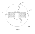
- Figure 6 shows a magnified sectional view along A-A of the bracing element 100, where the bearing portion 106 (e.g. a double flanged metal plate) is embedded in a composite material 108 via a moulding process.
- the bearing portion 106 of the bracing element 100 is simple placed in a hot polymer bath until the bearing portion 106 is fully enclosed by the liquefied polymer material and then cooled / cured too harden the composite material around the bearing portion 106.
- a second embodiment of the bracing element 200 of the present invention comprises an elongate spacing portion 202, extending between two nail plates 204.
- Nail plates for attaching bracing elements to the timber chords of joists are known in the art and are commonly used to attach metal bracing elements to timber chords. It will, however, be apparent that alternative known attachment means suitable for attaching a bracing element to a timber joist, such as nails, screws, staples and the like, may be employed in the invention.
- the elongate spacing portion 202 is a one-piece link-member attachable to the upper and lower nail plate 204 so as to form a structurally reliable bracing element 200.
- the elongate spacing portion 202 is made from a thermally insulating composite material, such as, for example, any thermally insulating polymer or polymer composite, carbon fibre material or carbon fibre composite, or any glass fibre or glass fibre composite. However, it is understood by the person skilled in the art that any other thermally insulating material may be used.
- the use of thermally insulating composite material and/or acoustically dampening material as link between the upper and lower nail plate 204 minimizes or even eliminates any "thermal bridging" and/or acoustic transmission between the upper and lower nail plate 204.
- the elongate spacing portion 202 is attached to respective nail plates 204 via a combination of a guided form-fit, using flange portions 206 to prevent any pivotal movement between the nail plate 204 and the elongate spacing portion 202, and mechanical fastening, using rivets 208.
- any other suitable fastening / fixing / attachment means may be used to fixedly attach the nail plates 204 to the elongate spacing member 202.
- the elongate spacing member 202 may be mechanically fastened to respective nail plates 204 using any number of screws or bolts, welding, moulding, adhesive bonding, curing or any combination thereof.
- Figure 8 shows a magnified sectional view across C-C of the bracing element 200 shown in Figure (a), where the composite elongate spacing portion 202 is form fitted within the space defined by the flange portions 206 and the nail plate 204 and mechanically fastened using a rivet 208 through the elongate spacing portion 202 and the nail plate 204.
- any suitable shape and form of the elongate spacing member 202 may be used to form a bracing element 200.
- bracing elements 100, 200 are used to connect two chords and form a joist (not shown) according to the present invention.
- the bracing elements 100, 200 may be applied to one or both sides of the chords, and may be in parallel or in alternate formation to each other.
- only bracing elements 100 according to the first embodiment or only bracing elements 200 according to the second embodiment are used for any one joist assembly and/or building structure.
Landscapes
- Engineering & Computer Science (AREA)
- Architecture (AREA)
- Civil Engineering (AREA)
- Structural Engineering (AREA)
- Wood Science & Technology (AREA)
- Composite Materials (AREA)
- Life Sciences & Earth Sciences (AREA)
- Chemical & Material Sciences (AREA)
- General Engineering & Computer Science (AREA)
- Physics & Mathematics (AREA)
- Mechanical Engineering (AREA)
- Acoustics & Sound (AREA)
- Electromagnetism (AREA)
- Floor Finish (AREA)
Abstract
The invention provides a bracing element for spacing timber elements in a truss or joist, the bracing element comprising at least two connector plates connected to and spaced apart from one another by at least one elongate spacing portion, wherein at least part of the elongate spacing portion is made from composite material.
Description
- The invention relates to a bracing element for spacing timber chords in a joist or truss. In particular, though not exclusively, the invention relates to a bracing element capable of minimizing thermal bridging through joists or trusses. The invention further relates to a joist comprising one or more bracing elements according to the invention.
- Bracing elements for connecting and spacing parallel chords of a joist or truss are known in the building and construction industry. In particular, bracing elements formed of metal are well known, such metal bracing elements being attached to the parallel chords of the joist or truss so as to form the web between the parallel chords. An example of a known bracing element 10 (V-shaped) is shown in
Figure 1 . - Open, bracing element-
type joists 12 or trusses are commonly used in floor and roof structures and the like (i.e. wall structures). Typically, as shown inFigures 2 and 3 , they include anupper timber chord 14, alower timber chord 16 and one or morebracing elements 10, typically metal bracing elements, extending in diagonal or vertical orientation between the upper andlower chords - Various configurations of
bracing element 10 are known, and these include I-shaped, V-shaped, S-shaped and W-shaped elements. - In use, parallel chord joists are arranged with an
upper timber chord 14 positioned at a predetermined distance above, and generally parallel to, alower timber chord 16.Bracing elements 10 extending between thechords chords type joists 12 or trusses provide the advantage that utilities such as piping and wiring may be passed through the spaces between chords. - As shown in
Figure 2 and 3 , thejoist 12 may comprise a plurality ofbracing elements 10 forming the web of the joist. The joist 12 may comprisebracing elements 10 having one or more different shapes. Thejoist 12 may comprisebracing elements 10 attached at one side of thetimber chords joist 12 may comprisebracing elements 10 attached at both sides of the timber chords (seeFigure 3 ). In arrangements where thebracing elements 10 are attached at both sides of thetimber chords bracing elements 10 may be in parallel opposition to one another or may be staggered in longitudinal relation to one another. -
Bracing elements 10 may be attached to thechords teeth 20 that embed in thewooden chord connector plates 18 are attached to a side surface of the, or each,chord joist 12. Theconnector plates 18 or nail plates are typically formed integrally with anelongate spacing portion 22 of thebracing element 10. Theelongate spacing portion 22 is the bearing portion that transfers and withstands forces between the upper andlower timber chords connector plates 18. - However, since metals, such as used in the commonly known
bracing elements 10, are thermally conductive materials the maximum possible conductive energy transfer is provided across the flooring and/or roof structures, despite insulating material that may be placed in the space between thechords - As illustrated in
Figure 4 , "thermal bridging" is created when materials that are poor thermal insulators, such as the knownmetal bracing elements 10, come into contact, allowing heat to flow from a higher temperature environment T1 to a lower temperature environment T2 (heat transfer is illustrated by black and white arrows) through the path of least thermal resistance (i.e. metal bracing element 10) leading to significantly increased heat losses. - It would therefore be desirable to provide a bracing element and/or joist that is capable of minimizing the "thermal bridging" effect and improve the general energy efficiency of structural buildings assemblies, such as any heated or cooled building enclosure or building envelope.
- Preferred embodiments of the invention seek to overcome one or more of the above disadvantages of the prior art.
- According to a first aspect of the present invention, there is provided a bracing element for spacing timber elements in a truss or joist, the bracing element comprising at least two connector plates connected to and spaced apart from one another by at least one elongate spacing portion, wherein at least part of said elongate spacing portion is made from composite material. Advantageously, said composite material may be a thermal insulator.
- This provides the advantage that heat flow through the bracing element is prevented or at least minimized. In particular, the thermally insulating part of the elongate spacing portion is adapted to disrupt or decrease the heat conduction path between the at least two connector plates and therefore prevent or minimize "thermal bridging" between the spaced apart chords, contributing to maximizing the energy efficiency of a building structure.
- The composite material may further be adapted to minimize acoustic transmission between said at least two connector plates. This provides the further advantage of minimizing acoustic transmission through the joists, therefore contributing to minimizing the noise level in a building structure.
- Advantageously, the composite material may extend along the full length of said elongate spacing portion.
- The elongate spacing portion may comprise a bearing portion that is integral with said at least two connector plates, the bearing portion being at least partially encased by said composite material, so as to minimize thermal losses through said bearing portion. Alternatively, the elongate spacing portion may comprise a bearing portion that is integral with said at least two connector plates and which is sandwiched between said composite material, so as to minimize thermal losses through said bearing portion. Alternatively, the elongate spacing portion may comprise a bearing portion that is coupled to said at least two connector plates and which is formed from said composite material. In the latter alternative arrangement, the bearing portion extends between the at least two connector plates and is connected to each of the at least two connector plates.
- Advantageously, said composite material may be any one of a polymer material, a polymer composite material, carbon fibre, carbon fibre composite material and glass fibre or glass fibre composite material. Even more advantageously, the polymer and/or polymer composite material may be polypropylene and/or polypropylene composite material, respectively.
- According to a second aspect of the present invention, there is provided a joist comprising first and second timber chords in spaced apart parallel relation and at least one bracing element according to the first aspect of the present invention, which is attached to said first and second timber chords at a surface thereof.
- This provides the advantage of floor, roof and/or wall structures capable of minimizing "thermal bridging" and therefore improving thermal efficiency as well as acoustic dampening efficiency.
- Where the terms "upper", "lower", "uppermost", "lowermost" are used within the specification, they should be considered as no more than relative, as the bracing element of the invention may be used in any appropriate orientation.
- Preferred embodiments of the present invention will now be described, by way of example only and not in any limitative sense, with reference to the accompanying drawings, in which:
-
Figure 1 shows plan view of known metal bracing elements in a V-shape formation; -
Figures 2 shows a plan view of a joist having upper and lower chords spaced apart and connected by known metal bracing elements; -
Figure 3 shows a partial perspective view of a joist having upper and lower chords and bracing elements attached to the chords on both sides and in parallel to each other; -
Figure 4 shows a simplified schematic illustration of the "thermal bridging" effect in a building structure having an interior temperature T1 that is higher than the outside temperature T2; -
Figure 5 shows (a) a plan view of a bracing element according to a first embodiment of the invention; (b) a partial sectional view of the bracing element along B-B, and (c) a side view of part of the bracing element in (a) and (b); -
Figure 6 shows a sectional view of the bracing element along A-A inFigure 5(a) ; -
Figure 7 shows (a) a first plan view of a bracing element according to a second embodiment of the invention; (b) a second plan view of a bracing element according to a second embodiment of the invention, and (c) a side view of part of the bracing element in (a), and -
Figure 8 shows a sectional view of the bracing element along C-C inFigure 7(a) . - Embodiments of the invention will now be described, by way of example only, with reference to the accompanying drawings, in which:
- Referring now to
Figure 5 (a), (b) and (c) andFigure 6 , a first embodiment of thebracing element 100 of the present invention comprises anelongate spacing portion 102, extending between twonail plates 104. Nail plates for attaching bracing elements to the timber chords of joists are known in the art and are commonly used to attach metal bracing elements to timber chords. It will, however, be apparent that alternative known attachment means suitable for attaching a bracing element to a timber joist, such as nails, screws, staples and the like, may be employed in the invention. Theelongate spacing portion 102 comprises abearing portion 106 integrally formed with the twonail plates 104 and encased by acomposite material 108, such as, for example, any thermally insulating polymer or polymer composite, carbon fibre material or carbon fibre composite, or any glass fibre or glass fibre composite. However, any other thermally insulating material may be used to encase thebearing portion 106 of theelongate spacing portion 102. In this particular example, thenail plates 104 and integrally formed bearingportion 106 are made from a metal or metal alloy. - Advantageously, the
bearing portion 106 is fully embedded in thecomposite material 108, either via a moulding process, where thecomposite material 108 is moulded around the whole or at least part of thebearing portion 106. Alternatively, all or at least part of thebearing portion 106 may be encased by thecomposite material 108 by simply attaching the composite material around thebearing portion 106, using an adhesive or any other mechanical fixture means. Advantageously, thecomposite material 108 extends along the total length of the bearing portion 106 (i.e. fromupper nail plate 104 to lower nail plate 104) in order to maximize thermal insulation of thebearing portion 106. However, any other length ofcomposite material 108 may be used to improve the thermal insulation of the bearingportion 106. -
Figure 6 shows a magnified sectional view along A-A of the bracingelement 100, where the bearing portion 106 (e.g. a double flanged metal plate) is embedded in acomposite material 108 via a moulding process. For example, the bearingportion 106 of the bracingelement 100 is simple placed in a hot polymer bath until the bearingportion 106 is fully enclosed by the liquefied polymer material and then cooled / cured too harden the composite material around the bearingportion 106. - Referring now to
Figure 7 (a), (b) and (c) , andFigure 8 , a second embodiment of the bracingelement 200 of the present invention comprises anelongate spacing portion 202, extending between twonail plates 204. Nail plates for attaching bracing elements to the timber chords of joists are known in the art and are commonly used to attach metal bracing elements to timber chords. It will, however, be apparent that alternative known attachment means suitable for attaching a bracing element to a timber joist, such as nails, screws, staples and the like, may be employed in the invention. - The
elongate spacing portion 202 is a one-piece link-member attachable to the upper andlower nail plate 204 so as to form a structurally reliable bracingelement 200. Theelongate spacing portion 202 is made from a thermally insulating composite material, such as, for example, any thermally insulating polymer or polymer composite, carbon fibre material or carbon fibre composite, or any glass fibre or glass fibre composite. However, it is understood by the person skilled in the art that any other thermally insulating material may be used. - The use of thermally insulating composite material and/or acoustically dampening material as link between the upper and
lower nail plate 204 minimizes or even eliminates any "thermal bridging" and/or acoustic transmission between the upper andlower nail plate 204. In this particular example, theelongate spacing portion 202 is attached torespective nail plates 204 via a combination of a guided form-fit, usingflange portions 206 to prevent any pivotal movement between thenail plate 204 and theelongate spacing portion 202, and mechanical fastening, using rivets 208. However it is understood by the person skilled in the art that any other suitable fastening / fixing / attachment means may be used to fixedly attach thenail plates 204 to theelongate spacing member 202. For example, theelongate spacing member 202 may be mechanically fastened torespective nail plates 204 using any number of screws or bolts, welding, moulding, adhesive bonding, curing or any combination thereof. -
Figure 8 shows a magnified sectional view across C-C of the bracingelement 200 shown in Figure (a), where the compositeelongate spacing portion 202 is form fitted within the space defined by theflange portions 206 and thenail plate 204 and mechanically fastened using arivet 208 through theelongate spacing portion 202 and thenail plate 204. - In addition, it is understood by the person skilled in the art that any suitable shape and form of the
elongate spacing member 202 may be used to form a bracingelement 200. - During assembly, any suitable number of bracing
elements elements elements 100 according to the first embodiment or only bracingelements 200 according to the second embodiment are used for any one joist assembly and/or building structure. - It will be appreciated by persons skilled in the art that the above embodiments have been described by way of example only and not in any limitative sense, and that various alterations and modifications are possible without departing from the scope of the invention as defined by the appended claims.
Claims (13)
- A bracing element for spacing timber elements in a truss or joist, the bracing element comprising at least two connector plates connected to and spaced apart from one another by at least one elongate spacing portion, wherein at least part of said elongate spacing portion is made from composite material.
- A bracing element according to claim 1, wherein said composite material is a thermal insulator.
- A bracing element according to any one of the preceding claims, wherein said composite material is adapted to minimize acoustic transmission between said at least two connector plates.
- A bracing element according to any one of the preceding claims, wherein said composite material extends along the full length of said elongate spacing portion.
- A bracing element according to any one of the preceding claims, wherein said elongate spacing portion comprises a bearing portion integral with said at least two connector plates, the bearing portion being encased by said composite material, so as to minimize thermal losses through said bearing portion.
- A bracing element according to any one of claims 1 to 4, wherein said elongate spacing portion comprises a bearing portion integral with said at least two connector plates and which is sandwiched between said composite material, so as to minimize thermal losses through said bearing portion.
- A bracing element according to any one of claims 1 to 4, wherein said elongate spacing portion comprises a bearing portion coupled to said at least two connector plates and which is formed from said composite material.
- A bracing element according to claim 7, wherein said bearing portion extends between the at least two connector plates and is connected to each of said at least two connector plates.
- A bracing element according to any one of the preceding claims, wherein said composite material is any one of a polymer material, a polymer composite material, carbon fibre, carbon fibre composite material and glass fibre or glass fibre composite material.
- A bracing element according to claim 8, wherein said polymer and/or polymer composite material is a polypropylene and/or polypropylene composite material, respectively.
- A joist comprising first and second timber chords in spaced apart parallel relation and at least one bracing element according to any one of claims 1 to 10 attached to said first and second timber chords at a surface thereof.
- A bracing element substantially as hereinbefore described with reference to the accompanying drawings.
- A joist substantially as hereinbefore described with reference to the accompanying drawings.
Applications Claiming Priority (1)
| Application Number | Priority Date | Filing Date | Title |
|---|---|---|---|
| GB1222734.4A GB2508928A (en) | 2012-12-17 | 2012-12-17 | Bracing element for spacing between timber elements in a truss or joist. |
Publications (1)
| Publication Number | Publication Date |
|---|---|
| EP2743423A1 true EP2743423A1 (en) | 2014-06-18 |
Family
ID=47630870
Family Applications (1)
| Application Number | Title | Priority Date | Filing Date |
|---|---|---|---|
| EP13186222.9A Withdrawn EP2743423A1 (en) | 2012-12-17 | 2013-09-26 | Bracing element |
Country Status (2)
| Country | Link |
|---|---|
| EP (1) | EP2743423A1 (en) |
| GB (1) | GB2508928A (en) |
Cited By (1)
| Publication number | Priority date | Publication date | Assignee | Title |
|---|---|---|---|---|
| WO2022093834A1 (en) * | 2020-09-17 | 2022-05-05 | Mitek Holdings, Inc. | Floor system |
Citations (5)
| Publication number | Priority date | Publication date | Assignee | Title |
|---|---|---|---|---|
| US4241557A (en) * | 1978-05-15 | 1980-12-30 | Jensen Building Products, Inc. | Construction member and plate therefor |
| WO1987002729A1 (en) * | 1985-10-28 | 1987-05-07 | Karhumaeki Markku | Connecting element for joining of building elements together into a double-sided construction |
| DE19818769A1 (en) * | 1998-04-27 | 1999-11-04 | Pitscheider Ingenieurbuero Dr | Heat insulation strip of plastic |
| US6062515A (en) * | 1996-10-15 | 2000-05-16 | Snyder; Darryl L. | Duct and pipe bracket for use between joists |
| US6607086B1 (en) * | 2001-11-07 | 2003-08-19 | Arlington Industries, Inc. | Hanger assembly |
Family Cites Families (5)
| Publication number | Priority date | Publication date | Assignee | Title |
|---|---|---|---|---|
| US2624080A (en) * | 1945-12-22 | 1953-01-06 | George E Eichenlaub | Self-adjusting cross bridge |
| US4122647A (en) * | 1977-07-29 | 1978-10-31 | Kovar Paul J | Joist bridging member |
| CA2575746C (en) * | 2004-08-02 | 2011-03-01 | Tac Technologies, Llc | Engineered structural members and methods for constructing same |
| US8231100B2 (en) * | 2005-04-15 | 2012-07-31 | Step Ahead Tools Llc | Concrete form brace having article securing mechanism |
| CA2720211C (en) * | 2008-04-11 | 2016-06-28 | Qld Steel Pty Ltd | Structural building components and method of constructing same |
-
2012
- 2012-12-17 GB GB1222734.4A patent/GB2508928A/en not_active Withdrawn
-
2013
- 2013-09-26 EP EP13186222.9A patent/EP2743423A1/en not_active Withdrawn
Patent Citations (5)
| Publication number | Priority date | Publication date | Assignee | Title |
|---|---|---|---|---|
| US4241557A (en) * | 1978-05-15 | 1980-12-30 | Jensen Building Products, Inc. | Construction member and plate therefor |
| WO1987002729A1 (en) * | 1985-10-28 | 1987-05-07 | Karhumaeki Markku | Connecting element for joining of building elements together into a double-sided construction |
| US6062515A (en) * | 1996-10-15 | 2000-05-16 | Snyder; Darryl L. | Duct and pipe bracket for use between joists |
| DE19818769A1 (en) * | 1998-04-27 | 1999-11-04 | Pitscheider Ingenieurbuero Dr | Heat insulation strip of plastic |
| US6607086B1 (en) * | 2001-11-07 | 2003-08-19 | Arlington Industries, Inc. | Hanger assembly |
Cited By (2)
| Publication number | Priority date | Publication date | Assignee | Title |
|---|---|---|---|---|
| WO2022093834A1 (en) * | 2020-09-17 | 2022-05-05 | Mitek Holdings, Inc. | Floor system |
| US12559940B2 (en) | 2020-09-17 | 2026-02-24 | Mitek Holdings, Inc. | Ceiling suspension bracket |
Also Published As
| Publication number | Publication date |
|---|---|
| GB201222734D0 (en) | 2013-01-30 |
| GB2508928A (en) | 2014-06-18 |
Similar Documents
| Publication | Publication Date | Title |
|---|---|---|
| US8695301B2 (en) | Building support system | |
| US8365501B2 (en) | Wide-body connector for concrete sandwich walls | |
| BR112016017131B1 (en) | THREE-DIMENSIONAL LIGHTWEIGHT STEEL STRUCTURE FORMED BY TWO-WAY CONTINUOUS DOUBLE BEAMS | |
| SE520873C2 (en) | Disc shaped building element with connecting members consisting of slats in a zigzag pattern | |
| US20110173913A1 (en) | Insulated building structure and apparatus therefor | |
| US9752323B2 (en) | Light-weight metal stud and method of manufacture | |
| US20130232911A1 (en) | Cold Formed Joist | |
| RU2683446C2 (en) | Wall block for wall construction | |
| EP2900882B1 (en) | Composite steel joist | |
| CA2481347C (en) | Metal truss | |
| US8615957B1 (en) | Light-weight metal stud and method of manufacture | |
| US10407903B1 (en) | Purlin, roofing system, and method of building a roofing system | |
| WO2014078129A1 (en) | Void containing structural member | |
| US8661763B2 (en) | Purlin brace systems | |
| US20140053473A1 (en) | Composite cantilevered balcony | |
| US20090120028A1 (en) | Insulating panel and method for building and insulating walls and ceilings | |
| US4609305A (en) | Floor for use in off-shore technique and ship building | |
| KR20180009273A (en) | Corrugated Deck Having Truss Girder | |
| GB2485277A (en) | A building member | |
| GB2508928A (en) | Bracing element for spacing between timber elements in a truss or joist. | |
| CN110924598A (en) | Roofing subassembly and roofing system | |
| KR100732562B1 (en) | Roof panel structure | |
| CA2368813C (en) | A building structure element and stiffening plate elements for such an element | |
| JP2020165174A (en) | Floor panel of wooden building | |
| KR100614916B1 (en) | Building reinforcement beam with insert |
Legal Events
| Date | Code | Title | Description |
|---|---|---|---|
| PUAI | Public reference made under article 153(3) epc to a published international application that has entered the european phase |
Free format text: ORIGINAL CODE: 0009012 |
|
| 17P | Request for examination filed |
Effective date: 20130926 |
|
| AK | Designated contracting states |
Kind code of ref document: A1 Designated state(s): AL AT BE BG CH CY CZ DE DK EE ES FI FR GB GR HR HU IE IS IT LI LT LU LV MC MK MT NL NO PL PT RO RS SE SI SK SM TR |
|
| AX | Request for extension of the european patent |
Extension state: BA ME |
|
| STAA | Information on the status of an ep patent application or granted ep patent |
Free format text: STATUS: THE APPLICATION IS DEEMED TO BE WITHDRAWN |
|
| 18D | Application deemed to be withdrawn |
Effective date: 20141219 |