EP2743140A1 - Vehicle - Google Patents
Vehicle Download PDFInfo
- Publication number
- EP2743140A1 EP2743140A1 EP13196437.1A EP13196437A EP2743140A1 EP 2743140 A1 EP2743140 A1 EP 2743140A1 EP 13196437 A EP13196437 A EP 13196437A EP 2743140 A1 EP2743140 A1 EP 2743140A1
- Authority
- EP
- European Patent Office
- Prior art keywords
- vehicle
- communication
- charge
- temperature
- auxiliary battery
- Prior art date
- Legal status (The legal status is an assumption and is not a legal conclusion. Google has not performed a legal analysis and makes no representation as to the accuracy of the status listed.)
- Granted
Links
Images



Classifications
-
- B—PERFORMING OPERATIONS; TRANSPORTING
- B60—VEHICLES IN GENERAL
- B60L—PROPULSION OF ELECTRICALLY-PROPELLED VEHICLES; SUPPLYING ELECTRIC POWER FOR AUXILIARY EQUIPMENT OF ELECTRICALLY-PROPELLED VEHICLES; ELECTRODYNAMIC BRAKE SYSTEMS FOR VEHICLES IN GENERAL; MAGNETIC SUSPENSION OR LEVITATION FOR VEHICLES; MONITORING OPERATING VARIABLES OF ELECTRICALLY-PROPELLED VEHICLES; ELECTRIC SAFETY DEVICES FOR ELECTRICALLY-PROPELLED VEHICLES
- B60L1/00—Supplying electric power to auxiliary equipment of vehicles
- B60L1/003—Supplying electric power to auxiliary equipment of vehicles to auxiliary motors, e.g. for pumps, compressors
-
- B—PERFORMING OPERATIONS; TRANSPORTING
- B60—VEHICLES IN GENERAL
- B60L—PROPULSION OF ELECTRICALLY-PROPELLED VEHICLES; SUPPLYING ELECTRIC POWER FOR AUXILIARY EQUIPMENT OF ELECTRICALLY-PROPELLED VEHICLES; ELECTRODYNAMIC BRAKE SYSTEMS FOR VEHICLES IN GENERAL; MAGNETIC SUSPENSION OR LEVITATION FOR VEHICLES; MONITORING OPERATING VARIABLES OF ELECTRICALLY-PROPELLED VEHICLES; ELECTRIC SAFETY DEVICES FOR ELECTRICALLY-PROPELLED VEHICLES
- B60L1/00—Supplying electric power to auxiliary equipment of vehicles
- B60L1/02—Supplying electric power to auxiliary equipment of vehicles to electric heating circuits
-
- B—PERFORMING OPERATIONS; TRANSPORTING
- B60—VEHICLES IN GENERAL
- B60L—PROPULSION OF ELECTRICALLY-PROPELLED VEHICLES; SUPPLYING ELECTRIC POWER FOR AUXILIARY EQUIPMENT OF ELECTRICALLY-PROPELLED VEHICLES; ELECTRODYNAMIC BRAKE SYSTEMS FOR VEHICLES IN GENERAL; MAGNETIC SUSPENSION OR LEVITATION FOR VEHICLES; MONITORING OPERATING VARIABLES OF ELECTRICALLY-PROPELLED VEHICLES; ELECTRIC SAFETY DEVICES FOR ELECTRICALLY-PROPELLED VEHICLES
- B60L1/00—Supplying electric power to auxiliary equipment of vehicles
- B60L1/14—Supplying electric power to auxiliary equipment of vehicles to electric lighting circuits
-
- B—PERFORMING OPERATIONS; TRANSPORTING
- B60—VEHICLES IN GENERAL
- B60L—PROPULSION OF ELECTRICALLY-PROPELLED VEHICLES; SUPPLYING ELECTRIC POWER FOR AUXILIARY EQUIPMENT OF ELECTRICALLY-PROPELLED VEHICLES; ELECTRODYNAMIC BRAKE SYSTEMS FOR VEHICLES IN GENERAL; MAGNETIC SUSPENSION OR LEVITATION FOR VEHICLES; MONITORING OPERATING VARIABLES OF ELECTRICALLY-PROPELLED VEHICLES; ELECTRIC SAFETY DEVICES FOR ELECTRICALLY-PROPELLED VEHICLES
- B60L53/00—Methods of charging batteries, specially adapted for electric vehicles; Charging stations or on-board charging equipment therefor; Exchange of energy storage elements in electric vehicles
- B60L53/10—Methods of charging batteries, specially adapted for electric vehicles; Charging stations or on-board charging equipment therefor; Exchange of energy storage elements in electric vehicles characterised by the energy transfer between the charging station and the vehicle
- B60L53/11—DC charging controlled by the charging station, e.g. mode 4
-
- B—PERFORMING OPERATIONS; TRANSPORTING
- B60—VEHICLES IN GENERAL
- B60L—PROPULSION OF ELECTRICALLY-PROPELLED VEHICLES; SUPPLYING ELECTRIC POWER FOR AUXILIARY EQUIPMENT OF ELECTRICALLY-PROPELLED VEHICLES; ELECTRODYNAMIC BRAKE SYSTEMS FOR VEHICLES IN GENERAL; MAGNETIC SUSPENSION OR LEVITATION FOR VEHICLES; MONITORING OPERATING VARIABLES OF ELECTRICALLY-PROPELLED VEHICLES; ELECTRIC SAFETY DEVICES FOR ELECTRICALLY-PROPELLED VEHICLES
- B60L53/00—Methods of charging batteries, specially adapted for electric vehicles; Charging stations or on-board charging equipment therefor; Exchange of energy storage elements in electric vehicles
- B60L53/30—Constructional details of charging stations
- B60L53/305—Communication interfaces
-
- B—PERFORMING OPERATIONS; TRANSPORTING
- B60—VEHICLES IN GENERAL
- B60L—PROPULSION OF ELECTRICALLY-PROPELLED VEHICLES; SUPPLYING ELECTRIC POWER FOR AUXILIARY EQUIPMENT OF ELECTRICALLY-PROPELLED VEHICLES; ELECTRODYNAMIC BRAKE SYSTEMS FOR VEHICLES IN GENERAL; MAGNETIC SUSPENSION OR LEVITATION FOR VEHICLES; MONITORING OPERATING VARIABLES OF ELECTRICALLY-PROPELLED VEHICLES; ELECTRIC SAFETY DEVICES FOR ELECTRICALLY-PROPELLED VEHICLES
- B60L53/00—Methods of charging batteries, specially adapted for electric vehicles; Charging stations or on-board charging equipment therefor; Exchange of energy storage elements in electric vehicles
- B60L53/60—Monitoring or controlling charging stations
- B60L53/63—Monitoring or controlling charging stations in response to network capacity
-
- B—PERFORMING OPERATIONS; TRANSPORTING
- B60—VEHICLES IN GENERAL
- B60L—PROPULSION OF ELECTRICALLY-PROPELLED VEHICLES; SUPPLYING ELECTRIC POWER FOR AUXILIARY EQUIPMENT OF ELECTRICALLY-PROPELLED VEHICLES; ELECTRODYNAMIC BRAKE SYSTEMS FOR VEHICLES IN GENERAL; MAGNETIC SUSPENSION OR LEVITATION FOR VEHICLES; MONITORING OPERATING VARIABLES OF ELECTRICALLY-PROPELLED VEHICLES; ELECTRIC SAFETY DEVICES FOR ELECTRICALLY-PROPELLED VEHICLES
- B60L53/00—Methods of charging batteries, specially adapted for electric vehicles; Charging stations or on-board charging equipment therefor; Exchange of energy storage elements in electric vehicles
- B60L53/60—Monitoring or controlling charging stations
- B60L53/64—Optimising energy costs, e.g. responding to electricity rates
-
- B—PERFORMING OPERATIONS; TRANSPORTING
- B60—VEHICLES IN GENERAL
- B60L—PROPULSION OF ELECTRICALLY-PROPELLED VEHICLES; SUPPLYING ELECTRIC POWER FOR AUXILIARY EQUIPMENT OF ELECTRICALLY-PROPELLED VEHICLES; ELECTRODYNAMIC BRAKE SYSTEMS FOR VEHICLES IN GENERAL; MAGNETIC SUSPENSION OR LEVITATION FOR VEHICLES; MONITORING OPERATING VARIABLES OF ELECTRICALLY-PROPELLED VEHICLES; ELECTRIC SAFETY DEVICES FOR ELECTRICALLY-PROPELLED VEHICLES
- B60L53/00—Methods of charging batteries, specially adapted for electric vehicles; Charging stations or on-board charging equipment therefor; Exchange of energy storage elements in electric vehicles
- B60L53/60—Monitoring or controlling charging stations
- B60L53/65—Monitoring or controlling charging stations involving identification of vehicles or their battery types
-
- B—PERFORMING OPERATIONS; TRANSPORTING
- B60—VEHICLES IN GENERAL
- B60L—PROPULSION OF ELECTRICALLY-PROPELLED VEHICLES; SUPPLYING ELECTRIC POWER FOR AUXILIARY EQUIPMENT OF ELECTRICALLY-PROPELLED VEHICLES; ELECTRODYNAMIC BRAKE SYSTEMS FOR VEHICLES IN GENERAL; MAGNETIC SUSPENSION OR LEVITATION FOR VEHICLES; MONITORING OPERATING VARIABLES OF ELECTRICALLY-PROPELLED VEHICLES; ELECTRIC SAFETY DEVICES FOR ELECTRICALLY-PROPELLED VEHICLES
- B60L53/00—Methods of charging batteries, specially adapted for electric vehicles; Charging stations or on-board charging equipment therefor; Exchange of energy storage elements in electric vehicles
- B60L53/60—Monitoring or controlling charging stations
- B60L53/66—Data transfer between charging stations and vehicles
- B60L53/665—Methods related to measuring, billing or payment
-
- B—PERFORMING OPERATIONS; TRANSPORTING
- B60—VEHICLES IN GENERAL
- B60L—PROPULSION OF ELECTRICALLY-PROPELLED VEHICLES; SUPPLYING ELECTRIC POWER FOR AUXILIARY EQUIPMENT OF ELECTRICALLY-PROPELLED VEHICLES; ELECTRODYNAMIC BRAKE SYSTEMS FOR VEHICLES IN GENERAL; MAGNETIC SUSPENSION OR LEVITATION FOR VEHICLES; MONITORING OPERATING VARIABLES OF ELECTRICALLY-PROPELLED VEHICLES; ELECTRIC SAFETY DEVICES FOR ELECTRICALLY-PROPELLED VEHICLES
- B60L58/00—Methods or circuit arrangements for monitoring or controlling batteries or fuel cells, specially adapted for electric vehicles
- B60L58/10—Methods or circuit arrangements for monitoring or controlling batteries or fuel cells, specially adapted for electric vehicles for monitoring or controlling batteries
- B60L58/12—Methods or circuit arrangements for monitoring or controlling batteries or fuel cells, specially adapted for electric vehicles for monitoring or controlling batteries responding to state of charge [SoC]
-
- B—PERFORMING OPERATIONS; TRANSPORTING
- B60—VEHICLES IN GENERAL
- B60L—PROPULSION OF ELECTRICALLY-PROPELLED VEHICLES; SUPPLYING ELECTRIC POWER FOR AUXILIARY EQUIPMENT OF ELECTRICALLY-PROPELLED VEHICLES; ELECTRODYNAMIC BRAKE SYSTEMS FOR VEHICLES IN GENERAL; MAGNETIC SUSPENSION OR LEVITATION FOR VEHICLES; MONITORING OPERATING VARIABLES OF ELECTRICALLY-PROPELLED VEHICLES; ELECTRIC SAFETY DEVICES FOR ELECTRICALLY-PROPELLED VEHICLES
- B60L58/00—Methods or circuit arrangements for monitoring or controlling batteries or fuel cells, specially adapted for electric vehicles
- B60L58/10—Methods or circuit arrangements for monitoring or controlling batteries or fuel cells, specially adapted for electric vehicles for monitoring or controlling batteries
- B60L58/18—Methods or circuit arrangements for monitoring or controlling batteries or fuel cells, specially adapted for electric vehicles for monitoring or controlling batteries of two or more battery modules
- B60L58/20—Methods or circuit arrangements for monitoring or controlling batteries or fuel cells, specially adapted for electric vehicles for monitoring or controlling batteries of two or more battery modules having different nominal voltages
-
- B—PERFORMING OPERATIONS; TRANSPORTING
- B60—VEHICLES IN GENERAL
- B60L—PROPULSION OF ELECTRICALLY-PROPELLED VEHICLES; SUPPLYING ELECTRIC POWER FOR AUXILIARY EQUIPMENT OF ELECTRICALLY-PROPELLED VEHICLES; ELECTRODYNAMIC BRAKE SYSTEMS FOR VEHICLES IN GENERAL; MAGNETIC SUSPENSION OR LEVITATION FOR VEHICLES; MONITORING OPERATING VARIABLES OF ELECTRICALLY-PROPELLED VEHICLES; ELECTRIC SAFETY DEVICES FOR ELECTRICALLY-PROPELLED VEHICLES
- B60L2210/00—Converter types
- B60L2210/10—DC to DC converters
-
- B—PERFORMING OPERATIONS; TRANSPORTING
- B60—VEHICLES IN GENERAL
- B60L—PROPULSION OF ELECTRICALLY-PROPELLED VEHICLES; SUPPLYING ELECTRIC POWER FOR AUXILIARY EQUIPMENT OF ELECTRICALLY-PROPELLED VEHICLES; ELECTRODYNAMIC BRAKE SYSTEMS FOR VEHICLES IN GENERAL; MAGNETIC SUSPENSION OR LEVITATION FOR VEHICLES; MONITORING OPERATING VARIABLES OF ELECTRICALLY-PROPELLED VEHICLES; ELECTRIC SAFETY DEVICES FOR ELECTRICALLY-PROPELLED VEHICLES
- B60L2210/00—Converter types
- B60L2210/30—AC to DC converters
-
- B—PERFORMING OPERATIONS; TRANSPORTING
- B60—VEHICLES IN GENERAL
- B60L—PROPULSION OF ELECTRICALLY-PROPELLED VEHICLES; SUPPLYING ELECTRIC POWER FOR AUXILIARY EQUIPMENT OF ELECTRICALLY-PROPELLED VEHICLES; ELECTRODYNAMIC BRAKE SYSTEMS FOR VEHICLES IN GENERAL; MAGNETIC SUSPENSION OR LEVITATION FOR VEHICLES; MONITORING OPERATING VARIABLES OF ELECTRICALLY-PROPELLED VEHICLES; ELECTRIC SAFETY DEVICES FOR ELECTRICALLY-PROPELLED VEHICLES
- B60L2240/00—Control parameters of input or output; Target parameters
- B60L2240/10—Vehicle control parameters
- B60L2240/28—Door position
-
- B—PERFORMING OPERATIONS; TRANSPORTING
- B60—VEHICLES IN GENERAL
- B60L—PROPULSION OF ELECTRICALLY-PROPELLED VEHICLES; SUPPLYING ELECTRIC POWER FOR AUXILIARY EQUIPMENT OF ELECTRICALLY-PROPELLED VEHICLES; ELECTRODYNAMIC BRAKE SYSTEMS FOR VEHICLES IN GENERAL; MAGNETIC SUSPENSION OR LEVITATION FOR VEHICLES; MONITORING OPERATING VARIABLES OF ELECTRICALLY-PROPELLED VEHICLES; ELECTRIC SAFETY DEVICES FOR ELECTRICALLY-PROPELLED VEHICLES
- B60L2240/00—Control parameters of input or output; Target parameters
- B60L2240/10—Vehicle control parameters
- B60L2240/34—Cabin temperature
-
- B—PERFORMING OPERATIONS; TRANSPORTING
- B60—VEHICLES IN GENERAL
- B60L—PROPULSION OF ELECTRICALLY-PROPELLED VEHICLES; SUPPLYING ELECTRIC POWER FOR AUXILIARY EQUIPMENT OF ELECTRICALLY-PROPELLED VEHICLES; ELECTRODYNAMIC BRAKE SYSTEMS FOR VEHICLES IN GENERAL; MAGNETIC SUSPENSION OR LEVITATION FOR VEHICLES; MONITORING OPERATING VARIABLES OF ELECTRICALLY-PROPELLED VEHICLES; ELECTRIC SAFETY DEVICES FOR ELECTRICALLY-PROPELLED VEHICLES
- B60L2240/00—Control parameters of input or output; Target parameters
- B60L2240/10—Vehicle control parameters
- B60L2240/36—Temperature of vehicle components or parts
-
- B—PERFORMING OPERATIONS; TRANSPORTING
- B60—VEHICLES IN GENERAL
- B60L—PROPULSION OF ELECTRICALLY-PROPELLED VEHICLES; SUPPLYING ELECTRIC POWER FOR AUXILIARY EQUIPMENT OF ELECTRICALLY-PROPELLED VEHICLES; ELECTRODYNAMIC BRAKE SYSTEMS FOR VEHICLES IN GENERAL; MAGNETIC SUSPENSION OR LEVITATION FOR VEHICLES; MONITORING OPERATING VARIABLES OF ELECTRICALLY-PROPELLED VEHICLES; ELECTRIC SAFETY DEVICES FOR ELECTRICALLY-PROPELLED VEHICLES
- B60L2240/00—Control parameters of input or output; Target parameters
- B60L2240/40—Drive Train control parameters
- B60L2240/54—Drive Train control parameters related to batteries
- B60L2240/545—Temperature
-
- B—PERFORMING OPERATIONS; TRANSPORTING
- B60—VEHICLES IN GENERAL
- B60L—PROPULSION OF ELECTRICALLY-PROPELLED VEHICLES; SUPPLYING ELECTRIC POWER FOR AUXILIARY EQUIPMENT OF ELECTRICALLY-PROPELLED VEHICLES; ELECTRODYNAMIC BRAKE SYSTEMS FOR VEHICLES IN GENERAL; MAGNETIC SUSPENSION OR LEVITATION FOR VEHICLES; MONITORING OPERATING VARIABLES OF ELECTRICALLY-PROPELLED VEHICLES; ELECTRIC SAFETY DEVICES FOR ELECTRICALLY-PROPELLED VEHICLES
- B60L2240/00—Control parameters of input or output; Target parameters
- B60L2240/60—Navigation input
- B60L2240/62—Vehicle position
- B60L2240/622—Vehicle position by satellite navigation
-
- B—PERFORMING OPERATIONS; TRANSPORTING
- B60—VEHICLES IN GENERAL
- B60L—PROPULSION OF ELECTRICALLY-PROPELLED VEHICLES; SUPPLYING ELECTRIC POWER FOR AUXILIARY EQUIPMENT OF ELECTRICALLY-PROPELLED VEHICLES; ELECTRODYNAMIC BRAKE SYSTEMS FOR VEHICLES IN GENERAL; MAGNETIC SUSPENSION OR LEVITATION FOR VEHICLES; MONITORING OPERATING VARIABLES OF ELECTRICALLY-PROPELLED VEHICLES; ELECTRIC SAFETY DEVICES FOR ELECTRICALLY-PROPELLED VEHICLES
- B60L2240/00—Control parameters of input or output; Target parameters
- B60L2240/60—Navigation input
- B60L2240/66—Ambient conditions
- B60L2240/662—Temperature
-
- B—PERFORMING OPERATIONS; TRANSPORTING
- B60—VEHICLES IN GENERAL
- B60L—PROPULSION OF ELECTRICALLY-PROPELLED VEHICLES; SUPPLYING ELECTRIC POWER FOR AUXILIARY EQUIPMENT OF ELECTRICALLY-PROPELLED VEHICLES; ELECTRODYNAMIC BRAKE SYSTEMS FOR VEHICLES IN GENERAL; MAGNETIC SUSPENSION OR LEVITATION FOR VEHICLES; MONITORING OPERATING VARIABLES OF ELECTRICALLY-PROPELLED VEHICLES; ELECTRIC SAFETY DEVICES FOR ELECTRICALLY-PROPELLED VEHICLES
- B60L2240/00—Control parameters of input or output; Target parameters
- B60L2240/70—Interactions with external data bases, e.g. traffic centres
-
- B—PERFORMING OPERATIONS; TRANSPORTING
- B60—VEHICLES IN GENERAL
- B60L—PROPULSION OF ELECTRICALLY-PROPELLED VEHICLES; SUPPLYING ELECTRIC POWER FOR AUXILIARY EQUIPMENT OF ELECTRICALLY-PROPELLED VEHICLES; ELECTRODYNAMIC BRAKE SYSTEMS FOR VEHICLES IN GENERAL; MAGNETIC SUSPENSION OR LEVITATION FOR VEHICLES; MONITORING OPERATING VARIABLES OF ELECTRICALLY-PROPELLED VEHICLES; ELECTRIC SAFETY DEVICES FOR ELECTRICALLY-PROPELLED VEHICLES
- B60L2240/00—Control parameters of input or output; Target parameters
- B60L2240/80—Time limits
-
- B—PERFORMING OPERATIONS; TRANSPORTING
- B60—VEHICLES IN GENERAL
- B60L—PROPULSION OF ELECTRICALLY-PROPELLED VEHICLES; SUPPLYING ELECTRIC POWER FOR AUXILIARY EQUIPMENT OF ELECTRICALLY-PROPELLED VEHICLES; ELECTRODYNAMIC BRAKE SYSTEMS FOR VEHICLES IN GENERAL; MAGNETIC SUSPENSION OR LEVITATION FOR VEHICLES; MONITORING OPERATING VARIABLES OF ELECTRICALLY-PROPELLED VEHICLES; ELECTRIC SAFETY DEVICES FOR ELECTRICALLY-PROPELLED VEHICLES
- B60L2250/00—Driver interactions
- B60L2250/12—Driver interactions by confirmation, e.g. of the input
-
- B—PERFORMING OPERATIONS; TRANSPORTING
- B60—VEHICLES IN GENERAL
- B60L—PROPULSION OF ELECTRICALLY-PROPELLED VEHICLES; SUPPLYING ELECTRIC POWER FOR AUXILIARY EQUIPMENT OF ELECTRICALLY-PROPELLED VEHICLES; ELECTRODYNAMIC BRAKE SYSTEMS FOR VEHICLES IN GENERAL; MAGNETIC SUSPENSION OR LEVITATION FOR VEHICLES; MONITORING OPERATING VARIABLES OF ELECTRICALLY-PROPELLED VEHICLES; ELECTRIC SAFETY DEVICES FOR ELECTRICALLY-PROPELLED VEHICLES
- B60L2250/00—Driver interactions
- B60L2250/16—Driver interactions by display
-
- B—PERFORMING OPERATIONS; TRANSPORTING
- B60—VEHICLES IN GENERAL
- B60L—PROPULSION OF ELECTRICALLY-PROPELLED VEHICLES; SUPPLYING ELECTRIC POWER FOR AUXILIARY EQUIPMENT OF ELECTRICALLY-PROPELLED VEHICLES; ELECTRODYNAMIC BRAKE SYSTEMS FOR VEHICLES IN GENERAL; MAGNETIC SUSPENSION OR LEVITATION FOR VEHICLES; MONITORING OPERATING VARIABLES OF ELECTRICALLY-PROPELLED VEHICLES; ELECTRIC SAFETY DEVICES FOR ELECTRICALLY-PROPELLED VEHICLES
- B60L2250/00—Driver interactions
- B60L2250/26—Driver interactions by pedal actuation
-
- B—PERFORMING OPERATIONS; TRANSPORTING
- B60—VEHICLES IN GENERAL
- B60L—PROPULSION OF ELECTRICALLY-PROPELLED VEHICLES; SUPPLYING ELECTRIC POWER FOR AUXILIARY EQUIPMENT OF ELECTRICALLY-PROPELLED VEHICLES; ELECTRODYNAMIC BRAKE SYSTEMS FOR VEHICLES IN GENERAL; MAGNETIC SUSPENSION OR LEVITATION FOR VEHICLES; MONITORING OPERATING VARIABLES OF ELECTRICALLY-PROPELLED VEHICLES; ELECTRIC SAFETY DEVICES FOR ELECTRICALLY-PROPELLED VEHICLES
- B60L2260/00—Operating Modes
- B60L2260/40—Control modes
- B60L2260/50—Control modes by future state prediction
- B60L2260/52—Control modes by future state prediction drive range estimation, e.g. of estimation of available travel distance
-
- B—PERFORMING OPERATIONS; TRANSPORTING
- B60—VEHICLES IN GENERAL
- B60L—PROPULSION OF ELECTRICALLY-PROPELLED VEHICLES; SUPPLYING ELECTRIC POWER FOR AUXILIARY EQUIPMENT OF ELECTRICALLY-PROPELLED VEHICLES; ELECTRODYNAMIC BRAKE SYSTEMS FOR VEHICLES IN GENERAL; MAGNETIC SUSPENSION OR LEVITATION FOR VEHICLES; MONITORING OPERATING VARIABLES OF ELECTRICALLY-PROPELLED VEHICLES; ELECTRIC SAFETY DEVICES FOR ELECTRICALLY-PROPELLED VEHICLES
- B60L2260/00—Operating Modes
- B60L2260/40—Control modes
- B60L2260/50—Control modes by future state prediction
- B60L2260/54—Energy consumption estimation
-
- B—PERFORMING OPERATIONS; TRANSPORTING
- B60—VEHICLES IN GENERAL
- B60L—PROPULSION OF ELECTRICALLY-PROPELLED VEHICLES; SUPPLYING ELECTRIC POWER FOR AUXILIARY EQUIPMENT OF ELECTRICALLY-PROPELLED VEHICLES; ELECTRODYNAMIC BRAKE SYSTEMS FOR VEHICLES IN GENERAL; MAGNETIC SUSPENSION OR LEVITATION FOR VEHICLES; MONITORING OPERATING VARIABLES OF ELECTRICALLY-PROPELLED VEHICLES; ELECTRIC SAFETY DEVICES FOR ELECTRICALLY-PROPELLED VEHICLES
- B60L2260/00—Operating Modes
- B60L2260/40—Control modes
- B60L2260/50—Control modes by future state prediction
- B60L2260/56—Temperature prediction, e.g. for pre-cooling
-
- B—PERFORMING OPERATIONS; TRANSPORTING
- B60—VEHICLES IN GENERAL
- B60L—PROPULSION OF ELECTRICALLY-PROPELLED VEHICLES; SUPPLYING ELECTRIC POWER FOR AUXILIARY EQUIPMENT OF ELECTRICALLY-PROPELLED VEHICLES; ELECTRODYNAMIC BRAKE SYSTEMS FOR VEHICLES IN GENERAL; MAGNETIC SUSPENSION OR LEVITATION FOR VEHICLES; MONITORING OPERATING VARIABLES OF ELECTRICALLY-PROPELLED VEHICLES; ELECTRIC SAFETY DEVICES FOR ELECTRICALLY-PROPELLED VEHICLES
- B60L2260/00—Operating Modes
- B60L2260/40—Control modes
- B60L2260/50—Control modes by future state prediction
- B60L2260/58—Departure time prediction
-
- Y—GENERAL TAGGING OF NEW TECHNOLOGICAL DEVELOPMENTS; GENERAL TAGGING OF CROSS-SECTIONAL TECHNOLOGIES SPANNING OVER SEVERAL SECTIONS OF THE IPC; TECHNICAL SUBJECTS COVERED BY FORMER USPC CROSS-REFERENCE ART COLLECTIONS [XRACs] AND DIGESTS
- Y02—TECHNOLOGIES OR APPLICATIONS FOR MITIGATION OR ADAPTATION AGAINST CLIMATE CHANGE
- Y02E—REDUCTION OF GREENHOUSE GAS [GHG] EMISSIONS, RELATED TO ENERGY GENERATION, TRANSMISSION OR DISTRIBUTION
- Y02E60/00—Enabling technologies; Technologies with a potential or indirect contribution to GHG emissions mitigation
-
- Y—GENERAL TAGGING OF NEW TECHNOLOGICAL DEVELOPMENTS; GENERAL TAGGING OF CROSS-SECTIONAL TECHNOLOGIES SPANNING OVER SEVERAL SECTIONS OF THE IPC; TECHNICAL SUBJECTS COVERED BY FORMER USPC CROSS-REFERENCE ART COLLECTIONS [XRACs] AND DIGESTS
- Y02—TECHNOLOGIES OR APPLICATIONS FOR MITIGATION OR ADAPTATION AGAINST CLIMATE CHANGE
- Y02T—CLIMATE CHANGE MITIGATION TECHNOLOGIES RELATED TO TRANSPORTATION
- Y02T10/00—Road transport of goods or passengers
- Y02T10/60—Other road transportation technologies with climate change mitigation effect
- Y02T10/70—Energy storage systems for electromobility, e.g. batteries
-
- Y—GENERAL TAGGING OF NEW TECHNOLOGICAL DEVELOPMENTS; GENERAL TAGGING OF CROSS-SECTIONAL TECHNOLOGIES SPANNING OVER SEVERAL SECTIONS OF THE IPC; TECHNICAL SUBJECTS COVERED BY FORMER USPC CROSS-REFERENCE ART COLLECTIONS [XRACs] AND DIGESTS
- Y02—TECHNOLOGIES OR APPLICATIONS FOR MITIGATION OR ADAPTATION AGAINST CLIMATE CHANGE
- Y02T—CLIMATE CHANGE MITIGATION TECHNOLOGIES RELATED TO TRANSPORTATION
- Y02T10/00—Road transport of goods or passengers
- Y02T10/60—Other road transportation technologies with climate change mitigation effect
- Y02T10/7072—Electromobility specific charging systems or methods for batteries, ultracapacitors, supercapacitors or double-layer capacitors
-
- Y—GENERAL TAGGING OF NEW TECHNOLOGICAL DEVELOPMENTS; GENERAL TAGGING OF CROSS-SECTIONAL TECHNOLOGIES SPANNING OVER SEVERAL SECTIONS OF THE IPC; TECHNICAL SUBJECTS COVERED BY FORMER USPC CROSS-REFERENCE ART COLLECTIONS [XRACs] AND DIGESTS
- Y02—TECHNOLOGIES OR APPLICATIONS FOR MITIGATION OR ADAPTATION AGAINST CLIMATE CHANGE
- Y02T—CLIMATE CHANGE MITIGATION TECHNOLOGIES RELATED TO TRANSPORTATION
- Y02T10/00—Road transport of goods or passengers
- Y02T10/60—Other road transportation technologies with climate change mitigation effect
- Y02T10/72—Electric energy management in electromobility
-
- Y—GENERAL TAGGING OF NEW TECHNOLOGICAL DEVELOPMENTS; GENERAL TAGGING OF CROSS-SECTIONAL TECHNOLOGIES SPANNING OVER SEVERAL SECTIONS OF THE IPC; TECHNICAL SUBJECTS COVERED BY FORMER USPC CROSS-REFERENCE ART COLLECTIONS [XRACs] AND DIGESTS
- Y02—TECHNOLOGIES OR APPLICATIONS FOR MITIGATION OR ADAPTATION AGAINST CLIMATE CHANGE
- Y02T—CLIMATE CHANGE MITIGATION TECHNOLOGIES RELATED TO TRANSPORTATION
- Y02T90/00—Enabling technologies or technologies with a potential or indirect contribution to GHG emissions mitigation
- Y02T90/10—Technologies relating to charging of electric vehicles
- Y02T90/12—Electric charging stations
-
- Y—GENERAL TAGGING OF NEW TECHNOLOGICAL DEVELOPMENTS; GENERAL TAGGING OF CROSS-SECTIONAL TECHNOLOGIES SPANNING OVER SEVERAL SECTIONS OF THE IPC; TECHNICAL SUBJECTS COVERED BY FORMER USPC CROSS-REFERENCE ART COLLECTIONS [XRACs] AND DIGESTS
- Y02—TECHNOLOGIES OR APPLICATIONS FOR MITIGATION OR ADAPTATION AGAINST CLIMATE CHANGE
- Y02T—CLIMATE CHANGE MITIGATION TECHNOLOGIES RELATED TO TRANSPORTATION
- Y02T90/00—Enabling technologies or technologies with a potential or indirect contribution to GHG emissions mitigation
- Y02T90/10—Technologies relating to charging of electric vehicles
- Y02T90/14—Plug-in electric vehicles
-
- Y—GENERAL TAGGING OF NEW TECHNOLOGICAL DEVELOPMENTS; GENERAL TAGGING OF CROSS-SECTIONAL TECHNOLOGIES SPANNING OVER SEVERAL SECTIONS OF THE IPC; TECHNICAL SUBJECTS COVERED BY FORMER USPC CROSS-REFERENCE ART COLLECTIONS [XRACs] AND DIGESTS
- Y02—TECHNOLOGIES OR APPLICATIONS FOR MITIGATION OR ADAPTATION AGAINST CLIMATE CHANGE
- Y02T—CLIMATE CHANGE MITIGATION TECHNOLOGIES RELATED TO TRANSPORTATION
- Y02T90/00—Enabling technologies or technologies with a potential or indirect contribution to GHG emissions mitigation
- Y02T90/10—Technologies relating to charging of electric vehicles
- Y02T90/16—Information or communication technologies improving the operation of electric vehicles
-
- Y—GENERAL TAGGING OF NEW TECHNOLOGICAL DEVELOPMENTS; GENERAL TAGGING OF CROSS-SECTIONAL TECHNOLOGIES SPANNING OVER SEVERAL SECTIONS OF THE IPC; TECHNICAL SUBJECTS COVERED BY FORMER USPC CROSS-REFERENCE ART COLLECTIONS [XRACs] AND DIGESTS
- Y02—TECHNOLOGIES OR APPLICATIONS FOR MITIGATION OR ADAPTATION AGAINST CLIMATE CHANGE
- Y02T—CLIMATE CHANGE MITIGATION TECHNOLOGIES RELATED TO TRANSPORTATION
- Y02T90/00—Enabling technologies or technologies with a potential or indirect contribution to GHG emissions mitigation
- Y02T90/10—Technologies relating to charging of electric vehicles
- Y02T90/16—Information or communication technologies improving the operation of electric vehicles
- Y02T90/167—Systems integrating technologies related to power network operation and communication or information technologies for supporting the interoperability of electric or hybrid vehicles, i.e. smartgrids as interface for battery charging of electric vehicles [EV] or hybrid vehicles [HEV]
-
- Y—GENERAL TAGGING OF NEW TECHNOLOGICAL DEVELOPMENTS; GENERAL TAGGING OF CROSS-SECTIONAL TECHNOLOGIES SPANNING OVER SEVERAL SECTIONS OF THE IPC; TECHNICAL SUBJECTS COVERED BY FORMER USPC CROSS-REFERENCE ART COLLECTIONS [XRACs] AND DIGESTS
- Y04—INFORMATION OR COMMUNICATION TECHNOLOGIES HAVING AN IMPACT ON OTHER TECHNOLOGY AREAS
- Y04S—SYSTEMS INTEGRATING TECHNOLOGIES RELATED TO POWER NETWORK OPERATION, COMMUNICATION OR INFORMATION TECHNOLOGIES FOR IMPROVING THE ELECTRICAL POWER GENERATION, TRANSMISSION, DISTRIBUTION, MANAGEMENT OR USAGE, i.e. SMART GRIDS
- Y04S10/00—Systems supporting electrical power generation, transmission or distribution
- Y04S10/12—Monitoring or controlling equipment for energy generation units, e.g. distributed energy generation [DER] or load-side generation
- Y04S10/126—Monitoring or controlling equipment for energy generation units, e.g. distributed energy generation [DER] or load-side generation the energy generation units being or involving electric vehicles [EV] or hybrid vehicles [HEV], i.e. power aggregation of EV or HEV, vehicle to grid arrangements [V2G]
-
- Y—GENERAL TAGGING OF NEW TECHNOLOGICAL DEVELOPMENTS; GENERAL TAGGING OF CROSS-SECTIONAL TECHNOLOGIES SPANNING OVER SEVERAL SECTIONS OF THE IPC; TECHNICAL SUBJECTS COVERED BY FORMER USPC CROSS-REFERENCE ART COLLECTIONS [XRACs] AND DIGESTS
- Y04—INFORMATION OR COMMUNICATION TECHNOLOGIES HAVING AN IMPACT ON OTHER TECHNOLOGY AREAS
- Y04S—SYSTEMS INTEGRATING TECHNOLOGIES RELATED TO POWER NETWORK OPERATION, COMMUNICATION OR INFORMATION TECHNOLOGIES FOR IMPROVING THE ELECTRICAL POWER GENERATION, TRANSMISSION, DISTRIBUTION, MANAGEMENT OR USAGE, i.e. SMART GRIDS
- Y04S30/00—Systems supporting specific end-user applications in the sector of transportation
- Y04S30/10—Systems supporting the interoperability of electric or hybrid vehicles
- Y04S30/14—Details associated with the interoperability, e.g. vehicle recognition, authentication, identification or billing
Definitions
- the present invention relates to a vehicle provided with in-vehicle devices that can be remotely controlled with a mobile communication device.
- Patent document 1 describes a technique involving a control circuit for control of an aftermarket electric device installed in a vehicle.
- This vehicle has an engine control circuit that is wirelessly controllable to start/stop the engine of the vehicle through operation of a portable controller (remote controller) provided with a start switch and a stop switch.
- the aftermarket electric device is turned on by an operation-start signal which is an operation signal from the start switch during operation of the engine and turned off by an operation-stop signal which is an operation signal from the stop switch during a halt of the engine.
- This technique uses a switch operation logic of a single switch to remotely control multiple devices. Consequently, an increase in the number of devices to be remotely controlled causes an increase in the complexity of the switch operation logic. Such a complicated switch operation logic cannot be readily operated and may lead to incorrect operation.
- the portable controller may be equipped with switches corresponding to the devices to be remotely controlled. In such a case, however, the switch configuration of the portable controller becomes complicated, and makes operation difficult that incorrect operation would increase.
- the inventors have conceived the use of mobile communication devices, such as mobile phones, for remote control of various devices in a vehicle.
- mobile phones popular today are multifunctional mobile phones, which are referred to as “smartphones.”
- Smartphones have functions similar to those of personal computers and personal digital assistants (PDAs), and typically are equipped with touch panel displays.
- PDAs personal digital assistants
- application software can be downloaded to obtain desired functions, allowing smartphones to remotely control in-vehicle devices.
- the application software can be developed to display a menu and switch buttons on a touch panel display for remote control of devices and to operate the switch buttons.
- the application software can be downloaded to a smartphone, enabling the smartphone to be used as a remote controller of the devices.
- the flexibility in the menu display facilitates appropriate operations without incorrect operation.
- Wireless communication between a mobile communication device, such as a smartphone, and a vehicle requires the vehicle to be equipped with a wireless communication device (communication control device) supporting the communication standard (network interface) employed by the mobile communication device.
- the communication standards of smartphones include Wi-Fi (trademark) and 3G.
- WiMAX trademark
- Bluetooth trademark
- Wi-Fi has a relatively high communication rate, a relatively large wireless communication distance, and a low running cost due to its high versatility that does not require a communication infrastructure.
- mobile communication devices that support Wi-Fi can be readily used for remote control of in-vehicle devices.
- a wireless communication device supporting such a standard is installed in the vehicle.
- such a wireless communication device in the vehicle is always in a communication standby mode and is ready to receive transmission from a smartphone or any other devices at all times.
- the wireless communication device in the vehicle that is in a communication standby mode constantly discharges its battery, which is the power source of the wireless communication device, due to a standby current.
- the state of charge of the battery rapidly decreases.
- the constant standby mode of the wireless communication device is advantageous as above, whereas this standby state requires a large standby current and causes a rapid decrease the state of charge of the battery.
- the state of charge of a battery having a small capacity tends to drop significantly due to the consumption by the standby current. This is a major problem.
- Electric vehicles and plug-in hybrid vehicles have large-capacity high-voltage sources (batteries for running the vehicles).
- a candidate method of charging the battery as the power source of the wireless communication device is periodic supply of electric power from the high-voltage source. This way, the electric power consumed by the wireless communication device for the stand-by current can be supplemented to constantly maintain the communication stand-by mode of the wireless communication device.
- An important issue for electric vehicles and plug-in hybrid vehicles is an improvement in the cruising distance in motor traveling.
- the batteries are chargeable with high-voltage sources, there is a strong demand for saving the power charged in the high-voltage sources.
- a scheduled charge of a battery in a low-temperature environment may result in an insufficient charge capacity of the battery because the charge acceptance of the battery is lower than that in a normal-temperature environment. If the wireless communication device is constantly in a communication stand-by mode, the charge capacity of the battery runs short and the battery runs out.
- An object of the present invention which has been conceived in light of the issues described above, is to provide a vehicle that can prevent insufficient charge of batteries being power sources in a system including in-vehicle devices that are remotely controlled with a mobile communication device, such as a smartphone.
- Another object of the present invention is to achieve advantages through the configurations according to the embodiments of the present invention described below, the advantages not being achievable through conventional art.
- the stop of the drive controller refers to the disconnection of the drive controller from a driving system as a result of the operation by an operator (i.e. modes referred to as IG_OFF and READY OFF).
- the temperature correlating with the temperature of the auxiliary battery is, for example, an actual temperature of the auxiliary battery, a peripheral temperature of the auxiliary battery, or an ambient temperature.
- the vehicle according to the present invention stops the wireless communication with the mobile communication device if the correlating temperature is equal to the predetermined temperature or less, the correlating temperature correlating with the temperature of the auxiliary battery acquired at the first predetermined time after the stop of the drive controller. This prevents insufficiency of electric power of the auxiliary battery being power source, and thereby certainly prevents the auxiliary battery from running out.
- the embodiments describe, as an example, a plug-in hybrid vehicle (PHV) equipped with a main battery (a battery for running) chargeable via a general power source (100 V source) provided outside the vehicle, such as a household wall socket.
- a plug-in hybrid vehicle PTV
- a main battery a battery for running
- a general power source 100 V source
- Devices installed in the vehicle include the main battery, which is a high-voltage source, an auxiliary battery that is charged from the main battery, and an auxiliary-battery charger that charges the auxiliary battery.
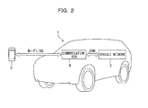
- Fig. 2 is a schematic view of a communication controller and a remote control system for in-vehicle devices according to this embodiment.
- the remote control system includes a vehicle network 2, a multi-functional portable terminal (smartphone) 3, and a communication electronic control unit 4 (communication controller, also referred to as "communication ECU 4").
- the vehicle network 2 is installed in a vehicle 1 and includes various controllers (in-vehicle-device controllers) that control in-vehicle devices.
- the smartphone 3 or a mobile communication device remotely controls the in-vehicle devices.
- the communication ECU 4 is installed in the vehicle 1 and intervenes between the controllers of the vehicle network 2 and the smartphone 3.
- the communication ECU 4 is also referred to as a wireless communication device or an EV remote ECU that functions as a wireless router for controlling wireless communication with the smartphone 3.
- a control area network (CAN) is widely used as the vehicle network 2 because of its high tolerance to noise and the independence of communication lines that allows communication via the remaining lines even after a disconnection of one of the lines.
- a CAN also connects the in-vehicle communication ECU 4 and the vehicle network 2.
- the communication between the communication ECU 4 and the vehicle network 2 is established via a wire CAN, while the communication between the communication ECU 4 and the smartphone 3 is established via various wireless communication networks, such as a wireless fidelity (Wi-Fi) (trademark) scheme, a Third Generation (3G) scheme, a personal area network (PAN), and a radio frequency (RF) identification network.
- Wi-Fi wireless fidelity
- 3G Third Generation
- PAN personal area network
- RF radio frequency
- the Wi-Fi scheme is used for the communication between the communication ECU 4 and the smartphone 3 because the Wi-Fi scheme is supported by many commercially available smartphones and other mobile communication devices, has a relatively high communication rate, has a relatively large wireless communication distance (maximum sight distance for communication with the vehicle is approximately 200 m), and has a low running cost due to its high versatility that does not require a communication infrastructure.
- a mobile communication device using the Wi-Fi scheme is exemplified by a smartphone.
- any other mobile communication device Wi-Fi devices
- Wi-Fi devices including portable game devices and notebook computers, can support the Wi-Fi communication and download application programs (hereinafter, also referred to as application software) for the remote control system.
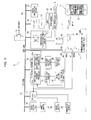
- Fig. 3 illustrates the detailed configuration of the remote control system.
- the vehicle 1 is equipped with in-vehicle devices, such as a main-battery charger 6A that charges a main battery (a battery for running) 5A, an auxiliary-battery charger 6B that charges an auxiliary battery 5B, an air-conditioner (A/C) 12, an audio/navigation system 13, various electric components including a rear defogger 14, lamps 15, door mirrors 16, and wind-shield wipers (not shown), a power switch 17, and door open/close switches 18.
- a main-battery charger 6A that charges a main battery (a battery for running) 5A
- auxiliary-battery charger 6B that charges an auxiliary battery 5B
- A/C air-conditioner
- audio/navigation system 13 various electric components including a rear defogger 14, lamps 15, door mirrors 16, and wind-shield wipers (not shown), a power switch 17, and door open/close switches 18.
- the vehicle 1 is also equipped with in-vehicle-device controllers that control the in-vehicle devices, such as a vehicle ECU (drive controller) 21, an in-vehicle charge ECU (charger) 22, an air-conditioning ECU 23, a comprehensive electrical-equipment control ECU 24, and a power switch ECU 25.
- the vehicle ECU 21 controls the drive of the vehicle 1.
- the in-vehicle charge ECU 22 controls the charge of the main battery 5A and the auxiliary battery 5B.
- the air-conditioning ECU 23 or air-conditioning controller controls the air-conditioner 12.
- the comprehensive electrical-equipment control ECU 24 controls the operation of the electric components, such as the rear defogger 14 and the lamps 15.
- the power switch ECU 25 controls the power switch 17.
- These in-vehicle controllers use the auxiliary battery 5B as power source and run on the auxiliary battery 5B.
- the in-vehicle-device controllers or ECUs 21 to 25, the smartphone 3, and the communication ECU 4 each include an input/output device, a storage device (memory such as an ROM, an RAM, and/or non-volatile RAM), a central processing unit (CPU), and a timer/counter.
- a storage device memory such as an ROM, an RAM, and/or non-volatile RAM
- CPU central processing unit
- timer/counter timer/counter
- the vehicle ECU 21, the in-vehicle charge ECU 22, and the power switch ECU 25 are connected via an electric vehicle CAN (EV-CAN) 51, while the air-conditioning ECU 23, the comprehensive electrical-equipment control ECU 24, and the audio/navigation system 13 are connected via an electrical-equipment CAN (SUB-CAN) 52.
- EV-CAN 51 and the SUB-CAN 52 are sub-networks separated in accordance with features, such as the communication quality, the communication reliability, and the communication rate, and are connected via a communication means, such as a gateway, a bridge, or a repeater (not shown), allowing communication between the EV-CAN 51 and the SUB-CAN 52.
- the vehicle ECU 21 is connected to a brake switch 19 and a temperature sensor 20.
- the power switch ECU 25 includes an operation unit or power switch controller (not shown) that turns on/off the power switch 17 by operating the driving mechanism (power-switch driving mechanism) of the power switch 17 in response to remote control by the smartphone 3.
- the power switch 17 is a push switch installed near the driver' s seat and is operated by the driver and the power switch controller.
- the door open/close switches 18 are sensors that detect the open/close states of the doors of the vehicle 1.
- the brake switch 19 is a sensor that detects the depression of the brake pedal by the driver.
- the temperature sensor 20 detects the ambient temperature AT of the exterior of the vehicle 1.
- the vehicle ECU 21 receives information on the on/off state of the brake switch 19 (depression of brake) and the temperature detected by the temperature sensor 20.
- the power switch ECU 25 receives information on the on/off state of the power switch 17.
- the comprehensive electric-equipment control ECU 24 receives information on the on/off states (open/close states) of the door open/close switches 18 for the doors. Such information is transmitted to other ECUs, such as the vehicle ECU 21, via the EV-CAN 51 and the SUB-CAN 52.
- the power switch 17 has four operating modes: accessories position (ACC), ignition on (IG_ON), READY ON, and READY OFF.
- the ACC mode only the audio/navigation system 13 is activated (turned on) whereas the air-conditioner 12 and the high-voltage devices (in-vehicle devices that run on the high-voltage sources, such as the main-battery charger 6A and the auxiliary-battery charger 6B) are deactivated (turned off). That is, in the ACC mode, the batteries of the vehicle 1 can not be charged and the vehicle 1 cannot travel.
- the power switch ECU 25 selects the ACC mode in response to the power switch 17 being pushed once.
- the audio/navigation system 13 and the air-conditioner 12 are activated, whereas the high-voltage devices are deactivated. That is, in the IG_ON mode, as in the ACC mode, the batteries of the vehicle 1 can not be charged and the vehicle 1cannot travel.
- the power switch ECU 25 selects the IG_ON mode in response to the power switch 17 being pushed twice and sends this information to the air-conditioning ECU 23.
- the vehicle 1 In the READY ON mode, all in-vehicle devices including the high-voltage devices are activated. In this mode, the vehicle 1 can travel, and the main battery 5A and the auxiliary battery 5B can be charged.
- the vehicle ECU 21 selects the READY ON mode upon reception of the information from the power switch ECU 25 on the power switch 17 being pushed and held during reception of the information from the brake switch 19 on the depression of the brake pedal.
- the vehicle ECU 21 and the driving system are disconnected (in this state, the vehicle ECU 21 is turned off).
- the vehicle 1 cannot travel, but the air-conditioner 12 and the main-battery charger 6A can be activated in response to commands associated to timer-scheduled air-conditioning and timer-scheduled charge, which are described below.
- the power switch ECU 25 selects the READY OFF mode in response to the power switch 17 being pushed three times.
- the on/off state of the brake switch 19 (depression of brake) sent to the vehicle ECU 21, the temperature detected by the temperature sensor 20, and the on/off state of the power switch 17 sent to the power switch ECU 25 are input to the communication ECU 4 via the EV-CAN 51 and the SUB-CAN 52.
- the in-vehicle charge ECU 22 includes functions of a main-battery charge controller 22a that controls the charge of the main battery 5A and an auxiliary-battery charge controller 22b that controls the charge of the auxiliary battery 5B.
- the main-battery charge controller 22a controls the main-battery charger 6A to supply the main battery 5A with electric power from an external power source, so that the main battery 5A is charged.
- the main-battery charger 6A can charge the main battery 5A via a dedicated charge socket installed in a charge station or a general power source, such as a household wall socket.
- Three charge modes for the main battery 5A under the control of the main-battery charge controller 22a are provided: "rapid charge” from a dedicated external rapid charger; "200-V normal charge” from a dedicated 200-V external charger; and "100-V normal charge” from a 100-V general power source, such as a household wall socket.
- the main-battery charge controller 22a controls the charge at real-time, for example, through charge via a charge cable connecting the household wall socket and the vehicle 1.
- the main-battery charge controller 22a includes the charge control at real-time and a main-battery-charge timer controller 22a2, sets a timer 22a1 in advance in accordance with a charge schedule, and automatically charges the main battery 5A in accordance with the charge schedule.
- a charge schedule is set with the timer 22a1 in advance for late-night charge (11:00 pm or after), and the charge cable remains connected.
- the main-battery-charge timer controller 22a2 automatically charges the main battery 5A in accordance with the charge schedule (11:00 pm or after). Such a function allows automatic charge during the night at which electricity is supplied at low-cost.
- the auxiliary-battery charge controller 22b controls the auxiliary-battery charger 6B to supply the auxiliary battery 5B with electric power from the main battery 5A, so that the auxiliary battery 5B is charged.
- the auxiliary-battery charger 6B includes a DC-DC converter that lowers the high voltage charged in the main battery 5A to charge the auxiliary battery 5B.
- the auxiliary-battery charge controller 22b includes an auxiliary-battery-charge timer controller 22b2 that sets a timer 22b1 in advance in accordance with a charge schedule, and automatically charges the auxiliary battery 5B in accordance with the charge schedule.
- the charge schedule of the auxiliary battery 5B may be set by an operator through a smartphone to set the timer 22b1 or the timer 22b1 may be set to a fixed value in advance without setting by the operator.
- Timer-scheduled charge starts at a time set in advance and continues for a predetermined charge time T ch .
- the charge time T ch is the time required to charge the electrical power consumed per day in the auxiliary battery 5B and is set to, for example, 10 minutes in advance.
- the auxiliary-battery charge controller 22b further includes a determiner 22b3 and a charge stopper 22b4.
- the determiner 22b3 determines whether timer-scheduled charge is available. Time-controller charge is not available during maintenance of the vehicle 1. Timer-scheduled charge refers to automatic charge of the auxiliary battery 5B from the main battery 5A. Unlike normal charge via a charge gun, timer-scheduled charge cannot be recognized from the exterior of the vehicle 1. Thus, timer-scheduled charge triggered by sudden activation of the high-voltage devices during maintenance of the vehicle 1 may cause unexpected incidents.
- the determiner 22b3 determines whether or not there is a possibility that maintenance of the vehicle 1 is being carried out. This determination, for example, is based on information from the door open/close switches 18 on the doors and/or information from a height sensor (not shown). That is, the determiner 22b3 determines that timer-scheduled charge is not available due to maintenance of the vehicle 1 if at least one door of the vehicle 1 is open and/or the vehicle 1 is lifted. The result by the determiner 22b3 is sent to the charge stopper 22b4.
- the charge stopper 22b4 cancels the timer-scheduled charge by the auxiliary-battery-charge timer controller 22b2 and disables the control or activation of the auxiliary-battery charger 6B. In other words, the charge stopper 22b4 stops the timer-scheduled charge from the main battery 5A to the auxiliary battery 5B in accordance with the result of the determiner 22b3.
- the auxiliary-battery-charge timer controller 22b2 controls the auxiliary-battery charger 6B every day at 2:00 pm to start the charge of the auxiliary battery 5B.
- the timer-scheduled charge is canceled for the day.
- the auxiliary-battery charger 6B charges the auxiliary battery 5B through timer-scheduled charge by the auxiliary-battery-charge timer controller 22b2 and automatic charge by supplying electric power from the main battery 5A to the auxiliary battery 5B.
- Such automatic charge is automatically stopped after a predetermined operating time (for example, 10 minutes) because the auxiliary battery 5B is assumed to be charged to a sufficient level.
- the auxiliary battery 5B can be charged from the main battery 5A or can be charged from an external source in a manner similar to the main battery 5A.
- the air-conditioning ECU 23 controls the air-conditioner 12 on the basis of the information from the vehicle ECU 21 and communication ECU 4.
- the air-conditioner 12 carries out the air-conditioning (cooling/heating) of the interior of the vehicle 1 and blasts air onto the front windshield.
- the air-conditioning schedule is set by a timer in advance, and air-conditioning of the interior of the vehicle 1 and air blast onto the front windshield are carried out in accordance with the air-conditioning schedule.
- the air-conditioning ECU 23 controls the air-conditioning at real time and the timer-scheduled air-conditioning.
- the timer-scheduled air-conditioning is referred to as "preliminary air-conditioning" and carried out if the interior of the vehicle 1 should be air-conditioned before a passenger or passengers enter the vehicle 1. If a driver is to ride the vehicle 1 for commuting to work every day around the same time, the timer can be set to activate the air-conditioner 12 shortly before the expected time of entering the vehicle 1. The timer can set the day and time for activating the air-conditioning.
- the air-conditioning modes of the air-conditioner 12 include “air-conditioning (cooling) standby,” “air-conditioning (cooling),” “air-conditioning (heating) standby,” “air-conditioning (heating),” “air-conditioning(front windshield blast) standby,” and “air-conditioning (front windshield blast)” modes.
- air-conditioning standby mode In each air-conditioning standby mode, the air-conditioning is scheduled but is not yet activated.
- the comprehensive electric-equipment control ECU 24 controls the operation of the electric components, such as the rear defogger 14, the lamps 15 including the head lights and position lamps, the door mirrors 16, and the windshield wipers, and detects the operating state of these electric components.
- the electric components such as the rear defogger 14, the lamps 15 including the head lights and position lamps, the door mirrors 16, and the windshield wipers.
- the communication ECU 4 includes a transmission/reception antenna 41, an IG terminal 42, a +B terminal 43, a ground terminal 44, and a CAN connection terminal 45.
- the IG terminal 42 is connected to an ignition power source while the power switch 17 is being at the IG_ON position.
- the +B terminal 43 is in constant connection with the battery power source.
- the ground terminal 44 is grounded.
- the CAN connection terminal 45 is connected to the SUB-CAN 52.
- the communication ECU 4 also includes a charge-standby-signal output unit 46 and a system-start-signal output unit 47.
- the charge-standby-signal output unit 46 outputs a signal WUCI for temporarily holding the charge functions.
- the system-start-signal output unit 47 outputs a WakeUp signal WUCO for starting the system of the electric vehicle.
- the communication ECU 4 includes a communication unit 4a, as illustrated in Fig. 1 .
- the communication unit 4a receives information on the remote control by the smartphone 3, sends this information to the vehicle ECU 21 and the in-vehicle charge ECU 22, and also sends information including the charge state of the main battery 5A and the control state of the vehicle ECU 21 to the smartphone 3 so as to carry out wireless communication control.
- the smartphone 3 downloads application software for the remote control system and launches this application software to display various images on the touch panel display 30 of the smartphone 3. Descriptions are omitted on the images displayed on the touch panel display 30.
- the communication ECU 4 uses the auxiliary battery 5B as power source and runs on the auxiliary battery 5B.
- the communication ECU 4 is constantly in a communication stand-by mode and can receive signals from the smartphone 3, regardless of the operating state of the main battery 5A.
- the auxiliary battery 5B constantly supplies the stand-by current to the communication ECU 4.
- wireless communication for example, by a Wi-Fi scheme, requires a large stand-by current of the communication ECU 4, which often causes a reduction in the charge capacity of the auxiliary battery 5B.
- the power consumption per day (24 hours) of the communication ECU 4 in stand-by mode is estimated in advance, and the power of the auxiliary battery 5B consumed per day by the communication ECU 4 is charged during operation of the high-voltage devices (i.e., in the READY ON mode) or by timer-scheduled charge. In this way, the auxiliary battery 5B is prevented from running out.
- timer-scheduled charge by the auxiliary battery 5B is stopped by the charge stopper 22b4, as described above, timer-scheduled charge is not carried out that day. Further at this time, if the high-voltage devices are not activated (for example, if the vehicle 1 does not enter the READY ON mode), the auxiliary battery 5B is not charged. If the communication ECU 4 is constantly in a communication stand-by state in such a case, the communication ECU 4 continuously consumes the power of the auxiliary battery 5B, causing the auxiliary battery 5B to run out by insufficiency of electric power. Alternatively, even if timer-scheduled charge of the auxiliary battery 5B is carried out, when the temperature of the auxiliary battery 5B is low, causing low charge acceptance, the auxiliary battery 5B cannot be charged to a desired level and may run out.
- the communication ECU 4 limits the communication to prevent the auxiliary battery 5B from running out.
- the communication ECU 4 functions as a stopper 4b, a recovery unit 4c, and a corrector 4d to limit the communication, as illustrated in Fig. 1 .
- the stopper 4b turns off the communication stand-by mode of the communication unit 4a (in other words, stops the wireless communication between the smartphone 3 and the communication ECU 4), if one of the three conditions described below is met.
- the first condition consists of: no entrance of the READY ON mode until a first predetermined time T1 elapses from the start of the READY OFF mode, and no timer-scheduled charge.
- the timer-scheduled charge is normally carried out every day at a predetermined time in accordance with the charge schedule, but may be stopped by the charge stopper 22b4, as described above. In such a case, if the vehicle 1 does not enter the READY ON mode, the charge capacity of the auxiliary battery 5B remains low because power is not charged. Thus, the stopper 4b turns off the communication stand-by mode of the communication ECU 4.
- the first predetermined time T1 is longer than 24 hours and, for example, is set to 36 hours depending on the capacity of the auxiliary battery 5B.
- the second condition consists of: no entrance of the READY ON mode until a first predetermined time T1 elapses from the start of the READY OFF mode, and the ambient temperature AT acquired at the first predetermined time T1 being equal to or lower than a predetermined temperature AT 0 .
- the first predetermined time T1 is the same as that in the first condition.
- the ambient temperature AT is acquired by the temperature sensor 20 as a temperature correlating with the temperature of the auxiliary battery 5B. In other words, a temperature that affects the charge acceptance of the auxiliary battery 5B can be readily detected by detecting the ambient temperature AT instead of directly detecting the temperature of the auxiliary battery 5B.
- the predetermined temperature AT 0 is a temperature at which the charge acceptance of the auxiliary battery 5B decreases and the auxiliary battery 5B is not charged to a desired level (which is equal to the power consumed by the auxiliary battery 5B in one day) even when timer-scheduled charge is carried out for a predetermined charge time T CH .
- the predetermined temperature AT 0 is set, for example, to -15°C.
- the stopper 4b determines that the auxiliary battery 5B is insufficiently charged in spite of the timer-scheduled charge and turns off the communication stand-by mode of the communication ECU 4.
- the wireless communication with the smartphone 3 by the communication unit 4a is disconnected, preventing a decrease in the remaining charge level of the auxiliary battery 5B due to the communication ECU 4 in the communication stand-by mode.
- the timing of acquisition of the ambient temperature AT is not limited to that described above and may be any other time until the first predetermined time T1 elapses from the start of the READY OFF mode, which is, for example, before or after the time for timer-scheduled charge or during the night at which the ambient temperature AT is low.
- the correlating temperature is not limited to the ambient temperature AT and may be the peripheral temperature of the auxiliary battery 5B or the temperature of the main battery 5A. Alternatively, the correlating temperature may be the directly detected temperature of the auxiliary battery 5B.
- the third condition consists of: the ambient temperature AT being equal to or lower than the predetermined temperature AT 0 before the start of the READY ON mode, even if the second condition is not satisfied. That is, if the ambient temperature AT is higher than the predetermined temperature AT 0 when the first predetermined time T1 elapses from the start of the READY OFF mode, the second condition is not satisfied, and thus, the communication unit 4a remains in the communication stand-by mode. If the READY ON mode is not turned on eventually, the power consumption of the auxiliary battery 5B continues to increase.
- the ambient temperature AT is slightly higher than the predetermined temperature AT 0 (for example, -12°C) and the charge acceptance of the auxiliary battery 5B is lower than that at normal temperatures, it is likely that the auxiliary battery 5B is not charged to a desired level through the timer-scheduled charge.
- the predetermined temperature AT 0 for example, -12°C
- the stopper 4b turns off the communication stand-by mode of the communication ECU 4 at this time.
- This operation stops the wireless communication with the smartphone 3, and prevents the remaining charge level of the auxiliary battery 5B from decreasing due to the communication stand-by mode of the communication ECU 4.
- the stopper 4b compares the ambient temperature AT with the predetermined temperature AT 0 at the first predetermined time T1 after the start of the READY OFF mode, and continues to periodically compare the ambient temperature AT with the predetermined temperature AT 0 every given time T S .
- Such comparison can eliminate the constant monitoring of the variation in the ambient temperature AT, and thus can reduce the load for control.
- the ambient temperature AT varies greatly between day and night.
- the variation in the ambient temperature AT can be appropriately monitored while reducing the load for control.
- the recovery unit 4c recovers the communication stand-by mode of the communication ECU 4 if a predetermined recovery condition is satisfied while the communication stand-by mode of the communication ECU 4 is being turned off by the stopper 4b. In other words, the recovery unit 4c recovers the wireless communication by the communication unit 4a if the recovery condition is satisfied after the wireless communication with the smartphone 3 is stopped by the stopper 4b.
- the recovery condition consists of the continuation of the READY ON mode for at least a second predetermined time T2.
- the second predetermined time T2 is a minimum time for supplementing (charging) the electric power consumed in the auxiliary battery 5B when the communication ECU 4 remains in the communication stand-by mode all day long, and is set, for example, to 10 minutes.
- the second predetermined time T2 is set to the minimum time to prevent a decrease in the cruising distance, which is caused by excess charge of the auxiliary battery 5B from the main battery 5A.
- the recovery unit 4c determines that the charge of the auxiliary battery 5B reaches to a level sufficient for recovery of the wireless communication with the smartphone 3, and turns on the communication stand-by mode of the communication ECU 4.
- the recovery condition prevents the recovery of the wireless communication in the case where the READY ON mode is turned on for an instant.
- the auxiliary battery 5B is certainly prevented from running out.
- the corrector 4d corrects the second predetermined time T2, which is used by the recovery unit 4c to determine the satisfaction of the recovery condition.
- the corrector 4d corrects the second predetermined time T2 in accordance with the ambient temperature AT detected by the temperature sensor 20.
- the auxiliary battery 5B is characterized in that the charge acceptance starts to decrease if the ambient temperature AT falls below a threshold temperature AT 1 .
- the threshold temperature AT 1 ranges from about -8°C to 10°C, depending on the characteristics of the adopted batteries and the adopted vehicle system.
- the threshold temperature AT 1 is higher than the predetermined temperature AT 0 mentioned above. In other words, the predetermined temperature AT 0 is set lower than the threshold temperature AT 1 .
- the corrector 4d may correct the second predetermined time T2 on the basis of the state of charge SOC of the auxiliary battery 5B, instead of the ambient temperature AT.
- information such as the voltage and/or current of the auxiliary battery 5B may be acquired to estimate the state of charge SOC of the auxiliary battery 5B.
- the estimation may include procedures of adding the power charged to the auxiliary battery 5B to the initial level of the auxiliary battery 5B while subtracting the power discharged from the initial level of the auxiliary battery 5B to track the power charged to and discharged from the auxiliary battery 5B.
- the corrector 4d grasps the actual state of charge SOC of the auxiliary battery 5B and corrects the second predetermined time T2 to make it longer if the recovery condition is satisfied such that the auxiliary battery 5B is charged in the READY ON mode for the second predetermined time T2 but the charge of the auxiliary battery 5B is insufficient for the supplement of the power consumed in one day (i.e., the charge level of the auxiliary battery 5B runs short).
- the corrector 4d may correct the second predetermined time T2 on the basis of the ambient temperature AT and the state of charge SOC of the auxiliary battery 5B.
- the corrector 4d may not be provided, and the second predetermined time T2 may be set to a fixed value (for example, 10 minutes). This reduces the load for control.
- the second predetermined time T2 is not corrected by the corrector 4d. That is, the second predetermined time T2, which is used for determination of the satisfaction of the recovery condition, is set to a fixed value.
- the process illustrated in the flow chart is repeated in predetermined cycles in the inside of the communication ECU 4.
- Step S10 determines whether the communication ECU 4 is in the communication stand-by mode. If the communication unit 4a turns on the communication stand-by mode (communication on), the process goes to Step S20 to determine the satisfaction of the stop condition of the wireless communication. Alternatively, if the communication unit 4a does not turn on the communication stand-by mode (i.e., if the communication unit 4a turns off the wireless communication), the process goes to Step S130 to determine the satisfaction of the recovery condition of the wireless communication.
- Step S20 determines whether the READY OFF mode is on. If the READY OFF mode is on, the process goes to Step S30, whereas if the READY ON mode is on, the control cycle ends. Step S30 determines whether the READY OFF mode has continued for at least the first predetermined time T1. If the READY OFF mode has continued for at least the first predetermined time T1, the process goes to Step S40; else, the control cycle ends.
- Step S40 determines whether the timer-scheduled charge by the auxiliary-battery-charge timer controller 22b2 has been carried out during the first predetermined time T1. Step S40 also determines whether the preliminary air-conditioning and the charge of the main battery 5A have been carried out during the first predetermined time T1 and the DC-DC converter has been activated for 10 minutes. If the determination at Step S40 is YES, the process goes to Step S50 to determine whether a flag F equals zero. If the determination at Step S40 is NO, the first condition described above is satisfied, and the process goes to Step S110 to turn off the communication stand-by mode by the stopper 4b (to stop the wireless communication between the smartphone 3 and the communication ECU 4). Then, Step S120 resets the flag F to zero, and the control cycle ends.
- the flag F is a variable for determining whether the ambient temperature AT is higher than the predetermined temperature AT 0 (AT> AT 0 ) (i.e., a variable for determining whether the ambient temperature AT is to be redetected) as a result of comparing the ambient temperature AT and the predetermined temperature AT 0 .
- the flag F equals one if AT> AT 0 (i.e., redetection of the ambient temperature AT is not required), whereas the flag F equals zero for any other result of the comparison.
- Step S50 goes to Step S60 to detect the ambient temperature AT by the temperature sensor 20.
- Step S90 determines whether the given time T S has elapsed from the moment of setting the flag F to one (i.e., the moment of the comparison of the ambient temperature AT and the predetermined temperature AT 0 ). If the given time T S has not elapsed, the control cycle ends. If the READY OFF mode continues for the time T S , the process goes from Step S50 to Step S90 in the subsequent control cycles to repeat Step S90.
- the predetermined time T1 of the determination condition of Step S40 is counted from the start of the READY OFF mode in the first control cycle (i.e., equal to the first predetermined time T1 in Step S30). After timer-scheduled charge is carried out, the first predetermined time T1 is counted from the previous timer-scheduled charge time. That is, the predetermined time T1 in Step S30 may differ from the predetermined time T1 in Step S40.
- Step S90 determines that the given time T S has elapsed, the process goes to Step S100 to reset the flag F to zero, and the control cycle ends.
- Step S60 again to detect the ambient temperature AT and then the determination in Step S70 is carried out.
- AT ⁇ AT 0 the third condition described above is satisfied, and the process goes to Step S110 to turn off the communication stand-by mode by the stopper 4b (the wireless communication between the smartphone 3 and the communication ECU 4 is stopped).
- Step S120 resets the flag F to zero, and the control cycle ends. The satisfaction of the stop condition is determined in this way.
- Step S10 determines that the communication stand-by mode is not turned on, the wireless communication between the smartphone 3 and the communication ECU 4 is being stopped. Thus, the process goes to Step S130 to determine whether the READY ON mode is turned on. If the READY ON mode is not turned on, the control cycle ends, and the wireless communication is not recovered. Alternatively, if the READY ON mode is turned on, it is determined whether the READY ON mode has continued for at least the second predetermined time T2. That is, it is determined whether the auxiliary battery 5B has been charged for the power consumed by the stand-by current of the communication ECU 4.
- Step S150 the process goes to Step S150 to recover the communication stand-by mode of the communication ECU 4 by the recovery unit 4c (the wireless communication is restored between the smartphone 3 and the communication ECU 4) .
- Step S160 resets the flag F to zero, and the control cycle ends.
- the control cycle ends. That is, the wireless communication is recovered only if the READY ON mode has continued for at least the second predetermined time T2.
- Figs. 5 and 6 are time charts illustrating the on/off states of the communication stand-by mode, the READY ON and READY OFF modes, and the timer-scheduled charge of the communication ECU 4 over time.
- the timer-scheduled charge illustrated in Figs. 5 and 6 is normally carried out at 2:00 pm every day.
- the switching from the READY ON mode to the READY OFF mode at 10:00 pm on Sunday immediately starts the counting of the timer in the communication ECU 4. Even if the READY OFF mode is turned on, the communication stand-by mode remains being on by the communication unit 4a. If the READY ON mode is never turned on until the first predetermined time T1 (36 hours) elapses from the start of the READY OFF mode, the ambient temperature AT is acquired when the first predetermined time T1 elapses (at 10:00 am on Tuesday). The acquired ambient temperature AT is compared with the predetermined temperature AT 0 .
- Fig. 5 illustrates a case where AT ⁇ AT 0 holds at 10:00 am on Tuesday.
- the ambient temperature AT acquired when the first predetermined time T1 elapses (at 10:00 am on Tuesday) after the start of the READY OFF mode (10:00 pm on Sunday) is equal to the predetermined temperature AT 0 or less.
- the stopper 4b turns off the communication stand-by mode of the communication ECU 4 at 10:00 am on Tuesday.
- Fig. 6 illustrates a case where AT ⁇ AT 0 does not hold at 10:00 am on Tuesday.
- the ambient temperature AT acquired when the first predetermined time T1 elapses (at 10:00 am on Tuesday) after the start of the READY OFF mode (10:00 pm on Sunday) is higher than the predetermined temperature AT 0 .
- the wireless communication with the smartphone 3 is not stopped at the time.
- the READY OFF mode continues, the ambient temperature AT is acquired again at 4:00 pm on Tuesday when the given time T S (six hours) elapses after the time of the comparison of the ambient temperature AT and the predetermined temperature AT 0 (10:00 am on Tuesday). That is, the ambient temperature AT is compared with the predetermined temperature AT 0 again at 4:00 pm on Tuesday.
- the communication stand-by mode turned off is turned on (the wireless communication is recovered) after the READY ON mode continues for at least the second predetermined time T2 from the switching of the READY OFF mode to the READY ON mode, as illustrated in Figs. 5 and 6 .
- the vehicle 1 provided with the communication ECU 4 stops the wireless communication with the smartphone 3 when the correlating temperature AT is equal to the predetermined temperature AT 0 or less, the correlating temperature AT correlating with the temperature of the auxiliary battery 5B, which is acquired within the first predetermined time T1 from the stop of the vehicle ECU 21 (i.e., the start of the READY OFF mode).
- This prevents insufficiency of electric power of the auxiliary battery 5B which is the power source of the communication ECU 4, and thereby prevents the auxiliary battery 5B from running out.
- a low correlating temperature AT causes a decrease in the charge acceptance of the auxiliary battery 5B.
- a desired charge level is less likely to be achieved through normal timer-scheduled charge. If the wireless communication stand-by mode remains being on in this state, the electric power of the auxiliary battery 5B decreases, and the auxiliary battery 5B will eventually run out. If the auxiliary battery 5B runs out, the vehicle 1 cannot be driven even with the normal operation of the other in-vehicle devices and the main battery 5A. Such a trouble, however, does not occur in the present invention.
- the acquisition of the ambient temperature AT as a correlating temperature allows the ready acquisition of a temperature correlating to the temperature of the auxiliary battery 5B by the temperature sensor 20. Since the ambient temperature AT is used as a correlating temperature, a dedicated temperature sensor is not required for the auxiliary battery 5B, and thus, costs can be reduced.
- the stopper 4b acquires the ambient temperature AT when the first predetermined time T1 elapses after the start of the READY OFF mode (at the stop of the vehicle ECU 21) and compares the acquired ambient temperature AT with the predetermined temperature AT 0 . This allows the determination of the temperature and the stop control of the wireless communication to be carried out simultaneously, and thus, can reduce the load for control.
- the stopper 4b acquires the ambient temperature AT every given time T S from the first predetermined time T1 until the READY ON mode is turned on again and stops the wireless communication by the communication unit 4a when an ambient temperature AT equals to the predetermined temperature AT 0 or less. In this way, the auxiliary battery 5B can be certainly prevented from running out.
- Such acquisition of the ambient temperature AT at every given time T S eliminates the constant monitoring of the variation in the ambient temperature AT, and thus reduces the load for control.
- the recovery of the wireless communication with the smartphone 3 after the READY ON mode (i.e., the operation of the vehicle ECU 21) continues for at least the second predetermined time T2 prevents the auxiliary battery 5B from running out. That is, not recovering the wireless communication in response to the READY ON mode being turned on for an instant, and establishing a recovery condition consisting of the continuation of the READY ON mode for at least the second predetermined time T2 maintains the state of charge SOC of the auxiliary battery 5B.
- the second predetermined time T2 is set to a minimum time for the charge of the electric power consumed in the auxiliary battery 5B after the communication ECU 4 remains in the communication stand-by mode all day long. Such setting can prevent a decrease in the cruising distance caused by excess charge of the auxiliary battery 5B from the main battery 5A.
- the elimination of the correction of the second predetermined time T2 leads to a decrease in the load of calculation and the elimination of a means for estimating or detecting the state of charge SOC of the auxiliary battery 5B.
- the corrector 4d for correcting the second predetermined time T2 optimizes the recovery condition for recovering the wireless communication.
- the correction of the second predetermined time T2 by the corrector 4d in accordance with the ambient temperature AT maintains an appropriate charge level of the auxiliary battery 5B with consideration of the effect of the temperature.
- An ambient temperature AT lower than the threshold temperature AT 1 causes a decrease in the charge acceptance of the auxiliary battery 5B.
- the second predetermined time T2 is corrected so as to be longer as the ambient temperature AT decreases, and thereby the charge level of the auxiliary battery 5B is appropriately maintained.
- the correction of the second predetermined time T2 by the corrector 4d in accordance with the state of charge SOC of the auxiliary battery 5B involves the grasp of the actual state of charge SOC of the auxiliary battery 5B, and thus, can achieve more appropriate maintenance of the charge level of the auxiliary battery 5B.
- the first predetermined time T1, the second predetermined time T2, the given time T S , and the charge time T CH which are mentioned above, are merely examples and are not limited to the times mentioned above.
- the first predetermined time T1 and the given time T S may be set to be shorter than the times mentioned above to decrease the intervals between the comparisons of the ambient temperature AT with the predetermined temperature AT 0 .
- the second predetermined time T2 and charge time T CH may be set to be longer than the times mentioned above to maintain a high state of charge of the auxiliary battery 5B.
- the recovery condition is not limited to "the continuation of the READY ON mode for at least the second predetermined time T2," as described above.
- a temporary recovery condition may consist of "the READY ON mode being on for at least one instant”
- a cancelation condition for the temporary recovery may consist of "the READY ON mode not continuing for the second predetermined time T2 after the recovery of the wireless communication.”
- the satisfaction of the temporary recovery condition recovers the wireless communication with the smartphone 3, and the satisfaction of the cancelation condition for temporary recovery stops the wireless communication again. This can prevent the auxiliary battery 5B from running out.
- a Wi-Fi communication scheme is used.
- the communication standard is not limited to this.
- the embodiments can be applied to mobile communication devices that can automatically connect to a receiver of a wireless LAN nearby.
- the preferred communication standard such as the Wi-Fi communication scheme, has a high communication rate, has a relatively large wireless communication distance, has high versatility, eliminates upgrading of the infrastructure, and reduces running costs.
- the present invention is effective for vehicles provided with in-vehicle devices that can be remotely controlled with a mobile communication device.
- the present invention can be effectively applied to mobile communication devices that can automatically connect to a receiver of a wireless LAN nearby.
Landscapes
- Engineering & Computer Science (AREA)
- Power Engineering (AREA)
- Transportation (AREA)
- Mechanical Engineering (AREA)
- Life Sciences & Earth Sciences (AREA)
- Sustainable Development (AREA)
- Sustainable Energy (AREA)
- Electric Propulsion And Braking For Vehicles (AREA)
- Secondary Cells (AREA)
Abstract
Description
- The present invention relates to a vehicle provided with in-vehicle devices that can be remotely controlled with a mobile communication device.
- Techniques have been developed and widely used for remote control of devices installed in automobiles (hereinafter, also referred to as "vehicles"). For example, techniques have been developed for starting engines of vehicles by remote control to preliminarily warm-up the engines, and for activating air conditions of vehicles by remote control to control a temperature in the vehicles after starting the engines before passengers enter the vehicles. Such techniques are disclosed in Japanese Laid-open Patent Publication No.
11-230013 -
Patent document 1 describes a technique involving a control circuit for control of an aftermarket electric device installed in a vehicle. This vehicle has an engine control circuit that is wirelessly controllable to start/stop the engine of the vehicle through operation of a portable controller (remote controller) provided with a start switch and a stop switch. The aftermarket electric device is turned on by an operation-start signal which is an operation signal from the start switch during operation of the engine and turned off by an operation-stop signal which is an operation signal from the stop switch during a halt of the engine. - In addition to the preliminary air-conditioning described above, the inventors have believed that electric vehicles and plug-in hybrid vehicles that are chargeable via household wall sockets can be more convenient with remote detection and control of the start and stop of the electrical charge of the vehicles in a chargeable state in which the charging systems of the vehicles are connected to electric sockets. Such remote control of various devices enhances the convenience of the vehicles in use.
- Dedicated portable controllers provided for the respective devices to be remotely controlled lead to increased costs, management burden, and incorrect operation. Such drawbacks are solved by the technique disclosed in
patent document 1, which enables devices to be remotely controlled by a portable controller. - This technique uses a switch operation logic of a single switch to remotely control multiple devices. Consequently, an increase in the number of devices to be remotely controlled causes an increase in the complexity of the switch operation logic. Such a complicated switch operation logic cannot be readily operated and may lead to incorrect operation. The portable controller may be equipped with switches corresponding to the devices to be remotely controlled. In such a case, however, the switch configuration of the portable controller becomes complicated, and makes operation difficult that incorrect operation would increase.
- The inventors have conceived the use of mobile communication devices, such as mobile phones, for remote control of various devices in a vehicle. The mobile phones popular today are multifunctional mobile phones, which are referred to as "smartphones." Smartphones have functions similar to those of personal computers and personal digital assistants (PDAs), and typically are equipped with touch panel displays. Thus, application software can be downloaded to obtain desired functions, allowing smartphones to remotely control in-vehicle devices.
- That is, the application software can be developed to display a menu and switch buttons on a touch panel display for remote control of devices and to operate the switch buttons. The application software can be downloaded to a smartphone, enabling the smartphone to be used as a remote controller of the devices. The flexibility in the menu display facilitates appropriate operations without incorrect operation.
- Wireless communication between a mobile communication device, such as a smartphone, and a vehicle requires the vehicle to be equipped with a wireless communication device (communication control device) supporting the communication standard (network interface) employed by the mobile communication device. The communication standards of smartphones include Wi-Fi (trademark) and 3G. In addition to these, communication standards, such as WiMAX (trademark) and Bluetooth (trademark) may also be used.
- Among these communication standards, Wi-Fi has a relatively high communication rate, a relatively large wireless communication distance, and a low running cost due to its high versatility that does not require a communication infrastructure. Thus, mobile communication devices that support Wi-Fi can be readily used for remote control of in-vehicle devices. In such a case, a wireless communication device supporting such a standard is installed in the vehicle. Generally, such a wireless communication device in the vehicle is always in a communication standby mode and is ready to receive transmission from a smartphone or any other devices at all times.
- Unfortunately, the wireless communication device in the vehicle that is in a communication standby mode constantly discharges its battery, which is the power source of the wireless communication device, due to a standby current. As a result, the state of charge of the battery rapidly decreases. In other words, upon performing a wireless communication between mobile communication devices that support Wi-Fi and the vehicle, the constant standby mode of the wireless communication device is advantageous as above, whereas this standby state requires a large standby current and causes a rapid decrease the state of charge of the battery. Especially, the state of charge of a battery having a small capacity tends to drop significantly due to the consumption by the standby current. This is a major problem.
- Electric vehicles and plug-in hybrid vehicles have large-capacity high-voltage sources (batteries for running the vehicles). A candidate method of charging the battery as the power source of the wireless communication device is periodic supply of electric power from the high-voltage source. This way, the electric power consumed by the wireless communication device for the stand-by current can be supplemented to constantly maintain the communication stand-by mode of the wireless communication device.
- An important issue for electric vehicles and plug-in hybrid vehicles is an improvement in the cruising distance in motor traveling. Although the batteries are chargeable with high-voltage sources, there is a strong demand for saving the power charged in the high-voltage sources. A scheduled charge of a battery in a low-temperature environment may result in an insufficient charge capacity of the battery because the charge acceptance of the battery is lower than that in a normal-temperature environment. If the wireless communication device is constantly in a communication stand-by mode, the charge capacity of the battery runs short and the battery runs out.
- An object of the present invention, which has been conceived in light of the issues described above, is to provide a vehicle that can prevent insufficient charge of batteries being power sources in a system including in-vehicle devices that are remotely controlled with a mobile communication device, such as a smartphone. Another object of the present invention is to achieve advantages through the configurations according to the embodiments of the present invention described below, the advantages not being achievable through conventional art.
-
- (1) The present invention provides a vehicle equipped with in-vehicle devices remotely controllable with a mobile communication device, the vehicle including a drive controller for controlling drive of the vehicle; a communication controller that controls wireless communication with the mobile communication device; and an auxiliary battery that activates the communication controller and an in-vehicle-device controller that controls the in-vehicle devices. The communication controller includes a stopper that stops the wireless communication if a correlating temperature is lower than or equal to a predetermined temperature, the correlating temperature correlating with the temperature of the auxiliary battery acquired at a first predetermined time after a stop of the drive controller.
- The stop of the drive controller refers to the disconnection of the drive controller from a driving system as a result of the operation by an operator (i.e. modes referred to as IG_OFF and READY OFF). The temperature correlating with the temperature of the auxiliary battery is, for example, an actual temperature of the auxiliary battery, a peripheral temperature of the auxiliary battery, or an ambient temperature.
- (2) Preferably, the stopper acquires an ambient temperature as the correlating temperature. In such a case, preferably a temperature sensor that detects the ambient temperature is installed in the vehicle.
- (3) Preferably, the stopper acquires the correlating temperature at every given time after the first predetermined time until the drive controller is reactivated if the predetermined temperature is lower than the correlating temperature acquired at the first predetermined time after the stop of the drive controller, and stops the wireless communication if the correlating temperature is lower than or equal to the predetermined temperature.
- (4) Preferably, the communication controller includes a recovery unit that recovers the wireless communication if the drive controller continues to operate for a second predetermined time while the wireless communication with the mobile communication device is stopped by the stopper.
- (5) Preferably, the communication controller includes a corrector that corrects the second predetermined time.
- (6) Preferably, the corrector corrects the second predetermined time in accordance with the correlating temperature.
- (7) Preferably, the corrector corrects the second predetermined time in accordance with the state of charge of the auxiliary battery.
- The vehicle according to the present invention stops the wireless communication with the mobile communication device if the correlating temperature is equal to the predetermined temperature or less, the correlating temperature correlating with the temperature of the auxiliary battery acquired at the first predetermined time after the stop of the drive controller. This prevents insufficiency of electric power of the auxiliary battery being power source, and thereby certainly prevents the auxiliary battery from running out.
- The nature of this invention, as well as other objects and advantages thereof, will be explained in the following with reference to the accompanying drawings, in which like reference characters designate the same or similar parts throughout the figures and wherein:
-
Fig. 1 is a block diagram of essential components of a communication controller of a vehicle and a remote control system therewith for in-vehicle devices according to an embodiment. -
Fig. 2 is a schematic view of the communication controller of a vehicle and the remote control system therewith for in-vehicle devices according to an embodiment. -
Fig. 3 is a detailed schematic view of the communication controller of a vehicle and the remote control system therewith for in-vehicle devices according to an embodiment. -
Fig. 4 is an example of a flow chart of the control carried out by the communication controller. -
Fig. 5 is a timing chart of an example content of the control carried out by the communication controller. -
Fig. 6 is a timing chart of another example content of the control carried out by the communication controller. - Embodiments will now be described with reference to the accompanying drawings.
- The embodiments describe, as an example, a plug-in hybrid vehicle (PHV) equipped with a main battery (a battery for running) chargeable via a general power source (100 V source) provided outside the vehicle, such as a household wall socket. Devices installed in the vehicle (in-vehicle devices) include the main battery, which is a high-voltage source, an auxiliary battery that is charged from the main battery, and an auxiliary-battery charger that charges the auxiliary battery.
-
Fig. 2 is a schematic view of a communication controller and a remote control system for in-vehicle devices according to this embodiment. As illustrated inFig. 2 , the remote control system includes avehicle network 2, a multi-functional portable terminal (smartphone) 3, and a communication electronic control unit 4 (communication controller, also referred to as "communication ECU 4"). Thevehicle network 2 is installed in avehicle 1 and includes various controllers (in-vehicle-device controllers) that control in-vehicle devices. Thesmartphone 3 or a mobile communication device remotely controls the in-vehicle devices. Thecommunication ECU 4 is installed in thevehicle 1 and intervenes between the controllers of thevehicle network 2 and thesmartphone 3. Thecommunication ECU 4 is also referred to as a wireless communication device or an EV remote ECU that functions as a wireless router for controlling wireless communication with thesmartphone 3. - A control area network (CAN) is widely used as the
vehicle network 2 because of its high tolerance to noise and the independence of communication lines that allows communication via the remaining lines even after a disconnection of one of the lines. A CAN also connects the in-vehicle communication ECU 4 and thevehicle network 2. - The communication between the
communication ECU 4 and thevehicle network 2 is established via a wire CAN, while the communication between thecommunication ECU 4 and thesmartphone 3 is established via various wireless communication networks, such as a wireless fidelity (Wi-Fi) (trademark) scheme, a Third Generation (3G) scheme, a personal area network (PAN), and a radio frequency (RF) identification network. In this embodiment, the Wi-Fi scheme is used for the communication between thecommunication ECU 4 and thesmartphone 3. - The Wi-Fi scheme is used for the communication between the
communication ECU 4 and thesmartphone 3 because the Wi-Fi scheme is supported by many commercially available smartphones and other mobile communication devices, has a relatively high communication rate, has a relatively large wireless communication distance (maximum sight distance for communication with the vehicle is approximately 200 m), and has a low running cost due to its high versatility that does not require a communication infrastructure. - In this embodiment, a mobile communication device using the Wi-Fi scheme is exemplified by a smartphone. Alternatively, any other mobile communication device (Wi-Fi devices), including portable game devices and notebook computers, can support the Wi-Fi communication and download application programs (hereinafter, also referred to as application software) for the remote control system.
-
Fig. 3 illustrates the detailed configuration of the remote control system. As illustrated inFig. 3 , thevehicle 1 is equipped with in-vehicle devices, such as a main-battery charger 6A that charges a main battery (a battery for running) 5A, an auxiliary-battery charger 6B that charges anauxiliary battery 5B, an air-conditioner (A/C) 12, an audio/navigation system 13, various electric components including arear defogger 14,lamps 15, door mirrors 16, and wind-shield wipers (not shown), apower switch 17, and door open/close switches 18. - The
vehicle 1 is also equipped with in-vehicle-device controllers that control the in-vehicle devices, such as a vehicle ECU (drive controller) 21, an in-vehicle charge ECU (charger) 22, an air-conditioning ECU 23, a comprehensive electrical-equipment control ECU 24, and apower switch ECU 25. Thevehicle ECU 21 controls the drive of thevehicle 1. The in-vehicle charge ECU 22 controls the charge of themain battery 5A and theauxiliary battery 5B. The air-conditioning ECU 23 or air-conditioning controller controls the air-conditioner 12. The comprehensive electrical-equipment control ECU 24 controls the operation of the electric components, such as therear defogger 14 and thelamps 15. Thepower switch ECU 25 controls thepower switch 17. These in-vehicle controllers use theauxiliary battery 5B as power source and run on theauxiliary battery 5B. - The in-vehicle-device controllers or
ECUs 21 to 25, thesmartphone 3, and thecommunication ECU 4 each include an input/output device, a storage device (memory such as an ROM, an RAM, and/or non-volatile RAM), a central processing unit (CPU), and a timer/counter. - The
vehicle ECU 21, the in-vehicle charge ECU 22, and thepower switch ECU 25 are connected via an electric vehicle CAN (EV-CAN) 51, while the air-conditioning ECU 23, the comprehensive electrical-equipment control ECU 24, and the audio/navigation system 13 are connected via an electrical-equipment CAN (SUB-CAN) 52. The EV-CAN 51 and the SUB-CAN 52 are sub-networks separated in accordance with features, such as the communication quality, the communication reliability, and the communication rate, and are connected via a communication means, such as a gateway, a bridge, or a repeater (not shown), allowing communication between the EV-CAN 51 and the SUB-CAN 52. - The
vehicle ECU 21 is connected to abrake switch 19 and atemperature sensor 20. Thepower switch ECU 25 includes an operation unit or power switch controller (not shown) that turns on/off thepower switch 17 by operating the driving mechanism (power-switch driving mechanism) of thepower switch 17 in response to remote control by thesmartphone 3. - The
power switch 17 is a push switch installed near the driver' s seat and is operated by the driver and the power switch controller. The door open/close switches 18 are sensors that detect the open/close states of the doors of thevehicle 1. Thebrake switch 19 is a sensor that detects the depression of the brake pedal by the driver. Thetemperature sensor 20 detects the ambient temperature AT of the exterior of thevehicle 1. - The
vehicle ECU 21 receives information on the on/off state of the brake switch 19 (depression of brake) and the temperature detected by thetemperature sensor 20. Thepower switch ECU 25 receives information on the on/off state of thepower switch 17. The comprehensive electric-equipment control ECU 24 receives information on the on/off states (open/close states) of the door open/close switches 18 for the doors. Such information is transmitted to other ECUs, such as thevehicle ECU 21, via the EV-CAN 51 and the SUB-CAN 52. - The
power switch 17 has four operating modes: accessories position (ACC), ignition on (IG_ON), READY ON, and READY OFF. - In the ACC mode, only the audio/
navigation system 13 is activated (turned on) whereas the air-conditioner 12 and the high-voltage devices (in-vehicle devices that run on the high-voltage sources, such as the main-battery charger 6A and the auxiliary-battery charger 6B) are deactivated (turned off). That is, in the ACC mode, the batteries of thevehicle 1 can not be charged and thevehicle 1 cannot travel. Thepower switch ECU 25 selects the ACC mode in response to thepower switch 17 being pushed once. - In the IG_ON mode, the audio/
navigation system 13 and the air-conditioner 12 are activated, whereas the high-voltage devices are deactivated. That is, in the IG_ON mode, as in the ACC mode, the batteries of thevehicle 1 can not be charged and the vehicle 1cannot travel. Thepower switch ECU 25 selects the IG_ON mode in response to thepower switch 17 being pushed twice and sends this information to the air-conditioning ECU 23. - In the READY ON mode, all in-vehicle devices including the high-voltage devices are activated. In this mode, the
vehicle 1 can travel, and themain battery 5A and theauxiliary battery 5B can be charged. Thevehicle ECU 21 selects the READY ON mode upon reception of the information from thepower switch ECU 25 on thepower switch 17 being pushed and held during reception of the information from thebrake switch 19 on the depression of the brake pedal. - In the READY OFF mode, which is also referred to as the IG_OFF mode, the
vehicle ECU 21 and the driving system are disconnected (in this state, thevehicle ECU 21 is turned off). In the READY OFF mode, thevehicle 1 cannot travel, but the air-conditioner 12 and the main-battery charger 6A can be activated in response to commands associated to timer-scheduled air-conditioning and timer-scheduled charge, which are described below. Thepower switch ECU 25 selects the READY OFF mode in response to thepower switch 17 being pushed three times. - The on/off state of the brake switch 19 (depression of brake) sent to the
vehicle ECU 21, the temperature detected by thetemperature sensor 20, and the on/off state of thepower switch 17 sent to thepower switch ECU 25 are input to thecommunication ECU 4 via the EV-CAN 51 and the SUB-CAN 52. - The in-
vehicle charge ECU 22 includes functions of a main-battery charge controller 22a that controls the charge of themain battery 5A and an auxiliary-battery charge controller 22b that controls the charge of theauxiliary battery 5B. - As illustrated in
Fig. 1 , the main-battery charge controller 22a controls the main-battery charger 6A to supply themain battery 5A with electric power from an external power source, so that themain battery 5A is charged. The main-battery charger 6A can charge themain battery 5A via a dedicated charge socket installed in a charge station or a general power source, such as a household wall socket. - Three charge modes for the
main battery 5A under the control of the main-battery charge controller 22a are provided: "rapid charge" from a dedicated external rapid charger; "200-V normal charge" from a dedicated 200-V external charger; and "100-V normal charge" from a 100-V general power source, such as a household wall socket. The main-battery charge controller 22a controls the charge at real-time, for example, through charge via a charge cable connecting the household wall socket and thevehicle 1. - The main-
battery charge controller 22a includes the charge control at real-time and a main-battery-charge timer controller 22a2, sets a timer 22a1 in advance in accordance with a charge schedule, and automatically charges themain battery 5A in accordance with the charge schedule. For example, a charge schedule is set with the timer 22a1 in advance for late-night charge (11:00 pm or after), and the charge cable remains connected. The main-battery-charge timer controller 22a2 automatically charges themain battery 5A in accordance with the charge schedule (11:00 pm or after). Such a function allows automatic charge during the night at which electricity is supplied at low-cost. - The auxiliary-
battery charge controller 22b controls the auxiliary-battery charger 6B to supply theauxiliary battery 5B with electric power from themain battery 5A, so that theauxiliary battery 5B is charged. The auxiliary-battery charger 6B includes a DC-DC converter that lowers the high voltage charged in themain battery 5A to charge theauxiliary battery 5B. - The auxiliary-
battery charge controller 22b includes an auxiliary-battery-charge timer controller 22b2 that sets a timer 22b1 in advance in accordance with a charge schedule, and automatically charges theauxiliary battery 5B in accordance with the charge schedule. The charge schedule of theauxiliary battery 5B may be set by an operator through a smartphone to set the timer 22b1 or the timer 22b1 may be set to a fixed value in advance without setting by the operator. - The automatic charge carried out by the auxiliary-battery-charge timer controller 22b2 in accordance with a charge schedule is also referred to as "timer-scheduled charge." Timer-scheduled charge starts at a time set in advance and continues for a predetermined charge time Tch. The charge time Tch is the time required to charge the electrical power consumed per day in the
auxiliary battery 5B and is set to, for example, 10 minutes in advance. - The auxiliary-
battery charge controller 22b further includes a determiner 22b3 and a charge stopper 22b4. The determiner 22b3 determines whether timer-scheduled charge is available. Time-controller charge is not available during maintenance of thevehicle 1. Timer-scheduled charge refers to automatic charge of theauxiliary battery 5B from themain battery 5A. Unlike normal charge via a charge gun, timer-scheduled charge cannot be recognized from the exterior of thevehicle 1. Thus, timer-scheduled charge triggered by sudden activation of the high-voltage devices during maintenance of thevehicle 1 may cause unexpected incidents. - To avoid these, the determiner 22b3 determines whether or not there is a possibility that maintenance of the
vehicle 1 is being carried out. This determination, for example, is based on information from the door open/close switches 18 on the doors and/or information from a height sensor (not shown). That is, the determiner 22b3 determines that timer-scheduled charge is not available due to maintenance of thevehicle 1 if at least one door of thevehicle 1 is open and/or thevehicle 1 is lifted. The result by the determiner 22b3 is sent to the charge stopper 22b4. - If the determiner 22b3 determines that timer-scheduled charge is not available, the charge stopper 22b4 cancels the timer-scheduled charge by the auxiliary-battery-charge timer controller 22b2 and disables the control or activation of the auxiliary-
battery charger 6B. In other words, the charge stopper 22b4 stops the timer-scheduled charge from themain battery 5A to theauxiliary battery 5B in accordance with the result of the determiner 22b3. - For example, if the timer 22b1 of the
auxiliary battery 5B is set to 2:00 pm, the auxiliary-battery-charge timer controller 22b2 controls the auxiliary-battery charger 6B every day at 2:00 pm to start the charge of theauxiliary battery 5B. However, if the maintenance of thevehicle 1 is being carried out at 2:00 pm, the timer-scheduled charge is canceled for the day. - The auxiliary-
battery charger 6B charges theauxiliary battery 5B through timer-scheduled charge by the auxiliary-battery-charge timer controller 22b2 and automatic charge by supplying electric power from themain battery 5A to theauxiliary battery 5B. Such automatic charge is automatically stopped after a predetermined operating time (for example, 10 minutes) because theauxiliary battery 5B is assumed to be charged to a sufficient level. - The
auxiliary battery 5B can be charged from themain battery 5A or can be charged from an external source in a manner similar to themain battery 5A. - As illustrated in
Fig. 3 , the air-conditioning ECU 23 controls the air-conditioner 12 on the basis of the information from thevehicle ECU 21 andcommunication ECU 4. The air-conditioner 12 carries out the air-conditioning (cooling/heating) of the interior of thevehicle 1 and blasts air onto the front windshield. In the timer-scheduled air-conditioning mode, the air-conditioning schedule is set by a timer in advance, and air-conditioning of the interior of thevehicle 1 and air blast onto the front windshield are carried out in accordance with the air-conditioning schedule. The air-conditioning ECU 23 controls the air-conditioning at real time and the timer-scheduled air-conditioning. - The timer-scheduled air-conditioning is referred to as "preliminary air-conditioning" and carried out if the interior of the
vehicle 1 should be air-conditioned before a passenger or passengers enter thevehicle 1. If a driver is to ride thevehicle 1 for commuting to work every day around the same time, the timer can be set to activate the air-conditioner 12 shortly before the expected time of entering thevehicle 1. The timer can set the day and time for activating the air-conditioning. - The air-conditioning modes of the air-
conditioner 12 include "air-conditioning (cooling) standby," "air-conditioning (cooling)," "air-conditioning (heating) standby," "air-conditioning (heating)," "air-conditioning(front windshield blast) standby," and "air-conditioning (front windshield blast)" modes. In each air-conditioning standby mode, the air-conditioning is scheduled but is not yet activated. - The comprehensive electric-
equipment control ECU 24 controls the operation of the electric components, such as therear defogger 14, thelamps 15 including the head lights and position lamps, the door mirrors 16, and the windshield wipers, and detects the operating state of these electric components. - As illustrated in
Fig. 3 , thecommunication ECU 4 includes a transmission/reception antenna 41, anIG terminal 42, a +B terminal 43, aground terminal 44, and aCAN connection terminal 45. TheIG terminal 42 is connected to an ignition power source while thepower switch 17 is being at the IG_ON position. The +B terminal 43 is in constant connection with the battery power source. Theground terminal 44 is grounded. TheCAN connection terminal 45 is connected to the SUB-CAN 52. Thecommunication ECU 4 also includes a charge-standby-signal output unit 46 and a system-start-signal output unit 47. The charge-standby-signal output unit 46 outputs a signal WUCI for temporarily holding the charge functions. The system-start-signal output unit 47 outputs a WakeUp signal WUCO for starting the system of the electric vehicle. - The
communication ECU 4 includes acommunication unit 4a, as illustrated inFig. 1 . Thecommunication unit 4a receives information on the remote control by thesmartphone 3, sends this information to thevehicle ECU 21 and the in-vehicle charge ECU 22, and also sends information including the charge state of themain battery 5A and the control state of thevehicle ECU 21 to thesmartphone 3 so as to carry out wireless communication control. Thesmartphone 3 downloads application software for the remote control system and launches this application software to display various images on thetouch panel display 30 of thesmartphone 3. Descriptions are omitted on the images displayed on thetouch panel display 30. - The
communication ECU 4 uses theauxiliary battery 5B as power source and runs on theauxiliary battery 5B. Thecommunication ECU 4 is constantly in a communication stand-by mode and can receive signals from thesmartphone 3, regardless of the operating state of themain battery 5A. In other words, theauxiliary battery 5B constantly supplies the stand-by current to thecommunication ECU 4. In particular, wireless communication, for example, by a Wi-Fi scheme, requires a large stand-by current of thecommunication ECU 4, which often causes a reduction in the charge capacity of theauxiliary battery 5B. To prevent this, the power consumption per day (24 hours) of thecommunication ECU 4 in stand-by mode is estimated in advance, and the power of theauxiliary battery 5B consumed per day by thecommunication ECU 4 is charged during operation of the high-voltage devices (i.e., in the READY ON mode) or by timer-scheduled charge. In this way, theauxiliary battery 5B is prevented from running out. - However, if the timer-scheduled charge by the
auxiliary battery 5B is stopped by the charge stopper 22b4, as described above, timer-scheduled charge is not carried out that day. Further at this time, if the high-voltage devices are not activated (for example, if thevehicle 1 does not enter the READY ON mode), theauxiliary battery 5B is not charged. If thecommunication ECU 4 is constantly in a communication stand-by state in such a case, thecommunication ECU 4 continuously consumes the power of theauxiliary battery 5B, causing theauxiliary battery 5B to run out by insufficiency of electric power. Alternatively, even if timer-scheduled charge of theauxiliary battery 5B is carried out, when the temperature of theauxiliary battery 5B is low, causing low charge acceptance, theauxiliary battery 5B cannot be charged to a desired level and may run out. - In this embodiment, the
communication ECU 4 limits the communication to prevent theauxiliary battery 5B from running out. Thecommunication ECU 4 functions as astopper 4b, arecovery unit 4c, and acorrector 4d to limit the communication, as illustrated inFig. 1 . - The
stopper 4b turns off the communication stand-by mode of thecommunication unit 4a (in other words, stops the wireless communication between thesmartphone 3 and the communication ECU 4), if one of the three conditions described below is met. - The first condition consists of: no entrance of the READY ON mode until a first predetermined time T1 elapses from the start of the READY OFF mode, and no timer-scheduled charge. The timer-scheduled charge is normally carried out every day at a predetermined time in accordance with the charge schedule, but may be stopped by the charge stopper 22b4, as described above. In such a case, if the
vehicle 1 does not enter the READY ON mode, the charge capacity of theauxiliary battery 5B remains low because power is not charged. Thus, thestopper 4b turns off the communication stand-by mode of thecommunication ECU 4. The first predetermined time T1 is longer than 24 hours and, for example, is set to 36 hours depending on the capacity of theauxiliary battery 5B. - The second condition consists of: no entrance of the READY ON mode until a first predetermined time T1 elapses from the start of the READY OFF mode, and the ambient temperature AT acquired at the first predetermined time T1 being equal to or lower than a predetermined temperature AT0. The first predetermined time T1 is the same as that in the first condition. The ambient temperature AT is acquired by the
temperature sensor 20 as a temperature correlating with the temperature of theauxiliary battery 5B. In other words, a temperature that affects the charge acceptance of theauxiliary battery 5B can be readily detected by detecting the ambient temperature AT instead of directly detecting the temperature of theauxiliary battery 5B. The predetermined temperature AT0 is a temperature at which the charge acceptance of theauxiliary battery 5B decreases and theauxiliary battery 5B is not charged to a desired level (which is equal to the power consumed by theauxiliary battery 5B in one day) even when timer-scheduled charge is carried out for a predetermined charge time TCH. The predetermined temperature AT0 is set, for example, to -15°C. - If there is no entrance of the READY ON mode until the first predetermined time T1 elapses from the start of the READY OFF mode and the ambient temperature AT detected by the
temperature sensor 20 at that time (at the first predetermined time T1) is equal to or lower than the predetermined temperature AT0, thestopper 4b determines that theauxiliary battery 5B is insufficiently charged in spite of the timer-scheduled charge and turns off the communication stand-by mode of thecommunication ECU 4. As a result, the wireless communication with thesmartphone 3 by the communication unit 4ais disconnected, preventing a decrease in the remaining charge level of theauxiliary battery 5B due to thecommunication ECU 4 in the communication stand-by mode. - The timing of acquisition of the ambient temperature AT is not limited to that described above and may be any other time until the first predetermined time T1 elapses from the start of the READY OFF mode, which is, for example, before or after the time for timer-scheduled charge or during the night at which the ambient temperature AT is low. The correlating temperature is not limited to the ambient temperature AT and may be the peripheral temperature of the
auxiliary battery 5B or the temperature of themain battery 5A. Alternatively, the correlating temperature may be the directly detected temperature of theauxiliary battery 5B. - The third condition consists of: the ambient temperature AT being equal to or lower than the predetermined temperature AT0 before the start of the READY ON mode, even if the second condition is not satisfied. That is, if the ambient temperature AT is higher than the predetermined temperature AT0 when the first predetermined time T1 elapses from the start of the READY OFF mode, the second condition is not satisfied, and thus, the
communication unit 4a remains in the communication stand-by mode. If the READY ON mode is not turned on eventually, the power consumption of theauxiliary battery 5B continues to increase. At this time, if the ambient temperature AT is slightly higher than the predetermined temperature AT0 (for example, -12°C) and the charge acceptance of theauxiliary battery 5B is lower than that at normal temperatures, it is likely that theauxiliary battery 5B is not charged to a desired level through the timer-scheduled charge. - Thus, if the second condition is not satisfied and if the ambient temperature AT decreases to the predetermined temperature AT0 or less before the READY ON mode is turned on, the
stopper 4b turns off the communication stand-by mode of thecommunication ECU 4 at this time. This operation stops the wireless communication with thesmartphone 3, and prevents the remaining charge level of theauxiliary battery 5B from decreasing due to the communication stand-by mode of thecommunication ECU 4. In this instance, thestopper 4b compares the ambient temperature AT with the predetermined temperature AT0 at the first predetermined time T1 after the start of the READY OFF mode, and continues to periodically compare the ambient temperature AT with the predetermined temperature AT0 every given time TS. Such comparison can eliminate the constant monitoring of the variation in the ambient temperature AT, and thus can reduce the load for control. The ambient temperature AT varies greatly between day and night. Thus, for example, by setting the time TS to six hours, the variation in the ambient temperature AT can be appropriately monitored while reducing the load for control. - The
recovery unit 4c recovers the communication stand-by mode of thecommunication ECU 4 if a predetermined recovery condition is satisfied while the communication stand-by mode of thecommunication ECU 4 is being turned off by thestopper 4b. In other words, therecovery unit 4c recovers the wireless communication by thecommunication unit 4a if the recovery condition is satisfied after the wireless communication with thesmartphone 3 is stopped by thestopper 4b. The recovery condition consists of the continuation of the READY ON mode for at least a second predetermined time T2. - The second predetermined time T2 is a minimum time for supplementing (charging) the electric power consumed in the
auxiliary battery 5B when thecommunication ECU 4 remains in the communication stand-by mode all day long, and is set, for example, to 10 minutes. The second predetermined time T2 is set to the minimum time to prevent a decrease in the cruising distance, which is caused by excess charge of theauxiliary battery 5B from themain battery 5A. - If the operating state of the
vehicle ECU 21 continues for at least the second predetermined time T2, therecovery unit 4c determines that the charge of theauxiliary battery 5B reaches to a level sufficient for recovery of the wireless communication with thesmartphone 3, and turns on the communication stand-by mode of thecommunication ECU 4. The recovery condition prevents the recovery of the wireless communication in the case where the READY ON mode is turned on for an instant. Thus, theauxiliary battery 5B is certainly prevented from running out. - The
corrector 4d corrects the second predetermined time T2, which is used by therecovery unit 4c to determine the satisfaction of the recovery condition. Thecorrector 4d corrects the second predetermined time T2 in accordance with the ambient temperature AT detected by thetemperature sensor 20. Theauxiliary battery 5B is characterized in that the charge acceptance starts to decrease if the ambient temperature AT falls below a threshold temperature AT1. Thus, if the ambient temperature AT decreases to the threshold temperature AT1 or less, thecorrector 4d corrects the second predetermined time T2 to make it longer as the ambient temperature AT decreases. The threshold temperature AT1 ranges from about -8°C to 10°C, depending on the characteristics of the adopted batteries and the adopted vehicle system. The threshold temperature AT1 is higher than the predetermined temperature AT0 mentioned above. In other words, the predetermined temperature AT0 is set lower than the threshold temperature AT1. - The
corrector 4d may correct the second predetermined time T2 on the basis of the state of charge SOC of theauxiliary battery 5B, instead of the ambient temperature AT. This requires a means for acquiring the state of charge SOC of theauxiliary battery 5B. For example, information such as the voltage and/or current of theauxiliary battery 5B may be acquired to estimate the state of charge SOC of theauxiliary battery 5B. The estimation may include procedures of adding the power charged to theauxiliary battery 5B to the initial level of theauxiliary battery 5B while subtracting the power discharged from the initial level of theauxiliary battery 5B to track the power charged to and discharged from theauxiliary battery 5B. - The
corrector 4d grasps the actual state of charge SOC of theauxiliary battery 5B and corrects the second predetermined time T2 to make it longer if the recovery condition is satisfied such that theauxiliary battery 5B is charged in the READY ON mode for the second predetermined time T2 but the charge of theauxiliary battery 5B is insufficient for the supplement of the power consumed in one day (i.e., the charge level of theauxiliary battery 5B runs short). - The
corrector 4d may correct the second predetermined time T2 on the basis of the ambient temperature AT and the state of charge SOC of theauxiliary battery 5B. Alternatively, thecorrector 4d may not be provided, and the second predetermined time T2 may be set to a fixed value (for example, 10 minutes). This reduces the load for control. - The communication limitation controlled by the
communication ECU 4 according to this embodiment will now be described with reference toFig. 4 . In this example, the second predetermined time T2 is not corrected by thecorrector 4d. That is, the second predetermined time T2, which is used for determination of the satisfaction of the recovery condition, is set to a fixed value. The process illustrated in the flow chart is repeated in predetermined cycles in the inside of thecommunication ECU 4. - As illustrated in
Fig. 4 , Step S10 determines whether thecommunication ECU 4 is in the communication stand-by mode. If thecommunication unit 4a turns on the communication stand-by mode (communication on), the process goes to Step S20 to determine the satisfaction of the stop condition of the wireless communication. Alternatively, if thecommunication unit 4a does not turn on the communication stand-by mode (i.e., if thecommunication unit 4a turns off the wireless communication), the process goes to Step S130 to determine the satisfaction of the recovery condition of the wireless communication. - Described below is the determination of the satisfaction of the stop condition. Step S20 determines whether the READY OFF mode is on. If the READY OFF mode is on, the process goes to Step S30, whereas if the READY ON mode is on, the control cycle ends. Step S30 determines whether the READY OFF mode has continued for at least the first predetermined time T1. If the READY OFF mode has continued for at least the first predetermined time T1, the process goes to Step S40; else, the control cycle ends.
- Step S40 determines whether the timer-scheduled charge by the auxiliary-battery-charge timer controller 22b2 has been carried out during the first predetermined time T1. Step S40 also determines whether the preliminary air-conditioning and the charge of the
main battery 5A have been carried out during the first predetermined time T1 and the DC-DC converter has been activated for 10 minutes. If the determination at Step S40 is YES, the process goes to Step S50 to determine whether a flag F equals zero. If the determination at Step S40 is NO, the first condition described above is satisfied, and the process goes to Step S110 to turn off the communication stand-by mode by thestopper 4b (to stop the wireless communication between thesmartphone 3 and the communication ECU 4). Then, Step S120 resets the flag F to zero, and the control cycle ends. - The flag F is a variable for determining whether the ambient temperature AT is higher than the predetermined temperature AT0 (AT> AT0) (i.e., a variable for determining whether the ambient temperature AT is to be redetected) as a result of comparing the ambient temperature AT and the predetermined temperature AT0. The flag F equals one if AT> AT0 (i.e., redetection of the ambient temperature AT is not required), whereas the flag F equals zero for any other result of the comparison. The initial value of the flag F is F=0. Thus, at first, Step S50 goes to Step S60 to detect the ambient temperature AT by the
temperature sensor 20. - Step S70 determines whether the ambient temperature AT is higher than the predetermined temperature AT0. If AT>AT0, the process goes to Step S80, the flag F is set to F=1, and the process goes to Step S90. Alternatively, if AT≤AT0, the second condition described above is satisfied, and the process goes to Step S110 to turn off the communication stand-by mode by the
stopper 4b (i.e., the wireless communication between thesmartphone 3 and thecommunication ECU 4 is stopped). Step S120 resets the flag F to zero, and the control cycle ends. - Step S90 determines whether the given time TS has elapsed from the moment of setting the flag F to one (i.e., the moment of the comparison of the ambient temperature AT and the predetermined temperature AT0). If the given time TS has not elapsed, the control cycle ends. If the READY OFF mode continues for the time TS, the process goes from Step S50 to Step S90 in the subsequent control cycles to repeat Step S90.
- The predetermined time T1 of the determination condition of Step S40 is counted from the start of the READY OFF mode in the first control cycle (i.e., equal to the first predetermined time T1 in Step S30). After timer-scheduled charge is carried out, the first predetermined time T1 is counted from the previous timer-scheduled charge time. That is, the predetermined time T1 in Step S30 may differ from the predetermined time T1 in Step S40.
- If Step S90 determines that the given time TS has elapsed, the process goes to Step S100 to reset the flag F to zero, and the control cycle ends. In the next cycle, the process goes to Step S60 again to detect the ambient temperature AT and then the determination in Step S70 is carried out. If AT≤AT0, the third condition described above is satisfied, and the process goes to Step S110 to turn off the communication stand-by mode by the
stopper 4b (the wireless communication between thesmartphone 3 and thecommunication ECU 4 is stopped). Then, Step S120 resets the flag F to zero, and the control cycle ends. The satisfaction of the stop condition is determined in this way. - The determination of the satisfaction of the recovery condition will now be described. If Step S10 determines that the communication stand-by mode is not turned on, the wireless communication between the
smartphone 3 and thecommunication ECU 4 is being stopped. Thus, the process goes to Step S130 to determine whether the READY ON mode is turned on. If the READY ON mode is not turned on, the control cycle ends, and the wireless communication is not recovered. Alternatively, if the READY ON mode is turned on, it is determined whether the READY ON mode has continued for at least the second predetermined time T2. That is, it is determined whether theauxiliary battery 5B has been charged for the power consumed by the stand-by current of thecommunication ECU 4. - If the READY ON mode has continued for at least the second predetermined time T2, the process goes to Step S150 to recover the communication stand-by mode of the
communication ECU 4 by therecovery unit 4c (the wireless communication is restored between thesmartphone 3 and the communication ECU 4) . Then, Step S160 resets the flag F to zero, and the control cycle ends. Alternatively, if the READY ON mode has continued for less than the second predetermined time T2, the control cycle ends. That is, the wireless communication is recovered only if the READY ON mode has continued for at least the second predetermined time T2. - The operation of the communication limitation will now be described with reference to
Figs. 5 and6 .Figs. 5 and6 are time charts illustrating the on/off states of the communication stand-by mode, the READY ON and READY OFF modes, and the timer-scheduled charge of thecommunication ECU 4 over time. The timer-scheduled charge illustrated inFigs. 5 and6 is normally carried out at 2:00 pm every day. - As illustrated in
Figs. 5 and6 , the switching from the READY ON mode to the READY OFF mode at 10:00 pm on Sunday immediately starts the counting of the timer in thecommunication ECU 4. Even if the READY OFF mode is turned on, the communication stand-by mode remains being on by thecommunication unit 4a. If the READY ON mode is never turned on until the first predetermined time T1 (36 hours) elapses from the start of the READY OFF mode, the ambient temperature AT is acquired when the first predetermined time T1 elapses (at 10:00 am on Tuesday). The acquired ambient temperature AT is compared with the predetermined temperature AT0. -
Fig. 5 illustrates a case where AT≤AT0 holds at 10:00 am on Tuesday. In this case, the ambient temperature AT acquired when the first predetermined time T1 elapses (at 10:00 am on Tuesday) after the start of the READY OFF mode (10:00 pm on Sunday) is equal to the predetermined temperature AT0 or less. Thus, thestopper 4b turns off the communication stand-by mode of thecommunication ECU 4 at 10:00 am on Tuesday. -
Fig. 6 illustrates a case where AT≤AT0 does not hold at 10:00 am on Tuesday. In this case, the ambient temperature AT acquired when the first predetermined time T1 elapses (at 10:00 am on Tuesday) after the start of the READY OFF mode (10:00 pm on Sunday) is higher than the predetermined temperature AT0. Thus, the wireless communication with thesmartphone 3 is not stopped at the time. If the READY OFF mode continues, the ambient temperature AT is acquired again at 4:00 pm on Tuesday when the given time TS (six hours) elapses after the time of the comparison of the ambient temperature AT and the predetermined temperature AT0 (10:00 am on Tuesday). That is, the ambient temperature AT is compared with the predetermined temperature AT0 again at 4:00 pm on Tuesday. - If AT>AT0 holds again, the communication stand-by mode of the
communication ECU 4 remains being on, and the ambient temperature AT is acquired at 10:00 pm on Tuesday after another given time TS (six hours) elapses. Then, if AT≤AT0, thestopper 4b turns off the communication stand-by mode of thecommunication ECU 4. - The communication stand-by mode turned off is turned on (the wireless communication is recovered) after the READY ON mode continues for at least the second predetermined time T2 from the switching of the READY OFF mode to the READY ON mode, as illustrated in
Figs. 5 and6 . - Thus, the
vehicle 1 provided with thecommunication ECU 4 according to this embodiment stops the wireless communication with thesmartphone 3 when the correlating temperature AT is equal to the predetermined temperature AT0 or less, the correlating temperature AT correlating with the temperature of theauxiliary battery 5B, which is acquired within the first predetermined time T1 from the stop of the vehicle ECU 21 (i.e., the start of the READY OFF mode). This prevents insufficiency of electric power of theauxiliary battery 5B which is the power source of thecommunication ECU 4, and thereby prevents theauxiliary battery 5B from running out. - That is, a low correlating temperature AT causes a decrease in the charge acceptance of the
auxiliary battery 5B. Thus, a desired charge level is less likely to be achieved through normal timer-scheduled charge. If the wireless communication stand-by mode remains being on in this state, the electric power of theauxiliary battery 5B decreases, and theauxiliary battery 5B will eventually run out. If theauxiliary battery 5B runs out, thevehicle 1 cannot be driven even with the normal operation of the other in-vehicle devices and themain battery 5A. Such a trouble, however, does not occur in the present invention. - The acquisition of the ambient temperature AT as a correlating temperature allows the ready acquisition of a temperature correlating to the temperature of the
auxiliary battery 5B by thetemperature sensor 20. Since the ambient temperature AT is used as a correlating temperature, a dedicated temperature sensor is not required for theauxiliary battery 5B, and thus, costs can be reduced. - The
stopper 4b acquires the ambient temperature AT when the first predetermined time T1 elapses after the start of the READY OFF mode (at the stop of the vehicle ECU 21) and compares the acquired ambient temperature AT with the predetermined temperature AT0. This allows the determination of the temperature and the stop control of the wireless communication to be carried out simultaneously, and thus, can reduce the load for control. - Even if the ambient temperature AT acquired within the first predetermined time T1 from the start of the READY OFF mode (the stop of the vehicle ECU 21) is higher than the predetermined temperature AT0, the
stopper 4b acquires the ambient temperature AT every given time TS from the first predetermined time T1 until the READY ON mode is turned on again and stops the wireless communication by thecommunication unit 4a when an ambient temperature AT equals to the predetermined temperature AT0 or less. In this way, theauxiliary battery 5B can be certainly prevented from running out. Such acquisition of the ambient temperature AT at every given time TS eliminates the constant monitoring of the variation in the ambient temperature AT, and thus reduces the load for control. - The recovery of the wireless communication with the
smartphone 3 after the READY ON mode (i.e., the operation of the vehicle ECU 21) continues for at least the second predetermined time T2 prevents theauxiliary battery 5B from running out. That is, not recovering the wireless communication in response to the READY ON mode being turned on for an instant, and establishing a recovery condition consisting of the continuation of the READY ON mode for at least the second predetermined time T2 maintains the state of charge SOC of theauxiliary battery 5B. - The second predetermined time T2 is set to a minimum time for the charge of the electric power consumed in the
auxiliary battery 5B after thecommunication ECU 4 remains in the communication stand-by mode all day long. Such setting can prevent a decrease in the cruising distance caused by excess charge of theauxiliary battery 5B from themain battery 5A. The elimination of the correction of the second predetermined time T2 leads to a decrease in the load of calculation and the elimination of a means for estimating or detecting the state of charge SOC of theauxiliary battery 5B. - The
corrector 4d for correcting the second predetermined time T2 optimizes the recovery condition for recovering the wireless communication. - For example, the correction of the second predetermined time T2 by the
corrector 4d in accordance with the ambient temperature AT maintains an appropriate charge level of theauxiliary battery 5B with consideration of the effect of the temperature. An ambient temperature AT lower than the threshold temperature AT1 causes a decrease in the charge acceptance of theauxiliary battery 5B. Thus, if the ambient temperature AT decreases to the threshold temperature AT1 or less, the second predetermined time T2 is corrected so as to be longer as the ambient temperature AT decreases, and thereby the charge level of theauxiliary battery 5B is appropriately maintained. - The correction of the second predetermined time T2 by the
corrector 4d in accordance with the state of charge SOC of theauxiliary battery 5B involves the grasp of the actual state of charge SOC of theauxiliary battery 5B, and thus, can achieve more appropriate maintenance of the charge level of theauxiliary battery 5B. - The present invention is not limited to the embodiments described above and may be modified in various ways within the scope of the invention.
- The first predetermined time T1, the second predetermined time T2, the given time TS, and the charge time TCH, which are mentioned above, are merely examples and are not limited to the times mentioned above. For example, the first predetermined time T1 and the given time TS may be set to be shorter than the times mentioned above to decrease the intervals between the comparisons of the ambient temperature AT with the predetermined temperature AT0. Thus, insufficiency of electric power in the
auxiliary battery 5B can be more certainly prevented. Alternatively, the second predetermined time T2 and charge time TCH may be set to be longer than the times mentioned above to maintain a high state of charge of theauxiliary battery 5B. - The recovery condition is not limited to "the continuation of the READY ON mode for at least the second predetermined time T2," as described above. Instead, a temporary recovery condition may consist of "the READY ON mode being on for at least one instant," and a cancelation condition for the temporary recovery may consist of "the READY ON mode not continuing for the second predetermined time T2 after the recovery of the wireless communication." In this case, the satisfaction of the temporary recovery condition recovers the wireless communication with the
smartphone 3, and the satisfaction of the cancelation condition for temporary recovery stops the wireless communication again. This can prevent theauxiliary battery 5B from running out. - In the embodiments described above, a Wi-Fi communication scheme is used. The communication standard, however, is not limited to this. The embodiments can be applied to mobile communication devices that can automatically connect to a receiver of a wireless LAN nearby. The preferred communication standard, such as the Wi-Fi communication scheme, has a high communication rate, has a relatively large wireless communication distance, has high versatility, eliminates upgrading of the infrastructure, and reduces running costs.
- The present invention is effective for vehicles provided with in-vehicle devices that can be remotely controlled with a mobile communication device. In particular, the present invention can be effectively applied to mobile communication devices that can automatically connect to a receiver of a wireless LAN nearby.
-
- 1 vehicle
- 2 vehicle network
- 3 mobile communication device or multifunction portable terminal (smartphone)
- 4 communication ECU (communication controller, wireless communication device)
- 4a communication unit
- 4b stopper
- 4c recovery unit
- 4d corrector
- 5A main battery (high-voltage source, in-vehicle device)
- 5B auxiliary battery (in-vehicle device)
- 6A main-battery charger (in-vehicle device)
- 6B auxiliary-battery charger (in-vehicle device)
- 12 air-conditioner (in-vehicle device)
- 13 audio/navigation system (in-vehicle device)
- 17 power switch
- 19 brake switch
- 20 temperature sensor
- 21 vehicle ECU (drive controller, HEV-ECU, in-vehicle-device controller)
- 22 in-vehicle charge ECU (charger, in-vehicle-device controller)
- 22a main-battery charge controller
- 22b auxiliary-battery charge controller
- T1 first predetermined time
- T2 second predetermined time
- Ts given time
- AT0 predetermined temperature
- The invention thus described, it will be obvious that the same may be varied in many ways. Such variations are not to be regarded as a departure from the spirit and scope of the invention, and all such modifications as would be obvious to one skilled in the art are intended to be included within the scope of the following claims.
Claims (7)
- A vehicle provided with in-vehicle devices remotely controllable with a mobile communication device (3), the vehicle comprising:a drive controller (21) that controls drive of the vehicle (1);a communication controller (4) that controls wireless communication with the mobile communication device (3); andan auxiliary battery (5B) that activates the communication controller (4) and an in-vehicle-device controller for controlling the in-vehicle devices,the communication controller (4) including:a stopper (4b) that stops the wireless communication if a correlating temperature is lower than or equal to a predetermined temperature (AT0), the correlating temperature correlating with the temperature of the auxiliary battery (5B) acquired at a first predetermined time (T1) after a stop of the drive controller (21).
- The vehicle according to Claim 1, wherein the stopper (4b) acquires an ambient temperature (AT) as the correlating temperature.
- The vehicle according to Claim 1 or 2, wherein the stopper (4b) acquires the correlating temperature at every given time (TS) after the first predetermined time (T1) until the drive controller (21) is reactivated if the predetermined temperature (AT0) is lower than the correlating temperature acquired at the first predetermined time (T1) after the stop of the drive controller (21), and stops the wireless communication if the correlating temperature is lower than or equal to the predetermined temperature (AT0).
- The vehicle according to one of Claims 1 to 3, wherein the communication controller (4) includes a recovery unit (4c) that recovers the wireless communication if the drive controller (21) continues to operate for a second predetermined time (T2) while the wireless communication with the mobile communication device (3) is stopped by the stopper (4b).
- The vehicle according to Claim 4, wherein the communication controller (4) includes a corrector (4d) that corrects the second predetermined time (T2).
- The vehicle according to Claim 5, wherein the corrector (4d) corrects the second predetermined time (T2) in accordance with the correlating temperature.
- The vehicle according to Claim 5 or 6, wherein the corrector (4d) corrects the second predetermined time (T2) in accordance with the state of charge (SOC) of the auxiliary battery (5B).
Applications Claiming Priority (1)
| Application Number | Priority Date | Filing Date | Title |
|---|---|---|---|
| JP2012270646A JP6098147B2 (en) | 2012-12-11 | 2012-12-11 | vehicle |
Publications (2)
| Publication Number | Publication Date |
|---|---|
| EP2743140A1 true EP2743140A1 (en) | 2014-06-18 |
| EP2743140B1 EP2743140B1 (en) | 2015-07-01 |
Family
ID=49911136
Family Applications (1)
| Application Number | Title | Priority Date | Filing Date |
|---|---|---|---|
| EP13196437.1A Active EP2743140B1 (en) | 2012-12-11 | 2013-12-10 | Vehicle |
Country Status (3)
| Country | Link |
|---|---|
| US (1) | US9168834B2 (en) |
| EP (1) | EP2743140B1 (en) |
| JP (1) | JP6098147B2 (en) |
Cited By (2)
| Publication number | Priority date | Publication date | Assignee | Title |
|---|---|---|---|---|
| US20140163777A1 (en) * | 2012-12-11 | 2014-06-12 | Mitsubishi Jidosha Kogyo Kabushiki Kaisha | Vehicle |
| WO2019118281A1 (en) * | 2017-12-11 | 2019-06-20 | Fca Us Llc | Techniques for adjusting wakeup time of an electrified vehicle for low voltage battery conditioning |
Families Citing this family (12)
| Publication number | Priority date | Publication date | Assignee | Title |
|---|---|---|---|---|
| JP6398705B2 (en) * | 2014-12-25 | 2018-10-03 | トヨタ自動車株式会社 | Display control device |
| US9975472B2 (en) | 2015-04-30 | 2018-05-22 | Tyri International, Inc. | Controllable lighting arrangement for a vehicle |
| KR101894918B1 (en) | 2016-10-31 | 2018-09-04 | 현대자동차주식회사 | Vehicle and control method thereof |
| US10394251B2 (en) * | 2017-04-21 | 2019-08-27 | Ford Global Technologies, Llc | Cloud-based connectivity energy budget manager |
| US10895235B2 (en) | 2017-10-25 | 2021-01-19 | Ford Global Technologies, Llc | Method and system for activating in-vehicle power source |
| JP2019162919A (en) * | 2018-03-19 | 2019-09-26 | 本田技研工業株式会社 | Control apparatus, control method and program |
| KR20190135124A (en) * | 2018-05-28 | 2019-12-06 | 현대자동차주식회사 | Vehicle and method for controlling thereof |
| DE102018124636A1 (en) * | 2018-10-05 | 2020-04-09 | Volkswagen Aktiengesellschaft | Carrying out computing methods with a control unit of a vehicle |
| US10807490B2 (en) * | 2018-10-16 | 2020-10-20 | Disney Enterprises, Inc. | Interactive charging of battery-operated vehicles |
| JP7147621B2 (en) * | 2019-02-20 | 2022-10-05 | トヨタ自動車株式会社 | Charging control device and method |
| EP3964384B1 (en) * | 2020-09-02 | 2023-08-09 | Volvo Car Corporation | System and method for wireless charging of an electric vehicle |
| JP7533239B2 (en) * | 2021-01-21 | 2024-08-14 | スズキ株式会社 | Vehicle equipment control device |
Citations (2)
| Publication number | Priority date | Publication date | Assignee | Title |
|---|---|---|---|---|
| JPH11230013A (en) | 1998-02-10 | 1999-08-24 | Hanshin Electric Co Ltd | Remote engine starter |
| EP2423018A1 (en) * | 2010-08-24 | 2012-02-29 | Mitsubishi Jidosha Kogyo Kabushiki Kaisha | Air conditioning control apparatus |
Family Cites Families (7)
| Publication number | Priority date | Publication date | Assignee | Title |
|---|---|---|---|---|
| JP2004083002A (en) * | 2002-04-12 | 2004-03-18 | Aisin Aw Co Ltd | Electric power source control system for on-vehicle device |
| JP4572652B2 (en) * | 2004-10-18 | 2010-11-04 | 日産自動車株式会社 | In-vehicle wireless device |
| JP5131589B2 (en) * | 2008-06-23 | 2013-01-30 | アイシン・エィ・ダブリュ株式会社 | Car navigation system |
| JP5244854B2 (en) * | 2010-05-14 | 2013-07-24 | 株式会社バッファロー | Wireless communication device |
| JP2014069600A (en) * | 2012-09-27 | 2014-04-21 | Mitsubishi Motors Corp | In-vehicle device controller |
| JP2014069592A (en) * | 2012-09-27 | 2014-04-21 | Mitsubishi Motors Corp | Remote control system for on-vehicle equipment |
| JP6098147B2 (en) * | 2012-12-11 | 2017-03-22 | 三菱自動車工業株式会社 | vehicle |
-
2012
- 2012-12-11 JP JP2012270646A patent/JP6098147B2/en active Active
-
2013
- 2013-11-27 US US14/092,158 patent/US9168834B2/en active Active
- 2013-12-10 EP EP13196437.1A patent/EP2743140B1/en active Active
Patent Citations (2)
| Publication number | Priority date | Publication date | Assignee | Title |
|---|---|---|---|---|
| JPH11230013A (en) | 1998-02-10 | 1999-08-24 | Hanshin Electric Co Ltd | Remote engine starter |
| EP2423018A1 (en) * | 2010-08-24 | 2012-02-29 | Mitsubishi Jidosha Kogyo Kabushiki Kaisha | Air conditioning control apparatus |
Non-Patent Citations (1)
| Title |
|---|
| ANONYMOUS: "User Guide for the Volvo On Call mobile application", 19 May 2012 (2012-05-19), XP055116533, Retrieved from the Internet <URL:http://www.volvocars.com/SiteCollectionDocuments/Campaigns/Misc/Volvo-on-call-2011/PDF/User%20Guide%20for%20the%20Volvo%20On%20Call%20mobile%20application%20w20%20release.pdf> [retrieved on 20140506] * |
Cited By (4)
| Publication number | Priority date | Publication date | Assignee | Title |
|---|---|---|---|---|
| US20140163777A1 (en) * | 2012-12-11 | 2014-06-12 | Mitsubishi Jidosha Kogyo Kabushiki Kaisha | Vehicle |
| US9168834B2 (en) * | 2012-12-11 | 2015-10-27 | Mitsubishi Jidosha Kogyo Kabushiki Kaisha | Vehicle |
| WO2019118281A1 (en) * | 2017-12-11 | 2019-06-20 | Fca Us Llc | Techniques for adjusting wakeup time of an electrified vehicle for low voltage battery conditioning |
| US10543757B2 (en) | 2017-12-11 | 2020-01-28 | Fca Us Llc | Techniques for adjusting wakeup time of an electrified vehicle for low voltage battery conditioning |
Also Published As
| Publication number | Publication date |
|---|---|
| JP2014117104A (en) | 2014-06-26 |
| US9168834B2 (en) | 2015-10-27 |
| US20140163777A1 (en) | 2014-06-12 |
| EP2743140B1 (en) | 2015-07-01 |
| JP6098147B2 (en) | 2017-03-22 |
Similar Documents
| Publication | Publication Date | Title |
|---|---|---|
| EP2743140B1 (en) | Vehicle | |
| EP2713350B1 (en) | Remote control system for in-vehicle device | |
| US8854006B2 (en) | Charge control device | |
| US20160111908A1 (en) | Power supply apparatus for electric vehicle and method of controlling the same | |
| US8954223B2 (en) | Charge guidance apparatus and onboard navigation system | |
| CN110281858B (en) | Vehicle charging control to prevent cold start failures | |
| US20160221455A1 (en) | Charging system of in-vehicle battery and charging method of in-vehicle battery | |
| US20140088827A1 (en) | In-vehicle device controller | |
| CN107323433B (en) | Fault detection and maintenance method and device for vehicle and storage medium | |
| CN111319466B (en) | Battery charging method, device and system | |
| CN107404144A (en) | Solar cell system | |
| CN110920464B (en) | Electric automobile charging coordination control method and electric automobile | |
| CN118358397B (en) | Vehicle charging methods, devices, vehicles and storage media | |
| US8896267B2 (en) | Charging control device, vehicle including the same and charging control method | |
| WO2013031320A1 (en) | Charging system for vehicle | |
| CN115709657B (en) | Vehicle wake-up methods, in-vehicle terminal equipment, vehicle wake-up system and vehicle | |
| KR20200134557A (en) | System and method for reserved charging battery of vehicle | |
| CN210309937U (en) | Vehicle-mounted power supply control system and electric vehicle | |
| JP2017093246A (en) | Charging controller | |
| CN219192120U (en) | Vehicle-mounted dormancy awakening system and intelligent vehicle | |
| CN107933334B (en) | Vehicle charging control method and device and vehicle | |
| CN111845597A (en) | Vehicle and method of controlling vehicle | |
| CN110901466B (en) | Charging control method and system of electric automobile and automobile | |
| US12630049B2 (en) | Control system | |
| US20250187489A1 (en) | Control system |
Legal Events
| Date | Code | Title | Description |
|---|---|---|---|
| PUAI | Public reference made under article 153(3) epc to a published international application that has entered the european phase |
Free format text: ORIGINAL CODE: 0009012 |
|
| 17P | Request for examination filed |
Effective date: 20131210 |
|
| AK | Designated contracting states |
Kind code of ref document: A1 Designated state(s): AL AT BE BG CH CY CZ DE DK EE ES FI FR GB GR HR HU IE IS IT LI LT LU LV MC MK MT NL NO PL PT RO RS SE SI SK SM TR |
|
| AX | Request for extension of the european patent |
Extension state: BA ME |
|
| R17P | Request for examination filed (corrected) |
Effective date: 20141121 |
|
| RBV | Designated contracting states (corrected) |
Designated state(s): AL AT BE BG CH CY CZ DE DK EE ES FI FR GB GR HR HU IE IS IT LI LT LU LV MC MK MT NL NO PL PT RO RS SE SI SK SM TR |
|
| GRAP | Despatch of communication of intention to grant a patent |
Free format text: ORIGINAL CODE: EPIDOSNIGR1 |
|
| RIC1 | Information provided on ipc code assigned before grant |
Ipc: B60R 16/033 20060101AFI20150116BHEP |
|
| INTG | Intention to grant announced |
Effective date: 20150204 |
|
| GRAS | Grant fee paid |
Free format text: ORIGINAL CODE: EPIDOSNIGR3 |
|
| GRAA | (expected) grant |
Free format text: ORIGINAL CODE: 0009210 |
|
| AK | Designated contracting states |
Kind code of ref document: B1 Designated state(s): AL AT BE BG CH CY CZ DE DK EE ES FI FR GB GR HR HU IE IS IT LI LT LU LV MC MK MT NL NO PL PT RO RS SE SI SK SM TR |
|
| REG | Reference to a national code |
Ref country code: GB Ref legal event code: FG4D |
|
| REG | Reference to a national code |
Ref country code: AT Ref legal event code: REF Ref document number: 733751 Country of ref document: AT Kind code of ref document: T Effective date: 20150715 Ref country code: CH Ref legal event code: EP |
|
| REG | Reference to a national code |
Ref country code: IE Ref legal event code: FG4D |
|
| REG | Reference to a national code |
Ref country code: DE Ref legal event code: R096 Ref document number: 602013002134 Country of ref document: DE |
|
| REG | Reference to a national code |
Ref country code: AT Ref legal event code: MK05 Ref document number: 733751 Country of ref document: AT Kind code of ref document: T Effective date: 20150701 |
|
| REG | Reference to a national code |
Ref country code: NL Ref legal event code: MP Effective date: 20150701 |
|
| REG | Reference to a national code |
Ref country code: LT Ref legal event code: MG4D |
|
| REG | Reference to a national code |
Ref country code: FR Ref legal event code: PLFP Year of fee payment: 3 |
|
| PG25 | Lapsed in a contracting state [announced via postgrant information from national office to epo] |
Ref country code: LV Free format text: LAPSE BECAUSE OF FAILURE TO SUBMIT A TRANSLATION OF THE DESCRIPTION OR TO PAY THE FEE WITHIN THE PRESCRIBED TIME-LIMIT Effective date: 20150701 Ref country code: LT Free format text: LAPSE BECAUSE OF FAILURE TO SUBMIT A TRANSLATION OF THE DESCRIPTION OR TO PAY THE FEE WITHIN THE PRESCRIBED TIME-LIMIT Effective date: 20150701 Ref country code: FI Free format text: LAPSE BECAUSE OF FAILURE TO SUBMIT A TRANSLATION OF THE DESCRIPTION OR TO PAY THE FEE WITHIN THE PRESCRIBED TIME-LIMIT Effective date: 20150701 Ref country code: GR Free format text: LAPSE BECAUSE OF FAILURE TO SUBMIT A TRANSLATION OF THE DESCRIPTION OR TO PAY THE FEE WITHIN THE PRESCRIBED TIME-LIMIT Effective date: 20151002 Ref country code: NO Free format text: LAPSE BECAUSE OF FAILURE TO SUBMIT A TRANSLATION OF THE DESCRIPTION OR TO PAY THE FEE WITHIN THE PRESCRIBED TIME-LIMIT Effective date: 20151001 |
|
| PG25 | Lapsed in a contracting state [announced via postgrant information from national office to epo] |
Ref country code: PL Free format text: LAPSE BECAUSE OF FAILURE TO SUBMIT A TRANSLATION OF THE DESCRIPTION OR TO PAY THE FEE WITHIN THE PRESCRIBED TIME-LIMIT Effective date: 20150701 Ref country code: AT Free format text: LAPSE BECAUSE OF FAILURE TO SUBMIT A TRANSLATION OF THE DESCRIPTION OR TO PAY THE FEE WITHIN THE PRESCRIBED TIME-LIMIT Effective date: 20150701 Ref country code: HR Free format text: LAPSE BECAUSE OF FAILURE TO SUBMIT A TRANSLATION OF THE DESCRIPTION OR TO PAY THE FEE WITHIN THE PRESCRIBED TIME-LIMIT Effective date: 20150701 Ref country code: IS Free format text: LAPSE BECAUSE OF FAILURE TO SUBMIT A TRANSLATION OF THE DESCRIPTION OR TO PAY THE FEE WITHIN THE PRESCRIBED TIME-LIMIT Effective date: 20151101 Ref country code: RS Free format text: LAPSE BECAUSE OF FAILURE TO SUBMIT A TRANSLATION OF THE DESCRIPTION OR TO PAY THE FEE WITHIN THE PRESCRIBED TIME-LIMIT Effective date: 20150701 Ref country code: PT Free format text: LAPSE BECAUSE OF FAILURE TO SUBMIT A TRANSLATION OF THE DESCRIPTION OR TO PAY THE FEE WITHIN THE PRESCRIBED TIME-LIMIT Effective date: 20151102 Ref country code: SE Free format text: LAPSE BECAUSE OF FAILURE TO SUBMIT A TRANSLATION OF THE DESCRIPTION OR TO PAY THE FEE WITHIN THE PRESCRIBED TIME-LIMIT Effective date: 20150701 Ref country code: ES Free format text: LAPSE BECAUSE OF FAILURE TO SUBMIT A TRANSLATION OF THE DESCRIPTION OR TO PAY THE FEE WITHIN THE PRESCRIBED TIME-LIMIT Effective date: 20150701 |
|
| REG | Reference to a national code |
Ref country code: DE Ref legal event code: R097 Ref document number: 602013002134 Country of ref document: DE |
|
| PG25 | Lapsed in a contracting state [announced via postgrant information from national office to epo] |
Ref country code: IT Free format text: LAPSE BECAUSE OF FAILURE TO SUBMIT A TRANSLATION OF THE DESCRIPTION OR TO PAY THE FEE WITHIN THE PRESCRIBED TIME-LIMIT Effective date: 20150701 Ref country code: EE Free format text: LAPSE BECAUSE OF FAILURE TO SUBMIT A TRANSLATION OF THE DESCRIPTION OR TO PAY THE FEE WITHIN THE PRESCRIBED TIME-LIMIT Effective date: 20150701 Ref country code: CZ Free format text: LAPSE BECAUSE OF FAILURE TO SUBMIT A TRANSLATION OF THE DESCRIPTION OR TO PAY THE FEE WITHIN THE PRESCRIBED TIME-LIMIT Effective date: 20150701 Ref country code: DK Free format text: LAPSE BECAUSE OF FAILURE TO SUBMIT A TRANSLATION OF THE DESCRIPTION OR TO PAY THE FEE WITHIN THE PRESCRIBED TIME-LIMIT Effective date: 20150701 Ref country code: SK Free format text: LAPSE BECAUSE OF FAILURE TO SUBMIT A TRANSLATION OF THE DESCRIPTION OR TO PAY THE FEE WITHIN THE PRESCRIBED TIME-LIMIT Effective date: 20150701 |
|
| PLBE | No opposition filed within time limit |
Free format text: ORIGINAL CODE: 0009261 |
|
| STAA | Information on the status of an ep patent application or granted ep patent |
Free format text: STATUS: NO OPPOSITION FILED WITHIN TIME LIMIT |
|
| PG25 | Lapsed in a contracting state [announced via postgrant information from national office to epo] |
Ref country code: BE Free format text: LAPSE BECAUSE OF NON-PAYMENT OF DUE FEES Effective date: 20151231 Ref country code: RO Free format text: LAPSE BECAUSE OF FAILURE TO SUBMIT A TRANSLATION OF THE DESCRIPTION OR TO PAY THE FEE WITHIN THE PRESCRIBED TIME-LIMIT Effective date: 20150701 |
|
| 26N | No opposition filed |
Effective date: 20160404 |
|
| PG25 | Lapsed in a contracting state [announced via postgrant information from national office to epo] |
Ref country code: MC Free format text: LAPSE BECAUSE OF FAILURE TO SUBMIT A TRANSLATION OF THE DESCRIPTION OR TO PAY THE FEE WITHIN THE PRESCRIBED TIME-LIMIT Effective date: 20150701 Ref country code: LU Free format text: LAPSE BECAUSE OF FAILURE TO SUBMIT A TRANSLATION OF THE DESCRIPTION OR TO PAY THE FEE WITHIN THE PRESCRIBED TIME-LIMIT Effective date: 20151210 |
|
| PG25 | Lapsed in a contracting state [announced via postgrant information from national office to epo] |
Ref country code: SI Free format text: LAPSE BECAUSE OF FAILURE TO SUBMIT A TRANSLATION OF THE DESCRIPTION OR TO PAY THE FEE WITHIN THE PRESCRIBED TIME-LIMIT Effective date: 20150701 |
|
| REG | Reference to a national code |
Ref country code: IE Ref legal event code: MM4A |
|
| PG25 | Lapsed in a contracting state [announced via postgrant information from national office to epo] |
Ref country code: IE Free format text: LAPSE BECAUSE OF NON-PAYMENT OF DUE FEES Effective date: 20151210 |
|
| REG | Reference to a national code |
Ref country code: FR Ref legal event code: PLFP Year of fee payment: 4 |
|
| PG25 | Lapsed in a contracting state [announced via postgrant information from national office to epo] |
Ref country code: BE Free format text: LAPSE BECAUSE OF FAILURE TO SUBMIT A TRANSLATION OF THE DESCRIPTION OR TO PAY THE FEE WITHIN THE PRESCRIBED TIME-LIMIT Effective date: 20150701 |
|
| PG25 | Lapsed in a contracting state [announced via postgrant information from national office to epo] |
Ref country code: HU Free format text: LAPSE BECAUSE OF FAILURE TO SUBMIT A TRANSLATION OF THE DESCRIPTION OR TO PAY THE FEE WITHIN THE PRESCRIBED TIME-LIMIT; INVALID AB INITIO Effective date: 20131210 Ref country code: BG Free format text: LAPSE BECAUSE OF FAILURE TO SUBMIT A TRANSLATION OF THE DESCRIPTION OR TO PAY THE FEE WITHIN THE PRESCRIBED TIME-LIMIT Effective date: 20150701 |
|
| PG25 | Lapsed in a contracting state [announced via postgrant information from national office to epo] |
Ref country code: NL Free format text: LAPSE BECAUSE OF FAILURE TO SUBMIT A TRANSLATION OF THE DESCRIPTION OR TO PAY THE FEE WITHIN THE PRESCRIBED TIME-LIMIT Effective date: 20150701 Ref country code: CY Free format text: LAPSE BECAUSE OF FAILURE TO SUBMIT A TRANSLATION OF THE DESCRIPTION OR TO PAY THE FEE WITHIN THE PRESCRIBED TIME-LIMIT Effective date: 20150701 |
|
| REG | Reference to a national code |
Ref country code: CH Ref legal event code: PL |
|
| PG25 | Lapsed in a contracting state [announced via postgrant information from national office to epo] |
Ref country code: MT Free format text: LAPSE BECAUSE OF FAILURE TO SUBMIT A TRANSLATION OF THE DESCRIPTION OR TO PAY THE FEE WITHIN THE PRESCRIBED TIME-LIMIT Effective date: 20150701 |
|
| PG25 | Lapsed in a contracting state [announced via postgrant information from national office to epo] |
Ref country code: CH Free format text: LAPSE BECAUSE OF NON-PAYMENT OF DUE FEES Effective date: 20161231 Ref country code: LI Free format text: LAPSE BECAUSE OF NON-PAYMENT OF DUE FEES Effective date: 20161231 |
|
| REG | Reference to a national code |
Ref country code: FR Ref legal event code: PLFP Year of fee payment: 5 |
|
| PG25 | Lapsed in a contracting state [announced via postgrant information from national office to epo] |
Ref country code: SM Free format text: LAPSE BECAUSE OF FAILURE TO SUBMIT A TRANSLATION OF THE DESCRIPTION OR TO PAY THE FEE WITHIN THE PRESCRIBED TIME-LIMIT Effective date: 20150701 |
|
| PG25 | Lapsed in a contracting state [announced via postgrant information from national office to epo] |
Ref country code: MK Free format text: LAPSE BECAUSE OF FAILURE TO SUBMIT A TRANSLATION OF THE DESCRIPTION OR TO PAY THE FEE WITHIN THE PRESCRIBED TIME-LIMIT Effective date: 20150701 |
|
| GBPC | Gb: european patent ceased through non-payment of renewal fee |
Effective date: 20171210 |
|
| PG25 | Lapsed in a contracting state [announced via postgrant information from national office to epo] |
Ref country code: AL Free format text: LAPSE BECAUSE OF FAILURE TO SUBMIT A TRANSLATION OF THE DESCRIPTION OR TO PAY THE FEE WITHIN THE PRESCRIBED TIME-LIMIT Effective date: 20150701 Ref country code: TR Free format text: LAPSE BECAUSE OF FAILURE TO SUBMIT A TRANSLATION OF THE DESCRIPTION OR TO PAY THE FEE WITHIN THE PRESCRIBED TIME-LIMIT Effective date: 20150701 |
|
| PG25 | Lapsed in a contracting state [announced via postgrant information from national office to epo] |
Ref country code: GB Free format text: LAPSE BECAUSE OF NON-PAYMENT OF DUE FEES Effective date: 20171210 |
|
| PGFP | Annual fee paid to national office [announced via postgrant information from national office to epo] |
Ref country code: DE Payment date: 20241029 Year of fee payment: 12 |
|
| PGFP | Annual fee paid to national office [announced via postgrant information from national office to epo] |
Ref country code: FR Payment date: 20241111 Year of fee payment: 12 |