EP2742234B1 - Procédé de fabrication d'une pale d'une éolienne, ensemble d'éléments de liaison, pale et éolienne - Google Patents
Procédé de fabrication d'une pale d'une éolienne, ensemble d'éléments de liaison, pale et éolienne Download PDFInfo
- Publication number
- EP2742234B1 EP2742234B1 EP12748165.3A EP12748165A EP2742234B1 EP 2742234 B1 EP2742234 B1 EP 2742234B1 EP 12748165 A EP12748165 A EP 12748165A EP 2742234 B1 EP2742234 B1 EP 2742234B1
- Authority
- EP
- European Patent Office
- Prior art keywords
- webs
- rotor blade
- web
- cross
- shell
- Prior art date
- Legal status (The legal status is an assumption and is not a legal conclusion. Google has not performed a legal analysis and makes no representation as to the accuracy of the status listed.)
- Not-in-force
Links
- 238000000034 method Methods 0.000 title claims description 17
- 238000004519 manufacturing process Methods 0.000 title claims description 13
- 239000000835 fiber Substances 0.000 claims description 7
- 239000011162 core material Substances 0.000 claims description 6
- 239000004033 plastic Substances 0.000 claims description 6
- 229920003023 plastic Polymers 0.000 claims description 6
- 239000002184 metal Substances 0.000 claims description 5
- 239000002131 composite material Substances 0.000 claims description 3
- 238000003475 lamination Methods 0.000 claims description 3
- 125000006850 spacer group Chemical group 0.000 claims description 2
- 239000011257 shell material Substances 0.000 description 84
- 239000000853 adhesive Substances 0.000 description 13
- 230000001070 adhesive effect Effects 0.000 description 13
- 230000008901 benefit Effects 0.000 description 6
- 230000008569 process Effects 0.000 description 5
- 239000006260 foam Substances 0.000 description 4
- 229920005989 resin Polymers 0.000 description 4
- 239000011347 resin Substances 0.000 description 4
- 241000196324 Embryophyta Species 0.000 description 3
- 238000004026 adhesive bonding Methods 0.000 description 3
- 150000001875 compounds Chemical class 0.000 description 3
- 239000003365 glass fiber Substances 0.000 description 3
- 238000005452 bending Methods 0.000 description 2
- 238000010276 construction Methods 0.000 description 2
- 238000011161 development Methods 0.000 description 2
- 238000007667 floating Methods 0.000 description 2
- 238000002347 injection Methods 0.000 description 2
- 239000007924 injection Substances 0.000 description 2
- 239000000463 material Substances 0.000 description 2
- 229920000049 Carbon (fiber) Polymers 0.000 description 1
- 229920002430 Fibre-reinforced plastic Polymers 0.000 description 1
- 240000007182 Ochroma pyramidale Species 0.000 description 1
- 230000009471 action Effects 0.000 description 1
- 239000002313 adhesive film Substances 0.000 description 1
- 239000004917 carbon fiber Substances 0.000 description 1
- 230000007423 decrease Effects 0.000 description 1
- 238000013461 design Methods 0.000 description 1
- 238000005516 engineering process Methods 0.000 description 1
- 239000003822 epoxy resin Substances 0.000 description 1
- 239000011151 fibre-reinforced plastic Substances 0.000 description 1
- 239000002657 fibrous material Substances 0.000 description 1
- 239000011888 foil Substances 0.000 description 1
- LNEPOXFFQSENCJ-UHFFFAOYSA-N haloperidol Chemical compound C1CC(O)(C=2C=CC(Cl)=CC=2)CCN1CCCC(=O)C1=CC=C(F)C=C1 LNEPOXFFQSENCJ-UHFFFAOYSA-N 0.000 description 1
- 238000001802 infusion Methods 0.000 description 1
- 238000003780 insertion Methods 0.000 description 1
- 230000037431 insertion Effects 0.000 description 1
- 239000003562 lightweight material Substances 0.000 description 1
- 239000011159 matrix material Substances 0.000 description 1
- 239000011824 nuclear material Substances 0.000 description 1
- 229920000647 polyepoxide Polymers 0.000 description 1
- 229920001225 polyester resin Polymers 0.000 description 1
- 239000004645 polyester resin Substances 0.000 description 1
- 238000002360 preparation method Methods 0.000 description 1
- 239000011343 solid material Substances 0.000 description 1
- 230000006641 stabilisation Effects 0.000 description 1
- 238000011105 stabilization Methods 0.000 description 1
- 230000007704 transition Effects 0.000 description 1
- 239000013585 weight reducing agent Substances 0.000 description 1
Images


Classifications
-
- F—MECHANICAL ENGINEERING; LIGHTING; HEATING; WEAPONS; BLASTING
- F03—MACHINES OR ENGINES FOR LIQUIDS; WIND, SPRING, OR WEIGHT MOTORS; PRODUCING MECHANICAL POWER OR A REACTIVE PROPULSIVE THRUST, NOT OTHERWISE PROVIDED FOR
- F03D—WIND MOTORS
- F03D1/00—Wind motors with rotation axis substantially parallel to the air flow entering the rotor
- F03D1/06—Rotors
- F03D1/065—Rotors characterised by their construction elements
- F03D1/0675—Rotors characterised by their construction elements of the blades
-
- F—MECHANICAL ENGINEERING; LIGHTING; HEATING; WEAPONS; BLASTING
- F05—INDEXING SCHEMES RELATING TO ENGINES OR PUMPS IN VARIOUS SUBCLASSES OF CLASSES F01-F04
- F05B—INDEXING SCHEME RELATING TO WIND, SPRING, WEIGHT, INERTIA OR LIKE MOTORS, TO MACHINES OR ENGINES FOR LIQUIDS COVERED BY SUBCLASSES F03B, F03D AND F03G
- F05B2230/00—Manufacture
- F05B2230/60—Assembly methods
- F05B2230/604—Assembly methods using positioning or alignment devices for aligning or centering, e.g. pins
-
- F—MECHANICAL ENGINEERING; LIGHTING; HEATING; WEAPONS; BLASTING
- F05—INDEXING SCHEMES RELATING TO ENGINES OR PUMPS IN VARIOUS SUBCLASSES OF CLASSES F01-F04
- F05B—INDEXING SCHEME RELATING TO WIND, SPRING, WEIGHT, INERTIA OR LIKE MOTORS, TO MACHINES OR ENGINES FOR LIQUIDS COVERED BY SUBCLASSES F03B, F03D AND F03G
- F05B2260/00—Function
- F05B2260/30—Retaining components in desired mutual position
-
- Y—GENERAL TAGGING OF NEW TECHNOLOGICAL DEVELOPMENTS; GENERAL TAGGING OF CROSS-SECTIONAL TECHNOLOGIES SPANNING OVER SEVERAL SECTIONS OF THE IPC; TECHNICAL SUBJECTS COVERED BY FORMER USPC CROSS-REFERENCE ART COLLECTIONS [XRACs] AND DIGESTS
- Y02—TECHNOLOGIES OR APPLICATIONS FOR MITIGATION OR ADAPTATION AGAINST CLIMATE CHANGE
- Y02E—REDUCTION OF GREENHOUSE GAS [GHG] EMISSIONS, RELATED TO ENERGY GENERATION, TRANSMISSION OR DISTRIBUTION
- Y02E10/00—Energy generation through renewable energy sources
- Y02E10/70—Wind energy
- Y02E10/72—Wind turbines with rotation axis in wind direction
-
- Y—GENERAL TAGGING OF NEW TECHNOLOGICAL DEVELOPMENTS; GENERAL TAGGING OF CROSS-SECTIONAL TECHNOLOGIES SPANNING OVER SEVERAL SECTIONS OF THE IPC; TECHNICAL SUBJECTS COVERED BY FORMER USPC CROSS-REFERENCE ART COLLECTIONS [XRACs] AND DIGESTS
- Y02—TECHNOLOGIES OR APPLICATIONS FOR MITIGATION OR ADAPTATION AGAINST CLIMATE CHANGE
- Y02P—CLIMATE CHANGE MITIGATION TECHNOLOGIES IN THE PRODUCTION OR PROCESSING OF GOODS
- Y02P70/00—Climate change mitigation technologies in the production process for final industrial or consumer products
- Y02P70/50—Manufacturing or production processes characterised by the final manufactured product
Definitions
- the invention relates to a method for producing a rotor blade of a wind turbine, wherein the rotor blade is made of half shells for a suction side and a pressure side, which are interconnected in the interior of the rotor blade by at least two extending in the longitudinal direction of the rotor blade webs, wherein the webs first on a first half-shell positioned and glued to the first half-shell and then the rotor blade is closed, a second half-shell is placed on the first half-shell with the webs or the first half-shell with the webs on the second half-shell, the half-shells are glued together and the webs glued to the second half-shell.
- the invention further relates to a web package, a rotor blade of a wind turbine and a wind turbine.
- Rotor blades for wind turbines are usually manufactured in a shell construction, wherein in different forms or
- Shells of rotor blades are usually made of fiber-reinforced plastics, for example glass-fiber reinforced polyester resins or epoxy resins, which are inserted into corresponding partial molds and then cured.
- fiber-reinforced plastics for example glass-fiber reinforced polyester resins or epoxy resins
- resin infusion process fiber webs of dry glass fibers or carbon fibers are placed in the mold and the viscous resin is drawn in under vacuum so as to fill the spaces between the fibers of the fiber web. Subsequently, the resin hardens, so that the shell of the rotor blade is formed.
- the half-shells which in turn can be segmented again, are placed on each other after their respective production and glued together to produce the rotor blade.
- the half shells are interconnected in the rotor blade interior by two or more webs running in the longitudinal direction of the rotor blade, which absorb tensile forces between the half shells during operation and thus stabilize the aerodynamic shape of the rotor blade during operation.
- a common procedure for introduction into the rotor blade is that the webs are first brought to the desired position in a half-shell, are positioned there and glued to the half-shell. This happens for example by means of a positioning device. This takes the individual webs and sets them in the desired position in the lower half shell. At the points where the webs are to be fixed with their web feet in the half-shell, the half-shell is already provided with an adhesive and the webs are inserted or pressed by means of the web positioning in the adhesive. This It also means that excess adhesive will swell out to the sides of the bridge feet and may need to be removed.
- the web positioning device is removed after curing of the adhesive bond between the web feet and the lower half shell, so that the webs are now free in the half shell.
- the second half-shell is lowered onto the half-shell with the webs therein and glued to this and to the upper web feet of the webs.
- the half-shell with the glued-in webs can be removed from their mold, rotated and placed on the other half-shell.
- adhesive may be applied either on the free surfaces of the bridge feet or on the points in the still empty half-shell to which the bridge feet are to be adhered.
- the bonding of the half-shells with each other is also called the "closing" of the rotor blade.
- the main webs stand or hang freely in the shell and can thereby slip individually in the profile direction on the side to be bonded either by tilting before closing the rotor blade, or by contacting the viscous adhesive film between half shell and web foot on the slip inclined profile of the rotor blade under pressure. In some cases, the specified tolerances are exceeded.
- WO 2010/100066 A2 relates to a wind turbine with a rotor having at least one rotor blade, which is manufactured by means of forming technology. It is provided a stiffening structure in the form of a querverstrebten encircling rail box, which is inserted in a lower shell, before the rotor blade is closed with the upper shell.
- the stiffening structure leads to an intensive stiffening of the hollow profile of the rotor blade and can serve for attachment to the rotor hub.
- DE 10 2008 022 548 A1 describes a rotor blade for a wind turbine, with two interconnected shell halves along its circumference and at least one arranged between the shell halves and connected thereto web means, wherein the web means comprises two web elements, each having two web legs and each having a transverse connection between the two web legs. Of each web element, the ends of the web legs are connected to exactly one shell half and the cross-connections of the web elements together.
- WO 2009/155920 A1 relates to a reinforced rotor blade of a wind turbine with a third web, which is installed in the direction of the rear blade end.
- the object of the present invention is in contrast to provide wind turbines and rotor blades for wind turbines available, and a method for their preparation and aids thereto, in which the webs are positioned and bonded with high security within the specified tolerances between the half-shells of the rotor blade.
- the invention is based on the basic idea that the webs are prevented from tilting by virtue of the fact that they are supported against each other in a tilt-proof manner by virtue of the generation of a web package with cross-connection devices.
- the webs are still in their desired position within the predetermined tolerances when a bridge positioning, with which they have been previously used in the first half-shell, again has been removed.
- the webs in the web package in their cross-linked form can withstand the mechanical loads that occur due to the fact that one half-shell is placed on the other half-shell. Due to the cross connection in the web package, this no longer leads to a tilting of the webs in this process. In this way, the predetermined tolerances in the web positioning are maintained in the manufacture of the rotor blade.
- the half shell of the pressure side is the first half shell or the half shell of the suction side is the first half shell into which the webs are inserted first. Both have process advantages.
- a positioning in the half-shell, which remains at the bottom when closing, is particularly suitable for the adhesive-saving adhesive injection technique, since the bridge feet are more accessible, also a part of the pressed out when closing and dripped down adhesive can be easily removed by means of a foil from the rotor blade , Since the half-shell remains in its shape, also a good reproducibility of the adhesive gap is ensured.
- the cross-connection devices represent an additional weight, it is provided according to the invention that some or all cross-connection devices are removed again after the rotor blade has been closed. This is especially true for the blade root near areas of the rotor blade, which are accessible to human personnel. In the blade-tip-side region of the rotor blade, the web height and the web weight are generally relatively small, so that only a small number of cross-connection devices are to be set in this region, which usually remain in the rotor blade because of the limited space in the blade tip region. In an advantageous development it is provided that in this area, the connections between the cross-connection elements and the webs by remote action, either by radio or by cables or the like, are solved and the cross-connection elements with pulling lines, for example, subsequently removed from the rotor blade.
- the webs are positioned together as interconnected web package by means of a web positioning in the first half-shell, wherein in particular the production of the web package takes place outside of the rotor blade.
- the web positioning device can be designed comparatively simple since it only has to grasp, transport and position the web package instead of the individual webs.
- the cross-connection devices preferably serve as points of attack for the positioning device. The correct relative positioning of the bars each other is already made in the bridge package.
- the half-shells of the rotor blade comprise in the longitudinal direction of the rotor blade arranged leaf straps, which are connected to the half-shells and receive the forces acting on the rotor blade during operation of the wind turbine forces and derived towards the blade root and the rotor hub.
- the bonding of the webs with the half-shells is therefore preferably carried out as bonding with arranged in the longitudinal direction of the half-shells leaf straps. This represents a particularly suitable and unbreakable positioning of the webs in the half-shells.
- the gluing of the web package may, but need not be, fully cured before the rotor blade is glued.
- a wet-in-wet bonding or a floating blade bonding is thus also included, in which case support elements are preferably used in order to additionally secure the webs from tilting.
- a web package for a rotor blade of a wind turbine comprising at least two webs extending in the longitudinal direction of the rotor blade and a plurality of cross-connection devices, with which the webs verkippêt interconnected or connectable, solved, wherein at least a part of Cross-connecting means and the webs are designed releasably connectable to each other, wherein at least a part of the cross-connection means comprises holding means for a web positioning.
- This web package can be produced in particular in a method according to the invention described above. The production takes place outside the rotor blade or inside the first half shell of the rotor blade.
- the bridge package has the advantage that the positioning of the Webs is fixed in the first half-shell and closing the rotor blade and tilting and thus exceeding the tolerances is prevented.
- the compounds are manufactured or manufactured by means of suction cups, screws, bolts and / or hooks and eyes, in particular with on or laminated-in connection means, blind holes and / or through openings on and / or in the webs.
- These connecting means are releasable connecting means, wherein in particular the connection by means of suction cups represents a particularly simple possibility of the connection, which also leaves the structural integrity of the bars completely intact.
- the suction cups are strong enough to allow that a positioning device, for example in the form of a crane system, detects the web package at the cross-connection devices and raises.
- the weight of individual webs in modern rotor blades with lengths of 50 m or more is a few hundred kilograms, in particular up to 750 kg.
- the net weight of the web attributable to the individual suction cup is within the design parameters of modern suction cups. Therefore, with such a connection web packages can be safely raised and positioned in a half-shell.
- a connection by means of screws or bolts in blind holes and or through openings through webs is a safe way of releasable connection.
- Bolts are usually in struts and are on both sides of the bridge by means of nuts and washers on one or more with Externally threaded portions of the bolt secured.
- the cross-connection devices is firmly connected to the webs, in particular by means of gluing and / or on or lamination. This happens in particular in the blade tip side region of the rotor blade, in which a release of the compounds is difficult.
- the cross-connection devices and the connecting means for connecting the cross-connection devices with the webs are made in particular of lightweight materials, for example plastic. Since the webs in the blade tip side region are relatively low and thus have little weight, such materials are also well suited as cross-connection devices in this area.
- the cross-connection devices are preferably designed as metal struts, plastic struts, spacers made of metal or plastic and / or as rectangular or waisted flat bodies, in particular as sandwich panels with fiber composites and core material.
- sandwich panels correspond in their construction, in particular the cross-section of the webs, which are also constructed of a core material, for example made of PET foam or PVC foam and outer laminate layers of fiber composites.
- the core material of the webs in some cases also partially made of balsa wood, in order to increase the strength of the web in this area.
- a waisted shape is understood in particular to mean a shape in which a strut or a narrow flat body terminates in "T" feet, which are connected in a planar manner to the web surfaces, the "T" shape being a tilting of the Bars prevented.
- At least a part of the cross-connection devices in particular struts, arranged substantially diagonally and / or crosswise diagonally between the webs.
- both types of cross-connection devices are also used together.
- the cross-connection devices has holding means for a bar positioning device.
- the holding means may be eyelets, holes, blind holes, hooks or similar known holding means, engage in the corresponding holding means of the web positioning.
- a web holding device such as a lifting traverse.
- a third web comprises, which is arranged to the profile trailing edge and extends substantially parallel to the main webs.
- TEP web Trailing Edge Panel Web
- Such a so-called “Trailing Edge Panel Web” (TEP web) called web is located in the rear of the profile of a rotor blade in a section in which the chord between the profile leading edge and profile trailing edge is particularly long and therefore additional stabilization between half shell for the suction side and half shell for the pressure side is necessary.
- TEP web can be positioned either individually in the rotor blade, in particular own support devices are provided, which support the TEP web with respect to the lower half shell, or the TEP web is part of the web package according to the invention.
- the object underlying the invention is also achieved by a rotor blade of a wind turbine with an inventive previously solved web package, which is in particular produced or produced in a method according to the invention described above.
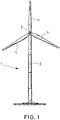
- Fig. 1 is a wind turbine 1 shown schematically.
- the wind turbine 1 has a tower 2, at its tip on a machine housing, not shown, or a nacelle a rotor hub 3 with three rotor blades 4 is arranged.
- the consisting of rotor hub 3 and rotor blades 4 rotor of the wind turbine 1 is rotatable about a substantially horizontally oriented axis of rotation.
- a rotor blade 4 is shown schematically from above.
- the rotor blade extends in the longitudinal direction of the longitudinal axis 5 of a rotor blade root 6 to a rotor blade tip 7.
- a Blattgurt 8 which receives during operation of the wind turbine 1 on the rotor blade 4 acting bending forces and the rotor blade root. 6 in the rotor hub 3 initiates.
- the rotor blade 4 extends from a profile leading edge 9 to a profile trailing edge 10th
- the area of the rotor blade root 6 is in Fig. 2 approximately the area including the transition region, which extends from the rotor blade root 6 to about the point at which attaches the line leading to the reference number for the Blattgurt 8. In this area, the rotor blade 4 aerodynamically not or only slightly effective.
- a section line AA is shown in the middle of the rotor blade 4.
- the cross-sectional profile of the rotor blade 4 at this section line AA is in Fig. 3 shown. It can be seen that the rotor blade has an upper half shell on the pressure side 11, which extends from the profile leading edge to the profile trailing edge 10, and a lower half shell on the suction side 12, which also extends from the profile leading edge 9 to the profile trailing edge 10.
- leaf straps 8, 8 ' which consist of fibrous consist with unidirectional fiber orientation in the longitudinal direction of the rotor blade 4 and are mainly responsible for dissipating bending stresses of the rotor blade 4 to the rotor blade root 6 and thus to set the rotor in rotation.
- leaf straps 8, 8 ' On both sides of the leaf straps 8, 8 'are the half-shells of the pressure side 11 and suction side 12 via webs 14, 14' connected to each other, which further stabilize the cross-sectional profile.
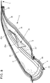
- FIG. 4 schematically shows a cross section through a rotor blade 4 in the manufacture, with a first half-shell 20 and a second half-shell 21, one of which is provided for a suction side and one for a pressure side of the rotor blade.
- a web package 19 with webs 14, 14 ' is used, wherein the webs 14, 14' lower web feet 15, 15 'and upper web feet 16, 16', the bonding surfaces for the half-shells 20, 21 represent.
- the lower web feet 15, 15 ' are already glued by means of bonds 17, 17' with the inside of the first half-shell 20.
- the bonding may, for example, have taken place in an adhesive injection process using little adhesive.
- the upper bridge feet 16, 16 ' are provided with adhesive 18, 18', on which the second, upper half-shell 21 still has to be placed.
- the web package 19 comprises a plurality of cross-connection devices, namely, in this case, transverse struts 30, 31 and diagonal struts 32, 33, which are each detachably connected to suction cups 34 with the inner surfaces of the webs.
- the struts 30 to 33 can thus be removed by loosening the suction cups 34 from the interior space between the webs 14, 14 ', so that the web package 19 after the manufacture of the rotor blade by closing the rotor blade and gluing the webs 14, 14' with the second Half shell 21 to be resolved can.
- transverse struts 30, 31 and diagonal struts 32, 33 ensures that the webs 14, 14 'remain fixed in the position in which they have been aligned with one another by the transverse connection devices 30 to 33 without being able to tilt. In this way it is ensured that tolerances in the web positioning in the first half-shell 20 and the second half-shell 21 are maintained.
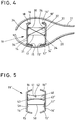
- Fig. 5 is an alternative inventive web package 19 'shown in cross section.
- the webs 14, 14 ' are connected in this case by means of two fixedly connected to the webs 14, 14' cross-connection devices.
- a sandwich panel 40 is shown with a sidecut 42 which is fixedly connected at the sides with bonds 43, 43 'to the inner sides of the webs 14, 14'.
- the waist 42 is used for weight reduction, but also a rectangular sandwich plate 40 or a plate made of another material can serve the same purpose.
- the sandwich panel 40 has centrally a lifting lug 41 or bore, into which a holding element of a web positioning device can engage in order to grasp the web package 19 'and insert it as a whole into a half shell.
- a double-T strut 50 with lateral T-legs 51, 51 '.
- the T-feet 51, 51 ' are in turn connected flat with the webs 14, 14'.
- the double-T structure also prevents tilting of the webs 14, 14 'against each other.
- this shape represents an extreme shape of a sidecut.
- Such a double-T strut 50 is preferably made of a solid material, for example a metal.
- the web packages 19, 19 'described above can be lifted into the main mold with the lower half-shell of the rotor blade by a positioning device that is designed very simply, namely as a crane, and then glued to the shells.
- cross-connection devices can also be used in the root area releasably cross-connection devices and lightweight in the blade tip area, for example made of plastic, permanently inserted cross-connection devices. Both types of cross-connection devices can be equipped with holding means, for example eyelets, for such a crane.
- Removable cross-connection devices which are removed before closing the rotor blade, can also be used in the blade-tip-side region, which is possible since the height of the webs is low in this region and tilting of the webs in this region still does not lead out of the tolerances.
- Fig. 6 is schematically illustrated a web package from one side in the neck.
- the side view is directed to a web 14 of the web packet.
- the web 14 is in the left part of Fig. 6 shown in the leaf root near area where the web 14 has a recess.
- Towards the tip of the blade, ie in Fig. 6 on the right side of the FIG. 6 are in the course of the web 14 a plurality of cross-connection elements, namely arranged in this case sandwich panels 40, which are in the region in which the web 14 is high, both in the upper and in the lower part of the web, while in the narrower region of the web 14 in the direction of the blade root tip to a series of cross-connection elements is arranged.
- the distances between the cross-connection elements can be selected to be larger in the blade tip-side region of the rotor blade than in in Fig. 6 shown blade root side area, since the mass and the lever arm, ie the height of the webs 14, 14 'in the blade tip side area is less than in the leaf root side area.
- FIGS. 7a), 7b) and 7c three different types of connecting means are shown on a web 14.
- the bridge 14 is in FIGS. 7a), 7b) and 7c ) in common that it is made of a core material 14b, which is covered on both sides by a respective laminate layer 14a, 14c.
- the core material is, for example, a PET foam or a PVC foam.
- the laminate layer consists of one or more layers of fibrous material, for example glass fibers, embedded in a resin matrix.
- connection eye 60 which has a base plate 61, laminated by means of two laminate layers 62 to the web 14.
- a hook of a cross-connection device can engage in this connection eye 60.
- FIG. 7b an alternative embodiment of a compound is shown, wherein the web 14 has a blind hole 65 into which a connection eye 60 is screwed with a screw 64. This connection eye 60 with the screw 64 can be removed from the blind hole 65 again.
- the web 14 has a through opening 73, through which one end of a bolt 70 is inserted with an external thread.
- On both sides of the web is on the external thread of the bolt 70 each have a washer 71, 71 'and a nut 72, 72' plugged or screwed, whereby the bolt 70th is fixed on the web 14.
- the nuts 72, 72 ' By loosening the nuts 72, 72 ', the bolt 70 is also removable from the web 14 again.
- Fig. 8 is a first, lower half-shell 20 of a rotor blade 4 in a main form 80 for the first, lower half-shell 20 shown schematically in perspective.
- the main mold 80 extends from the blade root 6 to the blade tip 7.
- the shell material of the first lower half shell 20 is inserted.
- the parts of the mold on the profile leading edge 9 and on the profile trailing edge 10 are also identified.
- the main mold 80 rests on an elongated bearing block 23 and a transverse bearing block 22 in the blade tip region.
- a trailing edge web 25 or TEP web is shown, which is used for larger rotor blades.
- This trailing edge web 25 has a kink 26, so that the trailing edge web 25 has a blade root-side trailing edge web portion 25a and a blade tip-side trailing edge web portion 25b.
- the blade root-side trailing edge web portion 25a becomes significantly narrower in the direction of the rotor blade tip 7, which corresponds to the profile of the profile in the longitudinal direction of the rotor blade 4.
- the bend 26 of the trailing edge web 25 is necessary because the distance between the profile leading edge 9 and trailing edge 10 of the rotor blade 4 in the direction of the rotor blade tip 7 decreases towards. Because of the bend 26, the trailing edge web 25 is usually made in two parts and then glued together. The trailing edge web 25 may be part of a web package, so be supported against the rear main web 14 ', or it may be stabilized by means of its own support device relative to the first, lower half shell 20 of the rotor blade 4.
Landscapes
- Engineering & Computer Science (AREA)
- Life Sciences & Earth Sciences (AREA)
- Sustainable Development (AREA)
- Sustainable Energy (AREA)
- Chemical & Material Sciences (AREA)
- Combustion & Propulsion (AREA)
- Mechanical Engineering (AREA)
- General Engineering & Computer Science (AREA)
- Wind Motors (AREA)
- Turbine Rotor Nozzle Sealing (AREA)
Claims (11)
- Procédé de fabrication d'une pale (4) d'une éolienne, dans lequel la pale est réalisée à partir de demi-coques (20, 21) pour un côté d'aspiration (12) et d'un côté de pression (11), lesquelles demi-coques sont reliées l'une à l'autre au sein de la pale (4) au moyen d'au moins deux éléments de liaison (14, 14', 25) s'étendant dans le sens longitudinal de la pale (4), les éléments de liaison (14, 14', 25) étant d'abord positionnés sur une première demi-coque (20) et reliés à la première demi-coque (20) par collage, la pale (4) étant ensuite fermée, une deuxième demi-coque (21) étant reliée à la première demi-coque (20) au moyen des éléments de liaison (14, 14', 25), ou la première demi-coque (20) est reliée à la deuxième demi-coque (21) au moyen des éléments de liaison (14, 14', 25), les demi-coques (20, 21) étant collées l'une à l'autre et les éléments de liaison (14, 14', 25) étant collés à la deuxième demi-coque (21), caractérisé en ce que les éléments de liaison (14, 14', 25) d'un ensemble formant élément de liaison (19, 19') sont reliés au moyen d'une pluralité d'organes de liaison transversale (30 - 33, 40, 50) d'une façon stables à l'égard d'un basculement, avant que les éléments de liaison (14, 14', 25) soient positionnés sur la première demi-coque (20), une partie ou la totalité des dispositifs de liaison transversale (30 - 33, 40, 50) étant aptes à être retirés avant la fermeture de la pale (4).
- Procédé selon la revendication 1, caractérisé en ce que les éléments de liaison (14, 14', 25) sont positionnés ensemble dans la première demi-coque (20) sous la forme d'un ensemble d'éléments de liaison (19, 19') reliés entre eux au moyen d'un dispositif de positionnement d'éléments de liaison, en particulier la fabrication des éléments de liaison (19, 19') étant réalisée à l'extérieur de la pale (4).
- Procédé selon la revendication 1 ou la revendication 2, caractérisé en ce que le collage des éléments de liaison (14, 14', 25) avec les demi-coques est réalisé sous la forme d'un collage avec des bandes de tôle (9 - 9') agencées dans la direction longitudinale des demi-coques (20, 21).
- Ensemble formant élément de liaison (19, 19') pour une pale (4) d'une éolienne (1) comprenant au moins deux éléments de liaison (14, 14', 25) s'étendant dans la direction longitudinale de la pale (4) et une pluralité d'organes de liaison transversale (30 - 33) au moyen de laquelle les éléments de liaison (14, 14', 25) sont reliés ou aptes à être reliés les uns aux autres d'une manière résistante au basculement, au moins une partie des organes de liaison transversale (30 - 33, 40, 50) et les éléments de liaison (14, 14', 25, 50) étant reliés les uns aux autres, caractérisé en ce qu'au moins une partie des organes de liaison transversale (30 - 33, 40, 50) comporte des moyens de maintien (41) pour un dispositif de positionnement des éléments de liaison.
- Ensemble formant élément de liaison (19, 19') selon la revendication 4, dans lequel les assemblages sont réalisés ou aptes à être réalisés au moyen de ventouses (34), de vis (64), de boulons (70) et/ou de crochets et d'oeillets (60), en particulier avec des moyens de connexion ou de liaison (61) laminés ou stratifiés, des trous borgnes (65) et / ou des ouvertures traversantes (73) sur et / ou dans les éléments de liaison (14, 14', 25).
- Ensemble formant élément de liaison selon la revendication 4 ou la revendication 5, dans lequel au moins une partie des organes de liaison transversale (30 - 33, 40, 50) est reliée de manière fixe aux éléments de liaison (14, 14', 25), en particulier par collage et / ou laminage ou stratification.
- Ensemble formant élément de liaison (19, 19') selon l'une quelconque des revendications 4 à 6, caractérisé en ce que les organes de liaison transversale (30 - 33, 40, 50) sont sous la forme de renforts métalliques, de renforts en matière plastique, d'entretoises en métal ou en matière plastique et / ou sous forme de corps plat rectangulaires ou cintrés, en particulier sous la forme plaques (40) à structure sandwich ayant des composites de fibres et un matériau formant une âme.
- Ensemble formant élément de liaison selon l'une des revendications 4 à 7, caractérisé en ce que, pour sécuriser les éléments de liaison (14, 14', 25) contre le basculement, au moins une partie des organes de liaison transversale (32, 33) est disposée entre les éléments de liaison (14, 14', 25) sensiblement en diagonale et / ou en diagonale d'une façon transversale.
- Ensemble formant élément de liaison (19, 19') selon l'une des revendications 4 à 8, caractérisé en ce qu'un troisième élément de liaison (25) est agencé en plus des deux éléments de liaison principaux (14, 14'), qui est agencé jusqu'au bord de fuite (10) et s'étend sensiblement parallèlement aux éléments de liaison (14, 14') principaux.
- Pale (4) d'une éolienne (1) ayant un ensemble formant élément de liaison (19, 19') selon l'une quelconque des revendications 4 à 9, en particulier réalisé ou apte à être réalisé par un procédé selon l'une quelconque des revendications 1 à 3.
- Éolienne (1) ayant une ou plusieurs pales (4) selon la revendication 10.
Applications Claiming Priority (2)
| Application Number | Priority Date | Filing Date | Title |
|---|---|---|---|
| DE102011080869A DE102011080869A1 (de) | 2011-08-12 | 2011-08-12 | Verfahren zum Herstellen eines Rotorblatts einer Windenergieanlage, Stegpaket, Rotorblatt und Windenergieanlage |
| PCT/EP2012/003296 WO2013023745A1 (fr) | 2011-08-12 | 2012-08-02 | Procédé de fabrication d'une pale d'une éolienne, ensemble d'éléments de liaison, pale et éolienne |
Publications (2)
| Publication Number | Publication Date |
|---|---|
| EP2742234A1 EP2742234A1 (fr) | 2014-06-18 |
| EP2742234B1 true EP2742234B1 (fr) | 2018-01-17 |
Family
ID=46690466
Family Applications (1)
| Application Number | Title | Priority Date | Filing Date |
|---|---|---|---|
| EP12748165.3A Not-in-force EP2742234B1 (fr) | 2011-08-12 | 2012-08-02 | Procédé de fabrication d'une pale d'une éolienne, ensemble d'éléments de liaison, pale et éolienne |
Country Status (5)
| Country | Link |
|---|---|
| EP (1) | EP2742234B1 (fr) |
| DE (1) | DE102011080869A1 (fr) |
| DK (1) | DK2742234T3 (fr) |
| ES (1) | ES2664612T3 (fr) |
| WO (1) | WO2013023745A1 (fr) |
Cited By (4)
| Publication number | Priority date | Publication date | Assignee | Title |
|---|---|---|---|---|
| WO2020216924A1 (fr) | 2019-04-26 | 2020-10-29 | Blade Dynamics Limited | Procédé de production d'une pale d'éolienne et pale d'éolienne |
| EP3960428A1 (fr) | 2020-08-28 | 2022-03-02 | Nordex Energy SE & Co. KG | Procédés de montage de pale de rotor d'éolienne |
| US20220203627A1 (en) * | 2020-12-28 | 2022-06-30 | Lm Wind Power A/S | Distance member for connecting wind turbine blade shear webs |
| EP4227521A1 (fr) * | 2022-02-14 | 2023-08-16 | LM Wind Power A/S | Ensembles âmes de longeron et ensembles fixation adaptés et procédés |
Families Citing this family (23)
| Publication number | Priority date | Publication date | Assignee | Title |
|---|---|---|---|---|
| DE102013224392B4 (de) * | 2013-11-28 | 2016-01-14 | Senvion Gmbh | Stegsetzvorrichtung, Steg und Fertigungsverfahren für ein Rotorblatt einer Windenergieanlage |
| US9759183B2 (en) | 2015-01-05 | 2017-09-12 | General Electric Company | System and method for attaching components to a web in a wind turbine rotor blade |
| US9869297B2 (en) | 2015-05-07 | 2018-01-16 | General Electric Company | Attachment method and system to install components, such as vortex generators, to a wind turbine blade |
| US9869296B2 (en) | 2015-05-07 | 2018-01-16 | General Electric Company | Attachment method and system to install components, such as tip extensions and winglets, to a wind turbine blade |
| US9869295B2 (en) | 2015-05-07 | 2018-01-16 | General Electric Company | Attachment method to install components, such as tip extensions and winglets, to a wind turbine blade, as well as the wind turbine blade and component |
| US10100805B2 (en) | 2015-10-12 | 2018-10-16 | General Electric Compant | Tip extension assembly for a wind turbine rotor blade |
| DE102016000292A1 (de) * | 2016-01-15 | 2017-07-20 | Senvion Gmbh | Rotorblatt einer Windenergieanlage und Verfahren zum Herstellen eines Rotorblatts |
| DE102016000294A1 (de) * | 2016-01-15 | 2017-07-20 | Senvion Gmbh | Rotorblatt mit Verstärkungs-Fasergelege und Verfahren zum Herstellen eines solchen Rotorblatts |
| US10443579B2 (en) | 2016-11-15 | 2019-10-15 | General Electric Company | Tip extensions for wind turbine rotor blades and methods of installing same |
| US10830206B2 (en) | 2017-02-03 | 2020-11-10 | General Electric Company | Methods for manufacturing wind turbine rotor blades and components thereof |
| US11098691B2 (en) | 2017-02-03 | 2021-08-24 | General Electric Company | Methods for manufacturing wind turbine rotor blades and components thereof |
| US11448182B2 (en) | 2017-04-05 | 2022-09-20 | Vestas Wind Systems A/S | Relating to wind turbine blade manufacture |
| US11248582B2 (en) | 2017-11-21 | 2022-02-15 | General Electric Company | Multiple material combinations for printed reinforcement structures of rotor blades |
| US10773464B2 (en) | 2017-11-21 | 2020-09-15 | General Electric Company | Method for manufacturing composite airfoils |
| US10920745B2 (en) | 2017-11-21 | 2021-02-16 | General Electric Company | Wind turbine rotor blade components and methods of manufacturing the same |
| US11040503B2 (en) | 2017-11-21 | 2021-06-22 | General Electric Company | Apparatus for manufacturing composite airfoils |
| US11390013B2 (en) | 2017-11-21 | 2022-07-19 | General Electric Company | Vacuum forming mold assembly and associated methods |
| US11668275B2 (en) | 2017-11-21 | 2023-06-06 | General Electric Company | Methods for manufacturing an outer skin of a rotor blade |
| US10913216B2 (en) | 2017-11-21 | 2021-02-09 | General Electric Company | Methods for manufacturing wind turbine rotor blade panels having printed grid structures |
| US10865769B2 (en) | 2017-11-21 | 2020-12-15 | General Electric Company | Methods for manufacturing wind turbine rotor blade panels having printed grid structures |
| US10821652B2 (en) | 2017-11-21 | 2020-11-03 | General Electric Company | Vacuum forming mold assembly and method for creating a vacuum forming mold assembly |
| US11035339B2 (en) | 2018-03-26 | 2021-06-15 | General Electric Company | Shear web assembly interconnected with additive manufactured components |
| US10821696B2 (en) | 2018-03-26 | 2020-11-03 | General Electric Company | Methods for manufacturing flatback airfoils for wind turbine rotor blades |
Family Cites Families (6)
| Publication number | Priority date | Publication date | Assignee | Title |
|---|---|---|---|---|
| WO2008089765A2 (fr) * | 2007-01-25 | 2008-07-31 | Danmarks Tekniske Universitet | Pale d'éolienne renforcée |
| DE102008022548A1 (de) * | 2008-05-07 | 2009-11-12 | Nordex Energy Gmbh | Rotorblatt für eine Windenergieanlage |
| ES2383061T3 (es) * | 2008-06-24 | 2012-06-18 | Bladena Aps | Paleta de turnina eólica reforzada |
| DE112010000962A5 (de) * | 2009-03-05 | 2012-08-02 | Michaela Kress-Haase | Windkraftanlage und zugehöriges Herstellungsverfahren |
| DE102009040515A1 (de) * | 2009-09-03 | 2011-03-10 | Grimm, Friedrich, Prof. Dipl.-Ing. | Rotorblatt für eine Windturbine mit horizontaler Rotationsachse |
| DE102010042327A1 (de) | 2010-10-12 | 2012-04-12 | Repower Systems Se | Fertigung eines Rotorblattes einer Windenergieanlage |
-
2011
- 2011-08-12 DE DE102011080869A patent/DE102011080869A1/de not_active Withdrawn
-
2012
- 2012-08-02 WO PCT/EP2012/003296 patent/WO2013023745A1/fr active Application Filing
- 2012-08-02 ES ES12748165.3T patent/ES2664612T3/es active Active
- 2012-08-02 DK DK12748165.3T patent/DK2742234T3/en active
- 2012-08-02 EP EP12748165.3A patent/EP2742234B1/fr not_active Not-in-force
Cited By (7)
| Publication number | Priority date | Publication date | Assignee | Title |
|---|---|---|---|---|
| WO2020216924A1 (fr) | 2019-04-26 | 2020-10-29 | Blade Dynamics Limited | Procédé de production d'une pale d'éolienne et pale d'éolienne |
| US11988190B2 (en) | 2019-04-26 | 2024-05-21 | Blade Dynamics Limited | Method for producing a wind turbine blade and wind turbine blade |
| EP3960428A1 (fr) | 2020-08-28 | 2022-03-02 | Nordex Energy SE & Co. KG | Procédés de montage de pale de rotor d'éolienne |
| US20220203627A1 (en) * | 2020-12-28 | 2022-06-30 | Lm Wind Power A/S | Distance member for connecting wind turbine blade shear webs |
| US11667087B2 (en) * | 2020-12-28 | 2023-06-06 | Lm Wind Power A/S | Distance member for connecting wind turbine blade shear webs |
| EP4227521A1 (fr) * | 2022-02-14 | 2023-08-16 | LM Wind Power A/S | Ensembles âmes de longeron et ensembles fixation adaptés et procédés |
| WO2023152357A1 (fr) * | 2022-02-14 | 2023-08-17 | Lm Wind Power A/S | Ensembles de bandes de longeron et ensembles de fixation appropriés et procédés |
Also Published As
| Publication number | Publication date |
|---|---|
| DK2742234T3 (en) | 2018-04-30 |
| ES2664612T3 (es) | 2018-04-20 |
| EP2742234A1 (fr) | 2014-06-18 |
| DE102011080869A1 (de) | 2013-02-14 |
| WO2013023745A1 (fr) | 2013-02-21 |
Similar Documents
| Publication | Publication Date | Title |
|---|---|---|
| EP2742234B1 (fr) | Procédé de fabrication d'une pale d'une éolienne, ensemble d'éléments de liaison, pale et éolienne | |
| DE102011078951C5 (de) | Verfahren zum Herstellen eines Rotorblatts für eine Windenergieanlage | |
| EP2363599B2 (fr) | Pale de rotor pour une éolienne, éolienne et procédé de fabrication d'une pale de rotor | |
| EP1525395B1 (fr) | Procede de production d'une pale de rotor, pale de rotor et eolienne correspondantes | |
| DE602005001391T2 (de) | Verfahren zur Herstellung eines Windturbinenblatts, eine Produktionsanlage von Windturbinenblättern und Verwendung hiervon | |
| DE102007020338B4 (de) | Verfahren zum Herstellen von Blättern | |
| AT510694B1 (de) | Modul zum halten von mindestens einer hülse | |
| EP2182203B2 (fr) | Pale d'éolienne comprenant une extension | |
| EP0019691A1 (fr) | Pale de rotor constituée d'éléments assemblés juxtaposés | |
| EP3018342B1 (fr) | Procede de fabrication d'une pale de rotor d'eolienne | |
| WO2018029240A1 (fr) | Membrure en éléments préfabriqués pourvues de non-tissé et son procédé de production | |
| EP3129644B1 (fr) | Pale de rotor d'une éolienne | |
| EP3299613B1 (fr) | Pale de rotor ayant un élément de liaison d'extrémité | |
| EP3486476B1 (fr) | Entretoise pour une pale de rotor d'une éolienne et procédé de fabrication d'une entretoise | |
| EP0506721B1 (fr) | Element structural en fibre technique sollicite en traction | |
| EP3482918B1 (fr) | Procédé de fabrication d'une entretoise d'une pale de rotor d'une éolienne | |
| EP2985138B1 (fr) | Pale pour une éolienne et procédé de fabrication de celle-ci | |
| EP3360671B1 (fr) | Pré-moule rotatif pour une préforme | |
| EP3578349B1 (fr) | Procédé et dispositif de fabrication d'une pâle de rotor pour une éolienne | |
| DE102011077609A1 (de) | Fertigung einer Rotorblattschale | |
| WO2023247714A1 (fr) | Procédé de production d'un élément composite à base de fibres et élément creux composite à base de fibres, et éolienne associée | |
| EP3015702A1 (fr) | Pale de rotor pour une eolienne et procede de fabrication d'une pale de rotor | |
| DE102016014908A1 (de) | Rotorblatt, Windenergieanlage mit einem Rotorblatt und Reparatursatz und Verfahren zum Verstärken eines Rotorblatts |
Legal Events
| Date | Code | Title | Description |
|---|---|---|---|
| PUAI | Public reference made under article 153(3) epc to a published international application that has entered the european phase |
Free format text: ORIGINAL CODE: 0009012 |
|
| 17P | Request for examination filed |
Effective date: 20140130 |
|
| AK | Designated contracting states |
Kind code of ref document: A1 Designated state(s): AL AT BE BG CH CY CZ DE DK EE ES FI FR GB GR HR HU IE IS IT LI LT LU LV MC MK MT NL NO PL PT RO RS SE SI SK SM TR |
|
| DAX | Request for extension of the european patent (deleted) | ||
| RAP1 | Party data changed (applicant data changed or rights of an application transferred) |
Owner name: SENVION SE |
|
| RAP1 | Party data changed (applicant data changed or rights of an application transferred) |
Owner name: SENVION GMBH |
|
| 17Q | First examination report despatched |
Effective date: 20160111 |
|
| GRAP | Despatch of communication of intention to grant a patent |
Free format text: ORIGINAL CODE: EPIDOSNIGR1 |
|
| INTG | Intention to grant announced |
Effective date: 20170913 |
|
| GRAS | Grant fee paid |
Free format text: ORIGINAL CODE: EPIDOSNIGR3 |
|
| GRAA | (expected) grant |
Free format text: ORIGINAL CODE: 0009210 |
|
| AK | Designated contracting states |
Kind code of ref document: B1 Designated state(s): AL AT BE BG CH CY CZ DE DK EE ES FI FR GB GR HR HU IE IS IT LI LT LU LV MC MK MT NL NO PL PT RO RS SE SI SK SM TR |
|
| REG | Reference to a national code |
Ref country code: GB Ref legal event code: FG4D Free format text: NOT ENGLISH |
|
| REG | Reference to a national code |
Ref country code: CH Ref legal event code: EP |
|
| REG | Reference to a national code |
Ref country code: IE Ref legal event code: FG4D Free format text: LANGUAGE OF EP DOCUMENT: GERMAN |
|
| REG | Reference to a national code |
Ref country code: AT Ref legal event code: REF Ref document number: 964615 Country of ref document: AT Kind code of ref document: T Effective date: 20180215 |
|
| REG | Reference to a national code |
Ref country code: DE Ref legal event code: R096 Ref document number: 502012012033 Country of ref document: DE |
|
| REG | Reference to a national code |
Ref country code: ES Ref legal event code: FG2A Ref document number: 2664612 Country of ref document: ES Kind code of ref document: T3 Effective date: 20180420 |
|
| REG | Reference to a national code |
Ref country code: DK Ref legal event code: T3 Effective date: 20180426 |
|
| REG | Reference to a national code |
Ref country code: NL Ref legal event code: MP Effective date: 20180117 |
|
| REG | Reference to a national code |
Ref country code: LT Ref legal event code: MG4D |
|
| PG25 | Lapsed in a contracting state [announced via postgrant information from national office to epo] |
Ref country code: NL Free format text: LAPSE BECAUSE OF FAILURE TO SUBMIT A TRANSLATION OF THE DESCRIPTION OR TO PAY THE FEE WITHIN THE PRESCRIBED TIME-LIMIT Effective date: 20180117 |
|
| PG25 | Lapsed in a contracting state [announced via postgrant information from national office to epo] |
Ref country code: FI Free format text: LAPSE BECAUSE OF FAILURE TO SUBMIT A TRANSLATION OF THE DESCRIPTION OR TO PAY THE FEE WITHIN THE PRESCRIBED TIME-LIMIT Effective date: 20180117 Ref country code: LT Free format text: LAPSE BECAUSE OF FAILURE TO SUBMIT A TRANSLATION OF THE DESCRIPTION OR TO PAY THE FEE WITHIN THE PRESCRIBED TIME-LIMIT Effective date: 20180117 Ref country code: HR Free format text: LAPSE BECAUSE OF FAILURE TO SUBMIT A TRANSLATION OF THE DESCRIPTION OR TO PAY THE FEE WITHIN THE PRESCRIBED TIME-LIMIT Effective date: 20180117 Ref country code: CY Free format text: LAPSE BECAUSE OF FAILURE TO SUBMIT A TRANSLATION OF THE DESCRIPTION OR TO PAY THE FEE WITHIN THE PRESCRIBED TIME-LIMIT Effective date: 20180117 Ref country code: NO Free format text: LAPSE BECAUSE OF FAILURE TO SUBMIT A TRANSLATION OF THE DESCRIPTION OR TO PAY THE FEE WITHIN THE PRESCRIBED TIME-LIMIT Effective date: 20180417 |
|
| REG | Reference to a national code |
Ref country code: FR Ref legal event code: PLFP Year of fee payment: 7 |
|
| PG25 | Lapsed in a contracting state [announced via postgrant information from national office to epo] |
Ref country code: IS Free format text: LAPSE BECAUSE OF FAILURE TO SUBMIT A TRANSLATION OF THE DESCRIPTION OR TO PAY THE FEE WITHIN THE PRESCRIBED TIME-LIMIT Effective date: 20180517 Ref country code: BG Free format text: LAPSE BECAUSE OF FAILURE TO SUBMIT A TRANSLATION OF THE DESCRIPTION OR TO PAY THE FEE WITHIN THE PRESCRIBED TIME-LIMIT Effective date: 20180417 Ref country code: RS Free format text: LAPSE BECAUSE OF FAILURE TO SUBMIT A TRANSLATION OF THE DESCRIPTION OR TO PAY THE FEE WITHIN THE PRESCRIBED TIME-LIMIT Effective date: 20180117 Ref country code: SE Free format text: LAPSE BECAUSE OF FAILURE TO SUBMIT A TRANSLATION OF THE DESCRIPTION OR TO PAY THE FEE WITHIN THE PRESCRIBED TIME-LIMIT Effective date: 20180117 Ref country code: LV Free format text: LAPSE BECAUSE OF FAILURE TO SUBMIT A TRANSLATION OF THE DESCRIPTION OR TO PAY THE FEE WITHIN THE PRESCRIBED TIME-LIMIT Effective date: 20180117 Ref country code: GR Free format text: LAPSE BECAUSE OF FAILURE TO SUBMIT A TRANSLATION OF THE DESCRIPTION OR TO PAY THE FEE WITHIN THE PRESCRIBED TIME-LIMIT Effective date: 20180418 Ref country code: PL Free format text: LAPSE BECAUSE OF FAILURE TO SUBMIT A TRANSLATION OF THE DESCRIPTION OR TO PAY THE FEE WITHIN THE PRESCRIBED TIME-LIMIT Effective date: 20180117 |
|
| PG25 | Lapsed in a contracting state [announced via postgrant information from national office to epo] |
Ref country code: MT Free format text: LAPSE BECAUSE OF FAILURE TO SUBMIT A TRANSLATION OF THE DESCRIPTION OR TO PAY THE FEE WITHIN THE PRESCRIBED TIME-LIMIT Effective date: 20180117 |
|
| REG | Reference to a national code |
Ref country code: DE Ref legal event code: R097 Ref document number: 502012012033 Country of ref document: DE |
|
| PG25 | Lapsed in a contracting state [announced via postgrant information from national office to epo] |
Ref country code: EE Free format text: LAPSE BECAUSE OF FAILURE TO SUBMIT A TRANSLATION OF THE DESCRIPTION OR TO PAY THE FEE WITHIN THE PRESCRIBED TIME-LIMIT Effective date: 20180117 Ref country code: IT Free format text: LAPSE BECAUSE OF FAILURE TO SUBMIT A TRANSLATION OF THE DESCRIPTION OR TO PAY THE FEE WITHIN THE PRESCRIBED TIME-LIMIT Effective date: 20180117 Ref country code: RO Free format text: LAPSE BECAUSE OF FAILURE TO SUBMIT A TRANSLATION OF THE DESCRIPTION OR TO PAY THE FEE WITHIN THE PRESCRIBED TIME-LIMIT Effective date: 20180117 Ref country code: AL Free format text: LAPSE BECAUSE OF FAILURE TO SUBMIT A TRANSLATION OF THE DESCRIPTION OR TO PAY THE FEE WITHIN THE PRESCRIBED TIME-LIMIT Effective date: 20180117 |
|
| PLBE | No opposition filed within time limit |
Free format text: ORIGINAL CODE: 0009261 |
|
| STAA | Information on the status of an ep patent application or granted ep patent |
Free format text: STATUS: NO OPPOSITION FILED WITHIN TIME LIMIT |
|
| PG25 | Lapsed in a contracting state [announced via postgrant information from national office to epo] |
Ref country code: SK Free format text: LAPSE BECAUSE OF FAILURE TO SUBMIT A TRANSLATION OF THE DESCRIPTION OR TO PAY THE FEE WITHIN THE PRESCRIBED TIME-LIMIT Effective date: 20180117 Ref country code: SM Free format text: LAPSE BECAUSE OF FAILURE TO SUBMIT A TRANSLATION OF THE DESCRIPTION OR TO PAY THE FEE WITHIN THE PRESCRIBED TIME-LIMIT Effective date: 20180117 Ref country code: CZ Free format text: LAPSE BECAUSE OF FAILURE TO SUBMIT A TRANSLATION OF THE DESCRIPTION OR TO PAY THE FEE WITHIN THE PRESCRIBED TIME-LIMIT Effective date: 20180117 |
|
| 26N | No opposition filed |
Effective date: 20181018 |
|
| PG25 | Lapsed in a contracting state [announced via postgrant information from national office to epo] |
Ref country code: SI Free format text: LAPSE BECAUSE OF FAILURE TO SUBMIT A TRANSLATION OF THE DESCRIPTION OR TO PAY THE FEE WITHIN THE PRESCRIBED TIME-LIMIT Effective date: 20180117 |
|
| PG25 | Lapsed in a contracting state [announced via postgrant information from national office to epo] |
Ref country code: MC Free format text: LAPSE BECAUSE OF FAILURE TO SUBMIT A TRANSLATION OF THE DESCRIPTION OR TO PAY THE FEE WITHIN THE PRESCRIBED TIME-LIMIT Effective date: 20180117 |
|
| REG | Reference to a national code |
Ref country code: CH Ref legal event code: PL |
|
| PG25 | Lapsed in a contracting state [announced via postgrant information from national office to epo] |
Ref country code: LI Free format text: LAPSE BECAUSE OF NON-PAYMENT OF DUE FEES Effective date: 20180831 Ref country code: CH Free format text: LAPSE BECAUSE OF NON-PAYMENT OF DUE FEES Effective date: 20180831 Ref country code: LU Free format text: LAPSE BECAUSE OF NON-PAYMENT OF DUE FEES Effective date: 20180802 |
|
| REG | Reference to a national code |
Ref country code: BE Ref legal event code: MM Effective date: 20180831 |
|
| REG | Reference to a national code |
Ref country code: IE Ref legal event code: MM4A |
|
| PG25 | Lapsed in a contracting state [announced via postgrant information from national office to epo] |
Ref country code: IE Free format text: LAPSE BECAUSE OF NON-PAYMENT OF DUE FEES Effective date: 20180802 |
|
| PG25 | Lapsed in a contracting state [announced via postgrant information from national office to epo] |
Ref country code: BE Free format text: LAPSE BECAUSE OF NON-PAYMENT OF DUE FEES Effective date: 20180831 |
|
| REG | Reference to a national code |
Ref country code: AT Ref legal event code: MM01 Ref document number: 964615 Country of ref document: AT Kind code of ref document: T Effective date: 20180802 |
|
| PG25 | Lapsed in a contracting state [announced via postgrant information from national office to epo] |
Ref country code: AT Free format text: LAPSE BECAUSE OF NON-PAYMENT OF DUE FEES Effective date: 20180802 |
|
| PG25 | Lapsed in a contracting state [announced via postgrant information from national office to epo] |
Ref country code: TR Free format text: LAPSE BECAUSE OF FAILURE TO SUBMIT A TRANSLATION OF THE DESCRIPTION OR TO PAY THE FEE WITHIN THE PRESCRIBED TIME-LIMIT Effective date: 20180117 |
|
| PG25 | Lapsed in a contracting state [announced via postgrant information from national office to epo] |
Ref country code: PT Free format text: LAPSE BECAUSE OF FAILURE TO SUBMIT A TRANSLATION OF THE DESCRIPTION OR TO PAY THE FEE WITHIN THE PRESCRIBED TIME-LIMIT Effective date: 20180117 Ref country code: HU Free format text: LAPSE BECAUSE OF FAILURE TO SUBMIT A TRANSLATION OF THE DESCRIPTION OR TO PAY THE FEE WITHIN THE PRESCRIBED TIME-LIMIT; INVALID AB INITIO Effective date: 20120802 |
|
| PG25 | Lapsed in a contracting state [announced via postgrant information from national office to epo] |
Ref country code: MK Free format text: LAPSE BECAUSE OF NON-PAYMENT OF DUE FEES Effective date: 20180117 |
|
| PGFP | Annual fee paid to national office [announced via postgrant information from national office to epo] |
Ref country code: FR Payment date: 20210823 Year of fee payment: 10 |
|
| PGFP | Annual fee paid to national office [announced via postgrant information from national office to epo] |
Ref country code: DK Payment date: 20210820 Year of fee payment: 10 Ref country code: ES Payment date: 20210917 Year of fee payment: 10 Ref country code: GB Payment date: 20210824 Year of fee payment: 10 Ref country code: DE Payment date: 20210819 Year of fee payment: 10 |
|
| REG | Reference to a national code |
Ref country code: DE Ref legal event code: R081 Ref document number: 502012012033 Country of ref document: DE Owner name: SIEMENS GAMESA RENEWABLE ENERGY SERVICE GMBH, DE Free format text: FORMER OWNER: SENVION GMBH, 22297 HAMBURG, DE |
|
| REG | Reference to a national code |
Ref country code: DE Ref legal event code: R119 Ref document number: 502012012033 Country of ref document: DE |
|
| REG | Reference to a national code |
Ref country code: DK Ref legal event code: EBP Effective date: 20220831 |
|
| GBPC | Gb: european patent ceased through non-payment of renewal fee |
Effective date: 20220802 |
|
| PG25 | Lapsed in a contracting state [announced via postgrant information from national office to epo] |
Ref country code: FR Free format text: LAPSE BECAUSE OF NON-PAYMENT OF DUE FEES Effective date: 20220831 Ref country code: DK Free format text: LAPSE BECAUSE OF NON-PAYMENT OF DUE FEES Effective date: 20220831 Ref country code: DE Free format text: LAPSE BECAUSE OF NON-PAYMENT OF DUE FEES Effective date: 20230301 |
|
| REG | Reference to a national code |
Ref country code: ES Ref legal event code: FD2A Effective date: 20230928 |
|
| PG25 | Lapsed in a contracting state [announced via postgrant information from national office to epo] |
Ref country code: GB Free format text: LAPSE BECAUSE OF NON-PAYMENT OF DUE FEES Effective date: 20220802 Ref country code: ES Free format text: LAPSE BECAUSE OF NON-PAYMENT OF DUE FEES Effective date: 20220803 |