EP2741450B1 - Systems for synchrophasor data management - Google Patents
Systems for synchrophasor data management Download PDFInfo
- Publication number
- EP2741450B1 EP2741450B1 EP13196013.0A EP13196013A EP2741450B1 EP 2741450 B1 EP2741450 B1 EP 2741450B1 EP 13196013 A EP13196013 A EP 13196013A EP 2741450 B1 EP2741450 B1 EP 2741450B1
- Authority
- EP
- European Patent Office
- Prior art keywords
- data
- protocol
- pmu
- inputs
- pdc
- Prior art date
- Legal status (The legal status is an assumption and is not a legal conclusion. Google has not performed a legal analysis and makes no representation as to the accuracy of the status listed.)
- Active
Links
Images


Classifications
-
- G—PHYSICS
- G06—COMPUTING OR CALCULATING; COUNTING
- G06F—ELECTRIC DIGITAL DATA PROCESSING
- G06F16/00—Information retrieval; Database structures therefor; File system structures therefor
- G06F16/20—Information retrieval; Database structures therefor; File system structures therefor of structured data, e.g. relational data
- G06F16/25—Integrating or interfacing systems involving database management systems
- G06F16/258—Data format conversion from or to a database
-
- G—PHYSICS
- G01—MEASURING; TESTING
- G01R—MEASURING ELECTRIC VARIABLES; MEASURING MAGNETIC VARIABLES
- G01R25/00—Arrangements for measuring phase angle between a voltage and a current or between voltages or currents
-
- G—PHYSICS
- G01—MEASURING; TESTING
- G01R—MEASURING ELECTRIC VARIABLES; MEASURING MAGNETIC VARIABLES
- G01R19/00—Arrangements for measuring currents or voltages or for indicating presence or sign thereof
- G01R19/25—Arrangements for measuring currents or voltages or for indicating presence or sign thereof using digital measurement techniques
- G01R19/2513—Arrangements for monitoring electric power systems, e.g. power lines or loads; Logging
-
- G—PHYSICS
- G01—MEASURING; TESTING
- G01R—MEASURING ELECTRIC VARIABLES; MEASURING MAGNETIC VARIABLES
- G01R21/00—Arrangements for measuring electric power or power factor
-
- G—PHYSICS
- G01—MEASURING; TESTING
- G01R—MEASURING ELECTRIC VARIABLES; MEASURING MAGNETIC VARIABLES
- G01R23/00—Arrangements for measuring frequencies; Arrangements for analysing frequency spectra
- G01R23/02—Arrangements for measuring frequency, e.g. pulse repetition rate; Arrangements for measuring period of current or voltage
-
- G—PHYSICS
- G06—COMPUTING OR CALCULATING; COUNTING
- G06F—ELECTRIC DIGITAL DATA PROCESSING
- G06F16/00—Information retrieval; Database structures therefor; File system structures therefor
- G06F16/20—Information retrieval; Database structures therefor; File system structures therefor of structured data, e.g. relational data
- G06F16/22—Indexing; Data structures therefor; Storage structures
- G06F16/2228—Indexing structures
-
- H—ELECTRICITY
- H04—ELECTRIC COMMUNICATION TECHNIQUE
- H04Q—SELECTING
- H04Q9/00—Arrangements in telecontrol or telemetry systems for selectively calling a substation from a main station, in which substation desired apparatus is selected for applying a control signal thereto or for obtaining measured values therefrom
-
- Y—GENERAL TAGGING OF NEW TECHNOLOGICAL DEVELOPMENTS; GENERAL TAGGING OF CROSS-SECTIONAL TECHNOLOGIES SPANNING OVER SEVERAL SECTIONS OF THE IPC; TECHNICAL SUBJECTS COVERED BY FORMER USPC CROSS-REFERENCE ART COLLECTIONS [XRACs] AND DIGESTS
- Y02—TECHNOLOGIES OR APPLICATIONS FOR MITIGATION OR ADAPTATION AGAINST CLIMATE CHANGE
- Y02E—REDUCTION OF GREENHOUSE GAS [GHG] EMISSIONS, RELATED TO ENERGY GENERATION, TRANSMISSION OR DISTRIBUTION
- Y02E40/00—Technologies for an efficient electrical power generation, transmission or distribution
- Y02E40/70—Smart grids as climate change mitigation technology in the energy generation sector
-
- Y—GENERAL TAGGING OF NEW TECHNOLOGICAL DEVELOPMENTS; GENERAL TAGGING OF CROSS-SECTIONAL TECHNOLOGIES SPANNING OVER SEVERAL SECTIONS OF THE IPC; TECHNICAL SUBJECTS COVERED BY FORMER USPC CROSS-REFERENCE ART COLLECTIONS [XRACs] AND DIGESTS
- Y02—TECHNOLOGIES OR APPLICATIONS FOR MITIGATION OR ADAPTATION AGAINST CLIMATE CHANGE
- Y02E—REDUCTION OF GREENHOUSE GAS [GHG] EMISSIONS, RELATED TO ENERGY GENERATION, TRANSMISSION OR DISTRIBUTION
- Y02E60/00—Enabling technologies; Technologies with a potential or indirect contribution to GHG emissions mitigation
-
- Y—GENERAL TAGGING OF NEW TECHNOLOGICAL DEVELOPMENTS; GENERAL TAGGING OF CROSS-SECTIONAL TECHNOLOGIES SPANNING OVER SEVERAL SECTIONS OF THE IPC; TECHNICAL SUBJECTS COVERED BY FORMER USPC CROSS-REFERENCE ART COLLECTIONS [XRACs] AND DIGESTS
- Y04—INFORMATION OR COMMUNICATION TECHNOLOGIES HAVING AN IMPACT ON OTHER TECHNOLOGY AREAS
- Y04S—SYSTEMS INTEGRATING TECHNOLOGIES RELATED TO POWER NETWORK OPERATION, COMMUNICATION OR INFORMATION TECHNOLOGIES FOR IMPROVING THE ELECTRICAL POWER GENERATION, TRANSMISSION, DISTRIBUTION, MANAGEMENT OR USAGE, i.e. SMART GRIDS
- Y04S10/00—Systems supporting electrical power generation, transmission or distribution
- Y04S10/22—Flexible AC transmission systems [FACTS] or power factor or reactive power compensating or correcting units
Definitions
- the subject matter disclosed herein relates to wide area monitoring of electrical grid infrastructure, and more specifically, to the management of synchrophasor data.
- a system that monitors an electrical grid may use Phasor Measurement Units (PMUs) to measure electrical signals on the electrical grid.
- the PMUs may be able to measure parameters such as frequency, voltage, current, or power.
- Certain measurements, such as phasor data may then be communicated to a Phasor Data Concentrator (PDC).
- PDC Phasor Data Concentrator
- a function of the PDC is to concentrate data from various PMUs, and to distribute the data. Accordingly, the PDC may be able to initiate communication with multiple PMUs, archive data for post event analysis, aggregate and re-transmit data, and filter/structure output datasets.
- the PDC may then output datasets to upstream devices such as other PDCs, a super PDC, or another device.
- US 2009/0088990 describes a device for monitoring and controlling various power system device and elements.
- the device includes a communications channel for receiving phasor data associated with a location on the power system and a logic engine which performs scalar, vector and/or other complex calculation based on the phasor data to provide control data or an output signal for effecting the various other power system devices or elements to provide local or wide area protection, control, and monitoring to maintain power system stability.
- Power grid applications may be used to process the data transmitted by the PDC.
- the PDC may output the datasets for analysis of power transmissions.
- the described communication between the PDCs, PMUs, and super PDCs may use the Institute of Electrical and Electronics Engineers (IEEE) protocols C37.118 and derivatives (i.e., C37.118X).
- IEEE Institute of Electrical and Electronics Engineers
- C37.118X derivatives
- a wide variety of systems may understand data transmitted by using C37.118X. It would be beneficial to improve the data management and communication of synchrophasor and related data.
- Phasor Measurement Units may be monitored by Phasor Measurement Units (PMUs) geographically located at different points on the system.
- PDC Phasor Data Concentrators
- the PDC may then concentrate the data for transmission to other systems.
- the PDC may synchronize real-time sub-second phasor data streams for use by synchrophasor applications.
- the data streams (e.g., synchrophasor datasets), may then be communicated other PDCs, other PMUs, a super PDC, and/or a visualizer.
- the techniques described herein advantageously include a Synchrophasor Data Management System (SDMS), in which the SDMS additionally includes a Synchrophasor Processor System (SPS).
- SDMS Synchrophasor Data Management System
- SPS may provide functionality equivalent to a Phasor Data Concentrator (PDC), but add functionality, such as including a virtual or pseudo-PMU.
- PDC Phasor Data Concentrator
- the SPS may provide PDC functionality with additional functionality provided by a PMU, in a single device, such as a modular computing device enclosed in a chassis having a redundant power supply and a data bus.
- the SPS may be included in a single board computer communicatively coupled to the data bus.
- the SDMS chassis may include other single board computers, which may also be attached to the data bus, such as a Historian system suitable for data storage and communication of archived data.
- the H historiann system may be included in a second single board computer communicatively coupled to the data bus and disposed inside the chassis.
- an Application system hosting a software platform providing for variety of synchrophasor applications, such as applications suitable for analyzing synchrophasor data may be included in a third single board computer communicatively coupled to the data bus and disposed inside the chassis.
- the SPS may receive data inputs in the IEEE C37.118X protocols, and/or the IEC 61850-90-5 protocol.
- the SPS may then use, for example, a protocol mapping system to map one or both protocols into an agnostic format or data structure.
- the internal processing of the incoming data may then be carried out in this agnostic format.
- the output may then be communicated to external systems in either of the two formats.
- the SPS may be more easily updated to support new protocols. Data may be received in one protocol outputted in another protocol, or in the same protocol.
- data from the SDMS may use PMU data communication techniques to communicate data additional to PMU data.
- Systems using PMU communication compatible protocols e.g., IEEE C37.118X and/or IEC 61850-90-5 may then retrieve the data and extract the alerts and diagnostics.
- the described SDMS/upgraded PDC and the PMUs may be configured in a tiered monitoring system such as the one depicted in FIG. 1 .
- FIG. 1 is a schematic diagram of a tiered monitoring system 2.
- a PMU 4 may take measurements of a system, such as an electrical power grid.
- the PMU 4 may be able to measure parameters such as frequency, voltage, current, and/or power.
- the PMUs 4 may then transmit the measurements as phasor data, to PDCs 6 through a network 8 such as a Local Area Network (LAN) or a Wide Area Network (WAN).
- LAN Local Area Network
- WAN Wide Area Network
- the PDC 6 may synchronize real-time sub-second phasor data streams for use by synchrophasor applications, time align the measurements, filter the measurements, and so on.
- the synchronization may include using an external clock, such as a Global Positioning System (GPS) clock or an atomic clock.
- GPS Global Positioning System
- the measurements may be time aligned in order to give context to the measurement.
- the PDC may output a dataset to other devices such as other PDCs 6 or a super PDC 10.
- one PDC 6 may receive inputs from multiple PMUs 4 at the same rate or at varying data rates. With the ability to transmit measurements over the network 8, the PDCs 6 may be located in a different geographic location from the PMUs 4 that they receive measurements from. As in the illustrated embodiment, some substations 12 may include only PMUs 4. These PMUs 4 may then transmit their measurements to PDCs 6 located in other substations 14. A substation PDC 16 may be installed at a high voltage substation 14, which can also be connected to other surrounding substations including PMUs 4.
- the substation including the PDC 16 may have a hardened rugged design and be configured to handle between approximately 20-40, 30-60, 90-120 or more PMUs 4, which may communicate data at data rates of approximately 1-120 frames per second (fps), 50-250 fps, or more, and to have a latency of approximately 3-10, 0.05-0.5 milliseconds, or less.
- the substation PDCs 16 may then transmit datasets to a PDC 6 located in a regional control center 20.
- a regional PDC 18 may be installed at a regional control and operating center.
- the regional PDC 18 may be arranged to handle approximately between 50-500 PMUs 4, or more, to have a data rate of approximately 30-60 fps, and to have a latency of around 10-100 milliseconds.
- regional PDCs 18 may be used to perform state estimation, post event analysis, and region event monitoring.
- the regional PDCs 18 may then transmit datasets to centralized super PDCs 22.
- the super PDC 22 may be installed at a main grid control center.
- the super PDC 22 may handle approximately between 500 to a few thousand PMUs 4, may have a data rate of approximately 1-30 fps, 10-100 fps, or more, and to have a latency of approximately 100 milliseconds to 1 second.
- the super PDC 22 may be configured to enable visualization.
- a further description of the PDC 6 receiving measurements transmitted from PMUs 4, concentrating the measurements, and outputting datasets can be seen in FIG. 2 .
- FIG. 2 is a schematic diagram of a PDC 6.
- the PDC 6 may be configured to communicate with multiple PMUs 4, concentrate data, align data by time, identify missing data, archive the data for post event analysis, aggregate and re-transmit, and decimate and filter the output streams as required by the receiving application.
- the PDC 6 may receive measurements 24 from various PMUs 4.
- the PDC 6 may receive a time signal 26 form an external clock 28, such as a GPS clock, an atomic clock, and/or or a high resolution time clock.
- the time signal 26 may be used to set an internal clock 30.
- the PDC 6 may then be configured to concentrate and/or time align (process block 32) the measurements 24 based on the internal clock 30.
- the concentrated and/or time aligned measurements may then be outputted 34 to other devices such as other PDCs (e.g. 16 and 18) and/or super PDCs 22.
- the PDC 6 may be further be configured to perform other tasks such as manipulating/extracting information from the measurements and archiving the measurements.
- the PDC 6 includes synchrophasor applications 36. These synchrophasor applications 36 may include phasor applications, such as state estimation, and event monitoring.
- the depicted PDC 6 includes a synchrophasor historian 38 which may be configured to archive the measurements for post event analysis.
- the PDC 6 may also include human-machine interfaces (HMIs). As in the depicted embodiment, these may include a user interface 40 and a synchrophasor visualization or view tool 42. These HMIs may be included in the EnerVista Software Suite available from General Electric Co., of Schenectady, New York.
- HMIs may be included in the EnerVista Software Suite available from General Electric Co., of Schenectady, New York.
- the synchrophasor view tool 42 may be EnerVista Synchrophasor Viewer and the user interface 40 may be EnerVista P30 Setup.
- the present techniques may provide for the PDC 6 functionality and add additional features that may be seen in FIG. 3 .
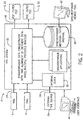
- FIG. 3 is an information flow diagram of one embodiment of a synchrophasor data management system (SDMS) 44, showing an Application System 46, a Historian System 48, a Synchrophasor Processor System (SPS) 50, and a protocol mapping system 57.
- SDMS synchrophasor data management system
- SPS Synchrophasor Processor System
- the SDMS 44 described herein may include the features of the PDC 6 of FIG. 2 along with additional features.
- the depicted SDMS 44 includes the user interface 40, the view tool 42, and the external time source 28.
- the SDMS 44 may be provided as a computing device having a chassis with a redundant power supply and one or more replaceable single board computers communicatively coupled, for example, by a data bus.
- the single board computers, or equivalents may be hot swappable.
- One additional feature of the SDMS 44 includes modularity.
- the Historian System 48 (similar to the described historian 38 of FIG. 2 ) and the Application Systems 46 (similar to the described synchrophasor applications 36 of FIG 2 ) may each be included as software components or hardware components of the single board computers.
- a first single board computer may include the SPS 50
- a second single board computer may include the Historian System 48
- a third single board computer may include the Application Systems 46, and all three boards may be disposed in the same chassis and provided with redundant power.
- the systems 46, 48, and 50 may be provided in a single processor, in multiple processor systems, in redundant processing systems, (e.g., fault tolerant computing systems), and the like.
- the Application System 46 may be used as a platform for phasor applications, and the Historian System 48 may be used to store a plurality of measurement inputs and other data.
- the Application System 46 may be used to perform functions such as scientific mathematical expressions/equations, Substation State Estimation, Synchro-Control (synchrophasor-based feedback control), Wide Area Out-of-Step measurement, and/or Oscillation Detection.
- the Application System 46 may include an operating system such as, any real time operating systems (VxWorks by Wind River), or Windows® available from Microsoft Corporation of Redmond, Washington. This may expand platform functionality by providing for custom software development using a variety of .NET tools, compilers, third-party components, and the like.
- the SDMS's 44 existing infrastructure may be used to expand and customize the platform while maintaining reliability.
- the processing block 32 of FIG. 2 may be implemented by the Synchrophasor Processor System (SPS) 50.
- SPS Synchrophasor Processor System
- Each of the systems may each be a single board computer. Comparatively, the present techniques enable faulty systems to be replaced because each feature is on its own board.
- the modularity of the SDMS 44 may facilitate upgrading in the field by adding systems, as well as improving reliability by employing redundant systems.
- Other systems may be included in the SDMS 44 such as a Data Store System configured to provide local data storage to support the Historian System 46, Redundant Power Supply Systems configured to provide high or low voltage with redundant power supplies, and an Input Power Board and Output Contacts System configured to provide an external interface with power connections and relays.
- Each of the systems may be communicatively coupled to a data bus, such as an Internal High Speed Data Exchange Bus 51.
- the techniques described herein may process, receive inputs, and send outputs using multiple protocols, such as IEEE C37.118X and IEC 61850-90-5.
- the SPS 50 may be configured to accept inputs with varying protocols and to output datasets with varying protocols.
- internal processing may be done in an agnostic format. This may be facilitated by mapping multiple communication protocols into an agnostic data structure using the protocol mappings systems 57.
- the SPS 50 includes an input protocol handler 52 configured to convert an input signal 53 protocol into the agnostic format. The agnostic format may then be used during internal processing by the SPS 50.
- the SPS 50 also includes an output protocol handler 54 configured to transmit an output signal 55 in different protocols. Accordingly, the agnostic format may be converted and transmitted.
- the output signal 55 may be stream of datasets understandable by upstream devices.
- the protocols may include IEEE C37.118X and IEC 61850-90-5, among others. By using the agnostic format, any number of new protocols may be added. A further description of mapping the protocols may be seen in FIG. 5 .
- the input protocol handler 52 maps the input signal 53 to a format (e.g., agnostic format) usable by the SPS 50
- the data is passed through an Input Stream Processor 56, a Data Processor 58, and an Output Stream Processor 59.
- the Input Stream Processor 56 may be configured to check if received data is valid.
- the Input Stream Processor 56 may, if necessary, resample the data (block 100), determine if data is lost (block 102), or determine if the time synchronization is lost (block 104). Data may need to be resampled (block 100) because even though the data measurements, phasors measurements, may be tagged with time stamps, they have been transmitted at different rates.
- a wait-time may be set, after which data may be declared lost (block 102). Finally, if the time synchronization is lost, the data may not be sufficiently accurate, which may be detected, and in certain cases overcome by using internal clocks (block 104).
- the data is passed to the Data Processor 58 which may be configured to time align the data (block 106), to structure the data (i.e. combining) (block 108), and to buffer the data (block 110).
- the Data Processor 58 may be configured to concentrate and further process the data to provide a unified data rate for real-time applications.
- the Data Processor 58 may receive a plurality of inputs from the PMUs 4 at different data rates.
- the Data Processor 58 may then transform each plurality of inputs into a time aligned output by time aligning (block 106) each plurality of inputs.
- the aligned data from multiple PMUs 4 may be combined into a single data stream (block 108).
- the data may be buffered, which may facilitate communicating data in sequence to upstream devices such as regional PDCs 18 or super PDCs 22 (block 110).
- the Output Stream Processor 59 may be configured, if necessary, to phasor filter (block 112) or down sample the data (block 114). For example, in certain cases, decimation (block 112) may be used to filter and lessen aliasing of the modulated frequencies carried by the phasor magnitudes. In addition, the sample rate of the data may be lowered (block 114) based on the upstream devices. As depicted, the data finally passes through the output protocol handler 54, is converted to the protocol requested by an upstream device, and outputted as the output signal 55.
- the techniques described herein provide for a Virtual or pseudo-PMU 60 in the SPS 50.
- the pseudo-PMU 60 may be configured to insert data from the SDMS 44 into a dataset, which may be in a PMU dataset format.
- the data may be inserted into a packetized data format that is outputted by a PMU 4.
- the SDMS 44 may be able to send data upstream by packetizing the data into the output signal 55.
- the pseudo-PMU 60 transmits the pseudo-PMU dataset 61 to the Output Stream Processor 59 to be aggregated into the output signal 55.
- PDCs 6 may be configured to receive data, which may be in the PMU dataset format, from PMUs 4.
- the upstream devices i.e. regional PDCs 18 and super PDCs 22
- the upstream devices are able to process data received in the PMU dataset format, which enables the SDMS 44 to communicate information through the existing tiered structure shown in FIG. 1 .
- the pseudo-PMU 60 may be configured to aggregate a time aligned output into the pseudo-PMU dataset 61, in which the SPS 50 is configured to transmit the pseudo-PMU dataset 61 to a second PMU 4, an external PDC 18, a super PDC 22, or a combination thereof.
- the SPS 44 containing PDC 18 functionality may enable the notification of issues and alerts such as failure of a PMU communication port, missing message limit exceeded, average communication latency exceeded, failure of authentication, or data rate output range. Diagnostic information such as average and variance of communication, input and output data rate in kbps, or the missing message rate may also be transmitted.
- the alerts and diagnostics data may not have been provided by using PMU datasets in a format compatible with a variety of devices. Any SDMS data may now be transmitted with the PMU datasets, as described herein. A further description of the usage of the pseudo-PMU 60 may be seen in FIG. 4 .
- the SDMS 44 may include PDC 6 functionality in the Input Stream Processor 56, the Data Processor 58, and the Output Stream Processor 59.
- the SDMS 44 may be viewed as a PDC 6 with the additional features (e.g., pseudo-PMU 60) described herein.
- the techniques herein may be adapted to a kit that enables the additional features to be added to an existing PDC 6, for example, by flash upgrading memory, reprogramming processors, and the like.
- each of the systems 44, 46, 48, and/or 50 described may be implemented by using computer instructions stored in a non-transitory machine-readable medium, such as the memory of a computer, server, laptop, tablet, cell phone, mobile device, or similar processing or computing device.
- the computer instructions may be configured to be executed by a processor.
- each of the systems described may be implemented in software.
- FIG. 4 is a flow chart of one embodiment of a process 62 suitable for using, for example, the pseudo-PMU 60 of the synchrophasor data management system (SDMS) 44 of FIG. 3 .
- the pseudo-PMU 60 may be used to communicate information from the SDMS 44 to devices upstream, acting as an in-band system.
- the communication process 62 may begin by checking/gathering the data that is desired to transmitted (block 64). For example, this may be checking for the presence of an issue such as average communication latency exceeded, or this could be gathering information such as a PMU latency rate. After the status is checked or information is gathered, it may be mapped into the PMU dataset format to generate the pseudo-PMU dataset 61 (block 66).
- This may include mapping the data gathered into a defined field of the PMU dataset format. For example, this may be an IEEE C37.118 dataset with no phasors (i.e., only analog and digital data fields) or an equivalent protocol.
- the Virtual PMU dataset 59 may be aggregated into the output signal 55 of the SDMS 44 (block 68). As described above in FIG. 3 , this may be done in the Output Stream Processor 59 because the data will already be in a format (i.e. PMU dataset format) useable by the Output Stream Processor 59.
- the output signal 55 will then be outputted from the SDMS 44 and transmitted to upstream devices (block 70).
- bracket 72 may be performed within the SPS 50.
- the upstream device receives the output signal 55, it may either continue monitoring the status or perform ameliorative actions (block 74).
- process 62 may be executed by the SPS 50.
- each may step may be implemented by using computer instructions stored in a non-transitory machine-readable medium, such as the memory of a computer, server, laptop, tablet, cell phone, mobile device, or similar processing or computing device.
- the computer instructions may be configured to be executed by a processor.
- the Output Protocol Handler 54 may convert the pseudo-PMU dataset 60 into the appropriate protocol for the upstream device. The protocol conversion for the output signals 55 may be seen in FIG. 5 .
- FIG. 5 is a diagram of one embodiment of a data flow 75 showing the protocol mapping system 57 in the synchrophasor data management system (SDMS) 44 of FIG. 3 .
- the SDMS 44 and more specifically the SPS 50 may be configured to accept inputs with varying protocols and to output datasets with varying protocols, which may be accomplished through mapping between multiple communication protocols, for example, to the agnostic data format.
- the present techniques enable the SDMS 44 to operate in multiple protocols.
- the SDMS 44 may accept an input signal 53 (represented by the dashed box) in a first protocol.
- the Input Protocol Handler 52 in the SDMS 44 may then use the protocol mappings 77 to convert the input signal 53 into an agnostic format 78.
- the Input Protocol Handler 52 may leave the input signal 53 in the first protocol 76, which may be also usable by the SPS 50.
- the Input Protocol Handler 52 may convert the input signal 53 to the agnostic format 78 by using data constructs, such as C-struct, an object oriented class, memory map, or an equivalent.
- the agnostic format 78 may be configured to be usable by the SPS 50 during all facets of data processing.
- the Output Protocol Handler 54 may then either use the protocol mappings 77 to convert the signal back to the first protocol 76 or to a second protocol 80 before output, so that the signal 55 may be output in the first protocol 76, in the second protocol 80, or a combination thereof.
- the SPS 50 may make similar conversions to the agnostic format 78 for processing, or in another embodiment, use the second protocol 80 during processing.
- the Output Protocol Handler 54 may output the output signal 55 in the first protocol 76 or convert the output signal 55 to the second protocol 80.
- the described protocol mapping system 57 may be used to convert between the IEEE C37.118X and IEC 61850-90-5. It should be appreciated the protocol mapping system 57 may be expanded to 3 or more protocols.
- the protocol mapping system 57 may be implemented through hardware, software, or a combination thereof.
- the mappings may be implemented by using computer instructions stored in a non-transitory machine-readable medium, such as the memory of a computer, server, laptop, tablet, cell phone, mobile device, or similar processing or computing device.
- the computer instructions may be configured to be executed by a processor.
- the PDC 6 in the monitoring system may be expanded to the SDMS 44 described herein.
- the SDMS 44 may improve reliability in the monitoring system by enabling faulty parts to be swapped out in the field and facilitating issues and/or information concerning the SDMS 44 to be transmitted upstream.
- a PDC 6 included in the SPS 50 may include a pseudo-PMU 60 and use datasets to include data additional to PMU data, such as alert and diagnostic data for the PDC 6, SPS 60, or combination thereof.
- the SDMS 44 may improve the functionality of the monitoring system by enabling features to be upgraded in the field and by enabling multiple protocols to be used.
Landscapes
- Engineering & Computer Science (AREA)
- Physics & Mathematics (AREA)
- General Physics & Mathematics (AREA)
- Databases & Information Systems (AREA)
- Theoretical Computer Science (AREA)
- Power Engineering (AREA)
- Data Mining & Analysis (AREA)
- General Engineering & Computer Science (AREA)
- Computer Networks & Wireless Communication (AREA)
- Software Systems (AREA)
- Communication Control (AREA)
- Maintenance And Management Of Digital Transmission (AREA)
- Arrangements For Transmission Of Measured Signals (AREA)
- Small-Scale Networks (AREA)
- Synchronisation In Digital Transmission Systems (AREA)
- Mobile Radio Communication Systems (AREA)
- Selective Calling Equipment (AREA)
Applications Claiming Priority (1)
| Application Number | Priority Date | Filing Date | Title |
|---|---|---|---|
| US13/709,050 US9274150B2 (en) | 2012-12-09 | 2012-12-09 | Systems for synchrophasor data management |
Publications (2)
| Publication Number | Publication Date |
|---|---|
| EP2741450A1 EP2741450A1 (en) | 2014-06-11 |
| EP2741450B1 true EP2741450B1 (en) | 2017-02-22 |
Family
ID=50000747
Family Applications (1)
| Application Number | Title | Priority Date | Filing Date |
|---|---|---|---|
| EP13196013.0A Active EP2741450B1 (en) | 2012-12-09 | 2013-12-06 | Systems for synchrophasor data management |
Country Status (8)
| Country | Link |
|---|---|
| US (2) | US9274150B2 (enExample) |
| EP (1) | EP2741450B1 (enExample) |
| JP (1) | JP6313583B2 (enExample) |
| KR (1) | KR20140074840A (enExample) |
| CN (1) | CN103872769B (enExample) |
| BR (1) | BR102013031320B1 (enExample) |
| CA (1) | CA2835300C (enExample) |
| MX (1) | MX2013014501A (enExample) |
Families Citing this family (16)
| Publication number | Priority date | Publication date | Assignee | Title |
|---|---|---|---|---|
| US10401417B2 (en) * | 2013-02-13 | 2019-09-03 | General Electric Technology Gmbh | Electrical fault location determination in a distribution system based on phasor information |
| US9778286B2 (en) * | 2013-05-21 | 2017-10-03 | The Research Foundation For The State University Of New York | Sensors for power distribution network and electrical grid monitoring system associated therewith |
| US10794939B2 (en) * | 2013-05-21 | 2020-10-06 | The Research Foundation For The State University Of New York | Sensors for power distribution network and electrical grid monitoring system associated therewith |
| CN104320303B (zh) * | 2014-10-31 | 2017-08-29 | 许继电气股份有限公司 | 一种广域保护系统通信信息流时延可靠性的评估方法 |
| CN108181508A (zh) * | 2018-01-10 | 2018-06-19 | 云南电网有限责任公司电力科学研究院 | 一种同步相量测量单元大数据快速处理的方法 |
| CN108802489B (zh) * | 2018-06-22 | 2020-08-25 | 国网陕西省电力公司电力科学研究院 | 计及新能源非频率因素出力变化的电网频率特性测试分析方法 |
| CN109361484B (zh) * | 2018-11-13 | 2020-05-26 | 上海电器科学研究所(集团)有限公司 | 一种电力系统时间同步数据的传输方法 |
| CN110365113A (zh) * | 2019-07-18 | 2019-10-22 | 国电南瑞科技股份有限公司 | 一种配网pmu动态融合配电终端功能的方法及存储介质 |
| CN110601987B (zh) * | 2019-08-22 | 2023-03-24 | 科大智能电气技术有限公司 | 一种用于相量数据集中器的数据汇集方法 |
| KR102645325B1 (ko) * | 2019-09-27 | 2024-03-11 | 한국전력공사 | 다양한 기종의 pmu로부터 동기페이저 데이터를 수집하는 장치 및 방법 |
| CN110632461B (zh) * | 2019-10-24 | 2021-10-01 | 合肥工业大学 | 同步相量数据集中器的测试方法、测试终端及测试系统 |
| CN111402568A (zh) * | 2020-04-21 | 2020-07-10 | 科大智能电气技术有限公司 | 一种用于相量数据集中器的数据通信方法 |
| CN112532472B (zh) * | 2020-11-09 | 2022-11-04 | 广东电网有限责任公司广州供电局 | 一种相量测量单元上传延时的测试方法 |
| CA3214385C (en) * | 2021-06-11 | 2025-01-21 | Iterate Studio, Inc. | DATA PIPELINE AND ACCESS TO MULTIPLE MACHINE-LEARNED MODELS |
| CN113514739B (zh) * | 2021-06-16 | 2022-09-06 | 国网吉林省电力有限公司电力科学研究院 | 一种基于iwoa-bp算法的油纸绝缘老化评估方法 |
| US12184669B2 (en) * | 2021-08-04 | 2024-12-31 | Abb Schweiz Ag | Systems and methods for malicious attack detection in phasor measurement unit data |
Family Cites Families (21)
| Publication number | Priority date | Publication date | Assignee | Title |
|---|---|---|---|---|
| JPS6037481B2 (ja) * | 1975-06-17 | 1985-08-27 | 株式会社横河電機製作所 | プロセス制御装置 |
| US5852658A (en) | 1997-06-12 | 1998-12-22 | Knight; Nelson E. | Remote meter reading system |
| JP2000059398A (ja) * | 1998-06-01 | 2000-02-25 | Tokyo Electric Power Co Inc:The | 複数の制御装置間のデ―タ伝送システム及び複数のネットワ―ク間のデ―タ伝送方法 |
| US6259173B1 (en) | 1998-06-23 | 2001-07-10 | General Electric Company | Modular protective relay with submodules |
| US6603804B1 (en) | 1999-10-01 | 2003-08-05 | Agere Systems Inc. | Upsampling filter having one-bit multipliers for multiple spread-data streams |
| JP3952676B2 (ja) * | 2000-09-12 | 2007-08-01 | 横河電機株式会社 | 多重化装置 |
| JP4217121B2 (ja) * | 2003-08-04 | 2009-01-28 | 富士通株式会社 | Ipネットワークシステムにおける音声品質評価方法および音声品質調整装置 |
| US20060259255A1 (en) | 2005-04-05 | 2006-11-16 | Anderson James C | Method of visualizing power system quantities using a configurable software visualization tool |
| US20060224336A1 (en) | 2005-04-05 | 2006-10-05 | Charles Petras | System and method for transmitting power system data over a wide area network |
| US7630863B2 (en) | 2006-09-19 | 2009-12-08 | Schweitzer Engineering Laboratories, Inc. | Apparatus, method, and system for wide-area protection and control using power system data having a time component associated therewith |
| US20080075019A1 (en) | 2006-09-27 | 2008-03-27 | Petras Charles E | Data Mapping and Sorting Method in Network Communication |
| JP4753839B2 (ja) * | 2006-11-08 | 2011-08-24 | 中国電力株式会社 | 監視制御システム |
| US20090088990A1 (en) * | 2007-09-30 | 2009-04-02 | Schweitzer Iii Edmund O | Synchronized phasor processor for a power system |
| US8405944B2 (en) * | 2007-10-09 | 2013-03-26 | Schweitzer Engineering Laboratories Inc | Distributed bus differential protection using time-stamped data |
| WO2010033839A1 (en) | 2008-09-19 | 2010-03-25 | Schweitzer Engineering Laboratories, Inc. | Distributed bus differential protection using time-stamped data |
| CN101692104A (zh) * | 2009-09-28 | 2010-04-07 | 深圳市双合电脑系统股份有限公司 | 一种电力系统电能质量监测与同步相量监测装置 |
| JP5633367B2 (ja) * | 2010-12-28 | 2014-12-03 | 富士通株式会社 | 増幅装置及び増幅方法 |
| EP2503667B1 (en) * | 2011-03-24 | 2014-03-19 | Schneider Electric GmbH | Merging Unit and Method of Operating a Merging Unit |
| US9684020B2 (en) | 2011-03-24 | 2017-06-20 | Schneider Electric Gmbh | Merging unit and method of operating a merging unit |
| US9419527B2 (en) * | 2012-03-07 | 2016-08-16 | Dialog Semiconductor Inc. | Regulation for power supply mode transition to low-load operation |
| CN102801211B (zh) * | 2012-06-13 | 2015-04-29 | 南京南瑞继保电气有限公司 | 刀片式构架的数据集中器 |
-
2012
- 2012-12-09 US US13/709,050 patent/US9274150B2/en active Active
-
2013
- 2013-11-28 CA CA2835300A patent/CA2835300C/en active Active
- 2013-12-05 BR BR102013031320-3A patent/BR102013031320B1/pt not_active IP Right Cessation
- 2013-12-06 EP EP13196013.0A patent/EP2741450B1/en active Active
- 2013-12-06 KR KR1020130151123A patent/KR20140074840A/ko not_active Ceased
- 2013-12-06 JP JP2013252587A patent/JP6313583B2/ja not_active Expired - Fee Related
- 2013-12-09 MX MX2013014501A patent/MX2013014501A/es active IP Right Grant
- 2013-12-09 CN CN201310657498.4A patent/CN103872769B/zh not_active Expired - Fee Related
-
2016
- 2016-02-29 US US15/056,867 patent/US9684700B2/en active Active
Non-Patent Citations (1)
| Title |
|---|
| None * |
Also Published As
| Publication number | Publication date |
|---|---|
| CN103872769B (zh) | 2017-12-26 |
| JP2014116946A (ja) | 2014-06-26 |
| EP2741450A1 (en) | 2014-06-11 |
| BR102013031320A2 (pt) | 2015-11-10 |
| JP6313583B2 (ja) | 2018-04-18 |
| US20140164377A1 (en) | 2014-06-12 |
| CN103872769A (zh) | 2014-06-18 |
| KR20140074840A (ko) | 2014-06-18 |
| CA2835300C (en) | 2020-12-08 |
| US9684700B2 (en) | 2017-06-20 |
| BR102013031320B1 (pt) | 2021-08-31 |
| BR102013031320A8 (pt) | 2016-06-21 |
| CA2835300A1 (en) | 2014-06-09 |
| MX2013014501A (es) | 2014-09-03 |
| US20160253396A1 (en) | 2016-09-01 |
| US9274150B2 (en) | 2016-03-01 |
Similar Documents
| Publication | Publication Date | Title |
|---|---|---|
| EP2741450B1 (en) | Systems for synchrophasor data management | |
| Liu et al. | Recent developments of FNET/GridEye—A situational awareness tool for smart grid | |
| JP5075539B2 (ja) | 広域保護制御計測システムと方法 | |
| Becejac et al. | Prime: a real‐time cyber‐physical systems testbed: from wide‐area monitoring, protection, and control prototyping to operator training and beyond | |
| CN105579992A (zh) | 选择并显示轮询和流式电力系统测量结果 | |
| US10566835B2 (en) | Detecting power outages using smartphone sensors | |
| Biswas et al. | Development of a smart grid test bed and applications in PMU and PDC testing | |
| CN102522741A (zh) | 一种应用于直流电网的同步数据采集方法 | |
| CN105403751A (zh) | 一种基于北斗的电网状态监测装置 | |
| Maheswari et al. | Wide-area measurement systems and phasor measurement units | |
| CN103698636B (zh) | 一种继电保护测试仪并行同步测试的方法 | |
| Ren | Synchrophasor measurement using substation intelligent electronic devices: algorithms and test methodology | |
| Zhu et al. | Test platform for synchrophasor based wide-area monitoring and control applications | |
| Culliss | A 3rd generation frequency disturbance recorder: A secure, low cost synchophasor measurement device | |
| Adamiak et al. | Design and implementation of a synchrophasor data concentrator | |
| CN105676061A (zh) | 广域测量系统的扰动识别功能的测试系统及方法 | |
| RU147247U1 (ru) | Устройство объединения цифровых потоков данных измерений | |
| Kezunovic et al. | Signal processing, communication, and networking requirements for synchrophasor systems | |
| CN201335885Y (zh) | 一种时间频率测试仪 | |
| Retty et al. | Development of tests and procedures for evaluating phasor data concentrators | |
| CN204945644U (zh) | 一种长输气管道分布式监测惯性授时系统 | |
| US20240152103A1 (en) | Synchronizing network reference time among power line components | |
| Thompson | The Future of Substations: Centralized Protection and Control | |
| WO2023200705A1 (en) | Continuous waveform streaming | |
| Skoff | Performance Analysis of Sampled Values-Based Protection in IEC 61850 Process Bus Networks |
Legal Events
| Date | Code | Title | Description |
|---|---|---|---|
| PUAI | Public reference made under article 153(3) epc to a published international application that has entered the european phase |
Free format text: ORIGINAL CODE: 0009012 |
|
| 17P | Request for examination filed |
Effective date: 20131206 |
|
| AK | Designated contracting states |
Kind code of ref document: A1 Designated state(s): AL AT BE BG CH CY CZ DE DK EE ES FI FR GB GR HR HU IE IS IT LI LT LU LV MC MK MT NL NO PL PT RO RS SE SI SK SM TR |
|
| AX | Request for extension of the european patent |
Extension state: BA ME |
|
| R17P | Request for examination filed (corrected) |
Effective date: 20141211 |
|
| RBV | Designated contracting states (corrected) |
Designated state(s): AL AT BE BG CH CY CZ DE DK EE ES FI FR GB GR HR HU IE IS IT LI LT LU LV MC MK MT NL NO PL PT RO RS SE SI SK SM TR |
|
| 17Q | First examination report despatched |
Effective date: 20150323 |
|
| GRAP | Despatch of communication of intention to grant a patent |
Free format text: ORIGINAL CODE: EPIDOSNIGR1 |
|
| INTG | Intention to grant announced |
Effective date: 20160722 |
|
| GRAS | Grant fee paid |
Free format text: ORIGINAL CODE: EPIDOSNIGR3 |
|
| GRAA | (expected) grant |
Free format text: ORIGINAL CODE: 0009210 |
|
| AK | Designated contracting states |
Kind code of ref document: B1 Designated state(s): AL AT BE BG CH CY CZ DE DK EE ES FI FR GB GR HR HU IE IS IT LI LT LU LV MC MK MT NL NO PL PT RO RS SE SI SK SM TR |
|
| REG | Reference to a national code |
Ref country code: GB Ref legal event code: FG4D |
|
| REG | Reference to a national code |
Ref country code: CH Ref legal event code: EP |
|
| REG | Reference to a national code |
Ref country code: AT Ref legal event code: REF Ref document number: 870038 Country of ref document: AT Kind code of ref document: T Effective date: 20170315 |
|
| REG | Reference to a national code |
Ref country code: IE Ref legal event code: FG4D |
|
| REG | Reference to a national code |
Ref country code: DE Ref legal event code: R096 Ref document number: 602013017626 Country of ref document: DE |
|
| REG | Reference to a national code |
Ref country code: LT Ref legal event code: MG4D |
|
| REG | Reference to a national code |
Ref country code: NL Ref legal event code: MP Effective date: 20170222 |
|
| REG | Reference to a national code |
Ref country code: AT Ref legal event code: MK05 Ref document number: 870038 Country of ref document: AT Kind code of ref document: T Effective date: 20170222 |
|
| PG25 | Lapsed in a contracting state [announced via postgrant information from national office to epo] |
Ref country code: LT Free format text: LAPSE BECAUSE OF FAILURE TO SUBMIT A TRANSLATION OF THE DESCRIPTION OR TO PAY THE FEE WITHIN THE PRESCRIBED TIME-LIMIT Effective date: 20170222 Ref country code: NO Free format text: LAPSE BECAUSE OF FAILURE TO SUBMIT A TRANSLATION OF THE DESCRIPTION OR TO PAY THE FEE WITHIN THE PRESCRIBED TIME-LIMIT Effective date: 20170522 Ref country code: GR Free format text: LAPSE BECAUSE OF FAILURE TO SUBMIT A TRANSLATION OF THE DESCRIPTION OR TO PAY THE FEE WITHIN THE PRESCRIBED TIME-LIMIT Effective date: 20170523 Ref country code: HR Free format text: LAPSE BECAUSE OF FAILURE TO SUBMIT A TRANSLATION OF THE DESCRIPTION OR TO PAY THE FEE WITHIN THE PRESCRIBED TIME-LIMIT Effective date: 20170222 Ref country code: FI Free format text: LAPSE BECAUSE OF FAILURE TO SUBMIT A TRANSLATION OF THE DESCRIPTION OR TO PAY THE FEE WITHIN THE PRESCRIBED TIME-LIMIT Effective date: 20170222 |
|
| PG25 | Lapsed in a contracting state [announced via postgrant information from national office to epo] |
Ref country code: LV Free format text: LAPSE BECAUSE OF FAILURE TO SUBMIT A TRANSLATION OF THE DESCRIPTION OR TO PAY THE FEE WITHIN THE PRESCRIBED TIME-LIMIT Effective date: 20170222 Ref country code: PT Free format text: LAPSE BECAUSE OF FAILURE TO SUBMIT A TRANSLATION OF THE DESCRIPTION OR TO PAY THE FEE WITHIN THE PRESCRIBED TIME-LIMIT Effective date: 20170622 Ref country code: SE Free format text: LAPSE BECAUSE OF FAILURE TO SUBMIT A TRANSLATION OF THE DESCRIPTION OR TO PAY THE FEE WITHIN THE PRESCRIBED TIME-LIMIT Effective date: 20170222 Ref country code: NL Free format text: LAPSE BECAUSE OF FAILURE TO SUBMIT A TRANSLATION OF THE DESCRIPTION OR TO PAY THE FEE WITHIN THE PRESCRIBED TIME-LIMIT Effective date: 20170222 Ref country code: ES Free format text: LAPSE BECAUSE OF FAILURE TO SUBMIT A TRANSLATION OF THE DESCRIPTION OR TO PAY THE FEE WITHIN THE PRESCRIBED TIME-LIMIT Effective date: 20170222 Ref country code: RS Free format text: LAPSE BECAUSE OF FAILURE TO SUBMIT A TRANSLATION OF THE DESCRIPTION OR TO PAY THE FEE WITHIN THE PRESCRIBED TIME-LIMIT Effective date: 20170222 Ref country code: AT Free format text: LAPSE BECAUSE OF FAILURE TO SUBMIT A TRANSLATION OF THE DESCRIPTION OR TO PAY THE FEE WITHIN THE PRESCRIBED TIME-LIMIT Effective date: 20170222 Ref country code: BG Free format text: LAPSE BECAUSE OF FAILURE TO SUBMIT A TRANSLATION OF THE DESCRIPTION OR TO PAY THE FEE WITHIN THE PRESCRIBED TIME-LIMIT Effective date: 20170522 |
|
| PG25 | Lapsed in a contracting state [announced via postgrant information from national office to epo] |
Ref country code: SK Free format text: LAPSE BECAUSE OF FAILURE TO SUBMIT A TRANSLATION OF THE DESCRIPTION OR TO PAY THE FEE WITHIN THE PRESCRIBED TIME-LIMIT Effective date: 20170222 Ref country code: CZ Free format text: LAPSE BECAUSE OF FAILURE TO SUBMIT A TRANSLATION OF THE DESCRIPTION OR TO PAY THE FEE WITHIN THE PRESCRIBED TIME-LIMIT Effective date: 20170222 Ref country code: RO Free format text: LAPSE BECAUSE OF FAILURE TO SUBMIT A TRANSLATION OF THE DESCRIPTION OR TO PAY THE FEE WITHIN THE PRESCRIBED TIME-LIMIT Effective date: 20170222 Ref country code: EE Free format text: LAPSE BECAUSE OF FAILURE TO SUBMIT A TRANSLATION OF THE DESCRIPTION OR TO PAY THE FEE WITHIN THE PRESCRIBED TIME-LIMIT Effective date: 20170222 Ref country code: IT Free format text: LAPSE BECAUSE OF FAILURE TO SUBMIT A TRANSLATION OF THE DESCRIPTION OR TO PAY THE FEE WITHIN THE PRESCRIBED TIME-LIMIT Effective date: 20170222 |
|
| REG | Reference to a national code |
Ref country code: DE Ref legal event code: R097 Ref document number: 602013017626 Country of ref document: DE |
|
| PG25 | Lapsed in a contracting state [announced via postgrant information from national office to epo] |
Ref country code: DK Free format text: LAPSE BECAUSE OF FAILURE TO SUBMIT A TRANSLATION OF THE DESCRIPTION OR TO PAY THE FEE WITHIN THE PRESCRIBED TIME-LIMIT Effective date: 20170222 Ref country code: PL Free format text: LAPSE BECAUSE OF FAILURE TO SUBMIT A TRANSLATION OF THE DESCRIPTION OR TO PAY THE FEE WITHIN THE PRESCRIBED TIME-LIMIT Effective date: 20170222 Ref country code: SM Free format text: LAPSE BECAUSE OF FAILURE TO SUBMIT A TRANSLATION OF THE DESCRIPTION OR TO PAY THE FEE WITHIN THE PRESCRIBED TIME-LIMIT Effective date: 20170222 |
|
| REG | Reference to a national code |
Ref country code: FR Ref legal event code: PLFP Year of fee payment: 5 |
|
| PLBE | No opposition filed within time limit |
Free format text: ORIGINAL CODE: 0009261 |
|
| STAA | Information on the status of an ep patent application or granted ep patent |
Free format text: STATUS: NO OPPOSITION FILED WITHIN TIME LIMIT |
|
| 26N | No opposition filed |
Effective date: 20171123 |
|
| PG25 | Lapsed in a contracting state [announced via postgrant information from national office to epo] |
Ref country code: SI Free format text: LAPSE BECAUSE OF FAILURE TO SUBMIT A TRANSLATION OF THE DESCRIPTION OR TO PAY THE FEE WITHIN THE PRESCRIBED TIME-LIMIT Effective date: 20170222 |
|
| REG | Reference to a national code |
Ref country code: CH Ref legal event code: PL |
|
| REG | Reference to a national code |
Ref country code: IE Ref legal event code: MM4A |
|
| PG25 | Lapsed in a contracting state [announced via postgrant information from national office to epo] |
Ref country code: LU Free format text: LAPSE BECAUSE OF NON-PAYMENT OF DUE FEES Effective date: 20171206 Ref country code: MT Free format text: LAPSE BECAUSE OF NON-PAYMENT OF DUE FEES Effective date: 20171206 |
|
| REG | Reference to a national code |
Ref country code: BE Ref legal event code: MM Effective date: 20171231 |
|
| PG25 | Lapsed in a contracting state [announced via postgrant information from national office to epo] |
Ref country code: IE Free format text: LAPSE BECAUSE OF NON-PAYMENT OF DUE FEES Effective date: 20171206 |
|
| PG25 | Lapsed in a contracting state [announced via postgrant information from national office to epo] |
Ref country code: LI Free format text: LAPSE BECAUSE OF NON-PAYMENT OF DUE FEES Effective date: 20171231 Ref country code: BE Free format text: LAPSE BECAUSE OF NON-PAYMENT OF DUE FEES Effective date: 20171231 Ref country code: CH Free format text: LAPSE BECAUSE OF NON-PAYMENT OF DUE FEES Effective date: 20171231 |
|
| PG25 | Lapsed in a contracting state [announced via postgrant information from national office to epo] |
Ref country code: HU Free format text: LAPSE BECAUSE OF FAILURE TO SUBMIT A TRANSLATION OF THE DESCRIPTION OR TO PAY THE FEE WITHIN THE PRESCRIBED TIME-LIMIT; INVALID AB INITIO Effective date: 20131206 Ref country code: MC Free format text: LAPSE BECAUSE OF FAILURE TO SUBMIT A TRANSLATION OF THE DESCRIPTION OR TO PAY THE FEE WITHIN THE PRESCRIBED TIME-LIMIT Effective date: 20170222 |
|
| PG25 | Lapsed in a contracting state [announced via postgrant information from national office to epo] |
Ref country code: CY Free format text: LAPSE BECAUSE OF NON-PAYMENT OF DUE FEES Effective date: 20170222 |
|
| PG25 | Lapsed in a contracting state [announced via postgrant information from national office to epo] |
Ref country code: MK Free format text: LAPSE BECAUSE OF FAILURE TO SUBMIT A TRANSLATION OF THE DESCRIPTION OR TO PAY THE FEE WITHIN THE PRESCRIBED TIME-LIMIT Effective date: 20170222 |
|
| PG25 | Lapsed in a contracting state [announced via postgrant information from national office to epo] |
Ref country code: TR Free format text: LAPSE BECAUSE OF FAILURE TO SUBMIT A TRANSLATION OF THE DESCRIPTION OR TO PAY THE FEE WITHIN THE PRESCRIBED TIME-LIMIT Effective date: 20170222 |
|
| PG25 | Lapsed in a contracting state [announced via postgrant information from national office to epo] |
Ref country code: AL Free format text: LAPSE BECAUSE OF FAILURE TO SUBMIT A TRANSLATION OF THE DESCRIPTION OR TO PAY THE FEE WITHIN THE PRESCRIBED TIME-LIMIT Effective date: 20170222 Ref country code: IS Free format text: LAPSE BECAUSE OF FAILURE TO SUBMIT A TRANSLATION OF THE DESCRIPTION OR TO PAY THE FEE WITHIN THE PRESCRIBED TIME-LIMIT Effective date: 20170622 |
|
| REG | Reference to a national code |
Ref country code: DE Ref legal event code: R079 Ref document number: 602013017626 Country of ref document: DE Free format text: PREVIOUS MAIN CLASS: H04L0012260000 Ipc: H04L0043000000 |
|
| P01 | Opt-out of the competence of the unified patent court (upc) registered |
Effective date: 20230522 |
|
| REG | Reference to a national code |
Ref country code: DE Ref legal event code: R081 Ref document number: 602013017626 Country of ref document: DE Owner name: GENERAL ELECTRIC TECHNOLOGY GMBH, CH Free format text: FORMER OWNER: GENERAL ELECTRIC COMPANY, SCHENECTADY, NY, US |
|
| REG | Reference to a national code |
Ref country code: GB Ref legal event code: 732E Free format text: REGISTERED BETWEEN 20240222 AND 20240228 |
|
| PGFP | Annual fee paid to national office [announced via postgrant information from national office to epo] |
Ref country code: DE Payment date: 20241121 Year of fee payment: 12 |
|
| PGFP | Annual fee paid to national office [announced via postgrant information from national office to epo] |
Ref country code: GB Payment date: 20241122 Year of fee payment: 12 |
|
| PGFP | Annual fee paid to national office [announced via postgrant information from national office to epo] |
Ref country code: FR Payment date: 20241121 Year of fee payment: 12 |