EP2741069A1 - Prüfstand für ein Rotorblatt oder ein Rotorblattsegment, Anordnung mit einem derartigen Prüfstand und Prüfverfahren - Google Patents
Prüfstand für ein Rotorblatt oder ein Rotorblattsegment, Anordnung mit einem derartigen Prüfstand und Prüfverfahren Download PDFInfo
- Publication number
- EP2741069A1 EP2741069A1 EP13195118.8A EP13195118A EP2741069A1 EP 2741069 A1 EP2741069 A1 EP 2741069A1 EP 13195118 A EP13195118 A EP 13195118A EP 2741069 A1 EP2741069 A1 EP 2741069A1
- Authority
- EP
- European Patent Office
- Prior art keywords
- rotor blade
- blade segment
- segment
- test
- test stand
- Prior art date
- Legal status (The legal status is an assumption and is not a legal conclusion. Google has not performed a legal analysis and makes no representation as to the accuracy of the status listed.)
- Granted
Links
- 238000012360 testing method Methods 0.000 title claims abstract description 103
- 238000010998 test method Methods 0.000 title description 4
- 230000003068 static effect Effects 0.000 claims abstract description 19
- 230000005284 excitation Effects 0.000 claims abstract description 16
- 238000000034 method Methods 0.000 claims abstract description 9
- 230000009975 flexible effect Effects 0.000 claims description 16
- 230000006835 compression Effects 0.000 claims description 5
- 238000007906 compression Methods 0.000 claims description 5
- 230000008878 coupling Effects 0.000 claims description 5
- 238000010168 coupling process Methods 0.000 claims description 5
- 238000005859 coupling reaction Methods 0.000 claims description 5
- 230000010355 oscillation Effects 0.000 abstract description 4
- 230000000638 stimulation Effects 0.000 abstract 1
- 238000005452 bending Methods 0.000 description 9
- 238000013461 design Methods 0.000 description 3
- 230000008569 process Effects 0.000 description 3
- 125000004122 cyclic group Chemical group 0.000 description 2
- 238000004088 simulation Methods 0.000 description 2
- 230000009471 action Effects 0.000 description 1
- 230000006978 adaptation Effects 0.000 description 1
- 230000008901 benefit Effects 0.000 description 1
- 238000007796 conventional method Methods 0.000 description 1
- 238000006073 displacement reaction Methods 0.000 description 1
- 230000000694 effects Effects 0.000 description 1
- 238000013507 mapping Methods 0.000 description 1
- 238000011017 operating method Methods 0.000 description 1
- 230000009467 reduction Effects 0.000 description 1
Images
Classifications
-
- G—PHYSICS
- G01—MEASURING; TESTING
- G01M—TESTING STATIC OR DYNAMIC BALANCE OF MACHINES OR STRUCTURES; TESTING OF STRUCTURES OR APPARATUS, NOT OTHERWISE PROVIDED FOR
- G01M5/00—Investigating the elasticity of structures, e.g. deflection of bridges or air-craft wings
- G01M5/0016—Investigating the elasticity of structures, e.g. deflection of bridges or air-craft wings of aircraft wings or blades
-
- G—PHYSICS
- G01—MEASURING; TESTING
- G01M—TESTING STATIC OR DYNAMIC BALANCE OF MACHINES OR STRUCTURES; TESTING OF STRUCTURES OR APPARATUS, NOT OTHERWISE PROVIDED FOR
- G01M5/00—Investigating the elasticity of structures, e.g. deflection of bridges or air-craft wings
- G01M5/0041—Investigating the elasticity of structures, e.g. deflection of bridges or air-craft wings by determining deflection or stress
- G01M5/005—Investigating the elasticity of structures, e.g. deflection of bridges or air-craft wings by determining deflection or stress by means of external apparatus, e.g. test benches or portable test systems
- G01M5/0058—Investigating the elasticity of structures, e.g. deflection of bridges or air-craft wings by determining deflection or stress by means of external apparatus, e.g. test benches or portable test systems of elongated objects, e.g. pipes, masts, towers or railways
-
- G—PHYSICS
- G01—MEASURING; TESTING
- G01M—TESTING STATIC OR DYNAMIC BALANCE OF MACHINES OR STRUCTURES; TESTING OF STRUCTURES OR APPARATUS, NOT OTHERWISE PROVIDED FOR
- G01M5/00—Investigating the elasticity of structures, e.g. deflection of bridges or air-craft wings
- G01M5/0066—Investigating the elasticity of structures, e.g. deflection of bridges or air-craft wings by exciting or detecting vibration or acceleration
Definitions
- the invention relates to a test stand for a rotor blade or a rotor blade segment, in particular a rotor blade or a rotor blade segment for a wind turbine, according to the preamble of claim 1.
- the invention further relates to an arrangement with such a test bed and a rotor blade or a rotor blade segment and a method for operating the test bench.
- WO 2008/145727 A1 a test stand of the type mentioned is known.
- the well-known test bench is used for vibration testing of rotor blades, whereby the rotor blade is mounted on a foundation of the test bench in a horizontal position. Distanced from the foundation an excitation unit is provided, which is attached to the bottom of the test bench and transmits via a lever an excitation vibration on the rotor blade.
- the excitation unit is designed in the form of a hydraulic cylinder.
- the lever arrangement between the hydraulic cylinder and the rotor blade reduces the oscillating mass. Concretely, an upward movement of the hydraulic cylinder means a downward movement of the rotor blade. Due to the lever length, the deflection of the rotor blade is limited under the action of the hydraulic cylinder.
- the known test bench takes into account the operating loads occurring in real operation, which act on the rotor blade, only inadequate. In real operation created by the flow of the rotor blades a buoyancy force that is not simulated with the known test.
- the object of the invention is to provide a test stand for a rotor blade or a rotor blade segment, which reflects the operating loads occurring in real operation well and in particular takes into account buoyancy forces. Furthermore, the object of the invention is to provide an arrangement with such a test stand and a method for operating such a test stand.
- the object is achieved by a test stand for a rotor blade or a rotor blade segment, in particular a rotor blade or a rotor blade segment for a wind turbine, wherein the test stand has at least one support structure, to which an axial end of the rotor blade or the rotor blade segment can be fastened, and wherein at least an excitation unit is provided which can be connected to excite a vibration of the rotor blade or the rotor blade segment with the rotor blade or the rotor blade segment.
- a load means is attached.
- the load means can be connected to the rotor blade or the rotor blade segment for the test operation such that the rotor blade or the rotor blade segment can be acted upon by a static biasing force whose force direction has at least one component which runs perpendicular to the rotor blade or rotor blade segment.
- the load means as a component of the test rig improves the realism of the test.
- a static biasing force can be applied to the rotor blade or the rotor blade segment, so that, for example, the buoyancy force occurring in real operation can be simulated.
- the test stand according to the invention thus enables a relatively accurate mapping of the static operating loads occurring in real operation.
- the pivot point can be stationary in the test bench according to the invention only in test mode. Between individual test cycles the articulation point can be variable. In other words, the articulation point can be moved or offset when the test stand is not in operation. In operation, the pivot point remains stationary, in particular to apply a uniform repeatable load on the specimen.
- a plurality of load means are provided, which are attached to spaced-apart fixing points such that the rotor blade or the rotor blade segment with the same or different biasing force can be acted upon.
- different introduction points for the static force introduction can be defined over the entire length of the rotor blade. This further increases the realism of the rotor blade test. It can be provided that different biasing forces are exerted on the rotor blade at different load means. Thus, for example, occurring in real operation static bending shape of the rotor blade can be modeled. Overall, the adjustment options of the test bench are improved in this way and increases the possibilities for varying the test.
- the load means may be connectable by a flexible traction means, in particular a rope or a chain and / or by a rigid tension / pressure means, in particular a coupling rod, with the rotor blade or the rotor blade segment.
- a flexible traction device has the advantage that the direction of force can be varied easily and quickly.
- the flexible traction means may be guided over a deflection point, wherein the position of the deflection point is variable.
- a biasing force can also be applied to the rotor blade, which at least partially has a horizontal force component.
- the flexible traction means may be guided obliquely away from the rotor blade or from the rotor blade segment to the fixing point.
- the use of a rigid traction / compression means also allows the direct introduction of compressive loads in the rotor blade or the rotor blade segment.
- the load means may be formed by a motor, in particular an electrically driven motor.
- the biasing force can be easily adjusted, for example, depending on the rotor blade or rotor blade segment to be tested. Further, the biasing force can be varied by means of the motor in the test mode, for example, to map different operating load curves.
- a spring element can be arranged between the load means and the rotor blade or the rotor blade segment, so that the rotor blade or the rotor blade segment can be acted upon by the spring element with a spring force to influence the vibration behavior.
- the static biasing force acting on the rotor blade or the rotor blade segment can be superimposed with a dynamic oscillation of the rotor blade or rotor blade segment, wherein the spring elements additionally increase the frequency of the self-oscillation of the rotor blade or rotor blade segment. This shortens the test period required for the vibration test.
- the vibration test of a rotor blade or rotor blade segment can be performed in a relatively short period of time with the test stand according to the invention, while at the same time the operating loads occurring in real operation are taken into account.
- a boom is provided between the load means and the rotor blade segment, which is connected directly to the rotor blade segment and connected to the load means such that the rotor blade segment can be acted upon by a static biasing force, the force direction comprises at least one component, which runs parallel to the rotor blade segment.
- the test stand according to the invention is not only suitable for testing complete rotor blades, but also makes it possible to test rotor blade segments, for example a rotor blade segment, which is formed from a part of a complete rotor blade including the rotor blade root. In this way, the length of the object to be tested is shortened, whereby at the same time the natural vibration frequency is increased.
- the boom connected to the load means makes it possible to simulate the forces acting on the complete rotor blade in the rotor blade segment, in particular to simulate the effects of the operating loads acting on the rotor blade tip on the basis of a rotor blade segment.
- This ensures a realistic test, despite the fact that the rotor blade is not tested in its entirety but only in segments.
- a static biasing force is applied to the rotor blade segment, which has at least one component which extends parallel to the rotor blade segment. In this way, in particular, acting on the rotor blade root centrifugal force to be emulated.
- the invention is based on the idea to provide an arrangement with a previously described test stand and a rotor blade or a rotor blade segment, in particular for a wind turbine, wherein the rotor blade or the rotor blade segment attached to the support structure and connected to the load means.
- a further subsidiary aspect relates to a method for operating the above-described test stand or the arrangement described above, wherein the biasing force of the load means is adjusted such that the operating loads acting on the rotor blade or the rotor blade segment in real operation are modeled.
- the test stand according to the invention is used in particular for the vibration testing of rotor blades 10 for use.
- the test stand is suitable for testing rotor blades 10 of wind power plants.
- the rotor blades 10 can be tested as a whole or in segments.
- the test stand has a support structure 11, which may be formed as upstanding from a bottom 15 or fixed to the ground 15 foundation.
- the stable support structure 11 has a fixing device, not shown, for the rotor blade 10.
- the rotor blade 10 is connected to the foundation 11 in such a way that the rotor blade 10 extends substantially horizontally. This does not exclude that the rotor blade 10 at least partially from the horizontal.
- the statement according to which the support structure 11 is suitable for essentially horizontal attachment of the rotor blade 10 is only intended to clarify that the rotor blade 10 is arranged lengthwise freely above the bottom 15 during the test procedure ,
- the rotor blade 10 is attached to a side surface of the support structure 11 like a cantilever beam.
- the rotor blade 10 is excited to oscillate in order to simulate the cyclic loads occurring in real operation.
- the excitation of the vibrations is preferably carried out via an excitation unit, which in the embodiment according to Fig. 1 is designed as a winch 22.
- the excitation unit is attached as unbalance exciter 12 on the rotor blade 10.
- the winch 22 generally forms a load means 31 for applying a static biasing force to the rotor blade 10.
- the winch 22, which may have an electric drive, can apply a bias to a flexible traction means 17 which is connected to the rotor blade 10.
- the flexible traction means 17 or rope, in particular wire rope, transmits the biasing force applied by the cable winch 22 to the rotor blade 10 so that it is loaded statically perpendicular to its longitudinal axis.
- a rigid pressure / traction means can be used, for example, a coupling rod. In this way, pressure loads on the rotor blade 10 can be transmitted.
- the entire rotor blade 10 can be subjected to a static load during the testing process, whereby, for example, the buoyancy force or, in general, the static operating loads occurring during operation can be simulated by different biases on different brackets 16 , This improves a realistic simulation or test, in which the static and cyclic loads are superimposed.
- the traction means 17 or rope is deflected at a deflection roller 19 and guided horizontally to the winch 22, so that the test stand has a compact design.
- the traction means 17 or rope is deflected at a deflection roller 19 and guided horizontally to the winch 22, so that the test stand has a compact design.
- the traction means 17 or rope is deflected at a deflection roller 19 and guided horizontally to the winch 22, so that the test stand has a compact design.
- a plurality of such traction means 17 and load means 31 along the rotor blade 10 may be arranged.
- the spring element 13 comprises a cylinder 24, in which a piston 23 is guided.
- a compression spring 13a extends between the piston 23 and a cylinder bottom 24a.
- the piston 23 has a piston rod 23 a, which is coupled to the traction means 17 or rope.
- the rope passes over the pulley 22 which is fixedly connected to the bottom 15.
- the fixed connection between the pulley 22 and the bottom 15 forms a pivot point 14 of the traction means 17th
- the cylinder 24 is also coupled to a cable 17, which is guided via a deflection roller 19 to a holder 16.
- the holder 16 can be connected to a rotor blade 10 or connected to the rotor blade 10 during the test procedure.
- the spring element 13 or the spring assembly comprising the compression spring 13a, the cylinder 24 and the piston 23, is arranged substantially horizontally between the pulley 22 and the guide roller 19. In this way it is achieved that the support structure 11 may have a relatively small height, without affecting the Federhubweg of the spring element 13.
- the spring element 13 is coupled to a single holder 16.
- holders 16 are connected via a load harness 18 with a single spring element 13. This is in Fig. 1 indicated in the region of the blade tip 10b of the rotor blade 10.
- the rotor blade 10 In order to reduce the time required for a test procedure, it is provided to couple the rotor blade 10 to the bottom 15 via at least one spring element 13. As a result, the rigidity is increased, so that the natural frequency is increased. Thus, a predefined number of oscillations can be traversed in a relatively shorter test period.
- the interposition of the spring element 13 between the rotor blade 10 and the bottom 15 can be done in different ways.
- the proposed test bench allows the setting of individual, in particular predetermined, target bending lines.
- the shape of the bending lines is determined by the spring stiffness of the spring elements 13.
- the spring stiffness of the individual spring elements 13 can be adjusted differently.
- the spring stiffnesses of spring elements 13 can be set differently, which engage at points on the rotor blade 10, which are arranged adjacent to the span of the rotor blade 10.
- the setting of a predetermined bending line can be made possible by a test stand for a rotor blade 10 or a rotor blade segment 20, in particular a rotor blade 10 or a rotor blade segment 20 for a wind turbine, with a support structure 15 and at least one excitation unit, wherein on the support structure 15 an axial End of the rotor blade 10 or the rotor blade segment 20 is fastened and the excitation unit for exciting a vibration of the rotor blade 10 or the rotor blade segment 20 with the rotor blade 10 or the rotor blade segment 20 is connectable, wherein a plurality of longitudinally spaced apart in the longitudinal direction of the rotor blade 10 or rotor blade segment 20 spaced spring elements 13th are provided, which are each arranged between a fixed pivot point 14 and the rotor blade 10 or the rotor blade segment 20 and have different spring stiffnesses such that a predetermined target bending line is adjustable.
- a reduction of the test time can be achieved further by using instead of an entire rotor blade 10 a rotor blade segment 20, ie a rotor blade 10 shortened around the blade tip 10b, for the test.
- a rotor blade segment 20 is also referred to as a wing stump 20a. Due to the smaller compared to the entire rotor blade 10 length rotor blade segment 20 increases the natural frequency and consequently the test speed.
- the forces acting on the wing tip 10b when testing a complete rotor blade 10 can be simulated by design measures of the test stand.
- Fig. 2 shows such a variant of the test bed, in which instead of a complete rotor blade 10, a rotor blade segment 20 is attached to the support structure 11.
- the rotor blade segment 20 comprises a part of the rotor blade wing and the rotor blade root 10a.
- the rotor blade segment 20 is coupled with load harness 18. Between the load harnesses 18 and one articulation point 14 at the bottom 15, a spring element 13 is arranged in each case.
- a boom 21 is attached at the wing stump 20a of the rotor blade segment 20, a boom 21 is attached.
- the boom 21 extends substantially perpendicular to the rotor blade segment 20 and is connected to a flexible traction means 17, in particular a rope.
- the connection between the boom 21 and the traction means 17 or rope takes place indirectly via a spring element 13.
- the rope engages at an angle to the boom 21.
- the excitation of the oscillation takes place in accordance with the exemplary embodiment Fig. 2 by an unbalance exciter 12, which is mounted on the height of the boom 21 on the rotor blade segment 20. Another arrangement of the unbalance exciter 12 is possible. Furthermore, instead of an unbalance exciter 12 another excitation unit can be used. Corresponding excitation units or actuators are known to the person skilled in the art.
- a plurality of holders 16 can be arranged along the rotor blade 10. Between the rotor blade root 10a and the rotor blade tip 10b, holders 16 are preferably arranged at regular intervals. The holders 16 are connected to the spring elements 13, wherein in each case a single holder 16 may be coupled to a single spring element 13. Alternatively, two holders 16 may be coupled to a single spring element 13, for example via a load harness 20.
- a single holder is connected to a single spring element 13, wherein a plurality of combinations of holder 16 and spring element 13 are connected to a single pivot point 14.
- the individual combinations of holder 16 and spring element 13 are combined with a load harness 18 and connected for example via a rigid pressure / traction means 18 or a coupling rod or a flexible traction means 17 or a rope to the articulation point 14.
- the spring elements 13, which are arranged along the rotor blade 10 each have lower spring stiffnesses with increasing distance to the foundation 11.
- the spring elements 13 may thus comprise different spring stiffnesses.
- the spring element 13, which is closest to the rotor blade tip 10b, preferably has the lowest spring stiffness.
- the spring element which is arranged closest to the rotor root 10a preferably has the highest spring rigidity.
- the static biasing force along the rotor blade or the rotor blade segment can be varied.
- a plurality of load means 31, in particular winches 22, can be arranged along the rotor blade, which apply different prestressing forces to the rotor blade 10 or the rotor blade segment 20.
- the amount of prestressing forces may increase, for example, towards the rotor blade tip 10b or the wing stump 20a. This reflects the static loads actually occurring due to buoyancy forces, which act on the flow of the rotor blade 10 in operation, well again.
- the test stand is basically suitable for testing all types of rotor blades 10 or similar, wing-like elements or generally elongated, flexurally flexible components.
- aircraft wings or wings could also be subjected to a vibration test with the test stand according to the invention become.
- Particularly preferred is the use of the test rig for testing rotor blades 10 for wind turbines, in particular rotor blades 10 of different length and design.
- the test stand can be used flexibly overall and also includes different load harnesses 18 or holders 16, which are adapted for different rotor blade cross sections.
Landscapes
- Engineering & Computer Science (AREA)
- Aviation & Aerospace Engineering (AREA)
- Physics & Mathematics (AREA)
- General Physics & Mathematics (AREA)
- Wind Motors (AREA)
- Investigating Strength Of Materials By Application Of Mechanical Stress (AREA)
- Testing Of Devices, Machine Parts, Or Other Structures Thereof (AREA)
Abstract
Description
- Die Erfindung betrifft einen Prüfstand für ein Rotorblatt oder ein Rotorblattsegment, insbesondere ein Rotorblatt oder ein Rotorblattsegment für eine Windkraftanlage, nach dem Oberbegriff des Patentanspruchs 1. Die Erfindung befasst sich ferner mit einer Anordnung mit einem derartigen Prüfstand und einem Rotorblatt oder einem Rotorblattsegment sowie einem Verfahren zum Betreiben des Prüfstands. Aus
WO 2008/145727 A1 ist ein Prüfstand der eingangs genannten Art bekannt. - Der bekannte Prüfstand kommt zur Schwingungsprüfung von Rotorblättern zum Einsatz, wobei das Rotorblatt an einem Fundament des Prüfstands in waagrechter Lage montiert wird. Beabstandet vom Fundament ist ein Anregungsaggregat vorgesehen, das am Boden des Prüfstands befestigt ist und über einen Hebel eine Anregungsschwingung auf das Rotorblatt überträgt. Das Anregungsaggregat ist dazu in Form eines Hydraulikzylinders ausgebildet. Durch die Hebelanordnung zwischen dem Hydraulikzylinder und dem Rotorblatt wird die schwingende Masse reduziert. Konkret bedeutet eine Aufwärtsbewegung des Hydraulikzylinders eine Abwärtsbewegung des Rotorblatts. Durch die Hebellänge ist die Auslenkung des Rotorblatts unter Einwirkung des Hydraulikzylinders begrenzt. Zudem berücksichtigt der bekannte Prüfstand die im Realbetrieb auftretenden Betriebslasten, die auf das Rotorblatt wirken, nur unzureichend. Im Realbetrieb entsteht durch die Anströmung der Rotorblätter eine Auftriebskraft, die mit dem bekannten Prüfstand nicht simulierbar ist.
- Die Aufgabe der Erfindung besteht darin, einen Prüfstand für ein Rotorblatt oder ein Rotorblattsegment anzugeben, der die im realen Betrieb auftretenden Betriebslasten gut wiedergibt und insbesondere Auftriebskräfte berücksichtigt. Ferner besteht die Aufgabe der Erfindung darin, eine Anordnung mit einem derartigen Prüfstand sowie ein Verfahren zum Betreiben eines derartigen Prüfstands anzugeben.
- Erfindungsgemäß wird diese Aufgabe im Hinblick auf den Prüfstand durch den Gegenstand des Patentanspruchs 1, im Hinblick auf die Anordnung durch den Gegenstand des Patentanspruchs 7, und im Hinblick auf das Betriebsverfahren durch den Gegenstand des Patentanspruchs 8 gelöst.
- Insbesondere wird die Aufgabe durch einen Prüfstand für ein Rotorblatt oder ein Rotorblattsegment, insbesondere ein Rotorblatt oder ein Rotorblattsegment für eine Windkraftanlage, gelöst, wobei der Prüfstand wenigstens eine Tragstruktur aufweist, an der ein axiales Ende des Rotorblatts oder des Rotorblattsegments befestigbar ist, und wobei wenigstens ein Anregungsaggregat vorgesehen ist, das zur Anregung einer Schwingung des Rotorblatts oder des Rotorblattsegments mit dem Rotorblatt oder dem Rotorblattsegment verbindbar ist. An einer ortsfesten Anlenkstelle ist ein Lastmittel befestigt. Das Lastmittel ist mit dem Rotorblatt oder dem Rotorblattsegment für den Prüfbetrieb verbindbar derart, dass das Rotorblatt oder das Rotorblattsegment mit einer statischen Vorspannkraft beaufschlagbar ist, deren Kraftrichtung wenigstens eine Komponente aufweist, die senkrecht zum Rotorblatt oder Rotorblattsegment verläuft.
- Durch das Lastmittel als Komponente des Prüfstands wird die Realitätsnähe der Prüfung verbessert. Insbesondere kann mit dem Lastmittel eine statische Vorspannkraft auf das Rotorblatt oder das Rotorblattsegment aufgebracht werden, so dass beispielsweise die im Realbetrieb auftretende Auftriebskraft simuliert werden kann. Somit können mit dem erfindungsgemäßen Prüfstand insgesamt realitätsnähere Prüfungen vorgenommen werden, als dies bei den aus dem Stand der Technik bekannten Prüfständen der Fall ist. Der erfindungsgemäße Prüfstand ermöglicht also eine relativ genaue Abbildung der im Realbetrieb auftretenden statischen Betriebslasten.
- Es wird darauf hingewiesen, dass die Anlenkstelle bei dem erfindungsgemäßen Prüfstand nur im Prüfbetrieb ortsfest sein kann. Zwischen einzelnen Prüfzyklen kann die Anlenkstelle variabel sein. Mit anderen Worten kann die Anlenkstelle verschoben bzw. versetzt werden, wenn der Prüfstand nicht in Betrieb ist. Im Betrieb bleibt die Anlenkstelle ortsfest, insbesondere um eine gleichmäßig wiederholbare Belastung auf den Prüfkörper aufzubringen.
- Bei einer bevorzugten Ausführungsform des erfindungsgemäßen Prüfstands sind mehrere Lastmittel vorgesehen, die an voneinander beabstandet angeordneten Fixierstellen befestigt sind derart, dass das Rotorblatt oder das Rotorblattsegment mit gleicher oder unterschiedlicher Vorspannkraft beaufschlagbar ist. Durch eine Vielzahl von Lastmitteln können über die gesamte Länge des Rotorblatts unterschiedliche Einleitungspunkte für die statische Krafteinleitung festgelegt werden. Dies erhöht weiter die Realitätsnähe der Rotorblattprüfung. Dabei kann vorgesehen sein, dass an unterschiedlichen Lastmitteln unterschiedliche Vorspannkräfte auf das Rotorblatt ausgeübt werden. Somit kann beispielsweise die im realen Betrieb auftretende statische Biegeform des Rotorblatts nachgebildet werden. Insgesamt werden die Einstellmöglichkeiten des Prüfstands auf diese Weise verbessert und die Variationsmöglichkeiten für die Prüfung erhöht.
- Das Lastmittel kann durch ein flexibles Zugmittel, insbesondere ein Seil oder eine Kette und/oder durch ein starres Zug-/Druckmittel, insbesondere eine Koppelstange, mit dem Rotorblatt oder dem Rotorblattsegment verbindbar sein. Die Verwendung eines flexiblen Zugmittels hat den Vorteil, dass die Kraftrichtung einfach und schnell variierbar ist. Beispielsweise kann das flexible Zugmittel über eine Umlenkstelle geführt sein, wobei die Position der Umlenkstelle variabel ist. Somit kann auf das Rotorblatt auch eine Vorspannkraft aufgebracht werden, die zumindest teilweise eine waagrechte Kraftkomponente aufweist. Beispielsweise kann das flexible Zugmittel schräg vom Rotorblatt oder vom Rotorblattsegment weg zur Fixierstelle geführt sein. Die Verwendung eines starren Zug-/Druckmittels ermöglicht auch das direkte Einbringen von Drucklasten in das Rotorblatt oder das Rotorblattsegment.
- Das Lastmittel kann durch einen Motor, insbesondere einen elektrisch angetriebenen Motor, gebildet sein. Auf diese Weise kann die Vorspannkraft einfach eingestellt werden, beispielsweise in Abhängigkeit des zu prüfenden Rotorblatts bzw. Rotorblattsegments. Ferner kann die Vorspannkraft mit Hilfe des Motors im Prüfbetrieb variiert werden, beispielsweise um unterschiedliche Betriebslastverläufe abzubilden.
- Bei einer weiteren bevorzugten Ausführungsform des erfindungsgemäßen Prüfstands ist zwischen dem Lastmittel und dem Rotorblatt oder dem Rotorblattsegment ein Federelement anordenbar, so dass das Rotorblatt oder das Rotorblattsegment zur Beeinflussung des Schwingungsverhaltens durch das Federelement mit einer Federkraft beaufschlagbar ist. Somit kann die statische Vorspannkraft, die auf das Rotorblatt oder das Rotorblattsegment wirkt, mit einer dynamischen Schwingung des Rotorblatts oder Rotorblattsegments überlagert werden, wobei durch die Federelemente zusätzlich die Frequenz der Eigenschwingung des Rotorblatts oder Rotorblattsegments erhöht wird. Das verkürzt den für die Schwingungsprüfung erforderlichen Prüfzeitraum. Somit kann mit dem erfindungsgemäßen Prüfstand die Schwingungsprüfung eines Rotorblatts oder Rotorblattsegments in einem relativ kurzen Zeitraum durchgeführt werden, wobei gleichzeitig die im Realbetrieb auftretenden Betriebslasten Berücksichtigung finden.
- Bei einer weiteren bevorzugten Ausgestaltung des erfindungsgemäßen Prüfstands ist zwischen dem Lastmittel und dem Rotorblattsegment ein Ausleger vorgesehen, der direkt mit dem Rotorblattsegment verbindbar und mit dem Lastmittel verbunden ist derart, dass das Rotorblattsegment mit einer statischen Vorspannkraft beaufschlagbar ist, deren Kraftrichtung wenigstens eine Komponente aufweist, die parallel zum Rotorblattsegment verläuft. Im Allgemeinen eignet sich der erfindungsgemäße Prüfstand nicht nur zur Prüfung von vollständigen Rotorblättern, sondern ermöglicht auch die Prüfung von Rotorblattsegmenten, beispielsweise eines Rotorblattsegments, das aus einem Teil eines vollständigen Rotorblatts einschließlich der Rotorblattwurzel gebildet ist. Auf diese Weise wird die Länge des zu prüfenden Gegenstands verkürzt, wodurch gleichzeitig die Eigenschwingungsfrequenz erhöht wird. Der erforderliche Prüfzeitraum wird somit reduziert. Gleichzeitig wird durch den mit dem Lastmittel verbundenen Ausleger ermöglicht, die auf das vollständige Rotorblatt wirkenden Kräfte im Rotorblattsegment nachzubilden, insbesondere die Auswirkungen der auf die Rotorblattspitze wirkenden Betriebslasten anhand eines Rotorblattsegments zu simulieren. Dies stellt eine realitätsnahe Prüfung sicher, trotzdem das Rotorblatt nicht im Gesamten sondern lediglich segmentweise einer Prüfung unterzogen wird. Dazu ist konkret vorgesehen, dass eine statische Vorspannkraft auf das Rotorblattsegment aufgebracht wird, die zumindest eine Komponente aufweist, die parallel zum Rotorblattsegment verläuft. Auf diese Weise soll insbesondere die auf die Rotorblattwurzel wirkende Zentrifugalkraft nachgebildet werden.
- Gemäß einem nebengeordneten Aspekt beruht die Erfindung auf dem Gedanken, eine Anordnung mit einem zuvor beschriebenen Prüfstand und einem Rotorblatt oder einem Rotorblattsegment, insbesondere für eine Windkraftanlage, anzugeben, wobei das Rotorblatt oder das Rotorblattsegment an der Tragstruktur befestigt und mit dem Lastmittel verbunden ist.
- Ein weiterer nebengeordneter Aspekt betrifft ein Verfahren zum Betreiben des zuvor beschriebenen Prüfstands oder der zuvor beschriebenen Anordnung, wobei die Vorspannkraft des Lastmittels derart eingestellt wird, dass die im realen Betrieb auf das Rotorblatt oder das Rotorblattsegment wirkenden Betriebslasten nachgebildet werden.
- Die Erfindung wird im Folgenden anhand von Ausführungsbeispielen unter Bezugnahme auf die beigefügten, schematischen Zeichnungen näher erläutert. Darin zeigen
- Fig. 1
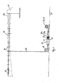
- eine Seitenansicht eines erfindungsgemäßen Prüfstands nach einem bevorzugten Ausführungsbeispiel, wobei das Lastmittel über ein umgelenktes Zugmittel mit dem Rotorblatt verbunden ist; und
- Fig. 2
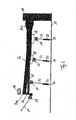
- eine Seitenansicht eines erfindungsgemäßen Prüfstands nach einem weiteren bevorzugten Ausführungsbeispiel, wobei das Lastmittel über ein Zugmittel und einen Ausleger mit einem Rotorblattsegment verbunden ist.
- Der erfindungsgemäße Prüfstand gelangt insbesondere zur Schwingungsprüfung von Rotorblättern 10 zur Anwendung. Im Besonderen eignet sich der Prüfstand für die Prüfung von Rotorblättern 10 von Windkraftanlagen. Dabei können die Rotorblätter 10 als Ganzes oder segmentweise geprüft werden.
- Der Prüfstand weist eine Tragstruktur 11 auf, die als von einem Boden 15 aufragendes bzw. am Boden 15 befestigtes Fundament ausgebildet sein kann. Die stabile Tragstruktur 11 weist eine nicht dargestellte Befestigungsvorrichtung für das Rotorblatt 10 auf. Das Rotorblatt 10 wird derart mit dem Fundament 11 verbunden, dass sich das Rotorblatt 10 im Wesentlichen horizontal erstreckt. Das schließt nicht aus, dass sich das Rotorblatt 10 zumindest teilweise aus der Horizontalen erhebt, beispielsweise aufgrund der geometrischen Form des Rotorblatts 10. Die Angabe, wonach die Tragstruktur 11 zur im Wesentlichen horizontalen Befestigung des Rotorblatts 10 geeignet ist, soll lediglich verdeutlichen, dass das Rotorblatt 10 während des Prüfvorgangs der Länge nach frei über dem Boden 15 angeordnet ist. Das Rotorblatt 10 ist wie ein Kragträger an einer Seitenfläche der Tragstruktur 11 befestigt.
- Während des Prüfvorgangs wird das Rotorblatt 10 zu Schwingungen angeregt, um die im Realbetrieb auftretenden zyklischen Lasten zu simulieren. Die Anregung der Schwingungen erfolgt vorzugsweise über ein Anregungsaggregat, das bei dem Ausführungsbeispiel gemäß
Fig. 1 als Seilwinde 22 ausgebildet ist. Alternativ kann vorgesehen sein, dass das Anregungsaggregat als Unwuchterreger 12 auf dem Rotorblatt 10 befestigt ist. - Die Seilwinde 22 bildet im Allgemeinen ein Lastmittel 31 zum Aufbringen einer statischen Vorspannkraft auf das Rotorblatt 10. Die Seilwinde 22, die einen elektrischen Antrieb aufweisen kann, kann eine Vorspannung auf ein flexibles Zugmittel 17 aufbringen, das mit dem Rotorblatt 10 verbunden ist. Das flexible Zugmittel 17 bzw. Seil, insbesondere Drahtseil, überträgt die von der Seilwinde 22 aufgebrachte Vorspannkraft auf das Rotorblatt 10, so dass dieses senkrecht zu seiner Längsachse statisch belastet wird. Anstelle eines flexiblen Zugmittels 17 kann auch ein starres Druck-/Zugmittel Anwendung finden, beispielsweise eine Koppelstange. Auf diese Weise können auch Druckbelastungen auf das Rotorblatt 10 übertragen werden.
- Im Allgemeinen wird mit der als Lastmittel 31 eingesetzten Seilwinde 22 erreicht, dass das gesamte Rotorblatt 10 während des Prüfvorgangs einer statischen Last ausgesetzt werden kann, wobei durch unterschiedliche Vorspannungen an verschiedenen Haltern 16 beispielsweise die im Betrieb auftretende Auftriebskraft bzw. allgemein die statischen Betriebslasten simulierbar sind. Dies verbessert eine realitätsnahe Simulation bzw. Prüfung, bei der die statischen und zyklischen Lasten überlagert werden.
- Bei dem Prüfstand gemäß
Fig. 1 ist das Zugmittel 17 bzw. Seil an einer Umlenkrolle 19 umgelenkt und horizontal zur Seilwinde 22 geführt, so dass der Prüfstand eine kompakte Bauweise aufweist. Aus Gründen der Übersichtlichkeit ist lediglich ein einziges Zugmittel 17 dargestellt. Tatsächlich können mehrere derartiger Zugmittel 17 sowie Lastmittel 31 entlang des Rotorblatts 10 angeordnet sein. - Zwischen dem Rotorblatt 10 und der Seilwinde 22, insbesondere zwischen der Umlenkrolle 19 und der Seilwinde 22, ist ein Federelement 13 angeordnet. Das Federelement 13 umfasst einen Zylinder 24, in dem ein Kolben 23 geführt ist. Eine Druckfeder 13a erstreckt sich zwischen dem Kolben 23 und einem Zylinderboden 24a. Der Kolben 23 weist eine Kolbenstange 23a auf, die mit dem Zugmittel 17 bzw. Seil gekoppelt ist. Das Seil verläuft über die Seilrolle 22, die fest mit dem Boden 15 verbunden ist. Die feste Verbindung zwischen der Seilrolle 22 und dem Boden 15 bildet eine Anlenkstelle 14 des Zugmittels 17.
- Der Zylinder 24 ist ebenfalls mit einem Seil 17 gekoppelt, das über eine Umlenkrolle 19 zu einem Halter 16 geführt ist. Der Halter 16 ist mit einem Rotorblatt 10 verbindbar bzw. während des Prüfvorgangs mit dem Rotorblatt 10 verbunden. Das Federelement 13 bzw. das Federpaket umfassend die Druckfeder 13a, den Zylinder 24 und den Kolben 23, ist im Wesentlichen horizontal zwischen der Seilrolle 22 und der Umlenkrolle 19 angeordnet. Auf diese Weise wird erreicht, dass die Tragstruktur 11 eine relativ geringe Höhe aufweisen kann, ohne den Federhubweg des Federelements 13 zu beeinträchtigen.
- Bei dem Ausführungsbeispiel gemäß
Fig. 1 ist das Federelement 13 mit einem einzelnen Halter 16 gekoppelt. Alternativ kann vorgesehen sein, dass jeweils zwei oder mehrere, insbesondere 3 oder 4, Halter 16 über ein Lastgeschirr 18 mit einem einzelnen Federelement 13 verbunden sind. Dies ist inFig. 1 im Bereich der Blattspitze 10b des Rotorblatts 10 angedeutet. - Um den Zeitbedarf für einen Prüfvorgang zu reduzieren, ist vorgesehen, das Rotorblatt 10 über wenigstens ein Federelement 13 mit dem Boden 15 zu koppeln. Dadurch wird die Steifigkeit erhöht, so dass die Eigenfrequenz gesteigert wird. Somit kann eine vordefinierte Anzahl von Schwingungen in einem relativ kürzeren Testzeitraum durchlaufen werden. Die Zwischenschaltung des Federelements 13 zwischen dem Rotorblatt 10 und dem Boden 15 kann auf unterschiedliche Art und Weise erfolgen.
- Mit dem vorgeschlagenen Prüfstand können mehrere unterschiedliche Simulationsparameter einfach eingestellt werden. So ist es beispielsweise möglich, durch eine Verstellung der Vorspannkraft, d.h. durch eine Erhöhung der Seilspannung, die Mittellage der möglichen Biegelinien zu verschieben. Mit anderen Worten kann über eine Verschiebung der Fußpunkte bzw. Anlenkstellen die Mittellage der Biegelinien verändert werden. Überdies ermöglicht der vorgeschlagene Prüfstand die Einstellung von individuellen, insbesondere vorbestimmten, Zielbiegelinien. Die Form der Biegelinien wird durch die Federsteifigkeiten der Federelemente 13 bestimmt. Die Federsteifigkeiten der einzelnen Federelemente 13 können unterschiedlich eingestellt werden. Insbesondere können die Federsteifigkeiten von Federelementen 13 unterschiedlich eingestellt werden, die an Punkten am Rotorblatt 10 angreifen, welche entlang der Spannweite des Rotorblatts 10 benachbart angeordnet sind. Durch gezielte Anpassung der Federsteifigkeiten können verschiedene, individuelle Biegelinienverläufe eingestellt und für den Prüfbetrieb genutzt werden. Wenn als Federelement 13 ein hydropneumatischer Zylinder eingesetzt wird, ist es auch vorstellbar, die Federsteifigkeiten während des Prüfbetriebs zu regeln, so dass die Biegelinie korrigiert bzw. nachjustiert werden kann. So können Abweichungen der Systemparameter im Verlauf des Prüfvorgangs ausgeglichen werden.
- Im Allgemeinen kann die Einstellung einer vorgegebenen Biegelinie durch einen Prüfstand für ein Rotorblatt 10 oder ein Rotorblattsegment 20, insbesondere ein Rotorblatt 10 oder ein Rotorblattsegment 20 für eine Windkraftanlage, mit einer Tragstruktur 15 und wenigstens einem Anregungsaggregat ermöglicht werden, wobei an der Tragstruktur 15 ein axiales Ende des Rotorblattes 10 oder des Rotorblattsegments 20 befestigbar ist und das Anregungsaggregat zur Anregung einer Schwingung des Rotorblatts 10 oder des Rotorblattsegments 20 mit dem Rotorblatt 10 oder dem Rotorblattsegment 20 verbindbar ist, wobei mehrere in Längsrichtung des Rotorblatts 10 oder Rotorblattsegments 20 beabstandet zueinander angeordnete Federelemente 13 vorgesehen sind, die jeweils zwischen einer ortsfesten Anlenkstelle 14 und dem Rotorblatt 10 oder dem Rotorblattsegment 20 angeordnet sind und unterschiedliche Federsteifigkeiten aufweisen derart, dass eine vorbestimmte Zielbiegelinie einstellbar ist.
- Eine Reduktion der Prüfzeit kann weiter erreicht werden, indem anstelle eines gesamten Rotorblatts 10 ein Rotorblattsegment 20, d.h. ein um die Flügelspitze 10b gekürztes Rotorblatt 10, für die Prüfung verwendet wird. Ein derartiges Rotorblattsegment 20 wird auch als Flügelstumpf 20a bezeichnet. Aufgrund der gegenüber dem gesamten Rotorblatt 10 kleineren Länge es Rotorblattsegments 20 erhöht sich die Eigenfrequenz und folglich die Prüfgeschwindigkeit. Die Kräfte, die bei der Prüfung eines vollständigen Rotorblatts 10 auf die Flügelspitze 10b wirken, können durch konstruktive Maßnahmen des Prüfstands nachgebildet werden.
-
Fig. 2 zeigt eine derartige Variante des Prüfstands, bei dem anstelle eines vollständigen Rotorblatts 10 ein Rotorblattsegment 20 an der Tragstruktur 11 befestigt ist. Das Rotorblattsegment 20 umfasst einen Teil des Rotorblattflügels sowie die Rotorblattwurzel 10a. Über Halter 16, die aus Gründen der Übersichtlichkeit in Fig. 6 nicht dargestellt sind, ist das Rotorblattsegment 20 mit Lastgeschirren 18 gekoppelt. Zwischen den Lastgeschirren 18 und jeweils eine Anlenkstelle 14 am Boden 15 ist jeweils ein Federelement 13 angeordnet. - Am Flügelstumpf 20a des Rotorblattsegments 20 ist ein Ausleger 21 befestigt. Der Ausleger 21 erstreckt sich im Wesentlichen senkrecht zum Rotorblattsegment 20 und ist mit einem flexiblen Zugmittel 17, insbesondere einem Seil, verbunden. Die Verbindung zwischen dem Ausleger 21 und dem Zugmittel 17 bzw. Seil erfolgt mittelbar über ein Federelement 13. Das Seil greift unter einem Winkel an dem Ausleger 21 an. So wird über das flexible Zugmittel 17 nicht nur eine senkrechte, sondern auch eine waagrechte Kraftkomponente auf das Rotorblattsegment 20 aufgebracht. Die auf das Rotorblattsegment 20 wirkende Belastung, die bestehen würde, wenn das gesamte Rotorblatt 10 vorhanden wäre, kann somit nachgebildet werden.
- Die Anregung der Schwingung erfolgt bei dem Ausführungsbeispiel gemäß
Fig. 2 durch einen Unwuchterreger 12, der auf Höhe des Auslegers 21 auf dem Rotorblattsegment 20 montiert ist. Eine andere Anordnung des Unwuchterregers 12 ist möglich. Ferner kann anstelle eins Unwuchterregers 12 eine anderes Anregungsaggregat einsetzt werden. Entsprechende Anregungsaggregate oder Aktuator sind dem Fachmann bekannt. - Wegen der kurzen Länge und der entsprechend geringen Masse des Rotorblattsegments 20 im Vergleich zu einem vollständigen Rotorblatt 10 wird gleichzeitig die Eigenfrequenz erhöht. Auf diese Weise kann an dem Rotorblattsegment 20 die Prüfung eines gesamten Rotorblatts 10 simuliert werden und zwar in einem kürzeren Prüfzeitraum, als dies mit konventionellen Methoden möglich ist. Grundsätzlich können entlang des Rotorblatts 10 mehrere Halter 16 angeordnet sein. Zwischen der Rotorblattwurzel 10a und der Rotorblattspitze 10b sind vorzugsweise in regelmäßigen Abständen Halter 16 angeordnet. Die Halter 16 sind mit den Federelementen 13 verbunden, wobei jeweils ein einzelner Halter 16 mit einem einzelnen Federelement 13 gekoppelt sein kann. Alternativ können zwei Halter 16 mit einem einzelnen Federelement 13, beispielsweise über ein Lastgeschirr 20 gekoppelt sein. Ferner kann vorgesehen sein, dass ein einzelner Halter mit einem einzelnen Federelement 13 verbunden ist, wobei mehrere Kombinationen aus Halter 16 und Federelement 13 mit einer einzigen Anlenkstelle 14 verbunden sind. Dabei sind die einzelnen Kombinationen aus Halter 16 und Federelement 13 mit einem Lastgeschirr 18 zusammengeführt und beispielsweise über ein starres Druck-/Zugmittel 18 bzw. eine Koppelstange oder ein flexibles Zugmittel 17 bzw. ein Seil mit der Anlenkstelle 14 verbunden.
- Um die im Realbetrieb auftretende Biegelinie des Rotorblatts 10 nachzubilden, hat es sich weiterhin als vorteilhaft erwiesen, wenn die Federelemente 13, die entlang des Rotorblatts 10 angeordnet sind, mit steigendem Abstand zum Fundament 11 jeweils niedrigere Federsteifigkeiten aufweisen. Insgesamt können die Federelemente 13 also unterschiedliche Federsteifigkeiten umfassen. Das Federelement 13, das der Rotorblattspitze 10b am nächsten ist, weist vorzugsweise die niedrigste Federsteifigkeit auf. Hingegen weist das Federelement, das der Rotorwurzel 10a am nächsten angeordnet ist, vorzugsweise die höchste Federsteifigkeit auf.
- Entsprechend kann die statische Vorspannkraft entlang des Rotorblatts oder des Rotorblattsegments variiert werden. Beispielsweise können entlang des Rotorblatts mehrere Lastmittel 31, insbesondere Seilwinden 22, angeordnet sein, die unterschiedliche Vorspannkräfte auf das Rotorblatt 10 oder das Rotorblattsegement 20 aufbringen. Der Betrag der Vorspannkräfte kann beispielsweise zur Rotorblattspitze 10b bzw. zum Flügelstumpf 20a hin ansteigen. Dies gibt die tatsächlich auftretenden statischen Belastungen durch Auftriebskräfte, die durch die Anströmung des Rotorblatts 10 im Betrieb wirken, gut wieder.
- Der Prüfstand ist grundsätzlich zur Prüfung aller Arten von Rotorblättern 10 oder ähnlichen, flügelartigen Elementen bzw. allgemein länglichen, biegeflexiblen Bauteilen geeignet. Beispielsweise könnten mit dem erfindungsgemäßen Prüfstand auch Flugzeugflügel bzw. Tragflächen einer Schwingungsprüfung unterzogen werden. Besonders bevorzugt ist der Einsatz des Prüfstands zum Prüfen von Rotorblättern 10 für Windkraftanlagen, insbesondere Rotorblättern 10 unterschiedlicher Länge und Bauweise. Der Prüfstand ist insgesamt flexibel einsetzbar und umfasst auch unterschiedliche Lastgeschirre 18 bzw. Halter 16, die für verschiedene Rotorblattquerschnitte angepasst sind.
- Im Rahmen der vorliegenden Anmeldung werden außerdem folgende Ausführungsformen offenbart:
- 1. Prüfstand für ein Rotorblatt (10) oder ein Rotorblattsegment (20), insbesondere ein Rotorblatt (10) oder ein Rotorblattsegment (20) für eine Windkraftanlage,
- mit einer Tragstruktur (15), an der ein axiales Ende des Rotorblatts (10) oder des Rotorblattsegments (20) befestigbar ist, und
- wenigstens einem Anregungsaggregat, das zur Anregung einer Schwingung des Rotorblatts (10) oder des Rotorblattsegments (20) mit dem Rotorblatt (10) oder dem Rotorblattsegment (20) verbindbar ist,
ein Lastmittel (31) an einer ortsfesten Anlenkstelle (14) befestigt und mit dem Rotorblatt (10) oder dem Rotorblattsegment (20) für den Prüfbetrieb verbindbar ist derart, dass das Rotorblatt (10) oder das Rotorblattsegment (20) mit einer statischen Vorspannkraft beaufschlagbar ist, deren Kraftrichtung wenigstens eine Komponente aufweist, die senkrecht zum Rotorblatt (10) oder Rotorblattsegment (20) verläuft. - 2. Prüfstand nach Ausführungsform 1,
dadurch gekennzeichnet, dass
mehrere Lastmittel (31) vorgesehen sind, die an voneinander beabstandet angeordneten Anlenkstellen (14) befestigt sind derart, dass das Rotorblatt (10) oder das Rotorblattsegment (20) mit gleicher oder unterschiedlicher Vorspannkraft beaufschlagbar ist. - 3. Prüfstand nach Ausführungsform 1 oder 2,
dadurch gekennzeichnet, dass
das Lastmittel (31) durch ein flexibles Zugmittel, insbesondere ein Seil oder eine Kette, oder ein starres Zug-/Druckmittel, insbesondere eine Koppelstange, mit dem Rotorblatt (10) oder dem Rotorblattsegment (20) verbindbar ist. - 4. Prüfstand nach einer der vorhergehenden Ausführungsformen,
dadurch gekennzeichnet, dass
das Lastmittel (31) durch einen Motor, insbesondere einen elektrisch angetriebenenen Motor, gebildet ist. - 5. Prüfstand nach einer der vorhergehenden Ausführungsformen,
dadurch gekennzeichnet, dass
zwischen dem Lastmittel (31) und dem Rotorblatt (10) oder dem Rotorblattsegment (20) ein Federelement (13) anordenbar ist derart, dass das Rotorblatt (10) oder das Rotorblattsegment (20) zur Beeinflussung des Schwingungsverhaltens durch das Federelement (13) mit einer Federkraft beaufschlagbar ist. - 6. Prüfstand nach einer der vorhergehenden Ausführungsformen,
dadurch gekennzeichnet, dass
zwischen dem Lastmittel (31) und dem Rotorblattsegment (20) ein Ausleger (21) vorgesehen ist, der direkt mit dem Rotorblattsegment (20) verbindbar und mit dem Lastmittel (31) verbunden ist derart, dass das Rotorblattsegment (20) mit einer statischen Vorspannkraft beaufschlagbar ist, deren Kraftrichtung wenigstens eine Komponente aufweist, die parallel zum Rotorblattsegment (20) verläuft. - 7. Anordnung mit einem Prüfstand gemäß einer der vorhergehenden Ausführungsformenund einem Rotorblatt (10) oder einem Rotorblattsegment (20), insbesondere für eine Windkraftanlage, wobei das Rotorblatt (10) oder das Rotorblattsegment (20) an der Tragstruktur (11) befestigt und mit dem Lastmittel (31) verbunden ist.
- 8. Verfahren zum Betreiben eines Prüfstands oder einer Anordnung nach einer der vorhergehenden Ausführungsformen, wobei die Vorspannkraft des Lastmittels derart eingestellt wird, dass die im realen Betrieb auf das Rotorblatt (10) oder das Rotorblattsegment (20) wirkenden Betriebslasten nachgebildet werden.
-
- 10
- Rotorblatt
- 10a
- Rotorblattwurzel
- 10b
- Rotorblattspitze
- 11
- Tragstruktur
- 12
- Unwuchterreger
- 13a
- Druckfeder
- 13
- Federelement
- 14
- Anlenkstelle
- 15
- Boden
- 16
- Halter
- 17
- flexibles Zugmittel
- 18
- Lastgeschirr
- 19
- Umlenkrolle
- 20
- Rotorblattsegment
- 20a
- Flügelstumpf
- 21
- Ausleger
- 22
- Seilwinde
- 23
- Kolben
- 23a
- Kolbenstange
- 24
- Zylinder
- 24a
- Zylinderboden
- 31
- Lastmittel
Claims (8)
- Prüfstand für ein Rotorblatt (10) oder ein Rotorblattsegment (20) für eine Windkraftanlage,- mit einer Tragstruktur (15), an der ein axiales Ende des Rotorblatts (10) oder des Rotorblattsegments (20) befestigbar ist, und- wenigstens einem Anregungsaggregat, das zur Anregung einer Schwingung des Rotorblatts (10) oder des Rotorblattsegments (20) mit dem Rotorblatt (10) oder dem Rotorblattsegment (20) verbindbar ist,wobei ein Lastmittel (31) an einer Anlenkstelle (14) befestigt und mit dem Rotorblatt (10) oder dem Rotorblattsegment (20) für den Prüfbetrieb verbindbar ist derart, dass das Rotorblatt (10) oder das Rotorblattsegment (20) mit einer statischen Vorspannkraft beaufschlagbar ist, deren Kraftrichtung wenigstens eine Komponente aufweist, die senkrecht zum Rotorblatt (10) oder Rotorblattsegment (20) verläuft,
dadurch gekennzeichnet, dass
zwischen dem Lastmittel (31) und dem Rotorblatt (10) oder dem Rotorblattsegment (20) ein Federelement (13) anordenbar ist derart, dass das Rotorblatt (10) oder das Rotorblattsegment (20) zur Beeinflussung des Schwingungsverhaltens durch das Federelement (13) mit einer Federkraft beaufschlagbar ist. - Prüfstand nach Anspruch 1,
dadurch gekennzeichnet, dass
mehrere Lastmittel (31) vorgesehen sind, die an voneinander beabstandet angeordneten Anlenkstellen (14) befestigt sind derart, dass das Rotorblatt (10) oder das Rotorblattsegment (20) mit gleicher oder unterschiedlicher Vorspannkraft beaufschlagbar ist. - Prüfstand nach Anspruch 1 oder 2,
dadurch gekennzeichnet, dass
das Lastmittel (31) durch ein flexibles Zugmittel oder ein starres Zug-/Druckmittel mit dem Rotorblatt (10) oder dem Rotorblattsegment (20) verbindbar ist. - Prüfstand nach Anspruch 3,
dadurch gekennzeichnet, dass
das flexible Zugmittel ein Seil oder eine Kette und/oder das starre Zug-/Druckmittel eine Koppelstange ist. - Prüfstand nach einem der vorhergehenden Ansprüche,
dadurch gekennzeichnet, dass
das Lastmittel (31) durch einen Motor, insbesondere einen elektrisch angetriebenenen Motor, gebildet ist. - Prüfstand nach einem der vorhergehenden Ansprüche,
dadurch gekennzeichnet, dass
zwischen dem Lastmittel (31) und dem Rotorblattsegment (20) ein Ausleger (21) vorgesehen ist, der direkt mit dem Rotorblattsegment (20) verbindbar und mit dem Lastmittel (31) verbunden ist derart, dass das Rotorblattsegment (20) mit einer statischen Vorspannkraft beaufschlagbar ist, deren Kraftrichtung wenigstens eine Komponente aufweist, die parallel zum Rotorblattsegment (20) verläuft. - Anordnung mit einem Prüfstand gemäß einem der vorhergehenden Ansprüche und einem Rotorblatt (10) oder einem Rotorblattsegment (20), insbesondere für eine Windkraftanlage, wobei das Rotorblatt (10) oder das Rotorblattsegment (20) an der Tragstruktur (11) befestigt und mit dem Lastmittel (31) verbunden ist.
- Verfahren zum Betreiben eines Prüfstands oder einer Anordnung nach einem der vorhergehenden Ansprüche, wobei die Vorspannkraft des Lastmittels derart eingestellt wird, dass die im realen Betrieb auf das Rotorblatt (10) oder das Rotorblattsegment (20) wirkenden Betriebslasten nachgebildet werden.
Applications Claiming Priority (1)
| Application Number | Priority Date | Filing Date | Title |
|---|---|---|---|
| DE102012111844.2A DE102012111844B4 (de) | 2012-12-05 | 2012-12-05 | Prüfstand für ein Rotorblatt oder ein Rotorblattsegment und Anordnung mit einem derartigen Prüfstand |
Publications (2)
| Publication Number | Publication Date |
|---|---|
| EP2741069A1 true EP2741069A1 (de) | 2014-06-11 |
| EP2741069B1 EP2741069B1 (de) | 2018-04-04 |
Family
ID=49724483
Family Applications (1)
| Application Number | Title | Priority Date | Filing Date |
|---|---|---|---|
| EP13195118.8A Active EP2741069B1 (de) | 2012-12-05 | 2013-11-29 | Prüfstand für ein rotorblatt oder ein rotorblattsegment, anordnung mit einem derartigen prüfstand und prüfverfahren |
Country Status (5)
| Country | Link |
|---|---|
| EP (1) | EP2741069B1 (de) |
| CN (1) | CN203824721U (de) |
| DE (1) | DE102012111844B4 (de) |
| DK (1) | DK2741069T3 (de) |
| ES (1) | ES2668276T3 (de) |
Cited By (8)
| Publication number | Priority date | Publication date | Assignee | Title |
|---|---|---|---|---|
| WO2016045684A1 (en) * | 2014-09-26 | 2016-03-31 | Vestas Wind Systems A/S | Fatigue testing of a wind turbine blade |
| CN107290125A (zh) * | 2017-07-07 | 2017-10-24 | 中国航空工业集团公司西安飞机设计研究所 | 一种机翼风洞试验加载装置 |
| CN107449574A (zh) * | 2017-07-07 | 2017-12-08 | 中国航空工业集团公司西安飞机设计研究所 | 一种机翼地面共振试验加载装置 |
| EP3722772A1 (de) | 2019-04-10 | 2020-10-14 | Nordex Energy GmbH | Prüfstand und prüfverfahren für ein windenergieanlagenrotorblatt |
| EP3730916A1 (de) * | 2019-04-23 | 2020-10-28 | Siemens Gamesa Renewable Energy A/S | Anregungsvorrichtung und verfahren zur ermüdungsprüfung eines blattes einer windturbine |
| EP3805724A1 (de) | 2019-10-09 | 2021-04-14 | Siemens Gamesa Renewable Energy A/S | Rotorblattermüdungsprüfung |
| EP4092399A1 (de) * | 2021-05-19 | 2022-11-23 | Siemens Gamesa Renewable Energy A/S | Testanordnung und verfahren zur ermüdungsprüfung eines windturbinenblattes |
| CN116659788A (zh) * | 2023-07-27 | 2023-08-29 | 沂源县华阳能源设备有限公司 | 一种汽轮机叶轮振动性能测试装置 |
Families Citing this family (10)
| Publication number | Priority date | Publication date | Assignee | Title |
|---|---|---|---|---|
| CN105466672A (zh) * | 2014-09-12 | 2016-04-06 | 中航惠腾风电设备股份有限公司 | 风轮叶片疲劳试验方法及其在全尺寸疲劳试验中的应用 |
| CN106018064A (zh) * | 2016-05-06 | 2016-10-12 | 江西昌河航空工业有限公司 | 一种离心力补给的施力装置 |
| DE102016118010A1 (de) | 2016-09-23 | 2018-03-29 | Industrieanlagen-Betriebsgesellschaft Mbh | Schwingungserreger zur Belastungsprüfung eines Rotorblatts, System, Prüfstand und Anordnung mit einem solchen Schwingungserreger sowie Betriebsverfahren |
| CN110177938B (zh) * | 2016-11-30 | 2021-02-26 | 维斯塔斯风力系统有限公司 | 风轮机叶片的扭转测试 |
| CN108798995B (zh) * | 2017-05-05 | 2021-01-15 | 北京航天斯达科技有限公司 | 一种风电叶片静力控制方法、单元和系统 |
| CN109578223A (zh) * | 2019-01-16 | 2019-04-05 | 远景能源(江苏)有限公司 | 一种用于测试叶片的刚度的装置以及相应测试方法 |
| CN111473933B (zh) * | 2020-04-27 | 2021-11-02 | 上海海事大学 | 多功能叶片与转子试验台 |
| CN112504589B (zh) * | 2020-10-30 | 2023-08-04 | 哈尔滨飞机工业集团有限责任公司 | 一种直升机复合材料主桨叶翼型段静强度试验系统及方法 |
| CN113504039A (zh) * | 2021-07-06 | 2021-10-15 | 零重力南京飞机工业有限公司 | 旋翼结构静强度试验方法 |
| CN114112721A (zh) * | 2021-10-28 | 2022-03-01 | 株洲飞鹿高新材料技术股份有限公司 | 一种力学性能试验装置及其对复合材料弹翼的应用方法 |
Citations (4)
| Publication number | Priority date | Publication date | Assignee | Title |
|---|---|---|---|---|
| WO2008145727A1 (en) | 2007-05-30 | 2008-12-04 | Vestas Wind Systems A/S | A fatigue testing device for wind turbine blade testing, a method of testing wind turbine blades and a control system for a blade testing actuator |
| WO2009112795A2 (en) * | 2008-03-12 | 2009-09-17 | Rolls-Royce Plc | A vibration test arrangement |
| EP2336744A1 (de) * | 2009-12-17 | 2011-06-22 | Sikorsky Aircraft Corporation | Stoßprüfvorrichtung mit simulierter Zentrifugalkraft |
| WO2011091081A1 (en) * | 2010-01-19 | 2011-07-28 | Modular Wind Energy, Inc. | Systems and methods for performing structural tests on wind turbine blades |
Family Cites Families (5)
| Publication number | Priority date | Publication date | Assignee | Title |
|---|---|---|---|---|
| EP1518101A4 (de) * | 2002-07-03 | 2008-03-19 | Midwest Research Inst | Resonanztestsystem |
| ATE489567T1 (de) * | 2003-09-05 | 2010-12-15 | Koninkl Philips Electronics Nv | Stellgliedanordnung für aktive schwingungsisolierung mit einer trägheitsbezugsmasse |
| GB0804484D0 (en) * | 2008-03-12 | 2008-04-16 | Rolls Royce Plc | A vibration test arrangement |
| EP2315940B1 (de) * | 2008-06-30 | 2016-08-03 | Vestas Wind Systems A/S | Prüfstand zum testen von schaufeln für eine windturbine |
| EP2665926A1 (de) * | 2011-01-21 | 2013-11-27 | General Electric Company | System und verfahren zur durchführung einer internen prüfung auf einer windturbinenrotorschaufel |
-
2012
- 2012-12-05 DE DE102012111844.2A patent/DE102012111844B4/de not_active Expired - Fee Related
-
2013
- 2013-11-29 EP EP13195118.8A patent/EP2741069B1/de active Active
- 2013-11-29 ES ES13195118.8T patent/ES2668276T3/es active Active
- 2013-11-29 DK DK13195118.8T patent/DK2741069T3/da active
- 2013-12-04 CN CN201320792902.4U patent/CN203824721U/zh not_active Expired - Fee Related
Patent Citations (4)
| Publication number | Priority date | Publication date | Assignee | Title |
|---|---|---|---|---|
| WO2008145727A1 (en) | 2007-05-30 | 2008-12-04 | Vestas Wind Systems A/S | A fatigue testing device for wind turbine blade testing, a method of testing wind turbine blades and a control system for a blade testing actuator |
| WO2009112795A2 (en) * | 2008-03-12 | 2009-09-17 | Rolls-Royce Plc | A vibration test arrangement |
| EP2336744A1 (de) * | 2009-12-17 | 2011-06-22 | Sikorsky Aircraft Corporation | Stoßprüfvorrichtung mit simulierter Zentrifugalkraft |
| WO2011091081A1 (en) * | 2010-01-19 | 2011-07-28 | Modular Wind Energy, Inc. | Systems and methods for performing structural tests on wind turbine blades |
Cited By (16)
| Publication number | Priority date | Publication date | Assignee | Title |
|---|---|---|---|---|
| US20170241860A1 (en) * | 2014-09-26 | 2017-08-24 | Vestas Wind Systems A/S | Fatigue testing of a wind turbine blade |
| US10209160B2 (en) * | 2014-09-26 | 2019-02-19 | Vestas Wind Systems A/S | Fatigue testing of a wind turbine blade |
| WO2016045684A1 (en) * | 2014-09-26 | 2016-03-31 | Vestas Wind Systems A/S | Fatigue testing of a wind turbine blade |
| CN107290125A (zh) * | 2017-07-07 | 2017-10-24 | 中国航空工业集团公司西安飞机设计研究所 | 一种机翼风洞试验加载装置 |
| CN107449574A (zh) * | 2017-07-07 | 2017-12-08 | 中国航空工业集团公司西安飞机设计研究所 | 一种机翼地面共振试验加载装置 |
| EP3722772A1 (de) | 2019-04-10 | 2020-10-14 | Nordex Energy GmbH | Prüfstand und prüfverfahren für ein windenergieanlagenrotorblatt |
| US20220187157A1 (en) * | 2019-04-23 | 2022-06-16 | Siemens Gamesa Renewable Energy A/S | Exciter device and method for fatigue testing of a blade of a wind turbine |
| EP3730916A1 (de) * | 2019-04-23 | 2020-10-28 | Siemens Gamesa Renewable Energy A/S | Anregungsvorrichtung und verfahren zur ermüdungsprüfung eines blattes einer windturbine |
| WO2020216545A1 (en) * | 2019-04-23 | 2020-10-29 | Siemens Gamesa Renewable Energy A/S | Exciter device and method for fatigue testing of a blade of a wind turbine |
| CN113677974A (zh) * | 2019-04-23 | 2021-11-19 | 西门子歌美飒可再生能源公司 | 用于风力涡轮机的叶片的疲劳测试的激励器装置和方法 |
| EP3805724A1 (de) | 2019-10-09 | 2021-04-14 | Siemens Gamesa Renewable Energy A/S | Rotorblattermüdungsprüfung |
| US11754053B2 (en) | 2019-10-09 | 2023-09-12 | Siemens Gamesa Renewable Energy A/S | Rotor blade fatigue testing |
| EP4092399A1 (de) * | 2021-05-19 | 2022-11-23 | Siemens Gamesa Renewable Energy A/S | Testanordnung und verfahren zur ermüdungsprüfung eines windturbinenblattes |
| WO2022242945A1 (en) * | 2021-05-19 | 2022-11-24 | Siemens Gamesa Renewable Energy A/S | Test arrangement and method for fatigue testing a wind turbine blade |
| CN116659788A (zh) * | 2023-07-27 | 2023-08-29 | 沂源县华阳能源设备有限公司 | 一种汽轮机叶轮振动性能测试装置 |
| CN116659788B (zh) * | 2023-07-27 | 2023-10-13 | 沂源县华阳能源设备有限公司 | 一种汽轮机叶轮振动性能测试装置 |
Also Published As
| Publication number | Publication date |
|---|---|
| DE102012111844B4 (de) | 2015-07-23 |
| DK2741069T3 (da) | 2018-07-16 |
| EP2741069B1 (de) | 2018-04-04 |
| DE102012111844A1 (de) | 2014-06-05 |
| ES2668276T3 (es) | 2018-05-17 |
| CN203824721U (zh) | 2014-09-10 |
Similar Documents
| Publication | Publication Date | Title |
|---|---|---|
| EP2741069B1 (de) | Prüfstand für ein rotorblatt oder ein rotorblattsegment, anordnung mit einem derartigen prüfstand und prüfverfahren | |
| EP2741068B1 (de) | Prüfstand für ein Rotorblatt, Anordnung mit einem derartigen Prüfstand und Verfahren zum Betreiben eines derartigen Prüfstands | |
| DE102012205153B4 (de) | Prüfvorrichtung und Schwingmassenanordnung für ein Rotorblatt einer Windenergieanlage | |
| EP3874248B1 (de) | Verfahren und prüfvorrichtung zum prüfen von rotorblättern | |
| DE10344855B4 (de) | Druck-Schubanlage zur Einleitung von hohen Schublasten in ein vorzugsweise gewölbtes Flugzeugbauteil | |
| EP2467693B1 (de) | Verfahren zum betrieb einer crashsimulationseinrichtung, zusatzvorrichtung für eine crashsimulationseinrichtung und crashsimulationseinrichtung mit einer solchen zusatzvorrichtung | |
| DE112009005323B4 (de) | Hebelarmprüfmaschine | |
| EP3516362A1 (de) | Schwingungserreger zur belastungsprüfung eines rotorblatts, system, prüfstand und anordnung mit einem solchen schwingungserreger sowie betriebsverfahren | |
| DE2731875B2 (de) | Aufhängung für ein Luftfahrzeugmodell im Windkanal | |
| AT501168B1 (de) | Verfahren zur durchführung von dauerschwingversuchen an einem prüfkörper sowie prüfvorrichtung | |
| EP3649289B1 (de) | Verfahren und vorrichtung zum verdichten eines gleisschotterbetts | |
| DE102006060200A1 (de) | Vorrichtung zur Lagerung von Rotoren, insbesondere Gelenkwellen, in einer Auswuchtmaschine | |
| EP2682223A3 (de) | Verfahren und Vorrichtung zum Einbringen einer Türöffnung in ein bogenförmiges Stahlsegment, insbesondere in ein Turmsegment einer Windkraftanlage | |
| DE102012025649A1 (de) | Prüfstand für ein Rotorblatt, Anordnung mit einem derartigen Prüfstand und Verfahren zum Betreiben eines derartigen Prüfstands | |
| EP2650666A2 (de) | Vorrichtung für Belastungsprüfungen an Windenergieanlagen | |
| DE2522890C3 (de) | Verfahren und hydraulische Prüfeinrichtung zur Durchführung von Resonanzprüfungen | |
| EP3704461B1 (de) | Verfahren zur bestimmung von elasto-plastischen eigenschaften und des versagenverhaltens eines prüfkörpers | |
| EP0246470A1 (de) | Verfahren zum Austauschen eines Maschinenteils | |
| DE2822138A1 (de) | Oszillationsvorrichtung fuer eine stranggiesskokille | |
| DE2113196A1 (de) | Verfahren und Maschine zum Herstellen von geschweissten Gittern nach der Reibschweissmethode | |
| DE3225571A1 (de) | Vorrichtung zum einstellen des spurlaufs von rotorblaettern mittels fernsteuerung | |
| DE1508947A1 (de) | Maschine zum drehenden Stranggiessen von metallischen Rohlingen | |
| AT521673A4 (de) | Stopfaggregat zum Unterstopfen von Schwellen eines Gleises | |
| EP3583265A1 (de) | Stopfaggregat zum unterstopfen von schwellen eines gleises | |
| DE102021128776A1 (de) | Rüttelvorrichtung und Verfahren zur Bodenverdichtung |
Legal Events
| Date | Code | Title | Description |
|---|---|---|---|
| PUAI | Public reference made under article 153(3) epc to a published international application that has entered the european phase |
Free format text: ORIGINAL CODE: 0009012 |
|
| 17P | Request for examination filed |
Effective date: 20131129 |
|
| AK | Designated contracting states |
Kind code of ref document: A1 Designated state(s): AL AT BE BG CH CY CZ DE DK EE ES FI FR GB GR HR HU IE IS IT LI LT LU LV MC MK MT NL NO PL PT RO RS SE SI SK SM TR |
|
| AX | Request for extension of the european patent |
Extension state: BA ME |
|
| R17P | Request for examination filed (corrected) |
Effective date: 20141028 |
|
| RBV | Designated contracting states (corrected) |
Designated state(s): AL AT BE BG CH CY CZ DE DK EE ES FI FR GB GR HR HU IE IS IT LI LT LU LV MC MK MT NL NO PL PT RO RS SE SI SK SM TR |
|
| 17Q | First examination report despatched |
Effective date: 20160229 |
|
| GRAP | Despatch of communication of intention to grant a patent |
Free format text: ORIGINAL CODE: EPIDOSNIGR1 |
|
| INTG | Intention to grant announced |
Effective date: 20171018 |
|
| RIN1 | Information on inventor provided before grant (corrected) |
Inventor name: FROESCHL, JUERGEN Inventor name: KINSCHERF, SIMON |
|
| GRAS | Grant fee paid |
Free format text: ORIGINAL CODE: EPIDOSNIGR3 |
|
| GRAA | (expected) grant |
Free format text: ORIGINAL CODE: 0009210 |
|
| AK | Designated contracting states |
Kind code of ref document: B1 Designated state(s): AL AT BE BG CH CY CZ DE DK EE ES FI FR GB GR HR HU IE IS IT LI LT LU LV MC MK MT NL NO PL PT RO RS SE SI SK SM TR |
|
| REG | Reference to a national code |
Ref country code: GB Ref legal event code: FG4D Free format text: NOT ENGLISH |
|
| REG | Reference to a national code |
Ref country code: CH Ref legal event code: EP |
|
| REG | Reference to a national code |
Ref country code: AT Ref legal event code: REF Ref document number: 986106 Country of ref document: AT Kind code of ref document: T Effective date: 20180415 |
|
| REG | Reference to a national code |
Ref country code: DE Ref legal event code: R096 Ref document number: 502013009828 Country of ref document: DE |
|
| REG | Reference to a national code |
Ref country code: IE Ref legal event code: FG4D Free format text: LANGUAGE OF EP DOCUMENT: GERMAN |
|
| REG | Reference to a national code |
Ref country code: ES Ref legal event code: FG2A Ref document number: 2668276 Country of ref document: ES Kind code of ref document: T3 Effective date: 20180517 |
|
| REG | Reference to a national code |
Ref country code: DK Ref legal event code: T3 Effective date: 20180709 |
|
| REG | Reference to a national code |
Ref country code: NL Ref legal event code: MP Effective date: 20180404 |
|
| REG | Reference to a national code |
Ref country code: LT Ref legal event code: MG4D |
|
| PG25 | Lapsed in a contracting state [announced via postgrant information from national office to epo] |
Ref country code: NL Free format text: LAPSE BECAUSE OF FAILURE TO SUBMIT A TRANSLATION OF THE DESCRIPTION OR TO PAY THE FEE WITHIN THE PRESCRIBED TIME-LIMIT Effective date: 20180404 |
|
| PG25 | Lapsed in a contracting state [announced via postgrant information from national office to epo] |
Ref country code: SE Free format text: LAPSE BECAUSE OF FAILURE TO SUBMIT A TRANSLATION OF THE DESCRIPTION OR TO PAY THE FEE WITHIN THE PRESCRIBED TIME-LIMIT Effective date: 20180404 Ref country code: PL Free format text: LAPSE BECAUSE OF FAILURE TO SUBMIT A TRANSLATION OF THE DESCRIPTION OR TO PAY THE FEE WITHIN THE PRESCRIBED TIME-LIMIT Effective date: 20180404 Ref country code: AL Free format text: LAPSE BECAUSE OF FAILURE TO SUBMIT A TRANSLATION OF THE DESCRIPTION OR TO PAY THE FEE WITHIN THE PRESCRIBED TIME-LIMIT Effective date: 20180404 Ref country code: NO Free format text: LAPSE BECAUSE OF FAILURE TO SUBMIT A TRANSLATION OF THE DESCRIPTION OR TO PAY THE FEE WITHIN THE PRESCRIBED TIME-LIMIT Effective date: 20180704 Ref country code: BG Free format text: LAPSE BECAUSE OF FAILURE TO SUBMIT A TRANSLATION OF THE DESCRIPTION OR TO PAY THE FEE WITHIN THE PRESCRIBED TIME-LIMIT Effective date: 20180704 Ref country code: FI Free format text: LAPSE BECAUSE OF FAILURE TO SUBMIT A TRANSLATION OF THE DESCRIPTION OR TO PAY THE FEE WITHIN THE PRESCRIBED TIME-LIMIT Effective date: 20180404 Ref country code: LT Free format text: LAPSE BECAUSE OF FAILURE TO SUBMIT A TRANSLATION OF THE DESCRIPTION OR TO PAY THE FEE WITHIN THE PRESCRIBED TIME-LIMIT Effective date: 20180404 |
|
| PG25 | Lapsed in a contracting state [announced via postgrant information from national office to epo] |
Ref country code: RS Free format text: LAPSE BECAUSE OF FAILURE TO SUBMIT A TRANSLATION OF THE DESCRIPTION OR TO PAY THE FEE WITHIN THE PRESCRIBED TIME-LIMIT Effective date: 20180404 Ref country code: HR Free format text: LAPSE BECAUSE OF FAILURE TO SUBMIT A TRANSLATION OF THE DESCRIPTION OR TO PAY THE FEE WITHIN THE PRESCRIBED TIME-LIMIT Effective date: 20180404 Ref country code: LV Free format text: LAPSE BECAUSE OF FAILURE TO SUBMIT A TRANSLATION OF THE DESCRIPTION OR TO PAY THE FEE WITHIN THE PRESCRIBED TIME-LIMIT Effective date: 20180404 Ref country code: GR Free format text: LAPSE BECAUSE OF FAILURE TO SUBMIT A TRANSLATION OF THE DESCRIPTION OR TO PAY THE FEE WITHIN THE PRESCRIBED TIME-LIMIT Effective date: 20180705 |
|
| PG25 | Lapsed in a contracting state [announced via postgrant information from national office to epo] |
Ref country code: PT Free format text: LAPSE BECAUSE OF FAILURE TO SUBMIT A TRANSLATION OF THE DESCRIPTION OR TO PAY THE FEE WITHIN THE PRESCRIBED TIME-LIMIT Effective date: 20180806 |
|
| REG | Reference to a national code |
Ref country code: DE Ref legal event code: R097 Ref document number: 502013009828 Country of ref document: DE |
|
| PG25 | Lapsed in a contracting state [announced via postgrant information from national office to epo] |
Ref country code: RO Free format text: LAPSE BECAUSE OF FAILURE TO SUBMIT A TRANSLATION OF THE DESCRIPTION OR TO PAY THE FEE WITHIN THE PRESCRIBED TIME-LIMIT Effective date: 20180404 Ref country code: CZ Free format text: LAPSE BECAUSE OF FAILURE TO SUBMIT A TRANSLATION OF THE DESCRIPTION OR TO PAY THE FEE WITHIN THE PRESCRIBED TIME-LIMIT Effective date: 20180404 Ref country code: EE Free format text: LAPSE BECAUSE OF FAILURE TO SUBMIT A TRANSLATION OF THE DESCRIPTION OR TO PAY THE FEE WITHIN THE PRESCRIBED TIME-LIMIT Effective date: 20180404 Ref country code: SK Free format text: LAPSE BECAUSE OF FAILURE TO SUBMIT A TRANSLATION OF THE DESCRIPTION OR TO PAY THE FEE WITHIN THE PRESCRIBED TIME-LIMIT Effective date: 20180404 |
|
| PLBE | No opposition filed within time limit |
Free format text: ORIGINAL CODE: 0009261 |
|
| STAA | Information on the status of an ep patent application or granted ep patent |
Free format text: STATUS: NO OPPOSITION FILED WITHIN TIME LIMIT |
|
| PG25 | Lapsed in a contracting state [announced via postgrant information from national office to epo] |
Ref country code: IT Free format text: LAPSE BECAUSE OF FAILURE TO SUBMIT A TRANSLATION OF THE DESCRIPTION OR TO PAY THE FEE WITHIN THE PRESCRIBED TIME-LIMIT Effective date: 20180404 Ref country code: SM Free format text: LAPSE BECAUSE OF FAILURE TO SUBMIT A TRANSLATION OF THE DESCRIPTION OR TO PAY THE FEE WITHIN THE PRESCRIBED TIME-LIMIT Effective date: 20180404 |
|
| 26N | No opposition filed |
Effective date: 20190107 |
|
| PG25 | Lapsed in a contracting state [announced via postgrant information from national office to epo] |
Ref country code: SI Free format text: LAPSE BECAUSE OF FAILURE TO SUBMIT A TRANSLATION OF THE DESCRIPTION OR TO PAY THE FEE WITHIN THE PRESCRIBED TIME-LIMIT Effective date: 20180404 |
|
| REG | Reference to a national code |
Ref country code: CH Ref legal event code: PL |
|
| PG25 | Lapsed in a contracting state [announced via postgrant information from national office to epo] |
Ref country code: LU Free format text: LAPSE BECAUSE OF NON-PAYMENT OF DUE FEES Effective date: 20181129 Ref country code: MC Free format text: LAPSE BECAUSE OF FAILURE TO SUBMIT A TRANSLATION OF THE DESCRIPTION OR TO PAY THE FEE WITHIN THE PRESCRIBED TIME-LIMIT Effective date: 20180404 |
|
| REG | Reference to a national code |
Ref country code: BE Ref legal event code: MM Effective date: 20181130 |
|
| REG | Reference to a national code |
Ref country code: IE Ref legal event code: MM4A |
|
| PG25 | Lapsed in a contracting state [announced via postgrant information from national office to epo] |
Ref country code: LI Free format text: LAPSE BECAUSE OF NON-PAYMENT OF DUE FEES Effective date: 20181130 Ref country code: CH Free format text: LAPSE BECAUSE OF NON-PAYMENT OF DUE FEES Effective date: 20181130 |
|
| PG25 | Lapsed in a contracting state [announced via postgrant information from national office to epo] |
Ref country code: FR Free format text: LAPSE BECAUSE OF NON-PAYMENT OF DUE FEES Effective date: 20181130 Ref country code: IE Free format text: LAPSE BECAUSE OF NON-PAYMENT OF DUE FEES Effective date: 20181129 |
|
| PG25 | Lapsed in a contracting state [announced via postgrant information from national office to epo] |
Ref country code: BE Free format text: LAPSE BECAUSE OF NON-PAYMENT OF DUE FEES Effective date: 20181130 |
|
| REG | Reference to a national code |
Ref country code: AT Ref legal event code: MM01 Ref document number: 986106 Country of ref document: AT Kind code of ref document: T Effective date: 20181129 |
|
| PG25 | Lapsed in a contracting state [announced via postgrant information from national office to epo] |
Ref country code: AT Free format text: LAPSE BECAUSE OF NON-PAYMENT OF DUE FEES Effective date: 20181129 Ref country code: MT Free format text: LAPSE BECAUSE OF FAILURE TO SUBMIT A TRANSLATION OF THE DESCRIPTION OR TO PAY THE FEE WITHIN THE PRESCRIBED TIME-LIMIT Effective date: 20180404 |
|
| PGFP | Annual fee paid to national office [announced via postgrant information from national office to epo] |
Ref country code: DK Payment date: 20191125 Year of fee payment: 7 |
|
| PG25 | Lapsed in a contracting state [announced via postgrant information from national office to epo] |
Ref country code: TR Free format text: LAPSE BECAUSE OF FAILURE TO SUBMIT A TRANSLATION OF THE DESCRIPTION OR TO PAY THE FEE WITHIN THE PRESCRIBED TIME-LIMIT Effective date: 20180404 |
|
| PGFP | Annual fee paid to national office [announced via postgrant information from national office to epo] |
Ref country code: GB Payment date: 20191128 Year of fee payment: 7 |
|
| PG25 | Lapsed in a contracting state [announced via postgrant information from national office to epo] |
Ref country code: CY Free format text: LAPSE BECAUSE OF FAILURE TO SUBMIT A TRANSLATION OF THE DESCRIPTION OR TO PAY THE FEE WITHIN THE PRESCRIBED TIME-LIMIT Effective date: 20180404 Ref country code: MK Free format text: LAPSE BECAUSE OF NON-PAYMENT OF DUE FEES Effective date: 20180404 Ref country code: HU Free format text: LAPSE BECAUSE OF FAILURE TO SUBMIT A TRANSLATION OF THE DESCRIPTION OR TO PAY THE FEE WITHIN THE PRESCRIBED TIME-LIMIT; INVALID AB INITIO Effective date: 20131129 |
|
| PG25 | Lapsed in a contracting state [announced via postgrant information from national office to epo] |
Ref country code: IS Free format text: LAPSE BECAUSE OF FAILURE TO SUBMIT A TRANSLATION OF THE DESCRIPTION OR TO PAY THE FEE WITHIN THE PRESCRIBED TIME-LIMIT Effective date: 20180804 |
|
| REG | Reference to a national code |
Ref country code: DK Ref legal event code: EBP Effective date: 20201130 |
|
| GBPC | Gb: european patent ceased through non-payment of renewal fee |
Effective date: 20201129 |
|
| PG25 | Lapsed in a contracting state [announced via postgrant information from national office to epo] |
Ref country code: GB Free format text: LAPSE BECAUSE OF NON-PAYMENT OF DUE FEES Effective date: 20201129 Ref country code: DK Free format text: LAPSE BECAUSE OF NON-PAYMENT OF DUE FEES Effective date: 20201130 |
|
| P01 | Opt-out of the competence of the unified patent court (upc) registered |
Effective date: 20230603 |
|
| PGFP | Annual fee paid to national office [announced via postgrant information from national office to epo] |
Ref country code: ES Payment date: 20231219 Year of fee payment: 11 |
|
| PGFP | Annual fee paid to national office [announced via postgrant information from national office to epo] |
Ref country code: DE Payment date: 20231129 Year of fee payment: 11 |