EP2741040A2 - Hochtemperaturofen mit neukonfigurierbaren Heizschaltungen - Google Patents
Hochtemperaturofen mit neukonfigurierbaren Heizschaltungen Download PDFInfo
- Publication number
- EP2741040A2 EP2741040A2 EP13195470.3A EP13195470A EP2741040A2 EP 2741040 A2 EP2741040 A2 EP 2741040A2 EP 13195470 A EP13195470 A EP 13195470A EP 2741040 A2 EP2741040 A2 EP 2741040A2
- Authority
- EP
- European Patent Office
- Prior art keywords
- heating element
- heating elements
- test cavity
- elements
- furnace
- Prior art date
- Legal status (The legal status is an assumption and is not a legal conclusion. Google has not performed a legal analysis and makes no representation as to the accuracy of the status listed.)
- Granted
Links
Images



Classifications
-
- H—ELECTRICITY
- H05—ELECTRIC TECHNIQUES NOT OTHERWISE PROVIDED FOR
- H05B—ELECTRIC HEATING; ELECTRIC LIGHT SOURCES NOT OTHERWISE PROVIDED FOR; CIRCUIT ARRANGEMENTS FOR ELECTRIC LIGHT SOURCES, IN GENERAL
- H05B1/00—Details of electric heating devices
- H05B1/02—Automatic switching arrangements specially adapted to apparatus ; Control of heating devices
-
- F—MECHANICAL ENGINEERING; LIGHTING; HEATING; WEAPONS; BLASTING
- F27—FURNACES; KILNS; OVENS; RETORTS
- F27B—FURNACES, KILNS, OVENS OR RETORTS IN GENERAL; OPEN SINTERING OR LIKE APPARATUS
- F27B17/00—Furnaces of a kind not covered by any of groups F27B1/00 - F27B15/00
- F27B17/02—Furnaces of a kind not covered by any of groups F27B1/00 - F27B15/00 specially designed for laboratory use
-
- F—MECHANICAL ENGINEERING; LIGHTING; HEATING; WEAPONS; BLASTING
- F27—FURNACES; KILNS; OVENS; RETORTS
- F27D—DETAILS OR ACCESSORIES OF FURNACES, KILNS, OVENS OR RETORTS, IN SO FAR AS THEY ARE OF KINDS OCCURRING IN MORE THAN ONE KIND OF FURNACE
- F27D11/00—Arrangement of elements for electric heating in or on furnaces
-
- G—PHYSICS
- G01—MEASURING; TESTING
- G01K—MEASURING TEMPERATURE; MEASURING QUANTITY OF HEAT; THERMALLY-SENSITIVE ELEMENTS NOT OTHERWISE PROVIDED FOR
- G01K15/00—Testing or calibrating of thermometers
- G01K15/005—Calibration
Definitions
- the present invention relates to heater circuits for high temperature furnaces, and particularly to heaters for calibration furnaces having internal test cavities and multiple heating zones. In such a furnace, it is desirable to achieve a uniform temperature profile throughout the test cavity for reliable testing and/or calibration of temperature sensitive elements such as thermocouple probes.
- the present invention provides a high temperature calibration furnace having a core with an elongated central test cavity for testing/calibration of a temperature-sensitive component.
- the core has at least three electrical heating elements adjacent to the test cavity, including a first end heating element adjacent to a first end portion of the test cavity, a second end heating element adjacent to a second end portion of the test cavity opposite the first end portion thereof, and a central heating element between the first and second end heating elements.
- Control circuitry manages the supply of electrical power to the first, second and third electrical heating elements by periodically configuring interconnections of the heating elements during multiple phases of a duty cycle.
- the duty cycle includes a first phase in which current is passed through the central heating element, a second phase in which current is passed through the first and second end heating elements in series, and a third phase in which current is passed through one of the first and second end heating elements and also through the central heating element without passing current through the other of the first and second end heating elements.
- the present invention also provides a method of operating a high temperature calibration furnace of the type having: an elongated central test cavity for testing/calibration of a temperature-sensitive component; and three electrical heating elements including a first end heating element adjacent to a first end of the test cavity, a second end heating element adjacent to a second end of the test cavity opposite the first end thereof, and a central heating element between the first and second end heating elements.
- Such method includes managing the supply of power to the three electrical heating elements by periodically configuring interconnections of the three heating elements during multiple phases of a duty cycle, such duty cycle including: a first phase during which electric-al current is passed through the central heating element; a second phase during which electrical current is passed through the first and second end heating elements in series; and a third phase during which electrical current is passed through the central heating element and one of the first and second end heating elements without passing current through the other of the first and second end heating elements.
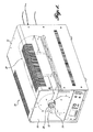
- a representative furnace 10 in accordance with the present invention can have a thin-walled housing including a vented top and side closure member 12, front panel 14, and rear panel 16. These parts connect to and are supported on a base 18.
- the base has a mounting and support structure for the internal core 20 of the furnace.
- the core is cylindrical and, in the illustrated representative embodiment, oriented horizontally.
- the mounting structure can include a concave cradle 22 and an upper mounting clamp or saddle 24. The cradle and saddle hold the heater 26, which can be formed in upper and lower halves.
- the heater has internal heating elements, including separate elements at each end portion and at the central portion.
- the elements heat an internal test zone or cavity.
- the test cavity is the central portion of the internal bore of a longitudinally extending tube 28.
- Power to the heating elements is managed by a controller 30 which can be mounted in the housing base 18. As described in detail below, the controller operates the separate heating elements to maintain an even temperature along at least a major portion of the test cavity.
- heat sensitive elements to be tested or calibrated such as the probes of thermocouples, can be positioned in the test zone (tube bore), such as by insertion through one or more apertures 32 of a front end plug 34.
- the furnace is designed for operation at very high temperatures, such as in the range of 300 C to 1200 C.
- Heat can be dissipated from the housing by one or more fans drawing cooling air through the vents of the housing and exhausting the air through openings in the rear panel 16.
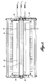
- FIGURE 3 In the plan view of FIGURE 3 (horizontal axial section), it can be seen that the interior of the tube 28 is open and unobstructed.
- the opposite ends of the tube are supported in end plates 40 of the heater component 26, but an annular space 43 is provided between the outer periphery of the tube 30 and the inner periphery of the cylindrical heater 26 along the length of the test zone.
- Temperature sensors 42, 44, and 46 have probes that extend into the annular space 43 at different longitudinal locations.
- the sensors can be high precision thermocouples having stems for mounting the probes to the housing end plate 16 or other appropriate support structure.
- One probe extends a short distance into the space 43, a second probe extends approximately halfway into the space 43, and a third probe extends much farther into the space 43.
- Tube 30 necessarily is a highly heat conductive, high temperature, structurally stable material, such as a high temperature ceramic or quartz. The temperatures sensed by the probes correspond to the temperature inside the tube, i.e., in the test cavity.
- the heater is formed of a high temperature material insulating material in which electric resistance heating elements are partially embedded.
- the heater can be a molded fibrous ceramic, and the conductors C of the heating elements are mounted in slots that open radially inward toward the test cavity.
- Three separate electric resistance heating elements are provided.
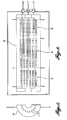
- a first element 50 extends approximately one quarter of the longitudinal length of the heater and encircles a first end portion thereof.
- a second element 52 extends for about one quarter of the length of the heater at the other (second) end thereof.
- the third element 54 extends for about one half the length of the heater in the central portion thereof, in between the end elements 50,52.
- FIGURE 5 the heat producing conductors C of each heating element are closely spaced around the circumference of the heater.
- FIGURES 4 and 5 show the bottom half of the heater, but the top half is the mirror image, and the conductors of each element are connected in series at the top and bottom to form one continuous element that extends 360 degrees around the inner cylindrical space in which the central tube is fitted.
- the average temperature over the region of interest the slope of the temperature profile through the center of the region (i.e., the difference in temperature from one end of the region to the other), and the "curvature" of the temperature profile (variations along the region of interest in the situation where the slope of the temperature profile is not linear). Corrections can be achieved if heat from each of the three heater sections is adjustable relative to the others.
- a controller is provided to manage the amount of power each heater section receives. Time is divided into equal duration control cycles. Within each control cycle, each heater is switched on for a precise amount of time to supply a precise amount of energy. Over many control cycles, the average amount of electric power that the heating elements receive determines the temperature within the furnace. Ideally, each heating element would be controlled independently of the others, in combination with temperature monitoring at a multitude of locations, so that the temperature profile can be fully adjusted and made uniform. In practice, such individual control and complicated monitoring is difficult to achieve and expensive. For example, the furnace with which the present invention is concerned has a power supply of 240 V AC. A 120 V supply would require too much current to produce the necessary amount of power, particularly at higher temperatures. The longer center heating element is rated for 240 V so it can be driven directly from the 240 V mains supply. However, each of the end heating elements is shorter (one-half the length of the center element), with corresponding lower resistance and rated for only 120 V.
- the outer sections To allow the outer sections to operate from 240 V, they have been wired in series with their common current switched by one triac, for example. Another triac controls the power to the center section.
- a problem with this design is that it allows only two independent variables of temperature control.
- the average temperature in the furnace can be adjusted, and typically the curvature of the temperature profile can also be adjusted, but there is no efficient and effective means to adjust the slope of the temperature profile through the center, because the end heating elements always receive the same amount of power.
- one end tends to be colder than the other, which can be due to a variety of factors including differences in performance of the separate heating elements and/or the overall design of the furnace resulting in greater heat loss toward one end than the other.
- the present invention proposes an improved system and circuitry for reconfiguring the connections of the separate heating elements during a control cycle, using the uniform power (preferably 240 V AC), without subjecting the lower rated end heating elements to the full power voltage, but allowing different amounts of power to the respective end elements to achieve a desired temperature profile.
- the uniform power preferably 240 V AC
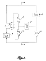
- FIGURE 6 is a simplified block circuit diagram of a representative embodiment.
- the three temperature sensors (thermocouples) 42, 44, 46 each have a dedicated analog-to-digital converter 60, 62, 64, respectively, conveying temperature signals to a processor-controller 66.
- the processor controls a series of solid-state relays 68, 70, 72 that configure the connections of the heating elements 50, 52, 54 to the power supply 74.
- the arrangement of FIGURE 6A is essentially identical, the only difference being that a single analog-to-digital converter 76 is used with a switch 78 for polling the temperature signals from the sensors 42, 44, 46.
- the central processing unit 66 still monitors the temperatures and controls the relays 68, 70, 72 appropriately, adjusting the duty cycle as described in more detail below to achieve the desired uniform temperature profile in the test cavity.
- FIGURE 7 is a diagram of the heating element wiring in a first embodiment of the present invention.
- the system power (preferably 240 V AC) is applied between the top and bottom terminals 80 and 82.
- a branch 84 to the left extends first through one low power rated end heating element 50 and continues to the other of the low power rated end elements 52, then to a first solid state relay 70 (called the "zone” relay) and from there to the other power terminal 82.
- a branch 86 to the right from the top power terminal 80 has a second solid state relay 68 (called the "center” relay) and then extends through the higher power rated center heating element 54 and then to the bottom power terminal 82.
- a third solid state relay (referred to as the "balance" relay) is connected between the first two branches, one end extending from a point between the two end heating elements 50, 52 and a point between the center relay 68 and the center heating element 54.
- heater control can be done in three distinct phases within the control cycle.
- FIGURE 7A during a first phase the center relay 68 is switched on and the balance relay 72 and zone relay 70 are switched off. As indicated by the arrow, current flows only through the center heating element 54.
- the center relay 68 and the balance relay 72 are turned off and the zone relay 70 is turned on. Current flows through first one end heating element 50, then the other 52.
- FIGURE 7C in the third phase within the control cycle, the center relay 68 and the zone relay 70 are turned off, and the balance relay 72 is turned on. Current flows through the first end heating element 50 and through the center heating element 54.
- the above-described scheme allows three dimensions of heater power control, and thus three way adjustment of the temperature profile.
- the total average power all heating elements receive determines the average temperature of the furnace.
- the proportion of time the outer heater sections receive power while the center heater is off determines the amount of curvature there is in the temperature profile.
- the proportion of time only the balance relay is on determines the slope of the temperature profile through the center region.
- the duration of each phase within each control cycle can be adjusted to achieve a uniform temperature profile throughout the center region of the furnace.
- This particular scheme is appropriate when it is known which end of the furnace will tend toward being cooler than the other, such as when the furnace design results in more heat loss at one end, e.g., by greater exposure to the atmosphere or more heat convection at one end.
- the end tending toward a colder temperature can have its heating element configured in a series circuit with the center heating element during the described third phase of the control cycle.
- the controller adjusts the relative durations of the distinct phases of the control cycle based on readings of the temperature sensors.
- the control cycle may be one half second to two seconds long.
- the center heating element it may be necessary for the center heating element to operate for 0.2 seconds, and the end heater elements to operate for approximately the same length of time, but in order to achieve the end-to-end uniform temperature, it may be necessary to operate the balance phase for a period approximately one-half the period of the first and second phases. This can be determined during calibration of the furnace.
- the controller can operate the cycle with the same proportionate time of the three distinct phases, adjusting them to be proportionately longer for a higher desired temperature, and proportionately lower for a lower desired temperature.
- the first and second phases can be performed simultaneously by opening the balance relay while closing both of the center and zone relays, instead of being performed consecutively.
- the duration of the "combined" phase one and two operation can be adjusted accordingly so that the simultaneous supply of power to all three heating elements achieves the same amount of heating as a consectutive operation.
- FIGURE 8 shows a circuit with an additional double pole relay 84 allowing one or the other of the end heaters 50, 52 to be powered concurrently with the center heater 54 in the third phase.
- the control relay 84 shown in the position indicated, and the center and zone relays 68, 70 turned off, and with the balance relay 72 turned on, current will flow through the first end heater 50, the balance relay 72, and the center heater 54.
- the position of the control relay 84 can be switched whereby, again with the center and zone relays 68, 70 open and the balance relay 72 closed, during the third or balance phase of the control cycle, current will flow through both the second end heater element 52 and the center heater element 54.
- operation is the same as for the embodiment described above. More specifically, the center relay 68 can be closed and the balance and zone relays 70, 72 opened such that all current supplied during the first phase passes through the center heating element 54. Similarly, with the balance and center relays 72, 68 open and the zone relay 70 closed, current is passed through both the first and second end heating elements 50, 52 during the second phase.
- the first and second phases can be performed simultaneously by closing both the zone and center relays and opening the balance relay.
- the described invention allows three-way control of the temperature profile. To work well, the duration of each of the phases within each control cycle must be precisely regulated.
- the controller drives the gates or triggers of the relays, switching them on and off at precise times necessary to achieve accurate control of the furnace temperature and temperature profile.
- the controller may, and typically does, use two or more temperature sensors to measure the temperature and the temperature profile, and the controller uses that feedback to make adjustments to the average temperature power and the balance of heater power to correct the temperature and temperature profile. Once the cooler end of the furnace is known, two sensors are effective to achieve adequate feedback, one approximately centered in the test zone (which is centered in the center heating element) and one positioned in the end heating element at the cooler end of the furnace.
- the controller performs all the mathematical calculations necessary to determine how the relays should be switched on and off during each control cycle to achieve stable and uniform temperature control.
- the operating means configures the interconnections of the heating elements so that none of the phases are performed simultaneously. According to another example, none of the phases are performed simultaneously.
Landscapes
- Engineering & Computer Science (AREA)
- Mechanical Engineering (AREA)
- General Engineering & Computer Science (AREA)
- Physics & Mathematics (AREA)
- General Physics & Mathematics (AREA)
- Health & Medical Sciences (AREA)
- Clinical Laboratory Science (AREA)
- Control Of Resistance Heating (AREA)
- Furnace Details (AREA)
- Investigating Or Analyzing Materials Using Thermal Means (AREA)
Applications Claiming Priority (1)
| Application Number | Priority Date | Filing Date | Title |
|---|---|---|---|
| CN201210516574.5A CN103851912B (zh) | 2012-12-05 | 2012-12-05 | 具有可重新配置的加热器电路的高温炉 |
Publications (3)
| Publication Number | Publication Date |
|---|---|
| EP2741040A2 true EP2741040A2 (de) | 2014-06-11 |
| EP2741040A3 EP2741040A3 (de) | 2015-01-14 |
| EP2741040B1 EP2741040B1 (de) | 2016-05-18 |
Family
ID=49911100
Family Applications (1)
| Application Number | Title | Priority Date | Filing Date |
|---|---|---|---|
| EP13195470.3A Active EP2741040B1 (de) | 2012-12-05 | 2013-12-03 | Hochtemperaturofen mit neukonfigurierbaren Heizschaltungen |
Country Status (3)
| Country | Link |
|---|---|
| US (1) | US9681496B2 (de) |
| EP (1) | EP2741040B1 (de) |
| CN (1) | CN103851912B (de) |
Families Citing this family (12)
| Publication number | Priority date | Publication date | Assignee | Title |
|---|---|---|---|---|
| US11513042B2 (en) * | 2015-01-26 | 2022-11-29 | SPEX SamplePrep, LLC | Power-compensated fusion furnace |
| US10240870B2 (en) | 2015-01-26 | 2019-03-26 | Spex Sample Prep, Llc | Method for operating a power-compensated fusion furnace |
| US9851263B2 (en) | 2015-09-29 | 2017-12-26 | Stephen Bugglin | Portable heating chamber system for pyrometric proficiency testing |
| CN105333976A (zh) * | 2015-12-07 | 2016-02-17 | 贵州黎阳航空动力有限公司 | 一种钨钼保护管高温铠装热电偶真空校准装置 |
| CN106017739A (zh) * | 2016-07-28 | 2016-10-12 | 无锡信大气象传感网科技有限公司 | 温度传感器校准装置 |
| CN106248253A (zh) * | 2016-07-28 | 2016-12-21 | 无锡信大气象传感网科技有限公司 | 温度场均匀的温度传感器校准设备 |
| CN106225954A (zh) * | 2016-07-28 | 2016-12-14 | 无锡信大气象传感网科技有限公司 | 具有电磁感应辊加热的温度传感器校准装置 |
| CN106017740A (zh) * | 2016-07-28 | 2016-10-12 | 无锡信大气象传感网科技有限公司 | 便于安装与检修的温度传感器校准设备 |
| CN106017741A (zh) * | 2016-07-28 | 2016-10-12 | 无锡信大气象传感网科技有限公司 | 能密封的气象用光纤传感器温度校准装置 |
| WO2019137343A1 (zh) * | 2018-01-09 | 2019-07-18 | 北京康斯特仪表科技股份有限公司 | 导流散热型干体温度校验仪 |
| US11959814B2 (en) * | 2018-01-09 | 2024-04-16 | Beijing Const Instruments Technology Inc. | High-temperature dry block temperature calibrator |
| CN112146440B (zh) * | 2020-09-29 | 2022-09-27 | 北京康斯特仪表科技股份有限公司 | 可重新配置温区的高温炉及重新配制温区的方法 |
Family Cites Families (16)
| Publication number | Priority date | Publication date | Assignee | Title |
|---|---|---|---|---|
| FI74610B (fi) * | 1986-04-10 | 1987-11-30 | Helo Tehtaat Oy | Elektrisk bastuugn. |
| JP2990030B2 (ja) | 1995-01-09 | 1999-12-13 | 善彦 東 | サウナのヒータ制御装置 |
| US6080971A (en) * | 1997-05-22 | 2000-06-27 | David Seitz | Fluid heater with improved heating elements controller |
| US5900177A (en) | 1997-06-11 | 1999-05-04 | Eaton Corporation | Furnace sidewall temperature control system |
| CN100439897C (zh) * | 2004-12-23 | 2008-12-03 | 中国科学院金属研究所 | 一种热疲劳试验方法 |
| CN1837797A (zh) * | 2006-04-14 | 2006-09-27 | 南京工业大学 | 小冲孔蠕变试验系统 |
| US7607309B2 (en) | 2006-06-14 | 2009-10-27 | Fluke Corporation | Temperature calibration device having reconfigurable heating/cooling modules to provide wide temperature range |
| US7669427B2 (en) | 2006-06-14 | 2010-03-02 | Fluke Corporation | Temperature calibration device driving heating/cooling modules in a manner to allow operation over wide temperature range |
| US8061266B2 (en) * | 2007-03-02 | 2011-11-22 | Track Corp. | Food warming and holding device construction and method |
| JP2008224289A (ja) * | 2007-03-09 | 2008-09-25 | Toppan Printing Co Ltd | 温度サイクル試験装置及び温度サイクル試験方法 |
| CN101183093B (zh) * | 2007-11-08 | 2011-07-27 | 武汉科技大学 | 一种非金属材料高温膨胀力的测定装置及其使用方法 |
| US7909504B2 (en) | 2007-11-14 | 2011-03-22 | Fluke Corporation | Open-loop vertical drywell gradient correction system and method |
| CN101221445A (zh) * | 2007-12-21 | 2008-07-16 | 沈阳重型机械集团有限责任公司 | 数字温度指示调节仪的动态控制功能测试装置 |
| EP2350588B1 (de) | 2008-10-10 | 2014-12-03 | Ametek Denmark A/s | Kalibrationsvorrichtung |
| CN201607292U (zh) * | 2010-02-22 | 2010-10-13 | 西华大学 | 一种温度仪表的自动标定系统 |
| TWI568307B (zh) * | 2011-11-02 | 2017-01-21 | Meng-Hua Yu | Fixed power electric heating device |
-
2012
- 2012-12-05 CN CN201210516574.5A patent/CN103851912B/zh active Active
-
2013
- 2013-02-11 US US13/764,578 patent/US9681496B2/en active Active
- 2013-12-03 EP EP13195470.3A patent/EP2741040B1/de active Active
Non-Patent Citations (1)
| Title |
|---|
| None |
Also Published As
| Publication number | Publication date |
|---|---|
| EP2741040A3 (de) | 2015-01-14 |
| CN103851912B (zh) | 2017-09-08 |
| US9681496B2 (en) | 2017-06-13 |
| US20140153606A1 (en) | 2014-06-05 |
| CN103851912A (zh) | 2014-06-11 |
| EP2741040B1 (de) | 2016-05-18 |
Similar Documents
| Publication | Publication Date | Title |
|---|---|---|
| EP2741040B1 (de) | Hochtemperaturofen mit neukonfigurierbaren Heizschaltungen | |
| JP6616908B2 (ja) | ヒータシステム | |
| JP7379566B2 (ja) | 適応制御用ヒータバンドル及び電流漏れ低減方法 | |
| US11867430B2 (en) | Heater bundle for adaptive control and method of reducing current leakage | |
| US10598646B1 (en) | High dew point humidity sensor | |
| CN109682499A (zh) | 温度计量检定装置用恒温电测装置及恒温控制方法 | |
| US11090211B2 (en) | Heat control device for an incubator for infants, incubator and method for the heat control of an incubator | |
| KR102042753B1 (ko) | 열전 모듈들의 성능을 평가하기 위한 장치 및 시스템 | |
| US20210190379A1 (en) | Heater bundles with local power switching | |
| JPH0612133A (ja) | 恒温庫の温度制御装置 | |
| CN112146440B (zh) | 可重新配置温区的高温炉及重新配制温区的方法 | |
| CA3151372A1 (en) | Heater bundles with local power switching | |
| RU2213960C1 (ru) | Термостат хроматографа | |
| CN106323506B (zh) | 一种测量电阻阻温特性的系统 | |
| KR102883317B1 (ko) | 열구배 보상을 위한 히터 번들 | |
| RU2225993C2 (ru) | Способ регулирования температуры электронагревательных приборов | |
| KR20100006262U (ko) | 자동온도조절 전자레인지 |
Legal Events
| Date | Code | Title | Description |
|---|---|---|---|
| PUAI | Public reference made under article 153(3) epc to a published international application that has entered the european phase |
Free format text: ORIGINAL CODE: 0009012 |
|
| 17P | Request for examination filed |
Effective date: 20131203 |
|
| AK | Designated contracting states |
Kind code of ref document: A2 Designated state(s): AL AT BE BG CH CY CZ DE DK EE ES FI FR GB GR HR HU IE IS IT LI LT LU LV MC MK MT NL NO PL PT RO RS SE SI SK SM TR |
|
| AX | Request for extension of the european patent |
Extension state: BA ME |
|
| PUAL | Search report despatched |
Free format text: ORIGINAL CODE: 0009013 |
|
| AK | Designated contracting states |
Kind code of ref document: A3 Designated state(s): AL AT BE BG CH CY CZ DE DK EE ES FI FR GB GR HR HU IE IS IT LI LT LU LV MC MK MT NL NO PL PT RO RS SE SI SK SM TR |
|
| AX | Request for extension of the european patent |
Extension state: BA ME |
|
| RIC1 | Information provided on ipc code assigned before grant |
Ipc: H05B 1/02 20060101ALI20141208BHEP Ipc: F27B 17/02 20060101AFI20141208BHEP Ipc: F27D 11/00 20060101ALI20141208BHEP Ipc: G01K 15/00 20060101ALI20141208BHEP |
|
| R17P | Request for examination filed (corrected) |
Effective date: 20150609 |
|
| RBV | Designated contracting states (corrected) |
Designated state(s): AL AT BE BG CH CY CZ DE DK EE ES FI FR GB GR HR HU IE IS IT LI LT LU LV MC MK MT NL NO PL PT RO RS SE SI SK SM TR |
|
| RIN1 | Information on inventor provided before grant (corrected) |
Inventor name: YAN, JIA JUN Inventor name: XIA, TIAN Inventor name: WALKER, RICHARD W. |
|
| RIC1 | Information provided on ipc code assigned before grant |
Ipc: F27B 17/02 20060101AFI20151112BHEP Ipc: H05B 1/02 20060101ALI20151112BHEP Ipc: G01K 15/00 20060101ALI20151112BHEP Ipc: F27D 11/00 20060101ALI20151112BHEP |
|
| GRAP | Despatch of communication of intention to grant a patent |
Free format text: ORIGINAL CODE: EPIDOSNIGR1 |
|
| INTG | Intention to grant announced |
Effective date: 20160107 |
|
| GRAS | Grant fee paid |
Free format text: ORIGINAL CODE: EPIDOSNIGR3 |
|
| GRAA | (expected) grant |
Free format text: ORIGINAL CODE: 0009210 |
|
| AK | Designated contracting states |
Kind code of ref document: B1 Designated state(s): AL AT BE BG CH CY CZ DE DK EE ES FI FR GB GR HR HU IE IS IT LI LT LU LV MC MK MT NL NO PL PT RO RS SE SI SK SM TR |
|
| REG | Reference to a national code |
Ref country code: GB Ref legal event code: FG4D |
|
| REG | Reference to a national code |
Ref country code: CH Ref legal event code: EP |
|
| REG | Reference to a national code |
Ref country code: IE Ref legal event code: FG4D Ref country code: AT Ref legal event code: REF Ref document number: 800854 Country of ref document: AT Kind code of ref document: T Effective date: 20160615 |
|
| REG | Reference to a national code |
Ref country code: DE Ref legal event code: R096 Ref document number: 602013007575 Country of ref document: DE |
|
| REG | Reference to a national code |
Ref country code: NL Ref legal event code: MP Effective date: 20160518 |
|
| REG | Reference to a national code |
Ref country code: LT Ref legal event code: MG4D |
|
| PG25 | Lapsed in a contracting state [announced via postgrant information from national office to epo] |
Ref country code: FI Free format text: LAPSE BECAUSE OF FAILURE TO SUBMIT A TRANSLATION OF THE DESCRIPTION OR TO PAY THE FEE WITHIN THE PRESCRIBED TIME-LIMIT Effective date: 20160518 Ref country code: LT Free format text: LAPSE BECAUSE OF FAILURE TO SUBMIT A TRANSLATION OF THE DESCRIPTION OR TO PAY THE FEE WITHIN THE PRESCRIBED TIME-LIMIT Effective date: 20160518 Ref country code: NO Free format text: LAPSE BECAUSE OF FAILURE TO SUBMIT A TRANSLATION OF THE DESCRIPTION OR TO PAY THE FEE WITHIN THE PRESCRIBED TIME-LIMIT Effective date: 20160818 Ref country code: NL Free format text: LAPSE BECAUSE OF FAILURE TO SUBMIT A TRANSLATION OF THE DESCRIPTION OR TO PAY THE FEE WITHIN THE PRESCRIBED TIME-LIMIT Effective date: 20160518 |
|
| REG | Reference to a national code |
Ref country code: AT Ref legal event code: MK05 Ref document number: 800854 Country of ref document: AT Kind code of ref document: T Effective date: 20160518 |
|
| PG25 | Lapsed in a contracting state [announced via postgrant information from national office to epo] |
Ref country code: HR Free format text: LAPSE BECAUSE OF FAILURE TO SUBMIT A TRANSLATION OF THE DESCRIPTION OR TO PAY THE FEE WITHIN THE PRESCRIBED TIME-LIMIT Effective date: 20160518 Ref country code: ES Free format text: LAPSE BECAUSE OF FAILURE TO SUBMIT A TRANSLATION OF THE DESCRIPTION OR TO PAY THE FEE WITHIN THE PRESCRIBED TIME-LIMIT Effective date: 20160518 Ref country code: LV Free format text: LAPSE BECAUSE OF FAILURE TO SUBMIT A TRANSLATION OF THE DESCRIPTION OR TO PAY THE FEE WITHIN THE PRESCRIBED TIME-LIMIT Effective date: 20160518 Ref country code: GR Free format text: LAPSE BECAUSE OF FAILURE TO SUBMIT A TRANSLATION OF THE DESCRIPTION OR TO PAY THE FEE WITHIN THE PRESCRIBED TIME-LIMIT Effective date: 20160819 Ref country code: RS Free format text: LAPSE BECAUSE OF FAILURE TO SUBMIT A TRANSLATION OF THE DESCRIPTION OR TO PAY THE FEE WITHIN THE PRESCRIBED TIME-LIMIT Effective date: 20160518 Ref country code: SE Free format text: LAPSE BECAUSE OF FAILURE TO SUBMIT A TRANSLATION OF THE DESCRIPTION OR TO PAY THE FEE WITHIN THE PRESCRIBED TIME-LIMIT Effective date: 20160518 Ref country code: PT Free format text: LAPSE BECAUSE OF FAILURE TO SUBMIT A TRANSLATION OF THE DESCRIPTION OR TO PAY THE FEE WITHIN THE PRESCRIBED TIME-LIMIT Effective date: 20160919 |
|
| REG | Reference to a national code |
Ref country code: FR Ref legal event code: PLFP Year of fee payment: 4 |
|
| PG25 | Lapsed in a contracting state [announced via postgrant information from national office to epo] |
Ref country code: RO Free format text: LAPSE BECAUSE OF FAILURE TO SUBMIT A TRANSLATION OF THE DESCRIPTION OR TO PAY THE FEE WITHIN THE PRESCRIBED TIME-LIMIT Effective date: 20160518 Ref country code: EE Free format text: LAPSE BECAUSE OF FAILURE TO SUBMIT A TRANSLATION OF THE DESCRIPTION OR TO PAY THE FEE WITHIN THE PRESCRIBED TIME-LIMIT Effective date: 20160518 Ref country code: DK Free format text: LAPSE BECAUSE OF FAILURE TO SUBMIT A TRANSLATION OF THE DESCRIPTION OR TO PAY THE FEE WITHIN THE PRESCRIBED TIME-LIMIT Effective date: 20160518 Ref country code: CZ Free format text: LAPSE BECAUSE OF FAILURE TO SUBMIT A TRANSLATION OF THE DESCRIPTION OR TO PAY THE FEE WITHIN THE PRESCRIBED TIME-LIMIT Effective date: 20160518 Ref country code: SK Free format text: LAPSE BECAUSE OF FAILURE TO SUBMIT A TRANSLATION OF THE DESCRIPTION OR TO PAY THE FEE WITHIN THE PRESCRIBED TIME-LIMIT Effective date: 20160518 |
|
| REG | Reference to a national code |
Ref country code: DE Ref legal event code: R097 Ref document number: 602013007575 Country of ref document: DE |
|
| PG25 | Lapsed in a contracting state [announced via postgrant information from national office to epo] |
Ref country code: AT Free format text: LAPSE BECAUSE OF FAILURE TO SUBMIT A TRANSLATION OF THE DESCRIPTION OR TO PAY THE FEE WITHIN THE PRESCRIBED TIME-LIMIT Effective date: 20160518 Ref country code: SM Free format text: LAPSE BECAUSE OF FAILURE TO SUBMIT A TRANSLATION OF THE DESCRIPTION OR TO PAY THE FEE WITHIN THE PRESCRIBED TIME-LIMIT Effective date: 20160518 Ref country code: PL Free format text: LAPSE BECAUSE OF FAILURE TO SUBMIT A TRANSLATION OF THE DESCRIPTION OR TO PAY THE FEE WITHIN THE PRESCRIBED TIME-LIMIT Effective date: 20160518 Ref country code: BE Free format text: LAPSE BECAUSE OF FAILURE TO SUBMIT A TRANSLATION OF THE DESCRIPTION OR TO PAY THE FEE WITHIN THE PRESCRIBED TIME-LIMIT Effective date: 20160518 |
|
| PLBE | No opposition filed within time limit |
Free format text: ORIGINAL CODE: 0009261 |
|
| STAA | Information on the status of an ep patent application or granted ep patent |
Free format text: STATUS: NO OPPOSITION FILED WITHIN TIME LIMIT |
|
| 26N | No opposition filed |
Effective date: 20170221 |
|
| PG25 | Lapsed in a contracting state [announced via postgrant information from national office to epo] |
Ref country code: SI Free format text: LAPSE BECAUSE OF FAILURE TO SUBMIT A TRANSLATION OF THE DESCRIPTION OR TO PAY THE FEE WITHIN THE PRESCRIBED TIME-LIMIT Effective date: 20160518 |
|
| PG25 | Lapsed in a contracting state [announced via postgrant information from national office to epo] |
Ref country code: MC Free format text: LAPSE BECAUSE OF FAILURE TO SUBMIT A TRANSLATION OF THE DESCRIPTION OR TO PAY THE FEE WITHIN THE PRESCRIBED TIME-LIMIT Effective date: 20160518 |
|
| REG | Reference to a national code |
Ref country code: CH Ref legal event code: PL |
|
| REG | Reference to a national code |
Ref country code: IE Ref legal event code: MM4A |
|
| PG25 | Lapsed in a contracting state [announced via postgrant information from national office to epo] |
Ref country code: LI Free format text: LAPSE BECAUSE OF NON-PAYMENT OF DUE FEES Effective date: 20161231 Ref country code: LU Free format text: LAPSE BECAUSE OF NON-PAYMENT OF DUE FEES Effective date: 20161203 Ref country code: CH Free format text: LAPSE BECAUSE OF NON-PAYMENT OF DUE FEES Effective date: 20161231 |
|
| PG25 | Lapsed in a contracting state [announced via postgrant information from national office to epo] |
Ref country code: IE Free format text: LAPSE BECAUSE OF NON-PAYMENT OF DUE FEES Effective date: 20161203 |
|
| REG | Reference to a national code |
Ref country code: FR Ref legal event code: PLFP Year of fee payment: 5 |
|
| PG25 | Lapsed in a contracting state [announced via postgrant information from national office to epo] |
Ref country code: HU Free format text: LAPSE BECAUSE OF FAILURE TO SUBMIT A TRANSLATION OF THE DESCRIPTION OR TO PAY THE FEE WITHIN THE PRESCRIBED TIME-LIMIT; INVALID AB INITIO Effective date: 20131203 |
|
| PG25 | Lapsed in a contracting state [announced via postgrant information from national office to epo] |
Ref country code: IS Free format text: LAPSE BECAUSE OF FAILURE TO SUBMIT A TRANSLATION OF THE DESCRIPTION OR TO PAY THE FEE WITHIN THE PRESCRIBED TIME-LIMIT Effective date: 20160518 Ref country code: MK Free format text: LAPSE BECAUSE OF FAILURE TO SUBMIT A TRANSLATION OF THE DESCRIPTION OR TO PAY THE FEE WITHIN THE PRESCRIBED TIME-LIMIT Effective date: 20160518 Ref country code: CY Free format text: LAPSE BECAUSE OF FAILURE TO SUBMIT A TRANSLATION OF THE DESCRIPTION OR TO PAY THE FEE WITHIN THE PRESCRIBED TIME-LIMIT Effective date: 20160518 |
|
| PG25 | Lapsed in a contracting state [announced via postgrant information from national office to epo] |
Ref country code: BG Free format text: LAPSE BECAUSE OF FAILURE TO SUBMIT A TRANSLATION OF THE DESCRIPTION OR TO PAY THE FEE WITHIN THE PRESCRIBED TIME-LIMIT Effective date: 20160518 |
|
| PG25 | Lapsed in a contracting state [announced via postgrant information from national office to epo] |
Ref country code: MT Free format text: LAPSE BECAUSE OF NON-PAYMENT OF DUE FEES Effective date: 20161203 |
|
| PG25 | Lapsed in a contracting state [announced via postgrant information from national office to epo] |
Ref country code: TR Free format text: LAPSE BECAUSE OF FAILURE TO SUBMIT A TRANSLATION OF THE DESCRIPTION OR TO PAY THE FEE WITHIN THE PRESCRIBED TIME-LIMIT Effective date: 20160518 Ref country code: AL Free format text: LAPSE BECAUSE OF FAILURE TO SUBMIT A TRANSLATION OF THE DESCRIPTION OR TO PAY THE FEE WITHIN THE PRESCRIBED TIME-LIMIT Effective date: 20160518 |
|
| PGFP | Annual fee paid to national office [announced via postgrant information from national office to epo] |
Ref country code: GB Payment date: 20251229 Year of fee payment: 13 |
|
| PGFP | Annual fee paid to national office [announced via postgrant information from national office to epo] |
Ref country code: IT Payment date: 20251219 Year of fee payment: 13 |
|
| PGFP | Annual fee paid to national office [announced via postgrant information from national office to epo] |
Ref country code: FR Payment date: 20251226 Year of fee payment: 13 |
|
| PGFP | Annual fee paid to national office [announced via postgrant information from national office to epo] |
Ref country code: DE Payment date: 20251229 Year of fee payment: 13 |