EP2740972A2 - Getriebeaggregat für eine landwirtschaftliche Maschine - Google Patents
Getriebeaggregat für eine landwirtschaftliche Maschine Download PDFInfo
- Publication number
- EP2740972A2 EP2740972A2 EP20130184518 EP13184518A EP2740972A2 EP 2740972 A2 EP2740972 A2 EP 2740972A2 EP 20130184518 EP20130184518 EP 20130184518 EP 13184518 A EP13184518 A EP 13184518A EP 2740972 A2 EP2740972 A2 EP 2740972A2
- Authority
- EP
- European Patent Office
- Prior art keywords
- transmission
- partial
- hydrostatic
- unit according
- gear
- Prior art date
- Legal status (The legal status is an assumption and is not a legal conclusion. Google has not performed a legal analysis and makes no representation as to the accuracy of the status listed.)
- Granted
Links
Images

Classifications
-
- B—PERFORMING OPERATIONS; TRANSPORTING
- B60—VEHICLES IN GENERAL
- B60W—CONJOINT CONTROL OF VEHICLE SUB-UNITS OF DIFFERENT TYPE OR DIFFERENT FUNCTION; CONTROL SYSTEMS SPECIALLY ADAPTED FOR HYBRID VEHICLES; ROAD VEHICLE DRIVE CONTROL SYSTEMS FOR PURPOSES NOT RELATED TO THE CONTROL OF A PARTICULAR SUB-UNIT
- B60W10/00—Conjoint control of vehicle sub-units of different type or different function
- B60W10/10—Conjoint control of vehicle sub-units of different type or different function including control of change-speed gearings
- B60W10/101—Infinitely variable gearings
- B60W10/103—Infinitely variable gearings of fluid type
-
- B—PERFORMING OPERATIONS; TRANSPORTING
- B60—VEHICLES IN GENERAL
- B60W—CONJOINT CONTROL OF VEHICLE SUB-UNITS OF DIFFERENT TYPE OR DIFFERENT FUNCTION; CONTROL SYSTEMS SPECIALLY ADAPTED FOR HYBRID VEHICLES; ROAD VEHICLE DRIVE CONTROL SYSTEMS FOR PURPOSES NOT RELATED TO THE CONTROL OF A PARTICULAR SUB-UNIT
- B60W30/00—Purposes of road vehicle drive control systems not related to the control of a particular sub-unit, e.g. of systems using conjoint control of vehicle sub-units
- B60W30/18—Propelling the vehicle
- B60W30/19—Improvement of gear change, e.g. by synchronisation or smoothing gear shift
-
- F—MECHANICAL ENGINEERING; LIGHTING; HEATING; WEAPONS; BLASTING
- F16—ENGINEERING ELEMENTS AND UNITS; GENERAL MEASURES FOR PRODUCING AND MAINTAINING EFFECTIVE FUNCTIONING OF MACHINES OR INSTALLATIONS; THERMAL INSULATION IN GENERAL
- F16H—GEARING
- F16H47/00—Combinations of mechanical gearing with fluid clutches or fluid gearing
- F16H47/02—Combinations of mechanical gearing with fluid clutches or fluid gearing the fluid gearing being of the volumetric type
-
- F—MECHANICAL ENGINEERING; LIGHTING; HEATING; WEAPONS; BLASTING
- F16—ENGINEERING ELEMENTS AND UNITS; GENERAL MEASURES FOR PRODUCING AND MAINTAINING EFFECTIVE FUNCTIONING OF MACHINES OR INSTALLATIONS; THERMAL INSULATION IN GENERAL
- F16H—GEARING
- F16H61/00—Control functions within control units of change-speed- or reversing-gearings for conveying rotary motion ; Control of exclusively fluid gearing, friction gearing, gearings with endless flexible members or other particular types of gearing
- F16H61/38—Control of exclusively fluid gearing
- F16H61/40—Control of exclusively fluid gearing hydrostatic
- F16H61/44—Control of exclusively fluid gearing hydrostatic with more than one pump or motor in operation
- F16H61/448—Control circuits for tandem pumps or motors
-
- B—PERFORMING OPERATIONS; TRANSPORTING
- B60—VEHICLES IN GENERAL
- B60Y—INDEXING SCHEME RELATING TO ASPECTS CROSS-CUTTING VEHICLE TECHNOLOGY
- B60Y2300/00—Purposes or special features of road vehicle drive control systems
- B60Y2300/70—Control of gearings
- B60Y2300/72—Facilitate disengaging of gears, e.g. by inducing a torque reversal
-
- B—PERFORMING OPERATIONS; TRANSPORTING
- B60—VEHICLES IN GENERAL
- B60Y—INDEXING SCHEME RELATING TO ASPECTS CROSS-CUTTING VEHICLE TECHNOLOGY
- B60Y2300/00—Purposes or special features of road vehicle drive control systems
- B60Y2300/70—Control of gearings
- B60Y2300/73—Synchronisation of shaft speeds
-
- F—MECHANICAL ENGINEERING; LIGHTING; HEATING; WEAPONS; BLASTING
- F16—ENGINEERING ELEMENTS AND UNITS; GENERAL MEASURES FOR PRODUCING AND MAINTAINING EFFECTIVE FUNCTIONING OF MACHINES OR INSTALLATIONS; THERMAL INSULATION IN GENERAL
- F16H—GEARING
- F16H47/00—Combinations of mechanical gearing with fluid clutches or fluid gearing
- F16H47/02—Combinations of mechanical gearing with fluid clutches or fluid gearing the fluid gearing being of the volumetric type
- F16H2047/025—Combinations of mechanical gearing with fluid clutches or fluid gearing the fluid gearing being of the volumetric type the fluid gearing comprising a plurality of pumps or motors
Definitions
- the present invention relates to a transmission unit with a mechanical step transmission and a hydrostatic transmission, in particular for use in the travel drive of an agricultural machine.
- a step transmission generally comprises a plurality of sets of gears which mesh with each other at different gear ratios and one of which is coupled to an input shaft and an output shaft of the stepped transmission.
- gear ratio In order to switch the gear ratio of such a gearbox with claw gear via toothed clutches, it is necessary to first relieve the transmission to decouple the currently used gear set can.
- speed ratio of the input and output shafts of the stepped gear In order subsequently to be able to engage another gear set, the speed ratio of the input and output shafts of the stepped gear must be matched to the gear ratio of this gear set.
- the shift begins with the gas take away of the engine, then by disengaging the internal combustion engine is disconnected from the gearbox. Due to the separation from the internal combustion engine and the stepped transmission, only relatively small rotating masses have to be adjusted to the setpoint speed. After the new gear is engaged, the connection between the internal combustion engine and the step transmission can be restored by engaging.
- Out EP 1 100 691 B1 is a hydrostatic transmission with two drivable via a common input shaft pumps and two hydraulic motors known.
- the pumps and hydraulic motors are connected in series with each other via a common loop, so that the two hydraulic motors have equal throughputs of hydraulic fluid.
- unwanted inter-axle slip or axle spin can be avoided.
- the object of the invention is to provide a gear unit with a multi-step transmission and a hydrostatic transmission, in which the hydrostatic transmission allows exact synchronization when switching the stepped transmission.
- the object is achieved by comprising in a gear unit with a mechanical step transmission and a coupled to the stepped transmission hydrostatic transmission, the hydrostatic transmission two parallel to each other with the stepped gear hydrostatic partial transmission and the two partial transmissions are braced against each other when switching the step transmission.
- the tension acts as a load on the other during shifting of one of the partial transmissions, and the variability of its transmission ratio conventionally associated with the no-load state of a hydrostatic transmission is avoided, although the hydrostatic transmission as a whole is not exposed to any external load.
- the partial transmissions should each include a variable displacement pump and an adjustable or constant motor.
- the pumps of both partial transmissions are coupled via a common input shaft or an input-side transmission with a fixed ratio and the hydraulic motors of both partial transmissions via a common output shaft or an output-side transmission with a fixed ratio.
- the two partial transmissions preferably each have their own ring line, which connects the pump and hydraulic motor of the relevant subtransmission and is different from the ring line of the respective other subtransmission.
- the flow-limiting effect of the element is preferably controllable.
- the element by controlling the element so as not to restrict the flow or as little as possible when the hydrostatic transmission drives an external load, efficiency losses due to the different transmission ratios of the two partial transmissions can be avoided without having to match the transmission ratios.
- a flow-limiting element is in particular a pressure relief valve into consideration.
- a pressure limiting valve can be controllable by a limit pressure, at which it opens, is adjustable.
- the transmission ratio should be adjustable independently of the other partial transmission by a control unit on at least one of the partial transmission.
- the transmission ratio of the first partial transmission is set alternately larger and smaller than that of the second partial transmission, differences in the hydrostatic pressure between the two partial transmissions can be kept within predetermined limits.
- pressure sensors are preferably arranged on the ring lines and connected to the control unit.
- a control unit is set up to increase the difference between the transmission ratios of the first and the second partial transmission before switching the stepped transmission.
- the step transmission on the one hand before switching energy efficient preferably with the same setting ratios in the context of adjustment, operated, on the other hand, the required for accurate adjustability of the transmission ratio of the hydrostatic transmission tension is ensured during the shift.
- a control unit of the transmission unit increases the flow-limiting effect of the flux-limiting element before switching the gearbox.
- control unit should expediently also reduce the displacement of the hydraulic motor and the pump of at least one of the partial transmissions.
- Another object of the invention is an agricultural machine with a traction drive, comprising a gear unit as described above.
- FIG. 1 Figure 11 is a block diagram of the powertrain of a mobile agricultural work machine such as a heavy combine harvester.
- a designated 1 diesel engine drives via a common input shaft 2, two pumps P1, P2 of a hydrostatic transmission 3 at the same speed.
- the pump P1 together with a hydraulic motor M1 and a ring line 4, forms a first partial transmission 10 of this hydrostatic transmission 3.
- the ring line 4 has a high-pressure section 6 which extends from an outlet of the pump P1 to an inlet of the hydraulic motor M1, and a low-pressure section 8 which extends from an output of the hydraulic motor M1 to an input of the pump P1.
- the pump P2, the hydraulic motor M2 and a ring line 5 with high and low pressure sections 7, 9 form a second partial transmission 11.
- high pressure section for the line sections 6, 7 and low pressure section for the line sections 8, 9th only as long as the engine 1 drives the movement of the working machine.
- the engine 1 acts as a decelerator, for example when going downhill, higher pressures can occur on the line sections 8, 9 than on the line sections 6, 7.
- the displacement volumes of the pumps P1, P2 and hydraulic motors M1, M2 are controlled by a processor 12, which is connected to a respective pressure sensor 15a, 15b, 15c, 15d at each of the line sections 6, 7, 8, 9.
- the stepped transmission 14 has a direction of rotation sensor 15e for detecting the direction of travel.
- the hydraulic motors M1, M2 are coupled on the output side by driving a step transmission 14 via a common output shaft 13.
- the swirl rates of the two pumps P1, P2 and motors M1, M2 are never exactly identical, so that when they are operated with constant amounts of swirl, the detected by the sensors 15a, 15b pressure difference between the line sections 6, 7 (or even from the pressure difference between the line sections 8, 9 detected by the sensors 15c, 15d increases over time.
- An excessive pressure difference is undesirable because it strains the components of the hydrostatic transmission 3 and restricts the power transferable via the hydrostatic transmission 3: assume, for example, that the sip rates of the pumps and motors are set so that the pressure in the line section 6 becomes higher than in section 7, then the power transmitted by the partial transmission 10 is greater than that transmitted by the partial transmission 11, and it can not both partial transmissions 10, 11 work with their maximum permissible power.
- the motor M1 drives not only the step transmission 14 but also the motor M2 (then operating as a pump), so that part of the power is used for (then operating as a motor)
- Pump P2 flows back and the second partial transmission 11 acts as a load on the first partial transmission 10: the partial transmissions are braced against each other.
- the processor 12 continuously monitors the pressure differences detected by the sensors 15a to 15d and adjusts the amounts of swirls of the pumps and motors as necessary so that a permissible pressure difference between the pipe sections 6 and 7 and between the line sections 8 and 9 is not exceeded.
- the transmission ratio of the first partial transmission 10 is alternately larger and smaller than that of the second partial transmission eleventh
- step transmission 14 In order to change gears in the multi-step transmission 14, it is first necessary to design the current gear and put the stepped gear 14 in a neutral position, in which the output shaft 13 and one of the stepped transmission 14 to a driven axle of the chassis (in a combine generally the front axle) leading output shaft 18 are freely rotatable against each other. The speed ratio of these two shafts 13, 18 must then be adapted to the new gear to be engaged become.
- the step transmission 14 may be provided with conventional lock synchronizers to assist such adjustment, such lock synchronizers are not powerful enough in themselves to compensate for greater rotational speed differences due to the frictional engagement between the shafts 13, 18 made in them.
- the pump of such a hydrostatic transmission works against a load, then its swashplate tends to assume, within that interval, the least possible inclination, corresponding to a minimum displacement, whereas the swashplate of the engine tends to assume the greatest possible inclination within its play .
- the invention makes use of this by preparing the processor 12, the displacement volumes of the pumps P1, P2 and motors M1, M2 adjusted to each other so that they load each other, so that each pump and each engine a sip volume at the edge of by the game assumes given interval.
- the processor 12 increases the displacement of the pump P1 or that of the motor M1 without reducing the same direction on the pump P2 and / or the motor M2, it is achieved that the pressure on the line section 6 increases and decreases to the line section 7. If the pressure on the line section 7 is higher than on the section 9, then the motor M2 is loaded as a pump, ie its volume of swallowing assumes a value at the lower edge of the interval predetermined by the play, while the pump P2 is loaded as a motor, and their swallow volume therefore takes a value at the top of the game interval. In this way, the displacement volumes of all four motors and pumps are precisely defined.
- the transmission ratio of the hydrostatic transmission 3 is exactly controllable, and the rotational speed of the output shaft 13 can be adjusted by adjusting the absorption volumes so precisely to the output shaft 18, that insertion of the new gear without Sperrsynchronisier Anlagenen is possible, or that if the stepped transmission 14th has lock synchronization devices whose overload can be reliably avoided.
- the processor 12 After successful insertion of the new gear, the processor 12 sets again within the setting accuracy equal absorption volumes on both pumps P1, P2 and two hydraulic motors M1, M2. As long as the new gear remains engaged, the processor 12 only makes small corrections to the absorption volumes, if necessary, in order to prevent the pressure differences detected by the sensors 15a and 15b or 15c and 15d from passing a predetermined tolerance interval around 0 leave.
- the processor 12 responds to a gear shift request of a higher-level automatic control unit or the driver of the combine by first calculating the rotational speeds of the shafts 13, 2 which, when the shift request is executed, are calculated from the current driving speed of the combine harvester or the current engine speed Output shaft 18 would result, and checks whether they are within a respective permissible interval. If this is not the case, the switching request must be rejected.
- a subsequent step it is checked whether the pressures on the ring lines 4, 5, in particular in the high-pressure sections 6, 7, are within a permissible interval. Pressures that are above or below this interval may result if the combine harvester e.g. driving up or down an extreme slope.
- the combine harvester e.g. driving up or down an extreme slope.
- the power flow from the diesel engine to the tires is interrupted so that the vehicle could accelerate or decelerate uncontrollably to impermissible speeds during this period. Therefore, in this case, the shift request is ignored or rejected.
- both hydraulic motors M1, M2 are initially adjusted in the direction of small displacement volumes in preparation for switching, wherein at the same time the displacement volumes of the pumps P1, P2 are adjusted to the pressure on the line sections 6, 7 in FIG Course of adjustment to keep substantially constant.
- the drive becomes "softer" in this way as when driving under steady state conditions, ie speed fluctuations of one of the shafts 2, 13 of the hydrostatic transmission are buffered more inside the transmission and not as strong transmitted to the respective other shaft than stationary driving.
- the displacement of the hydraulic motors M1, M2 can not be reduced to zero; the ideal displacement volume for performing the shift operation may vary from one model of one hydrostatic transmission 3 to another and even be different for a given hydrostatic transmission depending on the starting or target gear. Ideal values are to be determined experimentally in a single case.
- the displacement volumes of the pumps P1, P2 are adjusted to lower the hydrostatic pressure on the line sections 6, 7 and thereby relieve the drive train so far that the current gear in the multi-step transmission 14 can be designed.
- the processor 12 switches the step transmission 14 in the neutral position.
- the displacement of one of the two pumps adjusted so that the hydrostatic pressures on the line sections 6, 7 diverging.
- the processor 12 monitors the evolution of the pressures across the sensors 15a-15d.
- the pressure difference between the pipe sections 6, 7 (or 8, 9) exceeds a limit value dependent on the type of pumps P1, P2 and hydraulic motors M1, M2 the pumps P1, P2 and motors M1, M2 are braced against each other so that their swallowing amounts are fixed without play, and the speed of the output shaft 13 can be precisely controlled, either by influencing the speed of the diesel engine 1 or by simultaneously changing the absorption volumes of both pumps P1 , P2 or both motors M1, M2.
- Fig. 1 illustrated embodiment of the invention is in the input shaft 2 and the output shaft 13 each between the two pumps P1, P2 and the two motors M1, M2, a clutch 20 and 21, for example, a dog clutch or a multi-plate clutch provided.
- a clutch 20 and 21 for example, a dog clutch or a multi-plate clutch provided.
- the two pumps P1, P2 may be coupled to one another and to the diesel engine 1 instead of through the common input shaft 2 via a common input-side transmission.
- a common input-side transmission may be necessary if, for reasons of space, not both pumps fit on a common input shaft;
- the gearbox can drive both pumps at the same speed.
- a transmission that drives both pumps with different, but mutually proportional speeds can be useful if the pumps and / or hydraulic motors are not identical, especially if, as described above, one of the partial transmission is not constantly used.
- an output-side transmission the two hydraulic motors M1. M2 with each other and with the step transmission 14 connect.
- the high-pressure sections 6, 7 or the low-pressure sections 8, 9 of the two ring lines 4, 5 are connected to one another by compensating lines 16, 17, each having two antiparallel pressure relief valves 22, 23 have.
- each one of the pressure relief valves 22, 23 opens at each equalization line 16, 17, when a predetermined pressure difference between the line sections 6, 7 or between the line sections 8, 9 is exceeded, a divergence of the pressure difference can be excluded even in a malfunction of the processor 12 ,
- the pressure differential at which the relief valves 22, 23 open is significantly greater than that maintained by the processor 12 in steady-state operation by varying sip rates; in particular, it should be large enough to bring about the tension required between the pumps P1, P2 and motors M1, M2 for precise controllability of the gear ratios of both partial transmissions 10, 11.
- a further modification provides that the pressure difference at which the overpressure valves 22, 23 open can be switched between a value sufficient to produce the tension and a significantly lower value, preferably zero.
- the processor sets the high value only for preparation and during a shift, otherwise, in stationary driving, the relief valves 16, 17 are open.
- no pressure difference between the ring lines 4, 5 form when the ratio of the swallowing quantities of pump and motor in the partial transmissions 10, 11 is different, and the above-described continuous monitoring of the pressure difference and correction of the swallowing quantities, if the pressure difference leaves the tolerance interval, can be omitted.
- Fig. 3 Yet another development of the invention is in Fig. 3 shown.
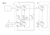
- the hydrostatic transmission 3 and the stepped transmission 14 connected downstream thereof are the same as with reference to FIG Fig. 1 or 2 and will not be explained again. They drive a first axis of an agricultural machine, in the case of a combine, typically the front axle.
- Another hydrostatic transmission 24 with a pump P3 and a hydraulic motor M3 is connected in parallel with the hydrostatic transmission 3 to the diesel engine 1 in order to drive a second axle, in the case of the combine harvester the steerable rear axle.
- the pump P3 of the hydrostatic transmission 24 is here connected to the input shaft 2 of the pumps P1, P2 directly or via a transmission and is selectively disconnectable by a clutch 25 from the diesel engine 1 and the hydrostatic transmission 3.
- the rear axle is not connected here via its own stepped transmission analogous to the stepped transmission 14 with the hydrostatic transmission 24, but only by a further clutch 27 and a simple transmission 26 with unchangeable transmission ratio.
- a further clutch 27 In the closed state of the clutches 25, 27 front and rear axles of the combine harvester are driven.
- the gear ratio of the transmission 26 is adapted to the lowest gear of the stepped gear 14 so that when the lowest gear engaged in the stepped gear 26 and the clutches 25, 27 are closed, wheels on the front and rear axles are driven at the same peripheral speed. This reflects the fact that a four-wheel drive of the combine is generally needed only when driving in the lowest gear;
- the clutches 25, 27 should be opened at the same time in order to prevent lossy running of the hydrostatic transmission 24 in this case.
- the clutch 25 can also be omitted here, if instead of opening the clutch 25, the displacement of the pump P3 is set to zero.
Landscapes
- Engineering & Computer Science (AREA)
- Mechanical Engineering (AREA)
- General Engineering & Computer Science (AREA)
- Transportation (AREA)
- Chemical & Material Sciences (AREA)
- Combustion & Propulsion (AREA)
- Automation & Control Theory (AREA)
- Control Of Fluid Gearings (AREA)
- Control Of Transmission Device (AREA)
- Motor Power Transmission Devices (AREA)
Abstract
Description
- Die vorliegende Erfindung betrifft ein Getriebeaggregat mit einem mechanischen Stufengetriebe und einem hydrostatischen Getriebe, insbesondere zur Verwendung im Fahrantrieb einer landwirtschaftlichen Maschine.
- Ein Stufengetriebe umfasst im Allgemeinen mehrere Sätze von Zahnrädern, die mit unterschiedlichen Übersetzungsverhältnissen miteinander kämmen und von denen jeweils einer an eine Eingangswelle und eine Ausgangswelle des Stufengetriebes koppelbar ist. Um das Übersetzungsverhältnis eines solchen Stufengetriebes mit Klauenschaltung über Zahnkupplungen umzuschalten, ist es notwendig, das Getriebe zunächst zu entlasten, um den gegenwärtig genutzten Zahnradsatz auskoppeln zu können. Damit anschließend ein anderer Zahnradsatz eingekoppelt werden kann, muss das Drehzahlverhältnis von Eingangs- und Ausgangswelle des Stufengetriebes mit dem Übersetzungsverhältnis dieses Zahnradsatzes in Übereinstimmung gebracht werden. Bei Straßenfahrzeugen mit Verbrennungsmotor und rein mechanischem Antriebsstrang beginnt das Schalten mit dem Gaswegnehmen des Verbrennungsmotors, dann wird durch Auskuppeln der Verbrennungsmotor vom Getriebe getrennt. Durch die Trennung vom Verbrennungsmotor und Stufengetriebe müssen nur relativ kleine Drehmassen auf die Solldrehzahl angeglichen werden. Nachdem der neue Gang geschaltet ist, kann durch Einkuppeln die Verbindung zwischen Verbrennungsmotor und Stufengetriebe wieder hergestellt werden.
- Zur Drehzahlangleichung werden Sperrsynchronisiereinrichtungen eingesetzt, die zunächst nur einen Reibkontakt zwischen einem Rad des Radsatzes und einer Welle des Getriebes herstellen und das Zustandekommen einer formschlüssigen Verbindung zwischen Rad und Welle erst freigeben, wenn der Reibkontakt zu einer genauen Angleichung der Drehzahlen von Rad und Welle geführt hat.
- Aus
EP 1 020 314 A2 ist ein Antriebsstrang für ein Fahrzeug bekannt, bei dem ein Verbrennungsmotor ein Stufengetriebe über ein hydrostatisches Getriebe antreibt. Die erforderliche Drehzahlanpassung beim Schalten des Stufengetriebes soll hier durch eine geeignete Steuerung des Übersetzungsverhältnisses des hydrostatischen Getriebes erreicht werden. - In der Praxis zeigt sich jedoch, dass es sehr schwierig ist, das Übersetzungsverhältnis eines hydrostatischen Getriebes im lastfreien Zustand mit der für ein problemloses Schalten des Stufengetriebes erforderlichen Genauigkeit zu steuern. Fehler bei der Drehzahlanpassung können dazu führen, dass der Schaltvorgang misslingt und das Stufengetriebe in Neutralstellung bleibt, oder dass das Einlegen des Gangs zwar gelingt, dabei aber, da die Geschwindigkeit des hydrostatischen Getriebes und des Verbrennungsmotors ruckartig an die Fahrgeschwindigkeit des Fahrzeugs angepasst werden muss, Belastungsspitzen auftreten, die zu hohem Verschleiß und im Laufe der Zeit zu Getriebeschäden führen.
- Es wäre zwar grundsätzlich denkbar, auch in dem Antriebsstrang gemäß
EP 1 020 314 A2 das Stufengetriebe mit herkömmlichen Sperrsynchronisiereinrichtungen auszustatten, doch ist deren Reibverschleiß hier ungleich höher als bei einem rein mechanischen Antriebsstrang, da die Sperrsynchronisiereinrichtung über den Reibkontakt nicht nur die Drehzahl der nicht synchron drehenden Getriebeelemente anpassen muss, sondern zusätzlich auch die des hydrostatischen Getriebes. - Aus
EP 1 100 691 B1 ist ein hydrostatisches Getriebe mit zwei über eine gemeinsame Eingangswelle antreibbaren Pumpen und zwei Hydromotoren bekannt. Die Pumpen und Hydromotoren sind miteinander über eine gemeinsame Ringleitung in Reihe verbunden, so dass die beiden Hydromotoren gleiche Durchsätze an Hydraulikfluid haben. So kann, wenn die zwei Hydromotoren verschiedene Achsen eines Fahrzeugs antreiben, ein unerwünschter Schlupf zwischen den Achsen bzw. ein Durchdrehen einer Achse vermieden werden. - Aufgabe der Erfindung ist, ein Getriebeaggregat mit einem Stufengetriebe und einem hydrostatischen Getriebe zu schaffen, bei dem das hydrostatische Getriebe eine exakte Synchronisierung bei einem Schalten des Stufengetriebes ermöglicht.
- Die Aufgabe wird gelöst, indem bei einem Getriebeaggregat mit einem mechanischen Stufengetriebe und einem an das Stufengetriebe gekoppelten hydrostatischen Getriebe das hydrostatische Getriebe zwei parallel zueinander mit dem Stufengetriebe verbundene hydrostatische Teilgetriebe umfasst und die beiden Teilgetriebe bei einem Schalten des Stufengetriebes gegeneinander verspannt sind. Durch die Verspannung wirkt während des Schaltens eines der Teilgetriebe als Last auf das andere, und die herkömmlicherweise mit dem lastfreien Zustand eines hydrostatischen Getriebes verbundene Variabilität seines Übersetzungsverhältnisses wird vermieden, obwohl das hydrostatische Getriebe als Ganzes keiner äußeren Last ausgesetzt ist.
- Die Teilgetriebe sollten jeweils eine Verstellpumpe und einen Verstell- oder Konstant- Motor umfassen.
- Um die Verspannung aufbauen und halten zu können, sind vorzugsweise die Pumpen beider Teilgetriebe über eine gemeinsame Eingangswelle oder ein eingangsseitiges Getriebe mit fester Übersetzung und die Hydromotoren beider Teilgetriebe über eine gemeinsame Ausgangswelle oder ein ausgangsseitiges Getriebe mit fester Übersetzung gekoppelt.
- Die beiden Teilgetriebe verfügen vorzugsweise jeweils über eine eigene Ringleitung, die Pumpe und Hydromotor des betreffenden Teilgetriebes verbindet und von der Ringleitung des jeweils anderen Teilgetriebes verschieden ist.
- Wenn das hydrostatische Getriebe über längere Zeit betrieben wird und dabei z.B. das Übersetzungsverhältnis des ersten Teilgetriebes höher ist als das des zweiten Teilgetriebes, können sich hohe Druckdifferenzen zwischen den zwei Ringleitungen aufbauen, die, wenn keine Möglichkeit zum Druckausgleich besteht, das hydrostatische Getriebe letztlich zum Blockieren bringen würden. Eine solche Ausgleichsmöglichkeit könnte im einfachsten Fall sich aus Lecks der Pumpen bzw. Hydromotoren ergeben, über die jeweils Druckfluid vom Hochdruckabschnitt in den Niederdruckabschnitt derselben Kreisleitung entweichen kann. Eine bessere Alternative ist, eine Ausgleichsleitung vorzusehen, die die erste und zweite Ringleitung verbindet und ein flussbegrenzendes Element enthält.
- Die flussbegrenzende Wirkung des Elements ist vorzugsweise steuerbar. Indem insbesondere das Element gesteuert wird, um den Fluss nicht oder möglichst wenig zu begrenzen, wenn das hydrostatische Getriebe eine äußere Last antreibt, können Effizienzverluste aufgrund der unterschiedlichen Übersetzungsverhältnisse der zwei Teilgetriebe vermieden werden, ohne dass dafür die Übersetzungsverhältnisse aneinander angeglichen werden müssen.
- Als flussbegrenzendes Element kommt insbesondere ein Druckbegrenzungsventil in Betracht. Ein solches Druckbegrenzungsventil kann steuerbar sein, indem ein Grenzdruck, bei dessen Überschreitung es öffnet, einstellbar ist.
- Das Übersetzungsverhältnis sollte an wenigstens einem der Teilgetriebe unabhängig vom anderen Teilgetriebe durch eine Steuereinheit einstellbar sein.
- Indem insbesondere das Übersetzungsverhältnis des ersten Teilgetriebes abwechselnd größer und kleiner als das des zweiten Teilgetriebes eingestellt wird, können Unterschiede des hydrostatischen Drucks zwischen den beiden Teilgetrieben in vorgegebenen Grenzen gehalten werden.
- Um eine bedarfsgerechte Regelung des Übersetzungsverhältnisses zu ermöglichen, sind vorzugsweise Drucksensoren an den Ringleitungen angeordnet und mit der Steuereinheit verbunden.
- Vorzugweise ist eine Steuereinheit eingerichtet, vor einem Schalten des Stufengetriebes den Unterschied zwischen den Übersetzungsverhältnissen des ersten und des zweiten Teilgetriebes zu erhöhen. So kann das Stufengetriebe einerseits vor dem Schalten energieeffizient, vorzugsweise mit im Rahmen der Einstellgenauigkeit gleichen Übersetzungsverhältnissen, betrieben werden, andererseits ist während des Schaltens die für eine genaue Einstellbarkeit des Übersetzungsverhältnisses des hydrostatischen Getriebes erforderliche Verspannung gewährleistet.
- Die Erhöhung des Unterschiedes des Übersetzungsverhältnisses sollte nach Abschluss des Schaltens natürlich zweckmäßigerweise wieder zurückgenommen werden.
- In analoger Weise kann vorgesehen sein, dass eine Steuereinheit des Getriebeaggregats vor dem Schalten des Schaltgetriebes die flussbegrenzende Wirkung des flussbegrenzenden Elements heraufsetzt.
- Auch diese Wirkung sollte zweckmäßigerweise nach dem Schalten wieder herabgesetzt werden.
- Vor dem Schalten sollte die Steuereinheit zweckmäßigerweise auch das Schluckvolumen von Hydromotor und Pumpe wenigstens eines der Teilgetriebe reduzieren. Je geringer das Schluckvolumen ist, umso geringer ist ein Druckstoß, der beim Einlegen eines neuen Gangs im Stufengetriebe aus einer nicht perfekten Drehzahlanpassung resultiert. Je geringer der Druckstoß ist, umso geringer ist die Belastung des Getriebeaggregats und umso weniger störend spürbar ist das Einlegen des Gangs für den Fahrer eines Fahrzeugs, in dem das Getriebeaggregat verbaut ist.
- Ein weiterer Gegenstand der Erfindung ist eine landwirtschaftliche Arbeitsmaschine mit einem Fahrantrieb, der ein Getriebeaggregat wie oben beschrieben umfasst.
- Weitere Merkmale und Vorteile der Erfindung ergeben sich aus der nachfolgenden Beschreibung von Ausführungsbeispielen unter Bezugnahme auf die beigefügten Figuren. Es zeigen:
- Fig. 1
- eine schematische Darstellung des Antriebsstrangs einer landwirtschaftlichen Arbeitsmaschine gemäß einer ersten Ausgestaltung der Erfindung;
- Fig. 2
- eine schematische Darstellung eines Antriebsstrangs gemäß einer zweiten Ausgestaltung; und
- Fig. 3
- eine schematische Darstellung eines Antriebsstrangs gemäß einer dritten Ausgestaltung der Erfindung.
-
Fig. 1 ist ein Blockdiagramm des Antriebsstrangs einer fahrbaren landwirtschaftlichen Arbeitsmaschine wie etwa eines schweren Mähdreschers. Ein mit 1 bezeichneter Dieselmotor treibt über eine gemeinsame Eingangswelle 2 zwei Pumpen P1, P2 eines hydrostatischen Getriebes 3 mit gleicher Drehzahl an. - Die Pumpe P1 bildet zusammen mit einem Hydromotor M1 und einer Ringleitung 4 ein erstes Teilgetriebe 10 dieses hydrostatischen Getriebes 3. Die Ringleitung 4 hat einen Hochdruckabschnitt 6, der sich von einem Ausgang der Pumpe P1 zu einem Eingang des Hydromotor M1 erstreckt, und einen Niederdruckabschnitt 8, der sich von einem Ausgang des Hydromotors M1 zu einem Eingang der Pumpe P1 erstreckt.
- In analoger Weise bilden die Pumpe P2, der Hydromotor M2 und eine Ringleitung 5 mit Hoch- und Niederdruckabschnitten 7, 9 ein zweites Teilgetriebe 11.
- Streng genommen ist die Bezeichnung Hochdruckabschnitt für die Leitungsabschnitte 6, 7 bzw. Niederdruckabschnitt für die Leitungsabschnitte 8, 9 nur solange richtig, wie der Motor 1 die Bewegung der Arbeitsmaschine antreibt. Wenn der Motor 1, etwa bei Bergabfahrt, verzögernd wirkt, können auf den Leitungsabschnitten 8, 9 höhere Drücke auftreten als auf den Leitungsabschnitten 6,7.
- Die Schluckvolumina der Pumpen P1, P2 und Hydromotoren M1, M2 sind gesteuert durch einen Prozessor 12, der mit je einem Drucksensor 15a, 15b, 15c, 15d an jedem der Leitungsabschnitte 6, 7, 8, 9 verbunden ist. Das Stufengetriebe 14 verfügt zur Erfassung der Fahrtrichtung über einen Drehrichtungssensor 15e.
- Die Hydromotoren M1, M2 sind ausgangsseitig gekoppelt, indem sie über eine gemeinsame Ausgangswelle 13 ein Stufengetriebe 14 antreiben. Die Schluckmengen der zwei Pumpen P1, P2 bzw. Motoren M1, M2 sind niemals exakt identisch, so dass, wenn sie mit gleichbleibenden Schluckmengen betrieben werden, die von den Sensoren 15a, 15b erfasste Druckdifferenz zwischen den Leitungsabschnitten 6, 7 (oder auch die von den Sensoren 15c, 15d erfasste Druckdifferenz zwischen den Leitungsabschnitten 8, 9) im Laufe der Zeit anwächst. Eine übermäßige Druckdifferenz ist unerwünscht, da sie die Komponenten des hydrostatischen Getriebes 3 strapaziert und die über das hydrostatische Getriebe 3 übertragbare Leistung einschränkt: nimmt man z.B. an, dass die Schluckmengen der Pumpen und Motoren so eingestellt sind, dass der Druck im Leitungsabschnitt 6 höher wird als in Abschnitt 7, dann ist die vom Teilgetriebe 10 übertragene Leistung größer als die vom Teilgetriebe 11 übertragene, und es können nicht beide Teilgetriebe 10, 11 mit ihrer maximal zulässigen Leistung arbeiten. Bei ausreichend hoher Druckdifferenz kann es sogar zu einer Umkehr der Leistungsflüsse kommen: der Motor M1 treibt nicht nur das Stufengetriebe 14, sondern auch den (dann als Pumpe arbeitenden) Motor M2 an, so dass ein Teil der Leistung zur (dann als Motor arbeitenden) Pumpe P2 zurückfließt und das zweite Teilgetriebe 11 als Last auf das erste Teilgetriebe 10 wirkt: die Teilgetriebe sind gegeneinander verspannt.
- Um unter stationären Betriebsbedingungen einen solchen Betriebszustand zu vermeiden, überwacht der Prozessor 12 fortlaufend die von den Sensoren 15a bis 15d erfassten Druckdifferenzen und stellt die Schluckmengen der Pumpen und Motoren bei Bedarf nach, so dass eine zulässige Druckdifferenz zwischen den Leitungsabschnitten 6 und 7 bzw. zwischen den Leitungsabschnitten 8 und 9 nicht überschritten wird. Durch dieses Nachstellen wird das Übersetzungsverhältnis des ersten Teilgetriebes 10 abwechselnd größer und kleiner als das des zweiten Teilgetriebes 11.
- Um im Stufengetriebe 14 den Gang zu wechseln, ist es zunächst erforderlich, den aktuellen Gang auszulegen und das Stufengetriebe 14 in eine Neutralstellung zu versetzen, in der die Ausgangswelle 13 und eine vom Stufengetriebe 14 zu einer angetriebenen Achse des Fahrwerks (bei einem Mähdrescher im allgemeinen die Vorderachse) führende Abtriebswelle 18 frei gegeneinander drehbar sind. Das Drehzahlverhältnis dieser beiden Wellen 13, 18 muss anschließend an den neu einzulegenden Gang angepasst werden. Zwar kann das Stufengetriebe 14 zur Unterstützung einer solchen Anpassung mit an sich bekannten Sperrsynchronisiereinrichtungen versehen sein, doch sind solche Sperrsynchronisiereinrichtungen für sich allein nicht leistungsfähig genug, um durch die in ihnen hergestellte reibschlüssige Verbindung zwischen den Wellen 13, 18 größere Drehzahlunterschiede auszugleichen. Bei den meisten derzeit im Handel verfügbaren hydrostatischen Getrieben sind die Schluckvolumina der Pumpen bzw. Motoren nur mit einem gewissen Spiel steuerbar, so dass, wenn das betreffende hydrostatische Getriebe nicht belastet ist, sein Übersetzungsverhältnis innerhalb eines durch dieses Spiel vorgegebene Intervalls beliebige Werte annehmen kann. Wenn hingegen die Pumpe eines solchen hydrostatischen Getriebes gegen eine Last arbeitet, dann neigt ihre Taumelscheibe dazu, innerhalb dieses Intervalls dazu die geringst mögliche Schrägstellung, entsprechend einem minimalen Schluckvolumen, anzunehmen, wohingegen die Taumelscheibe des Motors dazu neigt, innerhalb ihres Spiels die stärkstmögliche Schrägstellung einzunehmen. Die Erfindung macht sich dies zunutze, indem zur Vorbereitung eines Gangwechsels der Prozessor 12 die Schluckvolumina der Pumpen P1, P2 und Motoren M1, M2 so gegeneinander verstellt, dass diese sich gegenseitig belasten, so dass jede Pumpe und jeder Motor ein Schluckvolumen am Rande des durch das Spiel vorgegebenen Intervalls annimmt. Indem der Prozessor 12 im Vergleich zum stationären Betrieb das Schluckvolumen der Pumpe P1 herauf- oder das des Motors M1 herabsetzt, ohne eine gleichsinnige Änderung an der Pumpe P2 und/oder dem Motor M2 vorzunehmen, wird erreicht, dass der Druck auf dem Leitungsabschnitt 6 ansteigt und auf den Leitungsabschnitt 7 abnimmt. Wenn der Druck auf dem Leitungsabschnitt 7 höher ist als auf dem Abschnitt 9, dann ist der Motor M2 als Pumpe belastet, d.h. sein Schluckvolumen nimmt einen Wert am unteren Rand des durch das Spiel vorgegebenen Intervalls an, während die Pumpe P2 als Motor belastet ist, und ihr Schluckvolumen deshalb einen Wert am oberen Rand des Spielintervalls annimmt. Auf diese Weise sind die Schluckvolumina aller vier Motoren und Pumpen genau festgelegt. Dadurch ist das Übersetzungsverhältnis des hydrostatischen Getriebes 3 exakt steuerbar, und die Drehzahl der Ausgangswelle 13 kann durch Einstellen der Schluckvolumina so genau an die der Abtriebswelle 18 angepasst werden, dass ein Einlegen des neuen Gangs ohne Sperrsynchronisiereinrichtungen möglich ist, oder dass, falls das Stufengetriebe 14 über Sperrsynchronisiereinrichtungen verfügt, deren Überlastung zuverlässig vermieden werden kann.
- Nach erfolgreichem Einlegen des neuen Gangs stellt der Prozessor 12 wieder im Rahmen der Einstellgenauigkeit gleiche Schluckvolumina an beiden Pumpen P1, P2 bzw. beiden Hydromotoren M1, M2 ein. Solange der neue Gang eingelegt bleibt, nimmt der Prozessor 12 allenfalls dann noch kleine Korrekturen an den Schluckvolumina vor, wenn dies nötig ist, um zu verhindern, dass die von den Sensoren 15a und 15b bzw. 15c und 15d erfassten Druckdifferenzen ein vorgegebenes Toleranzintervall um 0 verlassen. Einer bevorzugten Ausgestaltung zufolge reagiert der Prozessor 12 auf einen Gangschaltwunsch einer übergeordneten automatischen Steuereinheit oder des Fahrers des Mähdreschers, indem er zunächst die Drehzahlen der Wellen 13, 2 berechnet, die bei Ausführung des Schaltwunsches aus der aktuellen Fahrgeschwindigkeit des Mähdreschers bzw. der aktuellen Drehzahl der Abtriebswelle 18 resultieren würden, und überprüft, ob diese innerhalb eines jeweils zulässigen Intervalls liegen. Ist dies nicht der Fall, muss der Schaltwunsch abgewiesen werden.
- In einem Folgeschritt wird überprüft, ob die Drücke auf den Ringleitungen 4, 5, insbesondere in den Hochdruckabschnitten 6, 7, innerhalb eines zulässigen Intervalls liegen. Drücke, die oberhalb bzw. unterhalb dieses Intervalls liegen, können sich ergeben, wenn der Mähdrescher z.B. einen extremen Hang hinauf- oder hinunterfährt. Während des Gangwechsels ist der Kraftfluss vom Dieselmotor zu den Reifen hin unterbrochen, so dass das Fahrzeug in diesem Zeitraum unkontrolliert auf unzulässige Geschwindigkeiten beschleunigen oder abbremsen könnte. Daher wird auch in diesem Fall der Schaltwunsch ignoriert bzw. abgewiesen.
- Wenn sich jedoch ein Schalten als möglich erweist, dann werden zur Vorbereitung des Schaltens zunächst beide Hydromotoren M1, M2 in Richtung kleiner Schluckvolumina verstellt, wobei gleichzeitig auch die Schluckvolumina der Pumpen P1, P2 angepasst werden, um den Druck auf den Leitungsabschnitten 6, 7 im Laufe der Verstellung im Wesentlichen konstant zu halten. Der Antrieb wird auf diese Weise "weicher" als bei der Fahrt unter stationären Bedingungen, d.h. Drehzahlschwankungen einer der Wellen 2, 13 des hydrostatischen Getriebes werden stärker innerhalb des Getriebes gepuffert und nicht so stark an die jeweils andere Welle übertragen als bei stationärer Fahrt. Natürlich kann das Schluckvolumen der Hydromotoren M1, M2 nicht auf Null reduziert werden; das zum Durchführen des Schaltvorgangs ideale Schluckvolumen kann von einem Modell eines hydrostatischen Getriebes 3 zum anderen variieren und sogar bei einem gegebenen hydrostatischen Getriebe je nach Ausgangs- oder Zielgang unterschiedlich sein. Ideale Werte sind hier im Einzellfall experimentell zu ermitteln.
- Nachdem der zum Schalten ideale Wert des Schluckvolumens an den Hydromotoren M1, M2 erreicht ist, werden anschließend die Schluckvolumina der Pumpen P1, P2 verstellt, um den hydrostatischen Druck auf den Leitungsabschnitten 6, 7 abzusenken und dadurch den Antriebsstrang so weit zu entlasten, dass der aktuelle Gang im Stufengetriebe 14 ausgelegt werden kann. Nun schaltet der Prozessor 12 das Stufengetriebe 14 in die Neutralstellung.
- Als nächstes wird das Schluckvolumen einer der beiden Pumpen, z.B. der Pumpe P2, so verstellt, dass die hydrostatischen Drücke auf den Leitungsabschnitten 6, 7 sich auseinanderentwickeln. Der Prozessor 12 überwacht die Entwicklung der Drücke über die Sensoren 15a-15d. Wenn der Druckunterschied zwischen den Leitungsabschnitten 6, 7 (oder 8, 9) einen von der Bauart der Pumpen P1, P2 und Hydromotoren M1, M2 abhängigen Grenzwert übersteigt, sind die Pumpen P1, P2 und Motoren M1, M2 so gegeneinander verspannt, dass ihre Schluckmengen spielfrei festliegen, und die Drehzahl der Ausgangswelle 13 kann präzise gesteuert werden, sei es durch Beeinflussen der Drehzahl des Dieselmotors 1 oder durch jeweils gleichzeitiges Verändern der Schluckvolumina beider Pumpen P1, P2 oder beider Motoren M1, M2. Wenn auf diese Weise die Drehzahl der Ausgangswelle 13 innerhalb eines vorgegebenen Toleranzbereichs an die Drehzahl der Abtriebswelle 18 und den neu einzulegenden Gang angepasst ist, wird der neue Gang eingelegt. Kleine Anpassungsfehler der Drehzahlen der Wellen 13, 18 führen zwar zu kurzfristigen Drucksprüngen auf den Leitungsabschnitten 6 bis 9, doch aufgrund der vor Beginn des Schaltvorgangs vorgenommenen Reduzierung der Schluckmengen wirken sie sich allenfalls gering auf die Drehzahl des Dieselmotors 1 bzw. die Fahrgeschwindigkeit des Mähdreschers aus.
- Die Schluckvolumina der Pumpen P1, P2 werden nun wieder aneinander angeglichen, so dass die Druckdifferenz zwischen den Leitungen 6, 7 minimiert wird und jeweils wieder beide Pumpen P1, P2 bzw. beide Motoren M1, M2 gleichsinnig belastet sind. Anschließend werden die Schluckvolumina der Pumpen und Motoren auf einen als Funktion von Fahrzeuggeschwindigkeit und Wirkungsgrad vorgegebenen Wert angehoben.
- Einer ebenfalls anhand von
Fig. 1 veranschaulichten Weiterbildung der Erfindung zufolge ist in der Eingangswelle 2 und der Ausgangswelle 13 jeweils zwischen den zwei Pumpen P1, P2 bzw. den zwei Motoren M1, M2 eine Kupplung 20 bzw. 21, z.B. eine Klauenkupplung oder eine Lamellenkupplung, vorgesehen. Indem beide Kupplungen 20, 21 gleichzeitig geöffnet werden, kann das Teilgetriebe 11 aus dem Antriebsstrang ausgekoppelt werden. Wenn der Antriebsstrang gering belastet ist und das Teilgetriebe 10 zur Übertragung der benötigten Antriebsleistung ausreicht, insbesondere bei Straßenfahrt, ermöglicht die Stilllegung des Teilgetriebes 11 eine Reduzierung des Kraftstoffverbrauchs. - Abweichend von der Darstellung der
Fig. 1 können die beiden Pumpen P1, P2 anstatt durch die gemeinsame Eingangswelle 2 auch über ein gemeinsames eingangsseitiges Getriebe aneinander und an den Dieselmotor 1 gekoppelt sein. Ein solches Getriebe kann notwendig sein, wenn aus Platzgründen nicht beide Pumpen an einer gemeinsamen Eingangswelle Platz finden; in diesem Falle kann das Getriebe beide Pumpen mit gleicher Drehzahl antreiben. Ein Getriebe, das beide Pumpen mit unterschiedlichen, aber zueinander proportionalen Drehzahlen antreibt, kann dann zweckmäßig sein, wenn die Pumpen und/oder Hydromotoren nicht baugleich sind, insbesondere wenn, wie oben beschrieben, eines der Teilgetriebe nicht ständig genutzt wird. In analoger Weise kann ein ausgangsseitiges Getriebe die beiden Hydromotoren M1. M2 miteinander und mit dem Stufengetriebe 14 verbinden. - Einer in
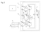
Fig. 2 gezeigten Abwandlung zufolge sind die Hochdruckabschnitte 6, 7 bzw. die Niederdruckabschnitte 8, 9 der zwei Ringleitungen 4, 5 untereinander durch Ausgleichsleitungen 16, 17 verbunden, die jeweils zwei antiparallel angeordnete Überdruckventile 22, 23 aufweisen. Indem jeweils eines der Überdruckventile 22, 23 an jeder Ausgleichsleitung 16, 17 öffnet, wenn eine vorgegebene Druckdifferenz zwischen den Leitungsabschnitten 6, 7 oder zwischen den Leitungsabschnitten 8, 9 überschritten ist, kann ein Divergieren der Druckdifferenz auch bei einer Fehlfunktion des Prozessors 12 ausgeschlossen werden. Die Druckdifferenz, bei der die Überdruckventile 22, 23 öffnen, ist erheblich größer als die vom Prozessor 12 im stationären Betrieb durch variierende Schluckmengen aufrechterhaltene; sie sollte insbesondere groß genug sein, um die für eine genaue Steuerbarkeit der Übersetzungsverhältnisse beider Teilgetriebe 10, 11 erforderliche Verspannung zwischen deren Pumpen P1, P2 und Motoren M1, M2 herbeizuführen. - Eine weitere Abwandlung sieht vor, dass die Druckdifferenz, bei der die Überdruckventile 22, 23 öffnen, zwischen einem zum Herbeiführen der Verspannung ausreichenden Wert und einem deutlich niedrigeren Wert, vorzugsweise Null, umschaltbar ist. Der Prozessor stellt den hohen Wert nur zur Vorbereitung und während eines Schaltvorgangs ein, ansonsten, im stationären Fahrbetrieb, sind die Überdruckventile 16, 17 offen. So kann sich im stationären Betrieb auch dann keine Druckdifferenz zwischen den Ringleitungen 4, 5 ausbilden, wenn das Verhältnis der Schluckmengen von Pumpe und Motor in den Teilgetrieben 10, 11 unterschiedlich ist, und die oben beschriebene fortlaufende Überwachung der Druckdifferenz und Korrektur der Schluckmengen, falls die Druckdifferenz das Toleranzintervall verlässt, kann entfallen.
- Noch eine Weiterentwicklung der Erfindung ist in
Fig. 3 gezeigt. Das hydrostatische Getriebe 3 und das ihm nachgeschaltete Stufengetriebe 14 sind dieselben wie mit Bezug aufFig. 1 oder2 beschrieben und werden nicht erneut erläutert. Sie treiben eine erste Achse einer landwirtschaftlichen Arbeitsmaschine, im Falle eines Mähdreschers typischerweise die Vorderachse, an. Ein weiteres hydrostatisches Getriebe 24 mit einer Pumpe P3 und einem Hydromotor M3 ist parallel zum hydrostatischen Getriebe 3 an den Dieselmotor 1 angeschlossen, um eine zweite Achse, im Falle des Mähdreschers die lenkbare Hinterachse, anzutreiben. Die Pumpe P3 des hydrostatischen Getriebes 24 ist hier mit der Eingangswelle 2 der Pumpen P1, P2 direkt oder über ein Getriebe verbunden und ist durch eine Kupplung 25 selektiv vom Dieselmotor 1 und dem hydrostatischen Getriebe 3 abkuppelbar. Die Hinterachse ist hier jedoch nicht über ein eigenes Stufengetriebe analog dem Stufengetriebe 14 mit dem hydrostatischen Getriebe 24 verbunden, sondern nur durch eine weitere Kupplung 27 und ein einfaches Getriebe 26 mit nicht veränderbarem Übersetzungsverhältnis. Im geschlossenen Zustand der Kupplungen 25, 27 sind Vorderund Hinterachse des Mähdreschers angetrieben. - Das Übersetzungsverhältnis des Getriebes 26 ist an den niedrigsten Gang des Stufengetriebes 14 so angepasst, dass wenn der niedrigste Gang im Stufengetriebe 26 eingelegt und die Kupplungen 25, 27 geschlossen sind, Räder an Vorder- und Hinterachse mit gleicher Umfangsgeschwindigkeit angetrieben sind. Dies spiegelt die Tatsache wider, dass ein Vierradantrieb des Mähdreschers im Allgemeinen nur beim Fahren im niedrigsten Gang benötigt wird; wenn das Stufengetriebe 14 in einen höheren Gang geschaltet wird, sollten gleichzeitig die Kupplungen 25, 27 geöffnet werden, um in diesem Fall ein verlustträchtiges Mitlaufen des hydrostatischen Getriebes 24 zu verhindern. Die Kupplung 25 kann hier auch entfallen, falls anstelle eines Öffnens der Kupplung 25 das Schluckvolumen der Pumpe P3 auf Null gesetzt wird.
- Während eines Umschaltens zwischen dem niedrigsten und einem anderen Gang des Stufengetriebes 14 kann es bei dieser Ausgestaltung zweckmäßig sein, das hydrostatische Getriebe 24 unter Last zu halten. So kann eine vollständige Unterbrechung des Drehmomentflusses zwischen Dieselmotor 1 und den Rädern des Mähdreschers vermieden werden, während das Stufengetriebe 14 in der Neutralstellung ist. Drehzahländerungen aufgrund von Geländeneigung, die bei der Ausgestaltung der
Fig. 1 die Drehzahlanpassung während des Schaltens erschweren, können auf diese Weise vermieden oder zumindest eingeschränkt werden, so dass ein Schalten des Stufengetriebes 14 auch in Fahrsituationen möglich wird, in denen es im Falle der Ausgestaltung derFig. 1 oder2 unterbleiben muss. -
- 1
- Dieselmotor
- 2
- Eingangswelle
- 3
- hydrostatisches Getriebe
- 4
- Ringleitung
- 5
- Ringleitung
- 6
- Hochdruckabschnitt
- 7
- Hochdruckabschnitt
- 8
- Niederdruckabschnitt
- 9
- Niederdruckabschnitt
- 10
- Teilgetriebe
- 11
- Teilgetriebe
- 12
- Prozessor
- 13
- Ausgangswelle
- 14
- Stufengetriebe
- 15
- Sensor
- 16
- Ausgleichsleitung
- 17
- Ausgleichsleitung
- 18
- Abtriebswelle
- 20
- Kupplung
- 21
- Kupplung
- 22
- Überdruckventil
- 23
- Überdruckventil
- 24
- hydrostatisches Getriebe
- 25
- Kupplung
- 26
- Getriebe
- 27
- Kupplung
Claims (13)
- Getriebeaggregat mit einem mechanischen Stufengetriebe (14) und einem an das Stufengetriebe gekoppelten hydrostatischen Getriebe (3), dadurch gekennzeichnet, dass das hydrostatische Getriebe zwei parallel zueinander mit dem Stufengetriebe verbundene hydrostatische Teilgetriebe (10, 11) umfasst und dass die beiden Teilgetriebe (10, 11) bei einem Schalten des Stufengetriebes (14) gegeneinander verspannt sind.
- Getriebeaggregat nach Anspruch 1, dadurch gekennzeichnet, dass Pumpen (P1, P2) beider Teilgetriebe (10, 11) über eine gemeinsame Eingangswelle (2) oder ein eingangsseitiges Getriebe mit fester Übersetzung und Hydromotoren (M1, M2) beider Teilgetriebe (10, 11) über eine gemeinsame Ausgangswelle (13) oder ein ausgangsseitiges Getriebe mit fester Übersetzung miteinander gekoppelt sind.
- Getriebeaggregat nach Anspruch 1 oder 2, dadurch gekennzeichnet, dass die erste Pumpe (P1) und der erste Hydromotor (M1) über eine erste Ringleitung (4) verbunden sind, und dass die zweite Pumpe (P2) und der zweite Hydromotor (M2) über eine von der ersten Ringleitung (4) verschiedene zweite Ringleitung (5) verbunden sind.
- Getriebeaggregat nach Anspruch 3, dadurch gekennzeichnet, dass die erste und die zweite Ringleitung (4, 5) über eine Ausgleichsleitung (16) verbunden sind, die ein flussbegrenzendes Element (22, 23) enthält.
- Getriebeaggregat nach Anspruch 4, dadurch gekennzeichnet, dass die flussbegrenzende Wirkung des Elements (22, 23) steuerbar ist.
- Getriebeaggregat nach Anspruch 4 oder 5, dadurch gekennzeichnet, dass das flussbegrenzende Element ein Druckbegrenzungsventil (22, 23) ist.
- Getriebeaggregat nach einem der vorhergehenden Ansprüche, dadurch gekennzeichnet, dass eine Steuereinheit (12) eingerichtet ist, das Übersetzungsverhältnis des ersten Teilgetriebes (10) unabhängig vom Übersetzungsverhältnis des zweiten Teilgetriebes (11) einzustellen.
- Getriebeaggregat nach Anspruch 7, dadurch gekennzeichnet, dass die Steuereinheit (12) eingerichtet ist, das Übersetzungsverhältnis des ersten Teilgetriebes (10) abwechselnd größer und kleiner als das Übersetzungsverhältnis des zweiten Teilgetriebes (11) einzustellen.
- Getriebeaggregat nach Anspruch 7 oder 8, dadurch gekennzeichnet, dass die Steuereinheit (12) eingerichtet ist, vor einem Schalten des Stufengetriebes (14) den Unterschied zwischen den Übersetzungsverhältnissen des ersten und des zweiten Teilgetriebes (10, 11) zu erhöhen.
- Getriebeaggregat nach einem der Ansprüche 7 bis 9, dadurch gekennzeichnet, dass die Steuereinheit mit an den Ringleitungen (4, 5) angeordneten Drucksensoren (15a-15d) verbunden und eingerichtet ist, das Übersetzungsverhältnis anhand von von den Drucksensoren (15a-15d) gemessenen Drücken zu regeln.
- Getriebeaggregat nach einem der vorhergehenden Ansprüche, dadurch gekennzeichnet, dass eine Steuereinheit (12) eingerichtet ist, vor einem Schalten des Stufengetriebes (14) das Schluckvolumen von Hydromotor (M1, M2) und Pumpe (P1, P2) wenigstens eines der Teilgetriebe (10, 11) zu reduzieren.
- Landwirtschaftliche Arbeitsmaschine, gekennzeichnet durch einen Fahrantrieb, der ein Getriebeaggregat nach einem der vorhergehenden Ansprüche umfasst.
- Landwirtschaftliche Arbeitsmaschine nach Anspruch 12, dadurch gekennzeichnet, dass das hydrostatische Getriebe (3) ein erstes hydrostatisches Getriebe zum Antreiben einer ersten Achse der Maschine ist und ein zweites hydrostatisches Getriebe (24) zum Antreiben einer zweiten Achse der Arbeitsmaschine an eine Eingangswelle (2) des ersten hydrostatischen Getriebes (3) koppelbar ist.
Applications Claiming Priority (1)
| Application Number | Priority Date | Filing Date | Title |
|---|---|---|---|
| DE201210024068 DE102012024068A1 (de) | 2012-12-10 | 2012-12-10 | Getriebeaggregat für eine landwirtschaftliche Maschine |
Publications (3)
| Publication Number | Publication Date |
|---|---|
| EP2740972A2 true EP2740972A2 (de) | 2014-06-11 |
| EP2740972A3 EP2740972A3 (de) | 2015-06-17 |
| EP2740972B1 EP2740972B1 (de) | 2016-11-09 |
Family
ID=49212617
Family Applications (1)
| Application Number | Title | Priority Date | Filing Date |
|---|---|---|---|
| EP13184518.2A Not-in-force EP2740972B1 (de) | 2012-12-10 | 2013-09-16 | Getriebeaggregat für eine landwirtschaftliche Maschine |
Country Status (2)
| Country | Link |
|---|---|
| EP (1) | EP2740972B1 (de) |
| DE (1) | DE102012024068A1 (de) |
Cited By (1)
| Publication number | Priority date | Publication date | Assignee | Title |
|---|---|---|---|---|
| WO2016006454A1 (ja) * | 2014-07-11 | 2016-01-14 | Kyb株式会社 | 液圧駆動システム |
Families Citing this family (2)
| Publication number | Priority date | Publication date | Assignee | Title |
|---|---|---|---|---|
| EP3009716A1 (de) | 2014-10-16 | 2016-04-20 | Dana Italia S.p.A. | Zweimotorige Antriebseinheit und Verfahren zur kraftbetriebenen Kopplung einer ersten zweimotorigen Antriebseinheit mit einer Antriebswelle |
| DE102017216621A1 (de) | 2017-09-20 | 2019-03-21 | Continental Automotive Gmbh | Rotor für einen Turbolader |
Citations (2)
| Publication number | Priority date | Publication date | Assignee | Title |
|---|---|---|---|---|
| EP1020314A2 (de) | 1999-01-15 | 2000-07-19 | Sauer-Sundstrand Gmbh | Antriebsstrang für ein Fahrzeug und Verfahren zum Steuern eines Antriebsstranges |
| EP1100691B1 (de) | 1998-07-28 | 2002-08-28 | Brueninghaus Hydromatik Gmbh | Hydrostatischer fahrantrieb mit differentialsperre |
Family Cites Families (4)
| Publication number | Priority date | Publication date | Assignee | Title |
|---|---|---|---|---|
| US3166952A (en) * | 1961-10-19 | 1965-01-26 | Richard E Lang | Drive systems |
| JPS5656472U (de) * | 1979-10-09 | 1981-05-16 | ||
| DE4223846C2 (de) * | 1992-07-20 | 1996-03-28 | Hydromatik Gmbh | Getriebeeinheit zur Anordnung zwischen einem Antriebsmotor und einem Verbraucher |
| US8306707B2 (en) * | 2007-11-08 | 2012-11-06 | Parker-Hannifin Corporation | Transmission shifting with speed dither and torque dither |
-
2012
- 2012-12-10 DE DE201210024068 patent/DE102012024068A1/de not_active Withdrawn
-
2013
- 2013-09-16 EP EP13184518.2A patent/EP2740972B1/de not_active Not-in-force
Patent Citations (2)
| Publication number | Priority date | Publication date | Assignee | Title |
|---|---|---|---|---|
| EP1100691B1 (de) | 1998-07-28 | 2002-08-28 | Brueninghaus Hydromatik Gmbh | Hydrostatischer fahrantrieb mit differentialsperre |
| EP1020314A2 (de) | 1999-01-15 | 2000-07-19 | Sauer-Sundstrand Gmbh | Antriebsstrang für ein Fahrzeug und Verfahren zum Steuern eines Antriebsstranges |
Cited By (1)
| Publication number | Priority date | Publication date | Assignee | Title |
|---|---|---|---|---|
| WO2016006454A1 (ja) * | 2014-07-11 | 2016-01-14 | Kyb株式会社 | 液圧駆動システム |
Also Published As
| Publication number | Publication date |
|---|---|
| EP2740972B1 (de) | 2016-11-09 |
| EP2740972A3 (de) | 2015-06-17 |
| DE102012024068A1 (de) | 2014-06-12 |
Similar Documents
| Publication | Publication Date | Title |
|---|---|---|
| EP1150040B1 (de) | Hydraulische Schaltung für ein automatisiertes Doppelkupplungsgetriebe für Kraftfahrzeuge | |
| DE102004043017B4 (de) | Steuerungssystem eines hydromechanischen Getriebes | |
| DE3207938C2 (de) | Unter Last schaltbare mechanische Getriebeanordnung | |
| EP3043089A1 (de) | Hydraulikmittelaufbereitung einer getriebehydraulik und verfahren zum betrieb der getriebehydraulik | |
| DE112012006767T5 (de) | Fahrzeuggetriebesteuerung | |
| WO2005019676A1 (de) | Verfahren zur steuerung eines doppelkupplungsgetriebes | |
| DE102004053533A1 (de) | Fahrzeugsteuerungssystem | |
| EP2461073B1 (de) | Hydromechanisches Getriebe | |
| EP2740972B1 (de) | Getriebeaggregat für eine landwirtschaftliche Maschine | |
| DE10133358B4 (de) | Hydrostatischer Antrieb und Verfahren zum Wechseln von Gängen eines einem hydrostatischen Getriebe nachgeschalteten Schaltgetriebes | |
| DE102009053031A1 (de) | Hydrostatisches Getriebe | |
| EP1357309A2 (de) | Verfahren zur Steuerung eines Anfahrvorgangs mit einem Doppelkupplungsgetriebe | |
| DE102011100799B4 (de) | Doppelkupplungsgetriebe, Verfahren zum Betreiben | |
| WO2002095268A1 (de) | Getriebesysteme | |
| DE19845604C5 (de) | Stufengetriebe und Verfahren zum Auslegen eines Ganges eines Stufengetriebes | |
| DE102010001696A1 (de) | Verfahren zum Einstellen einer fahrerwunschabhängigen Soll-Drehzahl | |
| WO2009021584A1 (de) | Schaltgetriebe | |
| WO2005008103A1 (de) | Verfahren zum schalten eines doppelkupplungsgetriebes eines kraftfahrzeuges | |
| DE931268C (de) | Vorrichtung zum selbsttaetigen hydraulischen Schalten von Wechselgetrieben, insbesondere fuer Kraftfahrzeuge | |
| DE102012203582B4 (de) | Verfahren zur Schaltsteuerung eines automatisierten Gruppengetriebes | |
| DE102019218901A1 (de) | Fahrantrieb für ein Fahrzeug mit einem Fahrgetriebe und Steuerarchitektur zum Steuern des Fahrgetriebes | |
| DE102011055174B4 (de) | Verfahren zum Schalten eines zwischen mindestens zwei Übersetzungsstufen schaltbaren Schaltgetriebes eines Fahrantriebs | |
| EP3882487B1 (de) | Verfahren zum schalten eines verbundgetriebes | |
| EP1216369B1 (de) | Notsteuerung für ein kraftfahrzeug | |
| EP0429525B1 (de) | Einrichtung und verfahren zum betrieb einer verstellbaren antriebseinheit |
Legal Events
| Date | Code | Title | Description |
|---|---|---|---|
| PUAI | Public reference made under article 153(3) epc to a published international application that has entered the european phase |
Free format text: ORIGINAL CODE: 0009012 |
|
| 17P | Request for examination filed |
Effective date: 20130916 |
|
| AK | Designated contracting states |
Kind code of ref document: A2 Designated state(s): AL AT BE BG CH CY CZ DE DK EE ES FI FR GB GR HR HU IE IS IT LI LT LU LV MC MK MT NL NO PL PT RO RS SE SI SK SM TR |
|
| AX | Request for extension of the european patent |
Extension state: BA ME |
|
| PUAL | Search report despatched |
Free format text: ORIGINAL CODE: 0009013 |
|
| AK | Designated contracting states |
Kind code of ref document: A3 Designated state(s): AL AT BE BG CH CY CZ DE DK EE ES FI FR GB GR HR HU IE IS IT LI LT LU LV MC MK MT NL NO PL PT RO RS SE SI SK SM TR |
|
| AX | Request for extension of the european patent |
Extension state: BA ME |
|
| RIC1 | Information provided on ipc code assigned before grant |
Ipc: F16H 47/02 20060101ALI20150513BHEP Ipc: B60W 10/103 20120101ALI20150513BHEP Ipc: B60W 30/19 20120101ALI20150513BHEP Ipc: F16H 61/448 20100101AFI20150513BHEP |
|
| R17P | Request for examination filed (corrected) |
Effective date: 20151217 |
|
| RBV | Designated contracting states (corrected) |
Designated state(s): AL AT BE BG CH CY CZ DE DK EE ES FI FR GB GR HR HU IE IS IT LI LT LU LV MC MK MT NL NO PL PT RO RS SE SI SK SM TR |
|
| GRAP | Despatch of communication of intention to grant a patent |
Free format text: ORIGINAL CODE: EPIDOSNIGR1 |
|
| INTG | Intention to grant announced |
Effective date: 20160624 |
|
| GRAS | Grant fee paid |
Free format text: ORIGINAL CODE: EPIDOSNIGR3 |
|
| GRAA | (expected) grant |
Free format text: ORIGINAL CODE: 0009210 |
|
| AK | Designated contracting states |
Kind code of ref document: B1 Designated state(s): AL AT BE BG CH CY CZ DE DK EE ES FI FR GB GR HR HU IE IS IT LI LT LU LV MC MK MT NL NO PL PT RO RS SE SI SK SM TR |
|
| REG | Reference to a national code |
Ref country code: GB Ref legal event code: FG4D Free format text: NOT ENGLISH |
|
| REG | Reference to a national code |
Ref country code: AT Ref legal event code: REF Ref document number: 844249 Country of ref document: AT Kind code of ref document: T Effective date: 20161115 Ref country code: CH Ref legal event code: EP |
|
| REG | Reference to a national code |
Ref country code: IE Ref legal event code: FG4D Free format text: LANGUAGE OF EP DOCUMENT: GERMAN |
|
| REG | Reference to a national code |
Ref country code: DE Ref legal event code: R096 Ref document number: 502013005276 Country of ref document: DE |
|
| PG25 | Lapsed in a contracting state [announced via postgrant information from national office to epo] |
Ref country code: LV Free format text: LAPSE BECAUSE OF FAILURE TO SUBMIT A TRANSLATION OF THE DESCRIPTION OR TO PAY THE FEE WITHIN THE PRESCRIBED TIME-LIMIT Effective date: 20161109 |
|
| REG | Reference to a national code |
Ref country code: LT Ref legal event code: MG4D |
|
| REG | Reference to a national code |
Ref country code: NL Ref legal event code: MP Effective date: 20161109 |
|
| PG25 | Lapsed in a contracting state [announced via postgrant information from national office to epo] |
Ref country code: GR Free format text: LAPSE BECAUSE OF FAILURE TO SUBMIT A TRANSLATION OF THE DESCRIPTION OR TO PAY THE FEE WITHIN THE PRESCRIBED TIME-LIMIT Effective date: 20170210 Ref country code: LT Free format text: LAPSE BECAUSE OF FAILURE TO SUBMIT A TRANSLATION OF THE DESCRIPTION OR TO PAY THE FEE WITHIN THE PRESCRIBED TIME-LIMIT Effective date: 20161109 Ref country code: NL Free format text: LAPSE BECAUSE OF FAILURE TO SUBMIT A TRANSLATION OF THE DESCRIPTION OR TO PAY THE FEE WITHIN THE PRESCRIBED TIME-LIMIT Effective date: 20161109 Ref country code: SE Free format text: LAPSE BECAUSE OF FAILURE TO SUBMIT A TRANSLATION OF THE DESCRIPTION OR TO PAY THE FEE WITHIN THE PRESCRIBED TIME-LIMIT Effective date: 20161109 Ref country code: NO Free format text: LAPSE BECAUSE OF FAILURE TO SUBMIT A TRANSLATION OF THE DESCRIPTION OR TO PAY THE FEE WITHIN THE PRESCRIBED TIME-LIMIT Effective date: 20170209 |
|
| PG25 | Lapsed in a contracting state [announced via postgrant information from national office to epo] |
Ref country code: IS Free format text: LAPSE BECAUSE OF FAILURE TO SUBMIT A TRANSLATION OF THE DESCRIPTION OR TO PAY THE FEE WITHIN THE PRESCRIBED TIME-LIMIT Effective date: 20170309 Ref country code: ES Free format text: LAPSE BECAUSE OF FAILURE TO SUBMIT A TRANSLATION OF THE DESCRIPTION OR TO PAY THE FEE WITHIN THE PRESCRIBED TIME-LIMIT Effective date: 20161109 Ref country code: RS Free format text: LAPSE BECAUSE OF FAILURE TO SUBMIT A TRANSLATION OF THE DESCRIPTION OR TO PAY THE FEE WITHIN THE PRESCRIBED TIME-LIMIT Effective date: 20161109 Ref country code: HR Free format text: LAPSE BECAUSE OF FAILURE TO SUBMIT A TRANSLATION OF THE DESCRIPTION OR TO PAY THE FEE WITHIN THE PRESCRIBED TIME-LIMIT Effective date: 20161109 Ref country code: FI Free format text: LAPSE BECAUSE OF FAILURE TO SUBMIT A TRANSLATION OF THE DESCRIPTION OR TO PAY THE FEE WITHIN THE PRESCRIBED TIME-LIMIT Effective date: 20161109 Ref country code: PL Free format text: LAPSE BECAUSE OF FAILURE TO SUBMIT A TRANSLATION OF THE DESCRIPTION OR TO PAY THE FEE WITHIN THE PRESCRIBED TIME-LIMIT Effective date: 20161109 Ref country code: PT Free format text: LAPSE BECAUSE OF FAILURE TO SUBMIT A TRANSLATION OF THE DESCRIPTION OR TO PAY THE FEE WITHIN THE PRESCRIBED TIME-LIMIT Effective date: 20170309 |
|
| PG25 | Lapsed in a contracting state [announced via postgrant information from national office to epo] |
Ref country code: RO Free format text: LAPSE BECAUSE OF FAILURE TO SUBMIT A TRANSLATION OF THE DESCRIPTION OR TO PAY THE FEE WITHIN THE PRESCRIBED TIME-LIMIT Effective date: 20161109 Ref country code: DK Free format text: LAPSE BECAUSE OF FAILURE TO SUBMIT A TRANSLATION OF THE DESCRIPTION OR TO PAY THE FEE WITHIN THE PRESCRIBED TIME-LIMIT Effective date: 20161109 Ref country code: SK Free format text: LAPSE BECAUSE OF FAILURE TO SUBMIT A TRANSLATION OF THE DESCRIPTION OR TO PAY THE FEE WITHIN THE PRESCRIBED TIME-LIMIT Effective date: 20161109 Ref country code: CZ Free format text: LAPSE BECAUSE OF FAILURE TO SUBMIT A TRANSLATION OF THE DESCRIPTION OR TO PAY THE FEE WITHIN THE PRESCRIBED TIME-LIMIT Effective date: 20161109 Ref country code: EE Free format text: LAPSE BECAUSE OF FAILURE TO SUBMIT A TRANSLATION OF THE DESCRIPTION OR TO PAY THE FEE WITHIN THE PRESCRIBED TIME-LIMIT Effective date: 20161109 |
|
| REG | Reference to a national code |
Ref country code: DE Ref legal event code: R097 Ref document number: 502013005276 Country of ref document: DE |
|
| PG25 | Lapsed in a contracting state [announced via postgrant information from national office to epo] |
Ref country code: BG Free format text: LAPSE BECAUSE OF FAILURE TO SUBMIT A TRANSLATION OF THE DESCRIPTION OR TO PAY THE FEE WITHIN THE PRESCRIBED TIME-LIMIT Effective date: 20170209 Ref country code: SM Free format text: LAPSE BECAUSE OF FAILURE TO SUBMIT A TRANSLATION OF THE DESCRIPTION OR TO PAY THE FEE WITHIN THE PRESCRIBED TIME-LIMIT Effective date: 20161109 Ref country code: IT Free format text: LAPSE BECAUSE OF FAILURE TO SUBMIT A TRANSLATION OF THE DESCRIPTION OR TO PAY THE FEE WITHIN THE PRESCRIBED TIME-LIMIT Effective date: 20161109 |
|
| PLBE | No opposition filed within time limit |
Free format text: ORIGINAL CODE: 0009261 |
|
| STAA | Information on the status of an ep patent application or granted ep patent |
Free format text: STATUS: NO OPPOSITION FILED WITHIN TIME LIMIT |
|
| 26N | No opposition filed |
Effective date: 20170810 |
|
| PG25 | Lapsed in a contracting state [announced via postgrant information from national office to epo] |
Ref country code: SI Free format text: LAPSE BECAUSE OF FAILURE TO SUBMIT A TRANSLATION OF THE DESCRIPTION OR TO PAY THE FEE WITHIN THE PRESCRIBED TIME-LIMIT Effective date: 20161109 |
|
| REG | Reference to a national code |
Ref country code: CH Ref legal event code: PL |
|
| GBPC | Gb: european patent ceased through non-payment of renewal fee |
Effective date: 20170916 |
|
| PG25 | Lapsed in a contracting state [announced via postgrant information from national office to epo] |
Ref country code: MC Free format text: LAPSE BECAUSE OF FAILURE TO SUBMIT A TRANSLATION OF THE DESCRIPTION OR TO PAY THE FEE WITHIN THE PRESCRIBED TIME-LIMIT Effective date: 20161109 |
|
| REG | Reference to a national code |
Ref country code: IE Ref legal event code: MM4A |
|
| REG | Reference to a national code |
Ref country code: BE Ref legal event code: MM Effective date: 20170930 |
|
| PG25 | Lapsed in a contracting state [announced via postgrant information from national office to epo] |
Ref country code: LU Free format text: LAPSE BECAUSE OF NON-PAYMENT OF DUE FEES Effective date: 20170916 |
|
| REG | Reference to a national code |
Ref country code: FR Ref legal event code: ST Effective date: 20180531 |
|
| PG25 | Lapsed in a contracting state [announced via postgrant information from national office to epo] |
Ref country code: LI Free format text: LAPSE BECAUSE OF NON-PAYMENT OF DUE FEES Effective date: 20170930 Ref country code: GB Free format text: LAPSE BECAUSE OF NON-PAYMENT OF DUE FEES Effective date: 20170916 Ref country code: CH Free format text: LAPSE BECAUSE OF NON-PAYMENT OF DUE FEES Effective date: 20170930 Ref country code: IE Free format text: LAPSE BECAUSE OF NON-PAYMENT OF DUE FEES Effective date: 20170916 |
|
| PG25 | Lapsed in a contracting state [announced via postgrant information from national office to epo] |
Ref country code: FR Free format text: LAPSE BECAUSE OF NON-PAYMENT OF DUE FEES Effective date: 20171002 Ref country code: BE Free format text: LAPSE BECAUSE OF NON-PAYMENT OF DUE FEES Effective date: 20170930 |
|
| PG25 | Lapsed in a contracting state [announced via postgrant information from national office to epo] |
Ref country code: MT Free format text: LAPSE BECAUSE OF FAILURE TO SUBMIT A TRANSLATION OF THE DESCRIPTION OR TO PAY THE FEE WITHIN THE PRESCRIBED TIME-LIMIT Effective date: 20161109 |
|
| PG25 | Lapsed in a contracting state [announced via postgrant information from national office to epo] |
Ref country code: HU Free format text: LAPSE BECAUSE OF FAILURE TO SUBMIT A TRANSLATION OF THE DESCRIPTION OR TO PAY THE FEE WITHIN THE PRESCRIBED TIME-LIMIT; INVALID AB INITIO Effective date: 20130916 |
|
| PG25 | Lapsed in a contracting state [announced via postgrant information from national office to epo] |
Ref country code: CY Free format text: LAPSE BECAUSE OF NON-PAYMENT OF DUE FEES Effective date: 20161109 |
|
| REG | Reference to a national code |
Ref country code: AT Ref legal event code: MM01 Ref document number: 844249 Country of ref document: AT Kind code of ref document: T Effective date: 20180916 |
|
| PG25 | Lapsed in a contracting state [announced via postgrant information from national office to epo] |
Ref country code: MK Free format text: LAPSE BECAUSE OF FAILURE TO SUBMIT A TRANSLATION OF THE DESCRIPTION OR TO PAY THE FEE WITHIN THE PRESCRIBED TIME-LIMIT Effective date: 20161109 |
|
| PG25 | Lapsed in a contracting state [announced via postgrant information from national office to epo] |
Ref country code: AT Free format text: LAPSE BECAUSE OF NON-PAYMENT OF DUE FEES Effective date: 20180916 |
|
| PG25 | Lapsed in a contracting state [announced via postgrant information from national office to epo] |
Ref country code: TR Free format text: LAPSE BECAUSE OF FAILURE TO SUBMIT A TRANSLATION OF THE DESCRIPTION OR TO PAY THE FEE WITHIN THE PRESCRIBED TIME-LIMIT Effective date: 20161109 |
|
| PG25 | Lapsed in a contracting state [announced via postgrant information from national office to epo] |
Ref country code: AL Free format text: LAPSE BECAUSE OF FAILURE TO SUBMIT A TRANSLATION OF THE DESCRIPTION OR TO PAY THE FEE WITHIN THE PRESCRIBED TIME-LIMIT Effective date: 20161109 |
|
| P01 | Opt-out of the competence of the unified patent court (upc) registered |
Effective date: 20230515 |
|
| PGFP | Annual fee paid to national office [announced via postgrant information from national office to epo] |
Ref country code: DE Payment date: 20230920 Year of fee payment: 11 |
|
| REG | Reference to a national code |
Ref country code: DE Ref legal event code: R119 Ref document number: 502013005276 Country of ref document: DE |
|
| PG25 | Lapsed in a contracting state [announced via postgrant information from national office to epo] |
Ref country code: DE Free format text: LAPSE BECAUSE OF NON-PAYMENT OF DUE FEES Effective date: 20250401 |