EP2740503A1 - Chargeur d'assemblage d'aiguille - Google Patents
Chargeur d'assemblage d'aiguille Download PDFInfo
- Publication number
- EP2740503A1 EP2740503A1 EP12196101.5A EP12196101A EP2740503A1 EP 2740503 A1 EP2740503 A1 EP 2740503A1 EP 12196101 A EP12196101 A EP 12196101A EP 2740503 A1 EP2740503 A1 EP 2740503A1
- Authority
- EP
- European Patent Office
- Prior art keywords
- needle
- needle assembly
- magazine
- guard
- distal
- Prior art date
- Legal status (The legal status is an assumption and is not a legal conclusion. Google has not performed a legal analysis and makes no representation as to the accuracy of the status listed.)
- Ceased
Links
Images


Classifications
-
- A—HUMAN NECESSITIES
- A61—MEDICAL OR VETERINARY SCIENCE; HYGIENE
- A61M—DEVICES FOR INTRODUCING MEDIA INTO, OR ONTO, THE BODY; DEVICES FOR TRANSDUCING BODY MEDIA OR FOR TAKING MEDIA FROM THE BODY; DEVICES FOR PRODUCING OR ENDING SLEEP OR STUPOR
- A61M5/00—Devices for bringing media into the body in a subcutaneous, intra-vascular or intramuscular way; Accessories therefor, e.g. filling or cleaning devices, arm-rests
- A61M5/002—Packages specially adapted therefor, e.g. for syringes or needles, kits for diabetics
-
- A—HUMAN NECESSITIES
- A61—MEDICAL OR VETERINARY SCIENCE; HYGIENE
- A61B—DIAGNOSIS; SURGERY; IDENTIFICATION
- A61B50/00—Containers, covers, furniture or holders specially adapted for surgical or diagnostic appliances or instruments, e.g. sterile covers
- A61B50/30—Containers specially adapted for packaging, protecting, dispensing, collecting or disposing of surgical or diagnostic appliances or instruments
- A61B50/3001—Containers specially adapted for packaging, protecting, dispensing, collecting or disposing of surgical or diagnostic appliances or instruments for sharps
-
- A—HUMAN NECESSITIES
- A61—MEDICAL OR VETERINARY SCIENCE; HYGIENE
- A61M—DEVICES FOR INTRODUCING MEDIA INTO, OR ONTO, THE BODY; DEVICES FOR TRANSDUCING BODY MEDIA OR FOR TAKING MEDIA FROM THE BODY; DEVICES FOR PRODUCING OR ENDING SLEEP OR STUPOR
- A61M5/00—Devices for bringing media into the body in a subcutaneous, intra-vascular or intramuscular way; Accessories therefor, e.g. filling or cleaning devices, arm-rests
- A61M5/178—Syringes
- A61M5/31—Details
- A61M5/32—Needles; Details of needles pertaining to their connection with syringe or hub; Accessories for bringing the needle into, or holding the needle on, the body; Devices for protection of needles
- A61M5/3205—Apparatus for removing or disposing of used needles or syringes, e.g. containers; Means for protection against accidental injuries from used needles
-
- B—PERFORMING OPERATIONS; TRANSPORTING
- B65—CONVEYING; PACKING; STORING; HANDLING THIN OR FILAMENTARY MATERIAL
- B65D—CONTAINERS FOR STORAGE OR TRANSPORT OF ARTICLES OR MATERIALS, e.g. BAGS, BARRELS, BOTTLES, BOXES, CANS, CARTONS, CRATES, DRUMS, JARS, TANKS, HOPPERS, FORWARDING CONTAINERS; ACCESSORIES, CLOSURES, OR FITTINGS THEREFOR; PACKAGING ELEMENTS; PACKAGES
- B65D85/00—Containers, packaging elements or packages, specially adapted for particular articles or materials
- B65D85/20—Containers, packaging elements or packages, specially adapted for particular articles or materials for incompressible or rigid rod-shaped or tubular articles
- B65D85/24—Containers, packaging elements or packages, specially adapted for particular articles or materials for incompressible or rigid rod-shaped or tubular articles for needles, nails or like elongate small articles
-
- A—HUMAN NECESSITIES
- A61—MEDICAL OR VETERINARY SCIENCE; HYGIENE
- A61M—DEVICES FOR INTRODUCING MEDIA INTO, OR ONTO, THE BODY; DEVICES FOR TRANSDUCING BODY MEDIA OR FOR TAKING MEDIA FROM THE BODY; DEVICES FOR PRODUCING OR ENDING SLEEP OR STUPOR
- A61M5/00—Devices for bringing media into the body in a subcutaneous, intra-vascular or intramuscular way; Accessories therefor, e.g. filling or cleaning devices, arm-rests
- A61M5/002—Packages specially adapted therefor, e.g. for syringes or needles, kits for diabetics
- A61M2005/004—Magazines with multiple needles directly inserted into an injection or infusion device, e.g. revolver-like magazines
Definitions
- the invention relates to a needle assembly magazine.
- Conventional medicament delivery devices typically require a needle assembly for creating a fluid path between a medicament container and a needle. It is generally recommended to use an unused injection needle for each injection in order to reduce the risk for cross contamination, infection and pain associated with reuse of used needles.
- a needle assembly magazine comprises a housing including a coupling having a proximal aperture adapted to receive a medicament delivery device and a distal aperture adapted to receive a needle of a needle assembly, a needle guard coupled to the housing and having an aperture axially aligned with the distal aperture of the coupling, and a needle assembly carrier rotatably coupled to the needle guard and adapted to hold a plurality of needle assemblies. Rotation of the needle assembly carrier aligns one needle assembly with the distal aperture and the aperture.
- the coupling includes a thread, a bayonet arrangement, a friction fit arrangement or a snap fit arrangement adapted to engage a distal end of the medicament delivery device.
- the needle guard is translatable relative to the housing from an extended position to a retracted position.
- the needle assembly magazine further comprises a guard spring biasing the needle guard in the extended position.
- the needle has a proximal tip and a distal tip
- the needle assembly further comprises a needle hub adapted to hold the needle.
- the needle hub is slidably disposed in an aperture in the needle assembly carrier and can move between from a retracted position to an extended position relative to the needle assembly carrier.
- the needle assembly further comprises a needle spring biasing the needle assembly in the retracted position.
- the needle assembly carrier includes ratchets adapted to engage a resilient arm on the needle guard.
- the resilient arm deflects due to engagement by a ratchet when the needle assembly carrier rotates in a first rotational direction and abuts a ratchet preventing rotation of the needle assembly carrier in a second rotational direction.
- the needle assembly carrier includes a plurality of grip features, wherein at least one of the grip features extends through a cut-out in the needle guard.
- movement of the needle guard from the extended position to the retracted position causes the needle hub to abut the housing and move from the retracted position to the extended position to (i) project the proximal tip of the needle through the distal aperture of the coupling and (ii) project the distal tip of the needle through the distal aperture of the needle guard.
- At least one indicia is disposed on the needle assembly carrier, and at least one of the at least one indicia is viewable through a cut-out in the needle guard.
- the at least one indicia includes a number, a graphic, an image, a word, or a color.
- the needle assembly carrier comprises a proximal plate and a distal plate.
- Each of the plates includes apertures for holding the needle assemblies.
- a carrier spring biases the proximal plate relative to the distal plate.
- the proximal plate includes a stem having a track adapted to engage a drive tooth on the housing.
- the track includes a first longitudinal channel and a second longitudinal channel coupled by an angled portion.
- a button may be coupled to the housing and adapted to engage the proximal plate. Axial movement of the button relative to the housing from an extended position to a retracted position causes the drive tooth to travel axially in the first longitudinal section, and movement of the button relative to the housing from the retracted position to the extended position causes the drive tooth to travel along the angled position and into the second longitudinal channel, thereby rotating the proximal plate relative to the needle guard.
- a button spring may bias the button in the extended position.
- the exemplary embodiments of the needle assembly magazine according to the present invention make it quicker and easier to change needle assemblies on a medicament delivery device, reduce the risk of needle stick injuries and reduce the space required to store needles assemblies.
- the needle assemblies never have to be touched, which substantially reduces the risk of injury. After all of the needle assemblies in the needle assembly magazine are used, the needle assembly magazine can be discarded and replaced with a new magazine.
- Figure 1 is a schematic side view of an exemplary embodiment of a medicament delivery device 1 with a needle assembly magazine 2.
- the medicament delivery device 1 may be, for example, a pen injector, an autoinjector, a prefilled syringe, etc.
- the medicament delivery device 1 includes a cartridge holder portion 3 adapted to hold a cartridge (e.g., syringe, ampoule, etc.) containing a medicament.
- a needle assembly magazine 2 is adapted to engage a distal end of the medicament delivery device 1.
- FIG. 2 is a schematic detail longitudinal section of an exemplary embodiment of the needle assembly magazine 2.
- a cartridge 4 is disposed in the medicament delivery device 1, and the cartridge 4 is sealed by a septum 5.
- the needle assembly magazine 2 comprises a housing 6 having a coupling 9 which is adapted to engage the distal end of the medicament delivery device 1.
- the coupling 9 may be, for example, threads adapted to engage corresponding threads on the medicament delivery device 1.
- the coupling 9 may be a bayonet coupling, a friction fit, a snap fit, etc.
- the coupling 9 may include an aperture which facilitates alignment of the medicament delivery device 1 relative to the needle assembly magazine 2 during attachment.
- the aperture may be sized and shaped (e.g., cylindrical) to complement the distal end of the medicament delivery device 1.
- the coupling 9 may further include a distal aperture which is adapted to allow a needle to pass through to penetrate the septum 5 on the cartridge 4.
- a needle guard 10 is coupled to the housing 6 and capable of translating relative to the housing 6 between an extended position (shown in Figure 2 ) and a retracted position.
- a guard spring 11 may bias the needle guard 10 in the extended position.
- the needle guard 10 and the housing 6 may be keyed to prevent relative rotation.
- the needle guard 10 includes a distal aperture 22 for allowing a needle to pass through.
- a needle assembly carrier 7 is rotatably coupled to a boss 12 on the needle guard 10.
- the boss 12 is disposed on an axis which is in parallel with a longitudinal axis L of the medicament delivery device 1.
- the needle assembly carrier 7 is adapted to hold a plurality of needle assemblies 8.
- the number of needle assemblies 8 may correspond to a number of doses of the medicament available in the cartridge 4.
- Clips 13 on the boss 12 may engage the needle assembly carrier 7 to prevent axial movement of the needle assembly carrier 7 relative to the boss 12.
- each needle assembly 8 comprises a double-tipped needle 8' and a needle hub 17 coupled to the needle 8'.
- the needle hub 17 is adapted to slidably fit within an aperture 18 formed in the needle assembly carrier 7.
- a distal end of the needle hub 17 includes clips 19 which are adapted to engage a distal face of the needle assembly carrier 7 to limit axial movement of the needle hub 7 relative to the needle assembly carrier 7 in a proximal direction P.
- a proximal end of the needle hub 17 includes a flange adapted to support a needle spring 20 grounded on a proximal face of the needle assembly carrier 7.
- the needle assembly 8 can move between an extended position and a retracted position (shown in Figure 2 ), and the needle spring 20 biases the needle assembly 8 in the retracted position.
- a resilient radial arm 14 may be formed on the boss 12 and adapted to engage ratchets 15 on the needle assembly carrier 7.
- the radial arm 14 deflects when engaged by a ratchet 15 when the needle assembly carrier 7 rotates in a first rotational direction relative to the boss 12 but abuts the ratchet 15 and prevents rotation of the needle assembly carrier 7 in a second rotational direction relative to the boss 12 opposite the first rotational direction.
- a spacing between consecutive ratchets 15 may ensure that the needle assembly carrier 7 rotates a sufficient angular distance such that a needle assembly 8 is aligned with the medicament delivery device 3 and the distal aperture 22 on the needle guard 10.
- the needle assembly carrier 7 includes grip features, one or more of which may protrude, at any given time, through a cut-out 16 in the needle guard 10.
- the grip features may be pushed by a user, for example, to rotate the needle assembly carrier 7.
- Figure 4 shows an exemplary embodiment of a needle assembly magazine 2 according to the present invention prior to use.
- the needle guard 10 Prior to use, the needle guard 10 is in the extended position relative to the housing 6, and a needle assembly 8 has been aligned (e.g., by rotating the needle assembly carrier 7) with the distal apertures in the coupling 9 and the needle guard 10.
- Figure 5 shows an exemplary embodiment of a needle assembly magazine 2 according to the present invention during use.
- the medicament delivery device 1 is coupled to the needle assembly magazine 2.
- a distal face of the needle guard 10 is placed on an injection surface such that the distal aperture 22 overlies the injection site.
- a distally directed force is applied to the medicament delivery device 1 which causes the needle guard 10 to translate from the extended position toward the retracted position against the force of the guard spring 11, allowing the proximal tip of the needle 8' to pierce the septum 5 of the cartridge 4.
- Figure 6 shows an exemplary embodiment of a needle assembly magazine 2 according to the present invention during use. Further distally directed force applied to the medicament delivery device 1 causes the needle guard 10 to translate into the retracted position.
- the coupling 9 engages the proximal flange on the needle assembly hub 17 and pushing the needle hub 17 (and the needle 8') in the distal direction from the retracted position to the extended position against the biasing force of the needle spring 20, such that the distal tip of the needle 8' passes through the distal aperture 22 of the needle guard 10 and pierces the injection site.
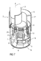
- Figure 7 shows an exemplary embodiment of a needle assembly magazine 2 according to the present invention after use.
- Figure 9 shows an exemplary embodiment of a needle assembly magazine 2 according to the present invention being prepared for a subsequent injection.
- the grip features may be used to rotate the needle assembly carrier 7 relative to the boss 12 to align a new needle assembly 8 with the distal apertures of the coupling 9 and the needle guard 10.
- Figures 8 and 10 show exemplary embodiments of a needle assembly magazine 2 according to the present invention being prepared for a subsequent injection.
- the needle assembly carrier 7 is being rotated relative to the boss 12 to align a new needle assembly 8 with the distal apertures of the coupling 9 and the needle guard 10.
- Engagement of the ratchets 15 and the resilient radial arm 14 provide a tactile feedback to the user.
- rotational resistance may increase as a ratchet 15 engages and deflects the radial arm 14.
- the rotational resistance may decrease providing a tactile feedback that the new needle assembly 8 is in a proper position.
- the radial arm 14 may prevent "rewinding" of the needle assembly carrier 7 so that a used needle assembly 8 is not reused.
- Figure 11 shows another exemplary embodiment of a needle assembly magazine according to the present invention.
- the housing 6 includes a cut-out 16 for viewing an indicia (e.g., a number, a graphic, a symbol, a color) indicating a number of unused needle assemblies remaining, a number of used needle assemblies, etc.
- an indicia e.g., a number, a graphic, a symbol, a color
- the indicia may be updated to provide a visual feedback regarding use of the needle assembly magazine.
- Figure 12 shows another exemplary embodiment of a needle assembly magazine according to the present invention.
- the needle assembly magazine 2 includes a needle assembly carrier 7 comprising a proximal plate 25 and a distal plate 24 which are both rotatably coupled to a boss 12.
- the proximal plate 25 is also slidably coupled to the boss 12.
- a carrier spring 26 biases the proximal plate 25 relative to the distal plate 24.
- the proximal plate 25 and the distal plate 24 include apertures for holding needle assemblies 8.
- the needle assemblies 8 each include a needle hub 17 coupled to a needle 8' having a proximal tip and a distal tip.
- the needle assembly magazine 2 includes a button 23 slidably coupled to the housing 6.
- the button 23 includes an external surface adapted to be pressed by a user.
- Clips 13 on the boss 12 engage the button 23 for movement of the button 23 relative to the boss 12 beyond an extended position (shown in Figure 12 ).
- a button spring 29 biases the button 23 toward the extended position.
- the button 23 is coupled to the proximal plate 25 so that pressing the button 23 into a retracted position displaces the proximal plate 25 relative to the boss 12.
- the housing 6 includes a drive tooth 27 adapted to engage a track 28 coupled to the proximal plate 25.
- the track 28 may be formed on a stem which extends proximally of the proximal plate 25, and the drive tooth 27 may be disposed radially on the housing 6 to engage the track 28.
- the track 28 comprises a number of longitudinal channels 28.1 adapted to receive the drive tooth 27. When the drive tooth 27 is in a longitudinal channel 28.1, rotation of the proximal plate 25 relative to the needle guard 10 is prevented.
- the track 28 further comprises a number of angled portions 28.2 which connect consecutive longitudinal channels 28.1.
- a angular space between consecutive longitudinal channels 28.1 corresponds to an angular space between consecutive needle assemblies 8 in the plates 24, 25, such that one depression of the button 23 causes rotation of the plates 24, 25 to align a needle assembly 8 with the distal apertures in the coupling 9 and the needle guard 10.
- the needle assembly magazine 2 is in a pre-use position.
- the medicament delivery device 2 is coupled to the housing 6, the needle guard 10 is in the extended position, and the button 23 is in the extended position.
- the needle guard 10 is maintained in the extended position, because the carrier spring 26 biases the plates 24, 25 relative to each other, and the proximal plate 25 abuts the housing 6 while the distal plate 24 abuts the needle guard 10.
- the housing 6 and the needle guard 10 may be made from an opaque material so that the needle 8' is never visible before, during or after use.
- all or a portion of the housing 6 and/or the needle guard 10 may be translucent to allow visualization of the needle 8' and/or any other internal component of the needle assembly magazine 2.
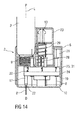
- Figure 14 shows an exemplary embodiment of a needle assembly magazine 2 during use.
- the distal aperture 22 is aligned with the injection site.
- a distally directed force is applied to the medicament delivery device 1 which causes the needle guard 10 to translate from the extended position toward the retracted position against the force of the carrier spring 26, causing the distal plate 24 to move axially toward the proximal plate 25.
- the coupling 9 engages the proximal flange on the needle assembly hub 17 and pushing the needle hub 17 (and the needle 8) in the distal direction from the retracted position to the extended position, such that the distal tip of the needle 8' passes through the distal aperture 22 of the needle guard 10 and pierces the injection site.
- the biasing force of the carrier spring 26 causes the needle distal plate 24 to translate in the distal direction, which causes the needle guard 10 to translate from the retracted position to the extended position. In the extended position, the needle guard 10 covers the distal tip of the needle 8'.
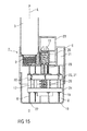
- Figure 15 shows an exemplary embodiment of a needle assembly magazine 2 according to the present invention being prepared for a subsequent injection.
- the button 23 is pressed to displace the proximal plate 25.
- the proximal plate 25 moves, it pushes the distal plate 24 in the distal direction via the carrier spring 26. This distal movement pulls the proximal tip of the needle 8' out of the cartridge 4 and the septum 5.
- Figure 16 shows an exemplary embodiment of a needle assembly magazine 2 according to the present invention being prepared for a subsequent injection.
- the drive tooth 27 travels proximally within a first longitudinal channel 28.1.
- the proximal plate 25, and thus the needle assemblies 8 and the distal plate 24 rotate relative to the housing 6 and the needle guard 10.
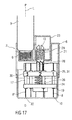
- Figure 17 shows an exemplary embodiment of a needle assembly magazine 2 according to the present invention being prepared for a subsequent injection.
- the drive tooth 27 has entered or aligned with a second longitudinal channel 28.1, and the plates 24, 25 have rotated a sufficient angular distance such that a new needle assembly is aligned with the distal apertures in the coupling 9 and the needle guard 10.
- Figure 18 shows an exemplary embodiment of a needle assembly magazine 2 according to the present invention being prepared for a subsequent injection.
- a new indicia 30 is visible to provide a visual feedback about, for example, the number of unused needle assemblies 8 remaining, the number of needle assemblies 8 which have been used, whether all of the needle assemblies have been used, etc.
Priority Applications (7)
| Application Number | Priority Date | Filing Date | Title |
|---|---|---|---|
| EP12196101.5A EP2740503A1 (fr) | 2012-12-07 | 2012-12-07 | Chargeur d'assemblage d'aiguille |
| CN201380071600.0A CN104955501B (zh) | 2012-12-07 | 2013-11-29 | 针组件盒 |
| JP2015545751A JP6363091B2 (ja) | 2012-12-07 | 2013-11-29 | ニードルアセンブリマガジン |
| EP13802007.8A EP2928518B1 (fr) | 2012-12-07 | 2013-11-29 | Chargeur d'assemblage d'aiguille |
| US14/650,158 US9889249B2 (en) | 2012-12-07 | 2013-11-29 | Needle assembly magazine |
| PCT/EP2013/075135 WO2014086684A1 (fr) | 2012-12-07 | 2013-11-29 | Chargeur d'ensemble aiguille |
| HK15112147.0A HK1211252A1 (en) | 2012-12-07 | 2015-12-09 | Needle assembly magazine |
Applications Claiming Priority (1)
| Application Number | Priority Date | Filing Date | Title |
|---|---|---|---|
| EP12196101.5A EP2740503A1 (fr) | 2012-12-07 | 2012-12-07 | Chargeur d'assemblage d'aiguille |
Publications (1)
| Publication Number | Publication Date |
|---|---|
| EP2740503A1 true EP2740503A1 (fr) | 2014-06-11 |
Family
ID=47602868
Family Applications (2)
| Application Number | Title | Priority Date | Filing Date |
|---|---|---|---|
| EP12196101.5A Ceased EP2740503A1 (fr) | 2012-12-07 | 2012-12-07 | Chargeur d'assemblage d'aiguille |
| EP13802007.8A Not-in-force EP2928518B1 (fr) | 2012-12-07 | 2013-11-29 | Chargeur d'assemblage d'aiguille |
Family Applications After (1)
| Application Number | Title | Priority Date | Filing Date |
|---|---|---|---|
| EP13802007.8A Not-in-force EP2928518B1 (fr) | 2012-12-07 | 2013-11-29 | Chargeur d'assemblage d'aiguille |
Country Status (6)
| Country | Link |
|---|---|
| US (1) | US9889249B2 (fr) |
| EP (2) | EP2740503A1 (fr) |
| JP (1) | JP6363091B2 (fr) |
| CN (1) | CN104955501B (fr) |
| HK (1) | HK1211252A1 (fr) |
| WO (1) | WO2014086684A1 (fr) |
Cited By (1)
| Publication number | Priority date | Publication date | Assignee | Title |
|---|---|---|---|---|
| US20180339108A1 (en) * | 2015-11-27 | 2018-11-29 | Sanofi-Aventis Deutschland Gmbh | Medicament injection device |
Families Citing this family (18)
| Publication number | Priority date | Publication date | Assignee | Title |
|---|---|---|---|---|
| WO2016041870A1 (fr) * | 2014-09-15 | 2016-03-24 | Sanofi | Dispositif d'administration de médicament avec boîtier rotatif sur une base |
| EP3448347A4 (fr) | 2016-04-28 | 2019-10-30 | Becton, Dickinson and Company | Système d'échange d'aiguille de stylo |
| WO2017189165A1 (fr) * | 2016-04-28 | 2017-11-02 | Becton, Dickinson And Company | Magasin d'aiguilles de stylo |
| EP3448477A4 (fr) * | 2016-04-28 | 2019-10-02 | Becton, Dickinson and Company | Magasin d'aiguilles de stylo |
| EP3448475B1 (fr) * | 2016-04-28 | 2022-07-13 | Embecta Corp. | Magasin pour aiguilles de stylo |
| EP3448478A4 (fr) * | 2016-04-28 | 2019-10-23 | Becton, Dickinson and Company | Système d'échange d'aiguilles de stylo |
| WO2017189170A1 (fr) | 2016-04-28 | 2017-11-02 | Becton, Dickinson And Company | Magasin d'aiguilles de stylo |
| CA3019344A1 (fr) | 2016-04-28 | 2017-11-02 | Becton, Dickinson And Company | Chargeur d'aiguilles de stylo |
| WO2017189162A1 (fr) * | 2016-04-28 | 2017-11-02 | Becton, Dickinson And Company | Magasin d'aiguilles de stylo |
| EP3448454A4 (fr) | 2016-04-28 | 2019-10-23 | Becton, Dickinson and Company | Magasin de stockage d'aiguilles avec indication d'état |
| CN109069729B (zh) | 2016-04-28 | 2021-08-20 | 贝克顿·迪金森公司 | 笔针仓 |
| KR102236251B1 (ko) * | 2018-02-28 | 2021-04-05 | 한국전자통신연구원 | 모듈형 자동 모발이식장치 |
| WO2020120086A1 (fr) * | 2018-12-13 | 2020-06-18 | Shl Medical Ag | Agencement pour supporter des dispositifs d'administration de médicament, et système |
| US20220249766A1 (en) * | 2019-04-26 | 2022-08-11 | Becton, Dickinson And Company | Pen assembly |
| WO2021165250A1 (fr) | 2020-02-18 | 2021-08-26 | Novo Nordisk A/S | Dispositif d'injection ayant des aiguilles intégrées |
| JP2024506741A (ja) | 2021-02-18 | 2024-02-14 | ノボ・ノルデイスク・エー/エス | 所定の固定用量を送達するための薬剤送達装置 |
| WO2022175242A1 (fr) | 2021-02-18 | 2022-08-25 | Novo Nordisk A/S | Dispositif d'administration de médicament pour l'administration d'une dose fixe prédéfinie |
| JP2024510093A (ja) * | 2021-02-18 | 2024-03-06 | ノボ・ノルデイスク・エー/エス | 所定の固定用量を送達するための薬剤送達装置 |
Citations (3)
| Publication number | Priority date | Publication date | Assignee | Title |
|---|---|---|---|---|
| WO2001093927A1 (fr) * | 2000-06-09 | 2001-12-13 | Novo Nordisk A/S | Chargeur d'aiguilles |
| WO2004110299A2 (fr) * | 2003-06-17 | 2004-12-23 | Adst Technologies Ltd. | Dispositif de transfert de fluide comportant une cartouche d'aiguilles amovible |
| US20080312604A1 (en) * | 2007-06-12 | 2008-12-18 | Boesen Peter V | Self-contained medication injection system and method |
Family Cites Families (5)
| Publication number | Priority date | Publication date | Assignee | Title |
|---|---|---|---|---|
| EP2185225A1 (fr) * | 2007-07-28 | 2010-05-19 | Novo Nordisk A/S | Magasin à aiguilles |
| WO2010048753A1 (fr) * | 2008-10-29 | 2010-05-06 | Pan Qiubao | Seringue à injection continue avec changement d’aiguille automatique |
| US9107988B2 (en) * | 2010-08-16 | 2015-08-18 | Becton, Dickinson And Company | Circuitous band needle changing apparatus |
| US9381303B2 (en) * | 2010-08-16 | 2016-07-05 | Becton, Dickinson And Company | Sterility barrier for pen needle and storage container therefor |
| EP2827920B1 (fr) * | 2012-03-22 | 2016-04-06 | Novo Nordisk A/S | Magasin à aiguilles rotatif |
-
2012
- 2012-12-07 EP EP12196101.5A patent/EP2740503A1/fr not_active Ceased
-
2013
- 2013-11-29 US US14/650,158 patent/US9889249B2/en not_active Expired - Fee Related
- 2013-11-29 JP JP2015545751A patent/JP6363091B2/ja not_active Expired - Fee Related
- 2013-11-29 WO PCT/EP2013/075135 patent/WO2014086684A1/fr active Application Filing
- 2013-11-29 CN CN201380071600.0A patent/CN104955501B/zh not_active Expired - Fee Related
- 2013-11-29 EP EP13802007.8A patent/EP2928518B1/fr not_active Not-in-force
-
2015
- 2015-12-09 HK HK15112147.0A patent/HK1211252A1/xx not_active IP Right Cessation
Patent Citations (3)
| Publication number | Priority date | Publication date | Assignee | Title |
|---|---|---|---|---|
| WO2001093927A1 (fr) * | 2000-06-09 | 2001-12-13 | Novo Nordisk A/S | Chargeur d'aiguilles |
| WO2004110299A2 (fr) * | 2003-06-17 | 2004-12-23 | Adst Technologies Ltd. | Dispositif de transfert de fluide comportant une cartouche d'aiguilles amovible |
| US20080312604A1 (en) * | 2007-06-12 | 2008-12-18 | Boesen Peter V | Self-contained medication injection system and method |
Cited By (3)
| Publication number | Priority date | Publication date | Assignee | Title |
|---|---|---|---|---|
| US20180339108A1 (en) * | 2015-11-27 | 2018-11-29 | Sanofi-Aventis Deutschland Gmbh | Medicament injection device |
| US11147923B2 (en) * | 2015-11-27 | 2021-10-19 | Sanofi-Aventis Deutschland Gmbh | Medicament injection device |
| US20220001107A1 (en) * | 2015-11-27 | 2022-01-06 | Sanofi-Aventis Deutschland Gmbh | Medicament injection device |
Also Published As
| Publication number | Publication date |
|---|---|
| JP2015536222A (ja) | 2015-12-21 |
| EP2928518B1 (fr) | 2018-03-21 |
| EP2928518A1 (fr) | 2015-10-14 |
| WO2014086684A1 (fr) | 2014-06-12 |
| JP6363091B2 (ja) | 2018-07-25 |
| US20160000992A1 (en) | 2016-01-07 |
| CN104955501B (zh) | 2018-06-01 |
| HK1211252A1 (en) | 2016-05-20 |
| US9889249B2 (en) | 2018-02-13 |
| CN104955501A (zh) | 2015-09-30 |
Similar Documents
| Publication | Publication Date | Title |
|---|---|---|
| US9889249B2 (en) | Needle assembly magazine | |
| JP6426399B2 (ja) | 安全な充填済みペンニードル | |
| JP6367986B2 (ja) | 針交換装置 | |
| JP4298511B2 (ja) | ペン針及び安全シールドシステム | |
| CA2748784C (fr) | Dispositif de remplacement d'aiguille amovible pour dispositif d'administration de medicaments | |
| EP2572745A1 (fr) | Dispositif de sécurité d'aiguille | |
| US20150283333A1 (en) | Needle assembly magazine | |
| US10603444B2 (en) | Automatic injection device with variable dosing | |
| EP2596825A1 (fr) | Dispositif de fixation et de retrait d'un ensemble formant aiguille | |
| JP6297507B2 (ja) | ニードルアセンブリ取外しデバイスおよび処分デバイス | |
| EP2714154A1 (fr) | Dispositif de retrait d'ensemble aiguille | |
| EP2559447A1 (fr) | Ensemble formant aiguille à usage unique et dispositif de stockage | |
| WO2008118101A1 (fr) | Garde de sécurité pour aiguille de seringue |
Legal Events
| Date | Code | Title | Description |
|---|---|---|---|
| PUAI | Public reference made under article 153(3) epc to a published international application that has entered the european phase |
Free format text: ORIGINAL CODE: 0009012 |
|
| 17P | Request for examination filed |
Effective date: 20121207 |
|
| AK | Designated contracting states |
Kind code of ref document: A1 Designated state(s): AL AT BE BG CH CY CZ DE DK EE ES FI FR GB GR HR HU IE IS IT LI LT LU LV MC MK MT NL NO PL PT RO RS SE SI SK SM TR |
|
| AX | Request for extension of the european patent |
Extension state: BA ME |
|
| STAA | Information on the status of an ep patent application or granted ep patent |
Free format text: STATUS: THE APPLICATION HAS BEEN REFUSED |
|
| 18R | Application refused |
Effective date: 20140630 |