EP2738507A1 - Heat exchanger - Google Patents
Heat exchanger Download PDFInfo
- Publication number
- EP2738507A1 EP2738507A1 EP12817270.7A EP12817270A EP2738507A1 EP 2738507 A1 EP2738507 A1 EP 2738507A1 EP 12817270 A EP12817270 A EP 12817270A EP 2738507 A1 EP2738507 A1 EP 2738507A1
- Authority
- EP
- European Patent Office
- Prior art keywords
- refrigerant
- channel
- tube
- heat exchanger
- flat
- Prior art date
- Legal status (The legal status is an assumption and is not a legal conclusion. Google has not performed a legal analysis and makes no representation as to the accuracy of the status listed.)
- Granted
Links
Images




Classifications
-
- F—MECHANICAL ENGINEERING; LIGHTING; HEATING; WEAPONS; BLASTING
- F28—HEAT EXCHANGE IN GENERAL
- F28D—HEAT-EXCHANGE APPARATUS, NOT PROVIDED FOR IN ANOTHER SUBCLASS, IN WHICH THE HEAT-EXCHANGE MEDIA DO NOT COME INTO DIRECT CONTACT
- F28D7/00—Heat-exchange apparatus having stationary tubular conduit assemblies for both heat-exchange media, the media being in contact with different sides of a conduit wall
- F28D7/0008—Heat-exchange apparatus having stationary tubular conduit assemblies for both heat-exchange media, the media being in contact with different sides of a conduit wall the conduits for one medium being in heat conductive contact with the conduits for the other medium
- F28D7/0025—Heat-exchange apparatus having stationary tubular conduit assemblies for both heat-exchange media, the media being in contact with different sides of a conduit wall the conduits for one medium being in heat conductive contact with the conduits for the other medium the conduits for one medium or the conduits for both media being flat tubes or arrays of tubes
- F28D7/0033—Heat-exchange apparatus having stationary tubular conduit assemblies for both heat-exchange media, the media being in contact with different sides of a conduit wall the conduits for one medium being in heat conductive contact with the conduits for the other medium the conduits for one medium or the conduits for both media being flat tubes or arrays of tubes the conduits for one medium or the conduits for both media being bent
-
- F—MECHANICAL ENGINEERING; LIGHTING; HEATING; WEAPONS; BLASTING
- F28—HEAT EXCHANGE IN GENERAL
- F28F—DETAILS OF HEAT-EXCHANGE AND HEAT-TRANSFER APPARATUS, OF GENERAL APPLICATION
- F28F1/00—Tubular elements; Assemblies of tubular elements
- F28F1/02—Tubular elements of cross-section which is non-circular
- F28F1/022—Tubular elements of cross-section which is non-circular with multiple channels
-
- F—MECHANICAL ENGINEERING; LIGHTING; HEATING; WEAPONS; BLASTING
- F28—HEAT EXCHANGE IN GENERAL
- F28F—DETAILS OF HEAT-EXCHANGE AND HEAT-TRANSFER APPARATUS, OF GENERAL APPLICATION
- F28F1/00—Tubular elements; Assemblies of tubular elements
- F28F1/02—Tubular elements of cross-section which is non-circular
- F28F1/025—Tubular elements of cross-section which is non-circular with variable shape, e.g. with modified tube ends, with different geometrical features
-
- F—MECHANICAL ENGINEERING; LIGHTING; HEATING; WEAPONS; BLASTING
- F28—HEAT EXCHANGE IN GENERAL
- F28F—DETAILS OF HEAT-EXCHANGE AND HEAT-TRANSFER APPARATUS, OF GENERAL APPLICATION
- F28F9/00—Casings; Header boxes; Auxiliary supports for elements; Auxiliary members within casings
- F28F9/02—Header boxes; End plates
- F28F9/0219—Arrangements for sealing end plates into casing or header box; Header box sub-elements
- F28F9/0221—Header boxes or end plates formed by stacked elements
-
- F—MECHANICAL ENGINEERING; LIGHTING; HEATING; WEAPONS; BLASTING
- F28—HEAT EXCHANGE IN GENERAL
- F28F—DETAILS OF HEAT-EXCHANGE AND HEAT-TRANSFER APPARATUS, OF GENERAL APPLICATION
- F28F9/00—Casings; Header boxes; Auxiliary supports for elements; Auxiliary members within casings
- F28F9/02—Header boxes; End plates
- F28F9/0243—Header boxes having a circular cross-section
-
- F—MECHANICAL ENGINEERING; LIGHTING; HEATING; WEAPONS; BLASTING
- F28—HEAT EXCHANGE IN GENERAL
- F28F—DETAILS OF HEAT-EXCHANGE AND HEAT-TRANSFER APPARATUS, OF GENERAL APPLICATION
- F28F9/00—Casings; Header boxes; Auxiliary supports for elements; Auxiliary members within casings
- F28F9/02—Header boxes; End plates
- F28F9/026—Header boxes; End plates with static flow control means, e.g. with means for uniformly distributing heat exchange media into conduits
- F28F9/0278—Header boxes; End plates with static flow control means, e.g. with means for uniformly distributing heat exchange media into conduits in the form of stacked distribution plates or perforated plates arranged over end plates
-
- F—MECHANICAL ENGINEERING; LIGHTING; HEATING; WEAPONS; BLASTING
- F25—REFRIGERATION OR COOLING; COMBINED HEATING AND REFRIGERATION SYSTEMS; HEAT PUMP SYSTEMS; MANUFACTURE OR STORAGE OF ICE; LIQUEFACTION SOLIDIFICATION OF GASES
- F25B—REFRIGERATION MACHINES, PLANTS OR SYSTEMS; COMBINED HEATING AND REFRIGERATION SYSTEMS; HEAT PUMP SYSTEMS
- F25B1/00—Compression machines, plants or systems with non-reversible cycle
- F25B1/10—Compression machines, plants or systems with non-reversible cycle with multi-stage compression
-
- F—MECHANICAL ENGINEERING; LIGHTING; HEATING; WEAPONS; BLASTING
- F25—REFRIGERATION OR COOLING; COMBINED HEATING AND REFRIGERATION SYSTEMS; HEAT PUMP SYSTEMS; MANUFACTURE OR STORAGE OF ICE; LIQUEFACTION SOLIDIFICATION OF GASES
- F25B—REFRIGERATION MACHINES, PLANTS OR SYSTEMS; COMBINED HEATING AND REFRIGERATION SYSTEMS; HEAT PUMP SYSTEMS
- F25B2400/00—Component parts or details not otherwise provided for in this subclass
- F25B2400/13—Economisers
-
- F—MECHANICAL ENGINEERING; LIGHTING; HEATING; WEAPONS; BLASTING
- F28—HEAT EXCHANGE IN GENERAL
- F28D—HEAT-EXCHANGE APPARATUS, NOT PROVIDED FOR IN ANOTHER SUBCLASS, IN WHICH THE HEAT-EXCHANGE MEDIA DO NOT COME INTO DIRECT CONTACT
- F28D1/00—Heat-exchange apparatus having stationary conduit assemblies for one heat-exchange medium only, the media being in contact with different sides of the conduit wall, in which the other heat-exchange medium is a large body of fluid, e.g. domestic or motor car radiators
- F28D1/02—Heat-exchange apparatus having stationary conduit assemblies for one heat-exchange medium only, the media being in contact with different sides of the conduit wall, in which the other heat-exchange medium is a large body of fluid, e.g. domestic or motor car radiators with heat-exchange conduits immersed in the body of fluid
- F28D1/04—Heat-exchange apparatus having stationary conduit assemblies for one heat-exchange medium only, the media being in contact with different sides of the conduit wall, in which the other heat-exchange medium is a large body of fluid, e.g. domestic or motor car radiators with heat-exchange conduits immersed in the body of fluid with tubular conduits
- F28D1/0408—Multi-circuit heat exchangers, e.g. integrating different heat exchange sections in the same unit or heat exchangers for more than two fluids
- F28D1/0426—Multi-circuit heat exchangers, e.g. integrating different heat exchange sections in the same unit or heat exchangers for more than two fluids with units having particular arrangement relative to the large body of fluid, e.g. with interleaved units or with adjacent heat exchange units in common air flow or with units extending at an angle to each other or with units arranged around a central element
-
- F—MECHANICAL ENGINEERING; LIGHTING; HEATING; WEAPONS; BLASTING
- F28—HEAT EXCHANGE IN GENERAL
- F28D—HEAT-EXCHANGE APPARATUS, NOT PROVIDED FOR IN ANOTHER SUBCLASS, IN WHICH THE HEAT-EXCHANGE MEDIA DO NOT COME INTO DIRECT CONTACT
- F28D1/00—Heat-exchange apparatus having stationary conduit assemblies for one heat-exchange medium only, the media being in contact with different sides of the conduit wall, in which the other heat-exchange medium is a large body of fluid, e.g. domestic or motor car radiators
- F28D1/02—Heat-exchange apparatus having stationary conduit assemblies for one heat-exchange medium only, the media being in contact with different sides of the conduit wall, in which the other heat-exchange medium is a large body of fluid, e.g. domestic or motor car radiators with heat-exchange conduits immersed in the body of fluid
- F28D1/04—Heat-exchange apparatus having stationary conduit assemblies for one heat-exchange medium only, the media being in contact with different sides of the conduit wall, in which the other heat-exchange medium is a large body of fluid, e.g. domestic or motor car radiators with heat-exchange conduits immersed in the body of fluid with tubular conduits
- F28D1/053—Heat-exchange apparatus having stationary conduit assemblies for one heat-exchange medium only, the media being in contact with different sides of the conduit wall, in which the other heat-exchange medium is a large body of fluid, e.g. domestic or motor car radiators with heat-exchange conduits immersed in the body of fluid with tubular conduits the conduits being straight
- F28D1/0535—Heat-exchange apparatus having stationary conduit assemblies for one heat-exchange medium only, the media being in contact with different sides of the conduit wall, in which the other heat-exchange medium is a large body of fluid, e.g. domestic or motor car radiators with heat-exchange conduits immersed in the body of fluid with tubular conduits the conduits being straight the conduits having a non-circular cross-section
- F28D1/05366—Assemblies of conduits connected to common headers, e.g. core type radiators
- F28D1/05383—Assemblies of conduits connected to common headers, e.g. core type radiators with multiple rows of conduits or with multi-channel conduits
Definitions
- the present invention relates to a heat exchanger.
- Heat exchangers that use flat porous tubes to allow heat exchange between a refrigerant and a refrigerant are conventionally used in refrigeration cycles, as disclosed in Patent Document 1 (Japanese Laid-Open Patent Application No. 2007-163004 ).
- Two flat porous tubes, through which flow two respective types of refrigerant that are subjected to heat exchange, are bonded together in these heat exchangers.
- the flat porous tubes in these heat exchangers are linked to a header so that the alignment direction of refrigerant flow-channel holes of the flat porous tubes proceeds along a longitudinal direction of the header.
- the header must therefore be lengthened in cases where a plurality of the flat porous tubes are linked to the header, and the device is not readily made more compact.
- a heat exchanger comprises a header, a first flat tube, and a second flat tube.
- the header has a first primary channel and a second primary channel, a first refrigerant flowing through the first primary channel, and a second refrigerant flowing through the second primary channel.
- the first flat tube is linked to the header.
- the first flat tube is a flat porous tube that has a plurality of first refrigerant-channel holes through which the first refrigerant flows.
- the second flat tube is linked to the header.
- the second flat tube is a flat porous tube that has a plurality of second refrigerant-channel holes through which the second refrigerant flows.
- the header has a sub-channel-forming member.
- the sub-channel-forming member forms a first sub-channel and a second sub-channel.
- the first sub-channel allows the first primary channel to be communicated with the first refrigerant-channel holes.
- the second sub-channel allows the second primary channel to be communicated with the second refrigerant-channel holes.
- the first flat tube and the second flat tube are in close contact. In the first flat tube and the second flat tube, heat is exchanged between the first refrigerant flowing through the first refrigerant-channel holes and the second refrigerant flowing through the second refrigerant-channel holes.
- the first primary channel of the header is communicated with the plurality of the first refrigerant-channel holes of the first flat tube via the first sub-channel
- the second primary channel of the header is communicated with the plurality of the second refrigerant-channel holes of the second flat tube via the second sub-channel.
- the first flat tube is flat along the alignment direction of the first refrigerant-channel holes.
- the first primary channel is formed along a longitudinal direction of the header. In cases where the first refrigerant-channel holes are directly communicated with the first primary channel, the first flat tube must be linked to the header so that the flatness direction of the first flat tube proceeds along the longitudinal direction of the header.
- the header must therefore be long in cases where a plurality of the first flat tubes are linked to the header, and therefore the heat exchanger is not readily made more compact.
- the refrigerant-channel holes are communicated with the first primary channel via the first sub-channel, whereby the first flat tube need not be linked to the header so that the flatness direction of the first flat tube proceeds along the longitudinal direction of the header.
- the case is the same for the second flat tube. Therefore, the header does not need to be lengthened, and the heat exchanger according to the first aspect can be made more compact.
- a heat exchanger according to a second aspect of the present invention is the heat exchanger according to the first aspect, wherein the first flat tube and the second flat tube are linked to the header so that a cross-sectional longitudinal direction intersects a longitudinal direction of the header, the cross-sectional longitudinal direction being alignment directions of the first refrigerant-channel holes and the second refrigerant-channel holes.
- a heat exchanger according to a third aspect of the present invention is the heat exchanger according to the second aspect, wherein the first flat tube and the second flat tube are linked to the header so that the cross-sectional longitudinal direction is perpendicular to the longitudinal direction of the header.
- the first flat tube is linked to the header so that the flatness direction of the first flat tube is perpendicular to the longitudinal direction of the header.
- the case is the same for the second flat tube.
- the heat exchanger according to the third aspect can therefore be efficiently made more compact.
- a heat exchanger according to a fourth aspect of the present invention is the heat exchanger according to any of the first through third aspects, wherein the sub-channel-forming member comprises a tube-adhering member adhered to end parts of the first flat tube and the second flat tube and immobilized on the header.
- a member for linking the first flat tube to the header and a member for linking the second flat tube to the header can be integrated.
- the number of components can therefore be minimized in the heat exchanger according to the fourth aspect, and manufacturing costs can therefore be limited.
- a heat exchanger according to a fifth aspect of the present invention is the heat exchanger according to the fourth aspect, wherein the sub-channel-forming member further comprises a tube-immobilizing member for immobilizing the end parts of the first flat tube and the second flat tube along with the tube-adhering member.
- a heat exchanger according to a sixth aspect of the present invention is the heat exchanger according to any of the first through fifth aspects, wherein the sub-channel-forming member forms a plurality of the first sub-channels and a plurality of the second sub-channels.
- a heat exchanger according to a seventh aspect of the present invention is the heat exchanger according to any of the first through sixth aspects, wherein the first refrigerant and the second refrigerant are carbon dioxide.
- the heat exchanger according to the first through seventh aspects of the present invention can be made more compact.
- the manufacturing costs of the heat exchanger according to the fourth through sixth aspects of the present invention can be limited.
- FIG. 1 is a schematic diagram of an air-conditioning device 1 that serves as an example of a refrigerating device provided with a heat exchanger according to the present invention.
- the air-conditioning device 1 has a refrigerant circuit 10 configured so as to allow air-cooling operations, uses carbon dioxide or another refrigerant active in the supercritical region, and performs a two-stage compression refrigeration cycle.
- the refrigerant circuit 10 primarily has a compression mechanism 2, a heat-source-side heat exchanger 3, an expansion mechanism 4, a usage-side heat exchanger 5, and an economizer heat exchanger 6. These components will be described next.
- the compression mechanism 2 compresses refrigerant from a low pressure in the refrigeration cycle to a high pressure in the refrigeration cycle.
- the compression mechanism 2 is a compressor 21 that uses two compression elements and compresses the refrigerant in two stages.
- the compressor 21 has an airtight structure that accommodates a compression-element-driving motor 21b, a drive shaft 21c, a first-stage compression element 2c, and a second-stage compression element 2d in a casing 21a.
- the compression-element-driving motor 21b is linked to the drive shaft 21c.
- the drive shaft 21c is linked to the first-stage compression element 2c and the second-stage compression element 2d.
- the compressor 21 has a uniaxial two-stage compression structure in which the compression-element-driving motor 21b drives the first-stage compression element 2c and the second-stage compression element 2d via the single drive shaft 21 c.
- the compressor 21 takes in low-pressure refrigerant from an intake tube 2a, uses the first-stage compression element 2c to compress the refrigerant taken in, and then discharges compressed intermediate-pressure refrigerant to an intermediate-pressure-refrigerant tube 7.
- the compressor 21 then takes in the intermediate-pressure refrigerant discharged to the intermediate-pressure-refrigerant tube 7, uses the second-stage compression element 2d to compress the refrigerant taken in, and then discharges the compressed high-pressure refrigerant to a discharge tube 2b.
- the heat-source-side heat exchanger 3 is a radiator for cooling the high-pressure refrigerant compressed by the compression mechanism 2.
- the heat-source-side heat exchanger 3 causes heat exchange between air, which acts as a coolant source, and the refrigerant flowing within the heat-source-side heat exchanger 3.
- the heat-source-side heat exchanger 3 is connected to the compression mechanism 2 via a first high-pressure refrigerant tube 3a and the discharge tube 2b.
- the first high-pressure refrigerant tube 3a is connected to an inlet of the heat-source-side heat exchanger 3 and to the discharge tube 2b.
- the heat-source-side heat exchanger 3 is connected to the economizer heat exchanger 6 and an injection part 8, which will be described hereinafter, via a second high-pressure refrigerant tube 3b.
- the second high-pressure refrigerant tube 3b is connected to an outlet of the heat-source-side heat exchanger 3, to an inlet of the economizer heat exchanger 6 (an inlet of a channel for refrigerant sent from the heat-source-side heat exchanger 3 to the expansion mechanism 4) and to an inlet of the injection part 8 (an inlet of a channel for refrigerant diverted from the second high-pressure refrigerant tube 3b).
- the expansion mechanism 4 decompresses the high-pressure refrigerant, which was cooled in the heat-source-side heat exchanger 3 and the economizer heat exchanger 6, to near the low pressure of the refrigeration cycle before sending the refrigerant to the usage-side heat exchanger 5.
- the expansion mechanism 4 is, e.g., an electrically operated expansion valve.
- the expansion mechanism 4 is connected to the economizer heat exchanger 6 via a third high-pressure refrigerant tube 3c.
- the third high-pressure refrigerant tube 3c is connected to an outlet of the economizer heat exchanger 6 (an outlet of a channel for refrigerant sent from the heat-source-side heat exchanger 3 to the expansion mechanism 4) and to an inlet of the expansion mechanism 4.
- the expansion mechanism 4 is connected to the usage-side heat exchanger 5 via a first low-pressure refrigerant tube 5a.
- the first low-pressure refrigerant tube 5a is connected to an outlet of the expansion mechanism 4 and to an inlet of the usage-side heat exchanger 5.
- the usage-side heat exchanger 5 is an evaporator for heating and evaporating the low-pressure refrigerant that was decompressed by the expansion mechanism 4.
- the usage-side heat exchanger 5 causes heat exchange between air, which serves as a heat source, and the refrigerant flowing within the usage-side heat exchanger 5.
- the usage-side heat exchanger 5 is connected to the expansion mechanism 4 via the first low-pressure refrigerant tube 5a.
- the usage-side heat exchanger 5 is connected to the compression mechanism 2 via a second low-pressure refrigerant tube 5b.
- the second low-pressure refrigerant tube 5b is connected to an outlet of the usage-side heat exchanger 5 and to the intake tube 2a.
- the economizer heat exchanger 6 causes heat exchange between the high-pressure refrigerant sent from the heat-source-side heat exchanger 3 to the expansion mechanism 4 and the intermediate-pressure refrigerant flowing through the injection part 8.
- the injection part 8 diverts the high-pressure refrigerant flowing from the heat-source-side heat exchanger 3 to the expansion mechanism 4 and returns the refrigerant to the inlet of the second-stage compression element 2d. Specifically, the injection part 8 diverts refrigerant from the second high-pressure refrigerant tube 3b and returns the refrigerant to the intermediate-pressure-refrigerant tube 7.
- the injection part 8 comprises a first injection tube 8a and a second injection tube 8b.
- the first injection tube 8a connects the second high-pressure refrigerant tube 3b with an inlet of the economizer heat exchanger 6 (an inlet of a channel for refrigerant diverted from the second high-pressure refrigerant tube 3b).
- the second injection tube 8b connects an outlet of the economizer heat exchanger 6 (an outlet of a channel for refrigerant diverted from the second high-pressure refrigerant tube 3b) with the intermediate-pressure-refrigerant tube 7.
- An injection valve 8c that functions as a return valve having a controllable opening degree is provided to the first injection tube 8a.
- the injection valve 8c is, e.g., an electrically operated expansion valve.
- the injection valve 8c decompresses the high-pressure refrigerant diverted from the second high-pressure refrigerant tube 3b to around the intermediate pressure of the refrigerant flowing within the intermediate-pressure-refrigerant tube 7.
- the high-pressure refrigerant sent from the heat-source-side heat exchanger 3 to the expansion mechanism 4 is cooled by heat exchange with the intermediate-pressure refrigerant flowing through the injection part 8. Meanwhile, the intermediate-pressure refrigerant flowing through the injection part 8 is heated and evaporated by heat exchange with the high-pressure refrigerant, which is sent from the heat-source-side heat exchanger 3 to the expansion mechanism 4, while temporarily flowing in a gas-liquid two-phase state. After passing through the second injection tube 8b, the evaporated intermediate-pressure refrigerant merges with the refrigerant flowing through the intermediate-pressure-refrigerant tube 7.
- the action of the air-conditioning device 1 during air-cooling operations will be described next on the basis of the flow of refrigerant circulating through the refrigerant circuit 10.
- the refrigerant at the low pressure of the refrigeration cycle is taken in from the intake tube 2a to the compression mechanism 2.
- the low-pressure refrigerant taken in to the compression mechanism 2 is compressed to the intermediate pressure of the refrigeration cycle by the first-stage compression element 2c and then discharged to the intermediate-pressure-refrigerant tube 7.
- the intermediate-pressure refrigerant discharged from the first-stage compression element 2c is merged with the intermediate-pressure refrigerant returned from the second injection tube 8b.
- the merged intermediate-pressure refrigerant is taken in to the second-stage compression element 2d and compressed to the high pressure of the refrigeration cycle by the second-stage compression element 2d.
- the compressed high-pressure refrigerant is discharged from the compression mechanism 2 to the discharge tube 2b.
- the high-pressure refrigerant discharged from the compression mechanism 2 is sent through the first high-pressure refrigerant tube 3a to the heat-source-side heat exchanger 3.
- the high-pressure refrigerant sent to the heat-source-side heat exchanger 3 is subjected to heat exchange with outside air and cooled by the heat-source-side heat exchanger 3.
- a portion of the high-pressure refrigerant cooled by the heat-source-side heat exchanger 3 is diverted in the second high-pressure refrigerant tube 3b to the first injection tube 8a.
- the high-pressure refrigerant diverted to the first injection tube 8a is decompressed to around the intermediate pressure of the refrigeration cycle by the injection valve 8c and is then sent to the economizer heat exchanger 6. Meanwhile, the high-pressure refrigerant subsequent to the diversion to the first injection tube 8a (i.e., refrigerant flowing through the second high-pressure refrigerant tube 3b) is sent to the economizer heat exchanger 6.
- the high-pressure refrigerant from the second high-pressure refrigerant tube 3b is subjected to heat exchange with the intermediate-pressure refrigerant from the first injection tube 8a and cooled. Meanwhile, the intermediate-pressure refrigerant from the first injection tube 8a is subjected to heat exchange with the high-pressure refrigerant from the second high-pressure refrigerant tube 3b, heated, and returned through second injection tube 8b to the intermediate-pressure-refrigerant tube 7.
- the high-pressure refrigerant cooled in the economizer heat exchanger 6 is sent through the third high-pressure refrigerant tube 3c to the expansion mechanism 4.
- the high-pressure refrigerant sent to the expansion mechanism 4 is decompressed by the expansion mechanism 4, enters a gas-liquid two-phase state at the low pressure of the refrigeration cycle, and is sent through the first low-pressure refrigerant tube 5a to the usage-side heat exchanger 5.
- the low-pressure, gas-liquid two-phase refrigerant sent to the usage-side heat exchanger 5 is subjected to heat exchange with outside air, heated, and evaporated by the usage-side heat exchanger 5.
- the low-pressure refrigerant that was heated and evaporated by the usage-side heat exchanger 5 is once again taken in to the compression mechanism 2 through the second low-pressure refrigerant tube 5b and the intake tube 2a.
- the air-conditioning device 1 thus circulates refrigerant within the refrigerant circuit 10 and performs air-cooling operations.
- FIG. 2 is a front view of the economizer heat exchanger 6.
- FIG. 3 is a top view of the economizer heat exchanger 6.
- FIG. 2 is a front view from the direction of an arrow II shown in FIG. 3.
- FIG. 3 is a top view from the direction of an arrow III shown in FIG. 2 .
- FIGS. 4 and 5 are cross-sectional views in a horizontal direction cut along cut line IV-IV and cut line V-V, respectively, in FIG. 2 .
- the economizer heat exchanger 6 primarily comprises a pair of headers 61, a plurality of first flat porous tubes 64a, and a plurality of second flat porous tubes 64b. These components will be described next.
- the header 61 is positioned so that the longitudinal direction thereof proceeds along the vertical direction.
- the header 61 has a channel-forming member 62 and a tube-connecting member 63.
- the channel-forming member 62 has, therein, a first primary channel 62a1, a second primary channel 62a2, a plurality of first linking channels 62b1, and a plurality of second linking channels 62b2.
- the first linking channels 62b1 and the second linking channels 62b2 are communicated with the first primary channel 62a1 and the second primary channel 62a2, respectively, as shown in FIGS. 4 through 7 .
- FIG. 8 is an exterior view of the channel-forming member 62 seen from an arrow VIII in FIG. 4 .
- the first linking channels 62b1 and the second linking channels 62b2 open in alternation along the longitudinal direction of the channel-forming member 62 on an opening surface 62s of the channel-forming member 62, as shown in FIG. 8 .
- the first linking channels 62b1 open on the opening surface 62s along the first primary channel 62a1
- the second linking channels 62b2 open on the opening surface 62s along the second primary channel 62a2.
- the high-pressure refrigerant from the second high-pressure refrigerant tube 3b flows in the first primary channel 62a1 and the first linking channels 62b1.
- the intermediate-pressure refrigerant from the first injection tube 8a flows in the second primary channel 62a2 and the second linking channels 62b2.
- Refrigerant in the first primary channel 62a1 flows in the vertical direction, and refrigerant in the first linking channels 62b1 is diverted from the first primary channel 62a1 and flows in a horizontal direction.
- Refrigerant in the second primary channel 62a2 flows in the vertical direction, and refrigerant in the second linking channels 62b2 is diverted from the second primary channel 62a2 and flows in the horizontal direction.
- the tube-connecting member 63 connects the channel-forming member 62, the first flat porous tubes 64a, and the second flat porous tubes 64b.
- the detailed configuration of the tube-connecting member 63 will be described hereinafter.
- the first flat porous tubes 64a have a plurality of first refrigerant-channel holes 65a.
- the first flat porous tubes 64a are positioned so that the alignment direction of the first refrigerant-channel holes 65a is in the horizontal direction, i.e., so that the normal to the flat surface indicates the vertical direction.
- the second flat porous tubes 64b have a plurality of second refrigerant-channel holes 65b.
- the second flat porous tubes 64b are positioned so that the alignment direction of the second refrigerant-channel holes 65b is in the horizontal direction, i.e., so that the normal to the flat surface indicates the vertical direction.
- Pairs of a single one of the first flat porous tubes 64a and a single one of the second flat porous tubes 64b, which are brought into close contact at the flat surfaces, are positioned at a plurality of stages along the longitudinal direction of the header 61 in the present embodiment, as shown in FIG. 2 . Both end parts of the first flat porous tubes 64a and the second flat porous tubes 64b are linked respectively to the pair of the headers 61.
- FIG. 9 is a cross-sectional view of the first flat porous tubes 64a and the second flat porous tubes 64b cut along a cut line IX-IX in FIG. 3 .
- the alignment direction of the first refrigerant-channel holes 65a of the first flat porous tubes 64a and the alignment direction of the second refrigerant-channel holes 65b of the second flat porous tubes 64b are perpendicular to the longitudinal direction of the headers 61, as shown in FIG. 9 .
- the tube-connecting member 63 is configured from a tube-adhering member 63a, a tube-immobilizing member 63b, and a spacer member 63c, as shown in FIGS. 4 through 7 .
- FIG. 10 is a front view of the tube-adhering member 63a.
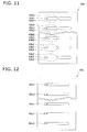
- FIG. 11 is a front view of the tube-immobilizing member 63b.
- FIG. 12 is a front view of the spacer member 63c.
- FIGS. 10 through 12 are all external views from an arrow VIII in FIG. 4 .
- the tube-adhering member 63a has a U-shaped cross-section when viewed along the vertical direction, as shown in FIGS. 4 through 7 .
- a plurality of flat-tube-fitting insertion holes 63a1 are positioned in the vertical direction, as shown in FIG. 10 .
- End parts of the first flat porous tubes 64a and the second flat porous tubes 64b are fit into the respective flat-tube-fitting insertion holes 63a1.
- the flat-tube-fitting insertion holes 63a1 immobilize the end parts of the first flat porous tubes 64a and the second flat porous tubes 64b.
- the tube-immobilizing member 63b is a plate-shaped member positioned in close contact with the tube-adhering member 63a and the spacer member 63c in a space surrounded by the tube-adhering member 63a and the channel-forming member 62, as shown in FIGS. 4 through 7 .
- a plurality of flat-tube-fastening holes 63b1 are positioned in the vertical direction in the tube-immobilizing member 63b, as shown in FIG. 11 .
- the flat-tube-fastening holes 63b1 have two convex parts 63b2 at a center part in the horizontal direction.
- the convex parts 63b2 immobilize the end parts of the first flat porous tubes 64a and the second flat porous tubes 64b.
- the height of the convex parts 63b2 is less than the thickness of the first flat porous tubes 64a and the second flat porous tubes 64b.
- the spacer member 63c is a plate-shaped member positioned in close contact with the tube-immobilizing member 63b and the opening surface 62s of the channel-forming member 62 in a space surrounded by the tube-adhering member 63a and the channel-forming member 62, as shown in FIGS. 4 through 7 .
- a plurality of spacer holes 63c1 are positioned in the vertical direction, as shown in FIG. 12 .
- a portion of the end surface of the first flat porous tubes 64a and the second flat porous tubes 64b contacts the end surface of the spacer member 63c, as shown in FIGS. 4 and 5 .
- the height-wise positions of the first linking channels 62b1 and the second linking channels 62b2 that open on the opening surface 62s of the channel-forming member 62 in the present embodiment are equivalent to the height-wise positions of the flat-tube-fitting insertion holes 63a1, flat-tube-fastening holes 63b1, and the spacer holes 63c1.
- the first refrigerant-channel holes 65a and the second refrigerant-channel holes 65b are thereby communicated with the first linking channels 62b1 and the second linking channels 62b2, respectively, via the spacer holes 63c1.
- first sub-channels 62c1 are spaces that, along with the first linking channels 62b1, allow the first refrigerant-channel holes 65a to be communicated with the first primary channel 62a1.
- second sub-channels 62c2 are spaces that, along with the second linking channels 62b2, allow the second refrigerant-channel holes 65b to be communicated with the second primary channel 62a2.
- Heat exchange in the economizer heat exchanger 6 will be described with reference to FIG. 13 .
- the high-pressure refrigerant that is cooled by the heat-source-side heat exchanger 3 and made to flow through the second high-pressure refrigerant tube 3b is provided to the first primary channel 62a1 within one of the headers 61 of the economizer heat exchanger 6.
- the high-pressure refrigerant flowing through the first primary channel 62a1 is split into the first sub-channels 62c1 via the first linking channels 62b1 and flows into the first refrigerant-channel holes 65a of the first flat porous tubes 64a.
- the intermediate-pressure refrigerant which was diverted from the second high-pressure refrigerant tube 3b, decompressed by the injection valve 8c, and made to flow through the first injection tube 8a, is supplied to the second primary channel 62a2 within the header 61 on the opposite side from the header to which the high-pressure refrigerant is supplied.
- the intermediate-pressure refrigerant flowing through the second primary channel 62a2 is split into the second sub-channels 62c2 via the second linking channels 62b2 and flows into the second refrigerant-channel holes 65b of the second flat porous tubes 64b.
- the high-pressure refrigerant flowing through the first refrigerant-channel holes 65a of the first flat porous tubes 64a exchanges heat with the intermediate-pressure refrigerant flowing through the second refrigerant-channel holes 65b of the second flat porous tubes 64b that are in close contact with the first flat porous tubes 64a.
- the direction of flow of the high-pressure refrigerant in the first refrigerant-channel holes 65a is opposite from the direction of flow of the intermediate-pressure refrigerant in the second refrigerant-channel holes 65b, as shown in FIG. 13 .
- the high-pressure refrigerant that has passed through the first refrigerant-channel holes 65a and been subjected to heat exchange flows into the first primary channel 62a1 within the header 61 on the opposite side. Finally, the high-pressure refrigerant is sent from the first primary channel 62a1 to the third high-pressure refrigerant tube 3c. Meanwhile, the intermediate-pressure refrigerant that has passed through the second refrigerant-channel holes 65b and been subjected to heat exchange flows into the second primary channel 62a2 within the header 61 on the opposite side. Finally, the intermediate-pressure refrigerant is sent from the second primary channel 62a2 to the second injection tube 8b.
- the high-pressure refrigerant that flows through the first primary channel 62a1 of the header 61 is split into the first sub-channels 62c1 and then flows into the first refrigerant-channel holes 65a of the first flat porous tubes 64a.
- the intermediate-pressure refrigerant that flows through the second primary channel 62a2 of the header 61 is split into the second sub-channels 62c2 and then flows into the second refrigerant-channel holes 65b of the second flat porous tubes 64b.
- the first sub-channels 62c1 and the second sub-channels 62c2 are spaces formed by the tube-connecting member 63.
- the first flat porous tubes 64a and the second flat porous tubes 64b are linked to the headers 61 so that the alignment direction of the first refrigerant-channel holes 65a of the first flat porous tubes 64a and the alignment direction of the second refrigerant-channel holes 65b of the second flat porous tubes 64b are perpendicular to the longitudinal direction of the headers 61, as shown in FIG. 14 .
- the tube-connecting member 63 that forms the first sub-channels 62c1 and the second sub-channels 62c2 is used in the present embodiment, whereby the first flat porous tubes 64a and the second flat porous tubes 64b can be linked to the headers 61, as shown in FIG. 14 .
- a plurality of flat porous tubes are linked to headers so that the alignment direction of refrigerant-channel holes within the flat porous tubes proceeds along a longitudinal direction of the headers.
- the headers in this heat exchanger must be long in order to link the plurality of the flat porous tubes to the headers, and this heat exchanger is therefore not readily made more compact.
- the economizer heat exchanger 6 of the present embodiment as shown in FIG. 14 , the plurality of the flat porous tubes 64a, 64b can be efficiently linked to the headers 61, and therefore the length of the header 61 can be reduced in comparison to the conventional heat exchanger shown in FIG. 15 .
- the economizer heat exchanger 6 of the present embodiment can therefore readily be made more compact.
- the economizer heat exchanger 6 was described as the heat exchanger according to the present invention in the present embodiment, but the heat exchanger according to the present invention can be applied generally to heat exchangers for causing heat exchange between a refrigerant and a refrigerant.
- the first flat porous tubes 64a and the second flat porous tubes 64b are linked to the headers 61 so that the alignment directions of the first refrigerant-channel holes 65a and the second refrigerant-channel holes 65b are perpendicular to the longitudinal direction of the header 61, but it may be applicable as long as the alignment directions of the first refrigerant-channel holes 65a and the second refrigerant-channel holes 65b intersect the longitudinal direction of the header 61.
- the plurality of the flat porous tubes 64a, 64b can be efficiently linked to the headers 61 in comparison to a conventional heat exchanger such as shown in FIG. 15 , and therefore the length of the headers 61 can be reduced.
- the economizer heat exchanger 6 of the present modification can therefore also be readily made more compact.
- the heat exchanger according to the present invention can be readily made more compact.
- Patent Document 1 Japanese Laid-Open Patent Application No. 2007-163004
Landscapes
- Engineering & Computer Science (AREA)
- Physics & Mathematics (AREA)
- Thermal Sciences (AREA)
- Mechanical Engineering (AREA)
- General Engineering & Computer Science (AREA)
- Geometry (AREA)
- Heat-Exchange Devices With Radiators And Conduit Assemblies (AREA)
- Details Of Heat-Exchange And Heat-Transfer (AREA)
Abstract
Description
- The present invention relates to a heat exchanger.
- Heat exchangers that use flat porous tubes to allow heat exchange between a refrigerant and a refrigerant are conventionally used in refrigeration cycles, as disclosed in Patent Document 1 (Japanese Laid-Open Patent Application No.
2007-163004 - It is an object of the present invention to provide a compact heat exchanger.
- A heat exchanger according to a first aspect of the present invention comprises a header, a first flat tube, and a second flat tube. The header has a first primary channel and a second primary channel, a first refrigerant flowing through the first primary channel, and a second refrigerant flowing through the second primary channel. The first flat tube is linked to the header. The first flat tube is a flat porous tube that has a plurality of first refrigerant-channel holes through which the first refrigerant flows. The second flat tube is linked to the header. The second flat tube is a flat porous tube that has a plurality of second refrigerant-channel holes through which the second refrigerant flows. The header has a sub-channel-forming member. The sub-channel-forming member forms a first sub-channel and a second sub-channel. The first sub-channel allows the first primary channel to be communicated with the first refrigerant-channel holes. The second sub-channel allows the second primary channel to be communicated with the second refrigerant-channel holes. The first flat tube and the second flat tube are in close contact. In the first flat tube and the second flat tube, heat is exchanged between the first refrigerant flowing through the first refrigerant-channel holes and the second refrigerant flowing through the second refrigerant-channel holes.
- In the heat exchanger according to the first aspect, the first primary channel of the header is communicated with the plurality of the first refrigerant-channel holes of the first flat tube via the first sub-channel, and the second primary channel of the header is communicated with the plurality of the second refrigerant-channel holes of the second flat tube via the second sub-channel. The first flat tube is flat along the alignment direction of the first refrigerant-channel holes. The first primary channel is formed along a longitudinal direction of the header. In cases where the first refrigerant-channel holes are directly communicated with the first primary channel, the first flat tube must be linked to the header so that the flatness direction of the first flat tube proceeds along the longitudinal direction of the header. The header must therefore be long in cases where a plurality of the first flat tubes are linked to the header, and therefore the heat exchanger is not readily made more compact. Meanwhile, in the heat exchanger according to the first aspect, the refrigerant-channel holes are communicated with the first primary channel via the first sub-channel, whereby the first flat tube need not be linked to the header so that the flatness direction of the first flat tube proceeds along the longitudinal direction of the header. The case is the same for the second flat tube. Therefore, the header does not need to be lengthened, and the heat exchanger according to the first aspect can be made more compact.
- A heat exchanger according to a second aspect of the present invention is the heat exchanger according to the first aspect, wherein the first flat tube and the second flat tube are linked to the header so that a cross-sectional longitudinal direction intersects a longitudinal direction of the header, the cross-sectional longitudinal direction being alignment directions of the first refrigerant-channel holes and the second refrigerant-channel holes.
- A heat exchanger according to a third aspect of the present invention is the heat exchanger according to the second aspect, wherein the first flat tube and the second flat tube are linked to the header so that the cross-sectional longitudinal direction is perpendicular to the longitudinal direction of the header.
- In the heat exchanger according to the third aspect, the first flat tube is linked to the header so that the flatness direction of the first flat tube is perpendicular to the longitudinal direction of the header. The case is the same for the second flat tube. The heat exchanger according to the third aspect can therefore be efficiently made more compact.
- A heat exchanger according to a fourth aspect of the present invention is the heat exchanger according to any of the first through third aspects, wherein the sub-channel-forming member comprises a tube-adhering member adhered to end parts of the first flat tube and the second flat tube and immobilized on the header.
- In the heat exchanger according to the fourth aspect, a member for linking the first flat tube to the header and a member for linking the second flat tube to the header can be integrated. The number of components can therefore be minimized in the heat exchanger according to the fourth aspect, and manufacturing costs can therefore be limited.
- A heat exchanger according to a fifth aspect of the present invention is the heat exchanger according to the fourth aspect, wherein the sub-channel-forming member further comprises a tube-immobilizing member for immobilizing the end parts of the first flat tube and the second flat tube along with the tube-adhering member.
- A heat exchanger according to a sixth aspect of the present invention is the heat exchanger according to any of the first through fifth aspects, wherein the sub-channel-forming member forms a plurality of the first sub-channels and a plurality of the second sub-channels.
- A heat exchanger according to a seventh aspect of the present invention is the heat exchanger according to any of the first through sixth aspects, wherein the first refrigerant and the second refrigerant are carbon dioxide.
- The heat exchanger according to the first through seventh aspects of the present invention can be made more compact. The manufacturing costs of the heat exchanger according to the fourth through sixth aspects of the present invention can be limited.
-
-
FIG. 1 is a schematic diagram of an air-conditioning device of an embodiment of the present invention; -
FIG. 2 is a front view of an economizer heat exchanger of the embodiment of the present invention; -
FIG. 3 is a top view of the economizer heat exchanger of the embodiment of the present invention; -
FIG. 4 is a cross-sectional view in a horizontal direction of the economizer heat exchanger of the embodiment of the present invention; -
FIG. 5 is a cross-sectional view in a horizontal direction of the economizer heat exchanger of the embodiment of the present invention; -
FIG. 6 is a cross-sectional view in a vertical direction of the economizer heat exchanger of the embodiment of the present invention; -
FIG. 7 is a cross-sectional view in a vertical direction of the economizer heat exchanger of the embodiment of the present invention; -
FIG. 8 is an exterior view of a channel-forming member of the embodiment of the present invention; -
FIG. 9 is a cross-sectional view of a first flat porous tube and a second flat porous tube of the embodiment of the present invention; -
FIG. 10 is a front view of a tube-adhering member of the embodiment of the present invention; -
FIG. 11 is a front view of a tube-immobilizing member of the embodiment of the present invention; -
FIG. 12 is a front view of a spacer member of the embodiment of the present invention; -
FIG. 13 is a drawing showing flow of a refrigerant within the economizer heat exchanger of the embodiment of the present invention; -
FIG. 14 is an exterior view of a header and flat porous tubes of the economizer heat exchanger of the embodiment of the present invention; and -
FIG. 15 is an exterior view of a header and flat porous tubes of a conventional refrigerant-refrigerant heat exchanger. - An embodiment of a heat exchanger according to the present invention will be described below on the basis of the drawings. The embodiment of the heat exchanger according to the present invention is a specific example of the present invention and does not limit the technical scope of the present invention.
-
FIG. 1 is a schematic diagram of an air-conditioning device 1 that serves as an example of a refrigerating device provided with a heat exchanger according to the present invention. The air-conditioning device 1 has arefrigerant circuit 10 configured so as to allow air-cooling operations, uses carbon dioxide or another refrigerant active in the supercritical region, and performs a two-stage compression refrigeration cycle. Therefrigerant circuit 10 primarily has acompression mechanism 2, a heat-source-side heat exchanger 3, anexpansion mechanism 4, a usage-side heat exchanger 5, and aneconomizer heat exchanger 6. These components will be described next. - The
compression mechanism 2 compresses refrigerant from a low pressure in the refrigeration cycle to a high pressure in the refrigeration cycle. Thecompression mechanism 2 is acompressor 21 that uses two compression elements and compresses the refrigerant in two stages. Thecompressor 21 has an airtight structure that accommodates a compression-element-drivingmotor 21b, adrive shaft 21c, a first-stage compression element 2c, and a second-stage compression element 2d in acasing 21a. The compression-element-drivingmotor 21b is linked to thedrive shaft 21c. Thedrive shaft 21c is linked to the first-stage compression element 2c and the second-stage compression element 2d. In other words, thecompressor 21 has a uniaxial two-stage compression structure in which the compression-element-drivingmotor 21b drives the first-stage compression element 2c and the second-stage compression element 2d via thesingle drive shaft 21 c. - The
compressor 21 takes in low-pressure refrigerant from anintake tube 2a, uses the first-stage compression element 2c to compress the refrigerant taken in, and then discharges compressed intermediate-pressure refrigerant to an intermediate-pressure-refrigerant tube 7. Thecompressor 21 then takes in the intermediate-pressure refrigerant discharged to the intermediate-pressure-refrigerant tube 7, uses the second-stage compression element 2d to compress the refrigerant taken in, and then discharges the compressed high-pressure refrigerant to adischarge tube 2b. - The heat-source-
side heat exchanger 3 is a radiator for cooling the high-pressure refrigerant compressed by thecompression mechanism 2. The heat-source-side heat exchanger 3 causes heat exchange between air, which acts as a coolant source, and the refrigerant flowing within the heat-source-side heat exchanger 3. The heat-source-side heat exchanger 3 is connected to thecompression mechanism 2 via a first high-pressurerefrigerant tube 3a and thedischarge tube 2b. The first high-pressurerefrigerant tube 3a is connected to an inlet of the heat-source-side heat exchanger 3 and to thedischarge tube 2b. The heat-source-side heat exchanger 3 is connected to theeconomizer heat exchanger 6 and aninjection part 8, which will be described hereinafter, via a second high-pressurerefrigerant tube 3b. The second high-pressurerefrigerant tube 3b is connected to an outlet of the heat-source-side heat exchanger 3, to an inlet of the economizer heat exchanger 6 (an inlet of a channel for refrigerant sent from the heat-source-side heat exchanger 3 to the expansion mechanism 4) and to an inlet of the injection part 8 (an inlet of a channel for refrigerant diverted from the second high-pressurerefrigerant tube 3b). - The
expansion mechanism 4 decompresses the high-pressure refrigerant, which was cooled in the heat-source-side heat exchanger 3 and theeconomizer heat exchanger 6, to near the low pressure of the refrigeration cycle before sending the refrigerant to the usage-side heat exchanger 5. Theexpansion mechanism 4 is, e.g., an electrically operated expansion valve. Theexpansion mechanism 4 is connected to theeconomizer heat exchanger 6 via a third high-pressurerefrigerant tube 3c. The third high-pressurerefrigerant tube 3c is connected to an outlet of the economizer heat exchanger 6 (an outlet of a channel for refrigerant sent from the heat-source-side heat exchanger 3 to the expansion mechanism 4) and to an inlet of theexpansion mechanism 4. Theexpansion mechanism 4 is connected to the usage-side heat exchanger 5 via a first low-pressurerefrigerant tube 5a. The first low-pressurerefrigerant tube 5a is connected to an outlet of theexpansion mechanism 4 and to an inlet of the usage-side heat exchanger 5. - The usage-
side heat exchanger 5 is an evaporator for heating and evaporating the low-pressure refrigerant that was decompressed by theexpansion mechanism 4. The usage-side heat exchanger 5 causes heat exchange between air, which serves as a heat source, and the refrigerant flowing within the usage-side heat exchanger 5. The usage-side heat exchanger 5 is connected to theexpansion mechanism 4 via the first low-pressurerefrigerant tube 5a. The usage-side heat exchanger 5 is connected to thecompression mechanism 2 via a second low-pressurerefrigerant tube 5b. The second low-pressurerefrigerant tube 5b is connected to an outlet of the usage-side heat exchanger 5 and to theintake tube 2a. - The
economizer heat exchanger 6 causes heat exchange between the high-pressure refrigerant sent from the heat-source-side heat exchanger 3 to theexpansion mechanism 4 and the intermediate-pressure refrigerant flowing through theinjection part 8. - The
injection part 8 diverts the high-pressure refrigerant flowing from the heat-source-side heat exchanger 3 to theexpansion mechanism 4 and returns the refrigerant to the inlet of the second-stage compression element 2d. Specifically, theinjection part 8 diverts refrigerant from the second high-pressurerefrigerant tube 3b and returns the refrigerant to the intermediate-pressure-refrigerant tube 7. Theinjection part 8 comprises afirst injection tube 8a and asecond injection tube 8b. Thefirst injection tube 8a connects the second high-pressurerefrigerant tube 3b with an inlet of the economizer heat exchanger 6 (an inlet of a channel for refrigerant diverted from the second high-pressurerefrigerant tube 3b). Thesecond injection tube 8b connects an outlet of the economizer heat exchanger 6 (an outlet of a channel for refrigerant diverted from the second high-pressurerefrigerant tube 3b) with the intermediate-pressure-refrigerant tube 7. Aninjection valve 8c that functions as a return valve having a controllable opening degree is provided to thefirst injection tube 8a. Theinjection valve 8c is, e.g., an electrically operated expansion valve. Theinjection valve 8c decompresses the high-pressure refrigerant diverted from the second high-pressurerefrigerant tube 3b to around the intermediate pressure of the refrigerant flowing within the intermediate-pressure-refrigerant tube 7. - In the
economizer heat exchanger 6, the high-pressure refrigerant sent from the heat-source-side heat exchanger 3 to theexpansion mechanism 4 is cooled by heat exchange with the intermediate-pressure refrigerant flowing through theinjection part 8. Meanwhile, the intermediate-pressure refrigerant flowing through theinjection part 8 is heated and evaporated by heat exchange with the high-pressure refrigerant, which is sent from the heat-source-side heat exchanger 3 to theexpansion mechanism 4, while temporarily flowing in a gas-liquid two-phase state. After passing through thesecond injection tube 8b, the evaporated intermediate-pressure refrigerant merges with the refrigerant flowing through the intermediate-pressure-refrigerant tube 7. - The action of the air-
conditioning device 1 during air-cooling operations will be described next on the basis of the flow of refrigerant circulating through therefrigerant circuit 10. The refrigerant at the low pressure of the refrigeration cycle is taken in from theintake tube 2a to thecompression mechanism 2. The low-pressure refrigerant taken in to thecompression mechanism 2 is compressed to the intermediate pressure of the refrigeration cycle by the first-stage compression element 2c and then discharged to the intermediate-pressure-refrigerant tube 7. In the intermediate-pressure-refrigerant tube 7, the intermediate-pressure refrigerant discharged from the first-stage compression element 2c is merged with the intermediate-pressure refrigerant returned from thesecond injection tube 8b. The merged intermediate-pressure refrigerant is taken in to the second-stage compression element 2d and compressed to the high pressure of the refrigeration cycle by the second-stage compression element 2d. The compressed high-pressure refrigerant is discharged from thecompression mechanism 2 to thedischarge tube 2b. - The high-pressure refrigerant discharged from the
compression mechanism 2 is sent through the first high-pressurerefrigerant tube 3a to the heat-source-side heat exchanger 3. The high-pressure refrigerant sent to the heat-source-side heat exchanger 3 is subjected to heat exchange with outside air and cooled by the heat-source-side heat exchanger 3. A portion of the high-pressure refrigerant cooled by the heat-source-side heat exchanger 3 is diverted in the second high-pressurerefrigerant tube 3b to thefirst injection tube 8a. The high-pressure refrigerant diverted to thefirst injection tube 8a is decompressed to around the intermediate pressure of the refrigeration cycle by theinjection valve 8c and is then sent to theeconomizer heat exchanger 6. Meanwhile, the high-pressure refrigerant subsequent to the diversion to thefirst injection tube 8a (i.e., refrigerant flowing through the second high-pressurerefrigerant tube 3b) is sent to theeconomizer heat exchanger 6. - In the
economizer heat exchanger 6, the high-pressure refrigerant from the second high-pressurerefrigerant tube 3b is subjected to heat exchange with the intermediate-pressure refrigerant from thefirst injection tube 8a and cooled. Meanwhile, the intermediate-pressure refrigerant from thefirst injection tube 8a is subjected to heat exchange with the high-pressure refrigerant from the second high-pressurerefrigerant tube 3b, heated, and returned throughsecond injection tube 8b to the intermediate-pressure-refrigerant tube 7. - The high-pressure refrigerant cooled in the
economizer heat exchanger 6 is sent through the third high-pressurerefrigerant tube 3c to theexpansion mechanism 4. The high-pressure refrigerant sent to theexpansion mechanism 4 is decompressed by theexpansion mechanism 4, enters a gas-liquid two-phase state at the low pressure of the refrigeration cycle, and is sent through the first low-pressurerefrigerant tube 5a to the usage-side heat exchanger 5. The low-pressure, gas-liquid two-phase refrigerant sent to the usage-side heat exchanger 5 is subjected to heat exchange with outside air, heated, and evaporated by the usage-side heat exchanger 5. The low-pressure refrigerant that was heated and evaporated by the usage-side heat exchanger 5 is once again taken in to thecompression mechanism 2 through the second low-pressurerefrigerant tube 5b and theintake tube 2a. The air-conditioning device 1 thus circulates refrigerant within therefrigerant circuit 10 and performs air-cooling operations. - The detailed configuration of the
economizer heat exchanger 6 will be described next. Theeconomizer heat exchanger 6 in the present embodiment is a heat exchanger according to the present invention.FIG. 2 is a front view of theeconomizer heat exchanger 6.FIG. 3 is a top view of theeconomizer heat exchanger 6.FIG. 2 is a front view from the direction of an arrow II shown inFIG. 3. FIG. 3 is a top view from the direction of an arrow III shown inFIG. 2 .FIGS. 4 and5 are cross-sectional views in a horizontal direction cut along cut line IV-IV and cut line V-V, respectively, inFIG. 2 .FIGS. 6 and7 are cross-sectional views in a vertical direction cut along cut line VI-VI and cut line VII-VII, respectively, inFIG. 3 . Theeconomizer heat exchanger 6 primarily comprises a pair ofheaders 61, a plurality of first flatporous tubes 64a, and a plurality of second flatporous tubes 64b. These components will be described next. - Both of the pair of the
headers 61 have the same structure, and therefore only one of theheaders 61 will be described below. Theheader 61 is positioned so that the longitudinal direction thereof proceeds along the vertical direction. Theheader 61 has a channel-formingmember 62 and a tube-connectingmember 63. The channel-formingmember 62 has, therein, a first primary channel 62a1, a second primary channel 62a2, a plurality of first linking channels 62b1, and a plurality of second linking channels 62b2. The first linking channels 62b1 and the second linking channels 62b2 are communicated with the first primary channel 62a1 and the second primary channel 62a2, respectively, as shown inFIGS. 4 through 7 .FIG. 8 is an exterior view of the channel-formingmember 62 seen from an arrow VIII inFIG. 4 . The first linking channels 62b1 and the second linking channels 62b2 open in alternation along the longitudinal direction of the channel-formingmember 62 on anopening surface 62s of the channel-formingmember 62, as shown inFIG. 8 . The first linking channels 62b1 open on the openingsurface 62s along the first primary channel 62a1, and the second linking channels 62b2 open on the openingsurface 62s along the second primary channel 62a2. - The high-pressure refrigerant from the second high-pressure
refrigerant tube 3b flows in the first primary channel 62a1 and the first linking channels 62b1. The intermediate-pressure refrigerant from thefirst injection tube 8a flows in the second primary channel 62a2 and the second linking channels 62b2. Refrigerant in the first primary channel 62a1 flows in the vertical direction, and refrigerant in the first linking channels 62b1 is diverted from the first primary channel 62a1 and flows in a horizontal direction. Refrigerant in the second primary channel 62a2 flows in the vertical direction, and refrigerant in the second linking channels 62b2 is diverted from the second primary channel 62a2 and flows in the horizontal direction. - The tube-connecting
member 63 connects the channel-formingmember 62, the first flatporous tubes 64a, and the second flatporous tubes 64b. The detailed configuration of the tube-connectingmember 63 will be described hereinafter. - The first flat
porous tubes 64a have a plurality of first refrigerant-channel holes 65a. The first flatporous tubes 64a are positioned so that the alignment direction of the first refrigerant-channel holes 65a is in the horizontal direction, i.e., so that the normal to the flat surface indicates the vertical direction. The second flatporous tubes 64b have a plurality of second refrigerant-channel holes 65b. The second flatporous tubes 64b are positioned so that the alignment direction of the second refrigerant-channel holes 65b is in the horizontal direction, i.e., so that the normal to the flat surface indicates the vertical direction. - Pairs of a single one of the first flat
porous tubes 64a and a single one of the second flatporous tubes 64b, which are brought into close contact at the flat surfaces, are positioned at a plurality of stages along the longitudinal direction of theheader 61 in the present embodiment, as shown inFIG. 2 . Both end parts of the first flatporous tubes 64a and the second flatporous tubes 64b are linked respectively to the pair of theheaders 61. -
FIG. 9 is a cross-sectional view of the first flatporous tubes 64a and the second flatporous tubes 64b cut along a cut line IX-IX inFIG. 3 . The alignment direction of the first refrigerant-channel holes 65a of the first flatporous tubes 64a and the alignment direction of the second refrigerant-channel holes 65b of the second flatporous tubes 64b are perpendicular to the longitudinal direction of theheaders 61, as shown inFIG. 9 . - The tube-connecting
member 63 is configured from a tube-adheringmember 63a, a tube-immobilizingmember 63b, and aspacer member 63c, as shown inFIGS. 4 through 7 .FIG. 10 is a front view of the tube-adheringmember 63a.FIG. 11 is a front view of the tube-immobilizingmember 63b.FIG. 12 is a front view of thespacer member 63c.FIGS. 10 through 12 are all external views from an arrow VIII inFIG. 4 . - The tube-adhering
member 63a has a U-shaped cross-section when viewed along the vertical direction, as shown inFIGS. 4 through 7 . In the tube-adheringmember 63a, a plurality of flat-tube-fitting insertion holes 63a1 are positioned in the vertical direction, as shown inFIG. 10 . End parts of the first flatporous tubes 64a and the second flatporous tubes 64b are fit into the respective flat-tube-fitting insertion holes 63a1. The flat-tube-fitting insertion holes 63a1 immobilize the end parts of the first flatporous tubes 64a and the second flatporous tubes 64b. - The tube-immobilizing
member 63b is a plate-shaped member positioned in close contact with the tube-adheringmember 63a and thespacer member 63c in a space surrounded by the tube-adheringmember 63a and the channel-formingmember 62, as shown inFIGS. 4 through 7 . A plurality of flat-tube-fastening holes 63b1 are positioned in the vertical direction in the tube-immobilizingmember 63b, as shown inFIG. 11 . The flat-tube-fastening holes 63b1 have two convex parts 63b2 at a center part in the horizontal direction. Along with the flat-tube-fitting insertion holes 63a1, the convex parts 63b2 immobilize the end parts of the first flatporous tubes 64a and the second flatporous tubes 64b. The height of the convex parts 63b2 is less than the thickness of the first flatporous tubes 64a and the second flatporous tubes 64b. - The
spacer member 63c is a plate-shaped member positioned in close contact with the tube-immobilizingmember 63b and the openingsurface 62s of the channel-formingmember 62 in a space surrounded by the tube-adheringmember 63a and the channel-formingmember 62, as shown inFIGS. 4 through 7 . In thespacer member 63c, a plurality of spacer holes 63c1 are positioned in the vertical direction, as shown inFIG. 12 . A portion of the end surface of the first flatporous tubes 64a and the second flatporous tubes 64b contacts the end surface of thespacer member 63c, as shown inFIGS. 4 and5 . - The height-wise positions of the first linking channels 62b1 and the second linking channels 62b2 that open on the opening
surface 62s of the channel-formingmember 62 in the present embodiment are equivalent to the height-wise positions of the flat-tube-fitting insertion holes 63a1, flat-tube-fastening holes 63b1, and the spacer holes 63c1. The first refrigerant-channel holes 65a and the second refrigerant-channel holes 65b are thereby communicated with the first linking channels 62b1 and the second linking channels 62b2, respectively, via the spacer holes 63c1. Below, the spacer holes 63c1 that is communicated with the first linking channels 62b1 will be called first sub-channels 62c1, and the spacer holes 63c1 that is communicated with the second linking channels 62b2 will be called second sub-channels 62c2. The first sub-channels 62c1 are spaces that, along with the first linking channels 62b1, allow the first refrigerant-channel holes 65a to be communicated with the first primary channel 62a1. The second sub-channels 62c2 are spaces that, along with the second linking channels 62b2, allow the second refrigerant-channel holes 65b to be communicated with the second primary channel 62a2. - Heat exchange in the
economizer heat exchanger 6 will be described with reference toFIG. 13 . The high-pressure refrigerant that is cooled by the heat-source-side heat exchanger 3 and made to flow through the second high-pressurerefrigerant tube 3b is provided to the first primary channel 62a1 within one of theheaders 61 of theeconomizer heat exchanger 6. The high-pressure refrigerant flowing through the first primary channel 62a1 is split into the first sub-channels 62c1 via the first linking channels 62b1 and flows into the first refrigerant-channel holes 65a of the first flatporous tubes 64a. - Meanwhile, the intermediate-pressure refrigerant, which was diverted from the second high-pressure
refrigerant tube 3b, decompressed by theinjection valve 8c, and made to flow through thefirst injection tube 8a, is supplied to the second primary channel 62a2 within theheader 61 on the opposite side from the header to which the high-pressure refrigerant is supplied. The intermediate-pressure refrigerant flowing through the second primary channel 62a2 is split into the second sub-channels 62c2 via the second linking channels 62b2 and flows into the second refrigerant-channel holes 65b of the second flatporous tubes 64b. - The high-pressure refrigerant flowing through the first refrigerant-
channel holes 65a of the first flatporous tubes 64a exchanges heat with the intermediate-pressure refrigerant flowing through the second refrigerant-channel holes 65b of the second flatporous tubes 64b that are in close contact with the first flatporous tubes 64a. The direction of flow of the high-pressure refrigerant in the first refrigerant-channel holes 65a is opposite from the direction of flow of the intermediate-pressure refrigerant in the second refrigerant-channel holes 65b, as shown inFIG. 13 . - The high-pressure refrigerant that has passed through the first refrigerant-
channel holes 65a and been subjected to heat exchange flows into the first primary channel 62a1 within theheader 61 on the opposite side. Finally, the high-pressure refrigerant is sent from the first primary channel 62a1 to the third high-pressurerefrigerant tube 3c. Meanwhile, the intermediate-pressure refrigerant that has passed through the second refrigerant-channel holes 65b and been subjected to heat exchange flows into the second primary channel 62a2 within theheader 61 on the opposite side. Finally, the intermediate-pressure refrigerant is sent from the second primary channel 62a2 to thesecond injection tube 8b. - In the
economizer heat exchanger 6 of the present embodiment, the high-pressure refrigerant that flows through the first primary channel 62a1 of theheader 61 is split into the first sub-channels 62c1 and then flows into the first refrigerant-channel holes 65a of the first flatporous tubes 64a. The intermediate-pressure refrigerant that flows through the second primary channel 62a2 of theheader 61 is split into the second sub-channels 62c2 and then flows into the second refrigerant-channel holes 65b of the second flatporous tubes 64b. The first sub-channels 62c1 and the second sub-channels 62c2 are spaces formed by the tube-connectingmember 63. - In the
economizer heat exchanger 6, the first flatporous tubes 64a and the second flatporous tubes 64b are linked to theheaders 61 so that the alignment direction of the first refrigerant-channel holes 65a of the first flatporous tubes 64a and the alignment direction of the second refrigerant-channel holes 65b of the second flatporous tubes 64b are perpendicular to the longitudinal direction of theheaders 61, as shown inFIG. 14 . The tube-connectingmember 63 that forms the first sub-channels 62c1 and the second sub-channels 62c2 is used in the present embodiment, whereby the first flatporous tubes 64a and the second flatporous tubes 64b can be linked to theheaders 61, as shown inFIG. 14 . - In a conventional heat exchanger such as shown in
FIG. 15 , a plurality of flat porous tubes are linked to headers so that the alignment direction of refrigerant-channel holes within the flat porous tubes proceeds along a longitudinal direction of the headers. The headers in this heat exchanger must be long in order to link the plurality of the flat porous tubes to the headers, and this heat exchanger is therefore not readily made more compact. On the other hand, in theeconomizer heat exchanger 6 of the present embodiment as shown inFIG. 14 , the plurality of the flatporous tubes headers 61, and therefore the length of theheader 61 can be reduced in comparison to the conventional heat exchanger shown inFIG. 15 . Theeconomizer heat exchanger 6 of the present embodiment can therefore readily be made more compact. - The
economizer heat exchanger 6 was described as the heat exchanger according to the present invention in the present embodiment, but the heat exchanger according to the present invention can be applied generally to heat exchangers for causing heat exchange between a refrigerant and a refrigerant. - In the present embodiment, the first flat
porous tubes 64a and the second flatporous tubes 64b are linked to theheaders 61 so that the alignment directions of the first refrigerant-channel holes 65a and the second refrigerant-channel holes 65b are perpendicular to the longitudinal direction of theheader 61, but it may be applicable as long as the alignment directions of the first refrigerant-channel holes 65a and the second refrigerant-channel holes 65b intersect the longitudinal direction of theheader 61. - Even in the present modification, the plurality of the flat
porous tubes headers 61 in comparison to a conventional heat exchanger such as shown inFIG. 15 , and therefore the length of theheaders 61 can be reduced. Theeconomizer heat exchanger 6 of the present modification can therefore also be readily made more compact. - The heat exchanger according to the present invention can be readily made more compact.
-
- 6
- Economizer heat exchanger (heat exchanger)
- 61
- Header
- 62a1
- First primary channel
- 62a2
- Second primary channel
- 63
- Tube-connecting member (sub-channel-forming member)
- 63a
- Tube-adhering member
- 63b
- Tube-immobilizing member
- 62c1
- First sub-channels
- 62c2
- Second sub-channels
- 64a
- First flat porous tubes (first flat tubes)
- 64b
- Second flat porous tubes (second flat tubes)
- 65a
- First refrigerant-channel holes
- 65b
- Second refrigerant-channel holes
- [Patent Document 1] Japanese Laid-Open Patent Application No.
2007-163004
Claims (7)
- A heat exchanger (6), comprising:a header (61) having a first primary channel (62a1) and a second primary channel (62a2), a first refrigerant flowing through the first primary channel, and a second refrigerant flowing through the second primary channel;a first flat tube (64a) linked to the header and having a plurality of first refrigerant-channel holes (65a), the first refrigerant flowing through the first refrigerant-channel holes, and the first flat tube being a flat porous tube; anda second flat tube (64b) linked to the header and having a plurality of second refrigerant-channel holes (65b), the second refrigerant flowing through the second refrigerant-channel holes, and the second flat tube being a flat porous tube,the header having a sub-channel-forming member (63) for forming a first sub-channel (62c1) and a second sub-channel (62c2), the first sub-channel allowing the first primary channel to be communicated with the first refrigerant-channel holes, and the second sub-channel allowing the second primary channel to be communicated with the second refrigerant-channel holes; andthe first flat tube and the second flat tube being in close contact, and heat being exchanged between the first refrigerant flowing through the first refrigerant-channel holes and the second refrigerant flowing through the second refrigerant-channel holes.
- The heat exchanger according to claim 1, wherein the first flat tube and the second flat tube are linked to the header so that a cross-sectional longitudinal direction intersects a longitudinal direction of the header, the cross-sectional longitudinal direction being alignment directions of the first refrigerant-channel holes and the second refrigerant-channel holes.
- The heat exchanger according to claim 2, wherein the first flat tube and the second flat tube are linked to the header so that the cross-sectional longitudinal direction is perpendicular to the longitudinal direction of the header.
- The heat exchanger according to any of claims 1 through 3, wherein the sub-channel-forming member comprises a tube-adhering member (63a) to which end parts of the first flat tube and the second flat tube are adhered, the tube-adhering member being immobilized on the header.
- The heat exchanger according to claim 4, wherein the sub-channel-forming member further comprises a tube-immobilizing member (63b) for immobilizing the end parts of the first flat tube and the second flat tube along with the tube-adhering member.
- The heat exchanger according to any of claims 1 through 5, wherein the sub-channel-forming member forms a plurality of the first sub-channels and a plurality of the second sub-channels.
- The heat exchanger according to any of claims 1 through 6, wherein the first refrigerant and the second refrigerant are carbon dioxide.
Applications Claiming Priority (2)
| Application Number | Priority Date | Filing Date | Title |
|---|---|---|---|
| JP2011165034A JP5287949B2 (en) | 2011-07-28 | 2011-07-28 | Heat exchanger |
| PCT/JP2012/068296 WO2013015186A1 (en) | 2011-07-28 | 2012-07-19 | Heat exchanger |
Publications (3)
| Publication Number | Publication Date |
|---|---|
| EP2738507A1 true EP2738507A1 (en) | 2014-06-04 |
| EP2738507A4 EP2738507A4 (en) | 2015-04-01 |
| EP2738507B1 EP2738507B1 (en) | 2019-03-27 |
Family
ID=47601034
Family Applications (1)
| Application Number | Title | Priority Date | Filing Date |
|---|---|---|---|
| EP12817270.7A Active EP2738507B1 (en) | 2011-07-28 | 2012-07-19 | Heat exchanger |
Country Status (7)
| Country | Link |
|---|---|
| US (1) | US20140174703A1 (en) |
| EP (1) | EP2738507B1 (en) |
| JP (1) | JP5287949B2 (en) |
| CN (1) | CN103717989B (en) |
| ES (1) | ES2731727T3 (en) |
| TR (1) | TR201909098T4 (en) |
| WO (1) | WO2013015186A1 (en) |
Cited By (1)
| Publication number | Priority date | Publication date | Assignee | Title |
|---|---|---|---|---|
| US12429247B2 (en) | 2021-02-08 | 2025-09-30 | Gd Midea Heating & Ventilating Equipment Co., Ltd. | Heat exchanger and manufacturing method therefor, electric control box, and air conditioning system |
Families Citing this family (25)
| Publication number | Priority date | Publication date | Assignee | Title |
|---|---|---|---|---|
| FR2941522B1 (en) * | 2009-01-27 | 2012-08-31 | Valeo Systemes Thermiques | HEAT EXCHANGER FOR TWO FLUIDS, ESPECIALLY A STORAGE EVAPORATOR FOR AIR CONDITIONING DEVICE |
| EP2969612A1 (en) * | 2013-03-15 | 2016-01-20 | Clark Equipment Company | Single exchanger hvac unit and power machines using the same |
| JP6361452B2 (en) * | 2014-10-16 | 2018-07-25 | ダイキン工業株式会社 | Refrigerant evaporator |
| US10890385B2 (en) | 2016-01-21 | 2021-01-12 | Etalim Inc. | Apparatus and system for exchanging heat with a fluid |
| CN107367089A (en) * | 2016-05-13 | 2017-11-21 | 浙江盾安热工科技有限公司 | Micro-channel heat exchanger |
| US10584922B2 (en) * | 2017-02-22 | 2020-03-10 | Hamilton Sundstrand Corporation | Heat exchanges with installation flexibility |
| JP6889618B2 (en) * | 2017-06-02 | 2021-06-18 | サンデンホールディングス株式会社 | Heat exchanger |
| WO2018231194A1 (en) * | 2017-06-12 | 2018-12-20 | General Electric Company | Counter-flow heat exchanger |
| US11402162B2 (en) * | 2018-04-05 | 2022-08-02 | Mitsubishi Electric Corporation | Distributor and heat exchanger |
| US11022373B2 (en) * | 2019-01-08 | 2021-06-01 | Meggitt Aerospace Limited | Heat exchangers and methods of making the same |
| US11725889B1 (en) * | 2019-02-26 | 2023-08-15 | National Technology & Engineering Solutions Of Sandia, Llc | Refractory high entropy alloy compact heat exchanger |
| EP3722720B1 (en) * | 2019-04-09 | 2023-05-10 | Pfannenberg GmbH | Heat exchanger arrangement, method for producing a heat exchanger arrangement and use of a heat exchanger arrangement |
| CN112400087B (en) * | 2019-06-12 | 2022-05-10 | 开利公司 | Two-stage single gas cooler HVAC cycle |
| US11802736B2 (en) | 2020-07-29 | 2023-10-31 | Hamilton Sundstrand Corporation | Annular heat exchanger |
| CN114909831B (en) * | 2021-02-08 | 2024-06-14 | 广东美的暖通设备有限公司 | Heat exchanger, electric control box and air conditioning system |
| WO2022259288A1 (en) * | 2021-06-07 | 2022-12-15 | 三菱電機株式会社 | Heat exchanger and outdoor unit |
| DE102021208717A1 (en) * | 2021-08-10 | 2023-02-16 | Mahle International Gmbh | heat exchanger |
| CN115823777A (en) * | 2021-09-16 | 2023-03-21 | 广东美的暖通设备有限公司 | Subcooler |
| CN115823776A (en) * | 2021-09-16 | 2023-03-21 | 广东美的暖通设备有限公司 | Subcooler, automatically controlled box and air conditioning system |
| CN115808032A (en) * | 2021-09-16 | 2023-03-17 | 广东美的暖通设备有限公司 | a subcooler |
| US11493286B1 (en) * | 2021-10-12 | 2022-11-08 | Hamilton Sundstrand Corporation | Header for high-pressure heat exchanger |
| JP7485993B1 (en) * | 2023-01-06 | 2024-05-17 | ダイキン工業株式会社 | Heat exchanger |
| EP4464966A1 (en) * | 2023-05-17 | 2024-11-20 | Valeo Systemes Thermiques | A heat exchanger |
| EP4464965A1 (en) * | 2023-05-17 | 2024-11-20 | Valeo Systemes Thermiques | A heat exchanger |
| EP4667860A1 (en) * | 2024-06-19 | 2025-12-24 | Valeo Systemes Thermiques | A tube for heat exchanger |
Family Cites Families (20)
| Publication number | Priority date | Publication date | Assignee | Title |
|---|---|---|---|---|
| JPS6454677U (en) * | 1987-09-29 | 1989-04-04 | ||
| JPH10267585A (en) * | 1997-01-27 | 1998-10-09 | Denso Corp | Heat exchanger |
| US6347528B1 (en) * | 1999-07-26 | 2002-02-19 | Denso Corporation | Refrigeration-cycle device |
| JP2001133189A (en) * | 1999-11-02 | 2001-05-18 | Zexel Valeo Climate Control Corp | Heat exchanger |
| JP4727051B2 (en) * | 2001-02-14 | 2011-07-20 | 三菱重工業株式会社 | Intercooler and CO2 refrigerant vehicle air conditioner |
| US20030178188A1 (en) * | 2002-03-22 | 2003-09-25 | Coleman John W. | Micro-channel heat exchanger |
| JP3960233B2 (en) * | 2002-04-03 | 2007-08-15 | 株式会社デンソー | Heat exchanger |
| JP4348113B2 (en) * | 2003-05-23 | 2009-10-21 | 株式会社ヴァレオサーマルシステムズ | Heat exchanger |
| JP2005003239A (en) * | 2003-06-10 | 2005-01-06 | Sanyo Electric Co Ltd | Refrigerant cycling device |
| JP4196774B2 (en) * | 2003-07-29 | 2008-12-17 | 株式会社デンソー | Internal heat exchanger |
| CN100535554C (en) * | 2004-03-17 | 2009-09-02 | 昭和电工株式会社 | Heat exchanger header tank and heat exchanger comprising same |
| ES2363784T3 (en) * | 2005-02-02 | 2011-08-16 | Carrier Corporation | MINICANAL COLLECTOR FOR HEAT EXCHANGER. |
| WO2006083449A2 (en) * | 2005-02-02 | 2006-08-10 | Carrier Corporation | Heat exchanger with fluid expansion in header |
| JP2007163004A (en) | 2005-12-13 | 2007-06-28 | Calsonic Kansei Corp | Heat exchanger |
| CN101915480B (en) * | 2006-04-14 | 2014-10-29 | 三菱电机株式会社 | Heat exchanger and refrigeration air conditioning device |
| JP2007333304A (en) * | 2006-06-15 | 2007-12-27 | Valeo Thermal Systems Japan Corp | Heat exchanger |
| EP2090851A1 (en) * | 2008-02-15 | 2009-08-19 | Delphi Technologies, Inc. | Heat exchanger with a mixing chamber |
| AU2010207400B2 (en) * | 2009-01-20 | 2013-01-31 | Daikin Industries, Ltd. | Water heat exchanger and hot water heat source apparatus |
| FR2941522B1 (en) * | 2009-01-27 | 2012-08-31 | Valeo Systemes Thermiques | HEAT EXCHANGER FOR TWO FLUIDS, ESPECIALLY A STORAGE EVAPORATOR FOR AIR CONDITIONING DEVICE |
| CN102095315B (en) * | 2011-03-04 | 2012-01-25 | 刘小江 | Honeycomb heat exchanger |
-
2011
- 2011-07-28 JP JP2011165034A patent/JP5287949B2/en active Active
-
2012
- 2012-07-19 WO PCT/JP2012/068296 patent/WO2013015186A1/en not_active Ceased
- 2012-07-19 TR TR2019/09098T patent/TR201909098T4/en unknown
- 2012-07-19 EP EP12817270.7A patent/EP2738507B1/en active Active
- 2012-07-19 ES ES12817270T patent/ES2731727T3/en active Active
- 2012-07-19 CN CN201280037416.XA patent/CN103717989B/en active Active
- 2012-07-19 US US14/234,563 patent/US20140174703A1/en not_active Abandoned
Cited By (1)
| Publication number | Priority date | Publication date | Assignee | Title |
|---|---|---|---|---|
| US12429247B2 (en) | 2021-02-08 | 2025-09-30 | Gd Midea Heating & Ventilating Equipment Co., Ltd. | Heat exchanger and manufacturing method therefor, electric control box, and air conditioning system |
Also Published As
| Publication number | Publication date |
|---|---|
| JP2013029244A (en) | 2013-02-07 |
| JP5287949B2 (en) | 2013-09-11 |
| CN103717989A (en) | 2014-04-09 |
| ES2731727T3 (en) | 2019-11-18 |
| US20140174703A1 (en) | 2014-06-26 |
| EP2738507B1 (en) | 2019-03-27 |
| TR201909098T4 (en) | 2019-07-22 |
| CN103717989B (en) | 2016-08-31 |
| EP2738507A4 (en) | 2015-04-01 |
| WO2013015186A1 (en) | 2013-01-31 |
Similar Documents
| Publication | Publication Date | Title |
|---|---|---|
| EP2738507B1 (en) | Heat exchanger | |
| CN101432590B (en) | Heat exchangers and refrigeration and air conditioning units | |
| EP2728270B1 (en) | Outdoor machine of refrigeration device | |
| EP2213953A1 (en) | Air conditioning apparatus | |
| JP5786497B2 (en) | Heat exchanger | |
| EP2706317A1 (en) | Heat exchanger and refrigeration cycle device provided therewith | |
| CN109564070B (en) | Heat exchangers and refrigeration systems using them | |
| JP4561305B2 (en) | Heat exchanger | |
| WO2007013439A1 (en) | Heat exchanger | |
| EP2031334B1 (en) | Heat exchanger | |
| JP2007333304A (en) | Heat exchanger | |
| CN101915480B (en) | Heat exchanger and refrigeration air conditioning device | |
| US20220196345A1 (en) | Heat exchanger, method of manufacturing the same, and air-conditioning apparatus | |
| EP1479993A2 (en) | Heat exchanger | |
| EP3828490B1 (en) | Joint | |
| JP5315957B2 (en) | Refrigeration equipment | |
| EP4397934B1 (en) | Heat exchanger and air-conditioning device | |
| EP3734190A1 (en) | Heat exchanger and refrigeration cycle device | |
| CN103857977A (en) | Heat exchange unit and refrigerating equipment | |
| CN106662414A (en) | turbo refrigerator | |
| EP3971507A1 (en) | Heat exchanger and refrigeration cycle device | |
| JP2007078252A (en) | Heat exchanger | |
| JP5903795B2 (en) | Refrigeration unit | |
| US20220316812A1 (en) | Heat exchanger, heat exchange unit, refrigeration cycle apparatus, and method for manufacturing heat exchange member | |
| WO2024241417A1 (en) | Heat exchanger and refrigeration cycle device comprising said heat exchanger |
Legal Events
| Date | Code | Title | Description |
|---|---|---|---|
| PUAI | Public reference made under article 153(3) epc to a published international application that has entered the european phase |
Free format text: ORIGINAL CODE: 0009012 |
|
| 17P | Request for examination filed |
Effective date: 20140206 |
|
| AK | Designated contracting states |
Kind code of ref document: A1 Designated state(s): AL AT BE BG CH CY CZ DE DK EE ES FI FR GB GR HR HU IE IS IT LI LT LU LV MC MK MT NL NO PL PT RO RS SE SI SK SM TR |
|
| DAX | Request for extension of the european patent (deleted) | ||
| A4 | Supplementary search report drawn up and despatched |
Effective date: 20150302 |
|
| RIC1 | Information provided on ipc code assigned before grant |
Ipc: F25B 1/10 20060101ALI20150224BHEP Ipc: F28F 9/16 20060101ALI20150224BHEP Ipc: F28F 1/02 20060101ALI20150224BHEP Ipc: F28F 1/10 20060101ALI20150224BHEP Ipc: F28D 7/00 20060101AFI20150224BHEP Ipc: F28F 9/02 20060101ALI20150224BHEP Ipc: F28D 1/04 20060101ALI20150224BHEP Ipc: F28D 1/053 20060101ALI20150224BHEP |
|
| GRAP | Despatch of communication of intention to grant a patent |
Free format text: ORIGINAL CODE: EPIDOSNIGR1 |
|
| STAA | Information on the status of an ep patent application or granted ep patent |
Free format text: STATUS: GRANT OF PATENT IS INTENDED |
|
| INTG | Intention to grant announced |
Effective date: 20181116 |
|
| GRAS | Grant fee paid |
Free format text: ORIGINAL CODE: EPIDOSNIGR3 |
|
| GRAA | (expected) grant |
Free format text: ORIGINAL CODE: 0009210 |
|
| STAA | Information on the status of an ep patent application or granted ep patent |
Free format text: STATUS: THE PATENT HAS BEEN GRANTED |
|
| AK | Designated contracting states |
Kind code of ref document: B1 Designated state(s): AL AT BE BG CH CY CZ DE DK EE ES FI FR GB GR HR HU IE IS IT LI LT LU LV MC MK MT NL NO PL PT RO RS SE SI SK SM TR |
|
| REG | Reference to a national code |
Ref country code: GB Ref legal event code: FG4D |
|
| REG | Reference to a national code |
Ref country code: CH Ref legal event code: EP |
|
| REG | Reference to a national code |
Ref country code: AT Ref legal event code: REF Ref document number: 1113595 Country of ref document: AT Kind code of ref document: T Effective date: 20190415 |
|
| REG | Reference to a national code |
Ref country code: IE Ref legal event code: FG4D |
|
| REG | Reference to a national code |
Ref country code: DE Ref legal event code: R096 Ref document number: 602012058364 Country of ref document: DE |
|
| PG25 | Lapsed in a contracting state [announced via postgrant information from national office to epo] |
Ref country code: SE Free format text: LAPSE BECAUSE OF FAILURE TO SUBMIT A TRANSLATION OF THE DESCRIPTION OR TO PAY THE FEE WITHIN THE PRESCRIBED TIME-LIMIT Effective date: 20190327 Ref country code: LT Free format text: LAPSE BECAUSE OF FAILURE TO SUBMIT A TRANSLATION OF THE DESCRIPTION OR TO PAY THE FEE WITHIN THE PRESCRIBED TIME-LIMIT Effective date: 20190327 Ref country code: FI Free format text: LAPSE BECAUSE OF FAILURE TO SUBMIT A TRANSLATION OF THE DESCRIPTION OR TO PAY THE FEE WITHIN THE PRESCRIBED TIME-LIMIT Effective date: 20190327 Ref country code: NO Free format text: LAPSE BECAUSE OF FAILURE TO SUBMIT A TRANSLATION OF THE DESCRIPTION OR TO PAY THE FEE WITHIN THE PRESCRIBED TIME-LIMIT Effective date: 20190627 |
|
| REG | Reference to a national code |
Ref country code: NL Ref legal event code: MP Effective date: 20190327 |
|
| PG25 | Lapsed in a contracting state [announced via postgrant information from national office to epo] |
Ref country code: LV Free format text: LAPSE BECAUSE OF FAILURE TO SUBMIT A TRANSLATION OF THE DESCRIPTION OR TO PAY THE FEE WITHIN THE PRESCRIBED TIME-LIMIT Effective date: 20190327 Ref country code: GR Free format text: LAPSE BECAUSE OF FAILURE TO SUBMIT A TRANSLATION OF THE DESCRIPTION OR TO PAY THE FEE WITHIN THE PRESCRIBED TIME-LIMIT Effective date: 20190628 Ref country code: HR Free format text: LAPSE BECAUSE OF FAILURE TO SUBMIT A TRANSLATION OF THE DESCRIPTION OR TO PAY THE FEE WITHIN THE PRESCRIBED TIME-LIMIT Effective date: 20190327 Ref country code: RS Free format text: LAPSE BECAUSE OF FAILURE TO SUBMIT A TRANSLATION OF THE DESCRIPTION OR TO PAY THE FEE WITHIN THE PRESCRIBED TIME-LIMIT Effective date: 20190327 Ref country code: NL Free format text: LAPSE BECAUSE OF FAILURE TO SUBMIT A TRANSLATION OF THE DESCRIPTION OR TO PAY THE FEE WITHIN THE PRESCRIBED TIME-LIMIT Effective date: 20190327 Ref country code: BG Free format text: LAPSE BECAUSE OF FAILURE TO SUBMIT A TRANSLATION OF THE DESCRIPTION OR TO PAY THE FEE WITHIN THE PRESCRIBED TIME-LIMIT Effective date: 20190627 |
|
| REG | Reference to a national code |
Ref country code: AT Ref legal event code: MK05 Ref document number: 1113595 Country of ref document: AT Kind code of ref document: T Effective date: 20190327 |
|
| PG25 | Lapsed in a contracting state [announced via postgrant information from national office to epo] |
Ref country code: RO Free format text: LAPSE BECAUSE OF FAILURE TO SUBMIT A TRANSLATION OF THE DESCRIPTION OR TO PAY THE FEE WITHIN THE PRESCRIBED TIME-LIMIT Effective date: 20190327 Ref country code: CZ Free format text: LAPSE BECAUSE OF FAILURE TO SUBMIT A TRANSLATION OF THE DESCRIPTION OR TO PAY THE FEE WITHIN THE PRESCRIBED TIME-LIMIT Effective date: 20190327 Ref country code: EE Free format text: LAPSE BECAUSE OF FAILURE TO SUBMIT A TRANSLATION OF THE DESCRIPTION OR TO PAY THE FEE WITHIN THE PRESCRIBED TIME-LIMIT Effective date: 20190327 Ref country code: SK Free format text: LAPSE BECAUSE OF FAILURE TO SUBMIT A TRANSLATION OF THE DESCRIPTION OR TO PAY THE FEE WITHIN THE PRESCRIBED TIME-LIMIT Effective date: 20190327 Ref country code: PT Free format text: LAPSE BECAUSE OF FAILURE TO SUBMIT A TRANSLATION OF THE DESCRIPTION OR TO PAY THE FEE WITHIN THE PRESCRIBED TIME-LIMIT Effective date: 20190727 Ref country code: AL Free format text: LAPSE BECAUSE OF FAILURE TO SUBMIT A TRANSLATION OF THE DESCRIPTION OR TO PAY THE FEE WITHIN THE PRESCRIBED TIME-LIMIT Effective date: 20190327 |
|
| REG | Reference to a national code |
Ref country code: ES Ref legal event code: FG2A Ref document number: 2731727 Country of ref document: ES Kind code of ref document: T3 Effective date: 20191118 |
|
| PG25 | Lapsed in a contracting state [announced via postgrant information from national office to epo] |
Ref country code: PL Free format text: LAPSE BECAUSE OF FAILURE TO SUBMIT A TRANSLATION OF THE DESCRIPTION OR TO PAY THE FEE WITHIN THE PRESCRIBED TIME-LIMIT Effective date: 20190327 Ref country code: SM Free format text: LAPSE BECAUSE OF FAILURE TO SUBMIT A TRANSLATION OF THE DESCRIPTION OR TO PAY THE FEE WITHIN THE PRESCRIBED TIME-LIMIT Effective date: 20190327 |
|
| PG25 | Lapsed in a contracting state [announced via postgrant information from national office to epo] |
Ref country code: IS Free format text: LAPSE BECAUSE OF FAILURE TO SUBMIT A TRANSLATION OF THE DESCRIPTION OR TO PAY THE FEE WITHIN THE PRESCRIBED TIME-LIMIT Effective date: 20190727 Ref country code: AT Free format text: LAPSE BECAUSE OF FAILURE TO SUBMIT A TRANSLATION OF THE DESCRIPTION OR TO PAY THE FEE WITHIN THE PRESCRIBED TIME-LIMIT Effective date: 20190327 |
|
| REG | Reference to a national code |
Ref country code: DE Ref legal event code: R097 Ref document number: 602012058364 Country of ref document: DE |
|
| PG25 | Lapsed in a contracting state [announced via postgrant information from national office to epo] |
Ref country code: DK Free format text: LAPSE BECAUSE OF FAILURE TO SUBMIT A TRANSLATION OF THE DESCRIPTION OR TO PAY THE FEE WITHIN THE PRESCRIBED TIME-LIMIT Effective date: 20190327 |
|
| PLBE | No opposition filed within time limit |
Free format text: ORIGINAL CODE: 0009261 |
|
| STAA | Information on the status of an ep patent application or granted ep patent |
Free format text: STATUS: NO OPPOSITION FILED WITHIN TIME LIMIT |
|
| PG25 | Lapsed in a contracting state [announced via postgrant information from national office to epo] |
Ref country code: MC Free format text: LAPSE BECAUSE OF FAILURE TO SUBMIT A TRANSLATION OF THE DESCRIPTION OR TO PAY THE FEE WITHIN THE PRESCRIBED TIME-LIMIT Effective date: 20190327 Ref country code: SI Free format text: LAPSE BECAUSE OF FAILURE TO SUBMIT A TRANSLATION OF THE DESCRIPTION OR TO PAY THE FEE WITHIN THE PRESCRIBED TIME-LIMIT Effective date: 20190327 |
|
| REG | Reference to a national code |
Ref country code: CH Ref legal event code: PL |
|
| 26N | No opposition filed |
Effective date: 20200103 |
|
| REG | Reference to a national code |
Ref country code: BE Ref legal event code: MM Effective date: 20190731 |
|
| PG25 | Lapsed in a contracting state [announced via postgrant information from national office to epo] |
Ref country code: LI Free format text: LAPSE BECAUSE OF NON-PAYMENT OF DUE FEES Effective date: 20190731 Ref country code: CH Free format text: LAPSE BECAUSE OF NON-PAYMENT OF DUE FEES Effective date: 20190731 Ref country code: LU Free format text: LAPSE BECAUSE OF NON-PAYMENT OF DUE FEES Effective date: 20190719 Ref country code: BE Free format text: LAPSE BECAUSE OF NON-PAYMENT OF DUE FEES Effective date: 20190731 |
|
| PG25 | Lapsed in a contracting state [announced via postgrant information from national office to epo] |
Ref country code: IE Free format text: LAPSE BECAUSE OF NON-PAYMENT OF DUE FEES Effective date: 20190719 |
|
| PG25 | Lapsed in a contracting state [announced via postgrant information from national office to epo] |
Ref country code: CY Free format text: LAPSE BECAUSE OF FAILURE TO SUBMIT A TRANSLATION OF THE DESCRIPTION OR TO PAY THE FEE WITHIN THE PRESCRIBED TIME-LIMIT Effective date: 20190327 |
|
| PG25 | Lapsed in a contracting state [announced via postgrant information from national office to epo] |
Ref country code: MT Free format text: LAPSE BECAUSE OF FAILURE TO SUBMIT A TRANSLATION OF THE DESCRIPTION OR TO PAY THE FEE WITHIN THE PRESCRIBED TIME-LIMIT Effective date: 20190327 Ref country code: HU Free format text: LAPSE BECAUSE OF FAILURE TO SUBMIT A TRANSLATION OF THE DESCRIPTION OR TO PAY THE FEE WITHIN THE PRESCRIBED TIME-LIMIT; INVALID AB INITIO Effective date: 20120719 |
|
| PG25 | Lapsed in a contracting state [announced via postgrant information from national office to epo] |
Ref country code: MK Free format text: LAPSE BECAUSE OF FAILURE TO SUBMIT A TRANSLATION OF THE DESCRIPTION OR TO PAY THE FEE WITHIN THE PRESCRIBED TIME-LIMIT Effective date: 20190327 |
|
| P01 | Opt-out of the competence of the unified patent court (upc) registered |
Effective date: 20230525 |
|
| PGFP | Annual fee paid to national office [announced via postgrant information from national office to epo] |
Ref country code: GB Payment date: 20250529 Year of fee payment: 14 |
|
| PGFP | Annual fee paid to national office [announced via postgrant information from national office to epo] |
Ref country code: FR Payment date: 20250610 Year of fee payment: 14 |
|
| PGFP | Annual fee paid to national office [announced via postgrant information from national office to epo] |
Ref country code: ES Payment date: 20250801 Year of fee payment: 14 |
|
| PGFP | Annual fee paid to national office [announced via postgrant information from national office to epo] |
Ref country code: DE Payment date: 20250528 Year of fee payment: 14 |
|
| PGFP | Annual fee paid to national office [announced via postgrant information from national office to epo] |
Ref country code: TR Payment date: 20250708 Year of fee payment: 14 Ref country code: IT Payment date: 20250623 Year of fee payment: 14 |