EP2738437B1 - Rohrleitungskupplung - Google Patents
Rohrleitungskupplung Download PDFInfo
- Publication number
- EP2738437B1 EP2738437B1 EP13194888.7A EP13194888A EP2738437B1 EP 2738437 B1 EP2738437 B1 EP 2738437B1 EP 13194888 A EP13194888 A EP 13194888A EP 2738437 B1 EP2738437 B1 EP 2738437B1
- Authority
- EP
- European Patent Office
- Prior art keywords
- coupling
- connecting element
- connector
- sealing ring
- ring
- Prior art date
- Legal status (The legal status is an assumption and is not a legal conclusion. Google has not performed a legal analysis and makes no representation as to the accuracy of the status listed.)
- Active
Links
- 239000012530 fluid Substances 0.000 title claims description 17
- 230000008878 coupling Effects 0.000 claims description 127
- 238000010168 coupling process Methods 0.000 claims description 127
- 238000005859 coupling reaction Methods 0.000 claims description 127
- 238000007789 sealing Methods 0.000 claims description 102
- 230000000903 blocking effect Effects 0.000 claims description 15
- 230000000295 complement effect Effects 0.000 description 13
- 230000002093 peripheral effect Effects 0.000 description 4
- 230000000007 visual effect Effects 0.000 description 4
- 230000013011 mating Effects 0.000 description 3
- 230000006870 function Effects 0.000 description 2
- 230000006386 memory function Effects 0.000 description 2
- 210000000078 claw Anatomy 0.000 description 1
- 238000010276 construction Methods 0.000 description 1
- 239000002826 coolant Substances 0.000 description 1
- 238000006073 displacement reaction Methods 0.000 description 1
Images


Classifications
-
- F—MECHANICAL ENGINEERING; LIGHTING; HEATING; WEAPONS; BLASTING
- F16—ENGINEERING ELEMENTS AND UNITS; GENERAL MEASURES FOR PRODUCING AND MAINTAINING EFFECTIVE FUNCTIONING OF MACHINES OR INSTALLATIONS; THERMAL INSULATION IN GENERAL
- F16L—PIPES; JOINTS OR FITTINGS FOR PIPES; SUPPORTS FOR PIPES, CABLES OR PROTECTIVE TUBING; MEANS FOR THERMAL INSULATION IN GENERAL
- F16L55/00—Devices or appurtenances for use in, or in connection with, pipes or pipe systems
- F16L55/10—Means for stopping flow from or in pipes or hoses
-
- F—MECHANICAL ENGINEERING; LIGHTING; HEATING; WEAPONS; BLASTING
- F16—ENGINEERING ELEMENTS AND UNITS; GENERAL MEASURES FOR PRODUCING AND MAINTAINING EFFECTIVE FUNCTIONING OF MACHINES OR INSTALLATIONS; THERMAL INSULATION IN GENERAL
- F16L—PIPES; JOINTS OR FITTINGS FOR PIPES; SUPPORTS FOR PIPES, CABLES OR PROTECTIVE TUBING; MEANS FOR THERMAL INSULATION IN GENERAL
- F16L29/00—Joints with fluid cut-off means
- F16L29/04—Joints with fluid cut-off means with a cut-off device in each of the two pipe ends, the cut-off devices being automatically opened when the coupling is applied
-
- F—MECHANICAL ENGINEERING; LIGHTING; HEATING; WEAPONS; BLASTING
- F16—ENGINEERING ELEMENTS AND UNITS; GENERAL MEASURES FOR PRODUCING AND MAINTAINING EFFECTIVE FUNCTIONING OF MACHINES OR INSTALLATIONS; THERMAL INSULATION IN GENERAL
- F16L—PIPES; JOINTS OR FITTINGS FOR PIPES; SUPPORTS FOR PIPES, CABLES OR PROTECTIVE TUBING; MEANS FOR THERMAL INSULATION IN GENERAL
- F16L37/00—Couplings of the quick-acting type
- F16L37/22—Couplings of the quick-acting type in which the connection is maintained by means of balls, rollers or helical springs under radial pressure between the parts
- F16L37/23—Couplings of the quick-acting type in which the connection is maintained by means of balls, rollers or helical springs under radial pressure between the parts by means of balls
-
- F—MECHANICAL ENGINEERING; LIGHTING; HEATING; WEAPONS; BLASTING
- F16—ENGINEERING ELEMENTS AND UNITS; GENERAL MEASURES FOR PRODUCING AND MAINTAINING EFFECTIVE FUNCTIONING OF MACHINES OR INSTALLATIONS; THERMAL INSULATION IN GENERAL
- F16L—PIPES; JOINTS OR FITTINGS FOR PIPES; SUPPORTS FOR PIPES, CABLES OR PROTECTIVE TUBING; MEANS FOR THERMAL INSULATION IN GENERAL
- F16L37/00—Couplings of the quick-acting type
- F16L37/28—Couplings of the quick-acting type with fluid cut-off means
- F16L37/30—Couplings of the quick-acting type with fluid cut-off means with fluid cut-off means in each of two pipe-end fittings
- F16L37/32—Couplings of the quick-acting type with fluid cut-off means with fluid cut-off means in each of two pipe-end fittings at least one of two lift valves being opened automatically when the coupling is applied
- F16L37/34—Couplings of the quick-acting type with fluid cut-off means with fluid cut-off means in each of two pipe-end fittings at least one of two lift valves being opened automatically when the coupling is applied at least one of the lift valves being of the sleeve type, i.e. a sleeve is telescoped over an inner cylindrical wall
-
- F—MECHANICAL ENGINEERING; LIGHTING; HEATING; WEAPONS; BLASTING
- F16—ENGINEERING ELEMENTS AND UNITS; GENERAL MEASURES FOR PRODUCING AND MAINTAINING EFFECTIVE FUNCTIONING OF MACHINES OR INSTALLATIONS; THERMAL INSULATION IN GENERAL
- F16L—PIPES; JOINTS OR FITTINGS FOR PIPES; SUPPORTS FOR PIPES, CABLES OR PROTECTIVE TUBING; MEANS FOR THERMAL INSULATION IN GENERAL
- F16L37/00—Couplings of the quick-acting type
- F16L37/28—Couplings of the quick-acting type with fluid cut-off means
- F16L37/30—Couplings of the quick-acting type with fluid cut-off means with fluid cut-off means in each of two pipe-end fittings
- F16L37/32—Couplings of the quick-acting type with fluid cut-off means with fluid cut-off means in each of two pipe-end fittings at least one of two lift valves being opened automatically when the coupling is applied
- F16L37/35—Couplings of the quick-acting type with fluid cut-off means with fluid cut-off means in each of two pipe-end fittings at least one of two lift valves being opened automatically when the coupling is applied at least one of the valves having an axial bore
-
- Y—GENERAL TAGGING OF NEW TECHNOLOGICAL DEVELOPMENTS; GENERAL TAGGING OF CROSS-SECTIONAL TECHNOLOGIES SPANNING OVER SEVERAL SECTIONS OF THE IPC; TECHNICAL SUBJECTS COVERED BY FORMER USPC CROSS-REFERENCE ART COLLECTIONS [XRACs] AND DIGESTS
- Y10—TECHNICAL SUBJECTS COVERED BY FORMER USPC
- Y10T—TECHNICAL SUBJECTS COVERED BY FORMER US CLASSIFICATION
- Y10T137/00—Fluid handling
- Y10T137/9029—With coupling
Definitions
- the invention relates to a coupling consisting of a coupling element and a complementary coupling element capable of coupling.
- the coupling element is a male element
- the complementary coupling element is a female element, it being understood that the opposite is possible.
- the invention has for application a fluidic connection for large passages whose diameter is greater than 20 mm.
- a potential application is for example a filling connection for a coolant.
- US-2009/0224534 on which the preamble of claim 1 is based, discloses a compressed air passage fitting.
- This connection comprises a coupling element intended to be connected with a complementary coupling element.
- the coupling element comprises a frame, a sleeve which is screwed inside the frame, a sealing ring which is arranged coaxially inside the sleeve and a piston.
- a body of the coupling element formed by the frame and the sleeve is defined.
- the sealing ring is provided with recesses for the passage of compressed air. In uncoupled configuration, the sealing ring is in a closed position where the recesses are plugged by the sleeve so that there is no air passage in the fitting.
- the seal ring moves axially to an open position where air can flow into the recesses.
- the sealing ring is coupled to the body of the coupling element by means of balls which are housed, on the one hand, in through holes of the sealing ring and, on the other hand, in oblong holes in the sleeve.
- a locking ring which is movable around the body and subjected to an elastic load force towards the front end of the coupling member.
- the locking ring holds the balls for axial connection between the sleeve and the sealing ring.
- This ring is suitable for covering the balls and for block in cooperation with the complementary coupling element, to axially connect the body of the complementary coupling element with the sealing ring during coupling and uncoupling.
- connection uses a return spring of the sealing ring towards a closure configuration of the coupling, which complicates the assembly of the coupling and increases the coupling forces.
- This spring is disposed within the fluid channel and its operation may be altered by the pressure of the compressed air flowing in the connection.
- the invention intends to remedy more particularly by proposing a connection whose connection is made more reliably and with less coupling efforts and which remains simple.
- the invention relates to a fluidic connection as defined in claim 1.
- the coupling member in the uncoupled configuration, keeps the sealing ring in this sealed sealing position of the body of the coupling element. While during coupling and uncoupling, the same coupling member, released from the cover of the locking ring, makes it possible to couple the sealing ring to the body of the complementary coupling element to axially fasten their movements.
- the sealing ring does not have to be pushed elastically to its closed position and the coupling forces are reduced.
- the invention remains simple, in the sense that the same coupling member cooperates axially with both the body of the coupling element and the body of the complementary coupling element. It is understood that the cooperation of the coupling member with the coupling element and that with the complementary coupling element are two distinct and successive operations.
- the coupling member in uncoupled configuration, is adapted to axially join the sealing ring with the body of the coupling element, then in a second step, during coupling and uncoupling, the coupling member, then separated from the body of the coupling element, allows coupling the sealing ring to the body of the complementary coupling element.
- the return of the sealing ring in the closed position is not effected by means of a central spring disposed within the fluidic channel.
- the arrival of the fluid can be indifferently male element side or female element side.
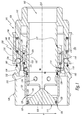
- the male element 100 represented in the state uncoupled to the figure 1 has a generally tubular structure centered on an axis XX.
- a radial direction or all that is characterized radially refers to a direction perpendicular to the axis XX.
- the body 101 of this male element 100 comprises a piston 102 and a structure 104 which respectively constitute the inner and outer parts of the body 101 of the male element 100.
- the piston 102 comprises a generally conical portion 106 and a generally cylindrical portion 108, both are substantially centered on the axis XX.
- the conical portion 106 of the piston 102 is situated at the front of the male element 100, that is to say turned, during coupling, to a complementary element of the connection to which the male element 100 belongs.
- conical portion 106 and the cylindrical portion 108 of the piston 102 form a single block.
- the cylindrical portion 108 defines an internal fluid flow channel 162 in the connecting member 100 and has in its forward end portion, that is to say in contact with the conical portion 106, openings 207 in which the fluid can flow when the fitting is coupled.
- the conical portion 106 has an outer radial surface 107 while the cylindrical portion 108 of the piston 102 has an outer radial surface 109, having a peripheral hollow housing 114.
- the body 101 of the male member 100 is formed of a single block, the piston 102 and the external structure 104 being connected by a rear end portion 110 of the body 101, the flow channel 162 being connected to a pipe not shown at the rear end portion 110.
- the outer structure 104 thus extends from this rear end portion 110 to the front end portion of the body 101, the same axial level of which is substantially located the conical portion 106 piston 102.
- a generally tubular sealing ring 120 is disposed radially between the piston 102 and the outer portion 104.
- a first seal 123, housed at the outer radial surface 107 is disposed radially between the sealing ring 120 and the tapered portion 106 of the piston 102 and a second seal 124, housed at the outer radial surface 109, at the front of the hollow peripheral housing 114, is disposed radially between the cylindrical portion 108 of the piston 102 and the sealing ring 120, which ensures a sealed overlap of the piston 102 at the openings 207 by the sealing ring 120 in uncoupled configuration and thus the closure of the flow channel 162 and the pipe connected to the element connection 100.
- a shoulder 125 is defined, resulting in a narrowing of the diameter of the seal ring forward. Note a first planar face 126 of the sealing ring 120, as the front axial end. In the same way, a second planar face 113 is noted as the forward axial end of the piston 102.
- the shoulder 125 also has an inner surface 128 and an outer surface 129.
- the sealing ring 120 has, in its portion substantially at the same axial level as the seal 123 an internal diameter ⁇ 1 and, in its portion substantially at the same axial level as the seal 124, an inside diameter ⁇ 2.
- ⁇ 1 and ⁇ 2 are the sealing diameters of the sealing ring 120 with the piston 102 in uncoupled configuration.
- ⁇ 1 is strictly less than ⁇ 2 for example of the order of 0.15 mm: this has the advantage, in the presence of a fluid under pressure inside the sealing ring, to press the sealing ring 120 forwardly in abutment against a shoulder 117 of the piston 102. Indeed, the pressure of the fluid on the inner surface of the sealing ring 120, in particular at the surface 128 of the shoulder 125 tends to maintain the closing the male element 100.
- the cylindrical portion 108 of the piston 102 also comprises radial through holes 116 distributed around the axis XX and arranged axially at the front with respect to the seal 124 and at the rear relative to the openings 207 on a portion of the piston 102 which the outside diameter is smaller than the diameter ⁇ 2.
- the pair of plane faces 126 and 113 are planar faces flush with each other. This cleverly allows to limit fluid residues.
- the sealing ring 120 is movable along the axis XX relative to the piston 102 during coupling and uncoupling and carries a coupling member 130. This coupling member 130 is movable radially relative to the ring. sealing device and comprises or consists of hitch balls 131.
- 12 coupling balls are housed and radially movable in respective cylindrical housings 115 formed in the sealing ring 120 around of the axis XX and, in the uncoupled configuration, are partially arranged in the hollow housing 114 of the cylindrical portion 108 of the piston 102.
- a memory ring 142 is disposed radially between the sealing ring 120 and the outer portion 104 of the male body 101.
- a spring 144 is interposed between the sealing ring 120 and the memory ring 142 along the axis XX and pushes the ring memory 142 towards the front of the connecting element 100 and abutting against a shoulder 103 of the sealing ring 120.
- the memory ring 120 In uncoupled configuration, the memory ring 120, then abutting against the shoulder 103, radially covers the balls coupling 131 housed both in the cylindrical housings 115 and in the hollow housing 114, where they are locked, in axial cooperation with the piston 102, for coupling the body 101 and the sealing ring 120, in other words to axially, in close clearance, the body 101 and the sealing ring 120.
- the hitching of the body 101 with the sealing ring 120 ensures the sealed covering of the piston 102 by the sealing ring 120.
- the male element 100 also comprises a locking device 150.
- This locking device 150 comprises both a locking ring 152, arranged externally to the external structure 104 of the body 101 of the connecting element 100, locking balls 154 , which are housed radially movable in cylindrical housings 119 of the outer structure 104 of the body 101, and a locking spring 156 which is interposed axially between the outer portion 104 of the body 101 and the locking ring 152 to axially push the locking ring 152 towards the front of the connecting element 100, in the radial overlap position of the locking balls 154.
- the locking balls 154 are arranged radially between the memory ring 142 and the locking ring 152
- the memory ring 142 cooperates with the locking balls 154 protruding radially outwardly of the ext structure. As shown in Fig. 104, this causes the locking ring 152 to move backwards against the locking spring 156, thereby locking the locking device 150 in the unlocked position.
- the internal radial surface 141 of the memory ring 142 which has a diameter ⁇ 3, covers the coupling balls 131 while the outer radial surface 143 of the memory ring 142 covers the locking balls 154.
- a protection ring 105 is defined as a front end portion of the outer structure 104 of the male element 100. This ring protection 105 thus advantageously makes it possible to protect the outer surface of the sealing ring 120 in the event of impact and limits accessibility to the memory ring 142.
- a visual indicator 160 is also positioned externally on the external structure 104 of the body 101 of the male element 100 and is discovered by the locking ring 152 in uncoupled configuration.
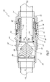
- a complementary coupling element 200 which in the example under consideration is a female element, in the uncoupled configuration.
- This female element 200 has a generally tubular shape about an axis YY and comprises an outer portion 202 which constitutes the body of the female element and a valve 204.
- the outer portion 202 is connected to a pipe not shown.
- the valve 204 closes an opening O1.
- a spring 206 bears on the valve 204 and on the body 202 of the female element, parallel to the axis YY and pushes the valve 204 forward of the body 202 in the closed position against the body 202.
- the body 202 of the female element 200 has on its outer surface 208 a peripheral hollow housing 210 and, on its inner surface 212, a shoulder 214 having an inner surface 215 and widening towards the front, as well as a peripheral hollow housing 216 disposed axially at the front relative to the housing 210 and the shoulder 214.
- the front end of the body 202 of the female element that is to say turned towards the element male 100 during coupling has a minimum inside diameter ⁇ 6, disposed at the front of the hollow housing 216.
- a seal 217 is housed in the body 202 at the opening O1, and arranged radially between the valve 204 and the body of the female element 202.
- the figure 3 represents an intermediate position of the coupling between the male element 100 and the female element 200, the axes XX and YY being then merged forming a coupling axis.
- the body 202 of the female element 200 is brought around the sealing ring 120 and comes into axial contact with the memory ring 142, thus pushing it towards the rear of the body 101 against the spring 144.
- the mating force implemented directly combat axial forces related to the elastic force of the spring 206 of the valve 204, the friction force of the seal 217 of the valve 204 and the elastic force of the spring memory 144.
- the memory ring 142 in cooperation with the body 202, then shifts axially relative to the balls coupling 131 and stops blocking them in the hollow housing 114.
- the body 202 of the female element 200 then comes into contact with the sealing ring 120 by abutment between the inner surface 215 of the shoulder 214 of the body 202 of the female element 200 and the outer surface 129 of the shoulder 125 of the sealing ring 120.
- the seal is then operative between the sealing ring 120 and the female body 202 via the seal 217, the same as between the sealing ring 120 and the piston 102 via the seal 124.
- the piston 102 pushing the valve 204 towards the rear of the body 202 against the spring valve 206, the valve 204 away from the male element.
- the hollow housing 216 reaches radially opposite the coupling balls 131 and the progression of the female element 200 in the coupling direction sets in axial translation, towards the rear of the connecting element 100, the sealing ring 120.
- the coupling balls 131 being released from the cover of the memory ring 142, and facing the housings 216, progress with the sealing ring 120 towards the rear of the connecting element 100 and are radially driven out of the inner housing. 114 of the outer surface of the piston 102 to the hollow housing 216 of the female body 202, thereby passing the connector into the configuration of the figure 4 , where the coupling balls 131 are partially engaged in the hollow housing 216 and the seal is broken between the sealing ring 120 and the piston 102, more particularly at the seal 123.
- the sealing ring 120 is in an open position in which the fluid can flow in the connection between the two elements of the fitting.
- the spring 144 is interposed between the sealing ring 120 and the memory ring 142, so that as soon as the sealing ring 120 is pushed back by the body 202 of the female element 200, the operator no longer has to fight against the elastic force of the spring 144 to continue the coupling. The operator must however combat the friction forces of the seals 123, 124 and the elastic force of the spring 206, then, as soon as the fluid flows in the connection, only the friction of the seal 124 and the effort resilient spring 206.
- the coupling member 130 for coupling the piston 102 and the sealing ring 120 in uncoupled configuration successively fulfills another function which is the axial connection of the sealing ring 120 with the body of the female element 202.
- each coupling ball 131 housed in a housing 115, which is respectively in a first position engaged in the housing 114 of the piston 102 and goes into a second position engaged in the housing 216 of the body of the female element 202.
- the external surface 109 of the piston 102 at the rear of the housing 114, radially covers the coupling balls 131 in the cylindrical housings 115, engaged in the housing 216.
- the coupling balls 131 are then locked in axial cooperation with the body 202 axially solidarisant the sealing ring 120 and the body 202.
- the housing 210 located on the outer surface 212 of the female element 200 is positioned in radial alignment with the locking balls 154.
- the locking balls 154 are then pushed by the locking ring 152, in the locked position in the housing 210 provided for this purpose.
- the locking ring 152 driven by the locking spring 156, then comes into locked position externally cover the locking balls 154: the body 101 is axially locked with the body 202 and the coupling is coupled.
- the coupling balls 131 are always locked by the outer radial surface 109 in their second position of axial connection of the sealing ring 120 with the body 202.
- the body 101 of the connecting element 100 therefore allows the coupling balls to be locked in their second position while the sealing ring 120 moves between the closed position and the open position.
- the visual indicator 160 is then no longer visible because covered by the locking ring 152 as shown figure 5 in coupled configuration. This visual indicator 160 therefore makes it possible to testify whether the system is locked or not.
- the memory ring 142 thus serves both during the coupling, to successively discover in this order the coupling balls 131 and the locking balls 154.
- the memory ring 142 can be replaced by two separate parts respectively assuming the locking function in connection with the coupling member 130 and the memory function in connection with the locking device. locking 150.
- the coupling of the sealing ring 120 with the female body 202 by the coupling balls 131 makes it possible to open the circuit safely before locking the coupling. Indeed, in the case where the coupling would be interrupted before locking the connector, by removing the element 200 out of the male element 100, the circuit would be closed again without risk of leakage since the withdrawal of the female body 202 would jointly cause the withdrawal of the sealing ring 120. This until the sealing ring is disengaged from the female body 202 and is held axially with the piston 102, thus ensuring a sealed covering thereof.
- the memory ring 142 acting on the locking balls 154, ensures an automatic coupling, that is to say under the sole action of fitting the body 202 in the connecting member 100, without recoil of the locking ring 152 and with axial mating forces minimized.
- the sealing ring 120 comes, in the continuation of its movement, covering the cylindrical portion 108 of the piston 102.
- the sealing ring 120 is then able to cause in its movement of the fluid, which can remain trapped between the inner surface the sealing ring, at the inner surface 128, and the outer radial surface of the cylindrical portion 108 of the piston 102, overlapping the front of the seal 124.
- the radial through holes 116 then allow to evacuate these possible fluid residues towards the inside of the piston 102.
- the sealing ring 120 guarantees the tightness of the connection of the two connecting elements 100 and 200 by cooperating with the seal 217 and the seal 124.
- the sealing diameter ⁇ 5 of the sealing ring 120 with the body 202 at the joint 217, corresponding to the outer diameter of the sealing ring 120 in contact with the seal 217, is strictly less than the sealing diameter ⁇ 2 of the sealing ring 120 with the body 101, at the joint 124, corresponding to the inside diameter of the sealing ring in contact with the seal 124, the differential being of the order of 0.15 mm.
- the force of the circulating fluid tends to push the sealing ring 120 towards the front of the connecting element 100, in contact with the body 202, so that the coupling balls 131 do not undergo any damage. Efforts related to fluid pressure.
- the operator When uncoupling, the operator is asked to unlock the connector first, pulling back on the locking ring 154, thus revealing the visual locking indicator 160 and leaving a radial clearance clearance to the outside for the locking balls 154.
- the user compresses the locking spring 156 intended to return the locking ring by overlapping the locking balls 154.
- the user By removing the body 202 of the female element 200 from the male element 100, the user pushes back radially outwardly the locking balls 154 which protrude from the housing 210 and drives, by means of the coupling balls 131 held in the housing 216 of the inner surface 212 of the body 202 of the female element 200, the ring 120.
- the memory ring 142 driven integrally of the sealing ring 120 and pushed by the spring 144, is inserted under the locking balls 154, blocking the locking device 150 in the unlocked position. Then, the coupling balls 131 radially reach the hollow housing 114 of the cylindrical portion 108 of the piston 102 with the sealing ring 120 abutting against the shoulder 117 of the piston 102. The coupling balls 131 then cease to solidify. axially the sealing ring 120 and the body 202 of the female member 200 while the sealing ring 120 has sealed the piston 102 and thus interrupted the flow of fluid.
- the memory ring 142 pushed by the spring 144 then intelligently covers the coupling balls 131 in the housing 114 to maintain the sealing ring 120 in the closed position of the flow channel 162.
- the spring 144 is just sized to push the memory in the overlap position of the coupling balls 131 and the locking balls 154.
- this spring 144 is not dimensioned according to the friction induced by the joints 123, 124 and 217 under pressure, the elastic force of the spring 144 is substantially less than the friction forces of the joints 123, 124 and 217.
- the internal diameter ⁇ 6 of the body 202 of the female element 200 is provided strictly less than the internal diameter ⁇ 3 of the memory ring 142.
- the memory ring 140 has a radial clearance with the cylindrical housings 115 of the balls coupling 131 greater than the radial clearance, the front end of the body 202 of the female element 200 has with the cylindrical housings 115. This advantageously allows to facilitate the movement of the memory ring 142, under the sole effort resilient spring 144, limiting friction when the inner surface of minimum diameter ⁇ 6 shifts relative to the coupling balls 131 during uncoupling and the internal surface diameter ⁇ 3 comes in radial overlap coupling balls 131.
- the memory ring 142 has already covered the locking balls 154 when it must cover the coupling balls 131 in the hollow housing 114. This decoupling makes it possible to minimize the elastic force of the spring 144.
- the coupling of the sealing ring 120 with the female body 202 by the coupling balls 131 throughout the displacement of the sealing ring 120 relative to the body 101 as well as the coupling of the sealing ring 120 with the body 101 uncoupled configuration allow to suppress the elastic return of the sealing ring 120 in the closed position relative to the body 101 and thus to reduce the connection forces, compared to the connection of the state of the 'art.
Landscapes
- Engineering & Computer Science (AREA)
- General Engineering & Computer Science (AREA)
- Mechanical Engineering (AREA)
- Quick-Acting Or Multi-Walled Pipe Joints (AREA)
Claims (12)
- Fluidkupplung, ein Kupplungselement (100) und ein komplementäres Kupplungselement (200) umfassend, die geeignet sind, gemäß einer Verbindungsachse (X-X, Y-Y) miteinander gekuppelt zu werden, wobei das Kupplungselement (100) umfasst:- einen Körper (101), der in dem Kupplungselement (100) einen Strömungskanal (162) für das Fluid begrenzt,- eine Verriegelungsvorrichtung (150), die geeignet ist, axial den Körper (101) des Kupplungselements (100) mit einem Körper (202) des komplementären Elements zu verriegeln, wenn die Kupplung in der verkuppelten Stellung ist und- einen Dichtungsring (120), der während des Verkuppelns und Entkuppelns der Kupplung in Bezug auf den Körper (101) des Kupplungselements verschiebbar ist, zwischen:- einer Stellung des Verschlusses des Strömungskanals (162) des Körpers (101) des Kupplungselements (100), wenn die Kupplung in der entkuppelten Stellung ist und- eine Offenstellung, in der das Fluid in der Kupplung strömen kann,wobei dieser Dichtungsring (120) einen Raum (115) zur Aufnahme eines Verspannelements (131) in dem das Verspannelement (131) beweglich ist zwischen:- einer erste Stellung, in der in der Verschlussstellung das Verspannelement (131) den Körper (101) des Kupplungselements (100) axial mit dem Dichtungsring (120) verbindet, und- einer zweiten Stellung, in der in der Offenstellung das Verspannelement (131) den Körper (202) des komplementären Kupplungselements (200) axial mit dem Dichtungsring (120) verbindet,- ein Blockierelement (142), das angepasst ist, das Verspannelement (131) in seiner ersten Stellung zu blockieren und mit dem Körper (202) des komplementären Kupplungselements (200) während des Verbindens der Kupplung zusammenzuarbeiten, um den Übergang des Verspannelements (131) von der ersten Stellung in die zweite Stellung zuzulassen,
wobei diese Kupplung dadurch gekennzeichnet ist, dass während des Verkuppelns und des Entkuppeln der Kupplung der Körper (101) des Kupplungselements geeignet ist, das Verspannelement (131) in der zweiten Stellung zu blockieren, bei der der Dichtungsring (120) sich verschiebt zwischen der Verschlussstellung und einer Offenstellung, in der die Verriegelungsvorrichtung (150) axial den Körper (202) des komplementären Kupplungselements (200) in Bezug auf den Körper (101) des Kupplungselements (100) verriegelt. - Kupplung nach Anspruch 1, dadurch gekennzeichnet, dass der Körper (101) des Kupplungselements (100) einen Innenkolben (102) und einen äußeren Bereich (104) des Körpers aufweist, radial zwischen denen der Dichtungsring (120) und das Blockierelement (142) angeordnet sind, und dass der Körper (202) des komplementären Kupplungselements (200) um den Dichtungsring (120) während des Verkuppelns und Entkuppelns der Kupplung in Stellung gebracht wird.
- Kupplung nach Anspruch 2, dadurch gekennzeichnet, dass der Körper (202) des komplementären Kupplungselements (200) einen vertieften inneren Aufnahmeraum (216), der das Verspannelement (131) aufnimmt, wenn das Verspannelement (131) in seiner zweiten Stellung ist, und einen vertieften äußeren Aufnahmeraum (210) aufweist, der ein Verriegelungselement (154) der Verriegelungsvorrichtung (150) aufnimmt, wenn die Kupplung verkuppelt ist.
- Kupplung nach Anspruch 3, dadurch gekennzeichnet, dass in der verkuppelten Stellung der Kupplung der Durchmesser (φ5) der Abdichtung des Dichtungsrings (120) mit dem Körper (202) des komplementären Kupplungselements (200) streng kleiner als der Durchmesser der Abdichtung (φ2) des Dichtungsrings (120) mit dem Körper (101) des Kupplungselements (100) ist.
- Kupplung nach einem beliebigen der Ansprüche 2 bis 4, dadurch gekennzeichnet, dass in der entkuppelten Stellung der Kupplung der Durchmesser (φ1) der Abdichtung des Kolbens mit dem Dichtungsring (120) an seinem an einem vorderen Ende des Kupplungselements (100) liegenden Bereichs, der dazu dient, zum komplementären Kupplungselement (200) bei dem Verkuppeln gerichtet zu sein, streng kleiner ist als der Durchmesser der Abdichtung (φ2) des Kolbens (102) mit dem Dichtungsring (120) in seinem Bereich, der die Dichtigkeit zu dem Kolben (102) nach hinten sicherstellt.
- Kupplung nach einem beliebigen der vorhergehenden Ansprüche, dadurch gekennzeichnet, dass das Kupplungselement (100) außerdem eine Feder (144) umfasst, die axial zwischen dem Dichtungsring (120) und dem Blockierelement (142) angeordnet ist und die das Blockierelement (142) zu seiner Blockierstellung des Verspannelements (131) in seiner ersten Stellung vorspannt, wenn die Kupplung entkuppelt ist.
- Kupplung nach einem der vorhergehenden Ansprüche, dadurch gekennzeichnet, dass das Verspannelement (131) mindestens eine Verspannkugel (131) umfasst, die radial in dem Dichtungsring (120) beweglich ist, und dass das Blockierelement (140) ein Blockierring (142) ist, der geeignet ist, radial die Verspannkugel in ihrer ersten Stellung zu überdecken, in der die Verspannkugel (131) axial mit einer Aufnahme (114) des Körpers (101) des Kupplungselements (100) zusammenarbeitet.
- Kupplung nach Anspruch 7, dadurch gekennzeichnet, dass das vordere Ende des Körpers (202) des komplementären Kupplungselements (200) einen inneren Durchmesser (φ6) aufweist, der streng kleiner ist als der innere Durchmesser (φ3) einer Innenfläche des Blockierrings (142), der die Verspannkugel (131) überdeckt, wenn die Kupplung in ihrer entkuppelten Stellung ist.
- Kupplung nach einem beliebigen der vorhergehenden Ansprüche, dadurch gekennzeichnet, dass das Kupplungselement (100) ein Speicherelement (142) umfasst, das geeignet ist, die Verriegelungsvorrichtung (150) in der entriegelten Stellung zu blockieren, wenn die Kupplung in ihrer entkuppelten Stellung ist, und mit dem Körper (202) des komplementären Kupplungselements (200) während des Verkuppelns der Kupplung zusammenzuarbeiten, um den Übergang der Verriegelungsvorrichtung (150) in die verriegelte Stellung zu gestatten.
- Kupplung nach Anspruch 9, dadurch gekennzeichnet, dass das Speicherelement ein Speicherring (142) ist, der von einer Feder (144) in eine Stellung der radialen Überdeckung eines zu der Verriegelungsvorrichtung (150) gehörenden Verriegelungselements (154) vorgespannt ist, in der der Speicherring (142) die Verriegelungsvorrichtung (150) in der entriegelten Stellung blockiert, wenn die Kupplung entkuppelt ist.
- Kupplung nach einem der Ansprüche 9 oder 10, dadurch gekennzeichnet, dass das Blockierelement und das Speicherelement ein selber Ring (142) sind und dass in der entkuppelten Stellung der Kupplung die Innenfläche des Rings (142) radial das Verspannelement (131) in der ersten Stellung bedeckt und die Außenfläche des Rings (142) radial das Verriegelungselement (154) in seiner entriegelten Stellung überdeckt.
- Kupplung nach einem der Ansprüche 10 oder 11, dadurch gekennzeichnet, dass der Speicherring (142) geeignet ist, während des Verkuppelns der Kupplung jeweils und aufeinanderfolgend das Verspannelement (131) und das Verriegelungselement (154) freizulegen.
Applications Claiming Priority (1)
| Application Number | Priority Date | Filing Date | Title |
|---|---|---|---|
| FR1261434A FR2998638B1 (fr) | 2012-11-29 | 2012-11-29 | Raccord |
Publications (2)
| Publication Number | Publication Date |
|---|---|
| EP2738437A1 EP2738437A1 (de) | 2014-06-04 |
| EP2738437B1 true EP2738437B1 (de) | 2015-09-09 |
Family
ID=47754707
Family Applications (1)
| Application Number | Title | Priority Date | Filing Date |
|---|---|---|---|
| EP13194888.7A Active EP2738437B1 (de) | 2012-11-29 | 2013-11-28 | Rohrleitungskupplung |
Country Status (5)
| Country | Link |
|---|---|
| US (1) | US9080712B2 (de) |
| EP (1) | EP2738437B1 (de) |
| KR (1) | KR102143983B1 (de) |
| CN (1) | CN103851285B (de) |
| FR (1) | FR2998638B1 (de) |
Families Citing this family (14)
| Publication number | Priority date | Publication date | Assignee | Title |
|---|---|---|---|---|
| US10093532B2 (en) | 2014-08-14 | 2018-10-09 | Flomax International, Inc. | Nozzle and keyed flush face receiver |
| DE102015222639A1 (de) * | 2015-11-17 | 2017-05-18 | U.M. Gewerbeimmobilien Gmbh & Co. Kg | Kupplungsmuffe für eine Hydraulikkupplung |
| FR3048822B1 (fr) * | 2016-03-11 | 2018-04-06 | Staubli Faverges | Raccord electrique |
| AU2017266442C1 (en) * | 2016-05-19 | 2023-09-07 | Walnab Pty Ltd | Fluid coupling assembly |
| FR3056672B1 (fr) * | 2016-09-28 | 2019-06-21 | Staubli Faverges | Raccord et circuit hydraulique de freinage pour cycle incorporant un tel raccord |
| US10781957B2 (en) * | 2017-01-24 | 2020-09-22 | Staubli Faverges | Fluid coupling element and fluid-coupling comprising such an element |
| US10941892B2 (en) * | 2017-02-17 | 2021-03-09 | Hewlett Packard Enterprise Development Lp | Valved connector |
| EP3719381B1 (de) * | 2018-02-09 | 2023-06-28 | Tatsuno Corporation | Füllvorrichtung |
| FR3079592B1 (fr) * | 2018-04-03 | 2020-04-24 | Staubli Faverges | Raccord fluidique |
| EP4166833B1 (de) * | 2018-08-10 | 2024-10-02 | Parker-Hannifin Corporation | Verbindbare/lösbare schnellkupplung |
| KR102157086B1 (ko) * | 2018-12-31 | 2020-09-17 | 정운택 | 체크 밸브 |
| FR3097565B1 (fr) * | 2019-06-19 | 2022-08-12 | Staubli Sa Ets | Machine textile, métier à tisser comportant une telle machine textile et procédés associés |
| US10935176B1 (en) | 2019-09-03 | 2021-03-02 | Loon Llc | Multi port fluid connector |
| DE102021114973A1 (de) * | 2021-06-10 | 2022-12-15 | Norma Germany Gmbh | Ventil für eine Fluidleitung eines Fahrzeugs |
Family Cites Families (9)
| Publication number | Priority date | Publication date | Assignee | Title |
|---|---|---|---|---|
| DE1078826B (de) * | 1953-02-18 | 1960-03-31 | Otto Bilz | Ventilkupplung fuer Schlauchleitungen |
| US3076671A (en) * | 1959-02-05 | 1963-02-05 | Lucas Industries Ltd | Quick connect coupling |
| US4114853A (en) * | 1976-10-08 | 1978-09-19 | Swagelok Company | Quick connect coupling |
| DE2724630C3 (de) * | 1977-06-01 | 1980-01-24 | Robert Volker Ing.(Grad.) 7502 Malsch Pfeiffer | Rohrleitungskupplung, insbesondere für Hoch- und Höchstdruckleitungen |
| US5709243A (en) * | 1995-11-20 | 1998-01-20 | Aeroquip Corporation | Low spill female coupling |
| ITMI20011105A1 (it) * | 2001-05-25 | 2002-11-25 | Faster Srl | Innesto rapido a faccia piana, con mezzi per evitare una fuoriuscita di fluido idraulico durante la fase di accoppiamento o di disaccoppiame |
| JP3878903B2 (ja) * | 2002-10-25 | 2007-02-07 | 日東工器株式会社 | 管継手 |
| US20050255189A1 (en) * | 2004-05-17 | 2005-11-17 | Manda Jan M | Method and apparatus for coupling melt conduits in a molding system and/or a runner system |
| US7673911B2 (en) * | 2008-03-06 | 2010-03-09 | Liu Hsiu-Hsiung | Safety type quick connector |
-
2012
- 2012-11-29 FR FR1261434A patent/FR2998638B1/fr not_active Expired - Fee Related
-
2013
- 2013-11-20 US US14/085,115 patent/US9080712B2/en active Active
- 2013-11-27 KR KR1020130145707A patent/KR102143983B1/ko active IP Right Grant
- 2013-11-28 EP EP13194888.7A patent/EP2738437B1/de active Active
- 2013-11-29 CN CN201310628341.9A patent/CN103851285B/zh active Active
Also Published As
| Publication number | Publication date |
|---|---|
| FR2998638B1 (fr) | 2016-04-15 |
| US9080712B2 (en) | 2015-07-14 |
| EP2738437A1 (de) | 2014-06-04 |
| KR20140070427A (ko) | 2014-06-10 |
| KR102143983B1 (ko) | 2020-08-12 |
| US20140174577A1 (en) | 2014-06-26 |
| FR2998638A1 (fr) | 2014-05-30 |
| CN103851285B (zh) | 2017-04-12 |
| CN103851285A (zh) | 2014-06-11 |
Similar Documents
| Publication | Publication Date | Title |
|---|---|---|
| EP2738437B1 (de) | Rohrleitungskupplung | |
| EP1853842B1 (de) | Schnellkupplung zur verbindung zweier druckgasleitungen | |
| EP0799396B1 (de) | Schnellverbindung mit entkupplung in zwei stufen | |
| EP3184871B1 (de) | Steckanschlusselement oder buchse eines schnellanschlusses, und ein solches element umfassender schnellanschluss | |
| EP3255332B1 (de) | Schnellanschlusselement mit auslassorgan, und schnellanschluss mit einem solchen schnellanschlusselement | |
| EP2623916B1 (de) | Kühlsystem mit Kühlkreislaufleitung mit Wärmeübertragungsflüssigkeit | |
| EP1980782B1 (de) | Anschlussbuchse und eine Schnellverbindung mit einer solchen Buchse | |
| FR2927143A1 (fr) | Element femelle de raccord et raccord rapide incorporant un tel element | |
| FR3056672B1 (fr) | Raccord et circuit hydraulique de freinage pour cycle incorporant un tel raccord | |
| EP3184870B1 (de) | Buchse eines schnellanschlusses, und eine solche buchse umfassender schnellanschluss | |
| EP3581836B1 (de) | Flüssigkeitskupplung | |
| EP3411616B1 (de) | Verbindungsvorrichtung und verfahren | |
| EP2587109B1 (de) | Anschlussvorrichtung | |
| FR3071301B1 (fr) | Coupe-circuit et installation de manutention de fluide sous pression comprenant un tel coupe-circuit | |
| EP1625322B1 (de) | Schnellverschlusskupplung für hydraulikflüssigkeitsleitungen | |
| CA3135534C (fr) | Dispositif de raccordement avec une position intermediaire de deverrouillage | |
| EP0847511B1 (de) | Schnellkupplung für druckleitungen | |
| EP4040028B1 (de) | Anschlusselement | |
| EP3798490B1 (de) | Fluidanschlusselement | |
| CA3107828A1 (fr) | Raccord fluidique | |
| FR3057049B1 (fr) | Raccord hydraulique auto-obturant. | |
| FR2527741A1 (fr) | Perfectionnements aux raccords rapide pour la jonction amovible des canalisations | |
| EP4306837A1 (de) | Anschlusselement für eine fluidverbindung an ein endgerät | |
| FR2618871A1 (fr) | Raccord rapide avec bague de verrouillage |
Legal Events
| Date | Code | Title | Description |
|---|---|---|---|
| PUAI | Public reference made under article 153(3) epc to a published international application that has entered the european phase |
Free format text: ORIGINAL CODE: 0009012 |
|
| 17P | Request for examination filed |
Effective date: 20131128 |
|
| AK | Designated contracting states |
Kind code of ref document: A1 Designated state(s): AL AT BE BG CH CY CZ DE DK EE ES FI FR GB GR HR HU IE IS IT LI LT LU LV MC MK MT NL NO PL PT RO RS SE SI SK SM TR |
|
| AX | Request for extension of the european patent |
Extension state: BA ME |
|
| R17P | Request for examination filed (corrected) |
Effective date: 20141106 |
|
| RBV | Designated contracting states (corrected) |
Designated state(s): AL AT BE BG CH CY CZ DE DK EE ES FI FR GB GR HR HU IE IS IT LI LT LU LV MC MK MT NL NO PL PT RO RS SE SI SK SM TR |
|
| REG | Reference to a national code |
Ref country code: DE Ref legal event code: R079 Ref document number: 602013002934 Country of ref document: DE Free format text: PREVIOUS MAIN CLASS: F16L0037230000 Ipc: F16L0037300000 |
|
| GRAP | Despatch of communication of intention to grant a patent |
Free format text: ORIGINAL CODE: EPIDOSNIGR1 |
|
| RIC1 | Information provided on ipc code assigned before grant |
Ipc: F16L 55/10 20060101ALI20150305BHEP Ipc: F16L 37/35 20060101ALI20150305BHEP Ipc: F16L 37/23 20060101AFI20150305BHEP Ipc: F16L 37/34 20060101ALI20150305BHEP |
|
| RIC1 | Information provided on ipc code assigned before grant |
Ipc: F16L 37/34 20060101ALI20150310BHEP Ipc: F16L 37/30 20060101AFI20150310BHEP Ipc: F16L 37/35 20060101ALI20150310BHEP Ipc: F16L 37/23 20060101ALI20150310BHEP Ipc: F16L 55/10 20060101ALI20150310BHEP |
|
| INTG | Intention to grant announced |
Effective date: 20150401 |
|
| GRAS | Grant fee paid |
Free format text: ORIGINAL CODE: EPIDOSNIGR3 |
|
| GRAA | (expected) grant |
Free format text: ORIGINAL CODE: 0009210 |
|
| AK | Designated contracting states |
Kind code of ref document: B1 Designated state(s): AL AT BE BG CH CY CZ DE DK EE ES FI FR GB GR HR HU IE IS IT LI LT LU LV MC MK MT NL NO PL PT RO RS SE SI SK SM TR |
|
| REG | Reference to a national code |
Ref country code: GB Ref legal event code: FG4D Free format text: NOT ENGLISH |
|
| REG | Reference to a national code |
Ref country code: AT Ref legal event code: REF Ref document number: 748425 Country of ref document: AT Kind code of ref document: T Effective date: 20150915 Ref country code: CH Ref legal event code: EP |
|
| REG | Reference to a national code |
Ref country code: IE Ref legal event code: FG4D Free format text: LANGUAGE OF EP DOCUMENT: FRENCH |
|
| REG | Reference to a national code |
Ref country code: DE Ref legal event code: R096 Ref document number: 602013002934 Country of ref document: DE |
|
| REG | Reference to a national code |
Ref country code: FR Ref legal event code: PLFP Year of fee payment: 3 |
|
| REG | Reference to a national code |
Ref country code: SE Ref legal event code: TRGR |
|
| REG | Reference to a national code |
Ref country code: NL Ref legal event code: MP Effective date: 20150909 |
|
| PG25 | Lapsed in a contracting state [announced via postgrant information from national office to epo] |
Ref country code: NO Free format text: LAPSE BECAUSE OF FAILURE TO SUBMIT A TRANSLATION OF THE DESCRIPTION OR TO PAY THE FEE WITHIN THE PRESCRIBED TIME-LIMIT Effective date: 20151209 Ref country code: FI Free format text: LAPSE BECAUSE OF FAILURE TO SUBMIT A TRANSLATION OF THE DESCRIPTION OR TO PAY THE FEE WITHIN THE PRESCRIBED TIME-LIMIT Effective date: 20150909 Ref country code: GR Free format text: LAPSE BECAUSE OF FAILURE TO SUBMIT A TRANSLATION OF THE DESCRIPTION OR TO PAY THE FEE WITHIN THE PRESCRIBED TIME-LIMIT Effective date: 20151210 Ref country code: LV Free format text: LAPSE BECAUSE OF FAILURE TO SUBMIT A TRANSLATION OF THE DESCRIPTION OR TO PAY THE FEE WITHIN THE PRESCRIBED TIME-LIMIT Effective date: 20150909 Ref country code: LT Free format text: LAPSE BECAUSE OF FAILURE TO SUBMIT A TRANSLATION OF THE DESCRIPTION OR TO PAY THE FEE WITHIN THE PRESCRIBED TIME-LIMIT Effective date: 20150909 |
|
| REG | Reference to a national code |
Ref country code: LT Ref legal event code: MG4D |
|
| REG | Reference to a national code |
Ref country code: AT Ref legal event code: MK05 Ref document number: 748425 Country of ref document: AT Kind code of ref document: T Effective date: 20150909 |
|
| PG25 | Lapsed in a contracting state [announced via postgrant information from national office to epo] |
Ref country code: HR Free format text: LAPSE BECAUSE OF FAILURE TO SUBMIT A TRANSLATION OF THE DESCRIPTION OR TO PAY THE FEE WITHIN THE PRESCRIBED TIME-LIMIT Effective date: 20150909 Ref country code: RS Free format text: LAPSE BECAUSE OF FAILURE TO SUBMIT A TRANSLATION OF THE DESCRIPTION OR TO PAY THE FEE WITHIN THE PRESCRIBED TIME-LIMIT Effective date: 20150909 Ref country code: ES Free format text: LAPSE BECAUSE OF FAILURE TO SUBMIT A TRANSLATION OF THE DESCRIPTION OR TO PAY THE FEE WITHIN THE PRESCRIBED TIME-LIMIT Effective date: 20150909 |
|
| PG25 | Lapsed in a contracting state [announced via postgrant information from national office to epo] |
Ref country code: NL Free format text: LAPSE BECAUSE OF FAILURE TO SUBMIT A TRANSLATION OF THE DESCRIPTION OR TO PAY THE FEE WITHIN THE PRESCRIBED TIME-LIMIT Effective date: 20150909 |
|
| PG25 | Lapsed in a contracting state [announced via postgrant information from national office to epo] |
Ref country code: EE Free format text: LAPSE BECAUSE OF FAILURE TO SUBMIT A TRANSLATION OF THE DESCRIPTION OR TO PAY THE FEE WITHIN THE PRESCRIBED TIME-LIMIT Effective date: 20150909 Ref country code: SK Free format text: LAPSE BECAUSE OF FAILURE TO SUBMIT A TRANSLATION OF THE DESCRIPTION OR TO PAY THE FEE WITHIN THE PRESCRIBED TIME-LIMIT Effective date: 20150909 Ref country code: CZ Free format text: LAPSE BECAUSE OF FAILURE TO SUBMIT A TRANSLATION OF THE DESCRIPTION OR TO PAY THE FEE WITHIN THE PRESCRIBED TIME-LIMIT Effective date: 20150909 Ref country code: IS Free format text: LAPSE BECAUSE OF FAILURE TO SUBMIT A TRANSLATION OF THE DESCRIPTION OR TO PAY THE FEE WITHIN THE PRESCRIBED TIME-LIMIT Effective date: 20160109 |
|
| PG25 | Lapsed in a contracting state [announced via postgrant information from national office to epo] |
Ref country code: RO Free format text: LAPSE BECAUSE OF FAILURE TO SUBMIT A TRANSLATION OF THE DESCRIPTION OR TO PAY THE FEE WITHIN THE PRESCRIBED TIME-LIMIT Effective date: 20150909 Ref country code: PT Free format text: LAPSE BECAUSE OF FAILURE TO SUBMIT A TRANSLATION OF THE DESCRIPTION OR TO PAY THE FEE WITHIN THE PRESCRIBED TIME-LIMIT Effective date: 20160111 Ref country code: PL Free format text: LAPSE BECAUSE OF FAILURE TO SUBMIT A TRANSLATION OF THE DESCRIPTION OR TO PAY THE FEE WITHIN THE PRESCRIBED TIME-LIMIT Effective date: 20150909 Ref country code: AT Free format text: LAPSE BECAUSE OF FAILURE TO SUBMIT A TRANSLATION OF THE DESCRIPTION OR TO PAY THE FEE WITHIN THE PRESCRIBED TIME-LIMIT Effective date: 20150909 |
|
| REG | Reference to a national code |
Ref country code: DE Ref legal event code: R097 Ref document number: 602013002934 Country of ref document: DE |
|
| PG25 | Lapsed in a contracting state [announced via postgrant information from national office to epo] |
Ref country code: LU Free format text: LAPSE BECAUSE OF FAILURE TO SUBMIT A TRANSLATION OF THE DESCRIPTION OR TO PAY THE FEE WITHIN THE PRESCRIBED TIME-LIMIT Effective date: 20151128 Ref country code: MC Free format text: LAPSE BECAUSE OF FAILURE TO SUBMIT A TRANSLATION OF THE DESCRIPTION OR TO PAY THE FEE WITHIN THE PRESCRIBED TIME-LIMIT Effective date: 20150909 |
|
| PLBE | No opposition filed within time limit |
Free format text: ORIGINAL CODE: 0009261 |
|
| STAA | Information on the status of an ep patent application or granted ep patent |
Free format text: STATUS: NO OPPOSITION FILED WITHIN TIME LIMIT |
|
| 26N | No opposition filed |
Effective date: 20160610 |
|
| REG | Reference to a national code |
Ref country code: IE Ref legal event code: MM4A |
|
| PG25 | Lapsed in a contracting state [announced via postgrant information from national office to epo] |
Ref country code: DK Free format text: LAPSE BECAUSE OF FAILURE TO SUBMIT A TRANSLATION OF THE DESCRIPTION OR TO PAY THE FEE WITHIN THE PRESCRIBED TIME-LIMIT Effective date: 20150909 Ref country code: SI Free format text: LAPSE BECAUSE OF FAILURE TO SUBMIT A TRANSLATION OF THE DESCRIPTION OR TO PAY THE FEE WITHIN THE PRESCRIBED TIME-LIMIT Effective date: 20150909 |
|
| PG25 | Lapsed in a contracting state [announced via postgrant information from national office to epo] |
Ref country code: IE Free format text: LAPSE BECAUSE OF NON-PAYMENT OF DUE FEES Effective date: 20151128 |
|
| REG | Reference to a national code |
Ref country code: FR Ref legal event code: PLFP Year of fee payment: 4 |
|
| PG25 | Lapsed in a contracting state [announced via postgrant information from national office to epo] |
Ref country code: BG Free format text: LAPSE BECAUSE OF FAILURE TO SUBMIT A TRANSLATION OF THE DESCRIPTION OR TO PAY THE FEE WITHIN THE PRESCRIBED TIME-LIMIT Effective date: 20150909 Ref country code: HU Free format text: LAPSE BECAUSE OF FAILURE TO SUBMIT A TRANSLATION OF THE DESCRIPTION OR TO PAY THE FEE WITHIN THE PRESCRIBED TIME-LIMIT; INVALID AB INITIO Effective date: 20131128 |
|
| PG25 | Lapsed in a contracting state [announced via postgrant information from national office to epo] |
Ref country code: CY Free format text: LAPSE BECAUSE OF FAILURE TO SUBMIT A TRANSLATION OF THE DESCRIPTION OR TO PAY THE FEE WITHIN THE PRESCRIBED TIME-LIMIT Effective date: 20150909 |
|
| REG | Reference to a national code |
Ref country code: CH Ref legal event code: PL |
|
| PG25 | Lapsed in a contracting state [announced via postgrant information from national office to epo] |
Ref country code: CH Free format text: LAPSE BECAUSE OF NON-PAYMENT OF DUE FEES Effective date: 20161130 Ref country code: BE Free format text: LAPSE BECAUSE OF NON-PAYMENT OF DUE FEES Effective date: 20151130 Ref country code: LI Free format text: LAPSE BECAUSE OF NON-PAYMENT OF DUE FEES Effective date: 20161130 |
|
| PG25 | Lapsed in a contracting state [announced via postgrant information from national office to epo] |
Ref country code: MT Free format text: LAPSE BECAUSE OF FAILURE TO SUBMIT A TRANSLATION OF THE DESCRIPTION OR TO PAY THE FEE WITHIN THE PRESCRIBED TIME-LIMIT Effective date: 20150909 |
|
| REG | Reference to a national code |
Ref country code: FR Ref legal event code: PLFP Year of fee payment: 5 |
|
| PG25 | Lapsed in a contracting state [announced via postgrant information from national office to epo] |
Ref country code: SM Free format text: LAPSE BECAUSE OF FAILURE TO SUBMIT A TRANSLATION OF THE DESCRIPTION OR TO PAY THE FEE WITHIN THE PRESCRIBED TIME-LIMIT Effective date: 20150909 |
|
| PG25 | Lapsed in a contracting state [announced via postgrant information from national office to epo] |
Ref country code: MK Free format text: LAPSE BECAUSE OF FAILURE TO SUBMIT A TRANSLATION OF THE DESCRIPTION OR TO PAY THE FEE WITHIN THE PRESCRIBED TIME-LIMIT Effective date: 20150909 |
|
| GBPC | Gb: european patent ceased through non-payment of renewal fee |
Effective date: 20171128 |
|
| PG25 | Lapsed in a contracting state [announced via postgrant information from national office to epo] |
Ref country code: AL Free format text: LAPSE BECAUSE OF FAILURE TO SUBMIT A TRANSLATION OF THE DESCRIPTION OR TO PAY THE FEE WITHIN THE PRESCRIBED TIME-LIMIT Effective date: 20150909 |
|
| PG25 | Lapsed in a contracting state [announced via postgrant information from national office to epo] |
Ref country code: GB Free format text: LAPSE BECAUSE OF NON-PAYMENT OF DUE FEES Effective date: 20171128 |
|
| P01 | Opt-out of the competence of the unified patent court (upc) registered |
Effective date: 20230509 |
|
| PGFP | Annual fee paid to national office [announced via postgrant information from national office to epo] |
Ref country code: TR Payment date: 20231109 Year of fee payment: 11 Ref country code: SE Payment date: 20231127 Year of fee payment: 11 Ref country code: IT Payment date: 20231122 Year of fee payment: 11 Ref country code: FR Payment date: 20231127 Year of fee payment: 11 Ref country code: DE Payment date: 20231129 Year of fee payment: 11 |