EP2738366A1 - SCR-System und Verfahren zu dessen Spülung - Google Patents
SCR-System und Verfahren zu dessen Spülung Download PDFInfo
- Publication number
- EP2738366A1 EP2738366A1 EP20130194064 EP13194064A EP2738366A1 EP 2738366 A1 EP2738366 A1 EP 2738366A1 EP 20130194064 EP20130194064 EP 20130194064 EP 13194064 A EP13194064 A EP 13194064A EP 2738366 A1 EP2738366 A1 EP 2738366A1
- Authority
- EP
- European Patent Office
- Prior art keywords
- chamber
- additive
- pump
- injection channel
- sliding
- Prior art date
- Legal status (The legal status is an assumption and is not a legal conclusion. Google has not performed a legal analysis and makes no representation as to the accuracy of the status listed.)
- Granted
Links
Images

Classifications
-
- F—MECHANICAL ENGINEERING; LIGHTING; HEATING; WEAPONS; BLASTING
- F01—MACHINES OR ENGINES IN GENERAL; ENGINE PLANTS IN GENERAL; STEAM ENGINES
- F01N—GAS-FLOW SILENCERS OR EXHAUST APPARATUS FOR MACHINES OR ENGINES IN GENERAL; GAS-FLOW SILENCERS OR EXHAUST APPARATUS FOR INTERNAL-COMBUSTION ENGINES
- F01N3/00—Exhaust or silencing apparatus having means for purifying, rendering innocuous, or otherwise treating exhaust
- F01N3/08—Exhaust or silencing apparatus having means for purifying, rendering innocuous, or otherwise treating exhaust for rendering innocuous
- F01N3/10—Exhaust or silencing apparatus having means for purifying, rendering innocuous, or otherwise treating exhaust for rendering innocuous by thermal or catalytic conversion of noxious components of exhaust
-
- F—MECHANICAL ENGINEERING; LIGHTING; HEATING; WEAPONS; BLASTING
- F01—MACHINES OR ENGINES IN GENERAL; ENGINE PLANTS IN GENERAL; STEAM ENGINES
- F01N—GAS-FLOW SILENCERS OR EXHAUST APPARATUS FOR MACHINES OR ENGINES IN GENERAL; GAS-FLOW SILENCERS OR EXHAUST APPARATUS FOR INTERNAL-COMBUSTION ENGINES
- F01N3/00—Exhaust or silencing apparatus having means for purifying, rendering innocuous, or otherwise treating exhaust
- F01N3/08—Exhaust or silencing apparatus having means for purifying, rendering innocuous, or otherwise treating exhaust for rendering innocuous
- F01N3/10—Exhaust or silencing apparatus having means for purifying, rendering innocuous, or otherwise treating exhaust for rendering innocuous by thermal or catalytic conversion of noxious components of exhaust
- F01N3/18—Exhaust or silencing apparatus having means for purifying, rendering innocuous, or otherwise treating exhaust for rendering innocuous by thermal or catalytic conversion of noxious components of exhaust characterised by methods of operation; Control
- F01N3/20—Exhaust or silencing apparatus having means for purifying, rendering innocuous, or otherwise treating exhaust for rendering innocuous by thermal or catalytic conversion of noxious components of exhaust characterised by methods of operation; Control specially adapted for catalytic conversion
- F01N3/206—Adding periodically or continuously substances to exhaust gases for promoting purification, e.g. catalytic material in liquid form, NOx reducing agents
- F01N3/2066—Selective catalytic reduction [SCR]
-
- B—PERFORMING OPERATIONS; TRANSPORTING
- B05—SPRAYING OR ATOMISING IN GENERAL; APPLYING FLUENT MATERIALS TO SURFACES, IN GENERAL
- B05B—SPRAYING APPARATUS; ATOMISING APPARATUS; NOZZLES
- B05B1/00—Nozzles, spray heads or other outlets, with or without auxiliary devices such as valves, heating means
- B05B1/14—Nozzles, spray heads or other outlets, with or without auxiliary devices such as valves, heating means with multiple outlet openings; with strainers in or outside the outlet opening
- B05B1/16—Nozzles, spray heads or other outlets, with or without auxiliary devices such as valves, heating means with multiple outlet openings; with strainers in or outside the outlet opening having selectively- effective outlets
- B05B1/1627—Nozzles, spray heads or other outlets, with or without auxiliary devices such as valves, heating means with multiple outlet openings; with strainers in or outside the outlet opening having selectively- effective outlets with a selecting mechanism comprising a gate valve, a sliding valve or a cock
- B05B1/1663—Nozzles, spray heads or other outlets, with or without auxiliary devices such as valves, heating means with multiple outlet openings; with strainers in or outside the outlet opening having selectively- effective outlets with a selecting mechanism comprising a gate valve, a sliding valve or a cock by relative translatory movement of the valve elements
-
- B—PERFORMING OPERATIONS; TRANSPORTING
- B05—SPRAYING OR ATOMISING IN GENERAL; APPLYING FLUENT MATERIALS TO SURFACES, IN GENERAL
- B05B—SPRAYING APPARATUS; ATOMISING APPARATUS; NOZZLES
- B05B1/00—Nozzles, spray heads or other outlets, with or without auxiliary devices such as valves, heating means
- B05B1/30—Nozzles, spray heads or other outlets, with or without auxiliary devices such as valves, heating means designed to control volume of flow, e.g. with adjustable passages
- B05B1/3006—Nozzles, spray heads or other outlets, with or without auxiliary devices such as valves, heating means designed to control volume of flow, e.g. with adjustable passages the controlling element being actuated by the pressure of the fluid to be sprayed
-
- B—PERFORMING OPERATIONS; TRANSPORTING
- B05—SPRAYING OR ATOMISING IN GENERAL; APPLYING FLUENT MATERIALS TO SURFACES, IN GENERAL
- B05B—SPRAYING APPARATUS; ATOMISING APPARATUS; NOZZLES
- B05B11/00—Single-unit hand-held apparatus in which flow of contents is produced by the muscular force of the operator at the moment of use
- B05B11/01—Single-unit hand-held apparatus in which flow of contents is produced by the muscular force of the operator at the moment of use characterised by the means producing the flow
- B05B11/10—Pump arrangements for transferring the contents from the container to a pump chamber by a sucking effect and forcing the contents out through the dispensing nozzle
- B05B11/1097—Pump arrangements for transferring the contents from the container to a pump chamber by a sucking effect and forcing the contents out through the dispensing nozzle with means for sucking back the liquid or other fluent material in the nozzle after a dispensing stroke
-
- B—PERFORMING OPERATIONS; TRANSPORTING
- B05—SPRAYING OR ATOMISING IN GENERAL; APPLYING FLUENT MATERIALS TO SURFACES, IN GENERAL
- B05B—SPRAYING APPARATUS; ATOMISING APPARATUS; NOZZLES
- B05B12/00—Arrangements for controlling delivery; Arrangements for controlling the spray area
- B05B12/02—Arrangements for controlling delivery; Arrangements for controlling the spray area for controlling time, or sequence, of delivery
- B05B12/04—Arrangements for controlling delivery; Arrangements for controlling the spray area for controlling time, or sequence, of delivery for sequential operation or multiple outlets
-
- B—PERFORMING OPERATIONS; TRANSPORTING
- B05—SPRAYING OR ATOMISING IN GENERAL; APPLYING FLUENT MATERIALS TO SURFACES, IN GENERAL
- B05B—SPRAYING APPARATUS; ATOMISING APPARATUS; NOZZLES
- B05B15/00—Details of spraying plant or spraying apparatus not otherwise provided for; Accessories
- B05B15/50—Arrangements for cleaning; Arrangements for preventing deposits, drying-out or blockage; Arrangements for detecting improper discharge caused by the presence of foreign matter
- B05B15/52—Arrangements for cleaning; Arrangements for preventing deposits, drying-out or blockage; Arrangements for detecting improper discharge caused by the presence of foreign matter for removal of clogging particles
- B05B15/531—Arrangements for cleaning; Arrangements for preventing deposits, drying-out or blockage; Arrangements for detecting improper discharge caused by the presence of foreign matter for removal of clogging particles using backflow
- B05B15/534—Arrangements for cleaning; Arrangements for preventing deposits, drying-out or blockage; Arrangements for detecting improper discharge caused by the presence of foreign matter for removal of clogging particles using backflow by reversing the nozzle relative to the supply conduit
-
- F—MECHANICAL ENGINEERING; LIGHTING; HEATING; WEAPONS; BLASTING
- F01—MACHINES OR ENGINES IN GENERAL; ENGINE PLANTS IN GENERAL; STEAM ENGINES
- F01N—GAS-FLOW SILENCERS OR EXHAUST APPARATUS FOR MACHINES OR ENGINES IN GENERAL; GAS-FLOW SILENCERS OR EXHAUST APPARATUS FOR INTERNAL-COMBUSTION ENGINES
- F01N2610/00—Adding substances to exhaust gases
- F01N2610/02—Adding substances to exhaust gases the substance being ammonia or urea
-
- F—MECHANICAL ENGINEERING; LIGHTING; HEATING; WEAPONS; BLASTING
- F01—MACHINES OR ENGINES IN GENERAL; ENGINE PLANTS IN GENERAL; STEAM ENGINES
- F01N—GAS-FLOW SILENCERS OR EXHAUST APPARATUS FOR MACHINES OR ENGINES IN GENERAL; GAS-FLOW SILENCERS OR EXHAUST APPARATUS FOR INTERNAL-COMBUSTION ENGINES
- F01N2610/00—Adding substances to exhaust gases
- F01N2610/14—Arrangements for the supply of substances, e.g. conduits
-
- F—MECHANICAL ENGINEERING; LIGHTING; HEATING; WEAPONS; BLASTING
- F01—MACHINES OR ENGINES IN GENERAL; ENGINE PLANTS IN GENERAL; STEAM ENGINES
- F01N—GAS-FLOW SILENCERS OR EXHAUST APPARATUS FOR MACHINES OR ENGINES IN GENERAL; GAS-FLOW SILENCERS OR EXHAUST APPARATUS FOR INTERNAL-COMBUSTION ENGINES
- F01N2610/00—Adding substances to exhaust gases
- F01N2610/14—Arrangements for the supply of substances, e.g. conduits
- F01N2610/1406—Storage means for substances, e.g. tanks or reservoirs
-
- F—MECHANICAL ENGINEERING; LIGHTING; HEATING; WEAPONS; BLASTING
- F01—MACHINES OR ENGINES IN GENERAL; ENGINE PLANTS IN GENERAL; STEAM ENGINES
- F01N—GAS-FLOW SILENCERS OR EXHAUST APPARATUS FOR MACHINES OR ENGINES IN GENERAL; GAS-FLOW SILENCERS OR EXHAUST APPARATUS FOR INTERNAL-COMBUSTION ENGINES
- F01N2610/00—Adding substances to exhaust gases
- F01N2610/14—Arrangements for the supply of substances, e.g. conduits
- F01N2610/1433—Pumps
-
- F—MECHANICAL ENGINEERING; LIGHTING; HEATING; WEAPONS; BLASTING
- F01—MACHINES OR ENGINES IN GENERAL; ENGINE PLANTS IN GENERAL; STEAM ENGINES
- F01N—GAS-FLOW SILENCERS OR EXHAUST APPARATUS FOR MACHINES OR ENGINES IN GENERAL; GAS-FLOW SILENCERS OR EXHAUST APPARATUS FOR INTERNAL-COMBUSTION ENGINES
- F01N2610/00—Adding substances to exhaust gases
- F01N2610/14—Arrangements for the supply of substances, e.g. conduits
- F01N2610/1433—Pumps
- F01N2610/144—Control thereof
-
- F—MECHANICAL ENGINEERING; LIGHTING; HEATING; WEAPONS; BLASTING
- F01—MACHINES OR ENGINES IN GENERAL; ENGINE PLANTS IN GENERAL; STEAM ENGINES
- F01N—GAS-FLOW SILENCERS OR EXHAUST APPARATUS FOR MACHINES OR ENGINES IN GENERAL; GAS-FLOW SILENCERS OR EXHAUST APPARATUS FOR INTERNAL-COMBUSTION ENGINES
- F01N2610/00—Adding substances to exhaust gases
- F01N2610/14—Arrangements for the supply of substances, e.g. conduits
- F01N2610/1446—Means for damping of pressure fluctuations in the delivery system, e.g. by puffer volumes or throttling
-
- F—MECHANICAL ENGINEERING; LIGHTING; HEATING; WEAPONS; BLASTING
- F01—MACHINES OR ENGINES IN GENERAL; ENGINE PLANTS IN GENERAL; STEAM ENGINES
- F01N—GAS-FLOW SILENCERS OR EXHAUST APPARATUS FOR MACHINES OR ENGINES IN GENERAL; GAS-FLOW SILENCERS OR EXHAUST APPARATUS FOR INTERNAL-COMBUSTION ENGINES
- F01N2610/00—Adding substances to exhaust gases
- F01N2610/14—Arrangements for the supply of substances, e.g. conduits
- F01N2610/1453—Sprayers or atomisers; Arrangement thereof in the exhaust apparatus
- F01N2610/146—Control thereof, e.g. control of injectors or injection valves
-
- F—MECHANICAL ENGINEERING; LIGHTING; HEATING; WEAPONS; BLASTING
- F01—MACHINES OR ENGINES IN GENERAL; ENGINE PLANTS IN GENERAL; STEAM ENGINES
- F01N—GAS-FLOW SILENCERS OR EXHAUST APPARATUS FOR MACHINES OR ENGINES IN GENERAL; GAS-FLOW SILENCERS OR EXHAUST APPARATUS FOR INTERNAL-COMBUSTION ENGINES
- F01N2610/00—Adding substances to exhaust gases
- F01N2610/14—Arrangements for the supply of substances, e.g. conduits
- F01N2610/1473—Overflow or return means for the substances, e.g. conduits or valves for the return path
-
- F—MECHANICAL ENGINEERING; LIGHTING; HEATING; WEAPONS; BLASTING
- F01—MACHINES OR ENGINES IN GENERAL; ENGINE PLANTS IN GENERAL; STEAM ENGINES
- F01N—GAS-FLOW SILENCERS OR EXHAUST APPARATUS FOR MACHINES OR ENGINES IN GENERAL; GAS-FLOW SILENCERS OR EXHAUST APPARATUS FOR INTERNAL-COMBUSTION ENGINES
- F01N2610/00—Adding substances to exhaust gases
- F01N2610/14—Arrangements for the supply of substances, e.g. conduits
- F01N2610/1493—Purging the reducing agent out of the conduits or nozzle
-
- F—MECHANICAL ENGINEERING; LIGHTING; HEATING; WEAPONS; BLASTING
- F01—MACHINES OR ENGINES IN GENERAL; ENGINE PLANTS IN GENERAL; STEAM ENGINES
- F01N—GAS-FLOW SILENCERS OR EXHAUST APPARATUS FOR MACHINES OR ENGINES IN GENERAL; GAS-FLOW SILENCERS OR EXHAUST APPARATUS FOR INTERNAL-COMBUSTION ENGINES
- F01N2900/00—Details of electrical control or of the monitoring of the exhaust gas treating apparatus
- F01N2900/06—Parameters used for exhaust control or diagnosing
- F01N2900/18—Parameters used for exhaust control or diagnosing said parameters being related to the system for adding a substance into the exhaust
- F01N2900/1806—Properties of reducing agent or dosing system
- F01N2900/1822—Pump parameters
-
- F—MECHANICAL ENGINEERING; LIGHTING; HEATING; WEAPONS; BLASTING
- F01—MACHINES OR ENGINES IN GENERAL; ENGINE PLANTS IN GENERAL; STEAM ENGINES
- F01N—GAS-FLOW SILENCERS OR EXHAUST APPARATUS FOR MACHINES OR ENGINES IN GENERAL; GAS-FLOW SILENCERS OR EXHAUST APPARATUS FOR INTERNAL-COMBUSTION ENGINES
- F01N3/00—Exhaust or silencing apparatus having means for purifying, rendering innocuous, or otherwise treating exhaust
- F01N3/08—Exhaust or silencing apparatus having means for purifying, rendering innocuous, or otherwise treating exhaust for rendering innocuous
- F01N3/10—Exhaust or silencing apparatus having means for purifying, rendering innocuous, or otherwise treating exhaust for rendering innocuous by thermal or catalytic conversion of noxious components of exhaust
- F01N3/18—Exhaust or silencing apparatus having means for purifying, rendering innocuous, or otherwise treating exhaust for rendering innocuous by thermal or catalytic conversion of noxious components of exhaust characterised by methods of operation; Control
- F01N3/20—Exhaust or silencing apparatus having means for purifying, rendering innocuous, or otherwise treating exhaust for rendering innocuous by thermal or catalytic conversion of noxious components of exhaust characterised by methods of operation; Control specially adapted for catalytic conversion
- F01N3/206—Adding periodically or continuously substances to exhaust gases for promoting purification, e.g. catalytic material in liquid form, NOx reducing agents
- F01N3/208—Control of selective catalytic reduction [SCR], e.g. by adjusting the dosing of reducing agent
-
- Y—GENERAL TAGGING OF NEW TECHNOLOGICAL DEVELOPMENTS; GENERAL TAGGING OF CROSS-SECTIONAL TECHNOLOGIES SPANNING OVER SEVERAL SECTIONS OF THE IPC; TECHNICAL SUBJECTS COVERED BY FORMER USPC CROSS-REFERENCE ART COLLECTIONS [XRACs] AND DIGESTS
- Y02—TECHNOLOGIES OR APPLICATIONS FOR MITIGATION OR ADAPTATION AGAINST CLIMATE CHANGE
- Y02A—TECHNOLOGIES FOR ADAPTATION TO CLIMATE CHANGE
- Y02A50/00—TECHNOLOGIES FOR ADAPTATION TO CLIMATE CHANGE in human health protection, e.g. against extreme weather
- Y02A50/20—Air quality improvement or preservation, e.g. vehicle emission control or emission reduction by using catalytic converters
-
- Y—GENERAL TAGGING OF NEW TECHNOLOGICAL DEVELOPMENTS; GENERAL TAGGING OF CROSS-SECTIONAL TECHNOLOGIES SPANNING OVER SEVERAL SECTIONS OF THE IPC; TECHNICAL SUBJECTS COVERED BY FORMER USPC CROSS-REFERENCE ART COLLECTIONS [XRACs] AND DIGESTS
- Y02—TECHNOLOGIES OR APPLICATIONS FOR MITIGATION OR ADAPTATION AGAINST CLIMATE CHANGE
- Y02T—CLIMATE CHANGE MITIGATION TECHNOLOGIES RELATED TO TRANSPORTATION
- Y02T10/00—Road transport of goods or passengers
- Y02T10/10—Internal combustion engine [ICE] based vehicles
- Y02T10/12—Improving ICE efficiencies
Definitions
- the present invention relates to an SCR system and method for purging such a system.
- the legislation on emissions from vehicles and heavy vehicles includes a reduction of NO x nitrogen oxides in the atmosphere.
- the SCR Selective Catalytic Reduction
- This ammonia can come from the decomposition by thermolysis of a solution of an ammonia precursor whose concentration can be that of the eutectic.
- Such an ammonia precursor is generally a urea solution.
- the high clearance of NOx produced in the engine at an optimized efficiency in combustion are processed output of the engine in a catalyst.
- This treatment requires the use of the reducing agent at a precise concentration level and in an extreme quality.
- the solution is precisely metered and injected into the exhaust stream where it is hydrolysed before converting nitrogen oxide (NO x ) to nitrogen (N 2 ) and water (H 2 O). To do this, it is necessary to equip the vehicles with a tank containing an additive solution (urea generally), and a device for metering and injecting the desired amount of additive into the exhaust line.
- aqueous solution of urea generally used for this purpose eutectic at 32.5% by weight of urea freezes at -11 ° C, it is necessary to provide a heating device to liquefy the solution in order to be able to inject into the exhaust line when starting in freezing conditions.
- the additive referred to in the context of the invention is preferably a reducing agent capable of reducing the NOx present in the exhaust gases of internal combustion engines. It is advantageously ammonia used directly (which has the associated safety and corrosion disadvantages) or generated in situ, in the exhaust gas from a precursor such as urea (which allows avoid the aforementioned drawbacks).
- ammonia used directly (which has the associated safety and corrosion disadvantages) or generated in situ, in the exhaust gas from a precursor such as urea (which allows avoid the aforementioned drawbacks).
- the invention gives good results with urea and in particular with aqueous solutions of urea. Eutectic solutions (comprising 32.5% by weight of urea) are suitable.
- the present invention can be applied to any internal combustion engine capable of generating NOx in its exhaust gas.
- the system according to the invention comprises at least one reservoir for storing the additive and at least one injection channel (or line) for bringing the additive to an exhaust pipe of the engine.
- This channel is provided at its end with an injector for injecting the additive into the exhaust gas.
- the system according to the invention also comprises a pump for bringing the additive from the additive reservoir to the injector.
- This pump can be located in the additive tank (with the advantage of forming with it, a compact and integrated module) or, given the corrosive environment, be located outside the additive tank. Its constituent materials will preferably be selected from corrosion resistant metals (certain grades of stainless steel and aluminum in particular).
- the system according to the invention comprises a computer connected to the injector and for injecting into the exhaust gas, the quantity of additive required (in particular according to the following parameters: emission and NOx conversion, temperature and pressure, speed and engine load ).
- the purge device is based on the use of a movable piston assembly slidably mounted in a chamber.
- the chamber advantageously comprises an inlet communicating with the pump and an outlet communicating with the injection channel.
- the moving equipment is likely to perform a race going in a first direction of sliding and a return stroke in a second direction of sliding (opposite to the first direction).
- the mobile equipment puts in communication the entry and the exit of the room.
- the additive supplied by the pump can flow to the channel injection.
- the mobile unit closes the communication between the entrance and the exit of the chamber and creates a suction within the chamber. This results in a rise in the chamber of the additive contained in the injection channel.
- a partial purge is therefore performed under the effect of the displacement of the moving element in the chamber.
- the pump is stopped and the injector is open. Stopping the pump and opening the injector is done sequentially.
- the pump is stopped, the pressure is released, then the injector is opened.
- the movement control of the moving equipment is automatic and entirely mechanical.
- the moving element can move in the second direction of sliding, under the action of thrust applied by an elastic element of accumulation and energy restoration. Therefore, the present invention proposes a "passive" purge device, that is to say a purge device that operates without any power supply or control signal from the computer (or other control unit).
- the purge is initiated when the engine is stopped, and more particularly when the pump is stopped.
- the additive enters the chamber and pushes the moving equipment in the first direction of sliding.
- the mobile unit of the invention initiates its movement in the second direction of sliding (opposite to the first direction).
- the injector is opened to admit air into the injection channel and thus allow the mobile equipment to continue its race (return stroke) in the second direction of sliding.
- the movement control of the moving equipment is therefore simple and automatic. Indeed, the direction of movement of the moving equipment is conditioned by the operating state of the pump (on / off) and the injector (open / closed). The time between the moment when the pump is stopped and the moment when the injector is opened is preferably very short.
- the moving element comprises a piston slidably mounted in the chamber against at least one spring.
- the purging device according to the invention is therefore simple to manufacture and easy to assemble. It also has the advantage of having a small footprint.
- the piston is preferably sealed.
- the piston is mounted in the chamber so as to be able to delimit a first volume and a second volume in the chamber.
- the movement of the piston in one of the sliding directions simultaneously causes the increase of the first volume of the chamber and the decrease of the second volume of the chamber, and vice versa during a movement of the piston in the other direction of sliding.
- the spring comprises a first end secured to at least a portion of the piston and a second end secured to at least a portion of the housing (defining the chamber).
- the spring When stopping the pump, the spring tends to return to its original shape (the spring restores the accumulated energy).
- the piston is then pushed in the other direction of sliding. Under the effect of the displacement of the piston in the other direction of sliding, the sealed piston acts as a syringe, and the additive contained in the injection channel is sucked into the second volume of the chamber. Then, the injector is opened to admit air into the injection channel. The volume of air sucked through the injection channel is substantially equal to the second volume displaced by the piston in the chamber. In this way, the purge of the injection channel (and the injector) can be performed at least partially and quickly.
- the assembly formed by the piston and the spring is dimensioned so that it compensates for the pulsations that can be generated by the pump and / or the injector.
- this piston / spring assembly acts as a hydraulic damper.
- the system comprises an additive return circuit enabling the additive contained in the chamber to return to the reservoir when the moving equipment moves in the other direction of sliding.
- the mobile equipment makes it possible to delimit a first volume and a second volume in the chamber.
- the second volume in the chamber increases and the first volume in the chamber decreases.
- the second volume fills with additive from the injection channel and the mobile equipment pushes the additive contained in the first volume to the tank, via the return circuit provided for this purpose.
- the pump has a predetermined leakage rate. Therefore, the additive contained in (the first volume of) the chamber can return to the tank via the pump itself. For example, such a leakage rate can be determined as a function of the time that is granted for filling the second volume chamber after opening the injector.
- the additive return circuit comprises a bypass line. Therefore, the additive contained in (the first volume of) the chamber can return to the reservoir via such a branch line. This bypass line allows to bypass the pump.
- the pump is a unidirectional pump, that is to say that operates to create a flow in a given direction (that of the supply of additive).
- This type of pump is inexpensive and its control is simple.
- the present invention also relates to a method for storing and injecting an additive into an exhaust pipe of an internal combustion engine, the method consisting essentially of conveying an additive stored in a reservoir to an injector at the using a pump and via an injection channel, and inject it into the exhaust pipe using the injector.
- the method also consists in purging the injection channel by moving a movable piston assembly slidably mounted in a chamber, the displacement of the moving element in the chamber being capable of creating a suction within the chamber which translated by a rise in the chamber of at least a portion of the additive contained in the injection channel.
- This process is advantageously used in the case where the additive is an aqueous solution of urea.
- the additive contained in the injection channel is sucked into the chamber during steps b) and c).
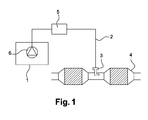
- the figure 1 illustrates an exemplary embodiment of an SCR system.
- SCR system is meant a system for the catalytic reduction of NOx in the exhaust gases of an internal combustion engine, preferably a vehicle, using, for example, urea as an ammonia precursor liquid.
- the SCR system comprises an additive tank 1 containing an aqueous solution of urea at 32.5% by weight of urea (eutectic), a pump 6 disposed inside the tank 1, a purge device 5 connected to the pump 6, and an injection channel 2 (or injection line) from the purge device 5 to an injector 3 located at an exhaust pipe 4.
- the pump 6 is a unidirectional pump.
- the pump 6 may be a bidirectional pump.
- the pump 6 In normal operating mode (injection of additive), the pump 6 causes a flow of additive from the tank 1 to the injector 3, via the purge device 5 and the injection channel 2, and this additive is injected into the exhaust gas by means of the injector 3.
- the purge device 5 is configured to let the additive supplied by the pump 6 to the injection channel 2.
- a purge the pump 6 is stopped and the purge device 5 sucks the additive contained in the injector and in the injection channel 2.
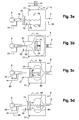
- the purge device 5 comprises a housing 51 delimiting a chamber 52 in which is housed a movable piston assembly (53, 54).
- the housing 51 includes an input port 55 and an output port 56.
- the moving element (53, 54) is slidably mounted in the chamber 52.
- the chamber 52 communicates with the pump 6 via the inlet port 55.
- the chamber 52 also communicates with the injection channel 2 via the exit port 56.
- the moving assembly (53, 54) is capable of a forward race in a first direction of oul ordinance (represented by the arrow numbered S1) and a return stroke in a second direction of sliding (represented by the arrow numbered S2).
- the moving element comprises a piston 54 slidably mounted in the chamber against a spring 53.
- the spring 53 comprises an end secured to the piston 54 and another end secured to the housing 51.
- the piston 54 is sealed. On the figure 2a the piston 54 occupies a position where it blocks the fluid communication between the input port 55 and the output port 56.
- the additive enters the chamber 52, via the inlet port 55, and pushes the piston 54 in the first direction of sliding (S1).
- the displacement of the piston 54 in the first direction of sliding (S1) causes the contraction of the spring 53 (the spring accumulates energy).
- the piston 54 is moved to a position where it releases the fluid communication between the input port 55 and the output port 56.
- the additive can therefore flow to the injection channel 2, via the chamber 52.
- the passage taken by the additive then consists of a portion of the chamber 52 and the output port 56.
- This flow of additive is schematically represented on the figure 2b by the arrow 61.
- the spring 53 is compressed and the piston 54 delimits a first volume V1 and a second volume V2 in the chamber 52.
- the pump 6 has a leakage rate.
- the pump 6 may have a leakage rate of 5 bar between 0.10 l / h and 0.80 l / h.
- the purge device 5 comprises a housing 71 provided with an inlet port 75 and an outlet port 76.
- the housing 71 comprises a first chamber 72 in which is housed a movable piston assembly (73, 74). .
- the moving element comprises a piston 74 slidably mounted in the first chamber 72 against a spring 73.
- the piston 74 is capable of making a forward stroke in a first direction of sliding (represented by the arrow numbered S11) and a return stroke in a second direction of sliding (represented by the arrow numbered S12).
- the first chamber 72 communicates with the pump 6 via the input port 75.
- the housing 71 also includes a second chamber 77. A portion of the first chamber 72 extends within the second chamber 77.
- the first chamber 72 communicates with the second chamber 77 via orifices 78.
- the second chamber 77 communicates with the injection channel 2 via the outlet port 76.
- the second chamber 77 may also be a part of the channel. injection 2.
- the SCR system comprises a bypass line 79 allowing an additive return to the tank.
- the bypass line 79 is provided with a calibrated orifice (not shown).
- the pump 6 may further have a leakage rate.
- the pump 6 may alternatively have no leakage flow.
- the piston 74 is sealed. On the figure 3a the piston 74 occupies a position where it blocks the fluid communication between the first chamber 72 and the second chamber 77.
- the additive When the pump 6 is started, the additive enters the first chamber 72, via the inlet port 75, and pushes the piston 74 in the first direction of sliding (S11).
- the displacement of the piston 74 in the first direction of sliding (S11) causes the contraction of the spring 73 (the spring accumulates energy).
- the pump 6 (which is running) distributes the additive of the tank.
- the piston 74 is subjected to a thrust force exerted by the additive distribution.
- the piston 74 is then moved in the first direction of sliding (S11).
- the piston 74 is moved to a position where it releases the fluid communication between the first chamber 72 and the second chamber 77.
- the additive can therefore flow to the injection channel 2, via the first 72 and second 77 chambers. .
- the passage taken by the additive then consists of a portion of the first chamber 72, the orifices 78, a portion of the second chamber 77, and the outlet port 76.
- This additive circulation is schematically represented on the figure 3b by arrows 81 and 82. As illustrated, the spring 73 is compressed.
- the pump 6 In order to initiate the purge, the pump 6 is stopped. As the piston 74 is no longer subjected to the thrust force exerted by the additive distribution, the spring 73 tends to return to its original shape (the spring restores the energy accumulated). The piston 74 is then moved (under the spring biasing action) following the second sliding direction (S12). This displacement is made possible by the bypass line 79. Indeed, such a bypass line 79 allows the return into the tank of the additive contained in the first chamber 72 (in the case where the pump 6 does not have a leakage rate). This additive return is schematically represented on the figure 3c by the arrow 83.
- the purge device of the invention implements mechanical means of great simplicity, inexpensive and reliable.
Landscapes
- Engineering & Computer Science (AREA)
- Chemical & Material Sciences (AREA)
- Chemical Kinetics & Catalysis (AREA)
- Health & Medical Sciences (AREA)
- Toxicology (AREA)
- Combustion & Propulsion (AREA)
- Mechanical Engineering (AREA)
- General Engineering & Computer Science (AREA)
- Exhaust Gas After Treatment (AREA)
Applications Claiming Priority (1)
| Application Number | Priority Date | Filing Date | Title |
|---|---|---|---|
| FR1261346A FR2998615A1 (fr) | 2012-11-28 | 2012-11-28 | Systeme scr et methode pour sa purge. |
Publications (2)
| Publication Number | Publication Date |
|---|---|
| EP2738366A1 true EP2738366A1 (de) | 2014-06-04 |
| EP2738366B1 EP2738366B1 (de) | 2015-10-21 |
Family
ID=47714314
Family Applications (1)
| Application Number | Title | Priority Date | Filing Date |
|---|---|---|---|
| EP13194064.5A Not-in-force EP2738366B1 (de) | 2012-11-28 | 2013-11-22 | SCR-System und Verfahren zu dessen Spülung |
Country Status (4)
| Country | Link |
|---|---|
| US (1) | US9353660B2 (de) |
| EP (1) | EP2738366B1 (de) |
| CN (1) | CN103850761A (de) |
| FR (1) | FR2998615A1 (de) |
Families Citing this family (8)
| Publication number | Priority date | Publication date | Assignee | Title |
|---|---|---|---|---|
| JP6369484B2 (ja) * | 2016-02-17 | 2018-08-08 | トヨタ自動車株式会社 | 内燃機関の排気浄化装置 |
| SG11201810698SA (en) * | 2016-05-31 | 2018-12-28 | Transocean Innovation Labs Ltd | Methods for assessing the reliability of hydraulically-actuated devices and related systems |
| US12305502B2 (en) | 2016-05-31 | 2025-05-20 | Transocean Innovation Labs Ltd. | Methods for assessing the reliability of hydraulically-actuated devices and related systems |
| DE102016118043A1 (de) | 2016-09-23 | 2018-03-29 | Eberspächer Exhaust Technology GmbH & Co. KG | Abgasreinigungseinrichtung und Düse für dieselbe |
| US10378415B2 (en) * | 2017-08-30 | 2019-08-13 | Caterpillar Inc. | Diagnostic and mitigation strategy for reductant injector obstruction in exhaust system |
| US10408108B2 (en) | 2018-01-30 | 2019-09-10 | Cummins Emission Solutions Inc. | Systems and methods for using liquid anhydrous ammonia as a reductant |
| US11406096B2 (en) * | 2019-06-13 | 2022-08-09 | Cnh Industrial America Llc | Sprayer boom charging system |
| US11143074B2 (en) | 2019-07-30 | 2021-10-12 | Delphi Technologies Ip Limited | Reagent dosing system and method |
Citations (4)
| Publication number | Priority date | Publication date | Assignee | Title |
|---|---|---|---|---|
| DE102008009650A1 (de) * | 2008-02-18 | 2009-08-27 | Robert Bosch Gmbh | Störungssicheres System zur Schadstoffverminderung |
| DE102008000594A1 (de) * | 2008-03-11 | 2009-09-17 | Robert Bosch Gmbh | Vorrichtung zum Entleeren einer Reduktionsmittelvorrichtung einer Brennkraftmaschine |
| EP2447490A1 (de) * | 2010-10-29 | 2012-05-02 | Hanspeter Mayer | Vorrichtung zur selektiven katalytischen Reduktion von Stickoxiden in einem Abgastrakt eines Kraftfahrzeuges |
| DE102011014026A1 (de) * | 2011-03-15 | 2012-09-20 | Albonair Gmbh | Reduktionsmitteleinspritzdüse |
Family Cites Families (4)
| Publication number | Priority date | Publication date | Assignee | Title |
|---|---|---|---|---|
| EP3421744B1 (de) * | 2005-12-22 | 2022-05-04 | Emitec Denmark A/S | Fluidtransfersystem und -verfahren |
| JP4804242B2 (ja) * | 2006-06-26 | 2011-11-02 | Udトラックス株式会社 | エンジンの排気浄化装置 |
| FR2942511B1 (fr) * | 2009-02-23 | 2015-04-17 | Coutier Moulage Gen Ind | Dispositif d'injection d'un produit additif dans le systeme d'echappement d'un vehicule automobile. |
| DE102012204385B4 (de) * | 2012-03-20 | 2024-05-16 | Robert Bosch Gmbh | Verfahren und Steuereinheit zur Dosierung von Kraftstoff in einen Abgaskanal |
-
2012
- 2012-11-28 FR FR1261346A patent/FR2998615A1/fr active Pending
-
2013
- 2013-11-22 EP EP13194064.5A patent/EP2738366B1/de not_active Not-in-force
- 2013-11-25 US US14/089,068 patent/US9353660B2/en not_active Expired - Fee Related
- 2013-11-27 CN CN201310616726.3A patent/CN103850761A/zh active Pending
Patent Citations (4)
| Publication number | Priority date | Publication date | Assignee | Title |
|---|---|---|---|---|
| DE102008009650A1 (de) * | 2008-02-18 | 2009-08-27 | Robert Bosch Gmbh | Störungssicheres System zur Schadstoffverminderung |
| DE102008000594A1 (de) * | 2008-03-11 | 2009-09-17 | Robert Bosch Gmbh | Vorrichtung zum Entleeren einer Reduktionsmittelvorrichtung einer Brennkraftmaschine |
| EP2447490A1 (de) * | 2010-10-29 | 2012-05-02 | Hanspeter Mayer | Vorrichtung zur selektiven katalytischen Reduktion von Stickoxiden in einem Abgastrakt eines Kraftfahrzeuges |
| DE102011014026A1 (de) * | 2011-03-15 | 2012-09-20 | Albonair Gmbh | Reduktionsmitteleinspritzdüse |
Also Published As
| Publication number | Publication date |
|---|---|
| US9353660B2 (en) | 2016-05-31 |
| EP2738366B1 (de) | 2015-10-21 |
| FR2998615A1 (fr) | 2014-05-30 |
| US20140182271A1 (en) | 2014-07-03 |
| CN103850761A (zh) | 2014-06-11 |
Similar Documents
| Publication | Publication Date | Title |
|---|---|---|
| EP2738366B1 (de) | SCR-System und Verfahren zu dessen Spülung | |
| FR2921105A1 (fr) | Systeme scr et methode pour sa purge | |
| FR2879239A1 (fr) | Systeme de stockage et d'injection d'un additif dans des gaz d'echappement d'un moteur | |
| FR2942511A1 (fr) | Dispositif d'injection d'un produit additif dans le systeme d'echappement d'un vehicule automobile. | |
| EP3080454B1 (de) | Pumpe für additiv | |
| FR2921911A1 (fr) | Systeme de stockage et d'injection d'une solution d'additif dans des gaz d'echappement d'un moteur. | |
| EP1771649A1 (de) | Verfahren und vorrichtung zur verstärkung eines rohrförmigen einlasses eines turbomotors mit druckluft | |
| FR2951775A1 (fr) | Dispositif d'injection d'un produit additif dans une ligne de traitement | |
| WO2019063368A1 (fr) | Procédé de réduction catalytique sélective avec désorption d'ammoniac à partir d'une cartouche dans une ligne d'échappement | |
| WO2011027059A1 (fr) | Dispositif d'injection de reducteur pour une reduction catalytique selective et ensemble comportant un moteur et une ligne d'echappement muni d'un tel dispositf d'injection | |
| FR2973438A1 (fr) | Dispositif pour remplir un reservoir de vehicule automobile | |
| EP2851529A1 (de) | Reinigungsverfahren eines Systems mit selektiver katalytischer Reduktion | |
| EP2434119B1 (de) | Ansaugverfahren eines Systems mit selektiver katalytischer Reduktion für ein Fahrzeugsystem und entsprechendes Fahrzeug | |
| FR3048720A1 (fr) | Procede d'optimisation de la consommation d'agent reducteur dans une ligne d'echappement d'un vehicule automobile | |
| FR2936011A1 (fr) | Installation de traitement des polluants contenus dans des gaz d'echappement d'un moteur a combustion interne et procede utilisant une telle installation | |
| FR3010733A1 (fr) | Procede de pilotage d'un injecteur dispose dans une ligne d'echappement d'un vehicule automobile | |
| WO2011131882A1 (fr) | Procede de controle de purge d'un systeme de reduction catalytique selective | |
| FR2918111A1 (fr) | Systeme de stockage et d'injection d'un additif dans des gaz d'echappement d'un moteur. | |
| FR2889259A3 (fr) | Rampe commune d'alimentation en carburant pour vehicule a pression variable | |
| EP3418517A1 (de) | Motorantriebsanlage, die mit einer leistungsfähigen luftreinigungsvorrichtung ausgestattet ist, und entsprechendes steuerverfahren | |
| EP2694786B1 (de) | Verfahren zur bestimmung der öffnungsdauer einer öffnung | |
| FR2991380A1 (fr) | Systeme de dosage d'un agent reducteur pour un dispositif de depollution des gaz d'echappement d'un moteur a combustion | |
| FR3022305A1 (fr) | Dispositif de pompe, notamment pour alimenter en agent reducteur liquide un systeme de post-traitement des gaz d'echappement | |
| WO2021009466A1 (fr) | Systeme d'injection hydraulique a came | |
| EP3290669A1 (de) | Verfahren zur steuerung eines systems zur nachbehandlung von abgasen vom typ scr für dessen frostschutz bei aktiviertem modus, und system zur umsetzung dieses verfahrens |
Legal Events
| Date | Code | Title | Description |
|---|---|---|---|
| PUAI | Public reference made under article 153(3) epc to a published international application that has entered the european phase |
Free format text: ORIGINAL CODE: 0009012 |
|
| 17P | Request for examination filed |
Effective date: 20131122 |
|
| AK | Designated contracting states |
Kind code of ref document: A1 Designated state(s): AL AT BE BG CH CY CZ DE DK EE ES FI FR GB GR HR HU IE IS IT LI LT LU LV MC MK MT NL NO PL PT RO RS SE SI SK SM TR |
|
| AX | Request for extension of the european patent |
Extension state: BA ME |
|
| R17P | Request for examination filed (corrected) |
Effective date: 20141204 |
|
| RBV | Designated contracting states (corrected) |
Designated state(s): AL AT BE BG CH CY CZ DE DK EE ES FI FR GB GR HR HU IE IS IT LI LT LU LV MC MK MT NL NO PL PT RO RS SE SI SK SM TR |
|
| REG | Reference to a national code |
Ref country code: DE Ref legal event code: R079 Ref document number: 602013003556 Country of ref document: DE Free format text: PREVIOUS MAIN CLASS: F01N0003200000 Ipc: F01N0003100000 |
|
| GRAP | Despatch of communication of intention to grant a patent |
Free format text: ORIGINAL CODE: EPIDOSNIGR1 |
|
| RIC1 | Information provided on ipc code assigned before grant |
Ipc: F01N 3/20 20060101ALI20150429BHEP Ipc: F01N 3/10 20060101AFI20150429BHEP |
|
| INTG | Intention to grant announced |
Effective date: 20150515 |
|
| GRAS | Grant fee paid |
Free format text: ORIGINAL CODE: EPIDOSNIGR3 |
|
| GRAA | (expected) grant |
Free format text: ORIGINAL CODE: 0009210 |
|
| AK | Designated contracting states |
Kind code of ref document: B1 Designated state(s): AL AT BE BG CH CY CZ DE DK EE ES FI FR GB GR HR HU IE IS IT LI LT LU LV MC MK MT NL NO PL PT RO RS SE SI SK SM TR |
|
| REG | Reference to a national code |
Ref country code: GB Ref legal event code: FG4D Free format text: NOT ENGLISH Ref country code: NL Ref legal event code: MP Effective date: 20151021 |
|
| REG | Reference to a national code |
Ref country code: CH Ref legal event code: EP |
|
| REG | Reference to a national code |
Ref country code: AT Ref legal event code: REF Ref document number: 756758 Country of ref document: AT Kind code of ref document: T Effective date: 20151115 |
|
| REG | Reference to a national code |
Ref country code: IE Ref legal event code: FG4D Free format text: LANGUAGE OF EP DOCUMENT: FRENCH |
|
| REG | Reference to a national code |
Ref country code: DE Ref legal event code: R096 Ref document number: 602013003556 Country of ref document: DE |
|
| REG | Reference to a national code |
Ref country code: FR Ref legal event code: PLFP Year of fee payment: 3 |
|
| REG | Reference to a national code |
Ref country code: LT Ref legal event code: MG4D |
|
| REG | Reference to a national code |
Ref country code: AT Ref legal event code: MK05 Ref document number: 756758 Country of ref document: AT Kind code of ref document: T Effective date: 20151021 |
|
| PG25 | Lapsed in a contracting state [announced via postgrant information from national office to epo] |
Ref country code: NL Free format text: LAPSE BECAUSE OF FAILURE TO SUBMIT A TRANSLATION OF THE DESCRIPTION OR TO PAY THE FEE WITHIN THE PRESCRIBED TIME-LIMIT Effective date: 20151021 Ref country code: ES Free format text: LAPSE BECAUSE OF FAILURE TO SUBMIT A TRANSLATION OF THE DESCRIPTION OR TO PAY THE FEE WITHIN THE PRESCRIBED TIME-LIMIT Effective date: 20151021 Ref country code: NO Free format text: LAPSE BECAUSE OF FAILURE TO SUBMIT A TRANSLATION OF THE DESCRIPTION OR TO PAY THE FEE WITHIN THE PRESCRIBED TIME-LIMIT Effective date: 20160121 Ref country code: IT Free format text: LAPSE BECAUSE OF FAILURE TO SUBMIT A TRANSLATION OF THE DESCRIPTION OR TO PAY THE FEE WITHIN THE PRESCRIBED TIME-LIMIT Effective date: 20151021 Ref country code: LT Free format text: LAPSE BECAUSE OF FAILURE TO SUBMIT A TRANSLATION OF THE DESCRIPTION OR TO PAY THE FEE WITHIN THE PRESCRIBED TIME-LIMIT Effective date: 20151021 Ref country code: HR Free format text: LAPSE BECAUSE OF FAILURE TO SUBMIT A TRANSLATION OF THE DESCRIPTION OR TO PAY THE FEE WITHIN THE PRESCRIBED TIME-LIMIT Effective date: 20151021 Ref country code: IS Free format text: LAPSE BECAUSE OF FAILURE TO SUBMIT A TRANSLATION OF THE DESCRIPTION OR TO PAY THE FEE WITHIN THE PRESCRIBED TIME-LIMIT Effective date: 20160221 |
|
| PG25 | Lapsed in a contracting state [announced via postgrant information from national office to epo] |
Ref country code: LV Free format text: LAPSE BECAUSE OF FAILURE TO SUBMIT A TRANSLATION OF THE DESCRIPTION OR TO PAY THE FEE WITHIN THE PRESCRIBED TIME-LIMIT Effective date: 20151021 Ref country code: AT Free format text: LAPSE BECAUSE OF FAILURE TO SUBMIT A TRANSLATION OF THE DESCRIPTION OR TO PAY THE FEE WITHIN THE PRESCRIBED TIME-LIMIT Effective date: 20151021 Ref country code: RS Free format text: LAPSE BECAUSE OF FAILURE TO SUBMIT A TRANSLATION OF THE DESCRIPTION OR TO PAY THE FEE WITHIN THE PRESCRIBED TIME-LIMIT Effective date: 20151021 Ref country code: GR Free format text: LAPSE BECAUSE OF FAILURE TO SUBMIT A TRANSLATION OF THE DESCRIPTION OR TO PAY THE FEE WITHIN THE PRESCRIBED TIME-LIMIT Effective date: 20160122 Ref country code: PL Free format text: LAPSE BECAUSE OF FAILURE TO SUBMIT A TRANSLATION OF THE DESCRIPTION OR TO PAY THE FEE WITHIN THE PRESCRIBED TIME-LIMIT Effective date: 20151021 Ref country code: SE Free format text: LAPSE BECAUSE OF FAILURE TO SUBMIT A TRANSLATION OF THE DESCRIPTION OR TO PAY THE FEE WITHIN THE PRESCRIBED TIME-LIMIT Effective date: 20151021 Ref country code: FI Free format text: LAPSE BECAUSE OF FAILURE TO SUBMIT A TRANSLATION OF THE DESCRIPTION OR TO PAY THE FEE WITHIN THE PRESCRIBED TIME-LIMIT Effective date: 20151021 Ref country code: PT Free format text: LAPSE BECAUSE OF FAILURE TO SUBMIT A TRANSLATION OF THE DESCRIPTION OR TO PAY THE FEE WITHIN THE PRESCRIBED TIME-LIMIT Effective date: 20160222 |
|
| REG | Reference to a national code |
Ref country code: DE Ref legal event code: R097 Ref document number: 602013003556 Country of ref document: DE |
|
| PG25 | Lapsed in a contracting state [announced via postgrant information from national office to epo] |
Ref country code: CZ Free format text: LAPSE BECAUSE OF FAILURE TO SUBMIT A TRANSLATION OF THE DESCRIPTION OR TO PAY THE FEE WITHIN THE PRESCRIBED TIME-LIMIT Effective date: 20151021 Ref country code: MC Free format text: LAPSE BECAUSE OF FAILURE TO SUBMIT A TRANSLATION OF THE DESCRIPTION OR TO PAY THE FEE WITHIN THE PRESCRIBED TIME-LIMIT Effective date: 20151021 |
|
| REG | Reference to a national code |
Ref country code: IE Ref legal event code: MM4A |
|
| PLBE | No opposition filed within time limit |
Free format text: ORIGINAL CODE: 0009261 |
|
| STAA | Information on the status of an ep patent application or granted ep patent |
Free format text: STATUS: NO OPPOSITION FILED WITHIN TIME LIMIT |
|
| PG25 | Lapsed in a contracting state [announced via postgrant information from national office to epo] |
Ref country code: DK Free format text: LAPSE BECAUSE OF FAILURE TO SUBMIT A TRANSLATION OF THE DESCRIPTION OR TO PAY THE FEE WITHIN THE PRESCRIBED TIME-LIMIT Effective date: 20151021 Ref country code: SK Free format text: LAPSE BECAUSE OF FAILURE TO SUBMIT A TRANSLATION OF THE DESCRIPTION OR TO PAY THE FEE WITHIN THE PRESCRIBED TIME-LIMIT Effective date: 20151021 Ref country code: EE Free format text: LAPSE BECAUSE OF FAILURE TO SUBMIT A TRANSLATION OF THE DESCRIPTION OR TO PAY THE FEE WITHIN THE PRESCRIBED TIME-LIMIT Effective date: 20151021 Ref country code: RO Free format text: LAPSE BECAUSE OF FAILURE TO SUBMIT A TRANSLATION OF THE DESCRIPTION OR TO PAY THE FEE WITHIN THE PRESCRIBED TIME-LIMIT Effective date: 20151021 Ref country code: SM Free format text: LAPSE BECAUSE OF FAILURE TO SUBMIT A TRANSLATION OF THE DESCRIPTION OR TO PAY THE FEE WITHIN THE PRESCRIBED TIME-LIMIT Effective date: 20151021 |
|
| 26N | No opposition filed |
Effective date: 20160722 |
|
| PG25 | Lapsed in a contracting state [announced via postgrant information from national office to epo] |
Ref country code: IE Free format text: LAPSE BECAUSE OF NON-PAYMENT OF DUE FEES Effective date: 20151122 |
|
| REG | Reference to a national code |
Ref country code: FR Ref legal event code: PLFP Year of fee payment: 4 |
|
| PG25 | Lapsed in a contracting state [announced via postgrant information from national office to epo] |
Ref country code: SI Free format text: LAPSE BECAUSE OF FAILURE TO SUBMIT A TRANSLATION OF THE DESCRIPTION OR TO PAY THE FEE WITHIN THE PRESCRIBED TIME-LIMIT Effective date: 20151021 |
|
| PGFP | Annual fee paid to national office [announced via postgrant information from national office to epo] |
Ref country code: DE Payment date: 20161121 Year of fee payment: 4 Ref country code: FR Payment date: 20161128 Year of fee payment: 4 |
|
| PG25 | Lapsed in a contracting state [announced via postgrant information from national office to epo] |
Ref country code: BG Free format text: LAPSE BECAUSE OF FAILURE TO SUBMIT A TRANSLATION OF THE DESCRIPTION OR TO PAY THE FEE WITHIN THE PRESCRIBED TIME-LIMIT Effective date: 20151021 Ref country code: HU Free format text: LAPSE BECAUSE OF FAILURE TO SUBMIT A TRANSLATION OF THE DESCRIPTION OR TO PAY THE FEE WITHIN THE PRESCRIBED TIME-LIMIT; INVALID AB INITIO Effective date: 20131122 |
|
| PG25 | Lapsed in a contracting state [announced via postgrant information from national office to epo] |
Ref country code: CY Free format text: LAPSE BECAUSE OF FAILURE TO SUBMIT A TRANSLATION OF THE DESCRIPTION OR TO PAY THE FEE WITHIN THE PRESCRIBED TIME-LIMIT Effective date: 20151021 |
|
| REG | Reference to a national code |
Ref country code: CH Ref legal event code: PL |
|
| PG25 | Lapsed in a contracting state [announced via postgrant information from national office to epo] |
Ref country code: LI Free format text: LAPSE BECAUSE OF NON-PAYMENT OF DUE FEES Effective date: 20161130 Ref country code: CH Free format text: LAPSE BECAUSE OF NON-PAYMENT OF DUE FEES Effective date: 20161130 Ref country code: BE Free format text: LAPSE BECAUSE OF NON-PAYMENT OF DUE FEES Effective date: 20151130 |
|
| PG25 | Lapsed in a contracting state [announced via postgrant information from national office to epo] |
Ref country code: MT Free format text: LAPSE BECAUSE OF FAILURE TO SUBMIT A TRANSLATION OF THE DESCRIPTION OR TO PAY THE FEE WITHIN THE PRESCRIBED TIME-LIMIT Effective date: 20151021 |
|
| PG25 | Lapsed in a contracting state [announced via postgrant information from national office to epo] |
Ref country code: LU Free format text: LAPSE BECAUSE OF NON-PAYMENT OF DUE FEES Effective date: 20151122 |
|
| REG | Reference to a national code |
Ref country code: DE Ref legal event code: R119 Ref document number: 602013003556 Country of ref document: DE |
|
| PG25 | Lapsed in a contracting state [announced via postgrant information from national office to epo] |
Ref country code: MK Free format text: LAPSE BECAUSE OF FAILURE TO SUBMIT A TRANSLATION OF THE DESCRIPTION OR TO PAY THE FEE WITHIN THE PRESCRIBED TIME-LIMIT Effective date: 20151021 |
|
| GBPC | Gb: european patent ceased through non-payment of renewal fee |
Effective date: 20171122 |
|
| REG | Reference to a national code |
Ref country code: FR Ref legal event code: ST Effective date: 20180731 |
|
| PG25 | Lapsed in a contracting state [announced via postgrant information from national office to epo] |
Ref country code: TR Free format text: LAPSE BECAUSE OF FAILURE TO SUBMIT A TRANSLATION OF THE DESCRIPTION OR TO PAY THE FEE WITHIN THE PRESCRIBED TIME-LIMIT Effective date: 20151021 Ref country code: AL Free format text: LAPSE BECAUSE OF FAILURE TO SUBMIT A TRANSLATION OF THE DESCRIPTION OR TO PAY THE FEE WITHIN THE PRESCRIBED TIME-LIMIT Effective date: 20151021 Ref country code: DE Free format text: LAPSE BECAUSE OF NON-PAYMENT OF DUE FEES Effective date: 20180602 Ref country code: FR Free format text: LAPSE BECAUSE OF NON-PAYMENT OF DUE FEES Effective date: 20171130 |
|
| PG25 | Lapsed in a contracting state [announced via postgrant information from national office to epo] |
Ref country code: GB Free format text: LAPSE BECAUSE OF NON-PAYMENT OF DUE FEES Effective date: 20171122 |