EP2737965A1 - Method for manufacturing a metallic component by additive laser manufacturing - Google Patents
Method for manufacturing a metallic component by additive laser manufacturing Download PDFInfo
- Publication number
- EP2737965A1 EP2737965A1 EP12008074.2A EP12008074A EP2737965A1 EP 2737965 A1 EP2737965 A1 EP 2737965A1 EP 12008074 A EP12008074 A EP 12008074A EP 2737965 A1 EP2737965 A1 EP 2737965A1
- Authority
- EP
- European Patent Office
- Prior art keywords
- component
- powder
- article
- layer
- grain orientation
- Prior art date
- Legal status (The legal status is an assumption and is not a legal conclusion. Google has not performed a legal analysis and makes no representation as to the accuracy of the status listed.)
- Withdrawn
Links
Images





Classifications
-
- F—MECHANICAL ENGINEERING; LIGHTING; HEATING; WEAPONS; BLASTING
- F01—MACHINES OR ENGINES IN GENERAL; ENGINE PLANTS IN GENERAL; STEAM ENGINES
- F01D—NON-POSITIVE DISPLACEMENT MACHINES OR ENGINES, e.g. STEAM TURBINES
- F01D5/00—Blades; Blade-carrying members; Heating, heat-insulating, cooling or antivibration means on the blades or the members
- F01D5/005—Repairing methods or devices
-
- B—PERFORMING OPERATIONS; TRANSPORTING
- B22—CASTING; POWDER METALLURGY
- B22F—WORKING METALLIC POWDER; MANUFACTURE OF ARTICLES FROM METALLIC POWDER; MAKING METALLIC POWDER; APPARATUS OR DEVICES SPECIALLY ADAPTED FOR METALLIC POWDER
- B22F3/00—Manufacture of workpieces or articles from metallic powder characterised by the manner of compacting or sintering; Apparatus specially adapted therefor ; Presses and furnaces
- B22F3/10—Sintering only
- B22F3/105—Sintering only by using electric current other than for infrared radiant energy, laser radiation or plasma ; by ultrasonic bonding
-
- B—PERFORMING OPERATIONS; TRANSPORTING
- B22—CASTING; POWDER METALLURGY
- B22F—WORKING METALLIC POWDER; MANUFACTURE OF ARTICLES FROM METALLIC POWDER; MAKING METALLIC POWDER; APPARATUS OR DEVICES SPECIALLY ADAPTED FOR METALLIC POWDER
- B22F10/00—Additive manufacturing of workpieces or articles from metallic powder
- B22F10/20—Direct sintering or melting
- B22F10/28—Powder bed fusion, e.g. selective laser melting [SLM] or electron beam melting [EBM]
-
- B—PERFORMING OPERATIONS; TRANSPORTING
- B22—CASTING; POWDER METALLURGY
- B22F—WORKING METALLIC POWDER; MANUFACTURE OF ARTICLES FROM METALLIC POWDER; MAKING METALLIC POWDER; APPARATUS OR DEVICES SPECIALLY ADAPTED FOR METALLIC POWDER
- B22F10/00—Additive manufacturing of workpieces or articles from metallic powder
- B22F10/30—Process control
- B22F10/34—Process control of powder characteristics, e.g. density, oxidation or flowability
-
- B—PERFORMING OPERATIONS; TRANSPORTING
- B22—CASTING; POWDER METALLURGY
- B22F—WORKING METALLIC POWDER; MANUFACTURE OF ARTICLES FROM METALLIC POWDER; MAKING METALLIC POWDER; APPARATUS OR DEVICES SPECIALLY ADAPTED FOR METALLIC POWDER
- B22F10/00—Additive manufacturing of workpieces or articles from metallic powder
- B22F10/30—Process control
- B22F10/36—Process control of energy beam parameters
- B22F10/366—Scanning parameters, e.g. hatch distance or scanning strategy
-
- B—PERFORMING OPERATIONS; TRANSPORTING
- B22—CASTING; POWDER METALLURGY
- B22F—WORKING METALLIC POWDER; MANUFACTURE OF ARTICLES FROM METALLIC POWDER; MAKING METALLIC POWDER; APPARATUS OR DEVICES SPECIALLY ADAPTED FOR METALLIC POWDER
- B22F10/00—Additive manufacturing of workpieces or articles from metallic powder
- B22F10/30—Process control
- B22F10/38—Process control to achieve specific product aspects, e.g. surface smoothness, density, porosity or hollow structures
-
- B—PERFORMING OPERATIONS; TRANSPORTING
- B22—CASTING; POWDER METALLURGY
- B22F—WORKING METALLIC POWDER; MANUFACTURE OF ARTICLES FROM METALLIC POWDER; MAKING METALLIC POWDER; APPARATUS OR DEVICES SPECIALLY ADAPTED FOR METALLIC POWDER
- B22F7/00—Manufacture of composite layers, workpieces, or articles, comprising metallic powder, by sintering the powder, with or without compacting wherein at least one part is obtained by sintering or compression
-
- B—PERFORMING OPERATIONS; TRANSPORTING
- B23—MACHINE TOOLS; METAL-WORKING NOT OTHERWISE PROVIDED FOR
- B23K—SOLDERING OR UNSOLDERING; WELDING; CLADDING OR PLATING BY SOLDERING OR WELDING; CUTTING BY APPLYING HEAT LOCALLY, e.g. FLAME CUTTING; WORKING BY LASER BEAM
- B23K15/00—Electron-beam welding or cutting
- B23K15/0046—Welding
- B23K15/0086—Welding welding for purposes other than joining, e.g. build-up welding
-
- B—PERFORMING OPERATIONS; TRANSPORTING
- B23—MACHINE TOOLS; METAL-WORKING NOT OTHERWISE PROVIDED FOR
- B23K—SOLDERING OR UNSOLDERING; WELDING; CLADDING OR PLATING BY SOLDERING OR WELDING; CUTTING BY APPLYING HEAT LOCALLY, e.g. FLAME CUTTING; WORKING BY LASER BEAM
- B23K26/00—Working by laser beam, e.g. welding, cutting or boring
- B23K26/08—Devices involving relative movement between laser beam and workpiece
-
- B—PERFORMING OPERATIONS; TRANSPORTING
- B23—MACHINE TOOLS; METAL-WORKING NOT OTHERWISE PROVIDED FOR
- B23K—SOLDERING OR UNSOLDERING; WELDING; CLADDING OR PLATING BY SOLDERING OR WELDING; CUTTING BY APPLYING HEAT LOCALLY, e.g. FLAME CUTTING; WORKING BY LASER BEAM
- B23K26/00—Working by laser beam, e.g. welding, cutting or boring
- B23K26/20—Bonding
- B23K26/32—Bonding taking account of the properties of the material involved
-
- B—PERFORMING OPERATIONS; TRANSPORTING
- B23—MACHINE TOOLS; METAL-WORKING NOT OTHERWISE PROVIDED FOR
- B23K—SOLDERING OR UNSOLDERING; WELDING; CLADDING OR PLATING BY SOLDERING OR WELDING; CUTTING BY APPLYING HEAT LOCALLY, e.g. FLAME CUTTING; WORKING BY LASER BEAM
- B23K26/00—Working by laser beam, e.g. welding, cutting or boring
- B23K26/34—Laser welding for purposes other than joining
- B23K26/342—Build-up welding
-
- B—PERFORMING OPERATIONS; TRANSPORTING
- B23—MACHINE TOOLS; METAL-WORKING NOT OTHERWISE PROVIDED FOR
- B23K—SOLDERING OR UNSOLDERING; WELDING; CLADDING OR PLATING BY SOLDERING OR WELDING; CUTTING BY APPLYING HEAT LOCALLY, e.g. FLAME CUTTING; WORKING BY LASER BEAM
- B23K35/00—Rods, electrodes, materials, or media, for use in soldering, welding, or cutting
- B23K35/02—Rods, electrodes, materials, or media, for use in soldering, welding, or cutting characterised by mechanical features, e.g. shape
- B23K35/0255—Rods, electrodes, materials, or media, for use in soldering, welding, or cutting characterised by mechanical features, e.g. shape for use in welding
-
- B—PERFORMING OPERATIONS; TRANSPORTING
- B23—MACHINE TOOLS; METAL-WORKING NOT OTHERWISE PROVIDED FOR
- B23K—SOLDERING OR UNSOLDERING; WELDING; CLADDING OR PLATING BY SOLDERING OR WELDING; CUTTING BY APPLYING HEAT LOCALLY, e.g. FLAME CUTTING; WORKING BY LASER BEAM
- B23K35/00—Rods, electrodes, materials, or media, for use in soldering, welding, or cutting
- B23K35/02—Rods, electrodes, materials, or media, for use in soldering, welding, or cutting characterised by mechanical features, e.g. shape
- B23K35/0255—Rods, electrodes, materials, or media, for use in soldering, welding, or cutting characterised by mechanical features, e.g. shape for use in welding
- B23K35/0261—Rods, electrodes or wires
-
- B—PERFORMING OPERATIONS; TRANSPORTING
- B23—MACHINE TOOLS; METAL-WORKING NOT OTHERWISE PROVIDED FOR
- B23K—SOLDERING OR UNSOLDERING; WELDING; CLADDING OR PLATING BY SOLDERING OR WELDING; CUTTING BY APPLYING HEAT LOCALLY, e.g. FLAME CUTTING; WORKING BY LASER BEAM
- B23K35/00—Rods, electrodes, materials, or media, for use in soldering, welding, or cutting
- B23K35/02—Rods, electrodes, materials, or media, for use in soldering, welding, or cutting characterised by mechanical features, e.g. shape
- B23K35/0255—Rods, electrodes, materials, or media, for use in soldering, welding, or cutting characterised by mechanical features, e.g. shape for use in welding
- B23K35/0261—Rods, electrodes or wires
- B23K35/0272—Rods, electrodes or wires with more than one layer of coating or sheathing material
-
- B—PERFORMING OPERATIONS; TRANSPORTING
- B23—MACHINE TOOLS; METAL-WORKING NOT OTHERWISE PROVIDED FOR
- B23K—SOLDERING OR UNSOLDERING; WELDING; CLADDING OR PLATING BY SOLDERING OR WELDING; CUTTING BY APPLYING HEAT LOCALLY, e.g. FLAME CUTTING; WORKING BY LASER BEAM
- B23K35/00—Rods, electrodes, materials, or media, for use in soldering, welding, or cutting
- B23K35/22—Rods, electrodes, materials, or media, for use in soldering, welding, or cutting characterised by the composition or nature of the material
- B23K35/24—Selection of soldering or welding materials proper
- B23K35/30—Selection of soldering or welding materials proper with the principal constituent melting at less than 1550°C
-
- B—PERFORMING OPERATIONS; TRANSPORTING
- B23—MACHINE TOOLS; METAL-WORKING NOT OTHERWISE PROVIDED FOR
- B23K—SOLDERING OR UNSOLDERING; WELDING; CLADDING OR PLATING BY SOLDERING OR WELDING; CUTTING BY APPLYING HEAT LOCALLY, e.g. FLAME CUTTING; WORKING BY LASER BEAM
- B23K35/00—Rods, electrodes, materials, or media, for use in soldering, welding, or cutting
- B23K35/22—Rods, electrodes, materials, or media, for use in soldering, welding, or cutting characterised by the composition or nature of the material
- B23K35/24—Selection of soldering or welding materials proper
- B23K35/30—Selection of soldering or welding materials proper with the principal constituent melting at less than 1550°C
- B23K35/3033—Ni as the principal constituent
-
- B—PERFORMING OPERATIONS; TRANSPORTING
- B23—MACHINE TOOLS; METAL-WORKING NOT OTHERWISE PROVIDED FOR
- B23K—SOLDERING OR UNSOLDERING; WELDING; CLADDING OR PLATING BY SOLDERING OR WELDING; CUTTING BY APPLYING HEAT LOCALLY, e.g. FLAME CUTTING; WORKING BY LASER BEAM
- B23K35/00—Rods, electrodes, materials, or media, for use in soldering, welding, or cutting
- B23K35/22—Rods, electrodes, materials, or media, for use in soldering, welding, or cutting characterised by the composition or nature of the material
- B23K35/24—Selection of soldering or welding materials proper
- B23K35/30—Selection of soldering or welding materials proper with the principal constituent melting at less than 1550°C
- B23K35/3046—Co as the principal constituent
-
- B—PERFORMING OPERATIONS; TRANSPORTING
- B23—MACHINE TOOLS; METAL-WORKING NOT OTHERWISE PROVIDED FOR
- B23K—SOLDERING OR UNSOLDERING; WELDING; CLADDING OR PLATING BY SOLDERING OR WELDING; CUTTING BY APPLYING HEAT LOCALLY, e.g. FLAME CUTTING; WORKING BY LASER BEAM
- B23K35/00—Rods, electrodes, materials, or media, for use in soldering, welding, or cutting
- B23K35/22—Rods, electrodes, materials, or media, for use in soldering, welding, or cutting characterised by the composition or nature of the material
- B23K35/24—Selection of soldering or welding materials proper
- B23K35/30—Selection of soldering or welding materials proper with the principal constituent melting at less than 1550°C
- B23K35/3053—Fe as the principal constituent
-
- B—PERFORMING OPERATIONS; TRANSPORTING
- B23—MACHINE TOOLS; METAL-WORKING NOT OTHERWISE PROVIDED FOR
- B23K—SOLDERING OR UNSOLDERING; WELDING; CLADDING OR PLATING BY SOLDERING OR WELDING; CUTTING BY APPLYING HEAT LOCALLY, e.g. FLAME CUTTING; WORKING BY LASER BEAM
- B23K35/00—Rods, electrodes, materials, or media, for use in soldering, welding, or cutting
- B23K35/22—Rods, electrodes, materials, or media, for use in soldering, welding, or cutting characterised by the composition or nature of the material
- B23K35/38—Selection of media, e.g. special atmospheres for surrounding the working area
-
- B—PERFORMING OPERATIONS; TRANSPORTING
- B33—ADDITIVE MANUFACTURING TECHNOLOGY
- B33Y—ADDITIVE MANUFACTURING, i.e. MANUFACTURING OF THREE-DIMENSIONAL [3D] OBJECTS BY ADDITIVE DEPOSITION, ADDITIVE AGGLOMERATION OR ADDITIVE LAYERING, e.g. BY 3D PRINTING, STEREOLITHOGRAPHY OR SELECTIVE LASER SINTERING
- B33Y10/00—Processes of additive manufacturing
-
- B—PERFORMING OPERATIONS; TRANSPORTING
- B33—ADDITIVE MANUFACTURING TECHNOLOGY
- B33Y—ADDITIVE MANUFACTURING, i.e. MANUFACTURING OF THREE-DIMENSIONAL [3D] OBJECTS BY ADDITIVE DEPOSITION, ADDITIVE AGGLOMERATION OR ADDITIVE LAYERING, e.g. BY 3D PRINTING, STEREOLITHOGRAPHY OR SELECTIVE LASER SINTERING
- B33Y50/00—Data acquisition or data processing for additive manufacturing
-
- B—PERFORMING OPERATIONS; TRANSPORTING
- B33—ADDITIVE MANUFACTURING TECHNOLOGY
- B33Y—ADDITIVE MANUFACTURING, i.e. MANUFACTURING OF THREE-DIMENSIONAL [3D] OBJECTS BY ADDITIVE DEPOSITION, ADDITIVE AGGLOMERATION OR ADDITIVE LAYERING, e.g. BY 3D PRINTING, STEREOLITHOGRAPHY OR SELECTIVE LASER SINTERING
- B33Y70/00—Materials specially adapted for additive manufacturing
-
- F—MECHANICAL ENGINEERING; LIGHTING; HEATING; WEAPONS; BLASTING
- F01—MACHINES OR ENGINES IN GENERAL; ENGINE PLANTS IN GENERAL; STEAM ENGINES
- F01D—NON-POSITIVE DISPLACEMENT MACHINES OR ENGINES, e.g. STEAM TURBINES
- F01D5/00—Blades; Blade-carrying members; Heating, heat-insulating, cooling or antivibration means on the blades or the members
- F01D5/12—Blades
- F01D5/28—Selecting particular materials; Particular measures relating thereto; Measures against erosion or corrosion
-
- B—PERFORMING OPERATIONS; TRANSPORTING
- B22—CASTING; POWDER METALLURGY
- B22F—WORKING METALLIC POWDER; MANUFACTURE OF ARTICLES FROM METALLIC POWDER; MAKING METALLIC POWDER; APPARATUS OR DEVICES SPECIALLY ADAPTED FOR METALLIC POWDER
- B22F10/00—Additive manufacturing of workpieces or articles from metallic powder
- B22F10/60—Treatment of workpieces or articles after build-up
- B22F10/64—Treatment of workpieces or articles after build-up by thermal means
-
- B—PERFORMING OPERATIONS; TRANSPORTING
- B23—MACHINE TOOLS; METAL-WORKING NOT OTHERWISE PROVIDED FOR
- B23K—SOLDERING OR UNSOLDERING; WELDING; CLADDING OR PLATING BY SOLDERING OR WELDING; CUTTING BY APPLYING HEAT LOCALLY, e.g. FLAME CUTTING; WORKING BY LASER BEAM
- B23K2103/00—Materials to be soldered, welded or cut
- B23K2103/02—Iron or ferrous alloys
-
- B—PERFORMING OPERATIONS; TRANSPORTING
- B23—MACHINE TOOLS; METAL-WORKING NOT OTHERWISE PROVIDED FOR
- B23K—SOLDERING OR UNSOLDERING; WELDING; CLADDING OR PLATING BY SOLDERING OR WELDING; CUTTING BY APPLYING HEAT LOCALLY, e.g. FLAME CUTTING; WORKING BY LASER BEAM
- B23K2103/00—Materials to be soldered, welded or cut
- B23K2103/18—Dissimilar materials
- B23K2103/26—Alloys of Nickel and Cobalt and Chromium
-
- B—PERFORMING OPERATIONS; TRANSPORTING
- B23—MACHINE TOOLS; METAL-WORKING NOT OTHERWISE PROVIDED FOR
- B23K—SOLDERING OR UNSOLDERING; WELDING; CLADDING OR PLATING BY SOLDERING OR WELDING; CUTTING BY APPLYING HEAT LOCALLY, e.g. FLAME CUTTING; WORKING BY LASER BEAM
- B23K2103/00—Materials to be soldered, welded or cut
- B23K2103/50—Inorganic materials other than metals or composite materials
-
- F—MECHANICAL ENGINEERING; LIGHTING; HEATING; WEAPONS; BLASTING
- F05—INDEXING SCHEMES RELATING TO ENGINES OR PUMPS IN VARIOUS SUBCLASSES OF CLASSES F01-F04
- F05D—INDEXING SCHEME FOR ASPECTS RELATING TO NON-POSITIVE-DISPLACEMENT MACHINES OR ENGINES, GAS-TURBINES OR JET-PROPULSION PLANTS
- F05D2230/00—Manufacture
- F05D2230/30—Manufacture with deposition of material
- F05D2230/31—Layer deposition
-
- F—MECHANICAL ENGINEERING; LIGHTING; HEATING; WEAPONS; BLASTING
- F05—INDEXING SCHEMES RELATING TO ENGINES OR PUMPS IN VARIOUS SUBCLASSES OF CLASSES F01-F04
- F05D—INDEXING SCHEME FOR ASPECTS RELATING TO NON-POSITIVE-DISPLACEMENT MACHINES OR ENGINES, GAS-TURBINES OR JET-PROPULSION PLANTS
- F05D2300/00—Materials; Properties thereof
- F05D2300/60—Properties or characteristics given to material by treatment or manufacturing
- F05D2300/606—Directionally-solidified crystalline structures
-
- Y—GENERAL TAGGING OF NEW TECHNOLOGICAL DEVELOPMENTS; GENERAL TAGGING OF CROSS-SECTIONAL TECHNOLOGIES SPANNING OVER SEVERAL SECTIONS OF THE IPC; TECHNICAL SUBJECTS COVERED BY FORMER USPC CROSS-REFERENCE ART COLLECTIONS [XRACs] AND DIGESTS
- Y02—TECHNOLOGIES OR APPLICATIONS FOR MITIGATION OR ADAPTATION AGAINST CLIMATE CHANGE
- Y02P—CLIMATE CHANGE MITIGATION TECHNOLOGIES IN THE PRODUCTION OR PROCESSING OF GOODS
- Y02P10/00—Technologies related to metal processing
- Y02P10/25—Process efficiency
Definitions
- the present invention relates to the technology of high-temperature resistant components, especially hot gas path components for gas turbines. It refers to a method for manufacturing a metallic component / three-dimensional article by additive manufacturing technologies, such as selective laser melting (SLM), selective laser sintering (SLS) or electron beam melting (EBM).
- SLM selective laser melting
- SLS selective laser sintering
- EBM electron beam melting
- Additive manufacturing has become a more and more attractive solution for the manufacturing of metallic functional prototypes and components. It is known that SLM, SLS and EBM methods use powder material as base material. The component or article is generated directly from a powder bed. Other additive manufacturing methods, such laser metal forming (LMF), laser engineered net shape (LENS) or direct metal deposition (DMD) locally fuse material onto an existing part. This newly generated material may be deposited either as wire or as powder, where the powder deposition device is moved along predefined path with either a robot or a CNC machine.
- LMF laser metal forming
- LENS laser engineered net shape
- DMD direct metal deposition
- Fig. 1 shows a basic SLM arrangement 10, known from the prior art, wherein a three-dimensional article (component) 11 is manufactured by successive addition of powder layers 12 of a predetermined layer thickness d, area and contour, which are then melted by means of a scanned laser beam 14 from a laser device 13 and controlled by a control unit 15.
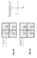
- the scan vectors of one layer are parallel to each other within that layer (see Fig. 2a ) or defined areas (so called chest board patterns) have a fixed angle between the scan vectors in one layer (see Fig. 3a ).
- the scan vectors are either rotated by an angle of for example 90° (see Fig. 2b , 3b ) or by an angle different of 90° or n*90°. (see Fig. 4a, 4b ).
- This using alternating scanner paths for subsequent layers or for certain areas of a pattern, e.g. chest board, within one layer of the article) was done so far to achieve a good quality (optimum part/article density and geometrical accuracy) with respect to an article made by SLM.
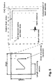
- FIG. 5 A typical SLM track alignment known from the state of the art is shown in Fig. 5 .
- a faster and preferred grain growth perpendicular to the powder plane (x-y plane) is favoured.
- This results in a characteristic microstructure showing elongated grains in the z-direction ( primary grain orientation direction, crystallographic [001] direction).
- one characteristic feature of powder-based or other additive manufacturing technology is the strong anisotropy of material properties (for example Young's modulus, yield strength, tensile strength, low cycle fatigue behaviour, creep) resulting from the known layer-wise build-up process and the local solidification conditions during the SLM powder bed processing.
- material properties for example Young's modulus, yield strength, tensile strength, low cycle fatigue behaviour, creep
- the SLM technique is able to manufacture high performance and complex shaped parts due to its capability to generate very sophisticated designs directly from a powder bed.
- a similar control of the microstructure as described above for cast SX or DS components would be thus highly beneficial for parts and prototypes which are manufactured with the SLM technique or other additive manufacturing laser techniques.
- An additional control and alignment of the Young's modulus would further increase the performance and application potential of such components.
- the present invention discloses a control of secondary crystallographic orientation of grains for metallic components / three-dimensional articles (for example coupons, inserts for components) made of Ni-, Co-, or Fe based superalloys processed by additive manufacturing technology. For this, an appropriate placement of the scanner paths during the article generation is essential.
- the invention is based on the finding that the secondary crystal orientation can be controlled by the scanning and build-up control.
- the component/article manufactured according to the present invention has a controlled secondary crystallographic grain orientation, which leads to a higher lifetime and operation performance of metallic parts and prototypes in comparison with components manufactured according to the state of the art additive manufacturing methods.
- the method according to the invention for manufacturing entirely or partly a three-dimensional metallic article / component comprises the steps of
- the active control of the secondary grain orientation is achieved by placing the scanner paths alternately parallel (in the first layer) and orthogonal (in the next layer) and so on to the direction of the component, where a smallest value of the Young's modulus is desired.
- the method can be used especially for manufacturing small to medium size hot gas parts and prototypes with complex design. Such parts can be found, for example in the first turbine stages of a gas turbine, in a compressor or in combustors. It is an advantage that the method can be used both for new part manufacturing as well as within a reconditioning/repair process.
- said additive manufacturing process is one of selective laser melting (SLM), selective laser sintering (SLS) or electron beam melting (EBM), and a metallic base material of powder form is used.
- SLM selective laser melting
- SLS selective laser sintering
- EBM electron beam melting
- said SLM or SLS or EBM method comprises the steps of:
- the energy beam for example high density energy laser beam, is scanned with such a specific scanning pattern that the secondary crystallographic grain orientation matches with the design intent of the component.
- the grain size distribution of said powder is adjusted to the layer thickness of said powder layer in order to establish a good flowability, which is required for preparing powder layers with regular and uniform thickness.
- the powder grains have a spherical shape.
- an exact grain size distribution of the powder is obtained by sieving and/or winnowing (air separation).
- said powder is provided by means of a powder metallurgical process, specifically one of gas or water atomization, plasma-rotating-electrode process or mechanical milling.
- said metallic base material is a high-temperature Ni-based alloy.
- said metallic base material is a high-temperature Co-based alloy.
- said metallic base material is a high-temperature Fe-based alloy.
- said alloy can contain finely dispersed oxides, specifically one of Y 2 O 3 , AlO 3 , ThO 2 , HfO 2 , ZrO 2 .
- An important aspect of the present invention is the fact that the preferred microstructures do not have to be implemented in the whole volume of the part. Instead, the alignment can be turned on and off in an arbitrary manner for different zones, depending on the local mechanical integrity (MI) requirements. This is an advantage compared to investment casting or E(epitaxial)-LMF, where the control of the microstructure is lost, once epitaxial growth conditions are no longer present and equiaxed grain growth has occurred.
- MI local mechanical integrity
- one characteristic feature of powder-based additive manufacturing technology is the strong anisotropy of material properties resulting from the layer-wise build-up process.
- the material in the "as built" condition has a very fine microstructure (e.g. precipitates and grain size), much finer compared to conventionally cast or wrought superalloys.
- scanning strategy I always a significantly lower Young's modulus was achieved in comparison to the different scanning strategy M. This is true for both of the primary (z-direction) and the secondary orientation (x-y plane) and also for two different testing temperatures (Room Temperature RT and 750°C).
- the method according to the invention for manufacturing a three-dimensional metallic article / component comprises the steps of
- the secondary grain orientation is aligned with the characteristic load conditions of the component, e.g. follows the component cross-section profile.
- the active control of the secondary grain orientation is achieved by placing the scanner paths alternately parallel (in the first layer) and orthogonal (in the next layer) and so on in the following layers to the direction of the component, where a smallest value of the Young's modulus is desired.
- Said additive manufacturing technology is especially selective laser melting (SLM), selective laser sintering (SLS), and electron beam melting (EBM).
- Said powder-based additive manufacturing technology may be used to build up an article, such as a blade or vane of a gas turbine, entirely or partly, e.g. blade crown build up.
- the article could also be an insert or a coupon used for example for repair processes of a whole component.
- the method according to the invention comprises the following steps:
- Fig. 7 shows optical micrographs of a Ni-base superalloy in etched condition and orientation maps derived from electron back-scattered diffraction (EBSD) scans.
- EBSD electron back-scattered diffraction
- the preferred crystal orientation obtained by EBSD represented as pole figures (001) and as inverse pole figures is shown with respect to the building direction z.
- All orientation maps are coloured by using the standard inverse pole figure (IPF) colour key with respect to the building direction z. It can be seen that the grains do not only show a preferred orientation along z-axis, but also within the x-y plane.
- the secondary crystallographic grain orientation corresponds to the applied laser movement (e.g. 45° within x-y plane).
- components for example a gas turbine blade, can be produced, which have optimised mechanical properties in the most heavily loaded areas.
- the directions with smallest values of the Young's modulus are aligned with the load conditions of the blade.
- the active control of the secondary grain orientation is achieved by placing the scanner paths parallel and orthogonal to the direction of the component, where a smallest value of the Young's modulus is desired.
- the angular change of the scanner path direction in the different layers must always be 90° or a multiple of this value (see Fig. 2a, 2b ).
- the invention relates to the finding that the secondary crystallographic orientation is being established by using scan vectors which are perpendicular between each layer or between each certain area (islands) of a layer.
- An important aspect of the present invention is the fact that the preferred microstructures do not have to be implemented in the whole volume of the component. Instead, the alignment can be turned on and off in an arbitrary manner for different zones, depending on the local mechanical integrity (MI) requirements. This is an advantage compared to investment casting or E-LMF, where the control of the microstructure is lost, once epitaxial growth conditions are no longer present and equiaxed grain growth has occurred.
- MI local mechanical integrity
- the grain size distribution of the powder used in this SLM, SLS or EBM processes is adjusted to the layer thickness d to have to a good flowability, which is required for preparing powder layers with regular and uniform thickness d.
- the powder grains of the powder used in this process have a spherical shape.
- the exact grain size distribution of the powder may be obtained by sieving and/or winnowing (air separation).
- the powder may be obtained by gas or water atomization, plasma-rotating-electrode process, mechanical milling and like powder metallurgical processes.
- a suspension may be used instead of powder.
- said high temperature material is a Ni-based alloy
- a plurality of commercially available alloys may be used like Waspaloy®, Hastelloy® X, IN617®, IN718®, IN625®, Mar-M247®, IN100®, IN738®, 1N792®, Mar-M200®, B1900®, RENE 80®, Alloy 713®, Haynes 230®, Haynes 282®, or other derivatives.
- said high temperature material is a Co-based alloy
- a plurality of commercially available alloys may be used like FSX 414®, X-40®, X-45®, MAR-M 509® or MAR-M 302®.
- said high temperature material is a Fe-based alloy
- a plurality of commercially available alloys may be used like A 286®, Alloy 800 H®, N 155®, S 590®, Alloy 802®, Incoloy MA 956®, Incoloy MA 957@ or PM 2000®.
- these alloys may contain fine dispersed oxides such as Y2O3, AlO3, Th02, Hf02, Zr02.
- the component manufactured with the method according to the invention is a blade or a vane for a turbo machine.
- the blade/vane comprises an airfoil with a profile.
- the alignment of the secondary grain orientation is matched with the airfoil profile and the alignment of the secondary grain orientation is gradually and continuously adapted to the shape of the airfoil. This will lead to very good mechanical and fatigue properties.
Landscapes
- Engineering & Computer Science (AREA)
- Mechanical Engineering (AREA)
- Chemical & Material Sciences (AREA)
- Materials Engineering (AREA)
- Manufacturing & Machinery (AREA)
- Physics & Mathematics (AREA)
- Optics & Photonics (AREA)
- Automation & Control Theory (AREA)
- Plasma & Fusion (AREA)
- General Engineering & Computer Science (AREA)
- Composite Materials (AREA)
- Powder Metallurgy (AREA)
- Turbine Rotor Nozzle Sealing (AREA)
- Welding Or Cutting Using Electron Beams (AREA)
- Laser Beam Processing (AREA)
- Architecture (AREA)
Abstract
a) successively building up said article /component (11) from a metallic base material (12) by means of an additive manufacturing process by scanning with an energy beam (14), thereby
b) establishing a controlled grain orientation in primary and in secondary direction of the article /component (11),
c) wherein the secondary grain orientation is realized by applying a specific scanning pattern of the energy beam (14), which is aligned to the cross section profile of said article /component (14), or with characteristic load conditions of the article/component (11).

Description
- The present invention relates to the technology of high-temperature resistant components, especially hot gas path components for gas turbines. It refers to a method for manufacturing a metallic component / three-dimensional article by additive manufacturing technologies, such as selective laser melting (SLM), selective laser sintering (SLS) or electron beam melting (EBM).
- Additive manufacturing has become a more and more attractive solution for the manufacturing of metallic functional prototypes and components. It is known that SLM, SLS and EBM methods use powder material as base material. The component or article is generated directly from a powder bed. Other additive manufacturing methods, such laser metal forming (LMF), laser engineered net shape (LENS) or direct metal deposition (DMD) locally fuse material onto an existing part. This newly generated material may be deposited either as wire or as powder, where the powder deposition device is moved along predefined path with either a robot or a CNC machine.
-
Fig. 1 shows abasic SLM arrangement 10, known from the prior art, wherein a three-dimensional article (component) 11 is manufactured by successive addition ofpowder layers 12 of a predetermined layer thickness d, area and contour, which are then melted by means of a scannedlaser beam 14 from alaser device 13 and controlled by acontrol unit 15. - Usually, the scan vectors of one layer are parallel to each other within that layer (see
Fig. 2a ) or defined areas (so called chest board patterns) have a fixed angle between the scan vectors in one layer (seeFig. 3a ). Between subsequent layers (that means between layer n and layer n+1; and between layer n+1 and layer n+2 and so on) the scan vectors are either rotated by an angle of for example 90° (seeFig. 2b ,3b ) or by an angle different of 90° or n*90°. (seeFig. 4a, 4b ). This (using alternating scanner paths for subsequent layers or for certain areas of a pattern, e.g. chest board, within one layer of the article) was done so far to achieve a good quality (optimum part/article density and geometrical accuracy) with respect to an article made by SLM. - A typical SLM track alignment known from the state of the art is shown in
Fig. 5 . - Due to the typical temperature profile in the melt pool and the resulting thermal gradients in the vicinity of the melt pool, a faster and preferred grain growth perpendicular to the powder plane (x-y plane) is favoured. This results in a characteristic microstructure showing elongated grains in the z-direction (= primary grain orientation direction, crystallographic [001] direction). This direction is perpendicular to the x-y plane. Therefore, a first specimen extending in z-direction (see
Fig. 1 ) shows properties different from a second specimen extending in the x-y plane (= secondary grain orientation direction, secondary crystallographic direction), for example the Young's modulus along the z-direction is generally different than the Young's modulus in the powder plane (x-y plane). - Therefore, one characteristic feature of powder-based or other additive manufacturing technology is the strong anisotropy of material properties (for example Young's modulus, yield strength, tensile strength, low cycle fatigue behaviour, creep) resulting from the known layer-wise build-up process and the local solidification conditions during the SLM powder bed processing.
- Such anisotropy of material properties could be a disadvantage in several applications. Therefore, the applicant has already filed two so far unpublished patent applications, which disclose that the anisotropic material behaviour of components manufactured by additive laser manufacturing techniques can be reduced by an appropriate "post-built" heat treatment, resulting in more isotropic material properties.
- During the last 3 decades directionally solidified (DS) and single-crystal (SX) turbine components were developed, which are produced by investment casting and where low values of for example the Young's modulus in primary and secondary grain orientation (normal to the primary growth direction) are aligned with thermo-mechanical load conditions. Such an alignment is here provided by application of seed crystals and grain selectors and has resulted in a significant increase of the components performance and lifetime.
- However, so far such techniques to control the primary as well as the secondary crystallographic orientation are not known for parts/components produced by SLM.
- It has also become possible to control the microstructure of deposits formed on single-crystal (SX) substrates with generative laser processes, a technique called epitaxial laser metal forming (E-LMF). These methods can produce parts, which have either a preferred grain orientation (DS) or an absence of grain boundaries (SX).
- With increasing design complexity of future hot gas path components, the economic manufacturing of such SX or DS parts/components by casting will become more and more problematic, as the casting yield for thin- or double walled components is expected to drop. Moreover, epitaxial laser metal forming can be only applied to parts, where the base material has already a single crystal orientation.
- The SLM technique is able to manufacture high performance and complex shaped parts due to its capability to generate very sophisticated designs directly from a powder bed. A similar control of the microstructure as described above for cast SX or DS components would be thus highly beneficial for parts and prototypes which are manufactured with the SLM technique or other additive manufacturing laser techniques. An additional control and alignment of the Young's modulus would further increase the performance and application potential of such components.
- It is an object of the present invention to disclose a method for entirely or partly manufacturing a metallic component / a three-dimensional article by additive manufacturing methods with improved properties, where the anisotropic properties can either be used in a favourable manner, or where anisotropy can be reduced or avoided, depending on the design intent for the component. It is also an object of the present invention to disclose an appropriate method for realizing an alignment of the anisotropic properties of the article with the local thermo-mechanical load conditions.
- This and other objects are obtained by a method according to
claim 1. - The present invention discloses a control of secondary crystallographic orientation of grains for metallic components / three-dimensional articles (for example coupons, inserts for components) made of Ni-, Co-, or Fe based superalloys processed by additive manufacturing technology. For this, an appropriate placement of the scanner paths during the article generation is essential.
- It is beneficial to control the microstructure of the generated material and to make use of this characteristic material anisotropy.
- The invention is based on the finding that the secondary crystal orientation can be controlled by the scanning and build-up control.
- The component/article manufactured according to the present invention has a controlled secondary crystallographic grain orientation, which leads to a higher lifetime and operation performance of metallic parts and prototypes in comparison with components manufactured according to the state of the art additive manufacturing methods.
- The method according to the invention for manufacturing entirely or partly a three-dimensional metallic article / component comprises the steps of
- a) successively building up said article / component from a metallic base material by means of an additive manufacturing process by scanning with an energy beam, thereby
- b) establishing a controlled grain orientation in primary and in secondary direction of the article / component,
- c) wherein the secondary grain orientation is realized by applying a specific scanning pattern of the energy beam which is aligned to the cross section profile of said article / component or with the local load conditions of the article/component.
- In a preferred embodiment of the method the active control of the secondary grain orientation is achieved by placing the scanner paths alternately parallel (in the first layer) and orthogonal (in the next layer) and so on to the direction of the component, where a smallest value of the Young's modulus is desired.
- The method can be used especially for manufacturing small to medium size hot gas parts and prototypes with complex design. Such parts can be found, for example in the first turbine stages of a gas turbine, in a compressor or in combustors. It is an advantage that the method can be used both for new part manufacturing as well as within a reconditioning/repair process.
- According to an embodiment of the invention said additive manufacturing process is one of selective laser melting (SLM), selective laser sintering (SLS) or electron beam melting (EBM), and a metallic base material of powder form is used.
- Specifically, said SLM or SLS or EBM method comprises the steps of:
- a) generating a three-dimensional model of said article followed by a slicing process to calculate the cross sections;
- b) passing said calculated cross sections to a machine control unit (15) afterwards;
- c) providing a powder of said base material, which is needed for the process;
- d) preparing a powder layer (12) with a regular and uniform thickness on a substrate plate or on a previously processed powder layer;
- e) performing melting by scanning with an energy beam (14) corresponding to a cross section of said articles according to the three-dimensional model stored in the control unit (15);
- f) lowering the upper surface of the previously formed cross section by one layer thickness (d);
- g) repeating said steps from d) to f) until reaching the last cross section according to the three-dimensional model; and
- h) optionally heat treating said three-dimensional article (11), wherein in steps e) the energy beam is scanned in such a way that
- scan vectors are either perpendicular between subsequent layers or between each certain areas (islands) of a layer thereby establishing a specific desired secondary crystallographic grain orientation or
- scan vectors have random angles between subsequent layers or between each certain areas (islands) of a layer thereby not establishing a specific secondary crystallographic grain orientation.
- The energy beam, for example high density energy laser beam, is scanned with such a specific scanning pattern that the secondary crystallographic grain orientation matches with the design intent of the component.
- More specifically, the grain size distribution of said powder is adjusted to the layer thickness of said powder layer in order to establish a good flowability, which is required for preparing powder layers with regular and uniform thickness. According to a further embodiment of the invention the powder grains have a spherical shape.
- According to just another embodiment of the invention an exact grain size distribution of the powder is obtained by sieving and/or winnowing (air separation).
- According to another embodiment of the invention said powder is provided by means of a powder metallurgical process, specifically one of gas or water atomization, plasma-rotating-electrode process or mechanical milling.
- According to another embodiment of the invention said metallic base material is a high-temperature Ni-based alloy.
- According to another embodiment of the invention said metallic base material is a high-temperature Co-based alloy.
- According to just another embodiment of the invention said metallic base material is a high-temperature Fe-based alloy.
- Specifically, said alloy can contain finely dispersed oxides, specifically one of Y2O3, AlO3, ThO2, HfO2, ZrO2.
- An important aspect of the present invention is the fact that the preferred microstructures do not have to be implemented in the whole volume of the part. Instead, the alignment can be turned on and off in an arbitrary manner for different zones, depending on the local mechanical integrity (MI) requirements. This is an advantage compared to investment casting or E(epitaxial)-LMF, where the control of the microstructure is lost, once epitaxial growth conditions are no longer present and equiaxed grain growth has occurred.
- The present invention is now to be explained more closely by means of different embodiments and with reference to the attached drawings.
- Fig. 1
- shows a basic arrangement for SLM manufacturing according to the state of the art, which may be used in the present invention;
- Fig. 2a, 2b
- show a first scanning strategy (with alternating scan vectors with 90° angle between adjacent layers) for SLM manufacturing;
- Fig. 3a, 3b
- show a second scanning strategy (chest board strategy) for SLM manufacturing;
- Fig. 4a to 4c
- show two additional scanning strategies (with alternating scan vectors with 63° angle between adjacent layers or with random angles) for SLM manufacturing;
- Fig. 5
- shows a typical SLM track alignment known from the state of the art;
- Fig. 6
- shows values of Young's modulus at Room Temperature and at 750°C as testing temperature for two different scanning strategies for specimen made of Hastelloy® X measured in the "as built" condition and
- Fig. 7
- shows optical micrographs of a Ni-base superalloy in etched condition and orientation maps derived from electron back-scattered diffraction (EBSD) scans.
- As described above in the prior art, one characteristic feature of powder-based additive manufacturing technology is the strong anisotropy of material properties resulting from the layer-wise build-up process.
- It has turned out that the mechanical properties along the z-direction are different to ones in the x-y plane, which is the powder plane. The Young's modulus along the z-direction (built direction) is generally lower than the Young's modulus in the x-y plane. This is shown in
Fig. 6 for specimens made of Hastalloy® X by additive manufacturing with two different scanning strategies, that means two different scanning patterns, and which were tested at room temperature RT and at a temperature of 750°C. The Young's modulus was measured in the "as built" condition. Due to powder-based article production and the inherent high cooling rates of the energy beam-material interaction in these processes, the material is very homogeneous with respect to chemical composition and principally free of segregations. In addition, the material in the "as built" condition has a very fine microstructure (e.g. precipitates and grain size), much finer compared to conventionally cast or wrought superalloys. With scanning strategy I always a significantly lower Young's modulus was achieved in comparison to the different scanning strategy M. This is true for both of the primary (z-direction) and the secondary orientation (x-y plane) and also for two different testing temperatures (Room Temperature RT and 750°C). - The observation about columnar grain growth in the [001] direction is well known. However, a similar directional dependency also exists in the x-y plane. It was found, that with certain process set-ups it is possible to control [001] growth within the secondary plane (scanner movement plane).
- The method according to the invention for manufacturing a three-dimensional metallic article / component comprises the steps of
- a) successively building up said article /component from a metallic base material by means of an additive manufacturing process by scanning with an energy beam, thereby
- b) establishing a controlled grain orientation in primary and in secondary direction of the article /component,
- c) wherein the secondary grain orientation is realized by applying a specific scanning pattern of the energy beam which is aligned to the cross section profile of said article /component or with the local load conditions of the article/component.
- It is essentially for the present invention that the secondary grain orientation is aligned with the characteristic load conditions of the component, e.g. follows the component cross-section profile.
- In one embodiment of the disclosed method the active control of the secondary grain orientation is achieved by placing the scanner paths alternately parallel (in the first layer) and orthogonal (in the next layer) and so on in the following layers to the direction of the component, where a smallest value of the Young's modulus is desired.
- Said additive manufacturing technology is especially selective laser melting (SLM), selective laser sintering (SLS), and electron beam melting (EBM). Said powder-based additive manufacturing technology may be used to build up an article, such as a blade or vane of a gas turbine, entirely or partly, e.g. blade crown build up. The article could also be an insert or a coupon used for example for repair processes of a whole component.
- When selective laser melting SLM, selective laser sintering SLS or electron beam melting EBM is used as the additive manufacturing technology the method according to the invention comprises the following steps:
- a) generating a three-dimensional model of said article followed by a slicing process to calculate the cross sections;
- b) passing said calculated cross sections to a machine control unit (15) afterwards;
- c) providing a powder of said base material, for example of Ni based superalloy, which is needed for the process;
- d) preparing a powder layer (12) with a regular and uniform thickness on a substrate plate or on a previously processed powder layer;
- e) performing melting by scanning with an energy beam (14) corresponding to a cross section of said articles according to the three-dimensional model stored in the control unit (15);
- f) lowering the upper surface of the previously formed cross section by one layer thickness (d);
- g) repeating said steps from d) to f) until reaching the last cross section according to the three-dimensional model; and
- h) optionally heat treating said three-dimensional article (11), wherein in step e) the energy beam is scanned in such a way that
- scan vectors are either perpendicular between each subsequent layer or between each certain areas (islands) of a layer thereby establishing a specific desired secondary crystallographic grain orientation or
- scan vectors have random angles between each subsequent layer or between each certain areas (islands) of a layer thereby not establishing a specific secondary crystallographic grain orientation.
-
Fig. 7 shows optical micrographs of a Ni-base superalloy in etched condition and orientation maps derived from electron back-scattered diffraction (EBSD) scans. In addition, the preferred crystal orientation obtained by EBSD, represented as pole figures (001) and as inverse pole figures is shown with respect to the building direction z. All orientation maps are coloured by using the standard inverse pole figure (IPF) colour key with respect to the building direction z. It can be seen that the grains do not only show a preferred orientation along z-axis, but also within the x-y plane. Furthermore, the secondary crystallographic grain orientation corresponds to the applied laser movement (e.g. 45° within x-y plane). - With this tailored SLM build-up method, components, for example a gas turbine blade, can be produced, which have optimised mechanical properties in the most heavily loaded areas. For this purpose, the directions with smallest values of the Young's modulus are aligned with the load conditions of the blade.
- It is essential that not only a primary, but also the secondary crystallographic orientation of the grains is favourably matched with the design intent of the component, resulting in extended service lifetime.
- The active control of the secondary grain orientation is achieved by placing the scanner paths parallel and orthogonal to the direction of the component, where a smallest value of the Young's modulus is desired. The angular change of the scanner path direction in the different layers must always be 90° or a multiple of this value (see
Fig. 2a, 2b ). - The invention relates to the finding that the secondary crystallographic orientation is being established by using scan vectors which are perpendicular between each layer or between each certain area (islands) of a layer.
- It is also possible to get rid of the preferred secondary orientation (achieve a non-pronounced secondary orientation) by using scan vectors, which are parallel within each island of each layer and rotated by for example an angle of 63° in each subsequent layer (see
Fig. 4a, 4b ) or use random angles (seeFig. 4c, 4d ) to vary the scan direction within each island and each layer. An optimal scan pattern for non-pronounced secondary orientation is 63°/xx°. - An important aspect of the present invention is the fact that the preferred microstructures do not have to be implemented in the whole volume of the component. Instead, the alignment can be turned on and off in an arbitrary manner for different zones, depending on the local mechanical integrity (MI) requirements. This is an advantage compared to investment casting or E-LMF, where the control of the microstructure is lost, once epitaxial growth conditions are no longer present and equiaxed grain growth has occurred.
- Preferably, the grain size distribution of the powder used in this SLM, SLS or EBM processes is adjusted to the layer thickness d to have to a good flowability, which is required for preparing powder layers with regular and uniform thickness d.
- Preferably, the powder grains of the powder used in this process have a spherical shape. The exact grain size distribution of the powder may be obtained by sieving and/or winnowing (air separation). Furthermore, the powder may be obtained by gas or water atomization, plasma-rotating-electrode process, mechanical milling and like powder metallurgical processes.
- In other cases, a suspension may be used instead of powder.
- When said high temperature material is a Ni-based alloy, a plurality of commercially available alloys may be used like Waspaloy®, Hastelloy® X, IN617®, IN718®, IN625®, Mar-M247®, IN100®, IN738®, 1N792®, Mar-M200®, B1900®,
RENE 80®, Alloy 713®, Haynes 230®, Haynes 282®, or other derivatives. - When said high temperature material is a Co-based alloy, a plurality of commercially available alloys may be used like FSX 414®, X-40®, X-45®, MAR-M 509® or MAR-M 302®.
- When said high temperature material is a Fe-based alloy, a plurality of commercially available alloys may be used like A 286®, Alloy 800 H®, N 155®, S 590®, Alloy 802®, Incoloy MA 956®, Incoloy MA 957@ or PM 2000®.
- Especially, these alloys may contain fine dispersed oxides such as Y2O3, AlO3, Th02, Hf02, Zr02.
- In one preferred embodiment the component manufactured with the method according to the invention is a blade or a vane for a turbo machine. The blade/vane comprises an airfoil with a profile. The alignment of the secondary grain orientation is matched with the airfoil profile and the alignment of the secondary grain orientation is gradually and continuously adapted to the shape of the airfoil. This will lead to very good mechanical and fatigue properties.
- Mechanical testing and microstructural assessment have shown that specimens built by the SLM process or by other additive manufacturing process have a strong anisotropic behaviour. By scanning and controlling the energy beam in such a way that the secondary crystallographic grain orientation matches with the design intent of the component (alignment with characteristic load conditions), components can be produced, which have optimised mechanical properties in the most heavily loaded areas. For this purpose, the directions with the smallest values of the Young's modulus are aligned with the load conditions of the component.
-
- 10
- SLM arrangement
- 11
- article (3D), component
- 12
- powder layer
- 13
- laser device
- 14
- laser beam
- 15
- control unit
- d
- layer thickness (powder layer)
Claims (15)
- Method for manufacturing a three-dimensional metallic article /component (11) entirely or partly, comprising the steps ofa) successively building up said article / component (11) from a metallic base material (12) by means of an additive manufacturing process by scanning with an energy beam (14), therebyb) establishing a controlled grain orientation in primary and in secondary direction of the article/component (11),c) wherein the controlled secondary grain orientation is realized by applying a specific scanning pattern of the energy beam (14), which is aligned to the cross section profile of said article / component (14) or to the local load conditions for said article / component (11).
- Method according to claim 1, characterized in that the control of the secondary grain orientation is achieved by placing the scanner paths alternately parallel and orthogonal in subsequent layers to the direction of the component (11), where a smallest value of the Young's modulus is desired.
- Method according to claim 1, characterized in that in order to achieve a non-pronounced secondary grain orientation the scanner paths are rotated by random angles in subsequent layers.
- Method according to claim 1, characterized in that in order to achieve a non-pronounced secondary grain orientation the scan vectors are parallel within each island of each layer and rotated by 63° in each subsequent layer.
- Method according to one of claims 1 to 4, characterized in that said additive manufacturing process is one of selective laser melting (SLM), selective laser sintering (SLS) or electron beam melting (EBM), that a metallic base material of powder form is used and said method comprises the steps of:a) generating a three-dimensional model of said article followed by a slicing process to calculate the cross sections;b) passing said calculated cross sections to a machine control unit (15) afterwards;c) providing a powder of said base material, which is needed for the process;d) preparing a powder layer (12) with a regular and uniform thickness on a substrate plate or on a previously processed powder layer;e) performing melting by scanning with a energy beam (14) an area corresponding to a cross section of said articles according to the three-dimensional model stored in the control unit (15);f) lowering the upper surface of the previously formed cross section by one layer thickness (d);g) repeating said steps from c) to f) until reaching the last cross section according to the three-dimensional model; andh) optionally heat treating said three-dimensional article (11), wherein in steps e) the energy beam (14) is scanned in such a way that- scan vectors are either perpendicular between each subsequent layer or between each certain areas (islands) of a layer thereby establishing a specific desired secondary crystallographic grain orientation or- scan vectors have random angles between each subsequent layer or between each certain areas (islands) of a layer thereby not establishing a specific secondary crystallographic grain orientation.
- Method according to claim 5, characterized in that the grain size distribution of said powder is adjusted to the layer thickness (d) of said powder layer (12) in order to establish a good flowability, which is required for preparing powder layers (12) with regular and uniform thickness (d).
- Method according to claim 5, characterized in that the powder grains have a spherical shape and that an exact grain size distribution of the powder is obtained by sieving and/or winnowing (air separation).
- Method according to claim 5, characterized in that said powder is provided by means of a powder metallurgical process, specifically one of gas or water atomization, plasma-rotating-electrode process or mechanical milling.
- Method according to claim 5, characterized in that said additive manufacturing process uses a suspension instead of powder.
- Method according to one of the claims 1-9, characterized in that said metallic base material is one of a high-temperature Ni-based alloy, Co-based alloy, Fe-based alloy or combinations thereof.
- Method according to claims 10, characterized in that said alloy contain finely dispersed oxides, specifically one of Y2O3, AlO3, ThO2, HfO2, ZrO2.
- Method according to one of claims 1, 2, 5, characterized in that the preferential alignment of the secondary grain orientation is applied only in designated sub-volumes.
- Component (11) manufactured by a method according to one of claims 1-12, characterized in that the component (11) is used in the compressor, combustor or turbine section of a gas turbine, preferably as a blade, a vane or a heat shield.
- Component (11) according to claim 13, wherein the component comprises an airfoil with a profile, characterized in that the alignment of the secondary grain orientation is matched with the profile of the airfoil and that it is gradually and continuously adapted to the shape of the airfoil.
- Component (11) according to claim 13, wherein the alignment of the secondary grain orientation is matched with the local load conditions of the part.
Priority Applications (9)
| Application Number | Priority Date | Filing Date | Title |
|---|---|---|---|
| EP12008074.2A EP2737965A1 (en) | 2012-12-01 | 2012-12-01 | Method for manufacturing a metallic component by additive laser manufacturing |
| RU2013151901/02A RU2574536C2 (en) | 2012-12-01 | 2013-11-21 | Production of metal component by additive laser process |
| CA2833890A CA2833890C (en) | 2012-12-01 | 2013-11-21 | Method for manufacturing a metallic component by additive laser manufacturing |
| US14/091,780 US20140154088A1 (en) | 2012-12-01 | 2013-11-27 | Method for manufacturing a metallic component by additive laser manufacturing |
| AU2013263783A AU2013263783B2 (en) | 2012-12-01 | 2013-11-28 | Method for manufacturing a metallic component by additive laser manufacturing |
| KR1020130146170A KR20140071907A (en) | 2012-12-01 | 2013-11-28 | Method for manufacturing a metallic component by additive laser manufacturing |
| CN201310621038.6A CN103846437B (en) | 2012-12-01 | 2013-11-29 | Method of manufacturing a metal part by additive laser manufacturing |
| JP2013249275A JP5933512B2 (en) | 2012-12-01 | 2013-12-02 | Method of manufacturing metal parts by laser additive manufacturing method |
| KR1020160102513A KR20160100883A (en) | 2012-12-01 | 2016-08-11 | Method for manufacturing a metallic component by additive laser manufacturing |
Applications Claiming Priority (1)
| Application Number | Priority Date | Filing Date | Title |
|---|---|---|---|
| EP12008074.2A EP2737965A1 (en) | 2012-12-01 | 2012-12-01 | Method for manufacturing a metallic component by additive laser manufacturing |
Publications (1)
| Publication Number | Publication Date |
|---|---|
| EP2737965A1 true EP2737965A1 (en) | 2014-06-04 |
Family
ID=47290562
Family Applications (1)
| Application Number | Title | Priority Date | Filing Date |
|---|---|---|---|
| EP12008074.2A Withdrawn EP2737965A1 (en) | 2012-12-01 | 2012-12-01 | Method for manufacturing a metallic component by additive laser manufacturing |
Country Status (7)
| Country | Link |
|---|---|
| US (1) | US20140154088A1 (en) |
| EP (1) | EP2737965A1 (en) |
| JP (1) | JP5933512B2 (en) |
| KR (2) | KR20140071907A (en) |
| CN (1) | CN103846437B (en) |
| AU (1) | AU2013263783B2 (en) |
| CA (1) | CA2833890C (en) |
Cited By (14)
| Publication number | Priority date | Publication date | Assignee | Title |
|---|---|---|---|---|
| CN104475728A (en) * | 2014-12-13 | 2015-04-01 | 广东汉唐量子光电科技有限公司 | Control method and controller for 3D (three-dimension) printing and scanning |
| EP3025809A1 (en) | 2014-11-28 | 2016-06-01 | Alstom Technology Ltd | Method for manufacturing a component using an additive manufacturing process |
| EP3034203A1 (en) | 2014-12-19 | 2016-06-22 | Alstom Technology Ltd | Method for producing a metallic component |
| WO2016128388A1 (en) * | 2015-02-11 | 2016-08-18 | Ksb Aktiengesellschaft | Flow-conducting component |
| WO2016156020A1 (en) * | 2015-03-27 | 2016-10-06 | Arcam Ab | Improved method for additive manufacturing |
| CN107877852A (en) * | 2016-09-28 | 2018-04-06 | 上海普利生机电科技有限公司 | Light-cured type 3 D-printing method |
| EP3305444A1 (en) | 2016-10-08 | 2018-04-11 | Ansaldo Energia IP UK Limited | Method for manufacturing a mechanical component |
| EP3248715A4 (en) * | 2016-03-09 | 2018-04-25 | Technology Research Association for Future Additive Manufacturing | 3d additive manufacturing system, 3d additive manufacturing method, additive manufacturing control device, and control method and control program for additive manufacturing control device |
| EP3441162A1 (en) * | 2017-08-11 | 2019-02-13 | Siemens Aktiengesellschaft | Method of additively manufacturing a structure on a pre-existing component out of the powder bed |
| EP3459654A1 (en) * | 2017-09-22 | 2019-03-27 | SLM Solutions Group AG | Method and apparatus for producing a single-crystalline workpiece |
| EP3552802A1 (en) * | 2018-04-13 | 2019-10-16 | CL Schutzrechtsverwaltungs GmbH | Method for operating at least one apparatus for additively manufacturing three-dimensional objects |
| CN111097907A (en) * | 2019-12-28 | 2020-05-05 | 同济大学 | Orientation method of iron-based material |
| WO2021234368A1 (en) | 2020-05-21 | 2021-11-25 | Renishaw Plc | Additive manufacturing methods and apparatus for forming objects from a nickel-based superalloy in a layer-by-layer manner |
| US11752552B2 (en) | 2017-10-27 | 2023-09-12 | Siemens Energy Global GmbH & Co. KG | Method for modifying components using additive manufacturing |
Families Citing this family (93)
| Publication number | Priority date | Publication date | Assignee | Title |
|---|---|---|---|---|
| EP2772329A1 (en) * | 2013-02-28 | 2014-09-03 | Alstom Technology Ltd | Method for manufacturing a hybrid component |
| ES2725889T3 (en) * | 2013-06-10 | 2019-09-30 | Renishaw Plc | Apparatus and method of selective solidification by laser |
| GB201310398D0 (en) | 2013-06-11 | 2013-07-24 | Renishaw Plc | Additive manufacturing apparatus and method |
| EP3096920A4 (en) * | 2014-01-24 | 2017-03-01 | United Technologies Corporation | Additive repair for combustor liner panels |
| US9896944B2 (en) * | 2014-04-18 | 2018-02-20 | Siemens Energy, Inc. | Forming a secondary structure directly onto a turbine blade |
| GB2546016B (en) | 2014-06-20 | 2018-11-28 | Velo3D Inc | Apparatuses, systems and methods for three-dimensional printing |
| JP6470135B2 (en) * | 2014-07-14 | 2019-02-13 | ユナイテッド テクノロジーズ コーポレイションUnited Technologies Corporation | Additional manufactured surface finish |
| ES2856399T3 (en) | 2014-08-20 | 2021-09-27 | Etxetar Sa | Method and system for additive manufacturing using a light beam |
| CN104148636B (en) * | 2014-08-29 | 2017-10-31 | 中国科学院重庆绿色智能技术研究院 | A scanning path generation method for controlling thermal deformation of metal parts in additive manufacturing |
| JP2016053198A (en) * | 2014-09-04 | 2016-04-14 | 株式会社コイワイ | Metal molded product and metal powder for metal molded product |
| GB201420717D0 (en) | 2014-11-21 | 2015-01-07 | Renishaw Plc | Additive manufacturing apparatus and methods |
| US11458539B2 (en) * | 2014-11-24 | 2022-10-04 | Additive Industries B.V. | Apparatus for producing an object by means of additive manufacturing |
| DE102015202347A1 (en) * | 2015-02-10 | 2016-08-11 | Trumpf Laser- Und Systemtechnik Gmbh | Irradiation device, processing machine and method for producing a layer of a three-dimensional component |
| US10507638B2 (en) * | 2015-03-17 | 2019-12-17 | Elementum 3D, Inc. | Reactive additive manufacturing |
| GB201505458D0 (en) * | 2015-03-30 | 2015-05-13 | Renishaw Plc | Additive manufacturing apparatus and methods |
| JP6030186B1 (en) | 2015-05-13 | 2016-11-24 | 株式会社ダイヘン | Copper alloy powder, manufacturing method of layered object, and layered object |
| CN105108142A (en) * | 2015-06-18 | 2015-12-02 | 航星利华(北京)科技有限公司 | Method for manufacturing monocrystalline and directional solidified part through laser 3D printer |
| CN105252000B (en) * | 2015-10-08 | 2017-09-19 | 湖南顶立科技有限公司 | A kind of metal dust increasing material manufacturing method under super-pressure inert gas shielding |
| EP3156164A1 (en) * | 2015-10-14 | 2017-04-19 | Siemens Aktiengesellschaft | Method of producing a workpiece using generative manufacturing ; corresponding workpiece |
| US11691341B2 (en) | 2015-10-30 | 2023-07-04 | Seurat Technologies, Inc. | Part manipulation using printed manipulation points |
| JP2018535121A (en) | 2015-11-06 | 2018-11-29 | ヴェロ・スリー・ディー・インコーポレイテッド | Proficient 3D printing |
| US10207454B2 (en) | 2015-12-10 | 2019-02-19 | Velo3D, Inc. | Systems for three-dimensional printing |
| WO2017132664A1 (en) | 2016-01-28 | 2017-08-03 | Seurat Technologies, Inc. | Additive manufacturing, spatial heat treating system and method |
| EP3995277A1 (en) | 2016-01-29 | 2022-05-11 | Seurat Technologies, Inc. | System for additive manufacturing |
| CN105537590A (en) * | 2016-02-01 | 2016-05-04 | 合肥中加激光技术有限公司 | Method for reducing hot stack influences of metal SLM three-dimensional printing |
| US10610931B2 (en) | 2016-02-16 | 2020-04-07 | Board Of Regents, The University Of Texas System | Method and system for producing functionally graded structures in powder bed fusion processing |
| US20170239891A1 (en) | 2016-02-18 | 2017-08-24 | Velo3D, Inc. | Accurate three-dimensional printing |
| DE102016203785A1 (en) | 2016-03-08 | 2017-09-14 | MTU Aero Engines AG | Method for producing a blade for a turbomachine |
| JP6767699B2 (en) * | 2016-03-23 | 2020-10-14 | 国立大学法人大阪大学 | Method for manufacturing a structure containing a β-type titanium alloy |
| WO2017180116A1 (en) * | 2016-04-13 | 2017-10-19 | Gkn Aerospace North America Inc. | System and method of additive manufacturing |
| WO2018005439A1 (en) | 2016-06-29 | 2018-01-04 | Velo3D, Inc. | Three-dimensional printing and three-dimensional printers |
| US11691343B2 (en) | 2016-06-29 | 2023-07-04 | Velo3D, Inc. | Three-dimensional printing and three-dimensional printers |
| GB201701702D0 (en) * | 2017-02-02 | 2017-03-22 | Renishaw Plc | Methods and system involving additive manufacturing and additively-manufactured article |
| US20190184496A1 (en) * | 2016-08-30 | 2019-06-20 | Weir Group Ip Limited | Forming a rotary part |
| US11219976B2 (en) * | 2016-09-29 | 2022-01-11 | Gkn Aerospace Newington Llc | Manufacturing method for cylindrical parts |
| US20180095450A1 (en) | 2016-09-30 | 2018-04-05 | Velo3D, Inc. | Three-dimensional objects and their formation |
| AT519177B1 (en) * | 2016-10-06 | 2019-04-15 | Trotec Laser Gmbh | Method for engraving, marking and / or inscribing a workpiece with |
| WO2018080440A1 (en) * | 2016-10-25 | 2018-05-03 | Hewlett Packard Development Company, L.P. | Build tray model assignment and fabricated part sorting |
| WO2018079304A1 (en) | 2016-10-25 | 2018-05-03 | 株式会社ダイヘン | Copper alloy powder, laminate molding production method, and laminate molding |
| US10661341B2 (en) | 2016-11-07 | 2020-05-26 | Velo3D, Inc. | Gas flow in three-dimensional printing |
| US20180186080A1 (en) | 2017-01-05 | 2018-07-05 | Velo3D, Inc. | Optics in three-dimensional printing |
| GB201700170D0 (en) * | 2017-01-06 | 2017-02-22 | Rolls Royce Plc | Manufacturing method and apparatus |
| US10549345B2 (en) | 2017-01-10 | 2020-02-04 | General Electric Company | Control system of additive manufacturing systems for controlling movement of sintering devices and related program products |
| US10920595B2 (en) | 2017-01-13 | 2021-02-16 | General Electric Company | Turbine component having multiple controlled metallic grain orientations, apparatus and manufacturing method thereof |
| US11187105B2 (en) * | 2017-02-09 | 2021-11-30 | General Electric Company | Apparatus with thermal break |
| WO2018160807A1 (en) | 2017-03-02 | 2018-09-07 | Velo3D, Inc. | Three-dimensional printing of three dimensional objects |
| US10695865B2 (en) | 2017-03-03 | 2020-06-30 | General Electric Company | Systems and methods for fabricating a component with at least one laser device |
| US10668534B2 (en) * | 2017-03-06 | 2020-06-02 | General Electric Company | Leg elimination strategy for hatch pattern |
| US10828700B2 (en) * | 2017-03-06 | 2020-11-10 | General Electric Company | Triangle hatch pattern for additive manufacturing |
| US10449696B2 (en) | 2017-03-28 | 2019-10-22 | Velo3D, Inc. | Material manipulation in three-dimensional printing |
| US10906132B2 (en) | 2017-03-31 | 2021-02-02 | General Electric Company | Scan strategies for efficient utilization of laser arrays in direct metal laser melting (DMLM) |
| US10898968B2 (en) * | 2017-04-28 | 2021-01-26 | Divergent Technologies, Inc. | Scatter reduction in additive manufacturing |
| JP7136811B2 (en) | 2017-05-11 | 2022-09-13 | シューラット テクノロジーズ,インク. | Switchyard Beam Routing of Patterned Light for Additive Manufacturing |
| WO2018209226A1 (en) | 2017-05-11 | 2018-11-15 | Seurat Technologies, Inc. | Solid state routing of patterned light for additive manufacturing optimization |
| EP3643475A4 (en) * | 2017-06-20 | 2021-07-07 | Toray Engineering Co., Ltd. | Method for predicting strength of structure , method for forming structure, method for assisting layer formation of structure, and program |
| US10758976B2 (en) * | 2017-06-21 | 2020-09-01 | General Electric Company | Systems and methods for powder pretreatment in additive manufacturing |
| JP6349449B1 (en) * | 2017-09-19 | 2018-06-27 | 三菱日立パワーシステムズ株式会社 | Turbine blade manufacturing method and turbine blade |
| EP3482853A1 (en) * | 2017-11-13 | 2019-05-15 | Renishaw PLC | Additive manufacturing apparatus and methods |
| EP3461575A1 (en) * | 2017-09-29 | 2019-04-03 | Renishaw PLC | Additive manufacturing apparatus and methods |
| WO2019111827A1 (en) * | 2017-12-06 | 2019-06-13 | 日立金属株式会社 | Method for manufacturing additive manufactured metal object, and additive manufactured metal object |
| US10272525B1 (en) | 2017-12-27 | 2019-04-30 | Velo3D, Inc. | Three-dimensional printing systems and methods of their use |
| US10144176B1 (en) | 2018-01-15 | 2018-12-04 | Velo3D, Inc. | Three-dimensional printing systems and methods of their use |
| EP3517276B1 (en) * | 2018-01-24 | 2021-10-13 | CL Schutzrechtsverwaltungs GmbH | Method for additively manufacturing a three-dimensional object |
| CN108480629B (en) * | 2018-03-23 | 2020-08-25 | 山东矿机集团股份有限公司 | Laser additive manufacturing method for hollow blade of steam turbine |
| EP3569330A1 (en) * | 2018-05-15 | 2019-11-20 | Rolls-Royce Corporation | Additive manufactured alloy components |
| DE102018210797A1 (en) * | 2018-06-29 | 2020-01-02 | Volkswagen Aktiengesellschaft | Method for producing components, in particular components for use in the vehicle industry, in metallic 3D printing with at least one sensor area, and such a component |
| US11313243B2 (en) | 2018-07-12 | 2022-04-26 | Rolls-Royce North American Technologies, Inc. | Non-continuous abradable coatings |
| CN108941560B (en) * | 2018-07-27 | 2019-06-11 | 中南大学 | A method of it eliminating Rene104 nickel base superalloy laser gain material and manufactures crackle |
| US11426818B2 (en) | 2018-08-10 | 2022-08-30 | The Research Foundation for the State University | Additive manufacturing processes and additively manufactured products |
| CN113195127A (en) | 2018-12-14 | 2021-07-30 | 速尔特技术有限公司 | Additive manufacturing system for creating objects from powder using high-throughput laser for two-dimensional printing |
| WO2020132215A1 (en) | 2018-12-19 | 2020-06-25 | Seurat Technologies, Inc. | Additive manufacturing system using a pulse modulated laser for two-dimensional printing |
| CA3148849A1 (en) | 2019-07-26 | 2021-02-04 | Velo3D, Inc. | Quality assurance in formation of three-dimensional objects |
| US11462344B2 (en) | 2019-07-30 | 2022-10-04 | General Electric Company | Method of heat-treating additively-manufactured ferromagnetic components |
| CN110722159B (en) * | 2019-09-30 | 2021-07-27 | 鑫精合激光科技发展(北京)有限公司 | A slicing method, method, product and equipment for 3D printing |
| CN110744055A (en) * | 2019-09-30 | 2020-02-04 | 鑫精合激光科技发展(北京)有限公司 | Laser scanning path planning method and 3D printing method for thin-wall part |
| US12459196B2 (en) | 2019-11-14 | 2025-11-04 | Rolls-Royce Corporation | Patterned filament for fused filament fabrication |
| EP3822004A1 (en) | 2019-11-14 | 2021-05-19 | Rolls-Royce Corporation | Fused filament fabrication of abradable coatings |
| KR102331997B1 (en) * | 2019-11-18 | 2021-12-01 | 단국대학교 산학협력단 | 3D printing device using light source rotation and operation method thereof |
| CN111168221B (en) * | 2019-12-13 | 2022-10-25 | 航天海鹰(哈尔滨)钛业有限公司 | Diffusion connection process method for K417 high-temperature alloy skin skeleton structure |
| EP4157637A1 (en) * | 2020-05-28 | 2023-04-05 | SLM Solutions Group AG | Method and apparatus for producing a three-dimensional workpiece via additive layer manufacturing |
| DE102020209470A1 (en) * | 2020-07-28 | 2022-02-03 | MTU Aero Engines AG | Method for determining individual vectors for controlling and/or regulating at least one energy beam of a layer construction device and layer construction device |
| JP7605606B2 (en) | 2020-10-19 | 2024-12-24 | 日鉄ケミカル&マテリアル株式会社 | Carbon material for catalyst support of polymer electrolyte fuel cell, catalyst layer for polymer electrolyte fuel cell, and fuel cell |
| US12162074B2 (en) | 2020-11-25 | 2024-12-10 | Lawrence Livermore National Security, Llc | System and method for large-area pulsed laser melting of metallic powder in a laser powder bed fusion application |
| CN112828307A (en) * | 2020-12-30 | 2021-05-25 | 南方科技大学 | A laser powder bed fusion forming method for coarsening and precipitation strengthening nickel-based superalloy grains |
| CN112916875B (en) * | 2021-01-22 | 2023-02-28 | 上海科技大学 | A heat shield structure and its forming method based on selective laser melting technology |
| US11794250B2 (en) | 2021-03-25 | 2023-10-24 | Rolls-Royce Corporation | Fused filament fabrication with elongated particles |
| CN113814416B (en) * | 2021-08-11 | 2022-09-23 | 上海工程技术大学 | Method for manufacturing full isometric crystal metal component by electron beam additive manufacturing |
| KR102545931B1 (en) * | 2021-09-02 | 2023-06-21 | 경상국립대학교산학협력단 | Manufacturing method for Mar-M247 alloy multilayer shaped structure with excellent tensile properties and Mar-M247 alloy multilayer shaped structure thereof |
| CN114042933A (en) * | 2021-10-29 | 2022-02-15 | 浙江意动科技股份有限公司 | SLM-based rotating part symmetric scanning method |
| CN116786842B (en) * | 2023-05-29 | 2025-11-25 | 云耀深维(江苏)科技有限公司 | 3D printing methods, control systems and equipment for controlling specific orientations of crystals |
| CN117066527B (en) * | 2023-09-13 | 2024-06-07 | 之江实验室 | Printing method for regulating and controlling wear resistance of robot foot joint through interlayer orientation induction |
| CN117483798A (en) * | 2023-11-30 | 2024-02-02 | 航发优材(镇江)增材制造有限公司 | A process method for electron beam selective forming of single crystal structure |
| WO2025240236A1 (en) * | 2024-05-13 | 2025-11-20 | The Penn State Research Foundation | Selective re-melting apparatus and process for manufacturing |
Citations (5)
| Publication number | Priority date | Publication date | Assignee | Title |
|---|---|---|---|---|
| US5155324A (en) * | 1986-10-17 | 1992-10-13 | Deckard Carl R | Method for selective laser sintering with layerwise cross-scanning |
| GB2378150A (en) * | 2001-07-31 | 2003-02-05 | Dtm Corp | Fabricating a three-dimensional article from powder |
| US20050242473A1 (en) * | 2004-04-28 | 2005-11-03 | 3D Systems, Inc. | Uniform thermal distribution imaging |
| WO2008116518A1 (en) * | 2007-03-27 | 2008-10-02 | Eos Gmbh Electro Optical Systems | Method and device for the production of a three-dimensional object |
| US20110135952A1 (en) * | 2009-12-04 | 2011-06-09 | Honeywell International Inc. | Turbine components for engines and methods of fabricating the same |
Family Cites Families (54)
| Publication number | Priority date | Publication date | Assignee | Title |
|---|---|---|---|---|
| GB2010913B (en) * | 1977-12-23 | 1982-06-23 | Fiat Spa | Process for sintering silicon nitride compacts |
| US4497669A (en) * | 1983-07-22 | 1985-02-05 | Inco Alloys International, Inc. | Process for making alloys having coarse, elongated grain structure |
| US4944817A (en) * | 1986-10-17 | 1990-07-31 | Board Of Regents, The University Of Texas System | Multiple material systems for selective beam sintering |
| EP0538244B1 (en) * | 1986-10-17 | 1996-05-22 | Board Of Regents, The University Of Texas System | Method and apparatus for producing parts by selective sintering |
| US4863538A (en) * | 1986-10-17 | 1989-09-05 | Board Of Regents, The University Of Texas System | Method and apparatus for producing parts by selective sintering |
| JPH0698506B2 (en) * | 1986-12-08 | 1994-12-07 | トヨタ自動車株式会社 | Method for forming dispersed alloy layer on metal substrate |
| US5609813A (en) * | 1988-04-18 | 1997-03-11 | 3D Systems, Inc. | Method of making a three-dimensional object by stereolithography |
| DE3820960A1 (en) * | 1988-06-22 | 1989-12-28 | Starck Hermann C Fa | FINE-GRAINED HIGH-PURITY EARTH ACID POWDER, METHOD FOR THE PRODUCTION AND USE THEREOF |
| US5156697A (en) * | 1989-09-05 | 1992-10-20 | Board Of Regents, The University Of Texas System | Selective laser sintering of parts by compound formation of precursor powders |
| US5352405A (en) * | 1992-12-18 | 1994-10-04 | Dtm Corporation | Thermal control of selective laser sintering via control of the laser scan |
| DE4408304A1 (en) * | 1994-03-11 | 1995-09-14 | Basf Ag | Sintered parts made of oxygen-sensitive, irreducible powders and their production by injection molding |
| DE19516972C1 (en) * | 1995-05-09 | 1996-12-12 | Eos Electro Optical Syst | Device for producing a three-dimensional object by means of laser sintering |
| US5837960A (en) * | 1995-08-14 | 1998-11-17 | The Regents Of The University Of California | Laser production of articles from powders |
| ATE228927T1 (en) * | 1995-09-27 | 2002-12-15 | 3D Systems Inc | METHOD AND DEVICE FOR DATA PROCESSING AND SYSTEM CONTROL IN A SELECTIVE DEPOSITION MODEL SYSTEM |
| US5980604A (en) * | 1996-06-13 | 1999-11-09 | The Regents Of The University Of California | Spray formed multifunctional materials |
| DE19624056A1 (en) * | 1996-06-17 | 1997-12-18 | Abb Research Ltd | Nickel-based super alloy |
| US6429402B1 (en) * | 1997-01-24 | 2002-08-06 | The Regents Of The University Of California | Controlled laser production of elongated articles from particulates |
| FR2764904B1 (en) * | 1997-06-18 | 1999-07-16 | Seva | PROCESS FOR PRODUCING A REINFORCED ALLOY ARTICLE BY OXIDE DISPERSION |
| US6122564A (en) * | 1998-06-30 | 2000-09-19 | Koch; Justin | Apparatus and methods for monitoring and controlling multi-layer laser cladding |
| US6269540B1 (en) * | 1998-10-05 | 2001-08-07 | National Research Council Of Canada | Process for manufacturing or repairing turbine engine or compressor components |
| EP1001055B1 (en) * | 1998-11-10 | 2004-02-25 | ALSTOM Technology Ltd | Gas turbine component |
| AT409235B (en) * | 1999-01-19 | 2002-06-25 | Boehler Edelstahl | METHOD AND DEVICE FOR PRODUCING METAL POWDER |
| US6459951B1 (en) * | 1999-09-10 | 2002-10-01 | Sandia Corporation | Direct laser additive fabrication system with image feedback control |
| WO2001045882A2 (en) * | 1999-11-16 | 2001-06-28 | Triton Systems, Inc. | Laser fabrication of discontinuously reinforced metal matrix composites |
| JP3687475B2 (en) * | 2000-03-28 | 2005-08-24 | 松下電工株式会社 | Method for modeling solid objects |
| SE521124C2 (en) * | 2000-04-27 | 2003-09-30 | Arcam Ab | Device and method for making a three-dimensional product |
| AU2001275164A1 (en) * | 2000-06-01 | 2001-12-11 | Board Of Regents, The University Of Texas System | Direct selective laser sintering of metals |
| US6495793B2 (en) * | 2001-04-12 | 2002-12-17 | General Electric Company | Laser repair method for nickel base superalloys with high gamma prime content |
| EP1340583A1 (en) * | 2002-02-20 | 2003-09-03 | ALSTOM (Switzerland) Ltd | Method of controlled remelting of or laser metal forming on the surface of an article |
| US20040021256A1 (en) * | 2002-07-25 | 2004-02-05 | Degrange Jeffrey E. | Direct manufacture of aerospace parts |
| EP1396556A1 (en) * | 2002-09-06 | 2004-03-10 | ALSTOM (Switzerland) Ltd | Method for controlling the microstructure of a laser metal formed hard layer |
| JP4388263B2 (en) * | 2002-09-11 | 2009-12-24 | 日鉱金属株式会社 | Iron silicide sputtering target and manufacturing method thereof |
| DE50205738D1 (en) * | 2002-11-07 | 2006-04-13 | Concept Laser Gmbh | Process for producing a shaped article by metal powder melting method |
| DE60220930T2 (en) * | 2002-11-29 | 2008-03-13 | Alstom Technology Ltd. | Process for the preparation, modification or repair of monocrystalline or directionally solidified bodies |
| SE524467C2 (en) * | 2002-12-13 | 2004-08-10 | Arcam Ab | Apparatus for manufacturing a three-dimensional product, the apparatus comprising a housing |
| SE524439C2 (en) * | 2002-12-19 | 2004-08-10 | Arcam Ab | Apparatus and method for making a three-dimensional product |
| SE524432C2 (en) * | 2002-12-19 | 2004-08-10 | Arcam Ab | Apparatus and method for making a three-dimensional product |
| SE524421C2 (en) * | 2002-12-19 | 2004-08-10 | Arcam Ab | Apparatus and method for making a three-dimensional product |
| SE524420C2 (en) * | 2002-12-19 | 2004-08-10 | Arcam Ab | Apparatus and method for making a three-dimensional product |
| DE60316942T2 (en) * | 2003-08-27 | 2008-08-14 | Alstom Technology Ltd. | Adaptive automated processing of crowded channels |
| DE102004009127A1 (en) * | 2004-02-25 | 2005-09-15 | Bego Medical Ag | Method and device for producing products by sintering and / or melting |
| US7261542B2 (en) * | 2004-03-18 | 2007-08-28 | Desktop Factory, Inc. | Apparatus for three dimensional printing using image layers |
| EP1896379B1 (en) * | 2005-06-27 | 2010-02-24 | K.U.Leuven Research & Development | Process for producing sintered porous materials |
| ATE544548T1 (en) * | 2006-07-14 | 2012-02-15 | Avioprop S R L | METHOD FOR MASS PRODUCING THREE-DIMENSIONAL OBJECTS FROM INTERMETALLIC COMPOUNDS |
| JP4630251B2 (en) * | 2006-09-11 | 2011-02-09 | 株式会社神戸製鋼所 | Powder cores and iron-based powders for dust cores |
| US8884182B2 (en) * | 2006-12-11 | 2014-11-11 | General Electric Company | Method of modifying the end wall contour in a turbine using laser consolidation and the turbines derived therefrom |
| EP2292357B1 (en) * | 2009-08-10 | 2016-04-06 | BEGO Bremer Goldschlägerei Wilh.-Herbst GmbH & Co KG | Ceramic article and methods for producing such article |
| DE102010008960A1 (en) * | 2010-02-23 | 2011-08-25 | EOS GmbH Electro Optical Systems, 82152 | Method and device for producing a three-dimensional object that is particularly suitable for use in microtechnology |
| DE112011101779T5 (en) * | 2010-05-25 | 2013-03-14 | Panasonic Corporation | Metal powder for selective laser sintering, process for producing a three-dimensional molded article using the same, and three-dimensional molded article obtained therefrom |
| WO2012037329A2 (en) * | 2010-09-17 | 2012-03-22 | Stratasys, Inc. | Semi-crystalline consumable materials for use in extrusion-based additive manufacturing systems |
| DE102010046468B4 (en) * | 2010-09-24 | 2016-04-07 | MTU Aero Engines AG | Generative manufacturing process and powder for this purpose |
| US9447484B2 (en) * | 2013-10-02 | 2016-09-20 | Honeywell International Inc. | Methods for forming oxide dispersion-strengthened alloys |
| EP2893994B1 (en) * | 2014-01-14 | 2020-07-15 | General Electric Technology GmbH | Method for manufacturing a metallic or ceramic component by selective laser melting additive manufacturing |
| EP3061546A1 (en) * | 2015-02-25 | 2016-08-31 | General Electric Technology GmbH | Method for manufacturing a part by means of an additive manufacturing technique |
-
2012
- 2012-12-01 EP EP12008074.2A patent/EP2737965A1/en not_active Withdrawn
-
2013
- 2013-11-21 CA CA2833890A patent/CA2833890C/en not_active Expired - Fee Related
- 2013-11-27 US US14/091,780 patent/US20140154088A1/en not_active Abandoned
- 2013-11-28 KR KR1020130146170A patent/KR20140071907A/en not_active Ceased
- 2013-11-28 AU AU2013263783A patent/AU2013263783B2/en not_active Expired - Fee Related
- 2013-11-29 CN CN201310621038.6A patent/CN103846437B/en not_active Expired - Fee Related
- 2013-12-02 JP JP2013249275A patent/JP5933512B2/en not_active Expired - Fee Related
-
2016
- 2016-08-11 KR KR1020160102513A patent/KR20160100883A/en not_active Withdrawn
Patent Citations (5)
| Publication number | Priority date | Publication date | Assignee | Title |
|---|---|---|---|---|
| US5155324A (en) * | 1986-10-17 | 1992-10-13 | Deckard Carl R | Method for selective laser sintering with layerwise cross-scanning |
| GB2378150A (en) * | 2001-07-31 | 2003-02-05 | Dtm Corp | Fabricating a three-dimensional article from powder |
| US20050242473A1 (en) * | 2004-04-28 | 2005-11-03 | 3D Systems, Inc. | Uniform thermal distribution imaging |
| WO2008116518A1 (en) * | 2007-03-27 | 2008-10-02 | Eos Gmbh Electro Optical Systems | Method and device for the production of a three-dimensional object |
| US20110135952A1 (en) * | 2009-12-04 | 2011-06-09 | Honeywell International Inc. | Turbine components for engines and methods of fabricating the same |
Cited By (22)
| Publication number | Priority date | Publication date | Assignee | Title |
|---|---|---|---|---|
| EP3025809A1 (en) | 2014-11-28 | 2016-06-01 | Alstom Technology Ltd | Method for manufacturing a component using an additive manufacturing process |
| CN104475728B (en) * | 2014-12-13 | 2017-01-25 | 广东汉邦激光科技有限公司 | A control method and control device for 3D printing scanning |
| CN104475728A (en) * | 2014-12-13 | 2015-04-01 | 广东汉唐量子光电科技有限公司 | Control method and controller for 3D (three-dimension) printing and scanning |
| EP3034203A1 (en) | 2014-12-19 | 2016-06-22 | Alstom Technology Ltd | Method for producing a metallic component |
| WO2016128388A1 (en) * | 2015-02-11 | 2016-08-18 | Ksb Aktiengesellschaft | Flow-conducting component |
| US11033966B2 (en) | 2015-02-11 | 2021-06-15 | Ksb Aktiengesellschaft | Flow-conducting component |
| WO2016156020A1 (en) * | 2015-03-27 | 2016-10-06 | Arcam Ab | Improved method for additive manufacturing |
| EP3248715A4 (en) * | 2016-03-09 | 2018-04-25 | Technology Research Association for Future Additive Manufacturing | 3d additive manufacturing system, 3d additive manufacturing method, additive manufacturing control device, and control method and control program for additive manufacturing control device |
| CN107877852B (en) * | 2016-09-28 | 2021-05-11 | 上海普利生机电科技有限公司 | Light-curing 3D printing method |
| CN107877852A (en) * | 2016-09-28 | 2018-04-06 | 上海普利生机电科技有限公司 | Light-cured type 3 D-printing method |
| US10695832B2 (en) | 2016-10-08 | 2020-06-30 | General Electric Technology Gmbh | Method for manufacturing a mechanical component |
| EP3305444A1 (en) | 2016-10-08 | 2018-04-11 | Ansaldo Energia IP UK Limited | Method for manufacturing a mechanical component |
| US11331727B2 (en) | 2017-08-11 | 2022-05-17 | Siemens Energy Global GmbH & Co. KG | Method of additively manufacturing a structure on a pre-existing component out of the powder bed |
| WO2019029968A1 (en) * | 2017-08-11 | 2019-02-14 | Siemens Aktiengesellschaft | Method of additively manufacturing a structure on a pre-existing component out of the powder bed |
| EP3441162A1 (en) * | 2017-08-11 | 2019-02-13 | Siemens Aktiengesellschaft | Method of additively manufacturing a structure on a pre-existing component out of the powder bed |
| EP3459654A1 (en) * | 2017-09-22 | 2019-03-27 | SLM Solutions Group AG | Method and apparatus for producing a single-crystalline workpiece |
| US11007575B2 (en) | 2017-09-22 | 2021-05-18 | SLM Solutions Group AG | Method for producing a single-crystalline workpiece |
| US11752552B2 (en) | 2017-10-27 | 2023-09-12 | Siemens Energy Global GmbH & Co. KG | Method for modifying components using additive manufacturing |
| EP3552802A1 (en) * | 2018-04-13 | 2019-10-16 | CL Schutzrechtsverwaltungs GmbH | Method for operating at least one apparatus for additively manufacturing three-dimensional objects |
| CN111097907B (en) * | 2019-12-28 | 2021-09-03 | 同济大学 | Orientation method of iron-based material |
| CN111097907A (en) * | 2019-12-28 | 2020-05-05 | 同济大学 | Orientation method of iron-based material |
| WO2021234368A1 (en) | 2020-05-21 | 2021-11-25 | Renishaw Plc | Additive manufacturing methods and apparatus for forming objects from a nickel-based superalloy in a layer-by-layer manner |
Also Published As
| Publication number | Publication date |
|---|---|
| KR20140071907A (en) | 2014-06-12 |
| RU2013151901A (en) | 2015-05-27 |
| AU2013263783A1 (en) | 2014-06-19 |
| CA2833890A1 (en) | 2014-06-01 |
| KR20160100883A (en) | 2016-08-24 |
| JP5933512B2 (en) | 2016-06-08 |
| AU2013263783B2 (en) | 2017-12-21 |
| CA2833890C (en) | 2017-02-21 |
| CN103846437B (en) | 2017-05-10 |
| US20140154088A1 (en) | 2014-06-05 |
| JP2014129597A (en) | 2014-07-10 |
| CN103846437A (en) | 2014-06-11 |
Similar Documents
| Publication | Publication Date | Title |
|---|---|---|
| AU2013263783B2 (en) | Method for manufacturing a metallic component by additive laser manufacturing | |
| US9764423B2 (en) | Method for manufacturing a hybrid component | |
| JP5901585B2 (en) | 3D product manufacturing method | |
| CN104511589B (en) | Method for producing a metal component by additive laser production | |
| CN103088275B (en) | Method for producing superalloy components or components | |
| EP3459654B1 (en) | Method and apparatus for producing a single-crystalline workpiece | |
| JP2017025401A (en) | Metal lamination molding method, lamination molding apparatus, and lamination molding article | |
| CN105710365A (en) | Method for producing metallic component | |
| RU2574536C2 (en) | Production of metal component by additive laser process | |
| US20250163811A1 (en) | Additively manufactured articles having a microstructure with a high gamma-prime volume fraction | |
| EP3767072A1 (en) | Additively manufactured article comprising segments with different microstructures and method for the production thereof | |
| Kittel et al. | Advanced method for manufacturing hybrid nickel based components by combining single crystal (SX) subcomponents with polycrystalline (PX) structures generated by laser metal deposition (LMD) |
Legal Events
| Date | Code | Title | Description |
|---|---|---|---|
| PUAI | Public reference made under article 153(3) epc to a published international application that has entered the european phase |
Free format text: ORIGINAL CODE: 0009012 |
|
| 17P | Request for examination filed |
Effective date: 20131126 |
|
| AK | Designated contracting states |
Kind code of ref document: A1 Designated state(s): AL AT BE BG CH CY CZ DE DK EE ES FI FR GB GR HR HU IE IS IT LI LT LU LV MC MK MT NL NO PL PT RO RS SE SI SK SM TR |
|
| AX | Request for extension of the european patent |
Extension state: BA ME |
|
| RIN1 | Information on inventor provided before grant (corrected) |
Inventor name: KONTER, MAXIM Inventor name: HOEBEL, MATTHIAS Inventor name: SCHURB, JULIUS Inventor name: ETTER, THOMAS |
|
| 17Q | First examination report despatched |
Effective date: 20151221 |
|
| RAP1 | Party data changed (applicant data changed or rights of an application transferred) |
Owner name: GENERAL ELECTRIC TECHNOLOGY GMBH |
|
| RAP1 | Party data changed (applicant data changed or rights of an application transferred) |
Owner name: ANSALDO ENERGIA IP UK LIMITED |
|
| GRAP | Despatch of communication of intention to grant a patent |
Free format text: ORIGINAL CODE: EPIDOSNIGR1 |
|
| INTG | Intention to grant announced |
Effective date: 20180315 |
|
| STAA | Information on the status of an ep patent application or granted ep patent |
Free format text: STATUS: THE APPLICATION IS DEEMED TO BE WITHDRAWN |
|
| 18D | Application deemed to be withdrawn |
Effective date: 20180726 |