EP2736792B1 - Frontendmodul für ein fahrzeug, insbesondere ein kraftfahrzeug - Google Patents
Frontendmodul für ein fahrzeug, insbesondere ein kraftfahrzeug Download PDFInfo
- Publication number
- EP2736792B1 EP2736792B1 EP12737832.1A EP12737832A EP2736792B1 EP 2736792 B1 EP2736792 B1 EP 2736792B1 EP 12737832 A EP12737832 A EP 12737832A EP 2736792 B1 EP2736792 B1 EP 2736792B1
- Authority
- EP
- European Patent Office
- Prior art keywords
- flange
- vehicle
- support frame
- module
- fastening
- Prior art date
- Legal status (The legal status is an assumption and is not a legal conclusion. Google has not performed a legal analysis and makes no representation as to the accuracy of the status listed.)
- Not-in-force
Links
Images


Classifications
-
- B—PERFORMING OPERATIONS; TRANSPORTING
- B62—LAND VEHICLES FOR TRAVELLING OTHERWISE THAN ON RAILS
- B62D—MOTOR VEHICLES; TRAILERS
- B62D21/00—Understructures, i.e. chassis frame on which a vehicle body may be mounted
- B62D21/15—Understructures, i.e. chassis frame on which a vehicle body may be mounted having impact absorbing means, e.g. a frame designed to permanently or temporarily change shape or dimension upon impact with another body
- B62D21/152—Front or rear frames
-
- B—PERFORMING OPERATIONS; TRANSPORTING
- B62—LAND VEHICLES FOR TRAVELLING OTHERWISE THAN ON RAILS
- B62D—MOTOR VEHICLES; TRAILERS
- B62D25/00—Superstructure or monocoque structure sub-units; Parts or details thereof not otherwise provided for
- B62D25/08—Front or rear portions
-
- B—PERFORMING OPERATIONS; TRANSPORTING
- B62—LAND VEHICLES FOR TRAVELLING OTHERWISE THAN ON RAILS
- B62D—MOTOR VEHICLES; TRAILERS
- B62D25/00—Superstructure or monocoque structure sub-units; Parts or details thereof not otherwise provided for
- B62D25/08—Front or rear portions
- B62D25/082—Engine compartments
- B62D25/084—Radiator supports
Definitions
- the present invention relates to a front vehicle module, including a motor vehicle, and a flange and a support frame of such a module. It also relates to an assembly of such a module and a shock absorbing device.
- a front-end module is a structural element that can integrate various equipment of the vehicle, such as projectors, indicators, buzzer, heat exchanger or complete cooling module, etc. It is intended to be mounted, pre-equipped with said elements, on the chassis of the vehicle. Such a mounting method optimizes the manufacturing process of the vehicle by operating in parallel mounting elements directly on the frame and mounting the front panel module, the latter then being attached to the frame.
- the front side must first allow shock absorption. It has already been planned for this purpose a mounting of the frame ( DE102005058180 ) support on the vehicle frame allowing the support frame to be driven backwards in the event of frontal impact.
- the front face must also participate in the overall appearance of the vehicle by providing an aesthetic interface between the body of the vehicle and the equipment elements, visible externally, that said front face integrates.
- front faces provided with projectors it is thus necessary that the positioning of the front face allows to have a slot between the contour of the headlamps and the neighboring bodywork elements as thin and as regular as possible.
- the invention aims to improve the situation and proposes for this purpose a vehicle front face module, especially a motor vehicle, comprising a support frame and at least one attachment flange of the support frame to a chassis of the vehicle, said flange being configured to allow free positioning of the module with respect to the chassis in a plane orthogonal to a direction X of movement of the vehicle as well as fixing said module to said frame according to said positioning, said flange and said support frame being mutually configured to be fixed to each other while allowing movement of one relative to the other in case of shocks.
- the support frame is provided with a housing for accommodating said flange, said housing being configured to allow, on the one hand, a fixing between the flange and the flange.
- support armature according to a given steering effort having a component in a horizontal Y direction and orthogonal to the X direction of movement of the vehicle and, secondly, a guide of the support frame relative to the frame according to said X direction of movement of the vehicle in case of shocks.
- the degree of freedom maintained between the flange and the support frame may in particular allow movement in the X direction of movement of the vehicle or at least one movement comprising a component along said direction X.
- free positioning of the module in the plane is meant a free positioning in at least one direction, for example in the horizontal direction Y and orthogonal to the X direction of movement of the vehicle.
- the invention also relates to a flange and support frame for a front-panel module, as described above.
- the invention also relates to an assembly of a front-end module as described above and a shock-absorbing device.
- the shock absorbing device comprises, for example, plates for fixing a bumper beam and said fastening flange (s) are fixed on said plates.
- the invention relates to a vehicle front-end module, particularly a motor vehicle. It comprises a support frame 1 and at least one flange 2 for attaching the support frame 1 to a chassis of the vehicle.
- the front-end module supports, for example, different equipment elements, not shown, such as a hood lock, heat exchangers, projectors or optical blocks, reservoirs of different fluids and / or others. All or part of said equipment is fixed, in particular, to the support frame 1.
- Said support frame 1 comprises, in particular, an upper cross member 3, side jambs 4 and / or a lower cross member 5.
- Cross member means elements extending substantially horizontally in a direction Y, intended to be horizontal and orthogonal to an X direction of movement of the vehicle.
- the front face may comprise a flange 2 on either side of said support armature 1, at each longitudinal end of the top rail 3.
- flanges 2 identical or at least symmetrical one with respect to the other.
- said flange 2 is configured to allow free positioning of the module with respect to a chassis of the vehicle in a plane orthogonal to the X direction of movement of the vehicle and a fixing of said module on said chassis according to said positioning.
- the flanges 2 allow an adjustment of their placement relative to the chassis, in particular with respect to fixing plates 6, and thus allows a good positioning of the front face depending on the configuration of the vehicle. In this way, it is possible to absorb the manufacturing dispersions, in particular the distance differences between the fixing plates 6 and / or the positioning variations of the bodywork elements with which the front face is intended to create a visible interface from outside the body. vehicle.
- said flange 2 and said support armature 1 are mutually configured to be fixed to each other while allowing a displacement of one relative to the other in said direction X in case of shocks.
- the front face can be freely positioned relative to the frame, its support frame retains at least one degree of freedom allowing it, and the items of equipment that it supports, to avoid being too harsh deteriorated after a collision.
- the support frame 1 may be provided with a housing 10 to accommodate said flange 2.
- Said housing 10 is configured to allow, on the one hand, a fixing between the flange 2 and the support frame 1, according to a steering force given, having a component in the direction Y, and, secondly, a guide of the support frame 1 relative to the frame in the X direction of movement of the vehicle in case of impact.
- the fixing force is here oriented in the direction Y.
- the housing 10 comprises, for example, an upper guide wall 11 and / or a lower guide wall 12.
- the upper guide wall 11 is intended to cooperate with an upper wall 13 of the flange 2 to support said support armature 1.
- the support armature 1, via its upper guide face 11, thus rests at least partly on the flange 2, not only in normal position but also during their displacement in case of shocks.
- the lower guide wall 12 is intended to cooperate with a lower wall 14 of the flange 2 to abut in case of force exerted on the support frame 1 upwards.
- a lower wall 14 of the flange 2 In particular, for front faces incorporating the hood lock, it will allow the front face to withstand the vertical forces exerted by the hood on the front face via the lock, under the effect of vibrations to which the vehicle is submitted during the taxi.
- Said housing may also comprise a side wall 15, provided with a passage slot 16 of a fixing rod 17 (not shown in FIG. figure 2 ) of the support armature 1.
- Said slot 16 has, for example, a shape flowing in the X direction of movement of the vehicle. Its outline is here open at one of its ends 19.
- Said fixing rod 17 is oriented in the direction given to the fixing force, here the direction Y. It is understood that, in normal mode, the fixing rod 17 maintains the support armature 1 on the hooking flange 2 and that, in case of shocks, the fastening rod 17 can move in the slot 16 (along the X axis).
- Said side wall 15 is plane-to-plane guidance in the X-direction with a side face 18 of the flange 2.
- the housing 10 has a bottom wall 20, provided with a slot 21, intended to be oriented along the X axis and cooperating with a pin 22 for guiding the attachment flange 2.
- the housing 10 is here shaped bowl of substantially semi-cylindrical section opening towards the front (in the X direction) and towards the side, at a face opposite its side wall 15, to accommodate the flange 2.
- the light 21 is located in the bottom 20 of the bowl.
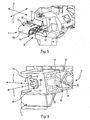
- FIGS. 4a to 4c illustrate the relative movements of the support frame 1 and the attachment flange 2 in case of shocks.
- the flange 2 is in the housing 10 and the pin 22 is in the light 21.
- the housing 10 is of parallelepipedal shape. It comprises a bottom wall 30 which can stop for the flange 2. It opens towards the front (in the X direction) and towards the side, at a face opposite its side wall 15, to accommodate the flange 2. It guides the support armature 1 in translation, in the direction X, relative to the flange 1, throughout the shock.
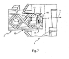
- the module is seen from the front, from above and from the side. To the figure 6 it is about the opposite angle of view. To the figure 7 it is again an angle of view from the front, in a direction very slightly shifted upwards and to the side with respect to the direction X.
- said flange 2 comprises, for example, a housing for the passage of said fixing rod 17 of the support frame. It may also include a housing 41 for the passage of a fastening rod, not shown, to the chassis of the vehicle.
- Said flange housing is, for example of round and / or oblong section.
- Said flange 1 may further comprise a housing 42 for fixing projectors or optical blocks of the vehicle.
- the projectors or optical blocks are not reported on the support frame 1 but on the attachment flange 2.
- said flange 2 has, for example, a flat portion 50, having the housing 42 for fixing the projector.
- Said flat portion is locally surmounted by a first block 52, here cellular and / or compartmentalized structure.
- Said first block 52 comprises the housing for attachment to the frame.
- a second block 53 here also of cellular and / or compartmentalized structure, is laterally attached to said first block 52.
- Said second block 53 comprises the housing 40 for the support arm of the support rod.
- Upper, lower and lateral faces of said second block 43 respectively define upper, lower and lateral walls, mentioned above, as well as said pin.
- the flange consists of a body of substantially parallelepiped shape.
- Said body is, in particular, of cellular and / or compartmentalized structure.
- Upper, lower and lateral faces of said body respectively define upper, lower, and lateral walls, mentioned above.
- the lateral face 50 opposite that defining the side wall 18 may be of rounded shape.
- the fixing rod 17 is constituted, for example, by a nut provided with a head 60. It cooperates with the flange 2, in particular, via a screw sleeve 61, locked in a compartment 62 (visible at figure 7 for the embodiment concerned) of said flange 2, the housing 40 for the passage of said fastening rod 17 opening into said compartment 62. Alternatively, it can be screwed into said housing 40, provided tapped.
- the head 60 of the nut bears against one side of the side wall 15 of the housing 10 of the support frame 1 and the face of the side wall 18 of the flange 2 bears against an opposite face of said side wall 15 of the housing 10 of the support frame 1.
- the invention also relates to a flange for a front-end module, as described above.
- Said flange 1 is, in particular, plastic material. It may however be any other type of materials.
- the invention also relates to a support frame for a front-end module, as described above. It can be monoblock or assembled from several elements.
- the one or more elements are, in particular, metal, plastic or hybrid metal-plastic material.
- the invention also relates to an assembly of a module 70 of front face as described above and a device 71 for shock absorption.
- Said assembly may be configured for a being mounted a block on the longitudinal members of the chassis of the vehicle.
- the shock absorption device 71 comprises, for example, a bumper beam 72 attached to the fixing plates 6. Said bumper beam 72 extends transversely between said fixing plates 6 to which it may be fixed by the intermediate shock absorber 74.
- the attachment flanges 2 of the front-face module are mounted on said fixing plates 6, in particular in their upper part.
Landscapes
- Engineering & Computer Science (AREA)
- Chemical & Material Sciences (AREA)
- Combustion & Propulsion (AREA)
- Transportation (AREA)
- Mechanical Engineering (AREA)
- Body Structure For Vehicles (AREA)
- Arrangement Or Mounting Of Propulsion Units For Vehicles (AREA)
- Motor Or Generator Frames (AREA)
- Lighting Device Outwards From Vehicle And Optical Signal (AREA)
Claims (14)
- Frontend-Modul eines Fahrzeugs, insbesondere eines Kraftfahrzeugs, das ein Traggerüst (1) und mindestens einen Flansch (2) zur Befestigung des Traggerüsts (1) an einem Fahrwerk des Fahrzeugs enthält, wobei der Flansch (2) konfiguriert ist, eine freie Positionierung des Moduls bezüglich des Fahrwerks in einer Ebene orthogonal zu einer Fahrtrichtung X des Fahrzeugs sowie eine Befestigung des Moduls am Fahrwerk gemäß der Positionierung zu erlauben, wobei der Flansch (2) und das Traggerüst (1) gegenseitig konfiguriert sind, aneinander befestigt zu werden und gleichzeitig eine Verschiebung zueinander gemäß der Richtung X im Fall eines Aufpralls zu erlauben, dadurch gekennzeichnet, dass das Traggerüst (1) mit einer Aufnahme (10) versehen ist, um den Flansch (2) aufzunehmen, wobei die Aufnahme (10) konfiguriert ist, einerseits eine Befestigung zwischen dem Flansch (2) und dem Traggerüst (1) gemäß einer Krafteinwirkung gegebener Richtung, die eine Komponente in einer waagrechten Richtung Y und orthogonal zur Fahrtrichtung X des Fahrzeugs aufweist, und andererseits eine Führung des Traggerüsts (1) bezüglich des Fahrwerks gemäß der Fahrtrichtung des Fahrzeugs im Fall eines Aufpralls zu erlauben.
- Modul nach Anspruch 1, wobei die Aufnahme (10) eine obere Führungswand (11) und/oder eine untere Führungswand (12) enthält.
- Modul nach Anspruch 2, wobei die untere Führungswand (12) dazu bestimmt ist, mit einer unteren Wand (14) des Flanschs (2) zusammenzuwirken, um im Fall einer auf das Traggerüst nach oben ausgeübten Kraft als Anschlag zu wirken.
- Modul nach Anspruch 2, wobei die obere Führungswand (11) dazu bestimmt ist, mit einer oberen Wand (13) des Flanschs (2) zusammenzuwirken, um als Träger für das Traggerüst (1) zu dienen.
- Modul nach einem der vorhergehenden Ansprüche, wobei die Aufnahme (10) eine Seitenwand (15) enthält, die mit einem Durchgangsschlitz (16) einer Befestigungsstange (17) des Traggerüsts (1) versehen ist, wobei die Stange (17) in der der Befestigungskraft gegebenen Richtung ausgerichtet ist.
- Modul nach Anspruch 5, wobei der Schlitz (16) eine Form aufweist, die sich in der Fahrtrichtung X des Fahrzeugs ausweitet.
- Modul nach einem der vorhergehenden Ansprüche, wobei die Aufnahme (10) eine Bodenwand (20) aufweist, die mit einem Loch (21) versehen ist, das dazu bestimmt ist, gemäß der Fahrachse X des Fahrzeugs ausgerichtet zu sein und mit einem Führungszapfen (22) des Befestigungsflanschs (2) zusammenwirkt.
- Modul nach einem der Ansprüche 5 bis 7, wobei der Flansch (2) eine Aufnahme (40) für den Durchgang der Befestigungsstange des Traggerüsts (l) enthält.
- Modul nach einem der vorhergehenden Ansprüche, wobei der Flansch (2) eine Aufnahme für den Durchgang einer Befestigungsstange am Fahrwerk des Fahrzeugs enthält.
- Modul nach einem der vorhergehenden Ansprüche, wobei der Flansch eine Aufnahme (42) zur Befestigung von Scheinwerfern oder Optikblöcken des Fahrzeugs enthält.
- Flansch (2) eines Frontend-Moduls nach einem der vorhergehenden Ansprüche.
- Traggerüst (1) eines Frontend-Moduls nach einem der vorhergehenden Ansprüche.
- Einheit aus einem Frontend-Modul (70) nach einem der Ansprüche 1 bis 10 und einer stoßabsorbierenden Vorrichtung (71).
- Einheit nach Anspruch 13, wobei die stoßabsorbierende Vorrichtung (71) Befestigungsplatten (6) eines Stoßfängerbalkens (72) enthält, und wobei der oder die Befestigungsflansche (2) an den Platten (6) befestigt sind.
Applications Claiming Priority (2)
| Application Number | Priority Date | Filing Date | Title |
|---|---|---|---|
| FR1156829A FR2978413B1 (fr) | 2011-07-26 | 2011-07-26 | Module de face avant de vehicule, notamment vehicule automobile |
| PCT/EP2012/064488 WO2013014148A1 (fr) | 2011-07-26 | 2012-07-24 | Module de face avant de vehicule, notamment vehicule automobile |
Publications (2)
| Publication Number | Publication Date |
|---|---|
| EP2736792A1 EP2736792A1 (de) | 2014-06-04 |
| EP2736792B1 true EP2736792B1 (de) | 2015-08-12 |
Family
ID=46548490
Family Applications (1)
| Application Number | Title | Priority Date | Filing Date |
|---|---|---|---|
| EP12737832.1A Not-in-force EP2736792B1 (de) | 2011-07-26 | 2012-07-24 | Frontendmodul für ein fahrzeug, insbesondere ein kraftfahrzeug |
Country Status (8)
| Country | Link |
|---|---|
| US (1) | US8998300B2 (de) |
| EP (1) | EP2736792B1 (de) |
| JP (1) | JP6026532B2 (de) |
| CN (1) | CN103930337B (de) |
| BR (1) | BR112014001981B1 (de) |
| ES (1) | ES2549958T3 (de) |
| FR (1) | FR2978413B1 (de) |
| WO (1) | WO2013014148A1 (de) |
Families Citing this family (4)
| Publication number | Priority date | Publication date | Assignee | Title |
|---|---|---|---|---|
| US9944219B2 (en) * | 2015-11-18 | 2018-04-17 | Ford Global Technologies, Llc | Headlamp module slip plane bracket |
| KR102663542B1 (ko) * | 2019-05-07 | 2024-05-03 | 현대자동차주식회사 | 차량의 프런트엔드모듈 프레임 |
| US12030571B2 (en) | 2019-12-10 | 2024-07-09 | Ford Global Technologies, Llc | Setting bracket for bolster adjustment |
| CN113548135B (zh) * | 2021-07-20 | 2022-04-15 | 安徽江淮汽车集团股份有限公司 | 一种车辆y基准平面定位装置 |
Family Cites Families (11)
| Publication number | Priority date | Publication date | Assignee | Title |
|---|---|---|---|---|
| DE10260171B4 (de) * | 2002-12-20 | 2013-06-06 | Volkswagen Ag | Kraftfahrzeug mit wegtauchendem Kühlermodul |
| US7213873B2 (en) * | 2004-03-25 | 2007-05-08 | Mazda Motor Corporation | Vehicle front-part structure |
| JP4453511B2 (ja) * | 2004-04-28 | 2010-04-21 | トヨタ自動車株式会社 | 車両用冷却系支持構造 |
| JP4853627B2 (ja) * | 2005-05-23 | 2012-01-11 | マツダ株式会社 | 自動車のシュラウド支持構造 |
| DE102005058180A1 (de) * | 2005-12-05 | 2007-06-06 | Peguform Gmbh | Frontendmodul für ein Kraftfahrzeug mit einer energieabsorbierenden Schutzfunktion für ein Kühlmodul |
| JP4797726B2 (ja) * | 2006-03-20 | 2011-10-19 | マツダ株式会社 | 自動車の前部構造 |
| JP4499133B2 (ja) * | 2006-11-01 | 2010-07-07 | カルソニックカンセイ株式会社 | 熱交換器の支持構造 |
| JP5029328B2 (ja) * | 2007-12-05 | 2012-09-19 | マツダ株式会社 | 自動車の前部車体構造 |
| JP5308926B2 (ja) * | 2009-06-10 | 2013-10-09 | 豊田鉄工株式会社 | 車両用冷却ユニットの支持構造 |
| DE102009058275A1 (de) * | 2009-12-14 | 2011-06-16 | GM Global Technology Operations LLC, ( n. d. Ges. d. Staates Delaware ), Detroit | Frontaufbau für ein Kraftfahrzeug |
| US8613338B2 (en) * | 2010-06-18 | 2013-12-24 | Cnh America Llc | Flat plate front frame for a tractor having ballast, bumper, and tow cable connections |
-
2011
- 2011-07-26 FR FR1156829A patent/FR2978413B1/fr not_active Expired - Fee Related
-
2012
- 2012-07-24 WO PCT/EP2012/064488 patent/WO2013014148A1/fr not_active Ceased
- 2012-07-24 ES ES12737832.1T patent/ES2549958T3/es active Active
- 2012-07-24 CN CN201280047004.4A patent/CN103930337B/zh not_active Expired - Fee Related
- 2012-07-24 EP EP12737832.1A patent/EP2736792B1/de not_active Not-in-force
- 2012-07-24 BR BR112014001981-9A patent/BR112014001981B1/pt not_active IP Right Cessation
- 2012-07-24 JP JP2014522058A patent/JP6026532B2/ja not_active Expired - Fee Related
- 2012-07-24 US US14/234,794 patent/US8998300B2/en active Active
Also Published As
| Publication number | Publication date |
|---|---|
| JP6026532B2 (ja) | 2016-11-16 |
| US20140197661A1 (en) | 2014-07-17 |
| US8998300B2 (en) | 2015-04-07 |
| FR2978413B1 (fr) | 2014-12-12 |
| BR112014001981A2 (pt) | 2017-02-21 |
| WO2013014148A1 (fr) | 2013-01-31 |
| BR112014001981A8 (pt) | 2018-08-28 |
| JP2014523369A (ja) | 2014-09-11 |
| CN103930337B (zh) | 2016-08-31 |
| CN103930337A (zh) | 2014-07-16 |
| FR2978413A1 (fr) | 2013-02-01 |
| BR112014001981B1 (pt) | 2021-07-20 |
| ES2549958T3 (es) | 2015-11-03 |
| EP2736792A1 (de) | 2014-06-04 |
Similar Documents
| Publication | Publication Date | Title |
|---|---|---|
| FR2931417A1 (fr) | Dispositif d'absorption de choc et face avant comportant un tel dispositif | |
| EP2736792B1 (de) | Frontendmodul für ein fahrzeug, insbesondere ein kraftfahrzeug | |
| FR2887508A1 (fr) | Poutre d'absorption d'energie, notamment pour vehicule automobile, et vehicule automobile equipe d'une telle poutre | |
| FR2971756A1 (fr) | Support d'enrouleur de ceinture de securite. | |
| WO2002102645A1 (fr) | Face avant de vehicule automobile avec equipements integres | |
| EP1916152B2 (de) | Vorderstruktur eines Kraftfahrzeugs und damit ausgestattetes Kraftfahrzeug | |
| EP1865253A1 (de) | Anordnung aus einer Beleuchtungsblockhalterung und einem Kotflügel eines Kraftfahrzeugs und Halterung, die zu einer solchen Anordnung gehört | |
| FR2867734A1 (fr) | Dispositif de fixation d'un bloc optique sur la structure d'un vehicule automobile, integrant des moyens d'amortissement d'un choc pieton | |
| FR2894555A1 (fr) | Systeme de fixation d'un module de refroidissement et vehicule muni d'un tel systeme | |
| EP2736793B1 (de) | Kopfmodul für ein kraftfahrzeug | |
| FR2912371A1 (fr) | Dispositif de bloc avant de vehicule automobile | |
| FR3120046A1 (fr) | Ensemble absorbeur de chocs pour véhicule automobile | |
| EP3350064B1 (de) | Tragstruktur für ein frontendmodul eines kraftfahrzeugs und frontendmodul mit der trägerstruktur | |
| FR3086227A1 (fr) | Support de projecteur de vehicule automobile. | |
| EP2176093B1 (de) | Stossfängerschild | |
| FR3147998A1 (fr) | Support multifonction pour véhicule automobile | |
| FR3083757A1 (fr) | Guide d'air en materiau polymere expanse a zone d'appui sur une traverse extreme avant | |
| FR3037552A1 (fr) | Structure de support pour module de face avant d'un vehicule et module de face avant comprenant ladite structure de support | |
| FR3062840A1 (fr) | Caisse de vehicule automobile comprenant une piece de renfort, et vehicule automobile comprenant une telle caisse | |
| FR3164162A1 (fr) | Pare-chocs de véhicule automobile avec blocage d’un radar | |
| FR3070147B1 (fr) | Dispositif de fixation d’un equipement sur un chassis de vehicule automobile ayant une cinematique de choc en rotation | |
| EP4538151A1 (de) | Anordnung für ein kraftfahrzeug mit einer verriegelungsanordnung einer haube und einem tragrahmenelement | |
| FR3138897A1 (fr) | Longeron de véhicule automobile à renforcement interne et structure de plancher de véhicule équipée d’un tel longeron | |
| FR3165814A1 (fr) | Arrangement pour véhicule automobile. | |
| WO2025046177A1 (fr) | Structure de véhicule automobile avec troisième voie renforcée |
Legal Events
| Date | Code | Title | Description |
|---|---|---|---|
| PUAI | Public reference made under article 153(3) epc to a published international application that has entered the european phase |
Free format text: ORIGINAL CODE: 0009012 |
|
| 17P | Request for examination filed |
Effective date: 20140121 |
|
| AK | Designated contracting states |
Kind code of ref document: A1 Designated state(s): AL AT BE BG CH CY CZ DE DK EE ES FI FR GB GR HR HU IE IS IT LI LT LU LV MC MK MT NL NO PL PT RO RS SE SI SK SM TR |
|
| DAX | Request for extension of the european patent (deleted) | ||
| GRAP | Despatch of communication of intention to grant a patent |
Free format text: ORIGINAL CODE: EPIDOSNIGR1 |
|
| INTG | Intention to grant announced |
Effective date: 20150219 |
|
| GRAS | Grant fee paid |
Free format text: ORIGINAL CODE: EPIDOSNIGR3 |
|
| GRAA | (expected) grant |
Free format text: ORIGINAL CODE: 0009210 |
|
| AK | Designated contracting states |
Kind code of ref document: B1 Designated state(s): AL AT BE BG CH CY CZ DE DK EE ES FI FR GB GR HR HU IE IS IT LI LT LU LV MC MK MT NL NO PL PT RO RS SE SI SK SM TR |
|
| REG | Reference to a national code |
Ref country code: GB Ref legal event code: FG4D Free format text: NOT ENGLISH |
|
| REG | Reference to a national code |
Ref country code: CH Ref legal event code: EP |
|
| REG | Reference to a national code |
Ref country code: AT Ref legal event code: REF Ref document number: 741880 Country of ref document: AT Kind code of ref document: T Effective date: 20150815 |
|
| REG | Reference to a national code |
Ref country code: IE Ref legal event code: FG4D Free format text: LANGUAGE OF EP DOCUMENT: FRENCH |
|
| REG | Reference to a national code |
Ref country code: DE Ref legal event code: R096 Ref document number: 602012009610 Country of ref document: DE |
|
| REG | Reference to a national code |
Ref country code: ES Ref legal event code: FG2A Ref document number: 2549958 Country of ref document: ES Kind code of ref document: T3 Effective date: 20151103 |
|
| REG | Reference to a national code |
Ref country code: LT Ref legal event code: MG4D |
|
| REG | Reference to a national code |
Ref country code: AT Ref legal event code: MK05 Ref document number: 741880 Country of ref document: AT Kind code of ref document: T Effective date: 20150812 |
|
| REG | Reference to a national code |
Ref country code: NL Ref legal event code: MP Effective date: 20150812 |
|
| PG25 | Lapsed in a contracting state [announced via postgrant information from national office to epo] |
Ref country code: LT Free format text: LAPSE BECAUSE OF FAILURE TO SUBMIT A TRANSLATION OF THE DESCRIPTION OR TO PAY THE FEE WITHIN THE PRESCRIBED TIME-LIMIT Effective date: 20150812 Ref country code: LV Free format text: LAPSE BECAUSE OF FAILURE TO SUBMIT A TRANSLATION OF THE DESCRIPTION OR TO PAY THE FEE WITHIN THE PRESCRIBED TIME-LIMIT Effective date: 20150812 Ref country code: NO Free format text: LAPSE BECAUSE OF FAILURE TO SUBMIT A TRANSLATION OF THE DESCRIPTION OR TO PAY THE FEE WITHIN THE PRESCRIBED TIME-LIMIT Effective date: 20151112 Ref country code: FI Free format text: LAPSE BECAUSE OF FAILURE TO SUBMIT A TRANSLATION OF THE DESCRIPTION OR TO PAY THE FEE WITHIN THE PRESCRIBED TIME-LIMIT Effective date: 20150812 |
|
| PG25 | Lapsed in a contracting state [announced via postgrant information from national office to epo] |
Ref country code: HR Free format text: LAPSE BECAUSE OF FAILURE TO SUBMIT A TRANSLATION OF THE DESCRIPTION OR TO PAY THE FEE WITHIN THE PRESCRIBED TIME-LIMIT Effective date: 20150812 Ref country code: PT Free format text: LAPSE BECAUSE OF FAILURE TO SUBMIT A TRANSLATION OF THE DESCRIPTION OR TO PAY THE FEE WITHIN THE PRESCRIBED TIME-LIMIT Effective date: 20151214 Ref country code: AT Free format text: LAPSE BECAUSE OF FAILURE TO SUBMIT A TRANSLATION OF THE DESCRIPTION OR TO PAY THE FEE WITHIN THE PRESCRIBED TIME-LIMIT Effective date: 20150812 Ref country code: SE Free format text: LAPSE BECAUSE OF FAILURE TO SUBMIT A TRANSLATION OF THE DESCRIPTION OR TO PAY THE FEE WITHIN THE PRESCRIBED TIME-LIMIT Effective date: 20150812 Ref country code: PL Free format text: LAPSE BECAUSE OF FAILURE TO SUBMIT A TRANSLATION OF THE DESCRIPTION OR TO PAY THE FEE WITHIN THE PRESCRIBED TIME-LIMIT Effective date: 20150812 Ref country code: RS Free format text: LAPSE BECAUSE OF FAILURE TO SUBMIT A TRANSLATION OF THE DESCRIPTION OR TO PAY THE FEE WITHIN THE PRESCRIBED TIME-LIMIT Effective date: 20150812 Ref country code: IS Free format text: LAPSE BECAUSE OF FAILURE TO SUBMIT A TRANSLATION OF THE DESCRIPTION OR TO PAY THE FEE WITHIN THE PRESCRIBED TIME-LIMIT Effective date: 20151212 |
|
| PG25 | Lapsed in a contracting state [announced via postgrant information from national office to epo] |
Ref country code: NL Free format text: LAPSE BECAUSE OF FAILURE TO SUBMIT A TRANSLATION OF THE DESCRIPTION OR TO PAY THE FEE WITHIN THE PRESCRIBED TIME-LIMIT Effective date: 20150812 |
|
| PG25 | Lapsed in a contracting state [announced via postgrant information from national office to epo] |
Ref country code: IT Free format text: LAPSE BECAUSE OF FAILURE TO SUBMIT A TRANSLATION OF THE DESCRIPTION OR TO PAY THE FEE WITHIN THE PRESCRIBED TIME-LIMIT Effective date: 20150812 Ref country code: DK Free format text: LAPSE BECAUSE OF FAILURE TO SUBMIT A TRANSLATION OF THE DESCRIPTION OR TO PAY THE FEE WITHIN THE PRESCRIBED TIME-LIMIT Effective date: 20150812 Ref country code: CZ Free format text: LAPSE BECAUSE OF FAILURE TO SUBMIT A TRANSLATION OF THE DESCRIPTION OR TO PAY THE FEE WITHIN THE PRESCRIBED TIME-LIMIT Effective date: 20150812 Ref country code: SK Free format text: LAPSE BECAUSE OF FAILURE TO SUBMIT A TRANSLATION OF THE DESCRIPTION OR TO PAY THE FEE WITHIN THE PRESCRIBED TIME-LIMIT Effective date: 20150812 Ref country code: EE Free format text: LAPSE BECAUSE OF FAILURE TO SUBMIT A TRANSLATION OF THE DESCRIPTION OR TO PAY THE FEE WITHIN THE PRESCRIBED TIME-LIMIT Effective date: 20150812 |
|
| REG | Reference to a national code |
Ref country code: DE Ref legal event code: R097 Ref document number: 602012009610 Country of ref document: DE |
|
| PG25 | Lapsed in a contracting state [announced via postgrant information from national office to epo] |
Ref country code: RO Free format text: LAPSE BECAUSE OF FAILURE TO SUBMIT A TRANSLATION OF THE DESCRIPTION OR TO PAY THE FEE WITHIN THE PRESCRIBED TIME-LIMIT Effective date: 20150812 |
|
| PLBE | No opposition filed within time limit |
Free format text: ORIGINAL CODE: 0009261 |
|
| STAA | Information on the status of an ep patent application or granted ep patent |
Free format text: STATUS: NO OPPOSITION FILED WITHIN TIME LIMIT |
|
| 26N | No opposition filed |
Effective date: 20160513 |
|
| REG | Reference to a national code |
Ref country code: FR Ref legal event code: PLFP Year of fee payment: 5 |
|
| PG25 | Lapsed in a contracting state [announced via postgrant information from national office to epo] |
Ref country code: SI Free format text: LAPSE BECAUSE OF FAILURE TO SUBMIT A TRANSLATION OF THE DESCRIPTION OR TO PAY THE FEE WITHIN THE PRESCRIBED TIME-LIMIT Effective date: 20150812 |
|
| PG25 | Lapsed in a contracting state [announced via postgrant information from national office to epo] |
Ref country code: BE Free format text: LAPSE BECAUSE OF NON-PAYMENT OF DUE FEES Effective date: 20160731 |
|
| REG | Reference to a national code |
Ref country code: CH Ref legal event code: PL |
|
| GBPC | Gb: european patent ceased through non-payment of renewal fee |
Effective date: 20160724 |
|
| PG25 | Lapsed in a contracting state [announced via postgrant information from national office to epo] |
Ref country code: MC Free format text: LAPSE BECAUSE OF FAILURE TO SUBMIT A TRANSLATION OF THE DESCRIPTION OR TO PAY THE FEE WITHIN THE PRESCRIBED TIME-LIMIT Effective date: 20150812 |
|
| PG25 | Lapsed in a contracting state [announced via postgrant information from national office to epo] |
Ref country code: CH Free format text: LAPSE BECAUSE OF NON-PAYMENT OF DUE FEES Effective date: 20160731 Ref country code: LI Free format text: LAPSE BECAUSE OF NON-PAYMENT OF DUE FEES Effective date: 20160731 |
|
| REG | Reference to a national code |
Ref country code: IE Ref legal event code: MM4A |
|
| PG25 | Lapsed in a contracting state [announced via postgrant information from national office to epo] |
Ref country code: GB Free format text: LAPSE BECAUSE OF NON-PAYMENT OF DUE FEES Effective date: 20160724 |
|
| PG25 | Lapsed in a contracting state [announced via postgrant information from national office to epo] |
Ref country code: IE Free format text: LAPSE BECAUSE OF NON-PAYMENT OF DUE FEES Effective date: 20160724 |
|
| REG | Reference to a national code |
Ref country code: FR Ref legal event code: PLFP Year of fee payment: 6 |
|
| PG25 | Lapsed in a contracting state [announced via postgrant information from national office to epo] |
Ref country code: LU Free format text: LAPSE BECAUSE OF NON-PAYMENT OF DUE FEES Effective date: 20160724 |
|
| PG25 | Lapsed in a contracting state [announced via postgrant information from national office to epo] |
Ref country code: HU Free format text: LAPSE BECAUSE OF FAILURE TO SUBMIT A TRANSLATION OF THE DESCRIPTION OR TO PAY THE FEE WITHIN THE PRESCRIBED TIME-LIMIT; INVALID AB INITIO Effective date: 20120724 Ref country code: SM Free format text: LAPSE BECAUSE OF FAILURE TO SUBMIT A TRANSLATION OF THE DESCRIPTION OR TO PAY THE FEE WITHIN THE PRESCRIBED TIME-LIMIT Effective date: 20150812 Ref country code: CY Free format text: LAPSE BECAUSE OF FAILURE TO SUBMIT A TRANSLATION OF THE DESCRIPTION OR TO PAY THE FEE WITHIN THE PRESCRIBED TIME-LIMIT Effective date: 20150812 |
|
| PG25 | Lapsed in a contracting state [announced via postgrant information from national office to epo] |
Ref country code: MK Free format text: LAPSE BECAUSE OF FAILURE TO SUBMIT A TRANSLATION OF THE DESCRIPTION OR TO PAY THE FEE WITHIN THE PRESCRIBED TIME-LIMIT Effective date: 20150812 Ref country code: MT Free format text: LAPSE BECAUSE OF FAILURE TO SUBMIT A TRANSLATION OF THE DESCRIPTION OR TO PAY THE FEE WITHIN THE PRESCRIBED TIME-LIMIT Effective date: 20150812 Ref country code: GR Free format text: LAPSE BECAUSE OF FAILURE TO SUBMIT A TRANSLATION OF THE DESCRIPTION OR TO PAY THE FEE WITHIN THE PRESCRIBED TIME-LIMIT Effective date: 20150812 |
|
| REG | Reference to a national code |
Ref country code: FR Ref legal event code: PLFP Year of fee payment: 7 |
|
| PG25 | Lapsed in a contracting state [announced via postgrant information from national office to epo] |
Ref country code: BG Free format text: LAPSE BECAUSE OF FAILURE TO SUBMIT A TRANSLATION OF THE DESCRIPTION OR TO PAY THE FEE WITHIN THE PRESCRIBED TIME-LIMIT Effective date: 20150812 |
|
| PG25 | Lapsed in a contracting state [announced via postgrant information from national office to epo] |
Ref country code: AL Free format text: LAPSE BECAUSE OF FAILURE TO SUBMIT A TRANSLATION OF THE DESCRIPTION OR TO PAY THE FEE WITHIN THE PRESCRIBED TIME-LIMIT Effective date: 20150812 Ref country code: TR Free format text: LAPSE BECAUSE OF FAILURE TO SUBMIT A TRANSLATION OF THE DESCRIPTION OR TO PAY THE FEE WITHIN THE PRESCRIBED TIME-LIMIT Effective date: 20150812 |
|
| PGFP | Annual fee paid to national office [announced via postgrant information from national office to epo] |
Ref country code: ES Payment date: 20210812 Year of fee payment: 10 |
|
| P01 | Opt-out of the competence of the unified patent court (upc) registered |
Effective date: 20230528 |
|
| REG | Reference to a national code |
Ref country code: ES Ref legal event code: FD2A Effective date: 20230906 |
|
| PG25 | Lapsed in a contracting state [announced via postgrant information from national office to epo] |
Ref country code: ES Free format text: LAPSE BECAUSE OF NON-PAYMENT OF DUE FEES Effective date: 20220725 |
|
| PGFP | Annual fee paid to national office [announced via postgrant information from national office to epo] |
Ref country code: FR Payment date: 20230727 Year of fee payment: 12 Ref country code: DE Payment date: 20230712 Year of fee payment: 12 |
|
| REG | Reference to a national code |
Ref country code: DE Ref legal event code: R119 Ref document number: 602012009610 Country of ref document: DE |
|
| PG25 | Lapsed in a contracting state [announced via postgrant information from national office to epo] |
Ref country code: DE Free format text: LAPSE BECAUSE OF NON-PAYMENT OF DUE FEES Effective date: 20250201 |
|
| PG25 | Lapsed in a contracting state [announced via postgrant information from national office to epo] |
Ref country code: FR Free format text: LAPSE BECAUSE OF NON-PAYMENT OF DUE FEES Effective date: 20240731 |