EP2736692B1 - Produktionsanlage mit einem transportsystem zur verarbeitung von länglichen produkten, insbesondere windturbinenschaufeln, mit verlängerten formkörperanordnungen - Google Patents
Produktionsanlage mit einem transportsystem zur verarbeitung von länglichen produkten, insbesondere windturbinenschaufeln, mit verlängerten formkörperanordnungen Download PDFInfo
- Publication number
- EP2736692B1 EP2736692B1 EP12746010.3A EP12746010A EP2736692B1 EP 2736692 B1 EP2736692 B1 EP 2736692B1 EP 12746010 A EP12746010 A EP 12746010A EP 2736692 B1 EP2736692 B1 EP 2736692B1
- Authority
- EP
- European Patent Office
- Prior art keywords
- support member
- elongated
- mould
- elongated support
- mould assembly
- Prior art date
- Legal status (The legal status is an assumption and is not a legal conclusion. Google has not performed a legal analysis and makes no representation as to the accuracy of the status listed.)
- Active
Links
Images




Classifications
-
- F—MECHANICAL ENGINEERING; LIGHTING; HEATING; WEAPONS; BLASTING
- F01—MACHINES OR ENGINES IN GENERAL; ENGINE PLANTS IN GENERAL; STEAM ENGINES
- F01D—NON-POSITIVE DISPLACEMENT MACHINES OR ENGINES, e.g. STEAM TURBINES
- F01D5/00—Blades; Blade-carrying members; Heating, heat-insulating, cooling or antivibration means on the blades or the members
- F01D5/12—Blades
- F01D5/14—Form or construction
- F01D5/147—Construction, i.e. structural features, e.g. of weight-saving hollow blades
-
- B—PERFORMING OPERATIONS; TRANSPORTING
- B29—WORKING OF PLASTICS; WORKING OF SUBSTANCES IN A PLASTIC STATE IN GENERAL
- B29C—SHAPING OR JOINING OF PLASTICS; SHAPING OF MATERIAL IN A PLASTIC STATE, NOT OTHERWISE PROVIDED FOR; AFTER-TREATMENT OF THE SHAPED PRODUCTS, e.g. REPAIRING
- B29C33/00—Moulds or cores; Details thereof or accessories therefor
- B29C33/20—Opening, closing or clamping
- B29C33/26—Opening, closing or clamping by pivotal movement
-
- B—PERFORMING OPERATIONS; TRANSPORTING
- B29—WORKING OF PLASTICS; WORKING OF SUBSTANCES IN A PLASTIC STATE IN GENERAL
- B29C—SHAPING OR JOINING OF PLASTICS; SHAPING OF MATERIAL IN A PLASTIC STATE, NOT OTHERWISE PROVIDED FOR; AFTER-TREATMENT OF THE SHAPED PRODUCTS, e.g. REPAIRING
- B29C31/00—Handling, e.g. feeding of the material to be shaped, storage of plastics material before moulding; Automation, i.e. automated handling lines in plastics processing plants, e.g. using manipulators or robots
- B29C31/04—Feeding of the material to be moulded, e.g. into a mould cavity
-
- B—PERFORMING OPERATIONS; TRANSPORTING
- B29—WORKING OF PLASTICS; WORKING OF SUBSTANCES IN A PLASTIC STATE IN GENERAL
- B29C—SHAPING OR JOINING OF PLASTICS; SHAPING OF MATERIAL IN A PLASTIC STATE, NOT OTHERWISE PROVIDED FOR; AFTER-TREATMENT OF THE SHAPED PRODUCTS, e.g. REPAIRING
- B29C70/00—Shaping composites, i.e. plastics material comprising reinforcements, fillers or preformed parts, e.g. inserts
- B29C70/04—Shaping composites, i.e. plastics material comprising reinforcements, fillers or preformed parts, e.g. inserts comprising reinforcements only, e.g. self-reinforcing plastics
- B29C70/28—Shaping operations therefor
- B29C70/30—Shaping by lay-up, i.e. applying fibres, tape or broadsheet on a mould, former or core; Shaping by spray-up, i.e. spraying of fibres on a mould, former or core
- B29C70/38—Automated lay-up, e.g. using robots, laying filaments according to predetermined patterns
-
- F—MECHANICAL ENGINEERING; LIGHTING; HEATING; WEAPONS; BLASTING
- F03—MACHINES OR ENGINES FOR LIQUIDS; WIND, SPRING, OR WEIGHT MOTORS; PRODUCING MECHANICAL POWER OR A REACTIVE PROPULSIVE THRUST, NOT OTHERWISE PROVIDED FOR
- F03D—WIND MOTORS
- F03D1/00—Wind motors with rotation axis substantially parallel to the air flow entering the rotor
- F03D1/06—Rotors
- F03D1/065—Rotors characterised by their construction elements
- F03D1/0675—Rotors characterised by their construction elements of the blades
-
- B—PERFORMING OPERATIONS; TRANSPORTING
- B29—WORKING OF PLASTICS; WORKING OF SUBSTANCES IN A PLASTIC STATE IN GENERAL
- B29L—INDEXING SCHEME ASSOCIATED WITH SUBCLASS B29C, RELATING TO PARTICULAR ARTICLES
- B29L2031/00—Other particular articles
- B29L2031/08—Blades for rotors, stators, fans, turbines or the like, e.g. screw propellers
- B29L2031/082—Blades, e.g. for helicopters
- B29L2031/085—Wind turbine blades
-
- F—MECHANICAL ENGINEERING; LIGHTING; HEATING; WEAPONS; BLASTING
- F05—INDEXING SCHEMES RELATING TO ENGINES OR PUMPS IN VARIOUS SUBCLASSES OF CLASSES F01-F04
- F05B—INDEXING SCHEME RELATING TO WIND, SPRING, WEIGHT, INERTIA OR LIKE MOTORS, TO MACHINES OR ENGINES FOR LIQUIDS COVERED BY SUBCLASSES F03B, F03D AND F03G
- F05B2230/00—Manufacture
- F05B2230/20—Manufacture essentially without removing material
- F05B2230/21—Manufacture essentially without removing material by casting
-
- Y—GENERAL TAGGING OF NEW TECHNOLOGICAL DEVELOPMENTS; GENERAL TAGGING OF CROSS-SECTIONAL TECHNOLOGIES SPANNING OVER SEVERAL SECTIONS OF THE IPC; TECHNICAL SUBJECTS COVERED BY FORMER USPC CROSS-REFERENCE ART COLLECTIONS [XRACs] AND DIGESTS
- Y02—TECHNOLOGIES OR APPLICATIONS FOR MITIGATION OR ADAPTATION AGAINST CLIMATE CHANGE
- Y02E—REDUCTION OF GREENHOUSE GAS [GHG] EMISSIONS, RELATED TO ENERGY GENERATION, TRANSMISSION OR DISTRIBUTION
- Y02E10/00—Energy generation through renewable energy sources
- Y02E10/70—Wind energy
- Y02E10/72—Wind turbines with rotation axis in wind direction
-
- Y—GENERAL TAGGING OF NEW TECHNOLOGICAL DEVELOPMENTS; GENERAL TAGGING OF CROSS-SECTIONAL TECHNOLOGIES SPANNING OVER SEVERAL SECTIONS OF THE IPC; TECHNICAL SUBJECTS COVERED BY FORMER USPC CROSS-REFERENCE ART COLLECTIONS [XRACs] AND DIGESTS
- Y02—TECHNOLOGIES OR APPLICATIONS FOR MITIGATION OR ADAPTATION AGAINST CLIMATE CHANGE
- Y02P—CLIMATE CHANGE MITIGATION TECHNOLOGIES IN THE PRODUCTION OR PROCESSING OF GOODS
- Y02P70/00—Climate change mitigation technologies in the production process for final industrial or consumer products
- Y02P70/50—Manufacturing or production processes characterised by the final manufactured product
-
- Y—GENERAL TAGGING OF NEW TECHNOLOGICAL DEVELOPMENTS; GENERAL TAGGING OF CROSS-SECTIONAL TECHNOLOGIES SPANNING OVER SEVERAL SECTIONS OF THE IPC; TECHNICAL SUBJECTS COVERED BY FORMER USPC CROSS-REFERENCE ART COLLECTIONS [XRACs] AND DIGESTS
- Y10—TECHNICAL SUBJECTS COVERED BY FORMER USPC
- Y10T—TECHNICAL SUBJECTS COVERED BY FORMER US CLASSIFICATION
- Y10T29/00—Metal working
- Y10T29/37—Impeller making apparatus
-
- Y—GENERAL TAGGING OF NEW TECHNOLOGICAL DEVELOPMENTS; GENERAL TAGGING OF CROSS-SECTIONAL TECHNOLOGIES SPANNING OVER SEVERAL SECTIONS OF THE IPC; TECHNICAL SUBJECTS COVERED BY FORMER USPC CROSS-REFERENCE ART COLLECTIONS [XRACs] AND DIGESTS
- Y10—TECHNICAL SUBJECTS COVERED BY FORMER USPC
- Y10T—TECHNICAL SUBJECTS COVERED BY FORMER US CLASSIFICATION
- Y10T29/00—Metal working
- Y10T29/49—Method of mechanical manufacture
- Y10T29/49316—Impeller making
- Y10T29/49336—Blade making
Definitions
- the present invention relates to a production facility with a transport system, wherein elongated products, in particular wind turbine blades, are formed by using moulds that extend along the length of the elongated product and by combining the moulds to form the complete elongated product.
- Elongated products such as wind turbine blades
- a technique is frequently used, in which a first half of the elongated product is formed by applying layer after layer in one of the moulds and at the same time preparing the second half of the elongated product layer after layer in the second mould and finally combining the two moulds so as to join the two halves of the elongated product.
- the two halves have to be prepared on the basis of a specific process strategy with high precision, in particular when considering wind turbine blades, so that there is generally a continuous attempt in this field of industry to increasingly apply automated process techniques, which, for instance, require the usage of some sort of robot system, and the like.
- a corresponding robot system Due to the significant length of, for instance wind turbine blades, a corresponding robot system has to appropriately be positioned along the length of the elongated moulds, thereby typically requiring an adequate transport system.
- a corresponding transport system has to be configured in such a way that a movable part, which may carry a robot device and the like, can be positioned at any location along the length of the elongated mould, however, without unduly restricting accessibility of the mould by operators and workers.
- the two moulds may be accessed individually and independently by a robot device, which in turn may require an appropriate support assembly in the form of rails, and the like, which, on the one hand, allows access of the moulds during the preparation of the various layer systems, while on the other hand, the moulds may be brought into contact with each other so as to form the composite mould assembly and thus enable the joining of the two halves of the elongated product.
- a robot device which in turn may require an appropriate support assembly in the form of rails, and the like, which, on the one hand, allows access of the moulds during the preparation of the various layer systems, while on the other hand, the moulds may be brought into contact with each other so as to form the composite mould assembly and thus enable the joining of the two halves of the elongated product.
- the two mould assemblies are brought into contact with each other by providing an appropriate mould drive mechanism connected to a movable mould assembly, which is rotated around at least one axis of rotation in order to position the movable mould assembly above the non-movable mould assembly, thereby "closing" the composite mould assembly.
- the transport system comprises at least one centre rail positioned laterally between the movable and non-movable mould assemblies, wherein, however, the central position of this rail may significantly interfere with the rotational movement of the movable mould assembly.
- WO2011/035539 describes an automated production system for wind turbine blades, in which two gantries can be independently operated so as to allow each gantry to be positioned along the corresponding mould on the basis of a centre rail that is positioned at a height level selected so as to provide for superior accessibility by workers.
- the centre rail comprises gaps that are positioned such along the entire length of the centre rail that the various hinge mechanisms for rotating one of the moulds can move through the corresponding gaps when closing the mould.
- the gaps may be "bridged" upon moving the gantry by providing a specific wheel system that allows the crossing of the gaps without losing contact to the centre rail.
- the gaps can temporarily be closed by laterally moving corresponding bridge sections from a first position, allowing the crossing of the hinge mechanisms, into a second position, in which the gap in the centre rail is closed.
- WO 2010/129492 discloses an installation for moulding wind turbine blades in which two elongated mould halves are positioned longitudinally side-by-side. Plies of fiber reinforcing material are robotically placed in the moulds. Two gantries are located at the root end of each mould. The two gantries are independently movable along the length of the mould, and are used to carry out different operations during the molding cycle.
- CA 2762777 discloses a system including an installation for the manufacture of wind turbine blades by means of applying dry fiber "cloth” mats, above two die halves where respective halves or “shells” are formed making up the body of the desired blade when attached to one another.
- the installation consists of a common gantry structure arranged above the assembly of the two die halves, one of which is fixed and the other one being susceptible of being turned over onto the former to attach the "shells" formed therein in opposition.
- Respective individual gantry structures are further arranged above each of the die halves.
- each individual gantry structure has the same structural formation but a different width, such that one of them can be used with "cloth” mats having a width less than a certain value, whereas the other one can be used with "cloth” mats having a greater width.
- the object is solved by a production facility.
- the production facility comprises a first elongated mould assembly and a second elongated mould assembly extending in parallel to the first elongated mould assembly.
- the production facility comprises a transport system that comprises an elongated support member extending along and laterally between the first and second elongated mould assemblies.
- the transport system further comprises a movable part configured to be positioned at least along the first and second elongated mould assemblies by using the elongated support member.
- the transport system comprises a drive mechanism coupled to the elongated support member and configured to change a position of the elongated support member with respect to the first and second elongated mould assemblies.
- the inventive production facility thus comprises a transport system whose configuration is selected such that the elongated support member is appropriately positioned so as to enable an appropriate positioning of the movable part along the entire length of the mould assemblies, while at the same time enabling movement of the elongated support member.
- the position of the elongated support member with respect to the first and second mould assemblies may be changed, for instance in correlation to a corresponding phase of the overall fabrication process, for example selecting different height levels as may be considered advantageous for the specific stage of the production process, thereby for instance, providing superior accessibility of the mould assemblies by workers, robot devices, and the like.
- the production facility further comprises a mould drive mechanism coupled at least to the second elongated mould assembly and configured to position the second elongated mould assembly relatively to the first mould assembly so as to form a composite mould assembly.
- the second mould assembly can be positioned with respect to the first mould assembly so as to form a composite mould assembly, even highly complex fabrication processes can be implemented in the production facility, such as the fabrication of wind turbine blades, typically requiring accessibility of the first and second mould assemblies over the entire length by the movable part of the transport system. Furthermore, in combination with the capability of changing position of the support member generally an increased degree of flexibility in implementing automated manufacturing sequences is achieved.
- the drive mechanism is configured to perform a change of position of the elongated support member so as to position the elongated support member at a non-interference position that avoids interference with the positioning of the second elongated mould assembly relatively to the first mould assembly when forming the composite mould assembly.
- the drive mechanism not only provides for superior flexibility in appropriately positioning the support member, but also enables the support member to be positioned at the non-interference position so that generally a superior degree of freedom is achieved in appropriately configuring the mould drive mechanism, for instance with respect to the drive components, hinge mechanisms, and the like, since the support member as a whole is moved to a non-critical position.
- the mould drive mechanism is configured to rotate the second mould assembly around an axis of rotation extending along the first and second elongated mould assemblies. Consequently, a plurality of well established mechanical systems may be used for implementing a rotational movement on the basis of the mould drive mechanism, wherein in one illustrative embodiment, the mould drive mechanism is configured to rotate the second mould assembly around a single axis of rotation that extends along the first and second elongated mould assemblies.
- the moulds drive mechanism may have any appropriate configuration, for instance in terms of the hinge system, turn leverages, and the like.
- the drive mechanism is configured to perform change of position by initiating at least a translational movement of the elongated support member.
- a simple and robust construction of the drive mechanism may be implemented, since a linear movement can be realised by a plurality of well-established actuators, such as hydraulic cylinders, pneumatic cylinders, motors and gearbox combinations, and the like.
- the translational movement is a vertical movement. That is, the elongated support member may be lifted or lowered so as to appropriately position the support member in accordance with the process strategy to be applied upon forming the elongated product.
- the drive mechanism is configured to lift the elongated support member into the non-interference position. Consequently, the non-interference position may be selected to be well above the height level of the first and second mould assemblies, thereby also ensuring superior accessibility for workers and operators, even when moving the second mould assembly into the closed position.
- the drive mechanism is configured to lower the elongated support member into the non-interference position.
- the vertical movement may be implemented on the basis of robust mechanical components without requiring an installation, for instance, at the ceiling of the facility.
- the support member may be lowered into the non-interference position such that workers and operators may walk above the support member, which, for instance, may be accomplished by providing an appropriate recess and the floor of the facility.
- the support member may be positioned at a first height level during operation of the transport system, in which also superior accessibility of the mould assemblies may be achieved, while the second height level corresponding to the non-interference position may also allow substantially complete access of the space between the mould assemblies, when the support member is in the non-interference position.
- the non-interference position may also be used at any appropriate stage of the overall production process, even if the first and second mould assemblies do not form the composite mould assembly.
- the drive mechanism is configured to perform change of position by initiating at least a rotational movement of the elongated support member along an axis of rotation that extends along the first and second mould assemblies.
- a movement of the support member may be initiated in a very space efficient manner by using well-established actuators, such as electric motors, and the like.
- the drive assembly is configured to bring the elongated support member into the non-interference position by the rotational movement only.
- an efficient rotating mechanism may be implemented in order to select an appropriate position of the support member. That is, although only a single rotational movement is sufficient to bring the support member into the non-interference position, nevertheless any intermediate angular position may also be selected, if considered appropriate for enhancing accessibility of the space between the first and second mould assemblies.
- the drive mechanism and the mould drive mechanism are coupled and configured so as to perform the rotational movement while positioning the second elongated mould assembly relatively to the first mould assembly so as to form a composite mould assembly.
- the coupling of these drive mechanisms may reduce the number of required components and may also allow a very space efficient construction of the combined drive mechanism.
- by mechanically coupling these drive mechanisms it may automatically be ensured that the support member is moved into the non-interference position while the second mould assembly is brought into contact with the first mould assembly. If the positioning of the support member at the non-interference position requires a different angle of rotation compared to positioning the second mould assembly above the first mould assembly, a corresponding adaptation made readily be obtained by using an appropriate gearbox.
- first and second mould assemblies require an angle of rotation of approximately 180°, while it is advantageous to rotate the support member by an angle of approximately 90°, a corresponding 2:1 gear ratio may be implemented.
- the same drive components such as motors, hydraulic systems, and the like may be used for moving the support member and the second mould assembly, even if different angles of rotation are required.
- the transport system comprises an outer elongated support member extending along one of the first and second elongated mould assemblies.
- the transport system comprises a second outer elongated support member extending along the other one of the first and second elongated mould assemblies.
- first and second mould assemblies comprise mould half shelves for forming a wind turbine blade.
- the production facility is appropriately configured to form highly complex elongated products in the form of wind turbine blades, wherein the configuration of the transport system allows a high degree of automation, while still providing for superior flexibility and accessibility of the first and second mould assemblies during the fabrication process.
- the object is solved by a method for forming an elongated product, in particular a wind turbine blade, wherein elongated mould assemblies may be filled with appropriate materials on the basis of a transport system comprising a movable part that may be positioned along the length of the elongated mould assemblies by using an elongated support member.
- the elongated mould assemblies may be brought into a closed position by turning at least one of these elongated mould assemblies, wherein the support member is positioned in a non-interference position, thereby providing space for moving one or both of the elongated mould assemblies.
- the positioning of the elongated support member at the non-interference position and that an appropriate work position or at any intermediate position may be accomplished by a translational movement, for instance in the vertical or horizontal direction and/or by a rotational movement around an axis of rotation that is oriented along a length direction of the elongated mould assemblies.
- Figure 1 a schematically illustrates a top view of a production facility 100, in which are installed a first mould assembly 110a and a second mould assembly 110b, which are arranged in parallel to each other.
- the first and second mould assemblies 110a, 110b are elongated mould assemblies, which is to be understood such that the length, i.e. the dimension along a length direction L is significantly greater compared to the lateral perpendicular dimension.
- the first and second mould assemblies 110a, 110b are configured to form corresponding halves of a wind turbine blade.
- the production facility 100 further comprises a transport system 150, which comprises an elongated support member 151 extending along the length direction L in parallel with the first and second mould assemblies 110a, 110b.
- the elongated support member 151 which may be provided in the form of a rail, or any other carrier that is appropriately configured to enable a movable part 155 of the transport system 150 to be moved along the support member 151, is positioned laterally between the first and second mould assemblies 110a, 110b. Furthermore, the elongated support member 151 has a length that is appropriate for allowing access of at least a significant portion of the first and second mould assemblies 110a, 110b by the movable part 155. In this respect "a significant portion” is to be understood as at least half of the entire length of the first and second mould assemblies 110a, 110b.
- the transport system 150 may comprise at least one outer support member 153 so that a movable part 155 may substantially completely span the space, in which the second mould assembly 110b is installed.
- a second outer support member 154 may be provided so as to provide for the possibility of moving a second movable part 156 above the first mould assembly 110a.
- the support member 151 is appropriately configured to enable independent movement of the movable parts 155, 156.
- the transport system 150 comprises an additional support member 152, which may represent a continuation of the support member 151 in order to provide a "parking" position for the movable part 155, 156, when changing the position of the support member 151.
- a change of position of the support member 151 can be initialised on the basis of a drive mechanism (not shown in figure 1 a) .
- Figure 1 b schematically illustrates a cross-sectional view of the production facility 100.
- the transport system 150 comprises at least the elongated support member 151 positioned laterally between the first and second mould assemblies 110a, 110b and being mechanically coupled to a drive mechanism 157, which is appropriately configured to enable a change of position of the support member 151, for instance by causing the support member 151 to perform a translational movement and/or a rotational movement.
- the drive mechanism 157 comprises any appropriate components, such as electric motors, hydraulic components, pneumatic components, gear systems, and the like.
- a mould drive mechanism 120 is provided and is mechanically coupled to the second mould assembly 110b. The mould drive mechanism 120 is appropriately configured to move the second mould assembly 110b into a position above the first mould assembly 110a in order to form a composite mould assembly 111.
- first and second mould assemblies 110a, 110b may be combined into the composite mould assembly 111 once or may be separated and re-combined one or several times so as to finally form a complete elongated product, such as a wind turbine blade.
- the transport system 150 is thus appropriately configured so as to allow the repositioning of the elongated support member 151 when activating the mould drive mechanism 120 in order to form of the composite mould assembly 111. That is, the support member 151 is moved from a working position, i.e. from a position, in which the movable part 155 and/or 156 (cf. Figure 1 a) can be moved along the support member 151, into a non-interference position, which thus allows the second mould assembly 110b to be moved freely to the first mould assembly 110a by the mould drive mechanism 120.
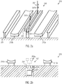
- Figure 2a schematically illustrates a perspective view of a production facility 200 including a transport system 250 that enables a repositioning of an elongated support member 251 with respect to first and second mould assemblies 210a, 210b.
- first and second mould assemblies 210a, 210b are positioned at any appropriate height level above a floor 201 and similarly the support member 251 is positioned at an appropriate height level in order to provide for superior accessibility of the first and second mould assemblies 210a, 210b.
- the transport system 250 comprises a drive mechanism 257 that is configured to lift the support member 251 to any appropriate height so as to enable a non-disturbed movement of the mould assembly 210b, as for instance explained above with reference to figures 1 a and 1 b.
- the drive mechanism 257 may comprise an appropriate actuator, such as a motor, and the like, which is not shown in figure 2a , in combination with two or more appropriately positioned mechanical connections 257a, 257b which enable a vertical movement of the member 251.
- the support member 251 may comprise a guide element 251 a so as to precisely define the working position of the member 251.
- Figure 2b schematically illustrates a cross-sectional view of the facility 200, wherein the drive mechanism 257 is appropriately configured to lower the position of the support member 251 in order to define an appropriate non-interference positioned 202n.
- the drive mechanism 257 may be positioned in a recess 201 r in the floor 201, wherein even a substantially flush configuration may be obtained in the non-interference position 202n.
- the support member 251 may be lifted into the working position 202w or in any other intermediate position.
- Figure 2C schematically illustrates a cross-sectional view of the facility 200, wherein the drive mechanism 257 is configured to move the elongated support member 251 from the working position 202w into the non-interference position 202n and vice versa by initiating a translational movement in the horizontal direction.
- any appropriate components such as a rail system attached to the floor or ceiling of the facility 200 may be provided with appropriately positioned and configured support members (not shown) that in turn are coupled to a drive component, such as a motor, and the like.
- Figure 3a schematically illustrates a cross-sectional view of a production facility 300, in which a transport system 350 is configured so as to enable a rotational movement of a support member 351.
- a drive mechanism 357 is positioned in close proximity or attached to a mould drive mechanism 320 and enables a rotation of the support member 351 between the working position 302w and a non-interference position 302n.
- a second mould assembly 310b is positioned above a first mould assembly 310a, thereby forming the composite mould assembly, as is also discussed above.
- the rotation of the second mould assembly 310b is performed around an axis of rotation 325 that extends along the length direction and thus in parallel with the elongated mould assemblies 310a, 310b.
- the axis of rotation such as the axis 325
- the axis of rotation represents the only axis of rotation for forming the composite mould assembly, while it is to be appreciated, however, that a more complex composite movement may be applied so as to appropriately position the first and second mould assemblies.
- a composite movement of the first and/or the second mould assembly may comprise the patients about to laterally offset axis of rotation, possibly in combination with a translational movement. Irrespective of the complexity of the movement provided by the mould drive mechanism, such as the mechanism 320, the drive mechanism connected to the elongated support member is appropriately configured to position the support member in the non-interference position.
- Figure 3b schematically illustrates the support member 351 in its working position.
- the hinge mechanism 358 is provided, for instance attached to the mould drive mechanism 320.
- Figure 4a schematically illustrates a perspective view of a production facility 400, in which a mould drive mechanism 420 is illustrated in the form of two individual drive components 421 a, 421 b, which in turn are configured to rotate a second mould assembly 410b by an appropriate angle of rotation, for instance by approximately 180° so as to position the mould assembly 410b above a first mould assembly (not shown), as discussed above.
- a transport system 450 comprises a support member 451 with drive components 458a, 458b, which are mechanically coupled to the drive components 421 a, 421 b, respectively. Consequently, upon activating the drive components 421 a, 421 b also a rotational movement of the support member 451 is initiated.
- the drive components 458a, 458b may include a corresponding period system so as to adjust the ratio of the angles of rotation.
- the corresponding gearboxes may result in a reduction of the angle of rotation of approximately 2:1, wherein an angle of rotation of approximately 90° is appropriate for moving the support member 451 into the non-interference position.
- Figure 4b schematically illustrates the support member for 51 when rotated into the working position 402n, which is accomplished by activating the drive components 421 a, 421 b in order to bring the mould assembly into the desired closed position.
- FIG. 5a schematically illustrates a perspective view of a production facility 500, in which a support member 551 is connected to a drive mechanism 557 that comprises a plurality of individual drive components 557a, 557b, 557c that are individually controllable, for instance by means of a control unit 559, with respect to a drive mechanism 520 that comprises a plurality of drive components 521 a, 521 b for rotating a mould assembly 510b into a closed position.
- the support member 551 is movable independently with respect to the mould assembly 510b.
- Figure 5b schematically illustrates the production facility, when the support member 551 has been rotated into the non-interference position 502n in order to allow the subsequent activation of the mould drive assembly 520, thereby bringing the corresponding mould assemblies into the closed position.
- the production facilities 100, 200, 300, 400 and 500 are appropriately configured to move the elongated support member "as a whole", thereby allowing for superior flexibility with respect to providing access to the mould assemblies by workers and operators, while, when moving the elongated support member into its working position, one or both mould assemblies may be accessed by the movable parts of the transport system, which may be used for positioning a robot device, and the like.
- the movement of the elongated support member may be appropriately controlled so as to position the support member at a non-interference position, in which a movement or rotation of the movable mould assembly is accomplished without interference by the support member.
- an appropriate control unit may be provided so as to coordinate the motions of the support member and the movable mould assembly.
- the one or more movable parts of the transport system are positioned in a "parking position", i.e. in the position without contact to the elongated support member, while also movement of the movable mould assembly is initiated only when the support member is positioned in its non-interference position.
- the movements of the mould assembly and the support member are mechanically coupled, thereby automatically ensuring an appropriate coordination of these two movements.
Landscapes
- Engineering & Computer Science (AREA)
- Mechanical Engineering (AREA)
- Robotics (AREA)
- Chemical & Material Sciences (AREA)
- General Engineering & Computer Science (AREA)
- Life Sciences & Earth Sciences (AREA)
- Sustainable Development (AREA)
- Sustainable Energy (AREA)
- Combustion & Propulsion (AREA)
- Composite Materials (AREA)
- Architecture (AREA)
- Wind Motors (AREA)
- Automatic Assembly (AREA)
- Moulding By Coating Moulds (AREA)
Claims (15)
- Produktionsanlage (100; 200; 300; 400; 500), umfassend:eine erste längliche Formanordnung (110a; 210a; 310a),eine zweite längliche Formanordnung (110b; 210b; 310b; 410b; 510b), die sich parallel zu der ersten länglichen Formanordnung (110a; 210a) erstreckt, undein Transportsystem (150; 250; 350; 450; 550), umfassendein längliches Stützelement (151; 251; 351; 451; 551), das sich entlang und lateral zwischen der ersten und zweiten länglichen Formanordnung (110a, 110b; 310a; 210a; 210b; 310b; 410b; 510b) erstreckt,ein bewegliches Teil (155, 156), ausgebildet, um zumindest entlang der ersten und zweiten länglichen Formanordnung (110a, 210a; 310a; 110b; 210b; 310b; 410b; 510b) angeordnet zu werden, unter Verwendung des länglichen Stützelements (151; 251; 351; 451; 551);wobei das längliche Stützelement (151; 251; 351; 451; 551) sich entlang der Längsrichtung L parallel zu der ersten und zweiten länglichen Formanordnung (110a, 110b; 310b; 210a; 210b; 310b; 410b; 510b) erstreckt, und wobei das längliche Stützelement (151; 251; 351; 451; 551) entsprechend ausgebildet ist, um das bewegliche Teil (155, 156) des Transportsystems (150; 250; 350; 450; 550) zu befähigen, entlang des länglichen Stützelements (151; 251; 351; 451; 551) bewegt zu werden; undwobei das längliche Stützelement (151; 251; 351; 451; 551) eine Länge aufweist, die geeignet ist zum Gewähren des Zugangs zu zumindest einem erheblichen Abschnitt der ersten und zweiten länglichen Formanordnung (110a, 110b; 310b; 210a; 210b; 310b; 410b; 510b) durch das bewegliche Teil (155, 156), undeinen Antriebsmechanismus (157; 257; 357; 457; 557), gekoppelt an das längliche Stützelement (151; 251; 351; 451; 551) und ausgebildet zum Verändern einer Position des länglichen Stützelements (151; 251; 351; 451; 551) bezüglich der ersten und zweiten länglichen Formanordnung (110a, 210a; 310b; 110b; 210b; 310b; 410b; 510b),wobei der erhebliche Abschnitt als zumindest die Hälfte der Länge der ersten und zweiten Formanordnung (110a, 110b) verstanden wird.
- Produktionsanlage nach Anspruch 1, weiterhin umfassend einen Formantriebsmechanismus (120; 220; 320; 420; 520) gekoppelt zumindest mit der zweiten länglichen Formanordnung und ausgebildet zu, Positionieren der zweiten länglichen Formanordnung relativ zu der ersten Formanordnung, um eine Verbundformanordnung (111) zu bilden.
- Produktionsanlage nach Anspruch 2, wobei der Antriebsmechanismus (157; 257; 357; 457; 557) ausgebildet ist zum Ausführen einer Veränderung der Position des länglichen Stützelements, um das längliche Stützelement an einer störungsfreien Position (202n) zu positionieren, die Einflussnahme auf das Positionieren der zweiten länglichen Formanordnung relativ zu der ersten Formanordnung vermeidet, um eine Verbundformanordnung zu bilden.
- Produktionsanlage nach einem der Ansprüche 1 bis 3, wobei der Antriebsmechanismus (157; 257) ausgebildet ist zum Ausführen einer Veränderung der Position mittels Einleiten von zumindest Translationsbewegung des länglichen Stützelements.
- Produktionsanlage nach Anspruch 4, wobei die Translationsbewegung eine horizontale Bewegung ist.
- Produktionsanlage nach Anspruch 4, wobei die Translationsbewegung eine vertikale Bewegung ist.
- Produktionsanlage nach Ansprüchen 2 und 6, wobei der Antriebsmechanismus (257a; 257b) ausgebildet ist zum Heben des länglichen Stützelements in die störungsfreie Position.
- Produktionsanlage nach Anspruch 1, wobei der Antriebsmechanismus ausgebildet ist zum Absenken des länglichen Stützelements in die störungsfreie Position (202n).
- Produktionsanlage nach einem der Ansprüche 1 bis 6, wobei der Antriebsmechanismus (157; 357; 458a, 458b; 557, 557a, 557b, 557c) ausgebildet ist zum Ausführen einer Veränderung der Position durch Einleiten von zumindest einer Drehbewegung des länglichen Stützelements entlang einer Drehachse.
- Produktionsanlage nach Ansprüchen 2 und 9, wobei der der Antriebsmechanismus und der Formantriebsmechanismus (420, 421 a, 421 b, 458a, 458b) gekoppelt sind und ausgebildet sind zum Ausführen der Drehbewegung während des Positionierens der zweiten länglichen Formanordnung relativ zu der ersten Formanordnung, um eine Verbundformanordnung zu bilden.
- Verfahren zum Bilden eines länglichen Produktes, insbesondere eines Windturbinenblattes, das Verfahren umfassend:Füllen von Material in eine erste längliche Formanordnung (110a; 210a; 310a) und eine zweite längliche Formanordnung (110b; 210b; 310b; 410b; 510b) unter Verwendung eines beweglichen Teils eines Transportsystems (150; 250; 350; 450; 550), das beweglich ist entlang eines länglichen Stützelements (151; 251; 351; 451; 551) des Transportsystems, das sich entlang der Längsrichtung L parallel zu der ersten und zweiten länglichen Formanordnung (110a, 110b; 310b; 210a; 210b; 310b; 410b; 510b) erstreckt, wobei sich das längliche Stützelement entlang und lateral zwischen der ersten und zweiten länglichen Formanordnung (110a, 110b; 310b; 210a; 210b; 310b; 410b; 510b) erstreckt, und wobei das längliche Stützelement (151; 251; 351; 451; 551) eine Länge aufweist, die geeignet ist zum Gewähren des Zugangs zu zumindest einem erheblichen Abschnitt der ersten und zweiten länglichen Formanordnung (110a, 110b; 310a; 210a; 210b; 310b; 410b; 510b) durch das bewegliche Teil (155, 156), wobei der erhebliche Abschnitt als zumindest die Hälfte der Länge der ersten und zweiten Formanordnung (110a, 110b) verstanden wird,Bilden einer Verbundformanordnung durch drehen zumindest einer der ersten und zweiten Formanordnung und durch Positionieren des länglichen Stützelements (151; 251; 351; 451; 551) in einer störungsfreien Position.
- Verfahren nach Anspruch 11, wobei Positionieren des länglichen Stützelements in einer störungsfreien Position umfasst Ausführen einer Translationsbewegung des länglichen Stützelements.
- Verfahren nach Anspruch 12, wobei die Translationsbewegung eine horizontale Bewegung ist.
- Verfahren nach Anspruch 12, wobei die Translationsbewegung eine vertikale Bewegung ist.
- Verfahren nach einem der Ansprüche 11 bis 14, wobei Positionieren des länglichen Stützelements in einer störungsfreien Position umfasst Ausführen einer Drehbewegung des länglichen Stützelements um eine Drehachse, die entlang einer Längsrichtung der ersten und zweiten länglichen Formanordnung ausgerichtet ist.
Applications Claiming Priority (7)
| Application Number | Priority Date | Filing Date | Title |
|---|---|---|---|
| DKPA201170419 | 2011-07-28 | ||
| DKPA201170418 | 2011-07-28 | ||
| DKPA201170417 | 2011-07-28 | ||
| US201161521367P | 2011-08-08 | 2011-08-08 | |
| US201161521369P | 2011-08-08 | 2011-08-08 | |
| US201161521371P | 2011-08-08 | 2011-08-08 | |
| PCT/DK2012/050272 WO2013013676A1 (en) | 2011-07-28 | 2012-07-19 | A production facility comprising a transport system for processing elongated products, in particular wind turbine blades, with elongated mould assemblies |
Publications (2)
| Publication Number | Publication Date |
|---|---|
| EP2736692A1 EP2736692A1 (de) | 2014-06-04 |
| EP2736692B1 true EP2736692B1 (de) | 2016-12-07 |
Family
ID=47600526
Family Applications (1)
| Application Number | Title | Priority Date | Filing Date |
|---|---|---|---|
| EP12746010.3A Active EP2736692B1 (de) | 2011-07-28 | 2012-07-19 | Produktionsanlage mit einem transportsystem zur verarbeitung von länglichen produkten, insbesondere windturbinenschaufeln, mit verlängerten formkörperanordnungen |
Country Status (5)
| Country | Link |
|---|---|
| US (1) | US9689266B2 (de) |
| EP (1) | EP2736692B1 (de) |
| DK (1) | DK2736692T3 (de) |
| ES (1) | ES2613639T3 (de) |
| WO (1) | WO2013013676A1 (de) |
Families Citing this family (10)
| Publication number | Priority date | Publication date | Assignee | Title |
|---|---|---|---|---|
| CN102019694A (zh) * | 2009-09-23 | 2011-04-20 | 苏州红枫风电模具有限公司 | 风轮机叶片自动生产系统 |
| WO2013060336A1 (en) * | 2011-10-27 | 2013-05-02 | Vestas Wind Systems A/S | A production apparatus and a method for manufacturing elongated products such as wind turbine blades |
| US10011080B2 (en) * | 2014-09-29 | 2018-07-03 | The Boeing Company | Composite part forming system |
| US10035300B2 (en) * | 2015-06-23 | 2018-07-31 | The Boeing Company | System and method for manufacturing a stiffened composite structure |
| ES2949268T3 (es) * | 2019-05-28 | 2023-09-27 | Siemens Gamesa Renewable Energy As | Un molde para fabricar una pala de turbina eólica y un método para fabricar una pala de turbina eólica |
| GB201907911D0 (en) | 2019-06-04 | 2019-07-17 | Blade Dynamics Ltd | Wind turbine blade tool and method for producing a wind turbine blade |
| GB202007798D0 (en) * | 2020-05-26 | 2020-07-08 | Lm Wind Power As | System for manufacturing a composite structure |
| CN113550868B (zh) * | 2021-09-06 | 2022-10-21 | 秦皇岛舒克智控科技有限公司 | 一种辅助风力发电叶片快速装车装置 |
| DE102023121542A1 (de) | 2023-08-11 | 2025-02-13 | Thyssenkrupp Steel Europe Ag | Maßgeschneidertes Halbzeug und äußere Seitenwandverstärkung |
| DE102024100229A1 (de) | 2024-01-04 | 2025-07-10 | Thyssenkrupp Steel Europe Ag | Maßgeschneidertes Halbzeug und Seitenwandverstärkung |
Family Cites Families (30)
| Publication number | Priority date | Publication date | Assignee | Title |
|---|---|---|---|---|
| GB191400597A (en) * | 1913-07-29 | 1914-08-07 | Friedrich Wilhelm Heuser | Equipment for Producing Welded Seams by Means of the Electric Arc and Added Welding Material. |
| CH438627A (de) * | 1964-03-03 | 1967-06-30 | Poroli Vincenzo | Bockkran mit aus Mastschüssen aufstockbaren Stützmasten |
| GB1121251A (en) * | 1965-01-09 | 1968-07-24 | Anderston Clyde Engineers Ltd | Mobile gantry crane |
| US4139180A (en) * | 1976-03-18 | 1979-02-13 | Mitsui Engineering & Shipbuilding Co., Ltd. | Apparatus for breaking up large construction |
| US4098624A (en) * | 1976-12-28 | 1978-07-04 | Upton Industries, Inc. | Process for increasing the versatility of isothermal transformation |
| US4334480A (en) * | 1978-09-22 | 1982-06-15 | Wallace Bernard E | Gantries |
| US4381839A (en) * | 1981-03-02 | 1983-05-03 | Riggers Manufacturing Co. | Gantry having adjustable side supports |
| US4619427A (en) * | 1984-06-29 | 1986-10-28 | Heinrich Oelschlager Metallwarenfabrik | Stand for data display terminals |
| DE3623506A1 (de) * | 1986-07-09 | 1988-01-28 | Mannesmann Ag | Fuehrung fuer einen industrieroboter |
| US4966323A (en) * | 1987-12-02 | 1990-10-30 | Gemcor Engineering Corp. | Five axis riveter and system |
| EP0455371A3 (en) * | 1990-04-24 | 1992-04-22 | Engineering Incorporated | Robotic carrier mechanism for aircraft maintenance |
| US5359542A (en) * | 1991-12-20 | 1994-10-25 | The Boeing Company | Variable parameter collision avoidance system for aircraft work platforms |
| US5360123A (en) * | 1993-03-05 | 1994-11-01 | J&R Engineering Company, Inc. | Gantry stabilizer |
| US5351809A (en) * | 1993-04-26 | 1994-10-04 | Rapistan Demag Corporation | Multiple-stage extendable conveyor |
| US5896637A (en) * | 1996-09-25 | 1999-04-27 | Mcdonnell Douglas Corporation | Assembly tower |
| JP2001293643A (ja) * | 2000-04-17 | 2001-10-23 | Hirata Corp | 生産システム |
| US20030161708A1 (en) * | 2002-02-22 | 2003-08-28 | Johnston Roger L. | Triangulated mobile gantry crane |
| DK200201743A (da) | 2002-11-12 | 2004-05-13 | Lm Glasfiber As | Formindretning med lukkemekanisme |
| AT412966B (de) * | 2003-01-27 | 2005-09-26 | Hubert Anton Kaufmann | Transporteinrichtung, insbesondere für plattenförmige werkstücke |
| CA2440788C (en) * | 2003-09-12 | 2012-01-03 | Jean-Paul Fredette | Motorized scaffold with displaceable worker support platform |
| DE102004040161B4 (de) * | 2004-08-19 | 2010-01-28 | Eisenmann Anlagenbau Gmbh & Co. Kg | Vorrichtung zum Beschichten von Gegenständen |
| DK200501539A (da) * | 2005-11-08 | 2007-05-09 | Lm Glasfiber As | Formindretning med hængselmekanisme og fremgangsmåde til lukning af en formindretning |
| US7730622B2 (en) * | 2006-08-02 | 2010-06-08 | Mccauley Kerry | Structural surface measuring and aligning apparatus and method |
| WO2008107200A1 (en) * | 2007-03-07 | 2008-09-12 | Powerscreen International Distribution Limited | Foldable framework for auxiliary conveyor |
| CA2708135C (en) * | 2007-12-11 | 2015-11-03 | John Bremhorst | Conveyor belt support apparatus having sequentially extendable frame segments |
| EP2427311A2 (de) | 2009-05-04 | 2012-03-14 | Mag Ias Llc. | Anwendung zur schnellen materialplatzierung zur herstellung von windturbinenschaufeln |
| ES2365571B1 (es) | 2009-05-21 | 2012-09-17 | Danobat S.Coop | Sistema para la fabricacion automatica de palas de aerogenerador |
| CN102019694A (zh) | 2009-09-23 | 2011-04-20 | 苏州红枫风电模具有限公司 | 风轮机叶片自动生产系统 |
| JP5477651B2 (ja) * | 2010-08-04 | 2014-04-23 | 株式会社ダイフク | 物品搬送設備 |
| WO2012019610A1 (en) * | 2010-08-11 | 2012-02-16 | Vestas Wind Systems A/S | Apparatus for fabricating a wind turbine blade and related method |
-
2012
- 2012-07-19 EP EP12746010.3A patent/EP2736692B1/de active Active
- 2012-07-19 DK DK12746010.3T patent/DK2736692T3/en active
- 2012-07-19 WO PCT/DK2012/050272 patent/WO2013013676A1/en not_active Ceased
- 2012-07-19 ES ES12746010.3T patent/ES2613639T3/es active Active
- 2012-07-19 US US14/235,390 patent/US9689266B2/en active Active
Also Published As
| Publication number | Publication date |
|---|---|
| US9689266B2 (en) | 2017-06-27 |
| ES2613639T3 (es) | 2017-05-25 |
| WO2013013676A1 (en) | 2013-01-31 |
| US20140215783A1 (en) | 2014-08-07 |
| DK2736692T3 (en) | 2017-01-30 |
| EP2736692A1 (de) | 2014-06-04 |
Similar Documents
| Publication | Publication Date | Title |
|---|---|---|
| DK2736692T3 (en) | Production plant comprising a transport system for processing extended products, especially wind turbine blades, with extended mold assemblies | |
| EP1963068B1 (de) | Formwerkzeuganordnung mit scharniermechanismus und verfahren zum schliessen der formwerkzeuganordnung | |
| US20120205048A1 (en) | Wind turbine blade automated production system | |
| EP3023237B1 (de) | Verfahren und Vorrichtung zur Herstellung eines dreidimensionalen Objekts mittels Additivherstellung | |
| US8296923B2 (en) | Modular numerically controlled system | |
| EP1562733B1 (de) | Formwerkzeuganordnung mit schliessmechanismus | |
| ES2513017T3 (es) | Sistema de colocación de material compuesto pequeño y plano | |
| JP4376968B2 (ja) | ポリマーと複合物の成品の製造のための方法と設備 | |
| US9375907B2 (en) | Production system for producing fibre composite material components | |
| CN107000329B (zh) | 使制造风力涡轮机叶片部件的第一模具部件相对于第二模具部件翻转的翻转装置 | |
| EP3119589A1 (de) | Verfahren und vorrichtung zur herstellung eines objekts | |
| WO2005105415A2 (en) | Forming a composite structure by filament placement on a tool surface of a tablet | |
| US20010020518A1 (en) | Oscillating arm apparatus for manufacturing a tire reinforcement from a single cord | |
| EP2941342A1 (de) | Verfahren und vorrichtung zur herstellung profilierter laminatstrukturen | |
| US12070878B2 (en) | Modular molding units for fabrication of wind turbine blades | |
| US12077319B2 (en) | Fabrication line, systems, and methods for fuselage sections | |
| CN115094575A (zh) | 一种混合切换双工位针刺机器人 | |
| US20140300027A1 (en) | Systems and methods for applying a braid to an irregular core | |
| RU2637679C2 (ru) | Способ изготовления роторной лопасти | |
| EP4326540A1 (de) | Verfahren zur herstellung einer windturbinenschaufelkomponente und windturbinenschaufelfuss | |
| CN114536812A (zh) | 用于移动生产线中的复合部件的区域层压 | |
| CN120418069A (zh) | 铺层系统 | |
| CN201534381U (zh) | 风轮机叶片自动生产系统 | |
| ES2986732T3 (es) | Desmoldeo de grandes piezas de material compuesto para aeronaves | |
| EP4000847B1 (de) | Fertigungssysteme für rumpfabschnitte |
Legal Events
| Date | Code | Title | Description |
|---|---|---|---|
| PUAI | Public reference made under article 153(3) epc to a published international application that has entered the european phase |
Free format text: ORIGINAL CODE: 0009012 |
|
| 17P | Request for examination filed |
Effective date: 20140206 |
|
| AK | Designated contracting states |
Kind code of ref document: A1 Designated state(s): AL AT BE BG CH CY CZ DE DK EE ES FI FR GB GR HR HU IE IS IT LI LT LU LV MC MK MT NL NO PL PT RO RS SE SI SK SM TR |
|
| DAX | Request for extension of the european patent (deleted) | ||
| RAP1 | Party data changed (applicant data changed or rights of an application transferred) |
Owner name: VESTAS WIND SYSTEMS A/S |
|
| 17Q | First examination report despatched |
Effective date: 20150520 |
|
| GRAP | Despatch of communication of intention to grant a patent |
Free format text: ORIGINAL CODE: EPIDOSNIGR1 |
|
| INTG | Intention to grant announced |
Effective date: 20160629 |
|
| GRAS | Grant fee paid |
Free format text: ORIGINAL CODE: EPIDOSNIGR3 |
|
| GRAA | (expected) grant |
Free format text: ORIGINAL CODE: 0009210 |
|
| AK | Designated contracting states |
Kind code of ref document: B1 Designated state(s): AL AT BE BG CH CY CZ DE DK EE ES FI FR GB GR HR HU IE IS IT LI LT LU LV MC MK MT NL NO PL PT RO RS SE SI SK SM TR |
|
| REG | Reference to a national code |
Ref country code: GB Ref legal event code: FG4D |
|
| REG | Reference to a national code |
Ref country code: CH Ref legal event code: EP Ref country code: AT Ref legal event code: REF Ref document number: 851321 Country of ref document: AT Kind code of ref document: T Effective date: 20161215 |
|
| REG | Reference to a national code |
Ref country code: IE Ref legal event code: FG4D |
|
| REG | Reference to a national code |
Ref country code: DE Ref legal event code: R096 Ref document number: 602012026295 Country of ref document: DE |
|
| REG | Reference to a national code |
Ref country code: DK Ref legal event code: T3 Effective date: 20170126 |
|
| PG25 | Lapsed in a contracting state [announced via postgrant information from national office to epo] |
Ref country code: LV Free format text: LAPSE BECAUSE OF FAILURE TO SUBMIT A TRANSLATION OF THE DESCRIPTION OR TO PAY THE FEE WITHIN THE PRESCRIBED TIME-LIMIT Effective date: 20161207 |
|
| REG | Reference to a national code |
Ref country code: LT Ref legal event code: MG4D |
|
| REG | Reference to a national code |
Ref country code: NL Ref legal event code: MP Effective date: 20161207 |
|
| PG25 | Lapsed in a contracting state [announced via postgrant information from national office to epo] |
Ref country code: GR Free format text: LAPSE BECAUSE OF FAILURE TO SUBMIT A TRANSLATION OF THE DESCRIPTION OR TO PAY THE FEE WITHIN THE PRESCRIBED TIME-LIMIT Effective date: 20170308 Ref country code: NO Free format text: LAPSE BECAUSE OF FAILURE TO SUBMIT A TRANSLATION OF THE DESCRIPTION OR TO PAY THE FEE WITHIN THE PRESCRIBED TIME-LIMIT Effective date: 20170307 Ref country code: LT Free format text: LAPSE BECAUSE OF FAILURE TO SUBMIT A TRANSLATION OF THE DESCRIPTION OR TO PAY THE FEE WITHIN THE PRESCRIBED TIME-LIMIT Effective date: 20161207 Ref country code: SE Free format text: LAPSE BECAUSE OF FAILURE TO SUBMIT A TRANSLATION OF THE DESCRIPTION OR TO PAY THE FEE WITHIN THE PRESCRIBED TIME-LIMIT Effective date: 20161207 |
|
| REG | Reference to a national code |
Ref country code: AT Ref legal event code: MK05 Ref document number: 851321 Country of ref document: AT Kind code of ref document: T Effective date: 20161207 |
|
| REG | Reference to a national code |
Ref country code: ES Ref legal event code: FG2A Ref document number: 2613639 Country of ref document: ES Kind code of ref document: T3 Effective date: 20170525 |
|
| PG25 | Lapsed in a contracting state [announced via postgrant information from national office to epo] |
Ref country code: RS Free format text: LAPSE BECAUSE OF FAILURE TO SUBMIT A TRANSLATION OF THE DESCRIPTION OR TO PAY THE FEE WITHIN THE PRESCRIBED TIME-LIMIT Effective date: 20161207 Ref country code: HR Free format text: LAPSE BECAUSE OF FAILURE TO SUBMIT A TRANSLATION OF THE DESCRIPTION OR TO PAY THE FEE WITHIN THE PRESCRIBED TIME-LIMIT Effective date: 20161207 Ref country code: FI Free format text: LAPSE BECAUSE OF FAILURE TO SUBMIT A TRANSLATION OF THE DESCRIPTION OR TO PAY THE FEE WITHIN THE PRESCRIBED TIME-LIMIT Effective date: 20161207 |
|
| PG25 | Lapsed in a contracting state [announced via postgrant information from national office to epo] |
Ref country code: NL Free format text: LAPSE BECAUSE OF FAILURE TO SUBMIT A TRANSLATION OF THE DESCRIPTION OR TO PAY THE FEE WITHIN THE PRESCRIBED TIME-LIMIT Effective date: 20161207 |
|
| PG25 | Lapsed in a contracting state [announced via postgrant information from national office to epo] |
Ref country code: SK Free format text: LAPSE BECAUSE OF FAILURE TO SUBMIT A TRANSLATION OF THE DESCRIPTION OR TO PAY THE FEE WITHIN THE PRESCRIBED TIME-LIMIT Effective date: 20161207 Ref country code: CZ Free format text: LAPSE BECAUSE OF FAILURE TO SUBMIT A TRANSLATION OF THE DESCRIPTION OR TO PAY THE FEE WITHIN THE PRESCRIBED TIME-LIMIT Effective date: 20161207 Ref country code: EE Free format text: LAPSE BECAUSE OF FAILURE TO SUBMIT A TRANSLATION OF THE DESCRIPTION OR TO PAY THE FEE WITHIN THE PRESCRIBED TIME-LIMIT Effective date: 20161207 Ref country code: RO Free format text: LAPSE BECAUSE OF FAILURE TO SUBMIT A TRANSLATION OF THE DESCRIPTION OR TO PAY THE FEE WITHIN THE PRESCRIBED TIME-LIMIT Effective date: 20161207 Ref country code: IS Free format text: LAPSE BECAUSE OF FAILURE TO SUBMIT A TRANSLATION OF THE DESCRIPTION OR TO PAY THE FEE WITHIN THE PRESCRIBED TIME-LIMIT Effective date: 20170407 |
|
| PG25 | Lapsed in a contracting state [announced via postgrant information from national office to epo] |
Ref country code: SM Free format text: LAPSE BECAUSE OF FAILURE TO SUBMIT A TRANSLATION OF THE DESCRIPTION OR TO PAY THE FEE WITHIN THE PRESCRIBED TIME-LIMIT Effective date: 20161207 Ref country code: BE Free format text: LAPSE BECAUSE OF FAILURE TO SUBMIT A TRANSLATION OF THE DESCRIPTION OR TO PAY THE FEE WITHIN THE PRESCRIBED TIME-LIMIT Effective date: 20161207 Ref country code: PL Free format text: LAPSE BECAUSE OF FAILURE TO SUBMIT A TRANSLATION OF THE DESCRIPTION OR TO PAY THE FEE WITHIN THE PRESCRIBED TIME-LIMIT Effective date: 20161207 Ref country code: PT Free format text: LAPSE BECAUSE OF FAILURE TO SUBMIT A TRANSLATION OF THE DESCRIPTION OR TO PAY THE FEE WITHIN THE PRESCRIBED TIME-LIMIT Effective date: 20170407 Ref country code: AT Free format text: LAPSE BECAUSE OF FAILURE TO SUBMIT A TRANSLATION OF THE DESCRIPTION OR TO PAY THE FEE WITHIN THE PRESCRIBED TIME-LIMIT Effective date: 20161207 Ref country code: BG Free format text: LAPSE BECAUSE OF FAILURE TO SUBMIT A TRANSLATION OF THE DESCRIPTION OR TO PAY THE FEE WITHIN THE PRESCRIBED TIME-LIMIT Effective date: 20170307 |
|
| REG | Reference to a national code |
Ref country code: DE Ref legal event code: R097 Ref document number: 602012026295 Country of ref document: DE |
|
| PLBE | No opposition filed within time limit |
Free format text: ORIGINAL CODE: 0009261 |
|
| STAA | Information on the status of an ep patent application or granted ep patent |
Free format text: STATUS: NO OPPOSITION FILED WITHIN TIME LIMIT |
|
| 26N | No opposition filed |
Effective date: 20170908 |
|
| PG25 | Lapsed in a contracting state [announced via postgrant information from national office to epo] |
Ref country code: SI Free format text: LAPSE BECAUSE OF FAILURE TO SUBMIT A TRANSLATION OF THE DESCRIPTION OR TO PAY THE FEE WITHIN THE PRESCRIBED TIME-LIMIT Effective date: 20161207 |
|
| REG | Reference to a national code |
Ref country code: CH Ref legal event code: PL |
|
| REG | Reference to a national code |
Ref country code: IE Ref legal event code: MM4A |
|
| REG | Reference to a national code |
Ref country code: FR Ref legal event code: ST Effective date: 20180330 |
|
| PG25 | Lapsed in a contracting state [announced via postgrant information from national office to epo] |
Ref country code: LI Free format text: LAPSE BECAUSE OF NON-PAYMENT OF DUE FEES Effective date: 20170731 Ref country code: CH Free format text: LAPSE BECAUSE OF NON-PAYMENT OF DUE FEES Effective date: 20170731 Ref country code: IE Free format text: LAPSE BECAUSE OF NON-PAYMENT OF DUE FEES Effective date: 20170719 |
|
| PG25 | Lapsed in a contracting state [announced via postgrant information from national office to epo] |
Ref country code: FR Free format text: LAPSE BECAUSE OF NON-PAYMENT OF DUE FEES Effective date: 20170731 |
|
| PG25 | Lapsed in a contracting state [announced via postgrant information from national office to epo] |
Ref country code: LU Free format text: LAPSE BECAUSE OF NON-PAYMENT OF DUE FEES Effective date: 20170719 |
|
| PG25 | Lapsed in a contracting state [announced via postgrant information from national office to epo] |
Ref country code: MT Free format text: LAPSE BECAUSE OF NON-PAYMENT OF DUE FEES Effective date: 20170719 |
|
| PG25 | Lapsed in a contracting state [announced via postgrant information from national office to epo] |
Ref country code: MC Free format text: LAPSE BECAUSE OF FAILURE TO SUBMIT A TRANSLATION OF THE DESCRIPTION OR TO PAY THE FEE WITHIN THE PRESCRIBED TIME-LIMIT Effective date: 20161207 Ref country code: HU Free format text: LAPSE BECAUSE OF FAILURE TO SUBMIT A TRANSLATION OF THE DESCRIPTION OR TO PAY THE FEE WITHIN THE PRESCRIBED TIME-LIMIT; INVALID AB INITIO Effective date: 20120719 |
|
| PG25 | Lapsed in a contracting state [announced via postgrant information from national office to epo] |
Ref country code: CY Free format text: LAPSE BECAUSE OF NON-PAYMENT OF DUE FEES Effective date: 20161207 |
|
| PG25 | Lapsed in a contracting state [announced via postgrant information from national office to epo] |
Ref country code: MK Free format text: LAPSE BECAUSE OF FAILURE TO SUBMIT A TRANSLATION OF THE DESCRIPTION OR TO PAY THE FEE WITHIN THE PRESCRIBED TIME-LIMIT Effective date: 20161207 |
|
| PG25 | Lapsed in a contracting state [announced via postgrant information from national office to epo] |
Ref country code: TR Free format text: LAPSE BECAUSE OF FAILURE TO SUBMIT A TRANSLATION OF THE DESCRIPTION OR TO PAY THE FEE WITHIN THE PRESCRIBED TIME-LIMIT Effective date: 20161207 |
|
| PG25 | Lapsed in a contracting state [announced via postgrant information from national office to epo] |
Ref country code: AL Free format text: LAPSE BECAUSE OF FAILURE TO SUBMIT A TRANSLATION OF THE DESCRIPTION OR TO PAY THE FEE WITHIN THE PRESCRIBED TIME-LIMIT Effective date: 20161207 |
|
| P01 | Opt-out of the competence of the unified patent court (upc) registered |
Effective date: 20230521 |
|
| PGFP | Annual fee paid to national office [announced via postgrant information from national office to epo] |
Ref country code: DE Payment date: 20240730 Year of fee payment: 13 |
|
| PGFP | Annual fee paid to national office [announced via postgrant information from national office to epo] |
Ref country code: DK Payment date: 20240725 Year of fee payment: 13 |
|
| PGFP | Annual fee paid to national office [announced via postgrant information from national office to epo] |
Ref country code: GB Payment date: 20240724 Year of fee payment: 13 |
|
| PGFP | Annual fee paid to national office [announced via postgrant information from national office to epo] |
Ref country code: ES Payment date: 20240806 Year of fee payment: 13 |
|
| PGFP | Annual fee paid to national office [announced via postgrant information from national office to epo] |
Ref country code: IT Payment date: 20240722 Year of fee payment: 13 |
|
| REG | Reference to a national code |
Ref country code: DE Ref legal event code: R119 Ref document number: 602012026295 Country of ref document: DE |
|
| REG | Reference to a national code |
Ref country code: DK Ref legal event code: EBP Effective date: 20250731 |
|
| GBPC | Gb: european patent ceased through non-payment of renewal fee |
Effective date: 20250719 |
|
| PG25 | Lapsed in a contracting state [announced via postgrant information from national office to epo] |
Ref country code: GB Free format text: LAPSE BECAUSE OF NON-PAYMENT OF DUE FEES Effective date: 20250719 |
|
| PG25 | Lapsed in a contracting state [announced via postgrant information from national office to epo] |
Ref country code: DE Free format text: LAPSE BECAUSE OF NON-PAYMENT OF DUE FEES Effective date: 20260203 |