EP2736664B1 - Adjustable cutting tool - Google Patents
Adjustable cutting tool Download PDFInfo
- Publication number
- EP2736664B1 EP2736664B1 EP12750824.0A EP12750824A EP2736664B1 EP 2736664 B1 EP2736664 B1 EP 2736664B1 EP 12750824 A EP12750824 A EP 12750824A EP 2736664 B1 EP2736664 B1 EP 2736664B1
- Authority
- EP
- European Patent Office
- Prior art keywords
- cutting
- insert
- adjustment member
- axis
- tool
- Prior art date
- Legal status (The legal status is an assumption and is not a legal conclusion. Google has not performed a legal analysis and makes no representation as to the accuracy of the status listed.)
- Not-in-force
Links
Images


Classifications
-
- B—PERFORMING OPERATIONS; TRANSPORTING
- B23—MACHINE TOOLS; METAL-WORKING NOT OTHERWISE PROVIDED FOR
- B23B—TURNING; BORING
- B23B27/00—Tools for turning or boring machines; Tools of a similar kind in general; Accessories therefor
- B23B27/06—Profile cutting tools, i.e. forming-tools
- B23B27/065—Thread-turning tools
-
- B—PERFORMING OPERATIONS; TRANSPORTING
- B23—MACHINE TOOLS; METAL-WORKING NOT OTHERWISE PROVIDED FOR
- B23B—TURNING; BORING
- B23B27/00—Tools for turning or boring machines; Tools of a similar kind in general; Accessories therefor
- B23B27/14—Cutting tools of which the bits or tips or cutting inserts are of special material
- B23B27/16—Cutting tools of which the bits or tips or cutting inserts are of special material with exchangeable cutting bits or cutting inserts, e.g. able to be clamped
- B23B27/1681—Adjustable position of the plate-like cutting inserts
-
- B—PERFORMING OPERATIONS; TRANSPORTING
- B23—MACHINE TOOLS; METAL-WORKING NOT OTHERWISE PROVIDED FOR
- B23B—TURNING; BORING
- B23B27/00—Tools for turning or boring machines; Tools of a similar kind in general; Accessories therefor
- B23B27/14—Cutting tools of which the bits or tips or cutting inserts are of special material
- B23B27/16—Cutting tools of which the bits or tips or cutting inserts are of special material with exchangeable cutting bits or cutting inserts, e.g. able to be clamped
- B23B27/1685—Adjustable position of the cutting inserts
- B23B27/1692—Angular position of the cutting insert adjustable around an axis parallel to the chip-forming plane
-
- B—PERFORMING OPERATIONS; TRANSPORTING
- B23—MACHINE TOOLS; METAL-WORKING NOT OTHERWISE PROVIDED FOR
- B23B—TURNING; BORING
- B23B29/00—Holders for non-rotary cutting tools; Boring bars or boring heads; Accessories for tool holders
- B23B29/04—Tool holders for a single cutting tool
-
- B—PERFORMING OPERATIONS; TRANSPORTING
- B23—MACHINE TOOLS; METAL-WORKING NOT OTHERWISE PROVIDED FOR
- B23B—TURNING; BORING
- B23B29/00—Holders for non-rotary cutting tools; Boring bars or boring heads; Accessories for tool holders
- B23B29/04—Tool holders for a single cutting tool
- B23B29/043—Tool holders for a single cutting tool with cutting-off, grooving or profile cutting tools, i.e. blade- or disc-like main cutting parts
-
- B—PERFORMING OPERATIONS; TRANSPORTING
- B23—MACHINE TOOLS; METAL-WORKING NOT OTHERWISE PROVIDED FOR
- B23B—TURNING; BORING
- B23B29/00—Holders for non-rotary cutting tools; Boring bars or boring heads; Accessories for tool holders
- B23B29/04—Tool holders for a single cutting tool
- B23B29/12—Special arrangements on tool holders
- B23B29/22—Special arrangements on tool holders for tool adjustment by means of shims or spacers
-
- B—PERFORMING OPERATIONS; TRANSPORTING
- B23—MACHINE TOOLS; METAL-WORKING NOT OTHERWISE PROVIDED FOR
- B23B—TURNING; BORING
- B23B2200/00—Details of cutting inserts
- B23B2200/16—Supporting or bottom surfaces
- B23B2200/161—Supporting or bottom surfaces with projections
-
- B—PERFORMING OPERATIONS; TRANSPORTING
- B23—MACHINE TOOLS; METAL-WORKING NOT OTHERWISE PROVIDED FOR
- B23B—TURNING; BORING
- B23B2200/00—Details of cutting inserts
- B23B2200/28—Angles
-
- B—PERFORMING OPERATIONS; TRANSPORTING
- B23—MACHINE TOOLS; METAL-WORKING NOT OTHERWISE PROVIDED FOR
- B23B—TURNING; BORING
- B23B2205/00—Fixation of cutting inserts in holders
- B23B2205/16—Shims
-
- B—PERFORMING OPERATIONS; TRANSPORTING
- B23—MACHINE TOOLS; METAL-WORKING NOT OTHERWISE PROVIDED FOR
- B23B—TURNING; BORING
- B23B2260/00—Details of constructional elements
- B23B2260/004—Adjustable elements
-
- B—PERFORMING OPERATIONS; TRANSPORTING
- B23—MACHINE TOOLS; METAL-WORKING NOT OTHERWISE PROVIDED FOR
- B23C—MILLING
- B23C5/00—Milling-cutters
- B23C5/16—Milling-cutters characterised by physical features other than shape
- B23C5/20—Milling-cutters characterised by physical features other than shape with removable cutter bits or teeth or cutting inserts
- B23C5/22—Securing arrangements for bits or teeth or cutting inserts
- B23C5/24—Securing arrangements for bits or teeth or cutting inserts adjustable
- B23C5/2479—Securing arrangements for bits or teeth or cutting inserts adjustable the adjusting means being eccentrics
-
- Y—GENERAL TAGGING OF NEW TECHNOLOGICAL DEVELOPMENTS; GENERAL TAGGING OF CROSS-SECTIONAL TECHNOLOGIES SPANNING OVER SEVERAL SECTIONS OF THE IPC; TECHNICAL SUBJECTS COVERED BY FORMER USPC CROSS-REFERENCE ART COLLECTIONS [XRACs] AND DIGESTS
- Y10—TECHNICAL SUBJECTS COVERED BY FORMER USPC
- Y10T—TECHNICAL SUBJECTS COVERED BY FORMER US CLASSIFICATION
- Y10T29/00—Metal working
- Y10T29/49—Method of mechanical manufacture
-
- Y—GENERAL TAGGING OF NEW TECHNOLOGICAL DEVELOPMENTS; GENERAL TAGGING OF CROSS-SECTIONAL TECHNOLOGIES SPANNING OVER SEVERAL SECTIONS OF THE IPC; TECHNICAL SUBJECTS COVERED BY FORMER USPC CROSS-REFERENCE ART COLLECTIONS [XRACs] AND DIGESTS
- Y10—TECHNICAL SUBJECTS COVERED BY FORMER USPC
- Y10T—TECHNICAL SUBJECTS COVERED BY FORMER US CLASSIFICATION
- Y10T407/00—Cutters, for shaping
- Y10T407/22—Cutters, for shaping including holder having seat for inserted tool
- Y10T407/2222—Tool adjustable relative to holder
- Y10T407/2224—Tool adjustable relative to holder with indicator
Definitions
- the present invention relates to an adjustable cutting tool for use in metal cutting processes in general, and for threading operations in particular.
- exchangeable anvils or shims directly supporting a removably securable threading insert have long since provided a way to adjust the inclination angle of the threading insert to equal the helix angle of the thread being cut, and thus provide equal clearance for the cutting edges.
- US 3,520,042 discloses an adjustable holder for a thread cutting insert which eliminates the need for exchangeable anvils or shims.
- the adjustable holder comprises a shank with a recess in the form of a partial cone, and a mating partially conical block disposed in the recess.
- the thread cutting insert is mounted on the conical block by means of a set screw, and the conical block is angularly adjustable within the recess so as to provide alignment between the plane of symmetry of the cutting insert and the helix angle of the thread being cut.
- a slot in the shank is angularly aligned with a radial threaded bore in the conical block, and a bolt located in the slot engages the threaded bore to clamp the conical block in the recess at its adjusted position.
- US 2008/0253847 discloses a tool holder assembly which incorporates a cutting edge adjustment member that does not contact the cutting insert.
- the tool holder assembly also includes a tool holder and an insert holder, with the cutting insert being mounted in the insert holder by a screw and a clamp, and an outside curved surface of the insert holder configured to mate with a curved arcuate surface of an insert receiving end of the tool holder.
- the cutting edge adjustment member is in the form a precision ground adjustment washer having an angled top surface.
- An adjustment bolt having a head that rests on the angled top surface of the adjustment washer, protrudes through a slot in the insert receiving end and engages a threaded hole in the insert holder.
- the angle of the top surface determines the rotational position in the slot at which the bolt engages the threaded hole and thus defines a particular cutting edge angle.
- the adjustment washer can be re-oriented or exchanged for another adjustment washer with different angle of top surface to define a different cutting edge angle.
- the cutting tool 20 , 120 includes a cutting insert 22 , a tool holder 24 , and an adjustment member 26, 126 .
- the cutting insert 22 has at least one cutting portion 28 and may be manufactured by form pressing and sintering a cemented carbide, such as tungsten carbide, and may be coated or uncoated.
- a cemented carbide such as tungsten carbide
- the tool holder 24 which may be manufactured from hardened steel, has an insert holder portion 30 , 130 and a shank portion 32 , the insert holder portion 30 , 130 being rigidly fixed to the shank portion 32 .
- the adjustment member 26 , 126 having a first axis A1 , is non-threadingly retained on the insert holder portion 30 , 130 and operatively connected to the cutting insert 22 .
- the adjustment member 26 , 126 may be a non-threaded component.
- the cutting insert 22 is removably secured to the insert holder portion 30 , 130 by means of a fastener 34 , at a cutting position in which the operative cutting portion 28 encounters a workpiece 36 at an insert cutting angle ⁇ .
- the cutting insert 22 may be an indexable threading insert with a plurality of cutting portions 28 , each cutting portion 28 having two cutting edges 38 , 40 , and the cutting tool 20 , 120 may be used in threading operations.
- the insert cutting angle ⁇ is the inclination angle of the two cutting edges 38 , 40 of the operative cutting portion 28 relative to a central axis C of the rotating workpiece 36 .
- the inclination angle of a threading insert is a well known term used in the field of threading operations and typically adjusted to equal the helix angle of the thread being cut, in order to provide equal clearance for both cutting edges.
- Actuation of the adjustment member 26 , 126 causes an increase or decrease of the insert cutting angle ⁇ .
- actuation describes the act of initiating movement of the adjustment member 26, 126 in a predetermined direction or along a predetermined path.
- the cutting tool 20 , 120 may have a single adjustment member 26, 126 .
- actuation of the adjustment member 26, 126 may be performed without removing any components from the cutting tool 20, 120 .
- a method of increasing or decreasing the insert cutting angle ⁇ of the cutting tool 20 , 120 comprises the steps of:
- actuation of the adjustment member 26 , 126 may be performed by rotating the adjustment member 26 , 126 about its first axis A1 .
- the insert cutting angle ⁇ may be increased by rotating the adjustment member 26 , 126 in one direction about its first axis A1 and decreased by rotating the adjustment member 26, 126 in an opposite direction about its first axis A1 .
- the insert holder portion 30 , 130 may have a second axis A2 , and the first axis A1 may be coaxial with the second axis A2 . It can also be understood that the first and second axes A1 , A2 may be coaxial for each rotational position of the adjustment member 26 , 126 , and for each value of the insert cutting angle ⁇ .
- the adjustment member 26 , 126 may be in a fixed translational position on the insert holder portion 30 , 130 , and actuation of the adjustment member 26 , 126 may be performed solely by rotating the adjustment member 26, 126 about its first axis A1 .
- the adjustment member 26, 126 may have a planar base surface 42 , 142 perpendicular to the first axis A1 , and the planar base surface 42 , 142 may be in contact with a corresponding seat surface 44 , 144 on the insert holder portion 30 , 130 .
- the adjustment member 26 , 126 may directly engage the cutting insert 22 .
- the adjustment member 26, 126 may have a top surface 46 , 146 opposing the base surface 42 , 142 , and a side surface 48 , 148 extending therebetween, with the top or side surface 46 , 148 including an adjustment supporting surface 50 , 150 .
- the cutting insert 22 may be a lay-down threading insert having opposing upper and lower surfaces 52 , 54 and a peripheral surface 56 extending therebetween, with the two cutting edges 38 , 40 of each cutting portion 28 having an associated rake surface 58 on the upper or lower surface 52 , 54 .
- the fastener 34 may be in the form of a clamping screw 60 .
- the upper and lower surfaces 52 , 54 may have a through bore 62 extending therebetween, and the clamping screw 60 may be located in the through bore 62 and threadingly received in a screw bore 64 in the insert holder portion 30 , 130 .
- the fastener 34 may be in the form of a clamping member, engaging with the through bore 62 and/or one of the upper and lower surfaces 52 , 54 .
- the cutting insert 22 may be generally triangular in shape, having three cutting portions 28 and an equal number of support zones 66 , and the adjustment supporting surface 50 , 150 may be in contact with exactly one support zone 66 distal from the operative cutting portion 28 .
- the rake surface 58 of the operative cutting portion 28 may be on the upper surface 52 , and the single operative support zone 66 may be on the lower surface 54 .
- the cutting insert 22 may also include a plurality of V-shaped engagement ridges 68 equal to the number of cutting portions 28 , each V-shaped engagement ridge 68 located on the lower surface 54 adjacent an associated cutting portion 28 .
- Each V-shaped engagement ridge 68 may have two flank surfaces 70 and an insert tilt axis A3 , with the two flank surfaces 70 parallely extending in the direction of the insert tilt axis A3 .
- Each V-shaped engagement ridge 68 may be divided into more than one separate engagement portion, and exactly one of the V-shaped engagement ridges 68 may interface with a corresponding V-shaped engagement groove 72 in the insert holder portion 30 , 130.
- Each support zone 66 may be located on a single engagement portion of each V-shaped engagement ridge 68 , on a surface separating the two flank surfaces 70 .
- the insert holder portion 30 , 130 may have a first plane P1
- the insert tilt axis A3 of the operative V-shaped engagement ridge 68 may be perpendicular to the first plane P1 for each value of the insert cutting angle ⁇ . It can also be understood that the insert tilt axis A3 of the operative V-shaped engagement ridge 68 may be perpendicular to the first plane P1 for each rotational position of the adjustment member 26, 126 .
- the first plane P1 may be parallel to the central axis C of the rotating workpiece 36 .
- the insert cutting angle ⁇ may have an adjustment range R which can be attained in less than one revolution of the adjustment member 26, 126 about its first axis A1 .
- the adjustment range R may have a magnitude of at least 6°, and may be in the form of an inclination angle ranging from - 1.5° to + 4.5°.
- the adjustment supporting surface 50 may be formed on the top surface 46 of the adjustment member 26 .
- the adjustment supporting surface 50 may be helically step shaped, having a supporting surface axis A4 coaxial with the first axis A1 , and an adjustment height H from the base surface 42 which increases or decreases about the supporting surface axis A4 .
- the helically step shaped adjustment supporting surface 50 may comprise a plurality of step segments 74 , each step segment 74 perpendicular to the first axis A1 and representing a distinct value of insert cutting angle ⁇ .
- the top surface 46 may face in generally the same direction as the rake surface 58 of the operative cutting portion 28 , and the side surface 48 may be cylindrical.
- the side surface 148 of the adjustment member 126 may be non-cylindrical, and the adjustment supporting surface 150 may be formed on the side surface 148 , having a radial adjustment distance D from the first axis A1 which continuously increases or decreases about the first axis A1 .
- the top surface 146 may face in a generally transverse direction to the rake surface 58 of the operative cutting portion 28 .
- a first portion of the adjustment member supporting surface 50 , 150 opposes the cutting insert 22 at the active support zone 66 located away from the insert tilt axis A3 associated with the operative cutting portion 28 .
- Rotation of the adjustment member 26 , 126 about the first axis A1 and relative to the insert holder portion 30 , 130 presents a second portion of the supporting surface 50 , 150 opposing the cutting insert 22 .
- This causes a change in both the elevation of the secured cutting insert 22 at the active support zone 66 and in the tilt of the secured cutting insert 22 about the insert tilt axis A3 , relative to the insert holder portion 30 , 130 .
- the adjustment member 26 , 126 may be actuated directly by the operator, manually by means of an auxiliary tool, e.g. socket wrench (not shown).
- an auxiliary tool e.g. socket wrench (not shown).
- the adjustment member 26 , 126 may be gradually rotated about its first axis A1 , visual indicators or mechanical detents on the adjustment member 126 may be employed to define distinct step increases or decreases of the insert cutting angle ⁇ , and thus aid the operator.
- the cutting tool 20 may be configured to physically prevent the operator from actuating the adjustment member 26 until the cutting insert 22 has been unclamped, such as by untightening the fastener 34 , and partially rotated.
- the adjustment member 26 , 126 may include a non-threaded retaining portion 82 which keeps the adjustment member 26 , 126 mounted on the insert holder portion 30 , 130 whilst allowing the operator to actuate the adjustment member 26 , 126 .
- the non-threaded retaining portion 82 may keep the base surface 42 , 142 in contact with the seat surface 44 , 144 of the insert holder portion 30 , 130 .
- the non-threaded retaining portion 82 is insertable into the insert holder portion 30 , 130 and may include a plurality of resilient legs 76 extending away from the base surface 42 , 142 , and making contact with a cylindrical wall 78 of a holding cavity 80 in the seat surface 44 , 144 .
- the second axis A2 may be coaxial with the cylindrical wall 78 of the holding cavity 80 .
Landscapes
- Engineering & Computer Science (AREA)
- Mechanical Engineering (AREA)
- Cutting Tools, Boring Holders, And Turrets (AREA)
- Details Of Cutting Devices (AREA)
Description
- The present invention relates to an adjustable cutting tool for use in metal cutting processes in general, and for threading operations in particular.
- Within the field of cutting tools used in threading operations, exchangeable anvils or shims directly supporting a removably securable threading insert have long since provided a way to adjust the inclination angle of the threading insert to equal the helix angle of the thread being cut, and thus provide equal clearance for the cutting edges.
- An example of such an adjustable cutting tool is disclosed in
EP0145167 A1 . -
US 3,520,042 discloses an adjustable holder for a thread cutting insert which eliminates the need for exchangeable anvils or shims. The adjustable holder comprises a shank with a recess in the form of a partial cone, and a mating partially conical block disposed in the recess. The thread cutting insert is mounted on the conical block by means of a set screw, and the conical block is angularly adjustable within the recess so as to provide alignment between the plane of symmetry of the cutting insert and the helix angle of the thread being cut. A slot in the shank is angularly aligned with a radial threaded bore in the conical block, and a bolt located in the slot engages the threaded bore to clamp the conical block in the recess at its adjusted position. -
US 2008/0253847 discloses a tool holder assembly which incorporates a cutting edge adjustment member that does not contact the cutting insert. The tool holder assembly also includes a tool holder and an insert holder, with the cutting insert being mounted in the insert holder by a screw and a clamp, and an outside curved surface of the insert holder configured to mate with a curved arcuate surface of an insert receiving end of the tool holder. The cutting edge adjustment member is in the form a precision ground adjustment washer having an angled top surface. An adjustment bolt, having a head that rests on the angled top surface of the adjustment washer, protrudes through a slot in the insert receiving end and engages a threaded hole in the insert holder. The angle of the top surface determines the rotational position in the slot at which the bolt engages the threaded hole and thus defines a particular cutting edge angle. The adjustment washer can be re-oriented or exchanged for another adjustment washer with different angle of top surface to define a different cutting edge angle. - It is an object of the present invention to provide an improved adjustable cutting tool.
- It is also an object of the present invention to provide an adjustable cutting tool without exchangeable anvils or shims.
- It is a further object of the present invention to provide an adjustable cutting tool without separate shank and insert holder components.
- It is yet a further object of the present invention to provide an adjustable cutting tool having a readily accessible and operator friendly means of adjustment.
- In accordance with the present invention, there is provided a cutting tool having the features of
claim 1. - Also in accordance with the present invention, there is provided a method of increasing or decreasing an insert cutting angle of a cutting tool relative to a workpiece, the cutting tool comprising the features of claim 13.
- Further in accordance with the present invention, there is provided a cutting tool comprising the features of claim 15.
- For a better understanding, the invention will now be described, by way of example only, with reference to the accompanying drawings in which chain-dash lines represent cut-off boundaries for partial views of a member and in which:
-
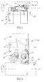
Fig. 1 is a perspective view of a cutting tool in accordance with a first embodiment of the present invention; -
Fig. 1a is a detailed perspective view of the cutting tool shown inFig. 1 ; -
Fig. 2 is a top view of the cutting tool shown inFig. 1 ; -
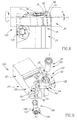
Fig. 3 is an exploded perspective view of the cutting tool shown inFig. 1 ; -
Fig. 4 is a top view of an adjustment member in accordance with the first embodiment of the present invention; -
Fig. 5 is a front view of the adjustment member shown inFig. 4 ; -
Fig. 6 is a top view of a cutting insert in accordance with some embodiments of the present invention; -
Fig. 7 is a bottom view of the cutting insert shown inFig. 6 ; -
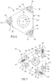
Fig. 8 is a perspective view of a cutting tool in accordance with a second embodiment of the present invention; -
Fig. 9 is an exploded perspective view of the cutting tool shown inFig. 8 ; -
Fig. 10 is a top view of an adjustment member in accordance with the second embodiment of the present invention; and -
Fig. 11 is a front view of the adjustment member shown inFig. 10 . - Attention is first drawn to
Figs. 1 to 3 ,8 and 9 , showing acutting tool cutting tool cutting insert 22, atool holder 24, and anadjustment member - The
cutting insert 22 has at least onecutting portion 28 and may be manufactured by form pressing and sintering a cemented carbide, such as tungsten carbide, and may be coated or uncoated. - The
tool holder 24, which may be manufactured from hardened steel, has aninsert holder portion shank portion 32, theinsert holder portion shank portion 32. - The
adjustment member insert holder portion cutting insert 22. - In some embodiments of the present invention, the
adjustment member - The
cutting insert 22 is removably secured to theinsert holder portion fastener 34, at a cutting position in which theoperative cutting portion 28 encounters aworkpiece 36 at an insert cutting angle α. - In some embodiments of the present invention, the
cutting insert 22 may be an indexable threading insert with a plurality of cuttingportions 28, eachcutting portion 28 having twocutting edges cutting tool - For threading operations, as shown in
Figs. 1a and8 , the insert cutting angle α is the inclination angle of the twocutting edges operative cutting portion 28 relative to a central axis C of therotating workpiece 36. The inclination angle of a threading insert is a well known term used in the field of threading operations and typically adjusted to equal the helix angle of the thread being cut, in order to provide equal clearance for both cutting edges. - Actuation of the
adjustment member - It should be understood that throughout the description and claims of the present invention, the term "actuation" describes the act of initiating movement of the
adjustment member - In some embodiments of the present invention, the
cutting tool single adjustment member - Also, in some embodiments of the present invention, actuation of the
adjustment member cutting tool - To change the insert cutting angle α, one may first partially unclamp the
cutting insert 22, rotate theadjustment member cutting tool - untightening the
fastener 34, - actuating the
adjustment member - retightening the
fastener 34. - Following the untightening of the
fastener 34, actuation of theadjustment member adjustment member - The insert cutting angle α may be increased by rotating the
adjustment member adjustment member - In some embodiments of the present invention, the
insert holder portion adjustment member - In some embodiments of the present invention, the
adjustment member insert holder portion adjustment member adjustment member - As shown in
Figs. 3 ,5 ,9 and11 , theadjustment member planar base surface planar base surface corresponding seat surface insert holder portion - In some embodiments of the present invention, the
adjustment member insert 22. - As shown in
Figs. 4, 5 ,10 and 11 , theadjustment member top surface base surface side surface side surface adjustment supporting surface - As shown in
Figs. 6 and 7 , the cuttinginsert 22 may be a lay-down threading insert having opposing upper andlower surfaces peripheral surface 56 extending therebetween, with the twocutting edges portion 28 having an associatedrake surface 58 on the upper orlower surface - As shown in
Figs. 2 ,3 and9 , thefastener 34 may be in the form of a clampingscrew 60. - In some embodiments of the present invention, as shown in
Figs. 3 ,6 ,7 and9 , the upper andlower surfaces bore 62 extending therebetween, and the clampingscrew 60 may be located in the throughbore 62 and threadingly received in a screw bore 64 in theinsert holder portion - In other embodiments of the present invention (not shown), the
fastener 34 may be in the form of a clamping member, engaging with the throughbore 62 and/or one of the upper andlower surfaces - Also, in some embodiments of the present invention, the cutting
insert 22 may be generally triangular in shape, having three cuttingportions 28 and an equal number ofsupport zones 66, and theadjustment supporting surface support zone 66 distal from theoperative cutting portion 28. - The
rake surface 58 of theoperative cutting portion 28 may be on theupper surface 52, and the singleoperative support zone 66 may be on thelower surface 54. - In some embodiments of the present invention, as shown in
Fig. 7 , the cuttinginsert 22 may also include a plurality of V-shapedengagement ridges 68 equal to the number of cuttingportions 28, each V-shapedengagement ridge 68 located on thelower surface 54 adjacent an associated cuttingportion 28. Each V-shapedengagement ridge 68 may have twoflank surfaces 70 and an insert tilt axis A3, with the twoflank surfaces 70 parallely extending in the direction of the insert tilt axis A3. Each V-shapedengagement ridge 68 may be divided into more than one separate engagement portion, and exactly one of the V-shapedengagement ridges 68 may interface with a corresponding V-shapedengagement groove 72 in theinsert holder portion - Each
support zone 66 may be located on a single engagement portion of each V-shapedengagement ridge 68, on a surface separating the two flank surfaces 70. - Also, in some embodiments of the present invention, as shown in
Fig. 2 , theinsert holder portion engagement ridge 68 may be perpendicular to the first plane P1 for each value of the insert cutting angle α. It can also be understood that the insert tilt axis A3 of the operative V-shapedengagement ridge 68 may be perpendicular to the first plane P1 for each rotational position of theadjustment member - The first plane P1 may be parallel to the central axis C of the
rotating workpiece 36. - In some embodiments of the present invention, the insert cutting angle α may have an adjustment range R which can be attained in less than one revolution of the
adjustment member - In a first embodiment of the present invention, as shown in
Figs. 4 and 5 , theadjustment supporting surface 50 may be formed on thetop surface 46 of theadjustment member 26. Theadjustment supporting surface 50 may be helically step shaped, having a supporting surface axis A4 coaxial with the first axis A1, and an adjustment height H from thebase surface 42 which increases or decreases about the supporting surface axis A4. The helically step shapedadjustment supporting surface 50 may comprise a plurality ofstep segments 74, eachstep segment 74 perpendicular to the first axis A1 and representing a distinct value of insert cutting angle α. - In the first embodiment of the present invention, the
top surface 46 may face in generally the same direction as therake surface 58 of theoperative cutting portion 28, and theside surface 48 may be cylindrical. - In a second embodiment of the present invention, as shown in
Figs. 10 and 11 , theside surface 148 of theadjustment member 126 may be non-cylindrical, and theadjustment supporting surface 150 may be formed on theside surface 148, having a radial adjustment distance D from the first axis A1 which continuously increases or decreases about the first axis A1. - In the second embodiment of the present invention, the
top surface 146 may face in a generally transverse direction to therake surface 58 of theoperative cutting portion 28. - In both embodiments, a first portion of the adjustment
member supporting surface insert 22 at theactive support zone 66 located away from the insert tilt axis A3 associated with theoperative cutting portion 28. Rotation of theadjustment member insert holder portion surface insert 22. This causes a change in both the elevation of the secured cuttinginsert 22 at theactive support zone 66 and in the tilt of the secured cuttinginsert 22 about the insert tilt axis A3, relative to theinsert holder portion - In some embodiments of the present invention, the
adjustment member - Although, in some embodiments of the present invention, the
adjustment member adjustment member 126 may be employed to define distinct step increases or decreases of the insert cutting angle α, and thus aid the operator. - In the first embodiment of the present invention, as shown in
Fig. 2 , the cuttingtool 20 may be configured to physically prevent the operator from actuating theadjustment member 26 until the cuttinginsert 22 has been unclamped, such as by untightening thefastener 34, and partially rotated. - In some embodiments of the present invention, the
adjustment member non-threaded retaining portion 82 which keeps theadjustment member insert holder portion adjustment member portion 82 may keep thebase surface seat surface insert holder portion - As shown in
Figs. 3 ,5 ,9 and11 , the non-threaded retainingportion 82 is insertable into theinsert holder portion resilient legs 76 extending away from thebase surface cylindrical wall 78 of a holdingcavity 80 in theseat surface cylindrical wall 78 of the holdingcavity 80. - Although the present invention has been described to a certain degree of particularity, it should be understood that various alterations and modifications could be made without departing from or scope of the invention as hereinafter claimed.
Claims (15)
- A cutting tool (20, 120) comprising:a cutting insert (22), a tool holder (24), and an adjustment member (26, 126);the cutting insert (22) having at least one cutting portion (28),the tool holder (24) having an insert holder portion (30, 130) and a shank portion (32), the insert holder portion (30, 130) being rigidly fixed to the shank portion (32),the adjustment member (26, 126), having a first axis (A1), being non-threadingly retained on the insert holder portion (30, 130), and operatively connected to the cutting insert (22), andthe cutting insert (22) being removably secured directly to the insert holder portion (30, 130) by means of a fastener (34), at a cutting position in which the operative cutting portion (28) encounters a workpiece (36) at an insert cutting angle (α),wherein actuation of the adjustment member (26, 126) causes an increase or decrease of the insert cutting angle (α), and is performed by rotating the adjustment member (26, 126) about its first axis (A1).
- The cutting tool (20, 120) according to claim 1, wherein the adjustment member (26, 126) directly engages the cutting insert (22), and/or
wherein actuation of the adjustment member (26, 126) is performed without removing any components from the cutting tool (20, 120). - The cutting tool (20, 120) according to claim 1 or 2, wherein the adjustment member (26, 126) is in a fixed translational position on the insert holder portion (30, 130), and
wherein actuation of the adjustment member (26, 126) is performed solely by rotating the adjustment member (26, 126) about its first axis (A1). - The cutting tool (20, 120) according to any one of the preceding claims, wherein the insert cutting angle (α) is increased by rotating the adjustment member (26, 126) in one direction about its first axis (A1) and decreased by rotating the adjustment member (26, 126) in an opposite direction about its first axis (A1), and/or
wherein the insert cutting angle (α) has an adjustment range (R) which can be attained in less than one revolution of the adjustment member (26, 126) about its first axis (A1). - The cutting tool (20, 120) according to any one of the preceding claims, wherein the insert holder portion (30, 130) has a second axis (A2), and the first axis (A1) and the second axis (A2) are coaxial, and/or
wherein the adjustment member (26, 126) has a planar base surface (42, 142) perpendicular to the first axis (A1), and the planar base surface (42, 142) is in contact with a corresponding seat surface (44, 144) on the insert holder portion (30, 130): - The cutting tool (20, 120) according to claim 5, wherein the adjustment member (26, 126) has a top surface (46, 146) opposing the base surface (42, 142), and a side surface (48, 148) extending therebetween,
wherein the top or side surface (46, 148) comprises an adjustment supporting surface (50, 150),
wherein the cutting insert (22) has at least one support zone (66), and
wherein the adjustment supporting surface (50, 150) is in contact with exactly one support zone (66) distal from the operative cutting portion (28). - The cutting tool (20) according to claim 6, wherein the adjustment supporting surface (50) is formed on the top surface (46), and
wherein the adjustment supporting surface (50) is helically step shaped, having a supporting surface axis (A4) coaxial with the first axis (A1), and an adjustment height (H) from the base surface (42) which increases or decreases about the supporting surface axis (A4). - The cutting tool (20, 120) according to any one of the preceding claims, wherein the cutting tool (20, 120) is used in threading operations,
wherein the cutting insert (22) has a plurality of cutting portions (28), each cutting portion (28) having two cutting edges (38, 40), and
wherein the insert cutting angle (α) is the inclination angle of the two cutting edges (38, 40) of the operative cutting portion (28) relative to a central axis (C) of the rotating workpiece (36). - The cutting tool (20, 120) according to claim 8, wherein the cutting insert (22) is a lay-down threading insert having opposing upper and lower surfaces (52, 54) and a peripheral surface (56) extending therebetween,
wherein the two cutting edges (38, 40) of each cutting portion (28) have an associated rake surface (58) on the upper or lower surface (52, 54). - The cutting tool (20, 120) according to claim 9, wherein the fastener (34) is in the form of a clamping screw (60),
wherein upper and lower surfaces (52, 54) have a through bore (62) extending therebetween, and
wherein the clamping screw (60) is located in the through bore (62) and threadingly received in a screw bore (64) in the insert holder portion (30, 130). - The cutting tool (20, 120) according to any one of the preceding claims, wherein each of the at least one cutting portion (28) has an insert tilt axis (A3),
wherein the insert holder portion (30, 130) has a first plane (P1), and
wherein the insert tilt axis (A3) of the operative cutting portion (28) is perpendicular to the first plane (P1) for each value of the insert cutting angle (α). - The cutting tool (20, 120) according to any one of the preceding claims, comprising a single adjustment member (26, 126), and
wherein the adjustment member (26, 126) is capable of being actuated directly by an operator. - A method of increasing or decreasing an insert cutting angle (α) of a cutting tool (20, 120) relative to a workpiece (36), the cutting tool (20, 120) comprising:a cutting insert (22), a tool holder (24), and an adjustment member (26, 126);the cutting insert (22) having at least one cutting portion (28),the tool holder (24) having a insert holder portion (30,130) and a shank portion (32), the insert holder portion (30, 130) being rigidly fixed to the shank portion (32),the insert adjustment member (26, 126) being non-threadingly retained on the insert holder portion (30, 130), and operatively connected to the cutting insert (22), andthe cutting insert (22) being removably secured directly to the insert holder portion (30,the method comprising the steps of:
130) by means of a fastener (34),untightening the fastener (34),actuating the adjustment member (26, 126) without removing any components from the cutting tool (20, 120), andretightening the fastener (34), wherein actuation of the adjustment member (26, 126) is performed by rotating the adjustment member (26, 126) about its first axis (A1). - The method according to claim 13, wherein the adjustment member (26, 126) is in a fixed translational position in the insert holder portion (30, 130), and/or
wherein the adjustment member (26, 126) has a first axis (A1), and actuation of the adjustment member (26, 126) is performed solely by rotating the adjustment member (26, 126) about its first axis (A1), and/or
wherein the adjustment member (26, 126) directly engages the cutting insert (22), and the adjustment member (26, 126) is capable of being actuated directly by the operator. - A cutting tool (20, 120) comprising:a tool holder (24) having an insert holder portion (30, 130);a cutting insert (22) removably secured to the insert holder portion (30, 130), the cutting insert having an operative cutting portion (28) provided with an associated insert tilt axis (A3) and an active support zone (66) located away from the insert tilt axis (A3); andan adjustment member (26, 126) non-threadingly retained on the insert holder portion (30, 130) and having a first axis (A1) and a supporting surface (50, 150) at least a first portion of which opposes the cutting insert (22) at the active support zone (66); wherein:rotation of the adjustment member (26, 126) about the first axis (A1) and relative to the insert holder portion (30, 130) results in a second portion of the supporting surface (50, 150) opposing the active support zone (66), and changes in both the elevation of the secured cutting insert (22) at said active support zone (66) and the tilt of the secured cutting insert (22) about the insert tilt axis (A3), relative to the insert holder portion (30, 130).
Priority Applications (1)
| Application Number | Priority Date | Filing Date | Title |
|---|---|---|---|
| PL12750824T PL2736664T3 (en) | 2011-07-26 | 2012-07-09 | Adjustable cutting tool |
Applications Claiming Priority (2)
| Application Number | Priority Date | Filing Date | Title |
|---|---|---|---|
| US201161511836P | 2011-07-26 | 2011-07-26 | |
| PCT/IL2012/050239 WO2013014666A1 (en) | 2011-07-26 | 2012-07-09 | Adjustable cutting tool |
Publications (2)
| Publication Number | Publication Date |
|---|---|
| EP2736664A1 EP2736664A1 (en) | 2014-06-04 |
| EP2736664B1 true EP2736664B1 (en) | 2017-02-22 |
Family
ID=46727278
Family Applications (1)
| Application Number | Title | Priority Date | Filing Date |
|---|---|---|---|
| EP12750824.0A Not-in-force EP2736664B1 (en) | 2011-07-26 | 2012-07-09 | Adjustable cutting tool |
Country Status (13)
| Country | Link |
|---|---|
| US (1) | US8506209B2 (en) |
| EP (1) | EP2736664B1 (en) |
| JP (1) | JP5955959B2 (en) |
| KR (1) | KR101716009B1 (en) |
| CN (1) | CN103702787B (en) |
| BR (1) | BR112014000140A2 (en) |
| CA (1) | CA2842280C (en) |
| ES (1) | ES2624139T3 (en) |
| IL (1) | IL230176A (en) |
| PL (1) | PL2736664T3 (en) |
| PT (1) | PT2736664T (en) |
| RU (1) | RU2599059C2 (en) |
| WO (1) | WO2013014666A1 (en) |
Families Citing this family (4)
| Publication number | Priority date | Publication date | Assignee | Title |
|---|---|---|---|---|
| JP6305339B2 (en) * | 2012-08-06 | 2018-04-04 | 株式会社タンガロイ | Blade adjustment device |
| CN105642888B (en) * | 2016-01-29 | 2017-09-29 | 柳州市安龙机械设备有限公司 | The processing method of hard alloy mine lathe tool |
| JP6640149B2 (en) * | 2017-05-25 | 2020-02-05 | 京セラ株式会社 | Electromagnetic wave detection device and information acquisition system |
| US11534838B1 (en) * | 2021-06-08 | 2022-12-27 | Iscar, Ltd. | Indexable lay-down cutting insert having a central body portion and three circumferentially spaced cutting portions, and cutting tool |
Citations (3)
| Publication number | Priority date | Publication date | Assignee | Title |
|---|---|---|---|---|
| GB1276955A (en) * | 1970-07-14 | 1972-06-07 | Frank Sirola | Improvements in or relating to cutting tools |
| FR2506642A1 (en) * | 1981-05-29 | 1982-12-03 | Garih Claude | Adjustable lathe tool with polygonal plate cutter - has cutter which can swivel and has alternative rear edge notches engaged by locking bolt |
| DE3818970C1 (en) * | 1988-06-03 | 1989-11-30 | Fa. Otto Steck, 7022 Leinfelden-Echterdingen, De |
Family Cites Families (20)
| Publication number | Priority date | Publication date | Assignee | Title |
|---|---|---|---|---|
| DE449071C (en) | 1926-11-04 | 1927-08-31 | Ludw Loewe & Co Act Ges | Adjustment device for cutting bars |
| BE348840A (en) | 1927-02-15 | |||
| US2369555A (en) * | 1941-10-08 | 1945-02-13 | Freeman Harry Howard | Tool-adjusting means |
| US2346084A (en) * | 1943-03-05 | 1944-04-04 | Sanocki Stanley | Tool |
| SU83861A1 (en) * | 1949-01-31 | 1949-11-30 | Д.И. Рыжков | Turning cutter with holder |
| US2903781A (en) * | 1955-07-14 | 1959-09-15 | Arthur F Hudson | Metal cutting tool and holder |
| US3520042A (en) | 1967-10-11 | 1970-07-14 | Carmet Co | Adjustable threading tool |
| US3802043A (en) | 1972-10-30 | 1974-04-09 | C Garih | Milling cutter with mechanically clamped teeth |
| US3853422A (en) * | 1973-11-02 | 1974-12-10 | Erickson Tool Co | Adjustable boring bar |
| SU973247A1 (en) * | 1981-04-06 | 1982-11-15 | Предприятие П/Я А-1857 | Adjustable tool holder |
| GB8327581D0 (en) | 1983-10-14 | 1983-11-16 | Stellram Ltd | Thread cutting |
| SU1355376A1 (en) * | 1985-07-15 | 1987-11-30 | Краматорское Станкостроительное Производственное Объединение | Cutter holder |
| JPH0513454Y2 (en) * | 1986-10-03 | 1993-04-09 | ||
| JPH01148206U (en) * | 1988-03-29 | 1989-10-13 | ||
| SE512751C2 (en) * | 1997-04-11 | 2000-05-08 | Sandvik Ab | Cutting tools |
| US7014393B2 (en) * | 2003-02-07 | 2006-03-21 | Dr. Joerg Guehring | Clamping and adjustment apparatus for a cutting tool |
| US20080253847A1 (en) | 2004-08-19 | 2008-10-16 | Manchester Tool Company | Adjustable Machine Tool Cutting Insert Holder Apparatus |
| DE102006005379B4 (en) * | 2006-02-03 | 2015-02-12 | Kennametal Inc. | Combination tool and method of machining a borehole and its bore surface |
| RU60414U1 (en) * | 2006-04-07 | 2007-01-27 | Московский государственный технологический университет "СТАНКИН" | THREADED CUTTER WITH TURNING HOLDER |
| SE530698C2 (en) * | 2006-12-21 | 2008-08-19 | Sandvik Intellectual Property | Turning tools, as well as the basic body and support plate for such tools |
-
2012
- 2012-03-08 US US13/415,452 patent/US8506209B2/en active Active
- 2012-07-09 EP EP12750824.0A patent/EP2736664B1/en not_active Not-in-force
- 2012-07-09 WO PCT/IL2012/050239 patent/WO2013014666A1/en active Application Filing
- 2012-07-09 ES ES12750824.0T patent/ES2624139T3/en active Active
- 2012-07-09 JP JP2014522211A patent/JP5955959B2/en not_active Expired - Fee Related
- 2012-07-09 CN CN201280036773.4A patent/CN103702787B/en not_active Expired - Fee Related
- 2012-07-09 PL PL12750824T patent/PL2736664T3/en unknown
- 2012-07-09 PT PT127508240T patent/PT2736664T/en unknown
- 2012-07-09 KR KR1020147001322A patent/KR101716009B1/en active IP Right Grant
- 2012-07-09 RU RU2014106987/02A patent/RU2599059C2/en not_active IP Right Cessation
- 2012-07-09 BR BR112014000140A patent/BR112014000140A2/en not_active Application Discontinuation
- 2012-07-09 CA CA2842280A patent/CA2842280C/en not_active Expired - Fee Related
-
2013
- 2013-12-26 IL IL230176A patent/IL230176A/en active IP Right Grant
Patent Citations (3)
| Publication number | Priority date | Publication date | Assignee | Title |
|---|---|---|---|---|
| GB1276955A (en) * | 1970-07-14 | 1972-06-07 | Frank Sirola | Improvements in or relating to cutting tools |
| FR2506642A1 (en) * | 1981-05-29 | 1982-12-03 | Garih Claude | Adjustable lathe tool with polygonal plate cutter - has cutter which can swivel and has alternative rear edge notches engaged by locking bolt |
| DE3818970C1 (en) * | 1988-06-03 | 1989-11-30 | Fa. Otto Steck, 7022 Leinfelden-Echterdingen, De |
Also Published As
| Publication number | Publication date |
|---|---|
| CA2842280A1 (en) | 2013-01-31 |
| RU2599059C2 (en) | 2016-10-10 |
| ES2624139T3 (en) | 2017-07-13 |
| EP2736664A1 (en) | 2014-06-04 |
| KR101716009B1 (en) | 2017-03-13 |
| CN103702787B (en) | 2016-11-09 |
| US8506209B2 (en) | 2013-08-13 |
| WO2013014666A1 (en) | 2013-01-31 |
| IL230176A (en) | 2016-12-29 |
| PT2736664T (en) | 2017-03-30 |
| JP5955959B2 (en) | 2016-07-20 |
| US20130028671A1 (en) | 2013-01-31 |
| PL2736664T3 (en) | 2017-07-31 |
| KR20140039303A (en) | 2014-04-01 |
| CN103702787A (en) | 2014-04-02 |
| RU2014106987A (en) | 2015-10-27 |
| CA2842280C (en) | 2016-08-09 |
| BR112014000140A2 (en) | 2017-02-07 |
| JP2014521525A (en) | 2014-08-28 |
Similar Documents
| Publication | Publication Date | Title |
|---|---|---|
| EP3107675B1 (en) | Cutting tool having adjustable insert cutting angle | |
| US6877934B2 (en) | Milling head for thread whirling | |
| US20120099935A1 (en) | Cutting Tool and Cutting Insert Therefor | |
| US7534075B2 (en) | Knife plate and tool for machining bore surfaces | |
| JP6627174B2 (en) | Cutting edge position adjustment mechanism and cutting edge replaceable cutting tool | |
| EP2736664B1 (en) | Adjustable cutting tool | |
| EP2981386B1 (en) | Indexable double-sided milling cutting insert | |
| JP2019511382A (en) | Face grooving tool for metal cutting | |
| US10286459B2 (en) | Machining tool | |
| EP2788137A1 (en) | Tool holder and method for clamping a cutting insert therein | |
| JP5971577B2 (en) | Blade adjustment mechanism | |
| EP3305449B1 (en) | A face milling tool and a tangential cutting insert therefor | |
| JP2003145320A (en) | Throwaway tip, and clamp mechanism for the same | |
| CN114632963A (en) | Method for positioning machining tool and machining tool | |
| JP2006247776A (en) | Milling cutter | |
| JPH10296516A (en) | Throw-away tip | |
| JPH10296515A (en) | Throw-away cutting tool | |
| IL232810A (en) | Tool holder and method for clamping a cutting insert therein |
Legal Events
| Date | Code | Title | Description |
|---|---|---|---|
| PUAI | Public reference made under article 153(3) epc to a published international application that has entered the european phase |
Free format text: ORIGINAL CODE: 0009012 |
|
| 17P | Request for examination filed |
Effective date: 20140206 |
|
| AK | Designated contracting states |
Kind code of ref document: A1 Designated state(s): AL AT BE BG CH CY CZ DE DK EE ES FI FR GB GR HR HU IE IS IT LI LT LU LV MC MK MT NL NO PL PT RO RS SE SI SK SM TR |
|
| DAX | Request for extension of the european patent (deleted) | ||
| 17Q | First examination report despatched |
Effective date: 20150511 |
|
| RIC1 | Information provided on ipc code assigned before grant |
Ipc: B23B 29/04 20060101ALI20160706BHEP Ipc: B23B 29/22 20060101ALI20160706BHEP Ipc: B23B 27/16 20060101AFI20160706BHEP |
|
| GRAP | Despatch of communication of intention to grant a patent |
Free format text: ORIGINAL CODE: EPIDOSNIGR1 |
|
| INTG | Intention to grant announced |
Effective date: 20160824 |
|
| GRAS | Grant fee paid |
Free format text: ORIGINAL CODE: EPIDOSNIGR3 |
|
| GRAA | (expected) grant |
Free format text: ORIGINAL CODE: 0009210 |
|
| AK | Designated contracting states |
Kind code of ref document: B1 Designated state(s): AL AT BE BG CH CY CZ DE DK EE ES FI FR GB GR HR HU IE IS IT LI LT LU LV MC MK MT NL NO PL PT RO RS SE SI SK SM TR |
|
| REG | Reference to a national code |
Ref country code: GB Ref legal event code: FG4D |
|
| REG | Reference to a national code |
Ref country code: CH Ref legal event code: EP |
|
| REG | Reference to a national code |
Ref country code: AT Ref legal event code: REF Ref document number: 868856 Country of ref document: AT Kind code of ref document: T Effective date: 20170315 |
|
| REG | Reference to a national code |
Ref country code: IE Ref legal event code: FG4D |
|
| REG | Reference to a national code |
Ref country code: PT Ref legal event code: SC4A Ref document number: 2736664 Country of ref document: PT Date of ref document: 20170330 Kind code of ref document: T Free format text: AVAILABILITY OF NATIONAL TRANSLATION Effective date: 20170324 |
|
| REG | Reference to a national code |
Ref country code: DE Ref legal event code: R096 Ref document number: 602012028937 Country of ref document: DE |
|
| REG | Reference to a national code |
Ref country code: SE Ref legal event code: TRGR |
|
| REG | Reference to a national code |
Ref country code: LT Ref legal event code: MG4D |
|
| REG | Reference to a national code |
Ref country code: NL Ref legal event code: MP Effective date: 20170222 |
|
| REG | Reference to a national code |
Ref country code: FR Ref legal event code: PLFP Year of fee payment: 6 |
|
| REG | Reference to a national code |
Ref country code: ES Ref legal event code: FG2A Ref document number: 2624139 Country of ref document: ES Kind code of ref document: T3 Effective date: 20170713 |
|
| PG25 | Lapsed in a contracting state [announced via postgrant information from national office to epo] |
Ref country code: NO Free format text: LAPSE BECAUSE OF FAILURE TO SUBMIT A TRANSLATION OF THE DESCRIPTION OR TO PAY THE FEE WITHIN THE PRESCRIBED TIME-LIMIT Effective date: 20170522 Ref country code: LT Free format text: LAPSE BECAUSE OF FAILURE TO SUBMIT A TRANSLATION OF THE DESCRIPTION OR TO PAY THE FEE WITHIN THE PRESCRIBED TIME-LIMIT Effective date: 20170222 Ref country code: FI Free format text: LAPSE BECAUSE OF FAILURE TO SUBMIT A TRANSLATION OF THE DESCRIPTION OR TO PAY THE FEE WITHIN THE PRESCRIBED TIME-LIMIT Effective date: 20170222 Ref country code: HR Free format text: LAPSE BECAUSE OF FAILURE TO SUBMIT A TRANSLATION OF THE DESCRIPTION OR TO PAY THE FEE WITHIN THE PRESCRIBED TIME-LIMIT Effective date: 20170222 Ref country code: GR Free format text: LAPSE BECAUSE OF FAILURE TO SUBMIT A TRANSLATION OF THE DESCRIPTION OR TO PAY THE FEE WITHIN THE PRESCRIBED TIME-LIMIT Effective date: 20170523 |
|
| PG25 | Lapsed in a contracting state [announced via postgrant information from national office to epo] |
Ref country code: BG Free format text: LAPSE BECAUSE OF FAILURE TO SUBMIT A TRANSLATION OF THE DESCRIPTION OR TO PAY THE FEE WITHIN THE PRESCRIBED TIME-LIMIT Effective date: 20170522 Ref country code: NL Free format text: LAPSE BECAUSE OF FAILURE TO SUBMIT A TRANSLATION OF THE DESCRIPTION OR TO PAY THE FEE WITHIN THE PRESCRIBED TIME-LIMIT Effective date: 20170222 Ref country code: RS Free format text: LAPSE BECAUSE OF FAILURE TO SUBMIT A TRANSLATION OF THE DESCRIPTION OR TO PAY THE FEE WITHIN THE PRESCRIBED TIME-LIMIT Effective date: 20170222 Ref country code: LV Free format text: LAPSE BECAUSE OF FAILURE TO SUBMIT A TRANSLATION OF THE DESCRIPTION OR TO PAY THE FEE WITHIN THE PRESCRIBED TIME-LIMIT Effective date: 20170222 |
|
| PG25 | Lapsed in a contracting state [announced via postgrant information from national office to epo] |
Ref country code: EE Free format text: LAPSE BECAUSE OF FAILURE TO SUBMIT A TRANSLATION OF THE DESCRIPTION OR TO PAY THE FEE WITHIN THE PRESCRIBED TIME-LIMIT Effective date: 20170222 Ref country code: RO Free format text: LAPSE BECAUSE OF FAILURE TO SUBMIT A TRANSLATION OF THE DESCRIPTION OR TO PAY THE FEE WITHIN THE PRESCRIBED TIME-LIMIT Effective date: 20170222 Ref country code: SK Free format text: LAPSE BECAUSE OF FAILURE TO SUBMIT A TRANSLATION OF THE DESCRIPTION OR TO PAY THE FEE WITHIN THE PRESCRIBED TIME-LIMIT Effective date: 20170222 |
|
| REG | Reference to a national code |
Ref country code: DE Ref legal event code: R097 Ref document number: 602012028937 Country of ref document: DE |
|
| PG25 | Lapsed in a contracting state [announced via postgrant information from national office to epo] |
Ref country code: DK Free format text: LAPSE BECAUSE OF FAILURE TO SUBMIT A TRANSLATION OF THE DESCRIPTION OR TO PAY THE FEE WITHIN THE PRESCRIBED TIME-LIMIT Effective date: 20170222 Ref country code: SM Free format text: LAPSE BECAUSE OF FAILURE TO SUBMIT A TRANSLATION OF THE DESCRIPTION OR TO PAY THE FEE WITHIN THE PRESCRIBED TIME-LIMIT Effective date: 20170222 |
|
| PLBE | No opposition filed within time limit |
Free format text: ORIGINAL CODE: 0009261 |
|
| STAA | Information on the status of an ep patent application or granted ep patent |
Free format text: STATUS: NO OPPOSITION FILED WITHIN TIME LIMIT |
|
| 26N | No opposition filed |
Effective date: 20171123 |
|
| PG25 | Lapsed in a contracting state [announced via postgrant information from national office to epo] |
Ref country code: SI Free format text: LAPSE BECAUSE OF FAILURE TO SUBMIT A TRANSLATION OF THE DESCRIPTION OR TO PAY THE FEE WITHIN THE PRESCRIBED TIME-LIMIT Effective date: 20170222 |
|
| REG | Reference to a national code |
Ref country code: CH Ref legal event code: PL |
|
| REG | Reference to a national code |
Ref country code: IE Ref legal event code: MM4A |
|
| PG25 | Lapsed in a contracting state [announced via postgrant information from national office to epo] |
Ref country code: IE Free format text: LAPSE BECAUSE OF NON-PAYMENT OF DUE FEES Effective date: 20170709 Ref country code: CH Free format text: LAPSE BECAUSE OF NON-PAYMENT OF DUE FEES Effective date: 20170731 Ref country code: LI Free format text: LAPSE BECAUSE OF NON-PAYMENT OF DUE FEES Effective date: 20170731 |
|
| REG | Reference to a national code |
Ref country code: BE Ref legal event code: MM Effective date: 20170731 |
|
| REG | Reference to a national code |
Ref country code: FR Ref legal event code: PLFP Year of fee payment: 7 |
|
| PG25 | Lapsed in a contracting state [announced via postgrant information from national office to epo] |
Ref country code: LU Free format text: LAPSE BECAUSE OF NON-PAYMENT OF DUE FEES Effective date: 20170709 |
|
| PG25 | Lapsed in a contracting state [announced via postgrant information from national office to epo] |
Ref country code: BE Free format text: LAPSE BECAUSE OF NON-PAYMENT OF DUE FEES Effective date: 20170731 |
|
| PG25 | Lapsed in a contracting state [announced via postgrant information from national office to epo] |
Ref country code: MT Free format text: LAPSE BECAUSE OF NON-PAYMENT OF DUE FEES Effective date: 20170709 |
|
| REG | Reference to a national code |
Ref country code: AT Ref legal event code: UEP Ref document number: 868856 Country of ref document: AT Kind code of ref document: T Effective date: 20170222 |
|
| PG25 | Lapsed in a contracting state [announced via postgrant information from national office to epo] |
Ref country code: HU Free format text: LAPSE BECAUSE OF FAILURE TO SUBMIT A TRANSLATION OF THE DESCRIPTION OR TO PAY THE FEE WITHIN THE PRESCRIBED TIME-LIMIT; INVALID AB INITIO Effective date: 20120709 Ref country code: MC Free format text: LAPSE BECAUSE OF FAILURE TO SUBMIT A TRANSLATION OF THE DESCRIPTION OR TO PAY THE FEE WITHIN THE PRESCRIBED TIME-LIMIT Effective date: 20170222 |
|
| PGFP | Annual fee paid to national office [announced via postgrant information from national office to epo] |
Ref country code: CZ Payment date: 20190617 Year of fee payment: 8 Ref country code: IT Payment date: 20190523 Year of fee payment: 8 Ref country code: PT Payment date: 20190522 Year of fee payment: 8 Ref country code: PL Payment date: 20190521 Year of fee payment: 8 |
|
| PGFP | Annual fee paid to national office [announced via postgrant information from national office to epo] |
Ref country code: FR Payment date: 20190625 Year of fee payment: 8 Ref country code: SE Payment date: 20190624 Year of fee payment: 8 |
|
| PG25 | Lapsed in a contracting state [announced via postgrant information from national office to epo] |
Ref country code: CY Free format text: LAPSE BECAUSE OF NON-PAYMENT OF DUE FEES Effective date: 20170222 |
|
| PGFP | Annual fee paid to national office [announced via postgrant information from national office to epo] |
Ref country code: ES Payment date: 20190808 Year of fee payment: 8 Ref country code: TR Payment date: 20190704 Year of fee payment: 8 Ref country code: GB Payment date: 20190610 Year of fee payment: 8 |
|
| PG25 | Lapsed in a contracting state [announced via postgrant information from national office to epo] |
Ref country code: MK Free format text: LAPSE BECAUSE OF FAILURE TO SUBMIT A TRANSLATION OF THE DESCRIPTION OR TO PAY THE FEE WITHIN THE PRESCRIBED TIME-LIMIT Effective date: 20170222 |
|
| PGFP | Annual fee paid to national office [announced via postgrant information from national office to epo] |
Ref country code: AT Payment date: 20190621 Year of fee payment: 8 |
|
| PG25 | Lapsed in a contracting state [announced via postgrant information from national office to epo] |
Ref country code: AL Free format text: LAPSE BECAUSE OF FAILURE TO SUBMIT A TRANSLATION OF THE DESCRIPTION OR TO PAY THE FEE WITHIN THE PRESCRIBED TIME-LIMIT Effective date: 20170222 Ref country code: IS Free format text: LAPSE BECAUSE OF FAILURE TO SUBMIT A TRANSLATION OF THE DESCRIPTION OR TO PAY THE FEE WITHIN THE PRESCRIBED TIME-LIMIT Effective date: 20170622 |
|
| PGFP | Annual fee paid to national office [announced via postgrant information from national office to epo] |
Ref country code: DE Payment date: 20200611 Year of fee payment: 9 |
|
| PG25 | Lapsed in a contracting state [announced via postgrant information from national office to epo] |
Ref country code: CZ Free format text: LAPSE BECAUSE OF NON-PAYMENT OF DUE FEES Effective date: 20200709 |
|
| REG | Reference to a national code |
Ref country code: SE Ref legal event code: EUG |
|
| REG | Reference to a national code |
Ref country code: AT Ref legal event code: MM01 Ref document number: 868856 Country of ref document: AT Kind code of ref document: T Effective date: 20200709 |
|
| GBPC | Gb: european patent ceased through non-payment of renewal fee |
Effective date: 20200709 |
|
| PG25 | Lapsed in a contracting state [announced via postgrant information from national office to epo] |
Ref country code: GB Free format text: LAPSE BECAUSE OF NON-PAYMENT OF DUE FEES Effective date: 20200709 Ref country code: FR Free format text: LAPSE BECAUSE OF NON-PAYMENT OF DUE FEES Effective date: 20200731 Ref country code: PT Free format text: LAPSE BECAUSE OF NON-PAYMENT OF DUE FEES Effective date: 20210211 |
|
| PG25 | Lapsed in a contracting state [announced via postgrant information from national office to epo] |
Ref country code: SE Free format text: LAPSE BECAUSE OF NON-PAYMENT OF DUE FEES Effective date: 20200710 Ref country code: AT Free format text: LAPSE BECAUSE OF NON-PAYMENT OF DUE FEES Effective date: 20200709 |
|
| PG25 | Lapsed in a contracting state [announced via postgrant information from national office to epo] |
Ref country code: IT Free format text: LAPSE BECAUSE OF NON-PAYMENT OF DUE FEES Effective date: 20200709 |
|
| REG | Reference to a national code |
Ref country code: ES Ref legal event code: FD2A Effective date: 20211228 |
|
| PG25 | Lapsed in a contracting state [announced via postgrant information from national office to epo] |
Ref country code: ES Free format text: LAPSE BECAUSE OF NON-PAYMENT OF DUE FEES Effective date: 20200710 |
|
| REG | Reference to a national code |
Ref country code: DE Ref legal event code: R119 Ref document number: 602012028937 Country of ref document: DE |
|
| PG25 | Lapsed in a contracting state [announced via postgrant information from national office to epo] |
Ref country code: DE Free format text: LAPSE BECAUSE OF NON-PAYMENT OF DUE FEES Effective date: 20220201 |
|
| PG25 | Lapsed in a contracting state [announced via postgrant information from national office to epo] |
Ref country code: TR Free format text: LAPSE BECAUSE OF NON-PAYMENT OF DUE FEES Effective date: 20200709 |
|
| PG25 | Lapsed in a contracting state [announced via postgrant information from national office to epo] |
Ref country code: PL Free format text: LAPSE BECAUSE OF NON-PAYMENT OF DUE FEES Effective date: 20200709 |