EP2736642B1 - Fluid sample holders with piston valve - Google Patents
Fluid sample holders with piston valve Download PDFInfo
- Publication number
- EP2736642B1 EP2736642B1 EP12746061.6A EP12746061A EP2736642B1 EP 2736642 B1 EP2736642 B1 EP 2736642B1 EP 12746061 A EP12746061 A EP 12746061A EP 2736642 B1 EP2736642 B1 EP 2736642B1
- Authority
- EP
- European Patent Office
- Prior art keywords
- fluid
- sample holder
- stem
- sample
- sliding seal
- Prior art date
- Legal status (The legal status is an assumption and is not a legal conclusion. Google has not performed a legal analysis and makes no representation as to the accuracy of the status listed.)
- Active
Links
Images

Classifications
-
- B—PERFORMING OPERATIONS; TRANSPORTING
- B01—PHYSICAL OR CHEMICAL PROCESSES OR APPARATUS IN GENERAL
- B01L—CHEMICAL OR PHYSICAL LABORATORY APPARATUS FOR GENERAL USE
- B01L3/00—Containers or dishes for laboratory use, e.g. laboratory glassware; Droppers
- B01L3/02—Burettes; Pipettes
- B01L3/021—Pipettes, i.e. with only one conduit for withdrawing and redistributing liquids
- B01L3/0217—Pipettes, i.e. with only one conduit for withdrawing and redistributing liquids of the plunger pump type
-
- G—PHYSICS
- G01—MEASURING; TESTING
- G01N—INVESTIGATING OR ANALYSING MATERIALS BY DETERMINING THEIR CHEMICAL OR PHYSICAL PROPERTIES
- G01N30/00—Investigating or analysing materials by separation into components using adsorption, absorption or similar phenomena or using ion-exchange, e.g. chromatography or field flow fractionation
- G01N30/02—Column chromatography
- G01N30/04—Preparation or injection of sample to be analysed
- G01N30/16—Injection
-
- B—PERFORMING OPERATIONS; TRANSPORTING
- B01—PHYSICAL OR CHEMICAL PROCESSES OR APPARATUS IN GENERAL
- B01L—CHEMICAL OR PHYSICAL LABORATORY APPARATUS FOR GENERAL USE
- B01L3/00—Containers or dishes for laboratory use, e.g. laboratory glassware; Droppers
- B01L3/52—Containers specially adapted for storing or dispensing a reagent
-
- B—PERFORMING OPERATIONS; TRANSPORTING
- B01—PHYSICAL OR CHEMICAL PROCESSES OR APPARATUS IN GENERAL
- B01L—CHEMICAL OR PHYSICAL LABORATORY APPARATUS FOR GENERAL USE
- B01L3/00—Containers or dishes for laboratory use, e.g. laboratory glassware; Droppers
- B01L3/56—Labware specially adapted for transferring fluids
- B01L3/565—Seals
-
- B—PERFORMING OPERATIONS; TRANSPORTING
- B01—PHYSICAL OR CHEMICAL PROCESSES OR APPARATUS IN GENERAL
- B01L—CHEMICAL OR PHYSICAL LABORATORY APPARATUS FOR GENERAL USE
- B01L3/00—Containers or dishes for laboratory use, e.g. laboratory glassware; Droppers
- B01L3/56—Labware specially adapted for transferring fluids
- B01L3/567—Valves, taps or stop-cocks
-
- G—PHYSICS
- G01—MEASURING; TESTING
- G01N—INVESTIGATING OR ANALYSING MATERIALS BY DETERMINING THEIR CHEMICAL OR PHYSICAL PROPERTIES
- G01N1/00—Sampling; Preparing specimens for investigation
- G01N1/28—Preparing specimens for investigation including physical details of (bio-)chemical methods covered elsewhere, e.g. G01N33/50, C12Q
-
- G—PHYSICS
- G01—MEASURING; TESTING
- G01N—INVESTIGATING OR ANALYSING MATERIALS BY DETERMINING THEIR CHEMICAL OR PHYSICAL PROPERTIES
- G01N30/00—Investigating or analysing materials by separation into components using adsorption, absorption or similar phenomena or using ion-exchange, e.g. chromatography or field flow fractionation
- G01N30/02—Column chromatography
- G01N30/04—Preparation or injection of sample to be analysed
-
- B—PERFORMING OPERATIONS; TRANSPORTING
- B01—PHYSICAL OR CHEMICAL PROCESSES OR APPARATUS IN GENERAL
- B01L—CHEMICAL OR PHYSICAL LABORATORY APPARATUS FOR GENERAL USE
- B01L2300/00—Additional constructional details
- B01L2300/12—Specific details about materials
- B01L2300/123—Flexible; Elastomeric
-
- B—PERFORMING OPERATIONS; TRANSPORTING
- B01—PHYSICAL OR CHEMICAL PROCESSES OR APPARATUS IN GENERAL
- B01L—CHEMICAL OR PHYSICAL LABORATORY APPARATUS FOR GENERAL USE
- B01L2400/00—Moving or stopping fluids
- B01L2400/04—Moving fluids with specific forces or mechanical means
- B01L2400/0475—Moving fluids with specific forces or mechanical means specific mechanical means and fluid pressure
- B01L2400/0478—Moving fluids with specific forces or mechanical means specific mechanical means and fluid pressure pistons
-
- B—PERFORMING OPERATIONS; TRANSPORTING
- B01—PHYSICAL OR CHEMICAL PROCESSES OR APPARATUS IN GENERAL
- B01L—CHEMICAL OR PHYSICAL LABORATORY APPARATUS FOR GENERAL USE
- B01L2400/00—Moving or stopping fluids
- B01L2400/04—Moving fluids with specific forces or mechanical means
- B01L2400/0475—Moving fluids with specific forces or mechanical means specific mechanical means and fluid pressure
- B01L2400/0487—Moving fluids with specific forces or mechanical means specific mechanical means and fluid pressure fluid pressure, pneumatics
-
- B—PERFORMING OPERATIONS; TRANSPORTING
- B01—PHYSICAL OR CHEMICAL PROCESSES OR APPARATUS IN GENERAL
- B01L—CHEMICAL OR PHYSICAL LABORATORY APPARATUS FOR GENERAL USE
- B01L2400/00—Moving or stopping fluids
- B01L2400/06—Valves, specific forms thereof
- B01L2400/0633—Valves, specific forms thereof with moving parts
- B01L2400/065—Valves, specific forms thereof with moving parts sliding valves
-
- G—PHYSICS
- G01—MEASURING; TESTING
- G01N—INVESTIGATING OR ANALYSING MATERIALS BY DETERMINING THEIR CHEMICAL OR PHYSICAL PROPERTIES
- G01N30/00—Investigating or analysing materials by separation into components using adsorption, absorption or similar phenomena or using ion-exchange, e.g. chromatography or field flow fractionation
- G01N30/02—Column chromatography
- G01N30/04—Preparation or injection of sample to be analysed
- G01N30/16—Injection
- G01N30/20—Injection using a sampling valve
- G01N2030/204—Linearly moving valves, e.g. sliding valves
-
- G—PHYSICS
- G01—MEASURING; TESTING
- G01N—INVESTIGATING OR ANALYSING MATERIALS BY DETERMINING THEIR CHEMICAL OR PHYSICAL PROPERTIES
- G01N30/00—Investigating or analysing materials by separation into components using adsorption, absorption or similar phenomena or using ion-exchange, e.g. chromatography or field flow fractionation
- G01N30/02—Column chromatography
- G01N30/04—Preparation or injection of sample to be analysed
- G01N30/16—Injection
- G01N30/18—Injection using a septum or microsyringe
Definitions
- This invention relates to a sample holder, particularly, but not exclusively for allowing a fluid sample to be delivered to, or received from, a chromatography column or other fluid processing equipment.
- sample fluids need to be employed, for example in protein purification in a chromatographic process, in commercially available products, such sample fluids have been provided in fluid sample holders which have a reservoir connectable to a chromatography column.
- the reservoirs have an outlet for expelling the fluid and an inlet for accepting buffer fluid.
- the buffer fluid is pressurised to force the sample fluid out of the outlet.
- a moveable barrier between the sample fluid and the buffer fluid has been provided.
- this barrier is in the form of a sliding seal. It is known for the sliding seal to have a multi-part metal valve which opens when the seal reaches the end of its travel. This action allows the buffer fluid through the sliding seal to reach the sample fluid. This action allows buffer fluid to carry on pushing the sample fluid toward the chromatography column with minimal mixing and also allows the buffer fluid to attempt to clean the sample holder.
- the known valve is complicated, and consequently expensive. In addition, the large number of parts makes the valve difficult to clean.
- US5354483 discloses a sample holder including a separation element.
- a fluid sample holder suitable for allowing a fluid sample to be delivered to, or received from, fluid processing equipment
- the sample holder comprising: a fluid reservoir; a sample fluid port for providing fluid communication between said sample fluid reservoir and said fluid processing equipment; a buffer fluid port also for providing fluid communication between the reservoir and the fluid processing equipment; and a sliding seal within the reservoir including a sealing area which generally sealing engages with a wall of the reservoir thereby defining a first and a second fluid separated region in the reservoir, said first region being in fluid communication with the sample fluid port, and said second region being in fluid communication with the buffer fluid port, said sliding seal being displaceable within the reservoir by means of a pressure differential between said first and second regions to thereby change the respective volumes of the first and second regions, and the sliding seal including a valve
- the holder being characterised in that the valve is operable when the sliding seal reaches or substantially reaches an end of its displacement, and in that said valve including includes a stem having a tapered portion for cooperating
- the sliding seal includes a body which includes said aperture, and said stem is resiliently mounted to the body so that said stem displacement with respect to the body is resilient and biased into said cooperation.
- the stem is resiliently mounted to the body by means of a resilient diaphragm.
- the body is formed from a one piece moulding, for example a one piece plastics moulding, and preferably, the stem and diaphragm are formed from another one piece moulding, preferably a one piece plastics moulding.
- the body includes a skirt extending away from the sealing area, said skirt having a distal end which includes an inwardly directed protrusion for holding the diaphragm.
- the skirt is castellated.
- the stem has an end portion which abuts an end element of the holder to cause the stem displacement relative to the body.
- the sliding seal is cylindrical and has a centre axis, and the stem is displaceable parallel with the centre axis.
- fluid processing equipment including a sample holder or a sliding seal as claimed in any one of the preceding claims.
- a chromatography column including a sample holder or a sliding seal as claimed in any one of the preceding claims.
- a method for delivering fluids to a chromatography column apparatus including the steps of: providing a sample fluid holder containing a sample fluid; operating said apparatus to cause a buffer fluid to flow under a working pressure into said sample holder; causing a sliding seal within the sample holder to be displaced by said buffer fluid thereby causing only said sample fluid in the sample holder to exit the sample holder through a sample fluid port; allowing said displacement of said sliding seal to reach an end point thereat said working pressure is caused to increase; and causing the buffer fluid to flow through a valve in the sliding seal under the influence of said increased working pressure, when the sliding seal reaches or substantially reaches an end of its displacement, said valve including a stem having a tapered portion for cooperating with a complementary tapered aperture for substantially preventing fluid flow when so cooperating, said stem being displaceable away from said aperture and out of said cooperation at said end of its displacement, to open the valve.
- the method employs a sample holder having any one of the features according to the first aspect.
- the invention extends to any feature described herein for example, a sample holder, fluid processing equipment, or chromatography column substantially as described herein, optionally with reference to the drawings.
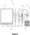
- FIG. 1 there is shown schematically fluid processing equipment 5 in the form of a chromatographic column 10, having a supply conduit 12, fed, in this case, by three fluid sample holders 20, 20' and 20". Each sample holder is the same but sample holder 20 is described in more detail below.
- the sample holder 20 has an internal first region 22 and second region 24. The first region 22 retains a sample fluid, whereas a second region 24 receives a buffer fluid 14.
- the sample holder 20 is selectively connected to a pump 16, via a selection valve 18, and is able to receive buffer fluid under pressure via a buffer fluid port 21.
- the sample holder 20 has a sliding seal 25 which moves under the influence of the pressurised buffer fluid 14 and causes the sample fluid in the first region 22 to flow out of the holder 20 through a sample fluid port 23.
- the sample fluid flows into the chromatography column 10 where it is employed.
- the sample could be used in a process for the purification of proteins.
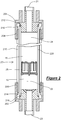
- the holder 20 has two end fittings 202 and 204 which each include an integral threaded portion 206 and 208 respectively.
- the threaded portions each fit with an outer tube 210 having complementary threaded ends.
- the two end fittings are rotated to clamp a pipe connector 212 and 214 to each end of an inner tube 220.
- a sealing ring 216 between each pipe connector and the inner tube 220 provides a fluid tight seal.
- the ports 23 and 21 are formed by apertures in the pipe connectors 214 and 212.
- Both the inner and outer tubes may be formed from transparent material, and it is preferred that the inner tube 220 is formed from glass material to provide a relatively inert sample wall surface and the outer tube is formed from a transparent or translucent plastics material to catch any shattered glass should the inner tube break under pressure.
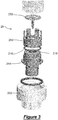
- FIG 3 shows an exploded view of the lower end components of the sample holder shown in Figure 2 .
- the sliding seal 25 has two pieces: a main body 250; and a stem piece 252, both described in more detail below.
- the main body 250 and a stem piece 252 are each formed from moulded material, for example a one piece moulded plastics, such as a polyetheretherketone (PEEK), a polypropylene (PP) or a high density polypropylene (HDPP).
- PEEK polyetheretherketone
- PP polypropylene
- HDPP high density polypropylene
- the pipe connector 214 has an abutment element 215 which abuts with the stem piece 252 when the sliding seal 25 is positioned adjacent the connector 214, that is, when the seal is at or approaching its limit of travel.
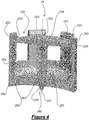
- Figure 4 shows an enlarged sectional view of the sliding seal 25.
- the seal is generally cylindrical with a centre axis CL along which the seal 25 will travel in use.
- the seal has an external sealing area in the form of a lip 258 which resiliently abuts an inner face of the inner tube 220 to provide a sliding fluid seal.
- the seal 25 further includes a skirt 254 which is castellated to form a plurality of arms 253 spaced around the circumference of the body 250. Each arm 253 has a protrusion 255 extending towards the centre line CL.
- the stem portion 252 has a stem 251 and a diaphragm 256.
- the diaphragm is relatively thin in section and will deflect when an abutment portion 257 at the end of the stem 251 is forced against the abutment element 215 as mentioned above.
- the protrusions 255 prevent the diaphragm from moving upwardly relative to the main body 250, and so the stem will return resiliently to its starting position when it is not under load.
- the stem 251 includes also a tapered portion 259 which fits in fluid sealing manner in the complementary tapered of an aperture 262 in the main body 250.
- the stem and aperture cooperate to act as a valve, given the reference 260 in Figure 4 , substantially preventing fluid flow other than when the stem is dislodged from the aperture by the abutment of the stem with the connector abutment element 215 as mentioned above.
- Figure 5 is a further exploded view showing the sliding seal 25.
- the diaphragm of the stem piece 252 has a series of apertures, whereas the diaphragm 256 shown in Figures 4 and 5 has none.
- the resilience of the diaphragm can be altered by its configuration and apertures or other changes to the configuration of the diaphragm are possible to change the characteristics of the valve 260.
- the use of the terms up or upper etc. and down, lower or lowermost etc. are used to describe the arrangement illustrated, and are not intended to limit possible alternative orientations.
- the term 'fluid' is used to include liquids and other fluent material, including but not limited to gases and fluent particulate or gel-like materials.
- the invention is primarily intended to introduce fluids in to the equipment described above, but could also be used to collect samples from fluid processing equipment by reversing the pressure differential.
- the holder described lends itself to automated equipment where the sample holder needs to be completely emptied and either flow needs to continue to push sample fluid into the equipment or the holder needs to flushed with buffer fluid, for example, prior to being disconnected from the equipment. However, the continuation of flow, or the flushing steps need not be employed.
Landscapes
- Health & Medical Sciences (AREA)
- Chemical & Material Sciences (AREA)
- Clinical Laboratory Science (AREA)
- Chemical Kinetics & Catalysis (AREA)
- Life Sciences & Earth Sciences (AREA)
- Physics & Mathematics (AREA)
- Analytical Chemistry (AREA)
- Biochemistry (AREA)
- General Health & Medical Sciences (AREA)
- General Physics & Mathematics (AREA)
- Immunology (AREA)
- Pathology (AREA)
- Medicinal Chemistry (AREA)
- Treatment Of Liquids With Adsorbents In General (AREA)
- Sampling And Sample Adjustment (AREA)
Applications Claiming Priority (2)
| Application Number | Priority Date | Filing Date | Title |
|---|---|---|---|
| GBGB1113017.6A GB201113017D0 (en) | 2011-07-28 | 2011-07-28 | Improvements in and relating to fluid sample holders |
| PCT/EP2012/064612 WO2013014195A1 (en) | 2011-07-28 | 2012-07-25 | Fluid sample holders with piston valve |
Publications (2)
| Publication Number | Publication Date |
|---|---|
| EP2736642A1 EP2736642A1 (en) | 2014-06-04 |
| EP2736642B1 true EP2736642B1 (en) | 2019-03-20 |
Family
ID=44676343
Family Applications (1)
| Application Number | Title | Priority Date | Filing Date |
|---|---|---|---|
| EP12746061.6A Active EP2736642B1 (en) | 2011-07-28 | 2012-07-25 | Fluid sample holders with piston valve |
Country Status (5)
| Country | Link |
|---|---|
| US (1) | US9404901B2 (enExample) |
| EP (1) | EP2736642B1 (enExample) |
| JP (1) | JP6106670B2 (enExample) |
| GB (1) | GB201113017D0 (enExample) |
| WO (1) | WO2013014195A1 (enExample) |
Families Citing this family (3)
| Publication number | Priority date | Publication date | Assignee | Title |
|---|---|---|---|---|
| KR101863427B1 (ko) * | 2016-02-02 | 2018-06-01 | 한국수력원자력 주식회사 | 배관 내 축적된 공기 포집 장치 |
| USD924430S1 (en) * | 2019-07-18 | 2021-07-06 | Spectrum Solutions L.L.C. | Sample collection device |
| USD930184S1 (en) * | 2019-07-18 | 2021-09-07 | Spectrum Solutions L.L.C. | Sample collection device |
Family Cites Families (10)
| Publication number | Priority date | Publication date | Assignee | Title |
|---|---|---|---|---|
| US2966793A (en) * | 1957-01-28 | 1961-01-03 | Gen Electric | Shock tube for the study of combustion processes |
| US4202769A (en) * | 1977-06-16 | 1980-05-13 | Greenspan Donald J | Method for separating serum or plasma from the formed elements of blood |
| JPS5740647A (en) * | 1980-08-22 | 1982-03-06 | Otsuka Pharmaceut Co Ltd | Introducing device for sample for liquid chromatography |
| FR2637326B1 (fr) * | 1988-09-16 | 1992-10-16 | Levenez Yves | Raccord-regleur pilote pour le reglage de vitesse des verins pneumatiques |
| US5282981A (en) * | 1992-05-01 | 1994-02-01 | E. I. Du Pont De Nemours And Company | Flow restrictor-separation device |
| US5354483A (en) * | 1992-10-01 | 1994-10-11 | Andronic Technologies, Inc. | Double-ended tube for separating phases of blood |
| JPH11142384A (ja) * | 1997-11-11 | 1999-05-28 | Yamazen Corp | インジェクション装置 |
| JPH11271292A (ja) * | 1998-03-23 | 1999-10-05 | Yamazen Corp | インジェクター |
| US6254835B1 (en) | 1999-03-31 | 2001-07-03 | Pharmacopeia, Inc. | Methods and apparatus for improved fluid control utilizing a u-valve employing a bidirectional check valve |
| US7901574B2 (en) * | 2009-02-02 | 2011-03-08 | E. Daniel Yukon | Quick disconnect liquid chromatograph columns |
-
2011
- 2011-07-28 GB GBGB1113017.6A patent/GB201113017D0/en not_active Ceased
-
2012
- 2012-07-25 EP EP12746061.6A patent/EP2736642B1/en active Active
- 2012-07-25 WO PCT/EP2012/064612 patent/WO2013014195A1/en not_active Ceased
- 2012-07-25 JP JP2014522079A patent/JP6106670B2/ja active Active
- 2012-07-25 US US14/234,719 patent/US9404901B2/en active Active
Non-Patent Citations (1)
| Title |
|---|
| None * |
Also Published As
| Publication number | Publication date |
|---|---|
| GB201113017D0 (en) | 2011-09-14 |
| WO2013014195A1 (en) | 2013-01-31 |
| JP6106670B2 (ja) | 2017-04-05 |
| EP2736642A1 (en) | 2014-06-04 |
| US9404901B2 (en) | 2016-08-02 |
| US20140174212A1 (en) | 2014-06-26 |
| JP2014521946A (ja) | 2014-08-28 |
Similar Documents
| Publication | Publication Date | Title |
|---|---|---|
| US7814805B2 (en) | Automated pipette machine | |
| US4094195A (en) | Novel seal and apparatus including same | |
| US8544349B2 (en) | Fluid transfer device | |
| US4243071A (en) | Sample injection valve | |
| EP1275957A3 (en) | Self-washing injection apparatus | |
| EP2736642B1 (en) | Fluid sample holders with piston valve | |
| JPH09257666A (ja) | 流体の同時の吸引及び分与を行う注射装置及び方法 | |
| CN203281537U (zh) | 清洗头和清洗设备 | |
| EP2709776B1 (en) | Container cleaner | |
| MX2014011385A (es) | Valvula de desvio. | |
| US9347861B2 (en) | Fluid sample holders with piston valve | |
| EP3747527A1 (en) | Filter capsule and method of use | |
| CN113387311A (zh) | 一种食用油灌装阀 | |
| EP2523644B1 (en) | Fluid transfer device | |
| CN103221688A (zh) | 色谱泵 | |
| AU2014343342B2 (en) | Diaphragm pump and valve device for such a pump | |
| US5580528A (en) | Breakage resistant laboratory glassware article | |
| US4915356A (en) | Fluid valve | |
| CN101072532B (zh) | 清洗装置 | |
| CN224208051U (zh) | 一种多径取液头及其移液枪 | |
| CN218512100U (zh) | 一种石油取样器 | |
| CN220878925U (zh) | 微量液体分配装置 | |
| CN214076732U (zh) | 一种高效型多通道瓶口分液器 | |
| US20050238543A1 (en) | Metered dispenser and aspirator device | |
| WO2010136448A1 (en) | Sample bottle |
Legal Events
| Date | Code | Title | Description |
|---|---|---|---|
| PUAI | Public reference made under article 153(3) epc to a published international application that has entered the european phase |
Free format text: ORIGINAL CODE: 0009012 |
|
| 17P | Request for examination filed |
Effective date: 20140120 |
|
| AK | Designated contracting states |
Kind code of ref document: A1 Designated state(s): AL AT BE BG CH CY CZ DE DK EE ES FI FR GB GR HR HU IE IS IT LI LT LU LV MC MK MT NL NO PL PT RO RS SE SI SK SM TR |
|
| DAX | Request for extension of the european patent (deleted) | ||
| GRAP | Despatch of communication of intention to grant a patent |
Free format text: ORIGINAL CODE: EPIDOSNIGR1 |
|
| STAA | Information on the status of an ep patent application or granted ep patent |
Free format text: STATUS: GRANT OF PATENT IS INTENDED |
|
| INTG | Intention to grant announced |
Effective date: 20180720 |
|
| GRAS | Grant fee paid |
Free format text: ORIGINAL CODE: EPIDOSNIGR3 |
|
| GRAA | (expected) grant |
Free format text: ORIGINAL CODE: 0009210 |
|
| STAA | Information on the status of an ep patent application or granted ep patent |
Free format text: STATUS: THE PATENT HAS BEEN GRANTED |
|
| AK | Designated contracting states |
Kind code of ref document: B1 Designated state(s): AL AT BE BG CH CY CZ DE DK EE ES FI FR GB GR HR HU IE IS IT LI LT LU LV MC MK MT NL NO PL PT RO RS SE SI SK SM TR |
|
| REG | Reference to a national code |
Ref country code: GB Ref legal event code: FG4D |
|
| REG | Reference to a national code |
Ref country code: CH Ref legal event code: EP |
|
| REG | Reference to a national code |
Ref country code: DE Ref legal event code: R096 Ref document number: 602012058027 Country of ref document: DE |
|
| REG | Reference to a national code |
Ref country code: AT Ref legal event code: REF Ref document number: 1110000 Country of ref document: AT Kind code of ref document: T Effective date: 20190415 |
|
| REG | Reference to a national code |
Ref country code: IE Ref legal event code: FG4D |
|
| REG | Reference to a national code |
Ref country code: NL Ref legal event code: MP Effective date: 20190320 |
|
| PG25 | Lapsed in a contracting state [announced via postgrant information from national office to epo] |
Ref country code: FI Free format text: LAPSE BECAUSE OF FAILURE TO SUBMIT A TRANSLATION OF THE DESCRIPTION OR TO PAY THE FEE WITHIN THE PRESCRIBED TIME-LIMIT Effective date: 20190320 Ref country code: SE Free format text: LAPSE BECAUSE OF FAILURE TO SUBMIT A TRANSLATION OF THE DESCRIPTION OR TO PAY THE FEE WITHIN THE PRESCRIBED TIME-LIMIT Effective date: 20190320 Ref country code: LT Free format text: LAPSE BECAUSE OF FAILURE TO SUBMIT A TRANSLATION OF THE DESCRIPTION OR TO PAY THE FEE WITHIN THE PRESCRIBED TIME-LIMIT Effective date: 20190320 Ref country code: NO Free format text: LAPSE BECAUSE OF FAILURE TO SUBMIT A TRANSLATION OF THE DESCRIPTION OR TO PAY THE FEE WITHIN THE PRESCRIBED TIME-LIMIT Effective date: 20190620 |
|
| REG | Reference to a national code |
Ref country code: LT Ref legal event code: MG4D |
|
| PG25 | Lapsed in a contracting state [announced via postgrant information from national office to epo] |
Ref country code: NL Free format text: LAPSE BECAUSE OF FAILURE TO SUBMIT A TRANSLATION OF THE DESCRIPTION OR TO PAY THE FEE WITHIN THE PRESCRIBED TIME-LIMIT Effective date: 20190320 Ref country code: HR Free format text: LAPSE BECAUSE OF FAILURE TO SUBMIT A TRANSLATION OF THE DESCRIPTION OR TO PAY THE FEE WITHIN THE PRESCRIBED TIME-LIMIT Effective date: 20190320 Ref country code: RS Free format text: LAPSE BECAUSE OF FAILURE TO SUBMIT A TRANSLATION OF THE DESCRIPTION OR TO PAY THE FEE WITHIN THE PRESCRIBED TIME-LIMIT Effective date: 20190320 Ref country code: GR Free format text: LAPSE BECAUSE OF FAILURE TO SUBMIT A TRANSLATION OF THE DESCRIPTION OR TO PAY THE FEE WITHIN THE PRESCRIBED TIME-LIMIT Effective date: 20190621 Ref country code: LV Free format text: LAPSE BECAUSE OF FAILURE TO SUBMIT A TRANSLATION OF THE DESCRIPTION OR TO PAY THE FEE WITHIN THE PRESCRIBED TIME-LIMIT Effective date: 20190320 Ref country code: BG Free format text: LAPSE BECAUSE OF FAILURE TO SUBMIT A TRANSLATION OF THE DESCRIPTION OR TO PAY THE FEE WITHIN THE PRESCRIBED TIME-LIMIT Effective date: 20190620 |
|
| REG | Reference to a national code |
Ref country code: AT Ref legal event code: MK05 Ref document number: 1110000 Country of ref document: AT Kind code of ref document: T Effective date: 20190320 |
|
| PG25 | Lapsed in a contracting state [announced via postgrant information from national office to epo] |
Ref country code: EE Free format text: LAPSE BECAUSE OF FAILURE TO SUBMIT A TRANSLATION OF THE DESCRIPTION OR TO PAY THE FEE WITHIN THE PRESCRIBED TIME-LIMIT Effective date: 20190320 Ref country code: RO Free format text: LAPSE BECAUSE OF FAILURE TO SUBMIT A TRANSLATION OF THE DESCRIPTION OR TO PAY THE FEE WITHIN THE PRESCRIBED TIME-LIMIT Effective date: 20190320 Ref country code: CZ Free format text: LAPSE BECAUSE OF FAILURE TO SUBMIT A TRANSLATION OF THE DESCRIPTION OR TO PAY THE FEE WITHIN THE PRESCRIBED TIME-LIMIT Effective date: 20190320 Ref country code: ES Free format text: LAPSE BECAUSE OF FAILURE TO SUBMIT A TRANSLATION OF THE DESCRIPTION OR TO PAY THE FEE WITHIN THE PRESCRIBED TIME-LIMIT Effective date: 20190320 Ref country code: AL Free format text: LAPSE BECAUSE OF FAILURE TO SUBMIT A TRANSLATION OF THE DESCRIPTION OR TO PAY THE FEE WITHIN THE PRESCRIBED TIME-LIMIT Effective date: 20190320 Ref country code: PT Free format text: LAPSE BECAUSE OF FAILURE TO SUBMIT A TRANSLATION OF THE DESCRIPTION OR TO PAY THE FEE WITHIN THE PRESCRIBED TIME-LIMIT Effective date: 20190720 Ref country code: SK Free format text: LAPSE BECAUSE OF FAILURE TO SUBMIT A TRANSLATION OF THE DESCRIPTION OR TO PAY THE FEE WITHIN THE PRESCRIBED TIME-LIMIT Effective date: 20190320 Ref country code: IT Free format text: LAPSE BECAUSE OF FAILURE TO SUBMIT A TRANSLATION OF THE DESCRIPTION OR TO PAY THE FEE WITHIN THE PRESCRIBED TIME-LIMIT Effective date: 20190320 |
|
| PG25 | Lapsed in a contracting state [announced via postgrant information from national office to epo] |
Ref country code: PL Free format text: LAPSE BECAUSE OF FAILURE TO SUBMIT A TRANSLATION OF THE DESCRIPTION OR TO PAY THE FEE WITHIN THE PRESCRIBED TIME-LIMIT Effective date: 20190320 Ref country code: SM Free format text: LAPSE BECAUSE OF FAILURE TO SUBMIT A TRANSLATION OF THE DESCRIPTION OR TO PAY THE FEE WITHIN THE PRESCRIBED TIME-LIMIT Effective date: 20190320 |
|
| PG25 | Lapsed in a contracting state [announced via postgrant information from national office to epo] |
Ref country code: AT Free format text: LAPSE BECAUSE OF FAILURE TO SUBMIT A TRANSLATION OF THE DESCRIPTION OR TO PAY THE FEE WITHIN THE PRESCRIBED TIME-LIMIT Effective date: 20190320 Ref country code: IS Free format text: LAPSE BECAUSE OF FAILURE TO SUBMIT A TRANSLATION OF THE DESCRIPTION OR TO PAY THE FEE WITHIN THE PRESCRIBED TIME-LIMIT Effective date: 20190720 |
|
| REG | Reference to a national code |
Ref country code: DE Ref legal event code: R097 Ref document number: 602012058027 Country of ref document: DE |
|
| PLBE | No opposition filed within time limit |
Free format text: ORIGINAL CODE: 0009261 |
|
| STAA | Information on the status of an ep patent application or granted ep patent |
Free format text: STATUS: NO OPPOSITION FILED WITHIN TIME LIMIT |
|
| PG25 | Lapsed in a contracting state [announced via postgrant information from national office to epo] |
Ref country code: DK Free format text: LAPSE BECAUSE OF FAILURE TO SUBMIT A TRANSLATION OF THE DESCRIPTION OR TO PAY THE FEE WITHIN THE PRESCRIBED TIME-LIMIT Effective date: 20190320 |
|
| 26N | No opposition filed |
Effective date: 20200102 |
|
| PG25 | Lapsed in a contracting state [announced via postgrant information from national office to epo] |
Ref country code: SI Free format text: LAPSE BECAUSE OF FAILURE TO SUBMIT A TRANSLATION OF THE DESCRIPTION OR TO PAY THE FEE WITHIN THE PRESCRIBED TIME-LIMIT Effective date: 20190320 Ref country code: MC Free format text: LAPSE BECAUSE OF FAILURE TO SUBMIT A TRANSLATION OF THE DESCRIPTION OR TO PAY THE FEE WITHIN THE PRESCRIBED TIME-LIMIT Effective date: 20190320 |
|
| REG | Reference to a national code |
Ref country code: CH Ref legal event code: PL |
|
| PG25 | Lapsed in a contracting state [announced via postgrant information from national office to epo] |
Ref country code: TR Free format text: LAPSE BECAUSE OF FAILURE TO SUBMIT A TRANSLATION OF THE DESCRIPTION OR TO PAY THE FEE WITHIN THE PRESCRIBED TIME-LIMIT Effective date: 20190320 |
|
| REG | Reference to a national code |
Ref country code: BE Ref legal event code: MM Effective date: 20190731 |
|
| PG25 | Lapsed in a contracting state [announced via postgrant information from national office to epo] |
Ref country code: LU Free format text: LAPSE BECAUSE OF NON-PAYMENT OF DUE FEES Effective date: 20190725 Ref country code: LI Free format text: LAPSE BECAUSE OF NON-PAYMENT OF DUE FEES Effective date: 20190731 Ref country code: CH Free format text: LAPSE BECAUSE OF NON-PAYMENT OF DUE FEES Effective date: 20190731 Ref country code: BE Free format text: LAPSE BECAUSE OF NON-PAYMENT OF DUE FEES Effective date: 20190731 |
|
| PG25 | Lapsed in a contracting state [announced via postgrant information from national office to epo] |
Ref country code: IE Free format text: LAPSE BECAUSE OF NON-PAYMENT OF DUE FEES Effective date: 20190725 |
|
| REG | Reference to a national code |
Ref country code: DE Ref legal event code: R081 Ref document number: 602012058027 Country of ref document: DE Owner name: CYTIVA SWEDEN AB, SE Free format text: FORMER OWNER: GE HEALTHCARE BIO-SCIENCES AB, UPPSALA, SE |
|
| PG25 | Lapsed in a contracting state [announced via postgrant information from national office to epo] |
Ref country code: CY Free format text: LAPSE BECAUSE OF FAILURE TO SUBMIT A TRANSLATION OF THE DESCRIPTION OR TO PAY THE FEE WITHIN THE PRESCRIBED TIME-LIMIT Effective date: 20190320 |
|
| PG25 | Lapsed in a contracting state [announced via postgrant information from national office to epo] |
Ref country code: MT Free format text: LAPSE BECAUSE OF FAILURE TO SUBMIT A TRANSLATION OF THE DESCRIPTION OR TO PAY THE FEE WITHIN THE PRESCRIBED TIME-LIMIT Effective date: 20190320 Ref country code: HU Free format text: LAPSE BECAUSE OF FAILURE TO SUBMIT A TRANSLATION OF THE DESCRIPTION OR TO PAY THE FEE WITHIN THE PRESCRIBED TIME-LIMIT; INVALID AB INITIO Effective date: 20120725 |
|
| PG25 | Lapsed in a contracting state [announced via postgrant information from national office to epo] |
Ref country code: MK Free format text: LAPSE BECAUSE OF FAILURE TO SUBMIT A TRANSLATION OF THE DESCRIPTION OR TO PAY THE FEE WITHIN THE PRESCRIBED TIME-LIMIT Effective date: 20190320 |
|
| P01 | Opt-out of the competence of the unified patent court (upc) registered |
Effective date: 20230526 |
|
| PGFP | Annual fee paid to national office [announced via postgrant information from national office to epo] |
Ref country code: DE Payment date: 20250728 Year of fee payment: 14 |
|
| PGFP | Annual fee paid to national office [announced via postgrant information from national office to epo] |
Ref country code: GB Payment date: 20250722 Year of fee payment: 14 |
|
| PGFP | Annual fee paid to national office [announced via postgrant information from national office to epo] |
Ref country code: FR Payment date: 20250725 Year of fee payment: 14 |