EP2736562B1 - Berührschutzvorrichtung für medizinische fluidführende kassette und kassette - Google Patents
Berührschutzvorrichtung für medizinische fluidführende kassette und kassette Download PDFInfo
- Publication number
- EP2736562B1 EP2736562B1 EP12745626.7A EP12745626A EP2736562B1 EP 2736562 B1 EP2736562 B1 EP 2736562B1 EP 12745626 A EP12745626 A EP 12745626A EP 2736562 B1 EP2736562 B1 EP 2736562B1
- Authority
- EP
- European Patent Office
- Prior art keywords
- cassette
- contact protection
- protection apparatus
- protection device
- blood
- Prior art date
- Legal status (The legal status is an assumption and is not a legal conclusion. Google has not performed a legal analysis and makes no representation as to the accuracy of the status listed.)
- Active
Links
Images



Classifications
-
- A—HUMAN NECESSITIES
- A61—MEDICAL OR VETERINARY SCIENCE; HYGIENE
- A61M—DEVICES FOR INTRODUCING MEDIA INTO, OR ONTO, THE BODY; DEVICES FOR TRANSDUCING BODY MEDIA OR FOR TAKING MEDIA FROM THE BODY; DEVICES FOR PRODUCING OR ENDING SLEEP OR STUPOR
- A61M1/00—Suction or pumping devices for medical purposes; Devices for carrying-off, for treatment of, or for carrying-over, body-liquids; Drainage systems
- A61M1/36—Other treatment of blood in a by-pass of the natural circulatory system, e.g. temperature adaptation, irradiation ; Extra-corporeal blood circuits
- A61M1/3621—Extra-corporeal blood circuits
- A61M1/367—Circuit parts not covered by the preceding subgroups of group A61M1/3621
-
- A—HUMAN NECESSITIES
- A61—MEDICAL OR VETERINARY SCIENCE; HYGIENE
- A61M—DEVICES FOR INTRODUCING MEDIA INTO, OR ONTO, THE BODY; DEVICES FOR TRANSDUCING BODY MEDIA OR FOR TAKING MEDIA FROM THE BODY; DEVICES FOR PRODUCING OR ENDING SLEEP OR STUPOR
- A61M1/00—Suction or pumping devices for medical purposes; Devices for carrying-off, for treatment of, or for carrying-over, body-liquids; Drainage systems
- A61M1/36—Other treatment of blood in a by-pass of the natural circulatory system, e.g. temperature adaptation, irradiation ; Extra-corporeal blood circuits
- A61M1/3621—Extra-corporeal blood circuits
-
- A—HUMAN NECESSITIES
- A61—MEDICAL OR VETERINARY SCIENCE; HYGIENE
- A61M—DEVICES FOR INTRODUCING MEDIA INTO, OR ONTO, THE BODY; DEVICES FOR TRANSDUCING BODY MEDIA OR FOR TAKING MEDIA FROM THE BODY; DEVICES FOR PRODUCING OR ENDING SLEEP OR STUPOR
- A61M1/00—Suction or pumping devices for medical purposes; Devices for carrying-off, for treatment of, or for carrying-over, body-liquids; Drainage systems
- A61M1/36—Other treatment of blood in a by-pass of the natural circulatory system, e.g. temperature adaptation, irradiation ; Extra-corporeal blood circuits
- A61M1/3621—Extra-corporeal blood circuits
- A61M1/3622—Extra-corporeal blood circuits with a cassette forming partially or totally the blood circuit
-
- A—HUMAN NECESSITIES
- A61—MEDICAL OR VETERINARY SCIENCE; HYGIENE
- A61M—DEVICES FOR INTRODUCING MEDIA INTO, OR ONTO, THE BODY; DEVICES FOR TRANSDUCING BODY MEDIA OR FOR TAKING MEDIA FROM THE BODY; DEVICES FOR PRODUCING OR ENDING SLEEP OR STUPOR
- A61M1/00—Suction or pumping devices for medical purposes; Devices for carrying-off, for treatment of, or for carrying-over, body-liquids; Drainage systems
- A61M1/36—Other treatment of blood in a by-pass of the natural circulatory system, e.g. temperature adaptation, irradiation ; Extra-corporeal blood circuits
- A61M1/3621—Extra-corporeal blood circuits
- A61M1/3622—Extra-corporeal blood circuits with a cassette forming partially or totally the blood circuit
- A61M1/36222—Details related to the interface between cassette and machine
-
- A—HUMAN NECESSITIES
- A61—MEDICAL OR VETERINARY SCIENCE; HYGIENE
- A61J—CONTAINERS SPECIALLY ADAPTED FOR MEDICAL OR PHARMACEUTICAL PURPOSES; DEVICES OR METHODS SPECIALLY ADAPTED FOR BRINGING PHARMACEUTICAL PRODUCTS INTO PARTICULAR PHYSICAL OR ADMINISTERING FORMS; DEVICES FOR ADMINISTERING FOOD OR MEDICINES ORALLY; BABY COMFORTERS; DEVICES FOR RECEIVING SPITTLE
- A61J1/00—Containers specially adapted for medical or pharmaceutical purposes
- A61J1/14—Details; Accessories therefor
-
- A—HUMAN NECESSITIES
- A61—MEDICAL OR VETERINARY SCIENCE; HYGIENE
- A61M—DEVICES FOR INTRODUCING MEDIA INTO, OR ONTO, THE BODY; DEVICES FOR TRANSDUCING BODY MEDIA OR FOR TAKING MEDIA FROM THE BODY; DEVICES FOR PRODUCING OR ENDING SLEEP OR STUPOR
- A61M2205/00—General characteristics of the apparatus
- A61M2205/12—General characteristics of the apparatus with interchangeable cassettes forming partially or totally the fluid circuit
- A61M2205/121—General characteristics of the apparatus with interchangeable cassettes forming partially or totally the fluid circuit interface between cassette and base
-
- A—HUMAN NECESSITIES
- A61—MEDICAL OR VETERINARY SCIENCE; HYGIENE
- A61M—DEVICES FOR INTRODUCING MEDIA INTO, OR ONTO, THE BODY; DEVICES FOR TRANSDUCING BODY MEDIA OR FOR TAKING MEDIA FROM THE BODY; DEVICES FOR PRODUCING OR ENDING SLEEP OR STUPOR
- A61M2205/00—General characteristics of the apparatus
- A61M2205/60—General characteristics of the apparatus with identification means
- A61M2205/6045—General characteristics of the apparatus with identification means having complementary physical shapes for indexing or registration purposes
-
- A—HUMAN NECESSITIES
- A61—MEDICAL OR VETERINARY SCIENCE; HYGIENE
- A61M—DEVICES FOR INTRODUCING MEDIA INTO, OR ONTO, THE BODY; DEVICES FOR TRANSDUCING BODY MEDIA OR FOR TAKING MEDIA FROM THE BODY; DEVICES FOR PRODUCING OR ENDING SLEEP OR STUPOR
- A61M2209/00—Ancillary equipment
- A61M2209/06—Packaging for specific medical equipment
-
- F—MECHANICAL ENGINEERING; LIGHTING; HEATING; WEAPONS; BLASTING
- F04—POSITIVE - DISPLACEMENT MACHINES FOR LIQUIDS; PUMPS FOR LIQUIDS OR ELASTIC FLUIDS
- F04B—POSITIVE-DISPLACEMENT MACHINES FOR LIQUIDS; PUMPS
- F04B43/00—Machines, pumps, or pumping installations having flexible working members
- F04B43/0009—Special features
- F04B43/0081—Special features systems, control, safety measures
- F04B43/009—Special features systems, control, safety measures leakage control; pump systems with two flexible members; between the actuating element and the pumped fluid
Definitions
- the present invention relates to a medical fluid-carrying blood cassette (short: cassette) according to claim 1 with a contact protection device for covering a connection point of the blood cassette for a medical fluid treatment, for example, for covering a substituate point of the blood cassette as it can be used in dialysis machines.
- a medical, fluid-carrying blood cassette is eg in US 2008/093246 (A1 ).
- An object of the present invention is to propose a further medical fluid-carrying blood cassette with contact protection device for covering a connection point of the blood cassette for medical fluid treatment.
- the object according to the invention is achieved by a medical fluid-carrying blood cassette with a contact protection device having the features of claim 1 solved.
- the invention relates to a medical fluid-carrying blood cassette with at least one contact protection device according to claim 1.
- the shock protection device for covering a connection site of a medical fluid delivery cassette for medical fluid treatment comprises at least one covering means for covering the connection site prior to use of the cassette, i. H. before the cassette is attached to a fluid treatment device. It also has at least one connecting portion for releasably connecting or holding the shock protection device to the cassette.
- the at least one covering device of the contact protection device can be placed over at least one connection point of a fluid-carrying cassette and wide enough to cover this connection point, or several connection points, of the cassette in such a way that no section of the connection point is contaminated by contact with the fingers when the contact protection device is in use can.
- the cover may have all the forms known in the art, for example, it may be plate-shaped. It may be rectangular, half-round or the like configured, etc. The size of the cover may be selected depending on the size of the case to be protected in each case connection point.
- Embodiments of the invention may include one or more of the features mentioned below.
- the covering device is held in some embodiments according to the invention by means of - in particular exclusively - tension or material rigidity on the cassette. There is no cohesive connection between the covering device and the cassette in these embodiments.
- the shock protection device is configured and / or connected to be non-destructively removable from the cartridge.
- the contact protection device is held in some embodiments of the invention by means of a connecting portion on the cassette.
- the connecting portion provides a detachable and stable connection of the shock protection device to the cassette. This connection can be made without adhesive. It may be snap-in, locking, insertion, pinching, screwing in, holding by physical forces, or any other type of releasable connection known in the art.
- the contact protection device is configured in some embodiments according to the invention, in order to be connectable and detachable as often as desired with the cassette.
- the contact protection device according to the invention is plate-shaped. In some embodiments of the invention, the shock protection device is in one piece or in one piece. However, it will be apparent to those skilled in the art that the shock protection device can be of any type known in the art to accomplish its function, as well as manufactured in one or more pieces or parts.
- the shock protection device is held solely by the connecting portion on the cartridge.
- the contact protection device has at least one coding structure for the shape-coded arrangement of the contact protection device on the fluid-carrying cassette.
- the coded placement can contribute to a stable connection of the shock protection device to the cassette.
- the coding structure has a shape which, for example, correlates with the shape or contour of an edge (or another portion) of the cassette or is complementary thereto or complementary to it.
- this causes the connection between the contact protection device and the cassette, which also runs in the edge region in the form of the coding structure, to be stable.
- the coding structure for example, the slippage of the contact protection device or its rotation about the axis of their connection with the Cassette, for example, to prevent the connection section.
- the coding structure can advantageously prevent the touch guard from being attached to the cassette in a position other than the intended one during the manufacturing process.
- an ineffective for the intended contact protection attaching the contact protection device can be advantageously prevented.
- the coding structure of the shock protection device is wave-shaped or has a wave-shaped section. It will be apparent to those skilled in the art that the coding structure may be of any conceivable form, with which it may incorporate at least one of the above. Functions or advantages. For example, it may have a straight line, a zigzag pattern or other stepped pattern. It may have a continuous or non-continuous pattern, etc.
- the coding structure of the contact protection device is a recess provided for this purpose in at least one section or on one side of the contact protection device.
- the contact protection device has at least one fixing device for the detachable receiving, limiting or fixing of supply and / or discharge hoses of the fluid-carrying cassette.
- the fixing device holds the hoses in some embodiments according to the invention in a desired position relative to the cassette.
- the fixation device can thus damage the hoses by kinking or preventing their contamination by unintentional loosening of the hoses from the cassette.
- the fixing device is designed in several parts. Between the individual sections of the multi-part fixing device, other objects such as hose clamps, which in turn can be connected to the aforementioned hoses, can be temporarily held by friction adhesion or locking action. This may serve to protect the articles at least until the cartridge is used.
- the fixing device is arranged on only one side of the contact protection device. It only extends to one side.
- the contact protection device has a completely flat or exclusively flat surface. This surface faces away from the connection point during use of the contact protection device.
- the flat surface advantageously prevents unintentional entanglement of the contact protection device with other objects or their snagging on the latter prior to use of the cassette, whereby the contact protection device could be unintentionally released from the cassette.
- the shock protection device has at least one gripping portion for gripping the protective device to release the shock protection device by hand from the fluid carrying cassette. Removed by means of the handle section or The user releases the shock protection device from the cartridge prior to loading the cartridge into a fluid treatment device.
- the handle portion may comprise any known in the prior art embodiment, in particular one which facilitates or enables a non-slip holding or gripping the handle portion.
- the grip portion may be configured as a ring, nubs, tab, etc., or may have a corrugation or rough surface.
- the covering device is not present on the grip section but on another section of the contact protection device. This causes the cover to not be touched to release the shock protector from the cassette. It thus minimizes the risk of accidental contamination during release of the shock protection device.
- the grip section is located on a section of the contact protection device opposite the cover device. This can contribute to a contamination-free release of the contact protection device from the cassette.
- the contact protection device is connected to the cassette in an adhesive-free manner.
- the shock protection device has a portion which projects beyond an edge of the cartridge.
- the handle portion of the shock protection device is disposed on the portion extending beyond the edge of the cartridge to facilitate removal of the shock protection device from the cartridge.
- the Berstoffschvorraum whose connecting portion is inserted into at least one holding opening or a centering opening of the cassette to connect the shock protection - possibly exclusively thereby - with the cassette.
- This holding opening or centering opening of the cassette may be provided to be connected to a centering or holding device of a fluid treatment device. It serves, for example, to hold or center the cassette on the fluid treatment device in use, for example during a dialysis treatment.
- connection portion of the shock protection device prevents attachment of the cartridge to a fluid treatment device or insertion of the cartridge herein. This is achieved, for example, in that, when the contact protection device is connected to the cassette, the connecting section is inserted in the centering opening or holding opening of the cassette. Since the cartridge with attached contact protection device can not be attached to the fluid treatment device, because their Centering opening is not exposed, the contact protection device must first be deliberately removed.
- the contact protection device is designed in such a way, for example by its dimensions or type of connection with the cassette, that the cassette with attached contact protection device can be attached to the fluid treatment device, but not a cover, or for example a machine door of the device can be closed without first the contact protection device is released from the cassette. This also serves to ensure that the shock protection device is reliably removed before use of the cassette.
- the shock protection device is sterilized together with the cassette.
- the sterilization process of the cassette takes place in these embodiments with attached contact protection device.
- This is possible according to the invention since, in such embodiments, there is no cohesive or vapor-impermeable connection between the covering device of the contact protection device-in its state arranged above the connection point-and the cassette and / or the connection point.
- the vapor permeability of the contact protection device is ensured.
- the connection point can be successfully sterilized even with the touch protection device or covering device fitted, for example with superheated steam.
- touch guard and cassette are of the same or similar materials, at least materials which can be sterilized by the same sterilization method with which the cassette is also sterilizable.
- the at least one connection point which is or is covered by the covering device, is a connection point for a substituate line.
- the medical fluid-carrying cassette is designed as a blood cassette, for example for dialysis treatment, in particular for hemodialysis, for hemofiltration, for hemodiafiltration, for peritoneal dialysis, for acute dialysis, etc.
- Some or all embodiments according to the invention may have one, several or all of the advantages mentioned above and / or below.
- the contact protection device is made in advantageous embodiments of the same material as the cassette.
- the shock protection device can be subjected to the same sterilization process as the cassette.
- it can be disposed of in the same way as the cassette or together with it.
- the release of the contact protection device from the cassette can take place in one-handed embodiments in advantageous embodiments.
- the shock protection device has correspondingly soft or flexible materials or rounded edges such that a risk of injury to the user during their operation, as well as the risk of damage to other components of the contact protection device or the cartridge are minimized by, for example, sharp contours.
- the shock protection device may be attached during sterilization of the cassette. Separate sterilization of contact protection device and cassette with subsequent assembly is advantageously not required.
- Fig. 1 1 shows a possible embodiment of the contact protection device 10.
- the contact protection device 10 has a covering device 1, a connecting portion 2, a coding structure 3, a fixing device 4 and a grip portion 5.
- the Berntonstoffvorraum 10 is exemplified here as a large plate or disc with a wider section, which carries the connecting portion 2 for connecting the Berntonstoffvortechnik 10, and a narrower portion which in use as a cover device 1 in Fig. 1 not shown connection point 41 (see Fig. 5 ), shown.
- the cover device 1 is wide enough to connect the connection point 41 of a fluid-carrying cassette 60 (in FIG Fig. 1 not shown, but see Fig. 5 ), by means of which a fluid connection to the cassette can be made to completely cover.
- a fluid connection to the cassette can be made to completely cover.
- the cover device 1 By means of the cover device 1 thus accidentally touching the connection point 41 of the cassette 60 prior to use, ie before attaching the cassette 60 to a fluid treatment device, prevented.
- an unintentional contact with the connection point 41 is prevented even during the removal of the contact protection device 10.
- the covering device 1 is held on the cassette 60 by means of tension or via the material rigidity of the contact protection device 10.
- the contact protection device 10 is in turn held by means of the connecting portion 2 to the cassette 60.
- connection cut 2 provides a detachable and stable connection of the shock protection device 10 to the cassette 60.
- This compound is adhesive-free and can be a snap, lock, insert, pinch, screw or a be other known from the prior art type of releasable connection.
- the connecting portion 2 is in Fig. 2 a plug-in or locking connection.
- the touch guard 10 is held to the cassette 60 solely by the connecting portion 2, as shown in the figures. Between the covering device 1 and the cassette 60 in some embodiments according to the invention there is no integral connection.
- the coding structure 3 contributes to a stable connection of the contact protection device 10 to the cassette 60.
- the coding structure 3 has a shape that correlates with or complements or is complementary to the shape or contour of an edge or portion of the cassette 60.
- the coding structure 3 is wavy in the embodiment shown.
- this results in the connection between the contact protection device 10 and the cassette 60 likewise running in the edge area being stable, ie, for example, the sliding of the contact protection device 10 or its rotation about the axis prevents its connection with the cassette 60, here around the connecting section 2.
- the encoder structure 3 prevents the touch guard 10 from being attached to the cartridge 60 in a position other than intended during the manufacturing process. Thus, an ineffective for the touch protection attachment of the contact protection device 10 can be advantageously prevented.
- the fixing device 4 of the contact protection device 10 is optionally provided. It serves, if available, for releasably receiving, for example, inlet and outlet hoses.
- the fixing device 4 holds the hoses in a desired position to the cassette 60. It can thus prevent damage to the hoses by kinking or their contamination by unintentional release of the hoses from the cassette 60.
- the fixing device 4 is designed in three parts. Between the individual - for example, three - sections other objects such as hose clamps can be temporarily held by friction adhesion. This may serve to protect the articles until the cassette 60 is used.
- Fig. 2 shows the shock protection device 10 in a section along the dashed line x - x Fig. 1 of the page.
- the fixing device 4 is designed like a tower here.
- the fixing device 4 is arranged on only one side of the contact protection device 10.
- the contact protection device 10 has in the embodiment shown here on one side neither portions of the connecting portion 2, the coding structure 3 nor the fixing device 4.
- the touch guard 10 has no raised structures on one side (top or bottom).
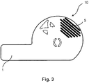
- Fig. 3 shows the contact protection of the Fig. 1 and 2 from above or in a top view.
- a corrugated surface of the handle portion 5 is arranged on this side of the Berstoffschutz.
- the handle portion 5 thus has a structure or surface structure, which allows a non-slip holding the handle portion, for example as a ring, knobs, tab, etc.
- the handle portion 5 may have for better gripping any known in the prior art embodiment. However, such a configuration or surface structure is again provided only optionally.
- the user removes or releases the touch guard 10 from the cartridge 60 prior to loading the cartridge into a fluid treatment device.
- Fig. 4 shows a perspective view of the contact protection device 10 with a view to the in use of a cartridge 60 side facing.
- Fig. 5 shows a perspective view of the contact protection device 10 of the preceding figures, connected to a cassette 60 according to the invention.
- the contact protection device has, as shown, a plate-shaped cover device 1, which covers exactly one connection point 41 completely.
- the contact protection device is, for example, T-shaped and covers two or more connection points simultaneously. Also, any other shapes than those shown here are provided according to the invention.
- FIG Fig. 5 When the shock protection device 10 is connected to the cartridge 60, as shown in FIG Fig. 5 is shown in the Fig. 5 only schematically indicated connecting portion 2, for example, in a centering or holding opening of the cartridge 60, not shown, provided for their centering or holding in a fluid treatment device (not connected to the Berstoffgebervorraum 10 opening 42 of this kind is shown on the left edge of the cassette 60).
- the cassette 60 can not be attached to the fluid treatment apparatus in this state because the centering opening is not freely accessible. However, since free access to the centering opening is a prerequisite for attaching the cassette 60 to the fluid treatment device, the shock protection device 10 must be deliberately removed.
- the shock protection device 10 may also be configured such that, for example, by its dimensions or its connection to the cassette 60, the cassette 60 with the touch guard 10 attached may be attached to the fluid treatment device, but the door of the device can not be closed, for example the shock protection device 10 is released from the cassette 60. This also serves to ensure that the shock protection device 10 has been reliably removed before use of the cassette 60.
- handle portion 5 protrudes beyond the edge of the cassette 60 to facilitate removal of the touch guard 10 from the user.
Landscapes
- Health & Medical Sciences (AREA)
- Heart & Thoracic Surgery (AREA)
- Vascular Medicine (AREA)
- Biomedical Technology (AREA)
- Engineering & Computer Science (AREA)
- Anesthesiology (AREA)
- Cardiology (AREA)
- Hematology (AREA)
- Life Sciences & Earth Sciences (AREA)
- Animal Behavior & Ethology (AREA)
- General Health & Medical Sciences (AREA)
- Public Health (AREA)
- Veterinary Medicine (AREA)
- External Artificial Organs (AREA)
- Infusion, Injection, And Reservoir Apparatuses (AREA)
Description
- Die vorliegende Erfindung betrifft eine medizinische fluidführende Blutkassette (kurz: Kassette) gemäß Anspruch 1 mit einer Berührschutzvorrichtung zum Abdecken einer Konnektionsstelle der Blutkassette für eine medizinische Fluidbehandlung, beispielsweise zum Abdecken einer Substituatstelle der Blutkassette wie sie in Dialysegeräten verwendet werden kann.
- Eine medizinische, fluidführende Blutkassette wird z.B. in
US 2008/093246 (A1 ) beschrieben. - Bei der Handhabung von fluidführenden Kassetten, beispielsweise von Blutkassetten, durch das medizinische Personal besteht stets die Gefahr, dass beim Auspacken einer Kassette aus der Sterilverpackung versehentlich Konnektionsstellen, welche während der Behandlung des Patienten zur Zugabe eines Fluids in die Kassette (kurz: Fluidzugabestellen der Kassette) genutzt wird, mit dem Finger oder einem Gegenstand berührt und somit kontaminiert werden. Aus der Praxis sind bereits verschiedene Lösungen hierfür bekannt, zum Beispiel in Form von lösbar verklebten Schutzfolien.
- Eine Aufgabe der vorliegenden Erfindung ist es, eine weitere medizinische fluidführende Blutkassette mit Berührschutzvorrichtung zum Abdecken einer Konnektionsstelle der Blutkassette für eine medizinische Fluidbehandlung vorzuschlagen.
- Die erfindungsgemäße Aufgabe wird durch eine medizinische fluidführende Blutkassette mit einer Berührschutzvorrichtung mit den Merkmalen des Anspruchs 1 gelöst.
- Die Erfindung betrifft eine medizinische fluidführende Blutkassette mit wenigstens einer Berührschutzvorrichtung gemäß Anspruch 1.
- Die Berührschutzvorrichtung zum Abdecken einer Konnektionsstelle einer medizinischen fluidführenden Kassette für eine medizinische Fluidbehandlung weist wenigstens eine Abdeckeinrichtung zum Abdecken der Konnektionsstelle vor Gebrauch der Kassette, d. h. bevor die Kassette an einer Fluidbehandlungsvorrichtung angebracht wird, auf. Sie weist ferner wenigstens einen Verbindungsabschnitt zum lösbaren Verbinden oder Halten der Berührschutzvorrichtung an der Kassette auf.
- Die wenigstens eine Abdeckeinrichtung der Berührschutzvorrichtung ist über wenigstens eine Konnektionsstelle einer fluidführenden Kassette platzierbar und breit genug, um diese Konnektionsstelle, oder mehrere Konnektionsstellen, der Kassette derart abzudecken, dass bei aufgesetzter Berührschutzvorrichtung bei üblichem Gebrauch kein Abschnitt der Konnektionsstelle durch Berührung mit den Fingern kontaminiert werden kann. Die Abdeckeinrichtung kann alle dem Stand der Technik bekannten Formen haben, beispielsweise kann sie plattenförmig sein. Sie kann rechteckig, halbrund oder dergleichen ausgestaltet sein, usw. Die Größe der Abdeckeinrichtung kann in Abhängigkeit zur Größe der im Einzelfall zu schützenden Konnektionsstelle ausgewählt sein.
- Vorteilhafte Weiterentwicklungen der vorliegenden Erfindung sind jeweils Gegenstand von Unteransprüchen und Ausführungsformen.
- Bei allen folgenden Ausführungen ist der Gebrauch des Ausdrucks "kann sein" bzw. "kann haben" usw. synonym zu "ist vorzugsweise" bzw. "hat vorzugsweise" usw. zu verstehen und soll erfindungsgemäße Ausführungsformen erläutern.
- Erfindungsgemäße Ausführungsformen können eines oder mehrere der im Folgenden genannten Merkmale aufweisen.
- Die Abdeckeinrichtung wird in manchen erfindungsgemäßen Ausführungsformen mittels - insbesondere ausschließlich - Spannung oder Materialsteifigkeit an der Kassette gehalten. Zwischen der Abdeckeinrichtung und der Kassette besteht in diesen Ausführungsformen keine stoffschlüssige Verbindung.
- In bestimmten erfindungsgemäßen Ausführungsformen ist die Berührschutzvorrichtung ausgestaltet und/oder verbunden, um zerstörungsfrei von der Kassette abnehmbar zu sein. Die Berührschutzvorrichtung wird in einigen erfindungsgemäßen Ausführungsformen mittels eines Verbindungsabschnitts an der Kassette gehalten. Der Verbindungsabschnitt sorgt für eine lösbare und stabile Verbindung der Berührschutzvorrichtung an der Kassette. Diese Verbindung kann klebstofffrei erfolgen. Sie kann ein Einrasten, Arretieren, Einbringen, Einklemmen, Einschrauben, ein Halten mittels physikalischer Kräfte oder eine sonstige aus dem Stand der Technik bekannte Art des lösbaren Verbindens sein.
- Die Berührschutzvorrichtung ist in manchen erfindungsgemäßen Ausführungsformen ausgestaltet, um beliebig oft mit der Kassette verbindbar und wieder lösbar zu sein.
- In gewissen Ausführungsformen ist die erfindungsgemäße Berührschutzvorrichtung plattenförmig. In manchen erfindungsgemäßen Ausführungsformen ist die Berührschutzvorrichtung einteilig oder einstückig. Es ist aber für den Fachmann erkennbar, dass die Berührschutzvorrichtung sowohl jede beliebige aus dem Stand der Technik bekannte Form haben kann, um ihre Funktion zu erfüllen, als auch ein- oder mehrstückig oder -teilig gefertigt werden kann.
- In manchen erfindungsgemäßen Ausführungsformen wird die Berührschutzvorrichtung allein durch den Verbindungsabschnitt an der Kassette gehalten.
- In manchen erfindungsgemäßen Ausführungsformen weist die Berührschutzvorrichtung wenigstens eine Kodierstruktur zum formbedingt kodierten Anordnen der Berührschutzvorrichtung an der fluidführenden Kassette auf. Das kodierte Anordnen kann zu einer stabilen Verbindung der Berührschutzvorrichtung an der Kassette beitragen. Hierzu hat die Kodierstruktur eine Form, die beispielsweise mit der Form oder Kontur eines Randes (oder eines anderen Abschnitts) der Kassette korreliert oder sich mit diesem ergänzt oder komplementär zu diesem ist. Das bewirkt einerseits, dass die Verbindung zwischen der Berührschutzvorrichtung und der im Randbereich ebenfalls in der Form der Kodierstruktur verlaufenden Kassette stabil ist. So kann die Kodierstruktur beispielsweise das Verrutschen der Berührschutzvorrichtung oder deren Verdrehen um die Achse ihrer Verbindung mit der Kassette, beispielsweise um den Verbindungsabschnitt, verhindern. Andererseits kann die Kodierstruktur vorteilhaft verhindern, dass die Berührschutzvorrichtung während des Herstellungsprozesses in einer anderen Position zur Kassette als der beabsichtigten an der Kassette angebracht wird. Somit kann ein für den beabsichtigten Berührschutz unwirksames Anbringen der Berührschutzvorrichtung vorteilhaft verhindert werden.
- In einigen erfindungsgemäßen Ausführungsformen ist die Kodierstruktur der Berührschutzvorrichtung wellenförmig oder weist einen wellenförmigen Abschnitt auf. Es ist für den Fachmann erkennbar, dass die Kodierstruktur jede erdenkliche Form aufweisen kann, mit welcher sie wenigstens eine der o. g. Funktionen oder Vorteile erfüllen kann. Beispielsweise kann sie eine gerade Linie, ein Zickzackmuster oder sonstiges gestuftes Muster aufweisen. Sie kann ein kontinuierliches oder ein nicht-kontinuierliches Muster aufweisen, usw.
- In gewissen erfindungsgemäßen Ausführungsformen ist die Kodierstruktur der Berührschutzvorrichtung eine zu diesem Zweck vorgesehene Aussparung in wenigstens einem Abschnitt oder auf einer Seite der Berührschutzvorrichtung.
- In manchen erfindungsgemäßen Ausführungsformen weist die Berührschutzvorrichtung wenigstens eine Fixierungseinrichtung zum lösbaren Aufnehmen, Begrenzen oder Fixieren von Zu- und/oder Ablaufschläuchen der fluidführenden Kassette auf.
- Hierzu hält die Fixierungseinrichtung die Schläuche in einigen erfindungsgemäßen Ausführungsformen in einer gewünschten Stellung relativ zur Kassette. Die Fixierungseinrichtung kann so die Beschädigung der Schläuche durch Abknicken oder deren Kontamination durch ungewolltes Lösen der Schläuche von der Kassette verhindern.
- In bestimmten erfindungsgemäßen Ausführungsformen ist die Fixierungseinrichtung mehrteilig ausgeführt. Zwischen den einzelnen Abschnitten der mehrteiligen Fixierungseinrichtung können weitere Gegenstände wie beispielsweise Schlauchklemmen, welche wiederum mit den vorgenannten Schläuchen verbunden sein können, vorübergehend mittels Reibhaftung oder Rastwirkung gehalten werden. Dies kann einem Schutz der Gegenstände wenigstens bis zum Gebrauch der Kassette dienen.
- In einigen erfindungsgemäßen Ausführungsformen des Berührschutzes ist die Fixierungseinrichtung auf nur einer Seite der Berührschutzvorrichtung angeordnet. Dabei erstreckt sie sich nur auf eine Seite.
- In manchen erfindungsgemäßen Ausführungsformen weist die Berührschutzvorrichtung eine vollständig ebene oder ausschließlich ebene Fläche auf. Diese Fläche ist im Gebrauch der Berührschutzvorrichtung der Konnektionsstelle abgewandt. Die ebene Fläche verhindert vor dem Gebrauch der Kassette vorteilhaft ein ungewolltes Verhaken der Berührschutzvorrichtung mit anderen Gegenständen oder ihr Hängenbleiben an diesen, wodurch die Berührschutzvorrichtung unbeabsichtigt von der Kassette gelöst werden könnte.
- In gewissen erfindungsgemäßen Ausführungsformen weist die Berührschutzvorrichtung wenigstens einen Griffabschnitt zum Greifen der Schutzvorrichtung auf, um die Berührschutzvorrichtung mit der Hand von der fluidführenden Kassette zu lösen. Mittels des Griffabschnitts entfernt oder löst der Benutzer die Berührschutzvorrichtung von der Kassette vor dem Einlegen der Kassette in eine Fluidbehandlungsvorrichtung.
- Der Griffabschnitt kann jede dem Stand der Technik bekannte Ausgestaltung aufweisen, insbesondere eine solche, welche ein rutschsicheres Halten oder Greifen des Griffabschnittes erleichtert oder ermöglicht. Beispielsweise kann der Griffabschnitt als Ring, Noppen, Lasche usw. ausgestaltet sein oder eine Riffelung oder raue Oberfläche aufweisen.
- In manchen erfindungsgemäßen Ausführungsformen der Berührschutzvorrichtung liegt die Abdeckeinrichtung nicht auf dem Griffabschnitt vor, sondern auf einem anderen Abschnitt der Berührschutzvorrichtung. Das bewirkt, dass die Abdeckeinrichtung nicht angefasst werden muss, um die Berührschutzvorrichtung von der Kassette zu lösen. Es minimiert somit die Gefahr der versehentlichen Kontamination während des Lösens der Berührschutzvorrichtung.
- In bestimmten Ausführungsformen der erfindungsgemäßen Berührschutzvorrichtung liegt der Griffabschnitt auf einem der Abdeckeinrichtung entgegengesetzten Abschnitt der Berührschutzvorrichtung vor. Dies kann zu einem kontaminationslosen Lösen der Berührschutzvorrichtung von der Kassette beitragen.
- In manchen erfindungsgemäßen Ausführungsformen der medizinischen fluidführenden Kassette ist die Berührschutzvorrichtung klebstofffrei mit der Kassette verbunden.
- In einigen erfindungsgemäßen Ausführungsformen weist die Berührschutzvorrichtung einen Abschnitt auf, welcher über einen Rand der Kassette hinausragt.
- In manchen erfindungsgemäßen Ausführungsformen ist der Griffabschnitt der Berührschutzvorrichtung auf dem über den Rand der Kassette hinausragenden Abschnitt angeordnet, um dem Benutzer das Entfernen der Berührschutzvorrichtung von der Kassette zu erleichtern.
- In gewissen erfindungsgemäßen Ausführungsformen der Berührschutzvorrichtung ist deren Verbindungsabschnitt in wenigstens eine Halteöffnung oder eine Zentrieröffnung der Kassette eingebracht, um die Berührschutzvorrichtung - ggf. ausschließlich hierdurch - mit der Kassette zu verbinden. Diese Halteöffnung oder Zentrieröffnung der Kassette kann vorgesehen sein, um mit einer Zentrier- oder Halteeinrichtung einer Fluidbehandlungsvorrichtung verbunden zu werden. Sie dient beispielsweise dem Halten oder Zentrieren der Kassette an der Fluidbehandlungsvorrichtung im Gebrauch, beispielsweise während einer Dialysebehandlung.
- In manchen erfindungsgemäßen Ausführungsformen verhindert der Verbindungsabschnitt der Berührschutzvorrichtung im Gebrauch das Anbringen der Kassette an einer Fluidbehandlungsvorrichtung oder das Einlegen der Kassette hierin. Dies wird beispielsweise dadurch erreicht, dass, wenn die Berührschutzvorrichtung mit der Kassette verbunden ist, der Verbindungsabschnitt in der Zentrieröffnung oder Halteöffnung der Kassette steckt. Da die Kassette mit aufgesetzter Berührschutzvorrichtung nicht an der Fluidbehandlungsvorrichtung angebracht werden kann, weil ihre Zentrieröffnung nicht frei liegt, muss die Berührschutzvorrichtung vorher bewusst entfernt werden.
- In weiteren erfindungsgemäßen Ausführungsformen ist die Berührschutzvorrichtung derart ausgestaltet, beispielsweise durch ihre Dimensionen oder ihre Art der Verbindung mit der Kassette, dass die Kassette mit aufgesetzter Berührschutzvorrichtung zwar an der Fluidbehandlungsvorrichtung angebracht werden kann, jedoch etwa eine Abdeckung, oder beispielsweise eine Maschinentür der Vorrichtung, nicht geschlossen werden kann, ohne dass zuvor die Berührschutzvorrichtung von der Kassette gelöst wird. Auch dies dient dazu sicherzustellen, dass die Berührschutzvorrichtung vor Gebrauch der Kassette zuverlässig entfernt wird.
- In einigen vorteilhaften erfindungsgemäßen Ausführungsformen ist die Berührschutzvorrichtung zusammen mit der Kassette sterilisiert. Das Sterilisationsverfahren der Kassette findet in diesen Ausführungsformen mit aufgesetzter Berührschutzvorrichtung statt. Dies ist erfindungsgemäß möglich, da in solchen Ausführungsformen zwischen der Abdeckeinrichtung der Berührschutzvorrichtung - in ihrem über der Konnektionsstelle angeordneten Zustand - und der Kassette und/oder der Konnektionsstelle keine stoffschlüssige oder dampfundurchlässige Verbindung besteht. Somit wird die Dampfdurchgängigkeit der Berührschutzvorrichtung sichergestellt. Die Konnektionsstelle kann selbst bei aufgesetzter Berührschutzvorrichtung bzw. Abdeckeinrichtung erfolgreich sterilisiert werden, beispielsweise mit Heißdampf.
- Dieser Vorteil kann sich auch ergeben, wenn Berührschutzeinrichtung und Kassette aus demselben Material oder aus ähnlichen Materialien sind, jedenfalls aus Materialien, welche mit demselben Sterilisationsverfahren, mit welchem auch die Kassette sterilisierbar ist, sterilisiert werden können.
- In manchen erfindungsgemäßen Ausführungsformen ist die wenigstens eine Konnektionsstelle, welche mittels der Abdeckeinrichtung abgedeckt ist oder wird, eine Verbindungsstelle für eine Substituatleitung.
- In einer weiteren erfindungsgemäßen Ausführungsform ist die medizinische fluidführende Kassette als Blutkassette, beispielsweise für die Dialysebehandlung, insbesondere zur Hämodialyse, zur Hämofiltration, zur Hämodiafiltration, zur Peritonealdialyse, zur Akutdialyse, usw. ausgestaltet.
- Manche oder alle erfindungsgemäßen Ausführungsformen können einen, mehrere oder alle der oben und/oder im Folgenden genannten Vorteile aufweisen.
- Vorteilhaft ist das Lösen der Berührschutzvorrichtung ohne nennenswerte Kraftanwendung aufgrund der o. g. Ausgestaltung der Berührschutzvorrichtung möglich.
- In einigen vorteilhaften Ausführungsformen besteht ein vermindertes Risiko der unbeabsichtigten Kontamination der Konnektionsstelle der Kassette, etwa durch Berühren mit der Hand, da der Griffabschnitt der Berührschutzvorrichtung ausreichend weit von der Abdeckeinrichtung beabstandet ist.
- Die Berührschutzvorrichtung ist in vorteilhaften Ausführungsformen aus demselben Material wie die Kassette gefertigt. Somit kann die Berührschutzvorrichtung denselben Sterilisationsverfahren wie die Kassette unterzogen werden. Zudem kann sie auf die gleiche Weise wie die Kassette oder gemeinsam mit dieser entsorgt werden.
- Das Lösen der Berührschutzvorrichtung von der Kassette kann in vorteilhaften Ausführungsformen einhändig erfolgen.
- In bestimmten erfindungsgemäßen Ausführungsformen weist die Berührschutzvorrichtung entsprechend weiche oder flexible Materialien oder gerundete Kanten derart auf, dass eine Verletzungsgefahr für den Benutzer während ihrer Betätigung, sowie die Gefahr der Beschädigung anderer Bestandteile der Berührschutzvorrichtung oder der Kassette durch beispielsweise scharfe Konturen minimiert sind.
- Durch den möglichen Verzicht auf die Verwendung von Klebstoff zum Anbringen der Berührschutzvorrichtung an der Kassette können bei ihrem Lösen von der Kassette keine Klebstoffreste an der Kassette verbleiben und ggf. über die Konnektionsstelle mit in das Kassetteninnere gelangen.
- Anders als z. B. bei der Verwendung von Sterilitätskappen besteht erfindungsgemäß keine Gefahr des versehentlichen Berührens der Konnektionsstelle beim Auspacken der Kassette.
- Anders als bei Schutzfolien und Sterilitätskappen kann die Berührschutzvorrichtung beim Sterilisieren der Kassette aufgesetzt sein. Ein separates Sterilisieren von Berührschutzvorrichtung und Kassette mit anschließendem Zusammenfügen ist vorteilhaft nicht erforderlich.
- Die vorliegende Erfindung wird im Folgenden anhand der beigefügten Zeichnung, in welcher gleiche Bezugszeichen gleiche oder ähnliche Bauteile bezeichnen, exemplarisch erläutert. In den Figuren gilt:
- Fig. 1
- zeigt die Berührschutzvorrichtung von unten, mit Blick auf ihre im Gebrauch zur fluidführenden Kassette hin gewandte Seite;
- Fig. 2
- zeigt eine seitliche Darstellung der Berührschutzvorrichtung in einem Schnitt entlang der gestrichelten Linie aus
Fig. 1 ; - Fig. 3
- zeigt eine Draufsicht auf die Berührschutzvorrichtung der
Fig. 1 , auf ihre im Gebrauch von der fluidführenden Kassette abgewandte Seite; - Fig. 4
- zeigt die Berührschutzvorrichtung der vorangegangenen Figuren in perspektivischer Darstellung mit Blick auf die in
Fig. 1 gezeigte Unterseite; und - Fig. 5
- zeigt eine perspektivische Darstellung der Berührschutzvorrichtung der vorangegangenen Figuren im Gebrauch an einer erfindungsgemäßen fluidführenden Blutkassette.
-
Fig. 1 zeigt eine mögliche Ausgestaltung der Berührschutzvorrichtung 10. Die Berührschutzvorrichtung 10 weist eine Abdeckeinrichtung 1, einen Verbindungsabschnitt 2, eine Kodierstruktur 3, eine Fixierungseinrichtung 4 und einen Griffabschnitt 5 auf. - Dabei ist die Berührschutzvorrichtung 10 hier beispielhaft als großflächige Platte oder Scheibe mit einem breiteren Abschnitt, welcher den Verbindungsabschnitt 2 zur Verbindung der Berührschutzvorrichtung 10 trägt, und einem schmaleren Abschnitt, welcher im Gebrauch als Abdeckeinrichtung 1 eine in
Fig. 1 nicht gezeigte Konnektionsstelle 41 (sieheFig. 5 ) abdeckt, dargestellt. Die Abdeckeinrichtung 1 ist breit genug, um die Konnektionsstelle 41 einer fluidführenden Kassette 60 (inFig. 1 nicht dargestellt, siehe aberFig. 5 ), mittels welcher eine Fluidverbindung zur Kassette hergestellt werden kann, komplett abzudecken. Mittels der Abdeckeinrichtung 1 wird somit ein unbeabsichtigtes Berühren der Konnektionsstelle 41 der Kassette 60 vor deren Gebrauch, d. h. vor dem Anbringen der Kassette 60 an einer Fluidbehandlungsvorrichtung, verhindert. Mittels der Abdeckeinrichtung 1 wird ein unbeabsichtigtes Berühren der Konnektionsstelle 41 auch noch während des Entfernens der Berührschutzvorrichtung 10 verhindert. - Die Abdeckeinrichtung 1 wird mittels Spannung oder über die Materialsteifigkeit der Berührschutzvorrichtung 10 an der Kassette 60 gehalten. Die Berührschutzvorrichtung 10 wird wiederum mittels des Verbindungsabschnitts 2 an der Kassette 60 gehalten.
- Der Verbindungsschnitt 2 sorgt für eine lösbare und stabile Verbindung der Berührschutzvorrichtung 10 an der Kassette 60. Diese Verbindung ist klebstofffrei und kann ein Einrasten, Arretieren, Einbringen, Einklemmen, Einschrauben oder eine sonstige aus dem Stand der Technik bekannte Art des lösbaren Verbindens sein. Der Verbindungsabschnitt 2 ist in
Fig. 2 eine Einsteck- oder Rastverbindung. - In einigen erfindungsgemäßen Ausführungsformen wird die Berührschutzvorrichtung 10 allein durch den Verbindungsabschnitt 2 an der Kassette 60 gehalten, wie dies auch in den Figuren gezeigt ist. Zwischen der Abdeckeinrichtung 1 und der Kassette 60 besteht in manchen erfindungsgemäßen Ausführungsformen keine stoffschlüssige Verbindung.
- Die Kodierstruktur 3 trägt zu einer stabilen Verbindung der Berührschutzvorrichtung 10 an der Kassette 60 bei.
- Die Kodierstruktur 3 hat eine Form, die mit der Form oder Kontur eines Randes oder eines Abschnitts der Kassette 60 korreliert oder sich mit diesem ergänzt oder komplementär zu diesem ist. Die Kodierstruktur 3 ist im gezeigten Ausführungsbeispiel wellenförmig. Dies bewirkt einerseits, dass die Verbindung zwischen Berührschutzvorrichtung 10 und der im Randbereich ebenfalls wellenförmig verlaufenden Kassette 60 stabil ist, d. h. es verhindert beispielsweise das Verrutschen der Berührschutzvorrichtung 10 oder ihr Verdrehen um die Achse ihre Verbindung mit der Kassette 60, hier um den Verbindungsabschnitt 2. Andererseits verhindert die Kodierstruktur 3, dass die Berührschutzvorrichtung 10 während des Herstellungsprozesses in einer anderen Position als beabsichtigt an der Kassette 60 angebracht wird. Somit kann ein für den Berührschutz unwirksames Anbringen der Berührschutzvorrichtung 10 vorteilhaft verhindert werden.
- Die Fixierungseinrichtung 4 der Berührschutzvorrichtung 10 ist optional vorgesehen. Sie dient, falls vorhanden, zum lösbaren Aufnehmen beispielsweise von Zu- und Ablaufschläuchen. Die Fixierungseinrichtung 4 hält die Schläuche in einer gewünschten Stellung zur Kassette 60. Sie kann so die Beschädigung der Schläuche durch Abknicken oder deren Kontamination durch ungewolltes Lösen der Schläuche von der Kassette 60 verhindern.
- In
Fig. 1 ist die Fixierungseinrichtung 4 dreiteilig ausgeführt. Zwischen den einzelnen der - beispielsweise drei - Abschnitte können weitere Gegenstände wie Schlauchklemmen vorübergehend mittels Reibhaftung gehalten werden. Dies kann einem Schutz der Gegenstände bis zum Gebrauch der Kassette 60 dienen. -
Fig. 2 zeigt die Berührschutzvorrichtung 10 in einem Schnitt entlang der gestrichelten Linie x - x ausFig. 1 von der Seite. Die Fixierungseinrichtung 4 ist hier turmartig ausgestaltet. - In der hier dargestellten Ausführungsform der Berührschutzvorrichtung 10 ist die Fixierungseinrichtung 4 auf nur einer Seite der Berührschutzeinrichtung 10 angeordnet. Die Berührschutzvorrichtung 10 weist in der hier dargestellten Ausführungsform auf einer Seite weder Abschnitte des Verbindungsabschnitts 2, der Kodierstruktur 3 noch der Fixiereinrichtung 4 auf. In einigen erfindungsgemäßen Ausführungsformen weist die Berührschutzvorrichtung 10 auf einer Seite (Ober- oder Unterseite) überhaupt keine erhabenen Strukturen auf.
-
Fig. 3 zeigt die Berührschutzvorrichtung derFig. 1 und 2 von oben oder in einer Draufsicht. Auf dieser Seite der Berührschutzeinrichtung 10 ist eine geriffelte Fläche des Griffabschnitts 5 angeordnet. Der Griffabschnitt 5 weist damit eine Struktur oder Oberflächenstruktur auf, welche ein rutschsicheres Halten des Griffabschnitts ermöglicht, beispielsweise als Ring, Noppen, Lasche etc. Der Griffabschnitt 5 kann zu seinem besseren Greifen jede dem Stand der Technik bekannte Ausgestaltung haben. Eine derartige Ausgestaltung oder Oberflächenstruktur ist allerdings wiederum nur optional vorgesehen. - Mittels des Griffabschnitts 5 entfernt oder löst der Benutzer die Berührschutzvorrichtung 10 von der Kassette 60 vor dem Einlegen der Kassette in eine Fluidbehandlungsvorrichtung.
- Nur strichliniert sind der Verbindungsabschnitt 2 und die Fixiereinrichtung 4 angedeutet. Diese erstrecken sich nicht auf die in
Fig. 3 betrachtete Seite der Berührschutzvorrichtung 10. -
Fig. 4 zeigt eine perspektivische Darstellung der Berührschutzvorrichtung 10 mit Blick auf die im Gebrauch einer Kassette 60 zugewandte Seite. -
Fig. 5 zeigt in perspektivischer Darstellung die Berührschutzvorrichtung 10 der vorangegangenen Figuren, verbunden mit einer erfindungsgemäßen Kassette 60. - Eine mögliche Ausgestaltung der Berührschutzvorrichtung weist, wie abgebildet, eine plattenförmige Abdeckeinrichtung 1 auf, welche genau eine Konnektionsstelle 41 komplett abdeckt. In anderen erfindungsgemäßen Ausführungsformen ist die Berührschutzvorrichtung beispielsweise T-förmig und deckt zwei oder mehr Konnektionsstellen gleichzeitig ab. Auch andere beliebige Formen als die hier gezeigte sind erfindungsgemäß vorgesehen.
- Wenn die Berührschutzvorrichtung 10 mit der Kassette 60 verbunden ist, wie dies in
Fig. 5 gezeigt ist, steckt der inFig. 5 nur zeichnerisch angedeutete Verbindungsabschnitt 2 beispielsweise in einer nicht dargestellten Zentrieröffnung oder Halteöffnung der Kassette 60, vorgesehen zu ihrem Zentrieren oder Halten in einer Fluidbehandlungsvorrichtung (eine nicht mit der Berührschutzvorrichtung 10 verbundene Öffnung 42 dieser Art ist am linken Rand der Kassette 60 gezeigt). Die Kassette 60 kann in diesem Zustand nicht an der Fluidbehandlungsvorrichtung angebracht werden, da die Zentrieröffnung nicht frei zugänglich liegt. Da allerdings ein freier Zugang zur Zentrieröffnung Voraussetzung für das Anbringen der Kassette 60 an der Fluidbehandlungsvorrichtung ist, muss die Berührschutzvorrichtung 10 bewusst entfernt werden. - Die Berührschutzvorrichtung 10 kann auch derart ausgestaltet sein, beispielsweise durch ihre Dimensionen oder ihre Art der Verbindung zur Kassette 60, dass die Kassette 60 mit aufgesetzter Berührschutzvorrichtung 10 zwar an der Fluidbehandlungsvorrichtung angebracht werden kann, jedoch etwa die Tür der Vorrichtung nicht geschlossen werden kann, bevor die Berührschutzvorrichtung 10 von der Kassette 60 gelöst wird. Auch dies dient dazu sicherzustellen, dass die Berührschutzvorrichtung 10 vor Gebrauch der Kassette 60 zuverlässig entfernt wurde.
- Das Lösen der Berührschutzvorrichtung 10 erfolgt ohne nennenswerte Kraftanwendung. Es erfolgt ferner unter vermindertem Risiko der unbeabsichtigten Kontamination der Konnektionsstelle 41 der Kassette 60, etwa durch Berühren mit der Hand, da der Griffabschnitt 5 der Berührschutzvorrichtung 10 von der Abdeckeinrichtung 1 beabstandet ist.
- Ferner ragt der Griffabschnitt 5 über den Rand der Kassette 60 hinaus, um dem Benutzer das Entfernen der Berührschutzvorrichtung 10 zu erleichtern.
-
- 10
- Berührschutzvorrichtung
- 1
- Abdeckeinrichtung
- 2
- Verbindungsabschnitt
- 3
- Kodierstruktur
- 4
- Fixierungseinrichtung
- 5
- Griffabschnitt
- 41
- Konnektionsstelle
- 42
- Zentrieröffnung oder Halteöffnung
- 60
- fluidführende Kassette
Claims (14)
- Medizinische fluidführende Blutkassette (60) für eine medizinische Fluidbehandlung mit wenigstens einer Konnektionsstelle (41) und wenigstens einer Berührschutzvorrichtung (10) zum Abdecken der Konnektionsstelle (41) der medizinischen fluidführenden Kassette (60), wobei die Berührschutzvorrichtung (10) wenigstens eine Abdeckeinrichtung (1) zum Abdecken der Konnektionsstelle (41) vor Gebrauch der Kassette (60), und wenigstens einen Verbindungsabschnitt (2) zum lösbaren Verbinden mit oder Halten der Berührschutzvorrichtung (10) an der Kassette (60) aufweist,
wobei die Verbindung mittels Verbindungsabschnitt (2) mittels Einrasten oder Einklemmen erfolgt;
dadurch gekennzeichnet, dass der Verbindungsabschnitt (2) der
Berührschutzvorrichtung (10) diese mit einer Halteöffnung oder einer Zentrieröffnung (42) der Kassette (60) für deren Aufnahme an einer Blutbehandlungsvorrichtung verbindet; und
dass zwischen der Abdeckeinrichtung (1) der Berührschutzvorrichtung (10) in ihrem über der Konnektionsstelle (41) angeordneten Zustand und der Konnektionsstelle (41) keine stoffschlüssige Verbindung besteht. - Blutkassette (60) nach Anspruch 1, wobei die Berührschutzvorrichtung (10) wenigstens eine Kodierstruktur (3) zum formbedingt kodierten Anordnen der Berührschutzvorrichtung (10) an der fluidführenden Kassette (60) aufweist.
- Blutkassette (60) nach einem der vorangegangenen Ansprüche, wobei die Berührschutzvorrichtung (10) wenigstens eine Fixierungseinrichtung (4) zum lösbaren Aufnehmen oder Halten von Zu- und/oder Ablaufschläuchen der fluidführenden Kassette (60) aufweist.
- Blutkassette (60) nach Anspruch 3, wobei die Fixierungseinrichtung (4) auf nur einer Seite der Berührschutzvorrichtung (10) angeordnet ist.
- Blutkassette (60) nach einem der vorangegangenen Ansprüche, wobei die Berührschutzvorrichtung (10) wenigstens einen Griffabschnitt (5) zum Greifen der Berührschutzvorrichtung (10) aufweist, um diese von der fluidführenden Blutkassette (60) zu lösen.
- Blutkassette (60) nach Anspruch 5, wobei die Abdeckeinrichtung (1) nicht auf dem Griffabschnitt (5) vorliegt.
- Blutkassette (60) nach einem der vorangegangenen Ansprüche, wobei die Berührschutzvorrichtung (10) einteilig hergestellt ist.
- Blutkassette (60) nach einem der vorangegangenen Ansprüche, wobei die Berührschutzvorrichtung (10) klebstofffrei mit der Blutkassette (60) verbunden ist.
- Blutkassette (60) nach einem der vorangegangenen Ansprüche, wobei die Berührschutzvorrichtung (10) einen Abschnitt aufweist, welcher über einen Rand der Blutkassette (60) hinausragt.
- Blutkassette (60) nach einem der vorangegangenen Ansprüche, wobei der Griffabschnitt (5) der Berührschutzvorrichtung (10) auf dem über den Rand der Blutkassette (60) hinausragenden Abschnitt angeordnet ist.
- Blutkassette (60) nach einem der vorangegangenen Ansprüche, wobei der Verbindungsabschnitt (2) der Berührschutzvorrichtung (10) im Gebrauch das Anbringen der Blutkassette (60) an einer Blutbehandlungsvorrichtung oder das Schließen einer Abdeckung mechanisch verhindert.
- Blutkassette (60) nach einem der vorangegangenen Ansprüche, wobei die Berührschutzvorrichtung (10) zusammen mit der Blutkassette (60) sterilisiert ist.
- Blutkassette (60) nach einem der vorangegangenen Ansprüche, mit einer Randkontur, welche entsprechend einer Kontur der Kodierstruktur (3) der Berührschutzvorrichtung (10) ausgestaltet ist.
- Blutkassette (60) nach einem der vorangegangenen Ansprüche, wobei wenigstens eine Konnektionsstelle (41) eine Verbindungsstelle für eine Substituatleitung ist.
Applications Claiming Priority (3)
| Application Number | Priority Date | Filing Date | Title |
|---|---|---|---|
| US201161512952P | 2011-07-29 | 2011-07-29 | |
| DE102011108781A DE102011108781A1 (de) | 2011-07-29 | 2011-07-29 | Berührschutzvorrichtung für medizinische fluidführende Kassette und Kassette |
| PCT/EP2012/003189 WO2013017235A1 (de) | 2011-07-29 | 2012-07-27 | Berührschutzvorrichtung für medizinische fluidführende kassette und kassette |
Publications (2)
| Publication Number | Publication Date |
|---|---|
| EP2736562A1 EP2736562A1 (de) | 2014-06-04 |
| EP2736562B1 true EP2736562B1 (de) | 2016-06-08 |
Family
ID=47503056
Family Applications (1)
| Application Number | Title | Priority Date | Filing Date |
|---|---|---|---|
| EP12745626.7A Active EP2736562B1 (de) | 2011-07-29 | 2012-07-27 | Berührschutzvorrichtung für medizinische fluidführende kassette und kassette |
Country Status (4)
| Country | Link |
|---|---|
| US (1) | US9700665B2 (de) |
| EP (1) | EP2736562B1 (de) |
| DE (1) | DE102011108781A1 (de) |
| WO (1) | WO2013017235A1 (de) |
Cited By (1)
| Publication number | Priority date | Publication date | Assignee | Title |
|---|---|---|---|---|
| EP3354295A1 (de) | 2017-01-30 | 2018-08-01 | Fresenius Medical Care Deutschland GmbH | Medizinische fluidleitende kassette mit kontaktschutz |
Families Citing this family (9)
| Publication number | Priority date | Publication date | Assignee | Title |
|---|---|---|---|---|
| JP6049685B2 (ja) | 2011-03-23 | 2016-12-21 | ネクステージ メディカル インコーポレイテッド | 腹膜透析使い捨てユニット、コントローラ、腹膜透析システム |
| US9861733B2 (en) | 2012-03-23 | 2018-01-09 | Nxstage Medical Inc. | Peritoneal dialysis systems, devices, and methods |
| DE102014102598A1 (de) * | 2014-02-27 | 2015-08-27 | Fresenius Medical Care Deutschland Gmbh | Blutbehandlungskassette mit Sterilisationsöffnung und zugehörigem Verschluss sowie Blutbehandlungsvorrichtung |
| CA169480S (en) * | 2016-01-15 | 2017-11-24 | Fresenius Medical Care Deutschland Gmbh | Dialysis machine |
| DE102016006089A1 (de) * | 2016-05-20 | 2017-11-23 | Fresenius Medical Care Deutschland Gmbh | Externe Funktionseinrichtung |
| DE102017101730A1 (de) * | 2017-01-30 | 2018-08-02 | Fresenius Medical Care Deutschland Gmbh | Neue Berührschutzvorrichtung für medizinische fluidführende Kassette und Kassette |
| WO2018237375A1 (en) | 2017-06-24 | 2018-12-27 | Nxstage Medical, Inc. | Peritoneal dialysis fluid preparation and/or treatment devices methods and systems |
| CA3092575A1 (en) | 2018-02-28 | 2019-09-06 | Nxstage Medical, Inc. | Fluid preparation and treatment devices, methods, and systems |
| JP7597485B2 (ja) * | 2020-12-22 | 2024-12-10 | 旭化成メディカル株式会社 | 計量チャンバー及び液体処理装置 |
Family Cites Families (8)
| Publication number | Priority date | Publication date | Assignee | Title |
|---|---|---|---|---|
| US4304672A (en) * | 1978-04-04 | 1981-12-08 | Sbr Lab, Inc. | Stored blood and liquid system pH control method and apparatus |
| US5441636A (en) * | 1993-02-12 | 1995-08-15 | Cobe Laboratories, Inc. | Integrated blood treatment fluid module |
| DE19814695C2 (de) * | 1998-04-01 | 2001-09-13 | Fresenius Medical Care De Gmbh | Kassette zur Förderung von Flüssigkeiten, insbesondere Dialyseflüssigkeiten, Dialysegerät und Verfahren zum Fördern, Bilanzieren, Dosieren und Beheizen eines medizinischen Fluids |
| DE19828650C2 (de) | 1998-06-26 | 2000-10-19 | Fresenius Medical Care De Gmbh | Konnektorelement mit integriertem Absperrelement |
| FR2881116A1 (fr) * | 2005-01-21 | 2006-07-28 | Gambro Lundia Ab | Dispositif de conditionnement pour article medical |
| WO2009094184A1 (en) * | 2008-01-23 | 2009-07-30 | Deka Products Limited Partnership | Fluid volume determination for medical treatment system |
| KR101753134B1 (ko) * | 2009-04-23 | 2017-07-03 | 프레제니우스 메디칼 케어 도이칠란드 게엠베하 | 외부 기능 장치, 이 외부 기능 장치를 수용하기 위한 혈액 처리 장치 및 방법 |
| US8617465B2 (en) | 2009-09-15 | 2013-12-31 | Baxter International Inc. | Dialysis connector and cap compatible with gas sterilization |
-
2011
- 2011-07-29 DE DE102011108781A patent/DE102011108781A1/de not_active Ceased
-
2012
- 2012-07-27 EP EP12745626.7A patent/EP2736562B1/de active Active
- 2012-07-27 US US13/559,948 patent/US9700665B2/en active Active
- 2012-07-27 WO PCT/EP2012/003189 patent/WO2013017235A1/de not_active Ceased
Cited By (1)
| Publication number | Priority date | Publication date | Assignee | Title |
|---|---|---|---|---|
| EP3354295A1 (de) | 2017-01-30 | 2018-08-01 | Fresenius Medical Care Deutschland GmbH | Medizinische fluidleitende kassette mit kontaktschutz |
Also Published As
| Publication number | Publication date |
|---|---|
| US20130030404A1 (en) | 2013-01-31 |
| WO2013017235A1 (de) | 2013-02-07 |
| DE102011108781A1 (de) | 2013-01-31 |
| US9700665B2 (en) | 2017-07-11 |
| EP2736562A1 (de) | 2014-06-04 |
Similar Documents
| Publication | Publication Date | Title |
|---|---|---|
| DE102011108781A1 (de) | Berührschutzvorrichtung für medizinische fluidführende Kassette und Kassette | |
| DE69513357T2 (de) | Schwenkbare Nadelschutzvorrichtung | |
| EP1562667A1 (de) | Einführhilfe zum einführen einer kanüle eines katheterkopfes in ein organisches gewebe | |
| DE69629498T2 (de) | Vorrichtung mit einziehbarer chirurgischer klinge | |
| EP2618854B1 (de) | Sterilbehälter | |
| EP2288395A2 (de) | Organizer zum lösbaren aufnehmen von komponenten von blutschlauchsätzen und verfahren zum herstellen sowie zum vorbereiten desselben | |
| DE3717526A1 (de) | Katheterhaltevorrichtung und verfahren zu ihrer herstellung | |
| EP3170518B1 (de) | Dialysemaschine mit integrierter dialysatorkupplung | |
| WO2010121821A1 (de) | Haltevorrichtung zum halten einer externen funktionseinrichtung an einer behandlungsvorrichtung, externe funktionseinrichtung sowie behandlungsvorrichtung | |
| WO2020049042A1 (de) | Verpackung mit einer haltevorrichtung zum halten eines medizintechnischen werkzeugs | |
| EP3024531A1 (de) | Sterile schlauchabdeckung für ein medizinisches schlauchleitungssystem | |
| DE69834745T2 (de) | Universelle patrone | |
| DE102019123806A1 (de) | Medizinischer Konnektor mit automatischer Abdichtung bei der Dekonnektion | |
| DE3210964A1 (de) | Sterile verschluss- und kupplungseinheit | |
| EP3866721B1 (de) | Resorbierbare verpackung für ein medizintechnisches produkt | |
| DE20020326U1 (de) | Medizinisches Klebeband zur Lagefixierung von Infusionskanülen | |
| DE102016013394A1 (de) | Schutzüberzug für ein Teil eines Medizingeräts | |
| CA3034862C (en) | System and method for ergonomic needle protector | |
| DE102017101730A1 (de) | Neue Berührschutzvorrichtung für medizinische fluidführende Kassette und Kassette | |
| EP4464346B1 (de) | Fixiervorrichtung zum fixieren eines katheters | |
| DE202009010095U1 (de) | Verbindungsvorrichtung für einen auswechselbaren, abgeschlossenen Sekret-Absaugkatheter | |
| DE102009024448A1 (de) | Haltevorrichtung zum Halten einer externen Funktionseinrichtung an einer Behandlungsvorrichtung, externe Funktionseinrichtung sowie Behandlungsvorrichtung | |
| DE10059519B4 (de) | Medizinisches Klebeband zur Lagefixierung von Infusionskanülen | |
| DE102018108087A1 (de) | Verpackung mit einem in einer separaten Haltevorrichtung befindlichen medizintechnischen Arbeitsende | |
| DE102022107751A1 (de) | Medizinische Werkzeugspitze, Betätigungsvorrichtung, chirurgisches Instrument und Befestigungsverfahren |
Legal Events
| Date | Code | Title | Description |
|---|---|---|---|
| PUAI | Public reference made under article 153(3) epc to a published international application that has entered the european phase |
Free format text: ORIGINAL CODE: 0009012 |
|
| 17P | Request for examination filed |
Effective date: 20140228 |
|
| AK | Designated contracting states |
Kind code of ref document: A1 Designated state(s): AL AT BE BG CH CY CZ DE DK EE ES FI FR GB GR HR HU IE IS IT LI LT LU LV MC MK MT NL NO PL PT RO RS SE SI SK SM TR |
|
| 17Q | First examination report despatched |
Effective date: 20141217 |
|
| GRAP | Despatch of communication of intention to grant a patent |
Free format text: ORIGINAL CODE: EPIDOSNIGR1 |
|
| INTG | Intention to grant announced |
Effective date: 20150729 |
|
| GRAS | Grant fee paid |
Free format text: ORIGINAL CODE: EPIDOSNIGR3 |
|
| INTG | Intention to grant announced |
Effective date: 20151218 |
|
| GRAA | (expected) grant |
Free format text: ORIGINAL CODE: 0009210 |
|
| AK | Designated contracting states |
Kind code of ref document: B1 Designated state(s): AL AT BE BG CH CY CZ DE DK EE ES FI FR GB GR HR HU IE IS IT LI LT LU LV MC MK MT NL NO PL PT RO RS SE SI SK SM TR |
|
| REG | Reference to a national code |
Ref country code: GB Ref legal event code: FG4D Free format text: NOT ENGLISH |
|
| REG | Reference to a national code |
Ref country code: CH Ref legal event code: EP |
|
| REG | Reference to a national code |
Ref country code: FR Ref legal event code: PLFP Year of fee payment: 5 |
|
| REG | Reference to a national code |
Ref country code: IE Ref legal event code: FG4D Free format text: LANGUAGE OF EP DOCUMENT: GERMAN |
|
| REG | Reference to a national code |
Ref country code: DE Ref legal event code: R096 Ref document number: 502012007369 Country of ref document: DE |
|
| REG | Reference to a national code |
Ref country code: AT Ref legal event code: REF Ref document number: 804757 Country of ref document: AT Kind code of ref document: T Effective date: 20160715 |
|
| REG | Reference to a national code |
Ref country code: LT Ref legal event code: MG4D |
|
| REG | Reference to a national code |
Ref country code: NL Ref legal event code: MP Effective date: 20160608 |
|
| PG25 | Lapsed in a contracting state [announced via postgrant information from national office to epo] |
Ref country code: LT Free format text: LAPSE BECAUSE OF FAILURE TO SUBMIT A TRANSLATION OF THE DESCRIPTION OR TO PAY THE FEE WITHIN THE PRESCRIBED TIME-LIMIT Effective date: 20160608 Ref country code: NO Free format text: LAPSE BECAUSE OF FAILURE TO SUBMIT A TRANSLATION OF THE DESCRIPTION OR TO PAY THE FEE WITHIN THE PRESCRIBED TIME-LIMIT Effective date: 20160908 Ref country code: FI Free format text: LAPSE BECAUSE OF FAILURE TO SUBMIT A TRANSLATION OF THE DESCRIPTION OR TO PAY THE FEE WITHIN THE PRESCRIBED TIME-LIMIT Effective date: 20160608 |
|
| PG25 | Lapsed in a contracting state [announced via postgrant information from national office to epo] |
Ref country code: GR Free format text: LAPSE BECAUSE OF FAILURE TO SUBMIT A TRANSLATION OF THE DESCRIPTION OR TO PAY THE FEE WITHIN THE PRESCRIBED TIME-LIMIT Effective date: 20160909 Ref country code: HR Free format text: LAPSE BECAUSE OF FAILURE TO SUBMIT A TRANSLATION OF THE DESCRIPTION OR TO PAY THE FEE WITHIN THE PRESCRIBED TIME-LIMIT Effective date: 20160608 Ref country code: NL Free format text: LAPSE BECAUSE OF FAILURE TO SUBMIT A TRANSLATION OF THE DESCRIPTION OR TO PAY THE FEE WITHIN THE PRESCRIBED TIME-LIMIT Effective date: 20160608 Ref country code: RS Free format text: LAPSE BECAUSE OF FAILURE TO SUBMIT A TRANSLATION OF THE DESCRIPTION OR TO PAY THE FEE WITHIN THE PRESCRIBED TIME-LIMIT Effective date: 20160608 Ref country code: LV Free format text: LAPSE BECAUSE OF FAILURE TO SUBMIT A TRANSLATION OF THE DESCRIPTION OR TO PAY THE FEE WITHIN THE PRESCRIBED TIME-LIMIT Effective date: 20160608 Ref country code: SE Free format text: LAPSE BECAUSE OF FAILURE TO SUBMIT A TRANSLATION OF THE DESCRIPTION OR TO PAY THE FEE WITHIN THE PRESCRIBED TIME-LIMIT Effective date: 20160608 Ref country code: ES Free format text: LAPSE BECAUSE OF FAILURE TO SUBMIT A TRANSLATION OF THE DESCRIPTION OR TO PAY THE FEE WITHIN THE PRESCRIBED TIME-LIMIT Effective date: 20160608 |
|
| PG25 | Lapsed in a contracting state [announced via postgrant information from national office to epo] |
Ref country code: BE Free format text: LAPSE BECAUSE OF NON-PAYMENT OF DUE FEES Effective date: 20160731 |
|
| PG25 | Lapsed in a contracting state [announced via postgrant information from national office to epo] |
Ref country code: IS Free format text: LAPSE BECAUSE OF FAILURE TO SUBMIT A TRANSLATION OF THE DESCRIPTION OR TO PAY THE FEE WITHIN THE PRESCRIBED TIME-LIMIT Effective date: 20161008 Ref country code: SK Free format text: LAPSE BECAUSE OF FAILURE TO SUBMIT A TRANSLATION OF THE DESCRIPTION OR TO PAY THE FEE WITHIN THE PRESCRIBED TIME-LIMIT Effective date: 20160608 Ref country code: CZ Free format text: LAPSE BECAUSE OF FAILURE TO SUBMIT A TRANSLATION OF THE DESCRIPTION OR TO PAY THE FEE WITHIN THE PRESCRIBED TIME-LIMIT Effective date: 20160608 Ref country code: RO Free format text: LAPSE BECAUSE OF FAILURE TO SUBMIT A TRANSLATION OF THE DESCRIPTION OR TO PAY THE FEE WITHIN THE PRESCRIBED TIME-LIMIT Effective date: 20160608 Ref country code: EE Free format text: LAPSE BECAUSE OF FAILURE TO SUBMIT A TRANSLATION OF THE DESCRIPTION OR TO PAY THE FEE WITHIN THE PRESCRIBED TIME-LIMIT Effective date: 20160608 |
|
| PG25 | Lapsed in a contracting state [announced via postgrant information from national office to epo] |
Ref country code: SM Free format text: LAPSE BECAUSE OF FAILURE TO SUBMIT A TRANSLATION OF THE DESCRIPTION OR TO PAY THE FEE WITHIN THE PRESCRIBED TIME-LIMIT Effective date: 20160608 Ref country code: PL Free format text: LAPSE BECAUSE OF FAILURE TO SUBMIT A TRANSLATION OF THE DESCRIPTION OR TO PAY THE FEE WITHIN THE PRESCRIBED TIME-LIMIT Effective date: 20160608 Ref country code: PT Free format text: LAPSE BECAUSE OF FAILURE TO SUBMIT A TRANSLATION OF THE DESCRIPTION OR TO PAY THE FEE WITHIN THE PRESCRIBED TIME-LIMIT Effective date: 20161010 |
|
| REG | Reference to a national code |
Ref country code: CH Ref legal event code: PL |
|
| REG | Reference to a national code |
Ref country code: DE Ref legal event code: R097 Ref document number: 502012007369 Country of ref document: DE |
|
| PG25 | Lapsed in a contracting state [announced via postgrant information from national office to epo] |
Ref country code: MC Free format text: LAPSE BECAUSE OF FAILURE TO SUBMIT A TRANSLATION OF THE DESCRIPTION OR TO PAY THE FEE WITHIN THE PRESCRIBED TIME-LIMIT Effective date: 20160608 |
|
| PLBE | No opposition filed within time limit |
Free format text: ORIGINAL CODE: 0009261 |
|
| STAA | Information on the status of an ep patent application or granted ep patent |
Free format text: STATUS: NO OPPOSITION FILED WITHIN TIME LIMIT |
|
| PG25 | Lapsed in a contracting state [announced via postgrant information from national office to epo] |
Ref country code: CH Free format text: LAPSE BECAUSE OF NON-PAYMENT OF DUE FEES Effective date: 20160731 Ref country code: LI Free format text: LAPSE BECAUSE OF NON-PAYMENT OF DUE FEES Effective date: 20160731 |
|
| REG | Reference to a national code |
Ref country code: IE Ref legal event code: MM4A |
|
| 26N | No opposition filed |
Effective date: 20170309 |
|
| GBPC | Gb: european patent ceased through non-payment of renewal fee |
Effective date: 20160908 |
|
| PG25 | Lapsed in a contracting state [announced via postgrant information from national office to epo] |
Ref country code: SI Free format text: LAPSE BECAUSE OF FAILURE TO SUBMIT A TRANSLATION OF THE DESCRIPTION OR TO PAY THE FEE WITHIN THE PRESCRIBED TIME-LIMIT Effective date: 20160608 Ref country code: DK Free format text: LAPSE BECAUSE OF FAILURE TO SUBMIT A TRANSLATION OF THE DESCRIPTION OR TO PAY THE FEE WITHIN THE PRESCRIBED TIME-LIMIT Effective date: 20160608 |
|
| REG | Reference to a national code |
Ref country code: FR Ref legal event code: PLFP Year of fee payment: 6 |
|
| PG25 | Lapsed in a contracting state [announced via postgrant information from national office to epo] |
Ref country code: GB Free format text: LAPSE BECAUSE OF NON-PAYMENT OF DUE FEES Effective date: 20160908 Ref country code: IE Free format text: LAPSE BECAUSE OF NON-PAYMENT OF DUE FEES Effective date: 20160727 |
|
| PG25 | Lapsed in a contracting state [announced via postgrant information from national office to epo] |
Ref country code: LU Free format text: LAPSE BECAUSE OF NON-PAYMENT OF DUE FEES Effective date: 20160727 |
|
| PG25 | Lapsed in a contracting state [announced via postgrant information from national office to epo] |
Ref country code: HU Free format text: LAPSE BECAUSE OF FAILURE TO SUBMIT A TRANSLATION OF THE DESCRIPTION OR TO PAY THE FEE WITHIN THE PRESCRIBED TIME-LIMIT; INVALID AB INITIO Effective date: 20120727 Ref country code: CY Free format text: LAPSE BECAUSE OF FAILURE TO SUBMIT A TRANSLATION OF THE DESCRIPTION OR TO PAY THE FEE WITHIN THE PRESCRIBED TIME-LIMIT Effective date: 20160608 |
|
| REG | Reference to a national code |
Ref country code: FR Ref legal event code: PLFP Year of fee payment: 7 |
|
| PG25 | Lapsed in a contracting state [announced via postgrant information from national office to epo] |
Ref country code: MT Free format text: LAPSE BECAUSE OF FAILURE TO SUBMIT A TRANSLATION OF THE DESCRIPTION OR TO PAY THE FEE WITHIN THE PRESCRIBED TIME-LIMIT Effective date: 20160608 Ref country code: MK Free format text: LAPSE BECAUSE OF FAILURE TO SUBMIT A TRANSLATION OF THE DESCRIPTION OR TO PAY THE FEE WITHIN THE PRESCRIBED TIME-LIMIT Effective date: 20160608 |
|
| PG25 | Lapsed in a contracting state [announced via postgrant information from national office to epo] |
Ref country code: BG Free format text: LAPSE BECAUSE OF FAILURE TO SUBMIT A TRANSLATION OF THE DESCRIPTION OR TO PAY THE FEE WITHIN THE PRESCRIBED TIME-LIMIT Effective date: 20160608 |
|
| REG | Reference to a national code |
Ref country code: AT Ref legal event code: MM01 Ref document number: 804757 Country of ref document: AT Kind code of ref document: T Effective date: 20170727 |
|
| PG25 | Lapsed in a contracting state [announced via postgrant information from national office to epo] |
Ref country code: TR Free format text: LAPSE BECAUSE OF FAILURE TO SUBMIT A TRANSLATION OF THE DESCRIPTION OR TO PAY THE FEE WITHIN THE PRESCRIBED TIME-LIMIT Effective date: 20160608 Ref country code: AL Free format text: LAPSE BECAUSE OF FAILURE TO SUBMIT A TRANSLATION OF THE DESCRIPTION OR TO PAY THE FEE WITHIN THE PRESCRIBED TIME-LIMIT Effective date: 20160608 |
|
| PG25 | Lapsed in a contracting state [announced via postgrant information from national office to epo] |
Ref country code: AT Free format text: LAPSE BECAUSE OF NON-PAYMENT OF DUE FEES Effective date: 20170727 |
|
| P01 | Opt-out of the competence of the unified patent court (upc) registered |
Effective date: 20230602 |
|
| PGFP | Annual fee paid to national office [announced via postgrant information from national office to epo] |
Ref country code: DE Payment date: 20250620 Year of fee payment: 14 |
|
| PGFP | Annual fee paid to national office [announced via postgrant information from national office to epo] |
Ref country code: IT Payment date: 20260618 Year of fee payment: 15 |
|
| PGFP | Annual fee paid to national office [announced via postgrant information from national office to epo] |
Ref country code: FR Payment date: 20260618 Year of fee payment: 15 |