EP2736133A1 - Wire harness - Google Patents
Wire harness Download PDFInfo
- Publication number
- EP2736133A1 EP2736133A1 EP12814390.6A EP12814390A EP2736133A1 EP 2736133 A1 EP2736133 A1 EP 2736133A1 EP 12814390 A EP12814390 A EP 12814390A EP 2736133 A1 EP2736133 A1 EP 2736133A1
- Authority
- EP
- European Patent Office
- Prior art keywords
- wire harness
- corrugated tube
- central axis
- exterior member
- width
- Prior art date
- Legal status (The legal status is an assumption and is not a legal conclusion. Google has not performed a legal analysis and makes no representation as to the accuracy of the status listed.)
- Granted
Links
Images


Classifications
-
- B—PERFORMING OPERATIONS; TRANSPORTING
- B60—VEHICLES IN GENERAL
- B60R—VEHICLES, VEHICLE FITTINGS, OR VEHICLE PARTS, NOT OTHERWISE PROVIDED FOR
- B60R16/00—Electric or fluid circuits specially adapted for vehicles and not otherwise provided for; Arrangement of elements of electric or fluid circuits specially adapted for vehicles and not otherwise provided for
- B60R16/02—Electric or fluid circuits specially adapted for vehicles and not otherwise provided for; Arrangement of elements of electric or fluid circuits specially adapted for vehicles and not otherwise provided for electric constitutive elements
- B60R16/0207—Wire harnesses
- B60R16/0215—Protecting, fastening and routing means therefor
-
- H—ELECTRICITY
- H01—ELECTRIC ELEMENTS
- H01B—CABLES; CONDUCTORS; INSULATORS; SELECTION OF MATERIALS FOR THEIR CONDUCTIVE, INSULATING OR DIELECTRIC PROPERTIES
- H01B7/00—Insulated conductors or cables characterised by their form
- H01B7/0045—Cable-harnesses
-
- H—ELECTRICITY
- H01—ELECTRIC ELEMENTS
- H01B—CABLES; CONDUCTORS; INSULATORS; SELECTION OF MATERIALS FOR THEIR CONDUCTIVE, INSULATING OR DIELECTRIC PROPERTIES
- H01B7/00—Insulated conductors or cables characterised by their form
- H01B7/04—Flexible cables, conductors, or cords, e.g. trailing cables
-
- H—ELECTRICITY
- H02—GENERATION; CONVERSION OR DISTRIBUTION OF ELECTRIC POWER
- H02G—INSTALLATION OF ELECTRIC CABLES OR LINES, OR OF COMBINED OPTICAL AND ELECTRIC CABLES OR LINES
- H02G3/00—Installations of electric cables or lines or protective tubing therefor in or on buildings, equivalent structures or vehicles
- H02G3/02—Details
- H02G3/04—Protective tubing or conduits, e.g. cable ladders or cable troughs
- H02G3/0406—Details thereof
-
- H—ELECTRICITY
- H02—GENERATION; CONVERSION OR DISTRIBUTION OF ELECTRIC POWER
- H02G—INSTALLATION OF ELECTRIC CABLES OR LINES, OR OF COMBINED OPTICAL AND ELECTRIC CABLES OR LINES
- H02G3/00—Installations of electric cables or lines or protective tubing therefor in or on buildings, equivalent structures or vehicles
- H02G3/02—Details
- H02G3/04—Protective tubing or conduits, e.g. cable ladders or cable troughs
- H02G3/0462—Tubings, i.e. having a closed section
- H02G3/0468—Corrugated
-
- F—MECHANICAL ENGINEERING; LIGHTING; HEATING; WEAPONS; BLASTING
- F16—ENGINEERING ELEMENTS AND UNITS; GENERAL MEASURES FOR PRODUCING AND MAINTAINING EFFECTIVE FUNCTIONING OF MACHINES OR INSTALLATIONS; THERMAL INSULATION IN GENERAL
- F16L—PIPES; JOINTS OR FITTINGS FOR PIPES; SUPPORTS FOR PIPES, CABLES OR PROTECTIVE TUBING; MEANS FOR THERMAL INSULATION IN GENERAL
- F16L11/00—Hoses, i.e. flexible pipes
- F16L11/24—Hoses, i.e. flexible pipes wound from strips or bands
Definitions
- the present invention relates to a wire harness.
- a wire harness disclosed in the following patent document 1 includes three high voltage electric wires, and three metal protecting pipes for accommodating and protecting the three high voltage electric wires respectively.
- the high voltage electric wires connect a motor which is carried in the front of a vehicle and an inverter which is carried in the middle of the vehicle or at the rear side of the vehicle.
- the high voltage electric wires are wired from a battery in the middle of the vehicle or at the rear side of the vehicle to the motor in the front of the vehicle through the bottom of a vehicle body floor which is the outer side of a vehicle frame.
- a stone splash or a water splash may occur to the high voltage electric wires which are wired through the bottom of the vehicle body floor in this way.
- the high voltage electric wires are covered by metal protecting pipes to be protected from a stone splash or a water splash.
- the metal protecting pipe has a function of preventing the high voltage electric wire from a stone splash or a water splash and a function to protect the high voltage electric wire from being bended due to the stiffness of the metal protecting pipe.
- the metal protecting pipe has an electromagnetic shielding function because the metal protecting pipe is made of metal.
- a wire harness is manufactured by inserting the three high voltage electric wires into the metal protecting pipes which are straight, respectively, and bending the metal protecting pipes along the wiring route of the wire harness under the vehicle body floor. After the wire harness is manufactured as above in the factory of a harness manufacturer, the wire harness is conveyed to an assembly factory of a vehicle manufacturer. Then the wire harness is assembled to a predetermined position of a vehicle. Thereby, the wiring of the wire harness is completed.
- Patent document 1 JP-A-2004-224156
- a protector When the flexible pipe bodies are used, to assemble the pipe bodies to a predetermined position of a vehicle, for example, a protector is necessary. Because the protector is a resin molded member which matches with the wiring route, the protector becomes an exclusive member/exclusive design for each vehicle. Thereby, the versatility is decreased and the cost is increased.
- the protector provided under the vehicle floor approaches the ground and troubles may occur.
- the present invention is made in view of the above problems, and the object of the present invention is to provide a wire harness for which an exterior member can be maintained in a desired shape.
- the wire harnesses of the present invention are characterized in the following (1) to (4).
- wire harness according to one embodiment of the present invention is described with reference to the figures as follows.
- Fig. 1 is a schematic view which shows an example when the wire harness according to one embodiment of the present invention is wired in a hybrid vehicle.
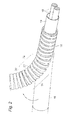
- Fig. 2 is an appearance perspective view which shows a state after the wire harness is bended from a straight state.
- Fig. 3 is an appearance perspective view which shows that a route keeping tape is wound around a bent part of the wire harness.
- Fig. 4A is a longitudinal sectional view of the wire harness before a corrugated tube is bended
- Fig. 4B is a longitudinal sectional view of the wire harness after the corrugated tube is bended.
- Fig. 5 is an illustrative view to describe the extensibility of the route keeping tape.
- Fig. 1 is a schematic view which shows an example when the wire harness according to one embodiment of the present invention is wired in a hybrid vehicle.
- Fig. 2 is an appearance perspective view which shows a state after the wire harness is bended from a straight state.
- Fig. 3 is an appearance
- FIG. 6A is a figure which shows an example of the cross-section of the convex parts and the concave parts of the corrugated tube
- Fig. 6B is a figure which shows another example
- Fig. 6C is a figure which shows an example of the cross-section of the convex parts and the concave parts of a traditional corrugated tube.
- a hybrid vehicle 1 is a vehicle which is driven by mixing two powers of an engine 2 and a motor unit 3.
- the electric power from a battery 5 (battery pack) is supplied to the motor unit 3 via an inverter unit 4.
- the engine 2, the motor unit 3 and the inverter unit 4 are carried in an engine room 6 at the position of the front wheels and the like.
- the battery 5 is carried in a vehicle rear part 7 of rear wheels and the like (the battery 5 may be carried in an indoor space behind the engine room 6).
- the motor unit 3 and the inverter unit 4 are connected by a well-known high voltage wire harness 8.
- the battery 5 and the inverter unit 4 are connected by a high voltage wire harness 9 according to the present embodiment.
- the wire harness 9 and the battery 5 are connected through a junction block 12 which the battery 5 is provided with.
- a rear end 13 of the wire harness 9 is connected to the junction block 12 with a connector.
- the side of the wire harness 9 at the rear end 13 is wired above the floor at the indoor side of the vehicle.
- the side of the wire harness 9 at a front end 14 is also wired above the floor.
- the side of the wire harness 9 at a front end 14 is connected to the inverter unit 4 with a connector.
- a middle part 10, which is located between the front end 14 and the rear end 13, of the wire harness 9 is wired below a vehicle body floor 11.
- the motor unit 3 includes a motor (not shown in the figure) and a generator (not shown in the figure) in construction.
- the inverter unit 4 includes an inverter (not shown in the figure) and a converter (not shown in the figure) in construction.
- the motor unit 3 is formed as a motor assembly including a shielding case (not shown in the figure).
- the inverter unit 4 is also formed as an inverter assembly including a shielding case.
- the battery 5 is a Ni-MH battery or Li-ion battery, and is modularized. An electricity accumulating device such as a capacitor may be used.
- the battery 5 is not particularly limited to the construction according to the present embodiment as long as the battery 5 may be used for the hybrid vehicle 1 or an electric vehicle.
- a structure of the wire harness 9 is described below in detail with reference to Figs. 2 to 5 .
- the wire harness 9 includes two electric wires 18, an electromagnetic shielding member 19 which collectively covers the two electric wires 18, and a corrugated tube 16 which is provided at the outer side of the electromagnetic shielding member 19 to cover the electromagnetic shielding member 19 and functions as an exterior member.
- the electric wire 18 is a conductive path which includes a conductor and an insulator, and is formed to have a length that is necessary for electrical connection. Connectors are provided respectively at the two ends of the electric wire 18, one end is connected to the connector of the junction block 12 (refer to Fig. 1 ) and the other end is connected to the connector of the inverter unit 4 (refer to Fig. 1 ), respectively.
- the conductor is manufactured of copper, copper alloy, aluminum or aluminum alloy.
- the conductor may be either a conductor structure in which strands are twisted or a rod-like conductor structure whose cross section is a rectangular shape or a round shape (for example, a conductor structure with a rectangular single core or a round single core, and in this case, the electric wire itself becomes rod-like).
- two electric wires 18 are used as the conductive paths, but the number of the electric wires 18 is not limited, and the conductive path is also not limited to electric wires.
- the electromagnetic shielding member 19 is intended to prevent electrical signals transmitted through the electric wires 18 from being affected by the electromagnetic wave from the outside, and the electromagnetic shielding member 19 is formed of a shielding member containing a conductive metal foil or a metal foil alone into a pipe-like shape.
- the electromagnetic shielding member 19 is formed to have about the same length as the full length of the two electric wires 18.
- the electromagnetic shielding member 19 contains a metal foil in this embodiment, but the present invention is not limited to this. That is, as long as the electromagnetic wave can be dealt with, for example, a web which has a number of extra-fine strands may be used as the electromagnetic shielding member 19. In this case, the web has conductivity and is formed into a pipe-like shape.
- the corrugated tube 16 is a bendable tubular exterior member (tube body) which has flexibility, and is a resin/metal tube (bellow tube) which has convex parts and concave parts (ridges and valleys) which are formed continuously on the outer peripheral surface along the longitudinal direction of the electric wire 18. That is, as shown in Fig. 4A , the corrugated tube 16 is formed with the convex parts and the concave parts, which extend in the peripheral direction, alternately along the longitudinal direction. The top surfaces of the convex parts are formed on a peripheral surface which extends in parallel to the central axis of the corrugated tube 16 in a cross section in parallel to the central axis.
- the corrugated tube 16 of the present embodiment is a resin article which has a circular cross section, but the present invention is not limited to the circular cross section, an oval cross section, quadrangular cross section or the like is also possible.
- bent part 20A to change the direction of the wire harness 9 in the vehicle indoor room to the inverter unit 4
- bent part 20B to change the direction of the wire harness 9 from below the vehicle body floor 11 to the vehicle indoor room
- bent part 20C to change the direction of the wire harness 9 from the vehicle indoor room to below the vehicle body floor 11.
- the bent part 20 is a bent part of the wire harness 9, and is also a bent part of the corrugated tube 16 at the same time.
- a number 21 at the bent part 20 shows an outer side part which has a larger R (curvature).
- a number 22 shows an inner side part which has a smaller R.
- a number 23 shows a side part which is a part that connects the outer side part 21 and the inner side part 22.
- a route keeping tape 17 is wound helically around the bent part 20 in a longitudinal direction of the corrugated tube 16 to maintain the bended shape of the bent part 20.
- the route keeping tape 17 is used to maintain the bended shape of the corrugated tube 16 by being wound around the corrugated tube 16. Therefore, the route keeping tape 17 is processed (for example, oriented) so that the route keeping tape 17 cannot extend or buckle (fold) to a degree of almost having no deformation in the widthwise direction (a Z direction in Fig. 5 ). The route keeping tape 17 is so formed that the route keeping tape 17 is more difficult to extend or buckle in the widthwise direction than the corrugated tube 16. Since the details of the above-described process is well known, the description is omitted herein.
- a metal foil tape, a hard resin tape or the like can be used as the route keeping tape 17.
- an aluminum foil tape, a stainless steel tape or the like is preferred to be used as the metal foil tape, but the material is not limited to these.
- Plating may be performed as needed.
- Adhesive is applied to one side surface of the metal foil tape.
- a polycarbonate sheet (of a tape shape), an acrylic sheet (of a tape shape) or the like can be used as the hard resin tape, but the material is not limited to these.
- Adhesive is applied to one side surface of the hard resin tape.
- an interval between a ridge (convex part) 33 and a ridge 33 adjacent to the ridge 33 at the upper side of the corrugated tube 16 (a pitch A1) is equal to an interval between a ridge (convex part) 31 and a ridge 31 adjacent to the ridge 31 at the lower side of the corrugated tube 16 (a pitch A1).
- an interval between the ridge 33 and the adjacent ridge 33 at the outer side part 21 of the corrugated tube 16 becomes larger than the pitch A1.
- an interval between the ridge 31 and the adjacent ridge 31 at the inner side part 22 of the corrugated tube 16 becomes smaller than the pitch A1. That is, the corrugated tube 16 expands at the outer side part 21 in the longitudinal direction and contracts at the inner side part 22 in the longitudinal direction.
- a force which makes the corrugated tube 16 return to a state before the corrugated tube 16 is bended (a restoring force) is applied, and the corrugated tube 16 returns to the original state shown in Fig. 4A . That is, the wire harness 9 returns to a straight line shape, and is not maintained in the bended shape.
- the route keeping tape 17 is wound helically around the bent part 20 along the longitudinal direction of the corrugated tube 16 to fix the interval between the ridges 33, 33 arranged to be adjacent to each other (a width A2 in Fig. 4B ) and the interval between the ridges 31, 31 arranged to be adjacent to each other (a width A3 in Fig. 4B ).
- the route keeping tape 17 is so formed that the width of the route keeping tape 17 in the central axis direction of the corrugated tube 16 is longer than the width of the bottom surfaces which define the valleys (concave parts) in the central axis direction.
- the route keeping tape 17 is wound around the corrugated tube 16 in the longitudinal direction to cover the valleys 32, 32 arranged to be adjacent to each other and to cover the valleys 34, 34 arranged to be adjacent to each other (refer to Fig. 3 ).
- the route keeping tape 17 which is more difficult to extend or buckle in the widthwise direction than the corrugated tube 16 is wound around the corrugated tube 16 to fix the interval between the ridges 33, 33 arranged to be adjacent to each other and the interval between the ridges 31, 31 arranged to be adjacent to each other, the width A2 at the outer side part 21 is difficult to return to the width A1. Further, the width A3 at the inner side part 22 is difficult to return to the width A1. Therefore, the interval between the ridges 33, 33 arranged to be adjacent to each other at the outer side part 21 and the interval between the ridges 31, 31 arranged to be adjacent to each other at the inner side part 22 can be maintained constant, respectively. Therefore, the maintenance of the bended state of the bent part 20 of the corrugated tube 16 (route maintenance) can be performed surely.
- the shapes of the ridges and valleys of the corrugated tube are preferable, for example, as those shown in Figs. 6A and 6B .
- letters S show ridges (convex parts) and letters T show valleys (concave parts).
- the shape of a traditional corrugated tube 66 in which ridges 71 and valleys 72 alternate continuously is a shape which has curved top parts, as shown in Fig. 6C . Therefore, when the route keeping tape 17 is wound around the corrugated tube 66 by the above-described method, the areas where the route keeping tape 17 is attached to two ridges 71 adjacent to a valley 72 are limited to the areas close to the tops of the ridges 71.
- this pitch a is the same over the full length of the wire harness.
- the width of the ridge 61 can be increased. That is, the wire harness 9 according to the present embodiment is so formed that for the corrugated tube 56, the width of the top surface of the ridge (the convex part) 61 in the central axis direction is longer than the width of the bottom surface which defines the valley (the concave part) 62 in the central axis direction. Therefore, the areas where the route keeping tape 17 is attached to the ridges 61 become larger than before. Therefore, the route holding force of the wire harness 9 can be improved.
- the route keeping tape 17 can maintain the bended shape of the bent part 20 by being wound around the bent part 20 along the longitudinal direction as described above.
- the wire harness 9 of the present embodiment not only a flexible corrugated tube is simply provided as an exterior member of the conductive path, but the corrugated tube may be maintained in a desired shape.
- a low cost, versatile wire harness for which a protector is not necessary can be provided. That is, for the wire harness 9 according to the present embodiment, since standard components (replaceable components) such as, the corrugated tube and the route keeping tape are used as substitutes for the resin molded protector, there is no need for vehicle exclusive components or metal molds. Therefore, the manufacturing cost of the wire harness can be reduced. Since the route keeping tape is used instead of a protector, the weight can be reduced and design modification can be easy to perform.
- the route keeping tape 17 in the embodiment described above is difficult to extend or buckle in the widthwise direction, but the route keeping tape 17 may slightly extend in the longitudinal direction.
- the wire harness according to the present invention is useful in that a route keeping tape is used for an exterior member instead of a protector and a desired shape of the exterior member is maintained.
Landscapes
- Engineering & Computer Science (AREA)
- Architecture (AREA)
- Civil Engineering (AREA)
- Structural Engineering (AREA)
- Mechanical Engineering (AREA)
- Details Of Indoor Wiring (AREA)
- Installation Of Indoor Wiring (AREA)
- Insulated Conductors (AREA)
Abstract


Description
- The present invention relates to a wire harness.
- A wire harness disclosed in the following patent document 1 includes three high voltage electric wires, and three metal protecting pipes for accommodating and protecting the three high voltage electric wires respectively.
- The high voltage electric wires connect a motor which is carried in the front of a vehicle and an inverter which is carried in the middle of the vehicle or at the rear side of the vehicle. The high voltage electric wires are wired from a battery in the middle of the vehicle or at the rear side of the vehicle to the motor in the front of the vehicle through the bottom of a vehicle body floor which is the outer side of a vehicle frame.
- A stone splash or a water splash may occur to the high voltage electric wires which are wired through the bottom of the vehicle body floor in this way. The high voltage electric wires are covered by metal protecting pipes to be protected from a stone splash or a water splash. The metal protecting pipe has a function of preventing the high voltage electric wire from a stone splash or a water splash and a function to protect the high voltage electric wire from being bended due to the stiffness of the metal protecting pipe. The metal protecting pipe has an electromagnetic shielding function because the metal protecting pipe is made of metal.
- A wire harness is manufactured by inserting the three high voltage electric wires into the metal protecting pipes which are straight, respectively, and bending the metal protecting pipes along the wiring route of the wire harness under the vehicle body floor. After the wire harness is manufactured as above in the factory of a harness manufacturer, the wire harness is conveyed to an assembly factory of a vehicle manufacturer. Then the wire harness is assembled to a predetermined position of a vehicle. Thereby, the wiring of the wire harness is completed.
- Patent document 1:
JP-A-2004-224156 - In the traditional techniques described above, when the wire harness is conveyed, to prevent the metal protecting pipes from contacting each other and being damaged or being deformed, it is necessary to secure an enough space for each of the metal protecting pipes and for each of the wire harnesses. Because the metal protecting pipe is manufactured by being bended three-dimensionally, it is necessary to secure a three-dimensional space.
- In order to solve the above problems, it is considered to replace the metal protecting pipes with flexible pipe bodies. However, the following problems occur when only the flexible pipe bodies are used.
- First, when the flexible pipe bodies are used, it is difficult to maintain a desired shape at the time of assembling and wiring the wire harness and after the wiring.
- When the flexible pipe bodies are used, to assemble the pipe bodies to a predetermined position of a vehicle, for example, a protector is necessary. Because the protector is a resin molded member which matches with the wiring route, the protector becomes an exclusive member/exclusive design for each vehicle. Thereby, the versatility is decreased and the cost is increased.
- Since the metal mold may have to be tried for many times at the development stage when the protector is used, design expense, metal mold expense, design time or the like are spent.
- Because the part where the protector is assembled to a pipe body is upsized when the protector is used, the protector provided under the vehicle floor approaches the ground and troubles may occur.
- The present invention is made in view of the above problems, and the object of the present invention is to provide a wire harness for which an exterior member can be maintained in a desired shape.
- To achieve the previously described object, the wire harnesses of the present invention are characterized in the following (1) to (4).
- (1) A wire harness comprising:
- an exterior member, having a flexibility and tubular shape, and covering at least one conductive path; and
- a route keeping tape which is more difficult to extend and buckle in a widthwise direction than the exterior member,
- wherein the route keeping tape is wound helically around a bent part, which is formed by bending the exterior member, along a longitudinal direction.
For the construction of the above (1), the route keeping tape is wound around so that the shape of the bent part is maintained in a bended shape. Therefore, the exterior member is maintained in a desired shape by using the route keeping tape instead of a protector.
- (2) The wire harness according to the above (1), wherein
the exterior member is formed with convex parts and concave parts, which extend in a peripheral direction, alternately along the longitudinal direction, and
top surfaces of the convex parts are formed to a peripheral surface which extends in parallel to a central axis of the exterior member in a cross section in parallel to the central axis, and a width of the top surfaces of the convex parts in the central axis direction is longer than a width of bottom surfaces which define the concave parts in the central axis direction.
For the construction of the above (2), the area where the exterior member and the route keeping tape contact is large. Therefore, the route keeping tape can be strongly fixed to the exterior member when the route keeping tape and the exterior member are attached together. Thereby, the shape of the bent part is maintained surely. - (3) The wire harness according to the above (2), wherein
a width of the route keeping tape in the central axis direction is longer than the width of the bottom surfaces which define the concave parts in the central axis direction, so that the route keeping tape is wound around the bent part to cover the concave parts.
For the construction of the above (3), the interval between the adjacent convex parts which sandwich the concave part which is covered by the route keeping tape can be maintained surely. - (4) The wire harness according to the above (1), wherein
the exterior member is formed with convex parts and concave parts, which extend in a peripheral direction, alternately along a longitudinal direction,
top surfaces of the concave parts are formed into a plane shape, a rising angle of the convex parts is sharp, and a width of the top surfaces of the convex parts in a central axis direction of the exterior member is long. - For the construction of the above (4), when the bended shape of the bent part is maintained, the interval between the convex parts which are adjacent to each other is fixed surely. Furthermore, the top surfaces of the adjacent convex parts are connected surely by the route keeping tape.
-
-
Fig. 1 is a schematic view which shows an example when the wire harness according to one embodiment of the present invention is wired in a hybrid vehicle. -
Fig. 2 is an appearance perspective view which shows a state after the wire harness is bended from a straight state. -
Fig. 3 is an appearance perspective view which shows that a route keeping tape is wound around a bent part of the wire harness. -
Fig. 4A is a longitudinal sectional view of the wire harness before a corrugated tube is bended, andFig. 4B is a longitudinal sectional view of the wire harness after the corrugated tube is bended. -
Fig. 5 is an illustrative view to describe the extensibility of the route keeping tape. -
Fig. 6A is a figure which shows an example of the cross-section of the convex parts and the concave parts of the corrugated tube,Fig. 6B is a figure which shows another example, andFig. 6C is a figure which shows an example of the cross-section of the convex parts and the concave parts of a traditional corrugated tube. - The wire harness according to one embodiment of the present invention is described with reference to the figures as follows.
-
Fig. 1 is a schematic view which shows an example when the wire harness according to one embodiment of the present invention is wired in a hybrid vehicle.Fig. 2 is an appearance perspective view which shows a state after the wire harness is bended from a straight state.Fig. 3 is an appearance perspective view which shows that a route keeping tape is wound around a bent part of the wire harness.Fig. 4A is a longitudinal sectional view of the wire harness before a corrugated tube is bended, andFig. 4B is a longitudinal sectional view of the wire harness after the corrugated tube is bended.Fig. 5 is an illustrative view to describe the extensibility of the route keeping tape.Fig. 6A is a figure which shows an example of the cross-section of the convex parts and the concave parts of the corrugated tube,Fig. 6B is a figure which shows another example, andFig. 6C is a figure which shows an example of the cross-section of the convex parts and the concave parts of a traditional corrugated tube. - In this embodiment, an example in which the wire harness is applied to a hybrid vehicle (or an electric vehicle) is given and described.
- In
Fig. 1 , a hybrid vehicle 1 is a vehicle which is driven by mixing two powers of anengine 2 and amotor unit 3. The electric power from a battery 5 (battery pack) is supplied to themotor unit 3 via aninverter unit 4. Theengine 2, themotor unit 3 and theinverter unit 4 are carried in anengine room 6 at the position of the front wheels and the like. Thebattery 5 is carried in a vehiclerear part 7 of rear wheels and the like (thebattery 5 may be carried in an indoor space behind the engine room 6). - The
motor unit 3 and theinverter unit 4 are connected by a well-known highvoltage wire harness 8. Thebattery 5 and theinverter unit 4 are connected by a highvoltage wire harness 9 according to the present embodiment. - The
wire harness 9 and thebattery 5 are connected through ajunction block 12 which thebattery 5 is provided with. Arear end 13 of thewire harness 9 is connected to thejunction block 12 with a connector. The side of thewire harness 9 at therear end 13 is wired above the floor at the indoor side of the vehicle. The side of thewire harness 9 at afront end 14 is also wired above the floor. The side of thewire harness 9 at afront end 14 is connected to theinverter unit 4 with a connector. Amiddle part 10, which is located between thefront end 14 and therear end 13, of thewire harness 9 is wired below avehicle body floor 11. - The
motor unit 3 includes a motor (not shown in the figure) and a generator (not shown in the figure) in construction. Theinverter unit 4 includes an inverter (not shown in the figure) and a converter (not shown in the figure) in construction. Themotor unit 3 is formed as a motor assembly including a shielding case (not shown in the figure). Theinverter unit 4 is also formed as an inverter assembly including a shielding case. Thebattery 5 is a Ni-MH battery or Li-ion battery, and is modularized. An electricity accumulating device such as a capacitor may be used. Thebattery 5 is not particularly limited to the construction according to the present embodiment as long as thebattery 5 may be used for the hybrid vehicle 1 or an electric vehicle. - A structure of the
wire harness 9 is described below in detail with reference toFigs. 2 to 5 . - The
wire harness 9 includes twoelectric wires 18, anelectromagnetic shielding member 19 which collectively covers the twoelectric wires 18, and acorrugated tube 16 which is provided at the outer side of theelectromagnetic shielding member 19 to cover theelectromagnetic shielding member 19 and functions as an exterior member. - The
electric wire 18 is a conductive path which includes a conductor and an insulator, and is formed to have a length that is necessary for electrical connection. Connectors are provided respectively at the two ends of theelectric wire 18, one end is connected to the connector of the junction block 12 (refer toFig. 1 ) and the other end is connected to the connector of the inverter unit 4 (refer toFig. 1 ), respectively. The conductor is manufactured of copper, copper alloy, aluminum or aluminum alloy. The conductor may be either a conductor structure in which strands are twisted or a rod-like conductor structure whose cross section is a rectangular shape or a round shape (for example, a conductor structure with a rectangular single core or a round single core, and in this case, the electric wire itself becomes rod-like). In this embodiment, twoelectric wires 18 are used as the conductive paths, but the number of theelectric wires 18 is not limited, and the conductive path is also not limited to electric wires. For example, it is also possible to provide an insulator to a well-known bus bar to be used as a high voltage conductive path, or to use a high voltage coaxial combined conductive path which is constructed by coaxially combining n systems of circuits. - The
electromagnetic shielding member 19 is intended to prevent electrical signals transmitted through theelectric wires 18 from being affected by the electromagnetic wave from the outside, and theelectromagnetic shielding member 19 is formed of a shielding member containing a conductive metal foil or a metal foil alone into a pipe-like shape. Theelectromagnetic shielding member 19 is formed to have about the same length as the full length of the twoelectric wires 18. - The
electromagnetic shielding member 19 contains a metal foil in this embodiment, but the present invention is not limited to this. That is, as long as the electromagnetic wave can be dealt with, for example, a web which has a number of extra-fine strands may be used as theelectromagnetic shielding member 19. In this case, the web has conductivity and is formed into a pipe-like shape. - The
corrugated tube 16 is a bendable tubular exterior member (tube body) which has flexibility, and is a resin/metal tube (bellow tube) which has convex parts and concave parts (ridges and valleys) which are formed continuously on the outer peripheral surface along the longitudinal direction of theelectric wire 18. That is, as shown inFig. 4A , thecorrugated tube 16 is formed with the convex parts and the concave parts, which extend in the peripheral direction, alternately along the longitudinal direction. The top surfaces of the convex parts are formed on a peripheral surface which extends in parallel to the central axis of thecorrugated tube 16 in a cross section in parallel to the central axis. Thecorrugated tube 16 of the present embodiment is a resin article which has a circular cross section, but the present invention is not limited to the circular cross section, an oval cross section, quadrangular cross section or the like is also possible. - With reference to
Fig. 2 again, when thecorrugated tube 16 is bended in the direction shown by the arrow inFig. 2 from a straight state (thecorrugated tube 16 of imaginary lines shown by two-dots dashed lines inFig. 2 ) that theelectromagnetic shielding member 19 which covers theelectric wires 18 is inserted into thecorrugated tube 16, abent part 20 is formed. Thebent part 20, as shown inFig. 1 , is formed at the position of abent part 20A to change the direction of thewire harness 9 in the vehicle indoor room to theinverter unit 4, abent part 20B to change the direction of thewire harness 9 from below thevehicle body floor 11 to the vehicle indoor room, or a bent part 20C to change the direction of thewire harness 9 from the vehicle indoor room to below thevehicle body floor 11. - The
bent part 20 is a bent part of thewire harness 9, and is also a bent part of thecorrugated tube 16 at the same time. Anumber 21 at thebent part 20 shows an outer side part which has a larger R (curvature). Anumber 22 shows an inner side part which has a smaller R. Furthermore, anumber 23 shows a side part which is a part that connects theouter side part 21 and theinner side part 22. - Then, after the
bent part 20 is formed, aroute keeping tape 17 is wound helically around thebent part 20 in a longitudinal direction of thecorrugated tube 16 to maintain the bended shape of thebent part 20. - The principle of maintaining the bended shape of the
bent part 20 by winding theroute keeping tape 17 around thebent part 20 is described below with reference toFigs. 4A to 5 . - The
route keeping tape 17 is used to maintain the bended shape of thecorrugated tube 16 by being wound around thecorrugated tube 16. Therefore, theroute keeping tape 17 is processed (for example, oriented) so that theroute keeping tape 17 cannot extend or buckle (fold) to a degree of almost having no deformation in the widthwise direction (a Z direction inFig. 5 ). Theroute keeping tape 17 is so formed that theroute keeping tape 17 is more difficult to extend or buckle in the widthwise direction than thecorrugated tube 16. Since the details of the above-described process is well known, the description is omitted herein. - A metal foil tape, a hard resin tape or the like can be used as the
route keeping tape 17. For example, an aluminum foil tape, a stainless steel tape or the like is preferred to be used as the metal foil tape, but the material is not limited to these. Plating may be performed as needed. Adhesive is applied to one side surface of the metal foil tape. A polycarbonate sheet (of a tape shape), an acrylic sheet (of a tape shape) or the like can be used as the hard resin tape, but the material is not limited to these. Adhesive is applied to one side surface of the hard resin tape. - Before the
corrugated tube 16 is bended (refer toFig. 4A ), an interval between a ridge (convex part) 33 and aridge 33 adjacent to theridge 33 at the upper side of the corrugated tube 16 (a pitch A1) is equal to an interval between a ridge (convex part) 31 and aridge 31 adjacent to theridge 31 at the lower side of the corrugated tube 16 (a pitch A1). - After the
corrugated tube 16 is bended (refer toFig. 4B ), an interval between theridge 33 and theadjacent ridge 33 at theouter side part 21 of the corrugated tube 16 (a pitch A2) becomes larger than the pitch A1. On the other hand, an interval between theridge 31 and theadjacent ridge 31 at theinner side part 22 of the corrugated tube 16 (a pitch A3) becomes smaller than the pitch A1. That is, thecorrugated tube 16 expands at theouter side part 21 in the longitudinal direction and contracts at theinner side part 22 in the longitudinal direction. - For example, if hands that make the
corrugated tube 16 bended are released, a force which makes thecorrugated tube 16 return to a state before thecorrugated tube 16 is bended (a restoring force) is applied, and thecorrugated tube 16 returns to the original state shown inFig. 4A . That is, thewire harness 9 returns to a straight line shape, and is not maintained in the bended shape. - Thus, in this embodiment, the
route keeping tape 17 is wound helically around thebent part 20 along the longitudinal direction of thecorrugated tube 16 to fix the interval between theridges Fig. 4B ) and the interval between theridges Fig. 4B ). For thewire harness 9 according to the present embodiment, theroute keeping tape 17 is so formed that the width of theroute keeping tape 17 in the central axis direction of thecorrugated tube 16 is longer than the width of the bottom surfaces which define the valleys (concave parts) in the central axis direction. Theroute keeping tape 17 is wound around thecorrugated tube 16 in the longitudinal direction to cover thevalleys valleys Fig. 3 ). - As described above, since the
route keeping tape 17 which is more difficult to extend or buckle in the widthwise direction than thecorrugated tube 16 is wound around thecorrugated tube 16 to fix the interval between theridges ridges outer side part 21 is difficult to return to the width A1. Further, the width A3 at theinner side part 22 is difficult to return to the width A1. Therefore, the interval between theridges outer side part 21 and the interval between theridges inner side part 22 can be maintained constant, respectively. Therefore, the maintenance of the bended state of thebent part 20 of the corrugated tube 16 (route maintenance) can be performed surely. - The shapes of the ridges and valleys of the corrugated tube are preferable, for example, as those shown in
Figs. 6A and 6B . InFigs. 6A to 6C , letters S show ridges (convex parts) and letters T show valleys (concave parts). The shape of a traditionalcorrugated tube 66 in whichridges 71 andvalleys 72 alternate continuously is a shape which has curved top parts, as shown inFig. 6C . Therefore, when theroute keeping tape 17 is wound around thecorrugated tube 66 by the above-described method, the areas where theroute keeping tape 17 is attached to tworidges 71 adjacent to avalley 72 are limited to the areas close to the tops of theridges 71. - In contrast, as shown in
Fig. 6A , whenridges 51 of acorrugated tube 46 have rectangular shapes, since the width of the ridge 51 (the width in the central axis direction of the corrugated tube) is longer than the width of theridge 71 shown inFig. 6C , the areas where theroute keeping tape 17 is attached to theridges 51 become larger. Therefore, the route holding force of thewire harness 9 can be improved. - In a longitudinal section of a
corrugated tube 56, when the distance from the rising edge of aridge 61 to the rising edge of anadjacent valley 62 along the longitudinal direction is measured as a pitch a (refer toFig. 6B ), usually, this pitch a is the same over the full length of the wire harness. - As shown in
Fig. 6B , for thecorrugated tube 56, if the width of theridge 61 is made to be longer than the width of thevalley 62, the width of theridge 61 can be increased. That is, thewire harness 9 according to the present embodiment is so formed that for thecorrugated tube 56, the width of the top surface of the ridge (the convex part) 61 in the central axis direction is longer than the width of the bottom surface which defines the valley (the concave part) 62 in the central axis direction. Therefore, the areas where theroute keeping tape 17 is attached to theridges 61 become larger than before. Therefore, the route holding force of thewire harness 9 can be improved. - As described above, the
route keeping tape 17 can maintain the bended shape of thebent part 20 by being wound around thebent part 20 along the longitudinal direction as described above. According to thewire harness 9 of the present embodiment, not only a flexible corrugated tube is simply provided as an exterior member of the conductive path, but the corrugated tube may be maintained in a desired shape. Further, a low cost, versatile wire harness for which a protector is not necessary can be provided. That is, for thewire harness 9 according to the present embodiment, since standard components (replaceable components) such as, the corrugated tube and the route keeping tape are used as substitutes for the resin molded protector, there is no need for vehicle exclusive components or metal molds. Therefore, the manufacturing cost of the wire harness can be reduced. Since the route keeping tape is used instead of a protector, the weight can be reduced and design modification can be easy to perform. - The features of the embodiment of the wire harness according to the present invention described above are briefly, collectively listed in the following (1) to (4), respectively.
- (1) The
wire harness 9 according to the present embodiment includes the flexible, tubularcorrugated tube 16 which is an exterior member and covers twoelectric wires 18 of at least one conductive path, and theroute keeping tape 17 which is more difficult to extend or buckle in the widthwise direction than thecorrugated tube 16. Theroute keeping tape 17 is wound helically around thebent part 20 which is formed by bending thecorrugated tube 16 in the longitudinal direction of thecorrugated tube 16. - (2) For the
wire harness 9 according to the present embodiment, thecorrugated tube 16 is formed with the convex parts and the concave parts, which extend in the peripheral direction, alternately along the longitudinal direction, and the top surfaces of the convex parts are formed to a peripheral surface which extends in parallel to the central axis of thecorrugated tube 16 in the cross section in parallel to the central axis. The width of the top surfaces of the convex parts in the central axis direction of thecorrugated tube 16 is longer than the width of the bottom surfaces which define the concave parts of thecorrugated tube 16 in the central axis direction. - (3) For the
wire harness 9 according to the present embodiment, the width of theroute keeping tape 17 in the central axis direction is longer than the width of the bottom surfaces which define the concave parts of thecorrugated tube 16 in the central axis direction, so that theroute keeping tape 17 is wound around thebent part 20 to cover the concave parts. - (4) For the
wire harness 9 according to the present embodiment, thecorrugated tube 16 is formed with the convex parts and the concave parts, which extend in the peripheral direction, alternately along the longitudinal direction, the top surfaces of the concave parts are formed into a plane shape, the rising angle of the convex parts becomes sharper, and the width of the top surfaces of the convex parts in the central axis direction of thecorrugated tube 16 becomes longer. - It is apparent that various modifications can be made to the invention without changing the purpose of the invention. For example, the
route keeping tape 17 in the embodiment described above is difficult to extend or buckle in the widthwise direction, but theroute keeping tape 17 may slightly extend in the longitudinal direction. - Although the invention is described in detail with reference to specific embodiments, it is apparent that various modifications and amendments may be made by those skilled in the art without departing from the spirit and scope of the invention.
- This application is based on the Japanese patent application (patent application No.
2011-160134 - The wire harness according to the present invention is useful in that a route keeping tape is used for an exterior member instead of a protector and a desired shape of the exterior member is maintained.
-
- 1
- hybrid vehicle
- 2
- engine
- 3
- motor unit
- 4
- inverter unit
- 5
- battery
- 6
- engine room
- 7
- vehicle rear part
- 8
- high voltage wire harness
- 9
- wire harness
- 10
- middle part
- 11
- vehicle body floor
- 12
- junction block
- 13
- rear end
- 14
- front end
- 16
- corrugated tube (exterior member)
- 17
- route keeping tape
- 18
- electric wire (conductive path)
- 19
- electromagnetic shielding member
- 20
- bent part
- 21
- outer side part
- 22
- inner side part
- 23
- side part
- 46
- corrugated tube (exterior member)
- 56
- corrugated tube (exterior member)
Claims (4)
- A wire harness comprising:an exterior member, having a flexibility and tubular shape, and covering at least one conductive path; anda route keeping tape which is more difficult to extend and buckle in a widthwise direction than the exterior member,wherein the route keeping tape is wound helically around a bent part, which is formed by bending the exterior member, along a longitudinal direction.
- The wire harness according to claim 1, wherein
the exterior member is formed with convex parts and concave parts, which extend in a peripheral direction, alternately along the longitudinal direction, and
top surfaces of the convex parts are formed to a peripheral surface which extends in parallel to a central axis of the exterior member in a cross section in parallel to the central axis, and a width of the top surfaces of the convex parts in the central axis direction is longer than a width of bottom surfaces which define the concave parts in the central axis direction. - The wire harness according to claim 2, wherein
a width of the route keeping tape in the central axis direction is longer than the width of the bottom surfaces which define the concave parts in the central axis direction, so that the route keeping tape is wound around the bent part to cover the concave parts. - The wire harness according to claim 1, wherein
the exterior member is formed with convex parts and concave parts, which extend in a peripheral direction, alternately along a longitudinal direction,
top surfaces of the concave parts are formed into a plane shape, a rising angle of the convex parts is sharp, and a width of the top surfaces of the convex parts in a central axis direction of the exterior member is long.
Applications Claiming Priority (2)
| Application Number | Priority Date | Filing Date | Title |
|---|---|---|---|
| JP2011160134A JP5823757B2 (en) | 2011-07-21 | 2011-07-21 | Wire harness |
| PCT/JP2012/068499 WO2013012075A1 (en) | 2011-07-21 | 2012-07-20 | Wire harness |
Publications (3)
| Publication Number | Publication Date |
|---|---|
| EP2736133A1 true EP2736133A1 (en) | 2014-05-28 |
| EP2736133A4 EP2736133A4 (en) | 2015-12-09 |
| EP2736133B1 EP2736133B1 (en) | 2016-12-07 |
Family
ID=47558250
Family Applications (1)
| Application Number | Title | Priority Date | Filing Date |
|---|---|---|---|
| EP12814390.6A Not-in-force EP2736133B1 (en) | 2011-07-21 | 2012-07-20 | Wire harness |
Country Status (5)
| Country | Link |
|---|---|
| US (1) | US9505358B2 (en) |
| EP (1) | EP2736133B1 (en) |
| JP (1) | JP5823757B2 (en) |
| CN (1) | CN103688431A (en) |
| WO (1) | WO2013012075A1 (en) |
Families Citing this family (22)
| Publication number | Priority date | Publication date | Assignee | Title |
|---|---|---|---|---|
| BR112015018101A2 (en) | 2013-02-07 | 2017-07-18 | Abb Technology Ltd | tubular electrical isolation device, high voltage power transmission cable arrangement and method for providing a flexible high voltage power transmission cable insulated |
| JP6134252B2 (en) * | 2013-11-06 | 2017-05-24 | タイガースポリマー株式会社 | Pipe fitting and manufacturing method thereof |
| EP2993749A1 (en) * | 2014-09-05 | 2016-03-09 | Nexans | Assembly for electrical connection of electrical devices |
| JP2017011799A (en) * | 2015-06-17 | 2017-01-12 | 住友電装株式会社 | Sheet for radiant heat shielding corrugated tube formation and wiring harness |
| CN107851486B (en) * | 2015-09-02 | 2020-06-16 | 康普技术有限责任公司 | Coaxial cable with low stress outer conductor |
| US10529482B2 (en) * | 2015-10-19 | 2020-01-07 | Hitachi Metals, Ltd. | Wire harness and electromagnetic wave suppression member |
| JP6276743B2 (en) | 2015-12-14 | 2018-02-07 | 矢崎総業株式会社 | Exterior member and wire harness |
| JP6702140B2 (en) | 2016-03-29 | 2020-05-27 | トヨタ車体株式会社 | Resin part and method for manufacturing the resin part |
| WO2017169190A1 (en) * | 2016-03-29 | 2017-10-05 | トヨタ車体株式会社 | Resin component and method for manufacturing resin component |
| JP6889716B2 (en) * | 2016-06-24 | 2021-06-18 | 矢崎総業株式会社 | Vehicle circuit |
| WO2017222074A1 (en) | 2016-06-24 | 2017-12-28 | 矢崎総業株式会社 | Vehicle circuit structure |
| WO2017222073A1 (en) | 2016-06-24 | 2017-12-28 | 矢崎総業株式会社 | Vehicle circuit structure |
| DE112017003155B4 (en) * | 2016-06-24 | 2023-01-19 | Yazaki Corporation | CIRCUIT BODY FOR VEHICLE |
| WO2017222076A1 (en) * | 2016-06-24 | 2017-12-28 | 矢崎総業株式会社 | Circuit body for vehicle |
| JP7087254B2 (en) * | 2016-10-24 | 2022-06-21 | 富士通株式会社 | Electronics |
| JP7056544B2 (en) * | 2018-12-26 | 2022-04-19 | 株式会社オートネットワーク技術研究所 | Wire harness wiring member |
| JP2020149781A (en) * | 2019-03-11 | 2020-09-17 | 株式会社オートネットワーク技術研究所 | Wire harness |
| JP7238817B2 (en) * | 2020-02-03 | 2023-03-14 | トヨタ自動車株式会社 | Wiring material and its manufacturing method |
| JP7098668B2 (en) * | 2020-02-19 | 2022-07-11 | 矢崎総業株式会社 | How to make a spiral tube |
| JP7593120B2 (en) | 2021-01-14 | 2024-12-03 | 住友電装株式会社 | Wire Harness |
| JP7587552B2 (en) * | 2022-06-30 | 2024-11-20 | 矢崎総業株式会社 | Exterior material, exterior material connector, wire harness, and method for manufacturing wire harness |
| CN120999488B (en) * | 2025-10-23 | 2026-01-30 | 济南尊旺数控科技有限公司 | Wire harness protection device of motorcycle |
Family Cites Families (12)
| Publication number | Priority date | Publication date | Assignee | Title |
|---|---|---|---|---|
| WO1995028299A1 (en) * | 1994-04-15 | 1995-10-26 | United Technologies Automotive, Inc. | Wire harness assembly fixture retainer holder and detector |
| US5971033A (en) * | 1996-04-12 | 1999-10-26 | Lanz; Werner | Profiled tube, corrugated hose or the like elongate portion with mutually parallel peripheral grooves |
| JP3468013B2 (en) * | 1997-03-06 | 2003-11-17 | 住友電装株式会社 | Wire harness structure covered with corrugated tube |
| JP2004224156A (en) | 2003-01-22 | 2004-08-12 | Honda Motor Co Ltd | Vehicle power cable retention structure |
| US6960722B2 (en) * | 2003-03-04 | 2005-11-01 | Federal-Mogul World Wide, Inc. | Multi-branch junction overwrap |
| US7435899B2 (en) * | 2004-03-03 | 2008-10-14 | Yazaki Corporation | Corrugated tube, apparatus for perforating corrugated tube and method of perforating corrugated tube |
| US7484535B2 (en) | 2005-03-14 | 2009-02-03 | Advanced Drainage Systems, Inc. | Corrugated pipe with outer layer |
| US7156128B1 (en) * | 2005-06-21 | 2007-01-02 | Kanaflex Corporation | Synthetic resin pipe |
| JP2007024228A (en) * | 2005-07-19 | 2007-02-01 | Kanaflex Corporation | Corrugated composite pipe |
| WO2007080899A1 (en) * | 2006-01-13 | 2007-07-19 | Olympus Medical Systems Corp. | Endoscope and rotary self-propelled endoscope |
| EP2312590A4 (en) * | 2008-08-07 | 2011-08-03 | Sumitomo Wiring Systems | HARNESS |
| JP2010049947A (en) * | 2008-08-22 | 2010-03-04 | Yazaki Corp | Wire harness |
-
2011
- 2011-07-21 JP JP2011160134A patent/JP5823757B2/en active Active
-
2012
- 2012-07-20 EP EP12814390.6A patent/EP2736133B1/en not_active Not-in-force
- 2012-07-20 US US14/233,451 patent/US9505358B2/en active Active
- 2012-07-20 WO PCT/JP2012/068499 patent/WO2013012075A1/en not_active Ceased
- 2012-07-20 CN CN201280036162.XA patent/CN103688431A/en active Pending
Also Published As
| Publication number | Publication date |
|---|---|
| EP2736133B1 (en) | 2016-12-07 |
| CN103688431A (en) | 2014-03-26 |
| EP2736133A4 (en) | 2015-12-09 |
| WO2013012075A1 (en) | 2013-01-24 |
| US20140174784A1 (en) | 2014-06-26 |
| JP2013027168A (en) | 2013-02-04 |
| JP5823757B2 (en) | 2015-11-25 |
| US9505358B2 (en) | 2016-11-29 |
Similar Documents
| Publication | Publication Date | Title |
|---|---|---|
| EP2736133B1 (en) | Wire harness | |
| JP5311921B2 (en) | Wire harness | |
| JP5823758B2 (en) | Wire harness | |
| JP5231104B2 (en) | Wire harness | |
| JP5269519B2 (en) | Wire harness manufacturing method | |
| CN105655824B (en) | wiring harness | |
| EP2648941B1 (en) | Wiring harness and manufacturing method thereof | |
| CN103260957A (en) | Wiring harness | |
| CN102055122A (en) | Wire harness | |
| JP6434221B2 (en) | Wire harness | |
| JP5835893B2 (en) | Wire harness | |
| JP5938785B2 (en) | Wire harness | |
| JP5948658B2 (en) | Wire harness | |
| JP6145437B2 (en) | Exterior member for wire harness, and wire harness | |
| JP5629799B2 (en) | Body underfloor wire harness protective member | |
| JP5629800B2 (en) | Wire harness |
Legal Events
| Date | Code | Title | Description |
|---|---|---|---|
| PUAI | Public reference made under article 153(3) epc to a published international application that has entered the european phase |
Free format text: ORIGINAL CODE: 0009012 |
|
| 17P | Request for examination filed |
Effective date: 20140121 |
|
| AK | Designated contracting states |
Kind code of ref document: A1 Designated state(s): AL AT BE BG CH CY CZ DE DK EE ES FI FR GB GR HR HU IE IS IT LI LT LU LV MC MK MT NL NO PL PT RO RS SE SI SK SM TR |
|
| DAX | Request for extension of the european patent (deleted) | ||
| RA4 | Supplementary search report drawn up and despatched (corrected) |
Effective date: 20151111 |
|
| RIC1 | Information provided on ipc code assigned before grant |
Ipc: H01B 7/00 20060101ALI20151105BHEP Ipc: H02G 3/04 20060101AFI20151105BHEP Ipc: H01B 7/17 20060101ALI20151105BHEP Ipc: B60R 16/02 20060101ALI20151105BHEP |
|
| GRAP | Despatch of communication of intention to grant a patent |
Free format text: ORIGINAL CODE: EPIDOSNIGR1 |
|
| INTG | Intention to grant announced |
Effective date: 20160812 |
|
| GRAS | Grant fee paid |
Free format text: ORIGINAL CODE: EPIDOSNIGR3 |
|
| GRAA | (expected) grant |
Free format text: ORIGINAL CODE: 0009210 |
|
| AK | Designated contracting states |
Kind code of ref document: B1 Designated state(s): AL AT BE BG CH CY CZ DE DK EE ES FI FR GB GR HR HU IE IS IT LI LT LU LV MC MK MT NL NO PL PT RO RS SE SI SK SM TR |
|
| REG | Reference to a national code |
Ref country code: GB Ref legal event code: FG4D |
|
| REG | Reference to a national code |
Ref country code: CH Ref legal event code: EP Ref country code: AT Ref legal event code: REF Ref document number: 852465 Country of ref document: AT Kind code of ref document: T Effective date: 20161215 |
|
| REG | Reference to a national code |
Ref country code: IE Ref legal event code: FG4D |
|
| REG | Reference to a national code |
Ref country code: DE Ref legal event code: R096 Ref document number: 602012026393 Country of ref document: DE |
|
| PG25 | Lapsed in a contracting state [announced via postgrant information from national office to epo] |
Ref country code: LV Free format text: LAPSE BECAUSE OF FAILURE TO SUBMIT A TRANSLATION OF THE DESCRIPTION OR TO PAY THE FEE WITHIN THE PRESCRIBED TIME-LIMIT Effective date: 20161207 |
|
| REG | Reference to a national code |
Ref country code: LT Ref legal event code: MG4D |
|
| REG | Reference to a national code |
Ref country code: NL Ref legal event code: MP Effective date: 20161207 |
|
| PG25 | Lapsed in a contracting state [announced via postgrant information from national office to epo] |
Ref country code: GR Free format text: LAPSE BECAUSE OF FAILURE TO SUBMIT A TRANSLATION OF THE DESCRIPTION OR TO PAY THE FEE WITHIN THE PRESCRIBED TIME-LIMIT Effective date: 20170308 Ref country code: NO Free format text: LAPSE BECAUSE OF FAILURE TO SUBMIT A TRANSLATION OF THE DESCRIPTION OR TO PAY THE FEE WITHIN THE PRESCRIBED TIME-LIMIT Effective date: 20170307 Ref country code: SE Free format text: LAPSE BECAUSE OF FAILURE TO SUBMIT A TRANSLATION OF THE DESCRIPTION OR TO PAY THE FEE WITHIN THE PRESCRIBED TIME-LIMIT Effective date: 20161207 Ref country code: LT Free format text: LAPSE BECAUSE OF FAILURE TO SUBMIT A TRANSLATION OF THE DESCRIPTION OR TO PAY THE FEE WITHIN THE PRESCRIBED TIME-LIMIT Effective date: 20161207 |
|
| REG | Reference to a national code |
Ref country code: AT Ref legal event code: MK05 Ref document number: 852465 Country of ref document: AT Kind code of ref document: T Effective date: 20161207 |
|
| PG25 | Lapsed in a contracting state [announced via postgrant information from national office to epo] |
Ref country code: FI Free format text: LAPSE BECAUSE OF FAILURE TO SUBMIT A TRANSLATION OF THE DESCRIPTION OR TO PAY THE FEE WITHIN THE PRESCRIBED TIME-LIMIT Effective date: 20161207 Ref country code: HR Free format text: LAPSE BECAUSE OF FAILURE TO SUBMIT A TRANSLATION OF THE DESCRIPTION OR TO PAY THE FEE WITHIN THE PRESCRIBED TIME-LIMIT Effective date: 20161207 Ref country code: ES Free format text: LAPSE BECAUSE OF FAILURE TO SUBMIT A TRANSLATION OF THE DESCRIPTION OR TO PAY THE FEE WITHIN THE PRESCRIBED TIME-LIMIT Effective date: 20161207 Ref country code: RS Free format text: LAPSE BECAUSE OF FAILURE TO SUBMIT A TRANSLATION OF THE DESCRIPTION OR TO PAY THE FEE WITHIN THE PRESCRIBED TIME-LIMIT Effective date: 20161207 |
|
| PG25 | Lapsed in a contracting state [announced via postgrant information from national office to epo] |
Ref country code: NL Free format text: LAPSE BECAUSE OF FAILURE TO SUBMIT A TRANSLATION OF THE DESCRIPTION OR TO PAY THE FEE WITHIN THE PRESCRIBED TIME-LIMIT Effective date: 20161207 |
|
| PG25 | Lapsed in a contracting state [announced via postgrant information from national office to epo] |
Ref country code: IS Free format text: LAPSE BECAUSE OF FAILURE TO SUBMIT A TRANSLATION OF THE DESCRIPTION OR TO PAY THE FEE WITHIN THE PRESCRIBED TIME-LIMIT Effective date: 20170407 Ref country code: SK Free format text: LAPSE BECAUSE OF FAILURE TO SUBMIT A TRANSLATION OF THE DESCRIPTION OR TO PAY THE FEE WITHIN THE PRESCRIBED TIME-LIMIT Effective date: 20161207 Ref country code: EE Free format text: LAPSE BECAUSE OF FAILURE TO SUBMIT A TRANSLATION OF THE DESCRIPTION OR TO PAY THE FEE WITHIN THE PRESCRIBED TIME-LIMIT Effective date: 20161207 Ref country code: RO Free format text: LAPSE BECAUSE OF FAILURE TO SUBMIT A TRANSLATION OF THE DESCRIPTION OR TO PAY THE FEE WITHIN THE PRESCRIBED TIME-LIMIT Effective date: 20161207 Ref country code: CZ Free format text: LAPSE BECAUSE OF FAILURE TO SUBMIT A TRANSLATION OF THE DESCRIPTION OR TO PAY THE FEE WITHIN THE PRESCRIBED TIME-LIMIT Effective date: 20161207 |
|
| PG25 | Lapsed in a contracting state [announced via postgrant information from national office to epo] |
Ref country code: SM Free format text: LAPSE BECAUSE OF FAILURE TO SUBMIT A TRANSLATION OF THE DESCRIPTION OR TO PAY THE FEE WITHIN THE PRESCRIBED TIME-LIMIT Effective date: 20161207 Ref country code: IT Free format text: LAPSE BECAUSE OF FAILURE TO SUBMIT A TRANSLATION OF THE DESCRIPTION OR TO PAY THE FEE WITHIN THE PRESCRIBED TIME-LIMIT Effective date: 20161207 Ref country code: BE Free format text: LAPSE BECAUSE OF FAILURE TO SUBMIT A TRANSLATION OF THE DESCRIPTION OR TO PAY THE FEE WITHIN THE PRESCRIBED TIME-LIMIT Effective date: 20161207 Ref country code: BG Free format text: LAPSE BECAUSE OF FAILURE TO SUBMIT A TRANSLATION OF THE DESCRIPTION OR TO PAY THE FEE WITHIN THE PRESCRIBED TIME-LIMIT Effective date: 20170307 Ref country code: PL Free format text: LAPSE BECAUSE OF FAILURE TO SUBMIT A TRANSLATION OF THE DESCRIPTION OR TO PAY THE FEE WITHIN THE PRESCRIBED TIME-LIMIT Effective date: 20161207 Ref country code: PT Free format text: LAPSE BECAUSE OF FAILURE TO SUBMIT A TRANSLATION OF THE DESCRIPTION OR TO PAY THE FEE WITHIN THE PRESCRIBED TIME-LIMIT Effective date: 20170407 Ref country code: AT Free format text: LAPSE BECAUSE OF FAILURE TO SUBMIT A TRANSLATION OF THE DESCRIPTION OR TO PAY THE FEE WITHIN THE PRESCRIBED TIME-LIMIT Effective date: 20161207 |
|
| REG | Reference to a national code |
Ref country code: DE Ref legal event code: R097 Ref document number: 602012026393 Country of ref document: DE |
|
| PLBE | No opposition filed within time limit |
Free format text: ORIGINAL CODE: 0009261 |
|
| STAA | Information on the status of an ep patent application or granted ep patent |
Free format text: STATUS: NO OPPOSITION FILED WITHIN TIME LIMIT |
|
| 26N | No opposition filed |
Effective date: 20170908 |
|
| PG25 | Lapsed in a contracting state [announced via postgrant information from national office to epo] |
Ref country code: DK Free format text: LAPSE BECAUSE OF FAILURE TO SUBMIT A TRANSLATION OF THE DESCRIPTION OR TO PAY THE FEE WITHIN THE PRESCRIBED TIME-LIMIT Effective date: 20161207 Ref country code: SI Free format text: LAPSE BECAUSE OF FAILURE TO SUBMIT A TRANSLATION OF THE DESCRIPTION OR TO PAY THE FEE WITHIN THE PRESCRIBED TIME-LIMIT Effective date: 20161207 |
|
| REG | Reference to a national code |
Ref country code: CH Ref legal event code: PL |
|
| GBPC | Gb: european patent ceased through non-payment of renewal fee |
Effective date: 20170720 |
|
| REG | Reference to a national code |
Ref country code: IE Ref legal event code: MM4A |
|
| REG | Reference to a national code |
Ref country code: FR Ref legal event code: ST Effective date: 20180330 |
|
| PG25 | Lapsed in a contracting state [announced via postgrant information from national office to epo] |
Ref country code: LI Free format text: LAPSE BECAUSE OF NON-PAYMENT OF DUE FEES Effective date: 20170731 Ref country code: IE Free format text: LAPSE BECAUSE OF NON-PAYMENT OF DUE FEES Effective date: 20170720 Ref country code: GB Free format text: LAPSE BECAUSE OF NON-PAYMENT OF DUE FEES Effective date: 20170720 Ref country code: CH Free format text: LAPSE BECAUSE OF NON-PAYMENT OF DUE FEES Effective date: 20170731 |
|
| PG25 | Lapsed in a contracting state [announced via postgrant information from national office to epo] |
Ref country code: FR Free format text: LAPSE BECAUSE OF NON-PAYMENT OF DUE FEES Effective date: 20170731 |
|
| PG25 | Lapsed in a contracting state [announced via postgrant information from national office to epo] |
Ref country code: LU Free format text: LAPSE BECAUSE OF NON-PAYMENT OF DUE FEES Effective date: 20170720 |
|
| PG25 | Lapsed in a contracting state [announced via postgrant information from national office to epo] |
Ref country code: MT Free format text: LAPSE BECAUSE OF NON-PAYMENT OF DUE FEES Effective date: 20170720 |
|
| PG25 | Lapsed in a contracting state [announced via postgrant information from national office to epo] |
Ref country code: MC Free format text: LAPSE BECAUSE OF FAILURE TO SUBMIT A TRANSLATION OF THE DESCRIPTION OR TO PAY THE FEE WITHIN THE PRESCRIBED TIME-LIMIT Effective date: 20161207 Ref country code: HU Free format text: LAPSE BECAUSE OF FAILURE TO SUBMIT A TRANSLATION OF THE DESCRIPTION OR TO PAY THE FEE WITHIN THE PRESCRIBED TIME-LIMIT; INVALID AB INITIO Effective date: 20120720 |
|
| PG25 | Lapsed in a contracting state [announced via postgrant information from national office to epo] |
Ref country code: CY Free format text: LAPSE BECAUSE OF NON-PAYMENT OF DUE FEES Effective date: 20161207 |
|
| PG25 | Lapsed in a contracting state [announced via postgrant information from national office to epo] |
Ref country code: MK Free format text: LAPSE BECAUSE OF FAILURE TO SUBMIT A TRANSLATION OF THE DESCRIPTION OR TO PAY THE FEE WITHIN THE PRESCRIBED TIME-LIMIT Effective date: 20161207 |
|
| PG25 | Lapsed in a contracting state [announced via postgrant information from national office to epo] |
Ref country code: TR Free format text: LAPSE BECAUSE OF FAILURE TO SUBMIT A TRANSLATION OF THE DESCRIPTION OR TO PAY THE FEE WITHIN THE PRESCRIBED TIME-LIMIT Effective date: 20161207 |
|
| PG25 | Lapsed in a contracting state [announced via postgrant information from national office to epo] |
Ref country code: AL Free format text: LAPSE BECAUSE OF FAILURE TO SUBMIT A TRANSLATION OF THE DESCRIPTION OR TO PAY THE FEE WITHIN THE PRESCRIBED TIME-LIMIT Effective date: 20161207 |
|
| PGFP | Annual fee paid to national office [announced via postgrant information from national office to epo] |
Ref country code: DE Payment date: 20240529 Year of fee payment: 13 |
|
| REG | Reference to a national code |
Ref country code: DE Ref legal event code: R119 Ref document number: 602012026393 Country of ref document: DE |
|
| PG25 | Lapsed in a contracting state [announced via postgrant information from national office to epo] |
Ref country code: DE Free format text: LAPSE BECAUSE OF NON-PAYMENT OF DUE FEES Effective date: 20260203 |