EP2736128A1 - Ground terminal and connector provided therewith - Google Patents
Ground terminal and connector provided therewith Download PDFInfo
- Publication number
- EP2736128A1 EP2736128A1 EP13194078.5A EP13194078A EP2736128A1 EP 2736128 A1 EP2736128 A1 EP 2736128A1 EP 13194078 A EP13194078 A EP 13194078A EP 2736128 A1 EP2736128 A1 EP 2736128A1
- Authority
- EP
- European Patent Office
- Prior art keywords
- ground terminal
- connector
- coupling portion
- central coupling
- view
- Prior art date
- Legal status (The legal status is an assumption and is not a legal conclusion. Google has not performed a legal analysis and makes no representation as to the accuracy of the status listed.)
- Granted
Links
Images






Classifications
-
- H—ELECTRICITY
- H01—ELECTRIC ELEMENTS
- H01R—ELECTRICALLY-CONDUCTIVE CONNECTIONS; STRUCTURAL ASSOCIATIONS OF A PLURALITY OF MUTUALLY-INSULATED ELECTRICAL CONNECTING ELEMENTS; COUPLING DEVICES; CURRENT COLLECTORS
- H01R13/00—Details of coupling devices of the kinds covered by groups H01R12/70 or H01R24/00 - H01R33/00
- H01R13/648—Protective earth or shield arrangements on coupling devices, e.g. anti-static shielding
- H01R13/652—Protective earth or shield arrangements on coupling devices, e.g. anti-static shielding with earth pin, blade or socket
-
- H—ELECTRICITY
- H01—ELECTRIC ELEMENTS
- H01R—ELECTRICALLY-CONDUCTIVE CONNECTIONS; STRUCTURAL ASSOCIATIONS OF A PLURALITY OF MUTUALLY-INSULATED ELECTRICAL CONNECTING ELEMENTS; COUPLING DEVICES; CURRENT COLLECTORS
- H01R13/00—Details of coupling devices of the kinds covered by groups H01R12/70 or H01R24/00 - H01R33/00
- H01R13/648—Protective earth or shield arrangements on coupling devices, e.g. anti-static shielding
- H01R13/658—High frequency shielding arrangements, e.g. against EMI [Electro-Magnetic Interference] or EMP [Electro-Magnetic Pulse]
- H01R13/6591—Specific features or arrangements of connection of shield to conductive members
- H01R13/6594—Specific features or arrangements of connection of shield to conductive members the shield being mounted on a PCB and connected to conductive members
- H01R13/6595—Specific features or arrangements of connection of shield to conductive members the shield being mounted on a PCB and connected to conductive members with separate members fixing the shield to the PCB
-
- H—ELECTRICITY
- H01—ELECTRIC ELEMENTS
- H01R—ELECTRICALLY-CONDUCTIVE CONNECTIONS; STRUCTURAL ASSOCIATIONS OF A PLURALITY OF MUTUALLY-INSULATED ELECTRICAL CONNECTING ELEMENTS; COUPLING DEVICES; CURRENT COLLECTORS
- H01R12/00—Structural associations of a plurality of mutually-insulated electrical connecting elements, specially adapted for printed circuits, e.g. printed circuit boards [PCB], flat or ribbon cables, or like generally planar structures, e.g. terminal strips, terminal blocks; Coupling devices specially adapted for printed circuits, flat or ribbon cables, or like generally planar structures; Terminals specially adapted for contact with, or insertion into, printed circuits, flat or ribbon cables, or like generally planar structures
- H01R12/70—Coupling devices
- H01R12/7005—Guiding, mounting, polarizing or locking means; Extractors
- H01R12/7011—Locking or fixing a connector to a PCB
- H01R12/707—Soldering or welding
-
- H—ELECTRICITY
- H01—ELECTRIC ELEMENTS
- H01R—ELECTRICALLY-CONDUCTIVE CONNECTIONS; STRUCTURAL ASSOCIATIONS OF A PLURALITY OF MUTUALLY-INSULATED ELECTRICAL CONNECTING ELEMENTS; COUPLING DEVICES; CURRENT COLLECTORS
- H01R13/00—Details of coupling devices of the kinds covered by groups H01R12/70 or H01R24/00 - H01R33/00
- H01R13/40—Securing contact members in or to a base or case; Insulating of contact members
- H01R13/42—Securing in a demountable manner
- H01R13/426—Securing by a separate resilient retaining piece supported by base or case, e.g. collar or metal contact-retention clip
-
- H—ELECTRICITY
- H01—ELECTRIC ELEMENTS
- H01R—ELECTRICALLY-CONDUCTIVE CONNECTIONS; STRUCTURAL ASSOCIATIONS OF A PLURALITY OF MUTUALLY-INSULATED ELECTRICAL CONNECTING ELEMENTS; COUPLING DEVICES; CURRENT COLLECTORS
- H01R13/00—Details of coupling devices of the kinds covered by groups H01R12/70 or H01R24/00 - H01R33/00
- H01R13/62—Means for facilitating engagement or disengagement of coupling parts or for holding them in engagement
- H01R13/627—Snap or like fastening
- H01R13/6271—Latching means integral with the housing
- H01R13/6273—Latching means integral with the housing comprising two latching arms
-
- H—ELECTRICITY
- H01—ELECTRIC ELEMENTS
- H01R—ELECTRICALLY-CONDUCTIVE CONNECTIONS; STRUCTURAL ASSOCIATIONS OF A PLURALITY OF MUTUALLY-INSULATED ELECTRICAL CONNECTING ELEMENTS; COUPLING DEVICES; CURRENT COLLECTORS
- H01R24/00—Two-part coupling devices, or either of their cooperating parts, characterised by their overall structure
- H01R24/86—Parallel contacts arranged about a common axis
Definitions
- the annular ground terminal has a structure in which electric connection is established while the connector is fitted in the annular ground terminal previously mounted on the printed board. Therefore, unfortunately a wide installation area is required when the annular ground terminal is assembled in the printed board, integrated density is lowered, a cutting layout is degraded, the shape is complicated, and the production is not easily performed.
- the present invention has been devised to solve the problems described above, and provides an easy-to-produce ground terminal having a small installation area and a good cutting layout and a connector provided therewith.
- a ground terminal includes: a terminal portion configured to be electrically connected to an outside device; and elastic arms configured to extend in an identical direction from both ends of a central coupling portion, where a pair of latching pawls is provided in at least one of an inner circumferential edge of the central coupling portion and inner circumferential edges of the elastic arm.
- the invention also provides a connector incorporating the described ground terminal.
- the ground terminal does not have the annular shape unlike the conventional technology, the installation area is reduced and the cutting layout becomes better.
- ground terminal has the simple shape compared with the conventional technology, man-hour of press working is reduced to obtain the easy-to-produce ground terminal.
- the latching pawls may be provided respectively in leading end portions of the elastic arms.
- the ground terminal in which dropout is surely prevented is obtained because the ground terminal is latched in the connector with the latching pawl interposed there between.
- a slit may be provided along a longitudinal direction of the central coupling portion.
- the ground terminal in which dropout is hardly generated even if a disturbance such as a vibration is applied after the ground terminal is attached to the connector body, is obtained because an elastic deformation is easily generated in the central coupling portion.
- At least one projection may be provided in the inner circumferential edge of the central coupling portion.
- the ground terminal in which the dropout caused by the vibration is effectively prevented is obtained because the ground terminal can be supported by three points, namely, the pair of latching pawls and the one projection.
- the slit may extend to both ends of the central coupling portion.
- the ground terminal in which dropout is hardly generated is obtained because the elastic deformation is further easily generated in the central coupling portion.
- the projection in the ground terminal, may be curved.
- the ground terminal in which dropout is further hardly generated is obtained because the elastic deformation is further easily generated.
- a continuous arc may be formed by the inner circumferential edges of the central coupling portion and the elastic arm.
- a press metallic die is easily produced and the ground terminal in which design is easily made is obtained.
- the elastic arms adjacent to each other may differ from each other in length.
- a pair of latching pawls may be provided in the inner circumferential edge of the central coupling portion wherein the pawls are opposed to each other.
- a distance is shortened in performing the assembly work, and the ground terminal having good workability is obtained.
- a connector has a configuration which comprises ground terminal having the above-described configuration.
- the connector having the reduced installation area and the improved cutting layout is obtained because the ground terminal does not have the annular shape unlike the conventional technology.
- the ground terminal has the simple shape compared with the conventional technology, the man-hour of the press working is reduced to obtain the easy-to-produce connector.
- the central coupling portion of the ground terminal and the elastic arms may be inserted and prevented from disengagement in an engagement groove having a substantial U-shape in section, the engagement groove being formed along an outer circumferential end face of a guard portion disposed on one end side of a connector body.
- the ground terminal is assembled cockhorse on the engagement groove, the positioning is easily performed in the assembly and the connector with high-productivity is obtained.
- a latch receiving portion may be provided in a bottom surface of the engagement groove, the latch receiving portion being able to be latched in any one of the latching pawls of the ground terminal.
- the connector in which the dropout of the ground terminal is surely prevented is obtained.
- a notch may be provided in the guard portion of the connector body, the notch being able to engage with a terminal portion of the ground terminal.
- the positioning of the ground terminal is easily and accurately performed with respect to the connector body and the connector in which the dropout of the ground terminal is hardly generated is obtained.
- ground terminals according to the present invention and connectors in which the ground terminals are assembled will be described with reference to the drawings of Figs. 1 to 15 .
- a connector in which a ground terminal according to a first embodiment is assembled roughly includes a connector body 10, a support 20 assembled in the connector body 10, a ground terminal 30 attached to the connector body 10, a sealing external O-ring 40 assembled in an outer circumferential surface of the connector body 10, and a nut 41 engaged with an external thread of the connector.
- the connector body 10 is a metallic cylinder including an external thread 11 on the outer circumferential surface thereof, and a guard portion 12 is provided in one end portion of the connector body 10.
- standoffs 13 are projected at predetermined intervals in an outward surface edge portion.
- the standoffs 13 are members provided to separate the connector body 10 from a printed board 50 described later with a predetermined distance.
- Notches 14 with which terminal portions 34a and 34b of the ground terminal 30 engage are formed in both side edge portions in a front surface of the guard portion 12.
- Position regulating projections 15 that regulate a position of the support 20 are formed at predetermined intervals at an opening edge exposed from the guard portion 12. As illustrated in Fig.
- an engagement groove 16 having a substantial U-shape in section is formed along an outer circumferential end face, and a pair of latch receiving portions 17a and 17b in which latching pawls 33a and 33b of the ground terminal 30 can be latched is formed in a bottom surface of the engagement groove 16.
- a positioning annular groove portion 18 is formed along an inner circumferential surface of the connector body 10.
- the support 20 is a substantially columnar resin molding product that can be inserted in the connector body 10, plural pin terminal holes 21 in each of which a pin terminal 42 can be inserted are made in parallel with an axial center, and a plug recess 22 ( Figs. 2B and 3 ) in which a plug (not illustrated) is fitted is formed on one end side of the support 20.
- a substantial V-shape position regulating step portion 23 ( Fig. 2B ) is formed in the plug recess 22.
- a first engagement groove 24 is formed on one end side in the outer circumferential surface of the support 20 in order to engage with a positioning C-ring 43, and a second engagement groove 25 is formed in a substantially central portion in the outer circumferential surface of the support 20 in order to elastically engage with a sealing internal O-ring 44.
- a position regulating receiving portion 26 is notched on the other end side of the support 20
- a conductive elastic plate material is punched and pressed into the ground terminal 30, and latching pawls 33a and 33b are provided at leading ends of elastic arms 32a and 32b that extend from both sides of the central coupling portion 31.
- the terminal portions 34a and 34b extend from outside edge portions of the elastic arms 32a and 32b in parallel with the axial center direction.
- a slit 36 is formed along a longitudinal-and-latitudinal direction, and an inner circumferential edge portion is bent to provide a projection 35.
- signal terminal holes 51 are concentrically made at equal intervals, and ground terminal holes 52a and 52b are made on both sides of the signal terminal holes 51.
- the signal terminal holes 51 may electrically be connected to each other as needed basis.
- the pin terminal 42 is inserted in the pin terminal hole 21 of the support 20 to project one end of the pin terminal 42 into the plug recess 22 ( Fig. 3 ), and the positioning C-ring 43 and the sealing internal O-ring 44 are placed on the first and second engagement grooves 24 and 25, respectively.
- the support 20 is inserted in the connector body 10, whereby the positioning C-ring 43 engages with the positioning annular groove portion 18, which is provided in the inner circumferential surface of the connector body 10, and is placed at a predetermined position.
- the sealing internal O-ring 44 is pressed against the inner circumferential surface of the connector body 10 to form a sealing structure.
- the position regulating receiving portion 26 of the support 20 engages with the position regulating projection 15 provided in the connector body 10, thereby preventing rotation of the support 20.
- the elastic arms 32a and 32b of the ground terminal 30 are inserted and assembled in the engagement groove 16 provided in the guard portion 12 of the connector body 10. Therefore, the projection 35 is elastically deformed by abutting on the bottom surface of the engagement groove 16, and the latching pawls 33a and 33b provided in the elastic arms 32a and 32b are latched and prevented from disengagement in the latch receiving portion 17a and 17b of the connector body 10.
- the terminal portions 34a and 34b provided in the elastic arms 32a and 32b engage with the notches 14 provided in the guard portion 12 to regulate the positions of the terminal portions 34a and 34b, and the assembly of the connector is completed ( Fig. 1 A) .
- a repulsive force of the projection 35 applies a force in the direction separating from the bottom surface of the engagement groove 16, and the force acts in the direction in which a distance between the latching pawls 33a and 33b is narrowed through the central coupling portion 31 and the elastic arms 32a and 32b.
- the ground terminal 30 is prevented from disengagement in the connector body 10 at three points, namely, the pair of latching pawls 33a and 33b and the projection 35, thereby obtaining a support structure having a resistance to a disturbance such as a vibration.
- the assembly work is completed by inserting the pin terminals 42 and the terminal portions 34a and 34b of the ground terminal 30, which project from the connector, in the signal terminal holes 51 and the ground terminal holes 52a and 52b, which are made in the printed board 50 and soldering them.
- one end portion of the connector is inserted in an attaching hole made in a housing of an electric instrument (not illustrated), and the external thread 11 of the projected connector body 10 is screwed with the nut 41 to be able to fix the connector to the housing of the electric instrument.
- the other end portion of the pin terminal 42 is connected to a lead wire (not illustrated), and the plug (not illustrated) is fitted in the plug recess 22 of the support 20 to complete the connection work.
- a second embodiment is substantially similar to those of the first embodiment, and differs from the first embodiment in that the projection and the slit are not provided but a continuous arc is formed by the central coupling portion 31 and the inner circumferential edge portions of the elastic arms 32a and 32b.
- the central coupling portion 31 is slightly curved by performing press working in a plate thickness direction. This is because dropout is prevented due to the vibration by press-fitting the central coupling portion 31 in the engagement groove 16 provided in the guard portion 12 of the connector body 10.
- the connector in which the central coupling portion 31 has large mechanical strength while the ground terminal 30 has the large retaining force, is advantageously obtained.
- a third embodiment is substantially similar to those of the first embodiment, and differs from the first embodiment in that lengths of pair of elastic arms 32a and 32b differ from each other.
- the latching pawl 33a having the shorter elastic arm 32a can be latched after the latching pawl 33b having the longer elastic arm 32b is latched, advantageously the work to assemble the ground terminal 30 is further facilitated to obtain the connector with high-productivity.
- a fourth embodiment is substantially similar to those of the first embodiment, and differs from the first embodiment in that the latching pawls are not provided in the leading end portions of the elastic arms 32a and 32b but the latching pawls 33a and 33b are provided on both sides of the projection 35 in the inner circumferential edge of the central coupling portion 31.
- the fourth embodiment advantageously a connector with high-productivity is obtained because the distance necessary to assemble the ground terminal 30 is shortened to facilitate the assemble work.
- a fifth embodiment is substantially similar to those of the first embodiment, and differs from the first embodiment in the following points. That is, the continuous arc is formed by the central coupling portion 31 and the inner circumferential edge portions of the elastic arms 32a and 32b, the projection 35 projects in the inner circumferential edge of the central coupling portion 31, short slit 36 is formed, and the terminal portions 34a and 34b are formed into a rod shape.
- the terminal portion can be selected from various shapes to enhance a design degree of freedom.
- the ground terminal 30 is prevented from disengagement in the connector body 10 with the latching pawl interposed therebetween.
- the ground terminal 30 may be prevented from disengagement by press-fitting.
- the present invention is not limited to the above ground terminal and connector, but the present invention may be applied to ground terminals and connectors having other shapes.
Landscapes
- Details Of Connecting Devices For Male And Female Coupling (AREA)
- Coupling Device And Connection With Printed Circuit (AREA)
Abstract

Description
- The present invention relates to a ground terminal, particularly to a ground terminal assembled in a connector.
- Conventionally, in an annular ground terminal connected to a connector, a metallic outer shell of the connector is connected to a printed board by the annular ground terminal in order to prevent an adverse effect on a signal transmitted through the connector (see, for example,
U.S. Patent No. 7,247,052 ). - However, as illustrated in
Figs. 2 and3 in the '052 patent, the annular ground terminal has a structure in which electric connection is established while the connector is fitted in the annular ground terminal previously mounted on the printed board. Therefore, unfortunately a wide installation area is required when the annular ground terminal is assembled in the printed board, integrated density is lowered, a cutting layout is degraded, the shape is complicated, and the production is not easily performed. - The present invention has been devised to solve the problems described above, and provides an easy-to-produce ground terminal having a small installation area and a good cutting layout and a connector provided therewith.
- In accordance with one aspect of the present invention, a ground terminal includes: a terminal portion configured to be electrically connected to an outside device; and elastic arms configured to extend in an identical direction from both ends of a central coupling portion, where a pair of latching pawls is provided in at least one of an inner circumferential edge of the central coupling portion and inner circumferential edges of the elastic arm. The invention also provides a connector incorporating the described ground terminal.
- According to the present invention, because the ground terminal does not have the annular shape unlike the conventional technology, the installation area is reduced and the cutting layout becomes better.
- Additionally, because the ground terminal has the simple shape compared with the conventional technology, man-hour of press working is reduced to obtain the easy-to-produce ground terminal.
- According to the embodiment of the present invention, in the ground terminal, the latching pawls may be provided respectively in leading end portions of the elastic arms.
- According to the present embodiment, the ground terminal in which dropout is surely prevented is obtained because the ground terminal is latched in the connector with the latching pawl interposed there between.
- According to another embodiment of the present invention, in the ground terminal, a slit may be provided along a longitudinal direction of the central coupling portion.
- According to the present embodiment, the ground terminal, in which dropout is hardly generated even if a disturbance such as a vibration is applied after the ground terminal is attached to the connector body, is obtained because an elastic deformation is easily generated in the central coupling portion.
- According to another embodiment of the present invention, in the ground terminal, at least one projection may be provided in the inner circumferential edge of the central coupling portion.
- According to the present embodiment, the ground terminal in which the dropout caused by the vibration is effectively prevented is obtained because the ground terminal can be supported by three points, namely, the pair of latching pawls and the one projection.
- According to the embodiment of the present invention, in the ground terminal, the slit may extend to both ends of the central coupling portion.
- According to the present embodiment, the ground terminal, in which dropout is hardly generated is obtained because the elastic deformation is further easily generated in the central coupling portion.
- According to still another embodiment of the present invention, in the ground terminal, the projection may be curved.
- According to the present embodiment, the ground terminal, in which dropout is further hardly generated is obtained because the elastic deformation is further easily generated.
- According to another embodiment of the present invention, in the ground terminal, a continuous arc may be formed by the inner circumferential edges of the central coupling portion and the elastic arm.
- According to the present embodiment, a press metallic die is easily produced and the ground terminal in which design is easily made is obtained.
- According to another embodiment of the present invention, in the ground terminal, the elastic arms adjacent to each other may differ from each other in length.
- According to the present embodiment, it is not necessary to simultaneously retain the elastic arms, and the ground terminal in which the assembly work is easily performed is obtained.
- According to still another embodiment of the present invention, in the ground terminal, a pair of latching pawls may be provided in the inner circumferential edge of the central coupling portion wherein the pawls are opposed to each other.
- According to the present embodiment, a distance is shortened in performing the assembly work, and the ground terminal having good workability is obtained.
- In accordance with another aspect of the present invention, a connector has a configuration which comprises ground terminal having the above-described configuration.
- According to the present invention, the connector having the reduced installation area and the improved cutting layout is obtained because the ground terminal does not have the annular shape unlike the conventional technology.
- Additionally, because the ground terminal has the simple shape compared with the conventional technology, the man-hour of the press working is reduced to obtain the easy-to-produce connector.
- According to the embodiment of the present invention, in the connector, the central coupling portion of the ground terminal and the elastic arms may be inserted and prevented from disengagement in an engagement groove having a substantial U-shape in section, the engagement groove being formed along an outer circumferential end face of a guard portion disposed on one end side of a connector body.
- According to the present embodiment, because the ground terminal is assembled cockhorse on the engagement groove, the positioning is easily performed in the assembly and the connector with high-productivity is obtained.
- According to still another embodiment of the present invention, in the connector, a latch receiving portion may be provided in a bottom surface of the engagement groove, the latch receiving portion being able to be latched in any one of the latching pawls of the ground terminal.
- According to the present embodiment, the connector in which the dropout of the ground terminal is surely prevented is obtained.
- According to still another embodiment, in the connector, a notch may be provided in the guard portion of the connector body, the notch being able to engage with a terminal portion of the ground terminal.
- According to the present embodiment, advantageously the positioning of the ground terminal is easily and accurately performed with respect to the connector body and the connector in which the dropout of the ground terminal is hardly generated is obtained.
-
-
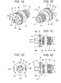
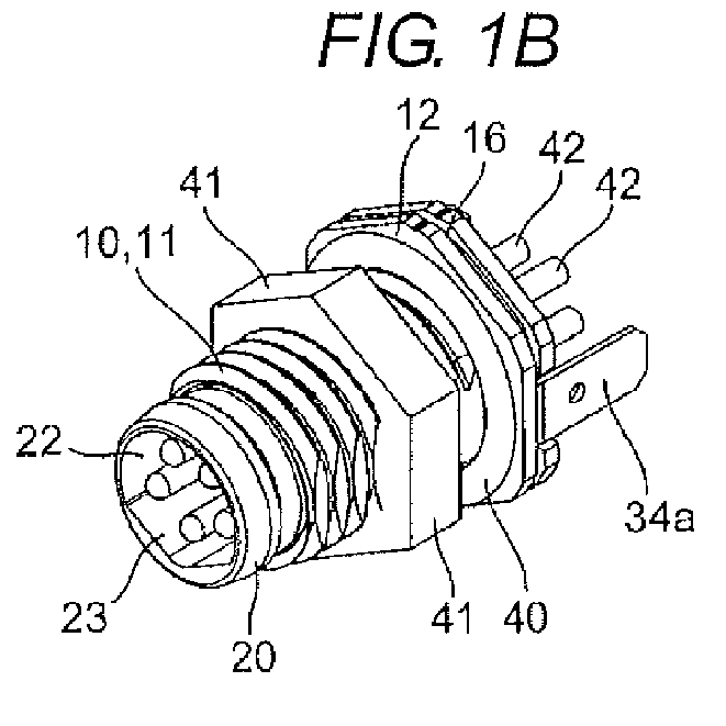
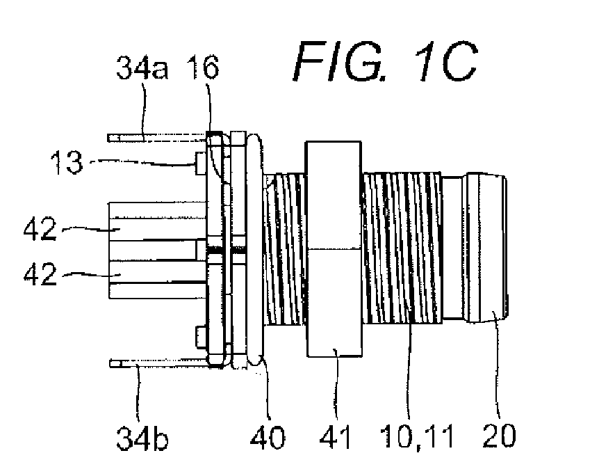
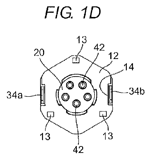
Fig. 1 illustrates a connector in which a ground terminal according to a first embodiment of the present invention is assembled, andFigs. 1A, 1B, 1C, 1D, and 1E are a perspective view, a different-angle perspective view, a plan view, a front view, and a right side view of the connector, respectively; -
Fig. 2 illustrates a state in which the connector inFig. 1 is attached to a printed board, andFigs. 2A, 2B, 2C, 2D, and 2E are a perspective view, a different-angle perspective view, a plan view, a front view, and a right side view of the connector attached to the printed board, respectively; -
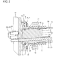
Fig. 3 is a longitudinal sectional perspective view illustrating the connector inFig. 2A ; -
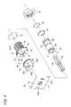
Fig. 4 is an exploded perspective view of the connector inFig. 2A ; -
Fig. 5 illustrates the ground terminal inFig. 4 , andFigs. 5A, 5B, 5C, 5D, and 5E are a perspective view, a different-angle perspective view, a plan view, a front view, and a right side view of the connector of the ground terminal, respectively; -
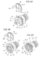
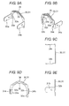
Fig. 6 illustrates a method for assembling the ground terminal in the connector inFig. 1 , andFigs. 6A, 6B, and 6C are a perspective view before the assembly, a partially sectional perspective view before the assembly, and a partially sectional perspective view after the assembly, respectively; -
Fig. 7 illustrates a ground terminal according to a second embodiment of the present invention, andFigs. 7A, 7B, 7C, 7D, and 7E are a perspective view, a different-angle perspective view, a plan view, a front view, and a right side view of the ground terminal, respectively; -
Fig. 8 illustrates a method for assembling the ground terminal inFig. 7 in the connector, andFigs. 8A, 8B, and 8C are a perspective view before the assembly, a partially sectional perspective view before the assembly, and a partially sectional perspective view after the assembly, respectively; -
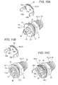
Fig. 9 illustrates a ground terminal according to a third embodiment of the present invention, andFigs. 9A, 9B, 9C, 9D, and 9E are a perspective view, a different-angle perspective view, a plan view, a front view, and a right side view of the ground terminal, respectively; -
Fig. 10 illustrates a method for assembling the ground terminal inFig. 9 in the connector, andFigs. 10A, 10B, and 10C are a perspective view before the assembly, a partially sectional perspective view before the assembly, and a partially sectional perspective view after the assembly, respectively; -
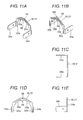
Fig. 11 illustrates a ground terminal according to a fourth embodiment of the present invention, andFigs. 11A, 11B, 11C, 11D, and 11E are a perspective view, a different-angle perspective view, a plan view, a front view, and a right side view of the ground terminal, respectively; -
Fig. 12 illustrates a method for assembling the ground terminal inFig. 11 in the connector, andFigs. 12A, 12B, and 12C are a perspective view before the assembly, a partially sectional perspective view before the assembly, and a partially sectional perspective view after the assembly, respectively; -
Fig. 13 illustrates a ground terminal assembled in a connector according to a fifth embodiment of the present invention, andFigs. 13A, 13B, 13C, 13D, and 13E are a perspective view, a different-angle perspective view, a plan view, a front view, and a right side view of the ground terminal, respectively; -
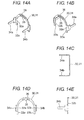
Fig. 14 illustrates the ground terminal of the fifth embodiment according to the present invention, andFigs. 14A, 14B, 14C, 14D, and 14E are a perspective view, a different-angle perspective view, a plan view, a front view, and a right side view of the ground terminal, respectively; and -
Fig. 15 illustrates a method for assembling the ground terminal inFig. 14 in the connector, andFigs. 15A, 15B, and 15C are a perspective view before the assembly, a partially sectional perspective view before the assembly, and a partially sectional perspective view after the assembly, respectively. - Hereinafter, ground terminals according to the present invention and connectors in which the ground terminals are assembled will be described with reference to the drawings of
Figs. 1 to 15 . - As illustrated in
Figs. 1 to 6 , a connector in which a ground terminal according to a first embodiment is assembled roughly includes aconnector body 10, asupport 20 assembled in theconnector body 10, aground terminal 30 attached to theconnector body 10, a sealing external O-ring 40 assembled in an outer circumferential surface of theconnector body 10, and anut 41 engaged with an external thread of the connector. - As illustrated in
Fig. 4 , theconnector body 10 is a metallic cylinder including anexternal thread 11 on the outer circumferential surface thereof, and aguard portion 12 is provided in one end portion of theconnector body 10. In theguard portion 12,standoffs 13 are projected at predetermined intervals in an outward surface edge portion. Thestandoffs 13 are members provided to separate theconnector body 10 from a printedboard 50 described later with a predetermined distance.Notches 14 with whichterminal portions ground terminal 30 engage are formed in both side edge portions in a front surface of theguard portion 12.Position regulating projections 15 that regulate a position of thesupport 20 are formed at predetermined intervals at an opening edge exposed from theguard portion 12. As illustrated inFig. 6 , in theguard portion 12, anengagement groove 16 having a substantial U-shape in section is formed along an outer circumferential end face, and a pair oflatch receiving portions pawls ground terminal 30 can be latched is formed in a bottom surface of theengagement groove 16. As illustrated inFig. 3 , a positioningannular groove portion 18 is formed along an inner circumferential surface of theconnector body 10. - The
support 20 is a substantially columnar resin molding product that can be inserted in theconnector body 10, plural pin terminal holes 21 in each of which apin terminal 42 can be inserted are made in parallel with an axial center, and a plug recess 22 (Figs. 2B and3 ) in which a plug (not illustrated) is fitted is formed on one end side of thesupport 20. A substantial V-shape position regulating step portion 23 (Fig. 2B ) is formed in theplug recess 22. Afirst engagement groove 24 is formed on one end side in the outer circumferential surface of thesupport 20 in order to engage with a positioning C-ring 43, and asecond engagement groove 25 is formed in a substantially central portion in the outer circumferential surface of thesupport 20 in order to elastically engage with a sealing internal O-ring 44. A position regulating receivingportion 26 is notched on the other end side of thesupport 20 - As illustrated in
Fig. 5 , a conductive elastic plate material is punched and pressed into theground terminal 30, and latchingpawls elastic arms central coupling portion 31. Theterminal portions elastic arms central coupling portion 31, aslit 36 is formed along a longitudinal-and-latitudinal direction, and an inner circumferential edge portion is bent to provide aprojection 35. - As illustrated in
Fig. 4 , in the printedboard 50 to which the connector having the above configuration is connected, signal terminal holes 51 are concentrically made at equal intervals, andground terminal holes - A method for assembling the connector will be described below.
- The
pin terminal 42 is inserted in thepin terminal hole 21 of thesupport 20 to project one end of thepin terminal 42 into the plug recess 22 (Fig. 3 ), and the positioning C-ring 43 and the sealing internal O-ring 44 are placed on the first andsecond engagement grooves support 20 is inserted in theconnector body 10, whereby the positioning C-ring 43 engages with the positioningannular groove portion 18, which is provided in the inner circumferential surface of theconnector body 10, and is placed at a predetermined position. The sealing internal O-ring 44 is pressed against the inner circumferential surface of theconnector body 10 to form a sealing structure. The position regulating receivingportion 26 of thesupport 20 engages with theposition regulating projection 15 provided in theconnector body 10, thereby preventing rotation of thesupport 20. - As illustrated in
Fig. 6 , theelastic arms ground terminal 30 are inserted and assembled in theengagement groove 16 provided in theguard portion 12 of theconnector body 10. Therefore, theprojection 35 is elastically deformed by abutting on the bottom surface of theengagement groove 16, and the latchingpawls elastic arms latch receiving portion connector body 10. Theterminal portions elastic arms notches 14 provided in theguard portion 12 to regulate the positions of theterminal portions Fig. 1 A) . At this point, in the first embodiment, a repulsive force of theprojection 35 applies a force in the direction separating from the bottom surface of theengagement groove 16, and the force acts in the direction in which a distance between the latchingpawls central coupling portion 31 and theelastic arms ground terminal 30 is prevented from disengagement in theconnector body 10 at three points, namely, the pair of latchingpawls projection 35, thereby obtaining a support structure having a resistance to a disturbance such as a vibration. - As illustrated in
Fig. 2 , the assembly work is completed by inserting thepin terminals 42 and theterminal portions ground terminal 30, which project from the connector, in the signal terminal holes 51 and theground terminal holes board 50 and soldering them. - Finally, one end portion of the connector is inserted in an attaching hole made in a housing of an electric instrument (not illustrated), and the
external thread 11 of the projectedconnector body 10 is screwed with thenut 41 to be able to fix the connector to the housing of the electric instrument. The other end portion of thepin terminal 42 is connected to a lead wire (not illustrated), and the plug (not illustrated) is fitted in theplug recess 22 of thesupport 20 to complete the connection work. - As illustrated in
Figs. 7 and8 , a second embodiment is substantially similar to those of the first embodiment, and differs from the first embodiment in that the projection and the slit are not provided but a continuous arc is formed by thecentral coupling portion 31 and the inner circumferential edge portions of theelastic arms - The
central coupling portion 31 is slightly curved by performing press working in a plate thickness direction. This is because dropout is prevented due to the vibration by press-fitting thecentral coupling portion 31 in theengagement groove 16 provided in theguard portion 12 of theconnector body 10. - According to the second embodiment, the connector, in which the
central coupling portion 31 has large mechanical strength while theground terminal 30 has the large retaining force, is advantageously obtained. - Because other configurations are substantially similar to those of the first embodiment, the identical component is designated by the identical numeral and the description is omitted.
- As illustrated in
Figs. 9 and10 , a third embodiment is substantially similar to those of the first embodiment, and differs from the first embodiment in that lengths of pair ofelastic arms - According to the third embodiment, because the latching
pawl 33a having the shorterelastic arm 32a can be latched after the latchingpawl 33b having the longerelastic arm 32b is latched, advantageously the work to assemble theground terminal 30 is further facilitated to obtain the connector with high-productivity. - Because other configurations are substantially similar to those of the first embodiment, the identical component is designated by the identical numeral and the description is omitted.
- As illustrated in
Figs. 11 and12 , a fourth embodiment is substantially similar to those of the first embodiment, and differs from the first embodiment in that the latching pawls are not provided in the leading end portions of theelastic arms pawls projection 35 in the inner circumferential edge of thecentral coupling portion 31. - According to the fourth embodiment, advantageously a connector with high-productivity is obtained because the distance necessary to assemble the
ground terminal 30 is shortened to facilitate the assemble work. - Because other configurations are substantially similar to those of the first embodiment, the identical component is designated by the identical numeral and the description is omitted.
- As illustrated in
Figs. 13 to 15 , a fifth embodiment is substantially similar to those of the first embodiment, and differs from the first embodiment in the following points. That is, the continuous arc is formed by thecentral coupling portion 31 and the inner circumferential edge portions of theelastic arms projection 35 projects in the inner circumferential edge of thecentral coupling portion 31,short slit 36 is formed, and theterminal portions - According to the fifth embodiment, advantageously the terminal portion can be selected from various shapes to enhance a design degree of freedom.
- In the above embodiments, the
ground terminal 30 is prevented from disengagement in theconnector body 10 with the latching pawl interposed therebetween. Alternatively, theground terminal 30 may be prevented from disengagement by press-fitting. - The present invention is not limited to the above ground terminal and connector, but the present invention may be applied to ground terminals and connectors having other shapes.
Claims (13)
- A ground terminal (30) comprising:a terminal portion configured to be electrically connected to an outside device; andelastic arms (32a, 32b) configured to extend in an identical direction from both ends of a central coupling portion,wherein a pair of latching pawls (33a, 33b) is provided in at least one of an inner circumferential edge of the central coupling portion (31) and inner circumferential edges of the elastic arms (32a, 32b).
- The ground terminal (30) according to claim 1, wherein the pair of latching pawls (33a, 33b) is provided respectively in leading end portions of the elastic arms (32a,32b).
- The ground terminal (30) according to claim 1 or 2, wherein a slit (36) is provided along a longitudinal-and-latitudinal direction of the central coupling portion (31).
- The ground terminal (30) according to any one of claims 1 to 3, wherein at least one projection is provided in the inner circumferential edge of the central coupling portion (31).
- The ground terminal (30) according to claim 4, wherein the slit (36) extends to both ends of the central coupling portion (31).
- The ground terminal (30) according to claim 4, wherein the projection is curved.
- The ground terminal (30) according to claim 1, wherein a continuous arc is formed by the inner circumferential edges of the central coupling portion (31) and the elastic arms (32a, 32b).
- The ground terminal (30) according to claim 1 or 7, wherein the elastic arms (32a, 32b) adjacent to each other differ from each other in length.
- The ground terminal (30) according to any one of claims 1, 7, and 8, wherein the pair of latching pawls (33a, 33b) is provided in the inner circumferential edge of the central coupling portion (31) wherein the pawls are opposed to each other.
- A connector, comprising:the ground terminal (30) according to any one of claims 1 to 9 .
- The connector according to claim 10, wherein the central coupling portion (31) and the elastic arms (32a, 32b) of the ground terminal (30) are inserted and prevented from disengagement in an engagement groove (16) having a substantial U-shape in section, the engagement groove (16) being formed along an outer circumferential end face of a guard portion (12) disposed on one end side of a connector body (10).
- The connector according to claim 10 or 11, wherein a latch receiving portion is provided in a bottom surface of the engagement groove (16), the latch receiving portion being able to be latched in the latching pawl of the ground terminal (30).
- The connector according to any one of claims 10 to 12, wherein a notch (14) is provided in the guard portion (12) of the connector body (10), the notch (14) being able to engage with a terminal portion of the ground terminal (30).
Applications Claiming Priority (1)
| Application Number | Priority Date | Filing Date | Title |
|---|---|---|---|
| JP2012256479A JP6044298B2 (en) | 2012-11-22 | 2012-11-22 | Ground terminal and connector using the same |
Publications (2)
| Publication Number | Publication Date |
|---|---|
| EP2736128A1 true EP2736128A1 (en) | 2014-05-28 |
| EP2736128B1 EP2736128B1 (en) | 2020-04-08 |
Family
ID=49626849
Family Applications (1)
| Application Number | Title | Priority Date | Filing Date |
|---|---|---|---|
| EP13194078.5A Active EP2736128B1 (en) | 2012-11-22 | 2013-11-22 | Ground terminal and connector provided therewith |
Country Status (4)
| Country | Link |
|---|---|
| US (1) | US9184544B2 (en) |
| EP (1) | EP2736128B1 (en) |
| JP (1) | JP6044298B2 (en) |
| CN (1) | CN103840319B (en) |
Cited By (2)
| Publication number | Priority date | Publication date | Assignee | Title |
|---|---|---|---|---|
| EP4231463A1 (en) * | 2022-02-21 | 2023-08-23 | PROVERTHA Connectors, Cables & Solutions GmbH | Connector for mounting on a printed circuit board |
| WO2024223376A1 (en) * | 2023-04-28 | 2024-10-31 | Phoenix Contact Gmbh & Co. Kg | Plug connector part with electrically connectable shields |
Families Citing this family (15)
| Publication number | Priority date | Publication date | Assignee | Title |
|---|---|---|---|---|
| US9635788B2 (en) * | 2010-12-08 | 2017-04-25 | Ezconn Corporation | Shielding device |
| USD730839S1 (en) | 2012-11-13 | 2015-06-02 | Omron Corporation | Electric connector |
| JP2014219436A (en) * | 2013-04-30 | 2014-11-20 | 株式会社リコー | Read-out device and image forming apparatus including the device |
| USD756929S1 (en) * | 2013-09-30 | 2016-05-24 | Danfoss A/S | Electrical connector for refrigeration valve |
| CN207265325U (en) * | 2017-07-13 | 2018-04-20 | 泰科电子(上海)有限公司 | Connector |
| DE102017123539B3 (en) * | 2017-10-10 | 2019-01-03 | HARTING Electronics GmbH | Printed circuit board connector with a screen element |
| DE102018103639B3 (en) * | 2018-02-19 | 2019-06-06 | Harting Electric Gmbh & Co. Kg | Printed circuit board connector with a shield connection element |
| USD859320S1 (en) * | 2018-02-24 | 2019-09-10 | Dsm&T Company, Inc. | Mating section of male electrical connector |
| USD915292S1 (en) | 2019-01-22 | 2021-04-06 | Dsm&T Company, Inc. | Electrical connector insert |
| USD929342S1 (en) | 2020-02-24 | 2021-08-31 | Dsm&T Company, Inc. | Connector with locking arms |
| USD924158S1 (en) | 2020-02-24 | 2021-07-06 | Dsm&T Company, Inc. | Connector with locking tabs |
| USD998570S1 (en) | 2021-01-19 | 2023-09-12 | Dsm&T Company, Inc. | Triangular electrical connector with flange |
| USD964287S1 (en) | 2021-01-19 | 2022-09-20 | Dsm&T Company, Inc. | Electrical connector with flange |
| USD1056852S1 (en) * | 2022-01-13 | 2025-01-07 | Georg Schlegel Gmbh & Co. Kg | Electrical switching element |
| EP4636960A1 (en) * | 2024-04-19 | 2025-10-22 | Rosenberger Hochfrequenztechnik GmbH & Co. KG | Circuit board connector, circuit board assembly and method for assembling a circuit board connector |
Citations (10)
| Publication number | Priority date | Publication date | Assignee | Title |
|---|---|---|---|---|
| US5145412A (en) * | 1991-10-18 | 1992-09-08 | Foxconn International, Inc. | Filter connector |
| US5326280A (en) * | 1993-06-14 | 1994-07-05 | Amphenol Corporation | Coaxial connector with integral decoupling unit |
| US5482477A (en) * | 1994-06-28 | 1996-01-09 | The Whitaker Corporation | Micro-miniature coaxial connector with positive locking member |
| US20030094299A1 (en) * | 2001-11-20 | 2003-05-22 | Lee Hsiao Lung | Anti-disturbing device for terminals |
| EP1501171A1 (en) * | 2003-07-22 | 2005-01-26 | Itt Manufacturing Enterprises, Inc. | Plug connector device for compact servomotors |
| US7014480B1 (en) * | 2005-02-15 | 2006-03-21 | Tyco Electronics Corporation | Grounding methods and apparatus for connector assemblies |
| US7247052B2 (en) | 2003-10-08 | 2007-07-24 | Phoenix Contact Gmbh & Co. Kg | Shield connection |
| US20070224883A1 (en) * | 2006-03-21 | 2007-09-27 | Joymax Electronics Co., Ltd. | Electrical connector |
| DE202010009598U1 (en) * | 2010-06-28 | 2010-09-09 | Rosenberger Hochfrequenztechnik Gmbh & Co. Kg | Connector with outer conductor shield |
| US20110021042A1 (en) * | 2009-07-21 | 2011-01-27 | Tyco Electronics Corporation | Electrical connector assembly having shield member |
Family Cites Families (13)
| Publication number | Priority date | Publication date | Assignee | Title |
|---|---|---|---|---|
| JPH0113344Y2 (en) * | 1984-10-03 | 1989-04-19 | ||
| US5346403A (en) * | 1993-07-22 | 1994-09-13 | Itt Corporation | Connector grounding arrangement |
| US6203362B1 (en) * | 1998-11-13 | 2001-03-20 | Sumitomo Wiring Systems, Ltd. | Connector |
| US6364693B1 (en) * | 1999-05-21 | 2002-04-02 | International Truck And Engine Corp. | Backshell with forced electrical connector orientation |
| US20020112078A1 (en) * | 1999-12-03 | 2002-08-15 | David Yach | Virtual machine web browser |
| US6338645B1 (en) * | 2000-07-28 | 2002-01-15 | Apple Computer, Inc. | Connector having a cable that is relatively moveable about an axis |
| JP2002289289A (en) * | 2001-03-28 | 2002-10-04 | Sumitomo Wiring Syst Ltd | Connectors and terminals |
| JP3717814B2 (en) * | 2001-07-31 | 2005-11-16 | 矢崎総業株式会社 | Two article locking structure |
| JP4190305B2 (en) * | 2003-02-20 | 2008-12-03 | 富士通コンポーネント株式会社 | Connector with cable |
| JP3948525B2 (en) * | 2003-04-28 | 2007-07-25 | 矢崎総業株式会社 | Terminal disengagement jig |
| US7168987B1 (en) * | 2005-07-12 | 2007-01-30 | Fujitsu Component Limited | Right angle type connector used for balanced transmission of data signals |
| US7413473B2 (en) * | 2005-08-26 | 2008-08-19 | Hon Hai Precision Ind. Co., Ltd. | Cable connector assembly with EMI gasket |
| JP5186186B2 (en) * | 2007-11-15 | 2013-04-17 | 矢崎総業株式会社 | Shield shell mounting structure |
-
2012
- 2012-11-22 JP JP2012256479A patent/JP6044298B2/en active Active
-
2013
- 2013-11-22 CN CN201310598139.6A patent/CN103840319B/en not_active Expired - Fee Related
- 2013-11-22 EP EP13194078.5A patent/EP2736128B1/en active Active
- 2013-11-22 US US14/087,178 patent/US9184544B2/en active Active
Patent Citations (10)
| Publication number | Priority date | Publication date | Assignee | Title |
|---|---|---|---|---|
| US5145412A (en) * | 1991-10-18 | 1992-09-08 | Foxconn International, Inc. | Filter connector |
| US5326280A (en) * | 1993-06-14 | 1994-07-05 | Amphenol Corporation | Coaxial connector with integral decoupling unit |
| US5482477A (en) * | 1994-06-28 | 1996-01-09 | The Whitaker Corporation | Micro-miniature coaxial connector with positive locking member |
| US20030094299A1 (en) * | 2001-11-20 | 2003-05-22 | Lee Hsiao Lung | Anti-disturbing device for terminals |
| EP1501171A1 (en) * | 2003-07-22 | 2005-01-26 | Itt Manufacturing Enterprises, Inc. | Plug connector device for compact servomotors |
| US7247052B2 (en) | 2003-10-08 | 2007-07-24 | Phoenix Contact Gmbh & Co. Kg | Shield connection |
| US7014480B1 (en) * | 2005-02-15 | 2006-03-21 | Tyco Electronics Corporation | Grounding methods and apparatus for connector assemblies |
| US20070224883A1 (en) * | 2006-03-21 | 2007-09-27 | Joymax Electronics Co., Ltd. | Electrical connector |
| US20110021042A1 (en) * | 2009-07-21 | 2011-01-27 | Tyco Electronics Corporation | Electrical connector assembly having shield member |
| DE202010009598U1 (en) * | 2010-06-28 | 2010-09-09 | Rosenberger Hochfrequenztechnik Gmbh & Co. Kg | Connector with outer conductor shield |
Cited By (3)
| Publication number | Priority date | Publication date | Assignee | Title |
|---|---|---|---|---|
| EP4231463A1 (en) * | 2022-02-21 | 2023-08-23 | PROVERTHA Connectors, Cables & Solutions GmbH | Connector for mounting on a printed circuit board |
| WO2024223376A1 (en) * | 2023-04-28 | 2024-10-31 | Phoenix Contact Gmbh & Co. Kg | Plug connector part with electrically connectable shields |
| BE1031560B1 (en) * | 2023-04-28 | 2024-11-29 | Phoenix Contact Gmbh & Co | connector part with electrically connectable shields |
Also Published As
| Publication number | Publication date |
|---|---|
| US9184544B2 (en) | 2015-11-10 |
| US20140141634A1 (en) | 2014-05-22 |
| JP6044298B2 (en) | 2016-12-14 |
| JP2014107011A (en) | 2014-06-09 |
| CN103840319A (en) | 2014-06-04 |
| EP2736128B1 (en) | 2020-04-08 |
| CN103840319B (en) | 2017-11-03 |
Similar Documents
| Publication | Publication Date | Title |
|---|---|---|
| EP2736128B1 (en) | Ground terminal and connector provided therewith | |
| US10199770B2 (en) | Connector | |
| US10096918B1 (en) | Connector | |
| US9172194B2 (en) | Coaxial connector plug | |
| CN101183758B (en) | Electrical connector | |
| CN102474058B (en) | Coaxial connector and method for assembling same | |
| JP6006356B2 (en) | Contact and connector using the contact | |
| JP2014107011A5 (en) | ||
| CN211238575U (en) | Substrate mounting type coaxial connector | |
| JP2012164520A (en) | Relay connector | |
| JP4874208B2 (en) | Plug-in connector | |
| JP4916031B2 (en) | Fixing tool and electrical connector using the fixing tool | |
| EP2937950A2 (en) | Connector | |
| JP2016197584A (en) | Electric connector | |
| US10770819B2 (en) | Connector | |
| CN101145462A (en) | switchgear | |
| JP6681655B2 (en) | Coaxial connector | |
| US12095184B2 (en) | Connector and connector assembly | |
| JP2019114623A (en) | Cable connection structure used for vehicle antenna device | |
| KR101976695B1 (en) | Electric terminal assembly structure press fitted in printed circuit board | |
| JP2021114397A (en) | connector | |
| JP5922325B2 (en) | Circuit board electrical connector | |
| JP5567868B2 (en) | Receptacle coaxial connector | |
| EP4343974A1 (en) | Connector | |
| JP6692130B2 (en) | Electrical equipment and communication cables |
Legal Events
| Date | Code | Title | Description |
|---|---|---|---|
| PUAI | Public reference made under article 153(3) epc to a published international application that has entered the european phase |
Free format text: ORIGINAL CODE: 0009012 |
|
| 17P | Request for examination filed |
Effective date: 20131122 |
|
| AK | Designated contracting states |
Kind code of ref document: A1 Designated state(s): AL AT BE BG CH CY CZ DE DK EE ES FI FR GB GR HR HU IE IS IT LI LT LU LV MC MK MT NL NO PL PT RO RS SE SI SK SM TR |
|
| AX | Request for extension of the european patent |
Extension state: BA ME |
|
| R17P | Request for examination filed (corrected) |
Effective date: 20141127 |
|
| RBV | Designated contracting states (corrected) |
Designated state(s): AL AT BE BG CH CY CZ DE DK EE ES FI FR GB GR HR HU IE IS IT LI LT LU LV MC MK MT NL NO PL PT RO RS SE SI SK SM TR |
|
| 17Q | First examination report despatched |
Effective date: 20160719 |
|
| STAA | Information on the status of an ep patent application or granted ep patent |
Free format text: STATUS: EXAMINATION IS IN PROGRESS |
|
| GRAP | Despatch of communication of intention to grant a patent |
Free format text: ORIGINAL CODE: EPIDOSNIGR1 |
|
| STAA | Information on the status of an ep patent application or granted ep patent |
Free format text: STATUS: GRANT OF PATENT IS INTENDED |
|
| RIC1 | Information provided on ipc code assigned before grant |
Ipc: H01R 13/426 20060101ALN20191111BHEP Ipc: H01R 13/6595 20110101AFI20191111BHEP Ipc: H01R 24/86 20110101ALN20191111BHEP Ipc: H01R 12/70 20110101ALN20191111BHEP |
|
| INTG | Intention to grant announced |
Effective date: 20191127 |
|
| GRAS | Grant fee paid |
Free format text: ORIGINAL CODE: EPIDOSNIGR3 |
|
| GRAA | (expected) grant |
Free format text: ORIGINAL CODE: 0009210 |
|
| STAA | Information on the status of an ep patent application or granted ep patent |
Free format text: STATUS: THE PATENT HAS BEEN GRANTED |
|
| AK | Designated contracting states |
Kind code of ref document: B1 Designated state(s): AL AT BE BG CH CY CZ DE DK EE ES FI FR GB GR HR HU IE IS IT LI LT LU LV MC MK MT NL NO PL PT RO RS SE SI SK SM TR |
|
| REG | Reference to a national code |
Ref country code: AT Ref legal event code: REF Ref document number: 1255618 Country of ref document: AT Kind code of ref document: T Effective date: 20200415 Ref country code: CH Ref legal event code: EP |
|
| REG | Reference to a national code |
Ref country code: DE Ref legal event code: R096 Ref document number: 602013067631 Country of ref document: DE |
|
| REG | Reference to a national code |
Ref country code: IE Ref legal event code: FG4D |
|
| REG | Reference to a national code |
Ref country code: NL Ref legal event code: MP Effective date: 20200408 |
|
| REG | Reference to a national code |
Ref country code: LT Ref legal event code: MG4D |
|
| PG25 | Lapsed in a contracting state [announced via postgrant information from national office to epo] |
Ref country code: NO Free format text: LAPSE BECAUSE OF FAILURE TO SUBMIT A TRANSLATION OF THE DESCRIPTION OR TO PAY THE FEE WITHIN THE PRESCRIBED TIME-LIMIT Effective date: 20200708 Ref country code: GR Free format text: LAPSE BECAUSE OF FAILURE TO SUBMIT A TRANSLATION OF THE DESCRIPTION OR TO PAY THE FEE WITHIN THE PRESCRIBED TIME-LIMIT Effective date: 20200709 Ref country code: LT Free format text: LAPSE BECAUSE OF FAILURE TO SUBMIT A TRANSLATION OF THE DESCRIPTION OR TO PAY THE FEE WITHIN THE PRESCRIBED TIME-LIMIT Effective date: 20200408 Ref country code: NL Free format text: LAPSE BECAUSE OF FAILURE TO SUBMIT A TRANSLATION OF THE DESCRIPTION OR TO PAY THE FEE WITHIN THE PRESCRIBED TIME-LIMIT Effective date: 20200408 Ref country code: SE Free format text: LAPSE BECAUSE OF FAILURE TO SUBMIT A TRANSLATION OF THE DESCRIPTION OR TO PAY THE FEE WITHIN THE PRESCRIBED TIME-LIMIT Effective date: 20200408 Ref country code: PT Free format text: LAPSE BECAUSE OF FAILURE TO SUBMIT A TRANSLATION OF THE DESCRIPTION OR TO PAY THE FEE WITHIN THE PRESCRIBED TIME-LIMIT Effective date: 20200817 Ref country code: FI Free format text: LAPSE BECAUSE OF FAILURE TO SUBMIT A TRANSLATION OF THE DESCRIPTION OR TO PAY THE FEE WITHIN THE PRESCRIBED TIME-LIMIT Effective date: 20200408 Ref country code: IS Free format text: LAPSE BECAUSE OF FAILURE TO SUBMIT A TRANSLATION OF THE DESCRIPTION OR TO PAY THE FEE WITHIN THE PRESCRIBED TIME-LIMIT Effective date: 20200808 |
|
| REG | Reference to a national code |
Ref country code: AT Ref legal event code: MK05 Ref document number: 1255618 Country of ref document: AT Kind code of ref document: T Effective date: 20200408 |
|
| PG25 | Lapsed in a contracting state [announced via postgrant information from national office to epo] |
Ref country code: LV Free format text: LAPSE BECAUSE OF FAILURE TO SUBMIT A TRANSLATION OF THE DESCRIPTION OR TO PAY THE FEE WITHIN THE PRESCRIBED TIME-LIMIT Effective date: 20200408 Ref country code: HR Free format text: LAPSE BECAUSE OF FAILURE TO SUBMIT A TRANSLATION OF THE DESCRIPTION OR TO PAY THE FEE WITHIN THE PRESCRIBED TIME-LIMIT Effective date: 20200408 Ref country code: RS Free format text: LAPSE BECAUSE OF FAILURE TO SUBMIT A TRANSLATION OF THE DESCRIPTION OR TO PAY THE FEE WITHIN THE PRESCRIBED TIME-LIMIT Effective date: 20200408 Ref country code: BG Free format text: LAPSE BECAUSE OF FAILURE TO SUBMIT A TRANSLATION OF THE DESCRIPTION OR TO PAY THE FEE WITHIN THE PRESCRIBED TIME-LIMIT Effective date: 20200708 |
|
| PG25 | Lapsed in a contracting state [announced via postgrant information from national office to epo] |
Ref country code: AL Free format text: LAPSE BECAUSE OF FAILURE TO SUBMIT A TRANSLATION OF THE DESCRIPTION OR TO PAY THE FEE WITHIN THE PRESCRIBED TIME-LIMIT Effective date: 20200408 |
|
| REG | Reference to a national code |
Ref country code: DE Ref legal event code: R097 Ref document number: 602013067631 Country of ref document: DE |
|
| PG25 | Lapsed in a contracting state [announced via postgrant information from national office to epo] |
Ref country code: IT Free format text: LAPSE BECAUSE OF FAILURE TO SUBMIT A TRANSLATION OF THE DESCRIPTION OR TO PAY THE FEE WITHIN THE PRESCRIBED TIME-LIMIT Effective date: 20200408 Ref country code: RO Free format text: LAPSE BECAUSE OF FAILURE TO SUBMIT A TRANSLATION OF THE DESCRIPTION OR TO PAY THE FEE WITHIN THE PRESCRIBED TIME-LIMIT Effective date: 20200408 Ref country code: CZ Free format text: LAPSE BECAUSE OF FAILURE TO SUBMIT A TRANSLATION OF THE DESCRIPTION OR TO PAY THE FEE WITHIN THE PRESCRIBED TIME-LIMIT Effective date: 20200408 Ref country code: ES Free format text: LAPSE BECAUSE OF FAILURE TO SUBMIT A TRANSLATION OF THE DESCRIPTION OR TO PAY THE FEE WITHIN THE PRESCRIBED TIME-LIMIT Effective date: 20200408 Ref country code: SM Free format text: LAPSE BECAUSE OF FAILURE TO SUBMIT A TRANSLATION OF THE DESCRIPTION OR TO PAY THE FEE WITHIN THE PRESCRIBED TIME-LIMIT Effective date: 20200408 Ref country code: EE Free format text: LAPSE BECAUSE OF FAILURE TO SUBMIT A TRANSLATION OF THE DESCRIPTION OR TO PAY THE FEE WITHIN THE PRESCRIBED TIME-LIMIT Effective date: 20200408 Ref country code: AT Free format text: LAPSE BECAUSE OF FAILURE TO SUBMIT A TRANSLATION OF THE DESCRIPTION OR TO PAY THE FEE WITHIN THE PRESCRIBED TIME-LIMIT Effective date: 20200408 Ref country code: DK Free format text: LAPSE BECAUSE OF FAILURE TO SUBMIT A TRANSLATION OF THE DESCRIPTION OR TO PAY THE FEE WITHIN THE PRESCRIBED TIME-LIMIT Effective date: 20200408 |
|
| PLBE | No opposition filed within time limit |
Free format text: ORIGINAL CODE: 0009261 |
|
| STAA | Information on the status of an ep patent application or granted ep patent |
Free format text: STATUS: NO OPPOSITION FILED WITHIN TIME LIMIT |
|
| PG25 | Lapsed in a contracting state [announced via postgrant information from national office to epo] |
Ref country code: PL Free format text: LAPSE BECAUSE OF FAILURE TO SUBMIT A TRANSLATION OF THE DESCRIPTION OR TO PAY THE FEE WITHIN THE PRESCRIBED TIME-LIMIT Effective date: 20200408 Ref country code: SK Free format text: LAPSE BECAUSE OF FAILURE TO SUBMIT A TRANSLATION OF THE DESCRIPTION OR TO PAY THE FEE WITHIN THE PRESCRIBED TIME-LIMIT Effective date: 20200408 |
|
| 26N | No opposition filed |
Effective date: 20210112 |
|
| PG25 | Lapsed in a contracting state [announced via postgrant information from national office to epo] |
Ref country code: SI Free format text: LAPSE BECAUSE OF FAILURE TO SUBMIT A TRANSLATION OF THE DESCRIPTION OR TO PAY THE FEE WITHIN THE PRESCRIBED TIME-LIMIT Effective date: 20200408 |
|
| PG25 | Lapsed in a contracting state [announced via postgrant information from national office to epo] |
Ref country code: MC Free format text: LAPSE BECAUSE OF FAILURE TO SUBMIT A TRANSLATION OF THE DESCRIPTION OR TO PAY THE FEE WITHIN THE PRESCRIBED TIME-LIMIT Effective date: 20200408 |
|
| REG | Reference to a national code |
Ref country code: CH Ref legal event code: PL |
|
| GBPC | Gb: european patent ceased through non-payment of renewal fee |
Effective date: 20201122 |
|
| PG25 | Lapsed in a contracting state [announced via postgrant information from national office to epo] |
Ref country code: LU Free format text: LAPSE BECAUSE OF NON-PAYMENT OF DUE FEES Effective date: 20201122 |
|
| REG | Reference to a national code |
Ref country code: BE Ref legal event code: MM Effective date: 20201130 |
|
| PG25 | Lapsed in a contracting state [announced via postgrant information from national office to epo] |
Ref country code: LI Free format text: LAPSE BECAUSE OF NON-PAYMENT OF DUE FEES Effective date: 20201130 Ref country code: CH Free format text: LAPSE BECAUSE OF NON-PAYMENT OF DUE FEES Effective date: 20201130 |
|
| PG25 | Lapsed in a contracting state [announced via postgrant information from national office to epo] |
Ref country code: IE Free format text: LAPSE BECAUSE OF NON-PAYMENT OF DUE FEES Effective date: 20201122 Ref country code: FR Free format text: LAPSE BECAUSE OF NON-PAYMENT OF DUE FEES Effective date: 20201130 |
|
| PG25 | Lapsed in a contracting state [announced via postgrant information from national office to epo] |
Ref country code: GB Free format text: LAPSE BECAUSE OF NON-PAYMENT OF DUE FEES Effective date: 20201122 |
|
| PG25 | Lapsed in a contracting state [announced via postgrant information from national office to epo] |
Ref country code: TR Free format text: LAPSE BECAUSE OF FAILURE TO SUBMIT A TRANSLATION OF THE DESCRIPTION OR TO PAY THE FEE WITHIN THE PRESCRIBED TIME-LIMIT Effective date: 20200408 Ref country code: MT Free format text: LAPSE BECAUSE OF FAILURE TO SUBMIT A TRANSLATION OF THE DESCRIPTION OR TO PAY THE FEE WITHIN THE PRESCRIBED TIME-LIMIT Effective date: 20200408 Ref country code: CY Free format text: LAPSE BECAUSE OF FAILURE TO SUBMIT A TRANSLATION OF THE DESCRIPTION OR TO PAY THE FEE WITHIN THE PRESCRIBED TIME-LIMIT Effective date: 20200408 |
|
| PG25 | Lapsed in a contracting state [announced via postgrant information from national office to epo] |
Ref country code: MK Free format text: LAPSE BECAUSE OF FAILURE TO SUBMIT A TRANSLATION OF THE DESCRIPTION OR TO PAY THE FEE WITHIN THE PRESCRIBED TIME-LIMIT Effective date: 20200408 |
|
| PG25 | Lapsed in a contracting state [announced via postgrant information from national office to epo] |
Ref country code: BE Free format text: LAPSE BECAUSE OF NON-PAYMENT OF DUE FEES Effective date: 20201130 |
|
| PGFP | Annual fee paid to national office [announced via postgrant information from national office to epo] |
Ref country code: DE Payment date: 20220621 Year of fee payment: 10 |
|
| REG | Reference to a national code |
Ref country code: DE Ref legal event code: R119 Ref document number: 602013067631 Country of ref document: DE |
|
| PG25 | Lapsed in a contracting state [announced via postgrant information from national office to epo] |
Ref country code: DE Free format text: LAPSE BECAUSE OF NON-PAYMENT OF DUE FEES Effective date: 20240601 |
|
| PG25 | Lapsed in a contracting state [announced via postgrant information from national office to epo] |
Ref country code: DE Free format text: LAPSE BECAUSE OF NON-PAYMENT OF DUE FEES Effective date: 20240601 |
|
| PG25 | Lapsed in a contracting state [announced via postgrant information from national office to epo] |
Ref country code: IS Free format text: LAPSE BECAUSE OF NON-PAYMENT OF DUE FEES Effective date: 20200808 |