JP3717814B2 - Two article locking structure - Google Patents
Two article locking structure Download PDFInfo
- Publication number
- JP3717814B2 JP3717814B2 JP2001232009A JP2001232009A JP3717814B2 JP 3717814 B2 JP3717814 B2 JP 3717814B2 JP 2001232009 A JP2001232009 A JP 2001232009A JP 2001232009 A JP2001232009 A JP 2001232009A JP 3717814 B2 JP3717814 B2 JP 3717814B2
- Authority
- JP
- Japan
- Prior art keywords
- locking
- arm
- main
- temporary
- article
- Prior art date
- Legal status (The legal status is an assumption and is not a legal conclusion. Google has not performed a legal analysis and makes no representation as to the accuracy of the status listed.)
- Expired - Fee Related
Links
Images


Classifications
-
- H—ELECTRICITY
- H01—ELECTRIC ELEMENTS
- H01R—ELECTRICALLY-CONDUCTIVE CONNECTIONS; STRUCTURAL ASSOCIATIONS OF A PLURALITY OF MUTUALLY-INSULATED ELECTRICAL CONNECTING ELEMENTS; COUPLING DEVICES; CURRENT COLLECTORS
- H01R13/00—Details of coupling devices of the kinds covered by groups H01R12/70 or H01R24/00 - H01R33/00
- H01R13/64—Means for preventing incorrect coupling
-
- H—ELECTRICITY
- H01—ELECTRIC ELEMENTS
- H01R—ELECTRICALLY-CONDUCTIVE CONNECTIONS; STRUCTURAL ASSOCIATIONS OF A PLURALITY OF MUTUALLY-INSULATED ELECTRICAL CONNECTING ELEMENTS; COUPLING DEVICES; CURRENT COLLECTORS
- H01R13/00—Details of coupling devices of the kinds covered by groups H01R12/70 or H01R24/00 - H01R33/00
- H01R13/62—Means for facilitating engagement or disengagement of coupling parts or for holding them in engagement
- H01R13/627—Snap or like fastening
- H01R13/6271—Latching means integral with the housing
- H01R13/6273—Latching means integral with the housing comprising two latching arms
-
- H—ELECTRICITY
- H01—ELECTRIC ELEMENTS
- H01R—ELECTRICALLY-CONDUCTIVE CONNECTIONS; STRUCTURAL ASSOCIATIONS OF A PLURALITY OF MUTUALLY-INSULATED ELECTRICAL CONNECTING ELEMENTS; COUPLING DEVICES; CURRENT COLLECTORS
- H01R13/00—Details of coupling devices of the kinds covered by groups H01R12/70 or H01R24/00 - H01R33/00
- H01R13/62—Means for facilitating engagement or disengagement of coupling parts or for holding them in engagement
- H01R13/639—Additional means for holding or locking coupling parts together, after engagement, e.g. separate keylock, retainer strap
-
- H—ELECTRICITY
- H01—ELECTRIC ELEMENTS
- H01R—ELECTRICALLY-CONDUCTIVE CONNECTIONS; STRUCTURAL ASSOCIATIONS OF A PLURALITY OF MUTUALLY-INSULATED ELECTRICAL CONNECTING ELEMENTS; COUPLING DEVICES; CURRENT COLLECTORS
- H01R13/00—Details of coupling devices of the kinds covered by groups H01R12/70 or H01R24/00 - H01R33/00
- H01R13/40—Securing contact members in or to a base or case; Insulating of contact members
- H01R13/42—Securing in a demountable manner
- H01R13/436—Securing a plurality of contact members by one locking piece or operation
- H01R13/4364—Insertion of locking piece from the front
- H01R13/4365—Insertion of locking piece from the front comprising a temporary and a final locking position
Description
【0001】
【発明の属する技術分野】
本発明は、例えばコネクタハウジングとフロントホルダとを仮係止及び本係止させるための二物品の係止構造に関するものである。
【0002】
【従来の技術】
図8は従来のホルダ付きコネクタの一形態を示すものである。
このホルダ付きコネクタ51は、合成樹脂製のコネクタハウジング52と、コネクタハウジング52内に前方から挿入されて端子収容室54を画成する合成樹脂製のフロントホルダ53とを備えたものである。
【0003】
コネクタハウジング52は内側にホルダ挿入室55と、挿入室55に続く端子収容室の後半部分56と、ホルダ挿入室55内に突出した端子係止ランス57とを備え、外側に相手側の雌型のコネクタ(図示せず)に対するロックアーム58を有している。
【0004】
フロントホルダ53は端壁と上下の壁部と中間の隔壁とを有し、端壁に相手コネクタの雄端子(図示せず)に対する挿入孔59が設けられている。なお、本明細書ではコネクタ嵌合室を有する側を雌型のコネクタ、コネクタ嵌合室に挿入される側を雄型のコネクタと定義する。
【0005】
フロントホルダ53はコネクタハウジング52内に前方から挿入されて図示しない係止手段でホルダ挿入室55内に固定される。次いで電線付きの端子60が後方から端子収容室54内に挿入され、係止ランス57で係止される。
【0006】
コネクタハウジング52とフロントホルダ53を別体に形成することで、コネクタ内部の係止ランス57等の複雑な形状を容易に且つ大型に成形できるという利点がある。
【0007】
コネクタハウジング52とフロントホルダ53との係止手段としては種々の形態のものが提案されている。図9〜図10はホルダ付きコネクタの係止構造の一形態を示すものである。
【0008】
図9において、符号61はコネクタハウジング、62はフロントホルダを示している。コネクタハウジング61には空部63が設けられ、空部63の一方の内壁に仮係止突起64、他方の内壁に本係止突起65が入口側から順に設けられている。フロントホルダ62には、空部63に進入するアーム66が突出して設けられ、アーム66の一側部に仮係止突起67、他側部に本係止突起68が順に設けられている。アーム66の中央にはスリット状の孔(中空部)69が設けられて、各係止突起67,68が内側に撓み可能となっている。
【0009】
図9の如く、フロントホルダ62の仮係止突起67がコネクタハウジング61の仮係止突起64を乗り越えた状態で、本係止突起65,68同士が相互に当接して、フロントホルダ62がコネクタハウジング61に仮係止(仮固定)される。この仮係止状態で、例えばコネクタハウジング61とフロントホルダ62とが次工程に搬送される。
【0010】
そして次工程で図10の如く、フロントホルダ62が完全に押し込まれる。フロントホルダ62の本係止突起68はコネクタハウジング61の本係止突起65を乗り越えて、フロントホルダ62の本係止突起68の後端がコネクタハウジング61の本係止突起65の後端に当接し、且つフロントホルダ62の基部側の端面70がコネクタハウジング61の前端面71に当接して、フロントホルダ62がコネクタハウジング61に本係止(本固定)される。なお、本明細書ではコネクタハウジング61への端子挿入方向とフロントホルダの挿入方向とをそれぞれ前と定義する。
【0011】
【発明が解決しようとする課題】
しかしながら、上記従来のホルダ付きコネクタの係止構造にあっては、フロントホルダ62を仮係止させるに要する押し込み力と、フロントホルダ62を本係止させるに要する押し込み力とがほぼ同じであるために、例えば自動組付機等において、フロントホルダ62をコネクタハウジング61に仮係止させた状態で搬送する等した場合に、フロントホルダ62が外部と干渉する等して不意に押し込まれてしまうという問題があった。その場合には、作業者が治具棒等を使って本係止を解除しなければならず、多くの手間を要していた。
【0012】
また、フロントホルダ62の仮係止は容易に行うことができ、本係止は強い力で確実に行えることが理想であるが、従来においては、フロントホルダ62の本係止力が弱く、フロントホルダ62が車両走行中の振動等で不意に外れやすいという問題があった。
【0013】
また、フロントホルダ62のアーム66の幅方向中央に撓み用のスリット状の孔(中空部)69を設けなければならないために、フロントホルダ62の樹脂成形時にアーム66の型抜き性が悪く、成形型が複雑化してコストが高くつくという問題があった。
【0014】
なお、上記したフロントホルダ62の係止以外でも、例えばコネクタや電気接続箱等に端子二重係止用のスペーサ等を挿入する際にも、仮係止手段と本係止手段が必要であり、これらの場合にも上記した問題は起こり得るものである。
【0015】
本発明は、上記した点に鑑み、フロントホルダとコネクタハウジングというような二つの物品を相互に仮係止させた際に、不意に本係止させてしまうことがなく、且つ本係止を強い力で確実に行うことができ、しかも、樹脂成形を容易に且つ安価に行わせることのできる二物品の係止構造を提供することを目的とする。
【0016】
【課題を解決するための手段】
上記目的を達成するために、本発明の請求項1に係る二物品の係止構造は、一方の物品に仮係止アームと本係止アームとを並列に設け、他方の物品に、仮係合部と本係合部とを有して該仮係止アームと該本係止アームとの間に進入するアーム受け部と、該アーム受け部の両側で一対のアームガイド部とを設けて成り、該本係止アームの長手方向中間部の本係止部が該本係合部を乗り越える際に該本係止アームの先端を摺接支持させる傾斜部を一方の該アームガイド部に設け、該仮係止アームの先端側の仮係止部が該仮係合部を乗り越えて、該本係止部が該本係合部に初期当接した際に、該本係止アームの先端と該傾斜部との間に隙間があり、該本係止アームが撓んで該本係止部が該本係合部を乗り越える際に、該本係止アームの先端が該傾斜部で支持されることを特徴とする。
【0017】
上記構成により、先ず仮係止アームがアーム受け部の仮係合部と係合して、両物品が仮係止され、次いで一方及び/又は他方の物品をさらに組付方向に押し込むことで、本係止アームがアーム受け部の本係合部に乗り上げつつ外側に撓み、本係止アームの先端外側部がアームガイド部の傾斜部に接して、本係止アームが傾斜した状態に両持ち支持される。これにより、本係止アームを撓ませるに要する力が増大し、仮係止よりも本係止させるのに大きな力が必要となる。これにより、仮係止から本係止への不意な移行が防止される。本係止アームが本係合部に乗り越えて係合することで両物品が本係止される。本係止を解除する際には、前記同様に本係止アームの先端外側部がアームガイド部の傾斜部に接して、本係止アームが両持ち支持されるから、仮係止の解除よりも大きな力を必要とする。これにより、不意な本係止の解除が防止される。また、両側のアームガイド部と中央のアーム受け部とに沿って一対の係止アームが案内されつつ進退するから、一対の係止アームの位置が正確に規定され、正確な仮係止力と本係止力とが得られる。
【0018】
請求項2に係る二物品の係止構造は、請求項1記載に係る二物品の係止構造において、前記アーム受け部が先端側に前記仮係合部を有し、該仮係合部よりも後方に前記本係合部を有することを特徴とする。
【0019】
上記構成により、仮係止アームの仮係止部がアーム受け部の仮係合部に乗り越えて係合すると同時に、本係止アームの本係止部がアーム受け部の本係合部に当接して、ガタ付きなく確実に仮係止状態が得られる。
【0020】
請求項3に係る二物品の係止構造は、請求項2に係る二物品の係止構造において、前記仮係止アームの先端側と他方の前記アームガイド部の先端側とに逃がし用の傾斜部を設けたことを特徴とする。
【0021】
上記構成により、仮係止アームの仮係止部がアーム受け部の仮係合部に乗り上げて、仮係止アームが外側に撓んだ際に、仮係止アームの先端外側の傾斜部が他方のアームガイド部の先端内側の傾斜部に沿ってスムーズに通過し、仮係止が小さな力で容易に行われる。
【0022】
請求項4に係る二物品の係止構造は、請求項1〜3の何れか1項に係る二物品の係止構造において、前記仮係止部と本係止部と仮係合部と本係合部とがそれぞれ突起であることを特徴とする。
【0023】
上記構成により、仮係止に際して仮係止部と仮係合部との係合と、本係止部と本係合部との当接とが確実に行われる。また、本係止に際して仮係止部がアーム受け部に沿って真直にスムーズに移動し、本係止部が本係合部に確実に係合する。
【0024】
請求項5に係る二物品の係止構造は、請求項1〜4の何れか1項に係る二物品の係止構造において、前記一方の物品がコネクタハウジングであり、前記他方の物品が、該コネクタハウジング内に端子収容室を画成させるフロントホルダであることを特徴とする。
【0025】
上記構成により、コネクタハウジングへのフロントホルダの仮係止から本係止への移行を仮係止よりも大きな力で行うようになり、フロントホルダの不意な押し込み(本係止)が防止され、且つ本係止の不意な解除が防止される。
【0026】
【発明の実施の形態】
以下に本発明の実施の形態を図面を用いて詳細に説明する。
図1〜図4は、本発明に係る二物品の係止構造の一実施形態を示すものである。
【0027】
この構造は、図1の如く、一方の物品1に設けられた左右一対の可撓性の仮係止アーム3と本係止アーム4と、他方の物品2に設けられ、一対の仮係止アーム3と本係止アーム4との間に進入する一本のアーム受け部5と、アーム受け部5の一側方に位置する真直な第一のアームガイド部6と、受け部5の他側方に位置する傾斜状の第二のアームガイド部7とで構成されている。
【0028】
仮係止アーム3と本係止アーム4とは片持ち梁状に同じ長さで真直に且つ平行に突出形成されている。一方の仮係止アーム3の先端内側に仮係止突起(仮係止部)8が一体に設けられ、先端外側に逃がし用の傾斜面(傾斜部)9が設けられている。仮係止突起8は略三角形状に形成され、アーム先端から内向きに鋭角的(比較的緩い勾配)に傾斜した傾斜面8aと、傾斜面8aの頂点から真直なアーム本体の内側面に短く鈍角的に交差した係止面8bとを有している。傾斜面8aはアーム受け部5に対する当接兼摺接面として作用する。
【0029】
他方の本係止アーム4には、長手方向中間部において梁状のアーム本体11の内側面に本係止突起(本係止部)12が一体に設けられている。本係止突起12は前記仮係止突起8よりもアーム長手方向後方に若干の距離をおいて配置され、略台形状に形成されて、前後の傾斜面12a,12bと中間の真直面12cとを有している。前後の傾斜面12a,12bは前記仮係止突起8の係止面8bと同程度の角度で梁状のアーム本体11の内側面に交差している。前側の傾斜面12aはアーム受け部5に対する当接兼摺接面として作用し、後側の傾斜面12bは係止面として作用する。
【0030】
仮係止突起8と本係止突起12との間にはアーム幅方向の隙間13が構成されている。仮係止突起8と本係止突起12との内向きの突出長さは同程度である。
【0031】
他方の物品2側のアーム受け部5は、一本の真直なレール状ないしは支柱状の受け部本体14と、受け部本体14の先端側に一体に設けられた仮係合突起(仮係合部)15と本係合突起(本係合部)16とで構成されている。仮係合突起15は前記仮係止アーム3の仮係止突起8に対応(対向)して受け部本体14の一側面において受け部先端側に配置され、本係合突起16は前記本係止アーム4の本係止突起12に対応(対向)して受け部本体14の他側面において仮係合突起15よりも少し受け部基端寄り(後方)に配置されている。
【0032】
仮係合突起15は、先端側の傾斜面15aと、傾斜面15aに続く真直面15cと、真直面15cから受け部本体14の一側面に直交する後方の係止面15bとを有している。傾斜面15aは仮係止アーム3の仮係止突起8の傾斜面8aよりも急勾配に形成され、アーム先端に比較的強く当接可能である。本明細書では各物品1,2の嵌合方向先端側をそれぞれ前側と定義している。
【0033】
本係合突起16は、受け部先端側の短い第一の傾斜面16aと、第一の傾斜面16aから後方に傾斜して延びる長い第二の傾斜面16cと、第二の傾斜面16cから受け部本体14の他側面に直交する係止面16bとを有している。
【0034】
仮係合突起15と本係合突起16との外向きの突出長さは同程度である。本係合突起16の前方の第一の傾斜面16aは仮係合突起15の長手方向中間部と受け部幅方向の同一直線上に位置し、仮係合突起15の後方の係止面15bは本係合突起16の長手方向中間部と同一直線上に位置し、本係合突起16の後方の係止面16bは仮係合突起15の係止面15bよりも少し後方に位置している。
【0035】
アーム受け部5の仮係合突起15のある一側面に対向して外側に第一のアームガイド部6が配置され、本係合突起16のある他側面に対向して外側に第二のアームガイド部7が配置されている。両アームガイド部6,7の長さは等しく、アーム受け部5よりも少し短く、両アームガイド部6,7の先端は仮係合突起15の長手方向中間部と同一直線上に位置している。アーム受け部5と両アームガイド部6,7とは他方の物品2の水平な壁部17から垂直に突設されてもよく、あるいは他方の物品2の垂直な基壁18から水平に突設されてもよい。
【0036】
第一のアームガイド部6は先端内側にテーパ状の短い逃がし用の傾斜面(傾斜部)19を有し、傾斜面19は仮係止アーム3の外側の傾斜面9とほぼ同じ傾斜角度で形成され、外側に撓んだ状態の仮係止アーム3の外側の傾斜面9を当接させることなくスムーズに通過させる。アームガイド部6の傾斜面19は真直な内側面20に続いている。内側面20は自由状態(撓まない状態)の仮係止アーム3の外側面よりも若干外側に位置している。アームガイド部6の傾斜面19はアーム受け部5の仮係合突起15の真直面15cに対向してそれとほぼ同じ長さで位置している。
【0037】
アーム受け部5の本係合突起16を有する外側面の外側に対向して第二のアームガイド部7が位置している。第二のアームガイド部7は内側に長いテーパ状の案内用の傾斜面(傾斜部)21を有している。傾斜面21はアームガイド部7の先端から基端の近傍まで延び、傾斜面21の終端は短い真直面22に続いている。傾斜面21は自由状態の本係止アーム4の外側面よりも外側に位置し、真直面22は本係止アーム4の外側面とほぼ同一面に位置している。
【0038】
図1において一方の物品1に他方の物品2を相対的に初期係合させる際に、仮係止アーム3の先端の仮係止突起8がアーム受け部5の先端の仮係合突起15に当接しつつ(両突起8,15の先端の傾斜面8a,15a同士が摺接しつつ)、本係止アーム3が外側に撓み、アーム外側の傾斜面9が第一のアームガイド部6の先端内側の傾斜面19に沿って通過しつつ、図2の如く仮係止アーム3の仮係止突起8がアーム受け部5の仮係合突起15を乗り越えて、第一のアームガイド部6とガイド受け部5との間に進入し、両突起8,15の係止面8b,15b(図1)が相互に当接する。
【0039】
それと同時に、図2の如く本係止アーム4の本係止突起12がアーム受け部5の本係合突起16に当接する。両突起12,16はそれぞれ前側の傾斜面12a,16a同士で当接する。仮係止アーム3の先端外側面は第一のアームガイド部6の内側面20にほぼ接触するのに対し、本係止アーム4の先端外側面は第二のアームガイド部7の内側の傾斜面21との間に隙間23を存して位置する。アーム受け部5の仮係合突起15が仮係止アーム3の仮係止突起8を通過し、両突起12,16同士が当接することで、両物品1,2が相互に仮係止(仮固定)される。
【0040】
図2の仮係止状態から図3の如く両物品1,2をさらに組付方向に相対的に押し込むことで、本係止アーム4の本係止突起12がアーム受け部5の本係合突起16に乗り上がりつつ、本係止アーム4の先端外側部11aが第二のアームガイド部7の内側の傾斜面21に当接する。これにより、本係止アーム4が前後両方の端部11a,11bで支えられ、いわゆる片持ち梁から両持ち梁に変化し、本係止アーム4を撓ませるに要する力が増大する。
【0041】
すなわち、最初に本係止アーム4が基端(付け根)11bだけで片持ち梁状に支持され、両突起12,16同士が当接しつつ本係止アーム4が片持ち梁状に撓んでいた状態から、本係止アーム4の先端11aがアームガイド部7の傾斜面21で支持されて、本係止アーム4が前後両端11a,11bを支点として長手方向中間部で両突起12,16同士の当接及び摺接で両持ち梁状に外向きに撓むことで、本係止アーム4の撓み力が増大するのである。これにより、仮係止に要する力よりも本係止に要する力が大きくなり、搬送途中等において仮係止状態から不意に本係止に移行してしまうというような不具合が防止される。
【0042】
そして、さらに両物品1,2の相対的な押し込みを進めることで、本係止アーム4が両端11a,11bを支点として外向きに大きく撓み、図4の如く、本係止アーム4の本係止突起12がアーム受け部5の本係合突起16を乗り越して本係合突起16の後方に進入係合し、両突起12,16の後端の係止面12b,16b同士が当接する。本係止アーム4は真直に復元しつつ本係止アーム4の先端外側部11aがアームガイド部7の傾斜面21に沿って後方の真直面22に接する。
【0043】
仮係止アーム3は図2の状態からそのまま真直に第一のアームガイド部6に沿って前進し、仮係止アーム3の仮係止突起8はアーム受け部5の外側面に沿って前進する。ガイド受け部5は一対の係止アーム3,4の間に進入し、ガイド受け部5の仮係合突起15は仮係止アーム3の内側面に沿って前進する。
【0044】
そして図4の本係止状態となり、他方の物品2が一方に物品1に本固定される。本係止突起12と本係合突起16とが当接することで、一方の物品1から他方の物品2が抜け出すことが阻止され、例えば両係止アーム3,4の先端が他方の物品2の基壁18に当接することで、他方の物品2のそれ以上の押し込みが阻止される。
【0045】
図4の本係止状態から両物品1,2に本係止を解除する力が作用した場合には、両物品1,2の押し込み時と同様に、本係止アーム4の先端外側部11aが第二のガイド部7の内側の傾斜面21に接し、本係止アーム4が両持ち梁状に支持されるから、本係止アーム4を撓ませるのに大きな力が必要となり、本係止の不意な解除が阻止される。
【0046】
本係止を解除したい場合には、両物品1,2を仮係止の解除よりも大きな力で引っ張る等することで、本係止が解除され、図2の仮係止状態となる。
【0047】
本実施形態によれば、本係止力の向上に加えて、従来の係止アームのような中間の撓み用の孔が不要であるから、樹脂成形時に金型から係止アーム3,4やアーム受け部5の無理抜きが可能となり、成形金型が簡素化され、製造コストが低減される。
【0048】
以下に、上記図1〜図4の係止構造の一適用例を図5〜図7を用いて説明する。
【0049】
図5は、ホルダ付きコネクタの一形態を示すものであり、このホルダ付きコネクタ26は、一方の物品としての合成樹脂製の雄型のコネクタハウジング27と、他方の物品としてコネクタハウジング27に前方から組み付けられて端子収容室30を画成する合成樹脂製のフロントホルダ28と、コネクタハウジング27内に後方から挿入される電線付きの雌型の端子29とで構成される。
【0050】
コネクタハウジング27は、フード部31と、フード部31の内側の空間32内に設けられたハウジング主体部33とを備え、ハウジング主体部33は水平な上壁34と短い下壁35と垂直な隔壁36と可撓性の端子係止ランス37とを備え、ハウジング主体部33の基端側には、相手側の雌型のコネクタ(図示せず)に対する防水パッキン38が装着されている。
【0051】
フロントホルダ28は上下の水平なスリット状の空室39,40と、両空室39,40間のランス撓み阻止用の板壁41とを有して略矩形環状に形成されている。上側の空間39にハウジング主体部33の上壁34が進入し、下側の空室40に隔壁36が進入する。
【0052】
このホルダ付きコネクタ26の係止構造として、ハウジング主体部33の上壁34に左右一対の水平な前記係止アーム3,4(図1)が設けられ、フロントホルダ28の上側の空室39内に係止アーム3,4に対する前記アーム受け部5(図1)と一対のアームガイド部6,7(図1)とが設けられている。図5の状態でフロントホルダ28はこれら係止手段3〜5で仮係止されている。
【0053】
図6はコネクタハウジング27を示す正面図であり、フード部31の内側の空間32内にハウジング主体部33を有し、ハウジング主体部33の上壁34に左右一対の係止アーム3,4を一体に有している。係止アーム3,4は上壁34の中央部を切欠するようにして、上壁34と同一平面に形成され、水平方向に撓み可能である。係止アーム3,4の下側にフロントホルダ28(図5)の係止ランス撓み阻止用の板壁41を収容する空間43が形成され、その下側に端子収容室となる端子収容空間30が形成されている。
【0054】
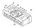
図7はフロントホルダ28を示す要部切欠斜視図であり、上壁44とランス撓み阻止用の板壁41との間に前記アーム受け部5が一体に形成されている。アーム受け部5は、端子挿入方向ないしホルダ挿入方向に真直に延びる矩形柱状の受け部本体14と、受け部本体14の先端両側に分離して設けられた仮係合突起15と本係合突起16とで構成されている。
【0055】
アーム受け部5の一側方に、受け部本体14と平行な真直面20と短い傾斜面19とを有する第一のアームガイド部6が形成され、アーム受け部5の他側方に、長い傾斜面21と短い真直面22とを有する第二のアームガイド部7が形成されている。アーム受け部5と各アームガイド部6,7とは上壁44と板壁41とを垂直に連結する各壁部として形成されている。
【0056】
フロントホルダ28を前記コネクタハウジング27内に弱く押し込むことで、アーム受け部5の仮係合突起15と仮係止アーム3の仮係止突起8とで図5の如くフロントホルダ28がコネクタハウジング27に確実に仮係止され、その状態で端子29を挿入係止させ、次いでフロントホルダ28を端子挿入反対方向に強く押し込むことで、アーム受け部5の本係合突起16と本係止アーム4の本係止突起12とでフロントホルダ28が強い係止力で確実に本係止される。
【0057】
上記図5〜図7は雄型のコネクタ26に係止構造を適用した例であり、雌型のコネクタ(図示せず)に係止構造を適用する場合には、例えばハウジング主体部33の上壁34は用いずに、垂直な基壁45から一対の係止アーム3,4を水平に突出形成し、フロントホルダ28のアーム受け部5は上壁を切欠した空間内において板壁41上に一体に形成する。これら係止アーム3,4やアーム受け部5及びアームガイド部6,7の構成はあくまでも一例であり、コネクタハウジング27やフロントホルダ28といった物品の形態に応じて適宜設定可能である。
【0058】
また、図1においてフロントホルダ2に一対の係止アーム3,4を設け、コネクタハウジング1にアーム受け部5とアームガイド部6,7とを設けることも可能である。また、図1の係止構造はコネクタハウジング1やフロントホルダ2以外にも図示しない電気接続箱やスペーサやリヤホルダ等にも適用可能である。
【0059】
【発明の効果】
以上の如く、請求項1記載の発明によれば、両物品の本係止に際して、本係止アームの先端外側部がアームガイド部の傾斜部に接して、本係止アームが傾斜した状態に両持ち支持される(片持ち支持から両持ち支持に移行する)から、本係止アームを撓ませるに要する力が増大し、仮係止よりも本係止させるのに大きな力が必要となる。これにより、物品の搬送中等での仮係止から本係止への不意な移行が防止される。これにより、従来の面倒な手直し作業(不意な本係止を仮係止に戻す作業)が排除される。また、本係止アームが両持ち支持されることで、本係止の解除に仮係止の解除よりも大きな力を必要とするから、本係止の不意な解除が防止され、両物品が強い力で固定される。これにより、車両の振動等による両物品の本係止外れが防止される。また、一対の係止アームと、両係止アームの間に進入するアーム受け部と、一対のアームガイド部という構成により、従来の係止アームの中空部が不要となり、樹脂成形時の金型の無理抜きが可能となり、金型の構造が簡素化されて、製造が低コスト化される。
【0060】
請求項2記載の発明によれば、仮係止アームの仮係止部がアーム受け部の仮係合部に乗り越えて係合すると同時に、本係止アームの本係止部がアーム受け部の本係合部に当接して、ガタ付きなく確実に仮係止状態が得られるから、製品の価値が向上する。
【0061】
請求項3記載の発明によれば、仮係止に際して仮係止アームが外側に撓みつつ、仮係止アームの先端外側の傾斜部が他方のアームガイド部の先端内側の傾斜部に沿ってスムーズに通過するから、仮係止が小さな力で容易に行われる。これにより、仮係止性が向上する。
【0062】
請求項4記載の発明によれば、仮係止に際して仮係止部と仮係合部との係合と、本係止部と本係合部との当接とが確実に行われ、また、本係止に際して仮係止部がアーム受け部に沿って真直にスムーズに移動し、本係止部が本係合部に確実に係合するから、仮係止性及び本係止性が向上する。
【0063】
請求項5記載の発明によれば、コネクタハウジングへのフロントホルダの仮係止から本係止への移行を仮係止よりも大きな力で行うことで、フロントホルダの不意な押し込み(本係止)が防止され、且つ本係止の不意な解除が防止される。これにより、フロントホルダの仮係止状態でコネクタハウジング内への端子の挿入をスムーズに行うことができ、且つフロントホルダの本係止時にコネクタハウジング内の端子の位置ずれが防止され、相手コネクタとの電気的接続の信頼性が高まる。
【図面の簡単な説明】
【図1】本発明に係る二物品の係止構造の一実施形態を示す平面図である。
【図2】同じく仮係止状態を示す平面図である。
【図3】同じく仮係止から本係止に移行する途中の状態を示す平面図である。
【図4】同じく本係止状態を示す平面図である。
【図5】上記二物品の係止構造を適用したホルダ付きコネクタの一形態を示す縦断面図である。
【図6】同じくコネクタハウジングの一形態を示す正面図である。
【図7】同じくフロントホルダの一形態を示す要部切欠斜視図である。
【図8】従来のホルダ付きコネクタの一形態を示す縦断面図である。
【図9】従来の二物品の係止構造の一形態の仮係止状態を示す平面図である。
【図10】同じく本係止状態を示す平面図である。
【符号の説明】
1 一方の物品(コネクタハウジング)
2 他方の物品(フロントホルダ)
3 仮係止アーム
4 本係止アーム
5 アーム受け部
6,7 アームガイド部
8 仮係止突起(仮係止部)
11a 先端外側部(先端)
12 本係止突起(本係止部)
15 仮係合突起(仮係合部)
16 本係合部(本係合突起)
9,19 傾斜面(傾斜部)
21 傾斜面(傾斜部)
30 端子収容室[0001]
BACKGROUND OF THE INVENTION
The present invention relates to a locking structure for two articles for temporarily locking and permanently locking a connector housing and a front holder, for example.
[0002]
[Prior art]
FIG. 8 shows one form of a conventional connector with a holder.
The connector with
[0003]
The
[0004]
The
[0005]
The
[0006]
By forming the
[0007]
Various types of means for locking the
[0008]
In FIG. 9,
[0009]
As shown in FIG. 9, in a state where the
[0010]
In the next step, the front holder 62 is completely pushed in as shown in FIG. The
[0011]
[Problems to be solved by the invention]
However, in the above conventional locking structure of the connector with a holder, the pushing force required to temporarily lock the front holder 62 and the pushing force required to fully lock the front holder 62 are substantially the same. In addition, for example, in an automatic assembly machine or the like, when the front holder 62 is transported in a state of being temporarily locked to the
[0012]
In addition, it is ideal that the front holder 62 can be easily temporarily locked and the final locking can be surely performed with a strong force, but conventionally, the front locking force of the front holder 62 is weak and the front There is a problem that the holder 62 is easily detached unexpectedly due to vibration or the like during traveling of the vehicle.
[0013]
Further, since a slit-like hole (hollow part) 69 for bending must be provided at the center in the width direction of the
[0014]
In addition to the locking of the front holder 62 described above, the temporary locking means and the main locking means are necessary when inserting a double terminal locking spacer or the like into a connector or an electrical connection box, for example. In these cases, the above-mentioned problems can occur.
[0015]
In view of the above-described points, the present invention does not cause a main locking unexpectedly when two articles such as a front holder and a connector housing are temporarily locked with each other, and the main locking is strong. An object of the present invention is to provide a two-article locking structure that can be reliably performed with force and that can easily and inexpensively perform resin molding.
[0016]
[Means for Solving the Problems]
In order to achieve the above object, the two article locking structure according to
[0017]
With the above configuration, the temporary locking arm is first engaged with the temporary engagement portion of the arm receiving portion, both articles are temporarily locked, and then one and / or the other article is further pushed in the assembly direction. The main locking arm bends outward while riding on the main engagement portion of the arm receiving portion, and the outer end of the main locking arm is in contact with the inclined portion of the arm guide portion so that the main locking arm is tilted. Supported. As a result, the force required to bend the main locking arm is increased, and a larger force is required to make the main locking than the temporary locking. This prevents an unexpected transition from temporary locking to full locking. Both articles are finally locked by the main locking arm getting over and engaging the main engaging portion. When releasing the main locking, the outer end of the main locking arm is in contact with the inclined portion of the arm guide portion and the main locking arm is supported at both ends in the same manner as described above. Even requires great power. This prevents unexpected release of the main lock. Further, since the pair of locking arms advance and retract while being guided along the arm guide portions on both sides and the central arm receiving portion, the positions of the pair of locking arms are accurately defined, and an accurate temporary locking force can be obtained. This locking force is obtained.
[0018]
The two article locking structure according to
[0019]
With the above configuration, the temporary locking portion of the temporary locking arm climbs over and engages with the temporary engagement portion of the arm receiving portion, and at the same time, the final locking portion of the final locking arm contacts the main engagement portion of the arm receiving portion. In contact with each other, the temporarily locked state can be reliably obtained without rattling.
[0020]
The two-article locking structure according to
[0021]
With the above configuration, when the temporary locking portion of the temporary locking arm rides on the temporary engagement portion of the arm receiving portion and the temporary locking arm bends outward, the inclined portion on the outer end of the temporary locking arm is The other arm guide portion passes smoothly along the inclined portion on the inner side of the tip, and the temporary locking is easily performed with a small force.
[0022]
The locking structure for two articles according to
[0023]
With the above configuration, the provisional engagement between the temporary engagement portion and the temporary engagement portion and the contact between the final engagement portion and the main engagement portion are reliably performed during temporary engagement. Further, during the final locking, the temporary locking portion moves straight and smoothly along the arm receiving portion, and the main locking portion reliably engages with the main engagement portion.
[0024]
The two article locking structure according to
[0025]
With the above configuration, the transition from the temporary locking of the front holder to the connector housing to the final locking is performed with a force larger than that of the temporary locking, and the unexpected push-in (main locking) of the front holder is prevented. In addition, unintentional release of the main lock is prevented.
[0026]
DETAILED DESCRIPTION OF THE INVENTION
Embodiments of the present invention will be described below in detail with reference to the drawings.
1 to 4 show an embodiment of a locking structure for two articles according to the present invention.
[0027]
As shown in FIG. 1, this structure is provided on a pair of left and right flexible
[0028]
The
[0029]
The other
[0030]
A
[0031]
The
[0032]
The
[0033]
The
[0034]
The outward projecting lengths of the temporary
[0035]
The first
[0036]
The first
[0037]
The second
[0038]
In FIG. 1, when the
[0039]
At the same time, as shown in FIG. 2, the
[0040]
2, when both
[0041]
That is, the
[0042]
Further, by further pushing the relative push-in of the
[0043]
The
[0044]
Then, the main locking state of FIG. 4 is reached, and the
[0045]
When a force for releasing the main locking is applied to both
[0046]
When it is desired to release the main locking, the main locking is released by pulling the
[0047]
According to this embodiment, in addition to the improvement of the main locking force, an intermediate bending hole as in the conventional locking arm is unnecessary, so that the locking
[0048]
Hereinafter, an application example of the locking structure shown in FIGS. 1 to 4 will be described with reference to FIGS.
[0049]
FIG. 5 shows an embodiment of a connector with a holder. The connector with a
[0050]
The
[0051]
The
[0052]
As a locking structure for the
[0053]
FIG. 6 is a front view showing the
[0054]
FIG. 7 is a cutaway perspective view of the main part showing the
[0055]
A first
[0056]
By pushing the
[0057]
FIGS. 5 to 7 are examples in which the locking structure is applied to the
[0058]
In FIG. 1, a pair of locking
[0059]
【The invention's effect】
As described above, according to the first aspect of the present invention, when the two articles are finally locked, the distal end outer portion of the locking arm is in contact with the inclined portion of the arm guide portion so that the locking arm is inclined. Since both ends are supported (shift from cantilever support to both ends support), the force required to bend the main locking arm is increased, and a larger force is required to make the main locking than the temporary locking. . This prevents an unexpected transition from temporary locking to permanent locking during conveyance of the article. As a result, the conventional troublesome reworking work (work for returning the unexpected permanent lock to the temporary lock) is eliminated. In addition, since the main locking arm is supported at both ends, a greater force is required to release the main locking than to release the temporary locking. Fixed with strong force. As a result, it is possible to prevent the main article from being released due to vibrations of the vehicle. In addition, the structure of a pair of locking arms, an arm receiving portion that enters between both locking arms, and a pair of arm guide portions eliminates the need for a hollow portion of a conventional locking arm, and molds during resin molding Therefore, the mold structure is simplified and the manufacturing cost is reduced.
[0060]
According to the second aspect of the invention, the temporary locking portion of the temporary locking arm climbs over and engages with the temporary engagement portion of the arm receiving portion, and at the same time, the final locking portion of the final locking arm is The value of the product is improved because it is brought into contact with the main engaging portion and a temporarily locked state can be reliably obtained without rattling.
[0061]
According to the third aspect of the present invention, the temporary locking arm bends outward during temporary locking, and the inclined portion on the outer end of the temporary locking arm is smooth along the inclined portion on the inner side of the other arm guide portion. Therefore, the temporary locking is easily performed with a small force. Thereby, temporary latching property improves.
[0062]
According to the fourth aspect of the present invention, during temporary locking, the engagement between the temporary locking portion and the temporary engaging portion and the contact between the main locking portion and the main engaging portion are reliably performed. Since the temporary locking portion moves straight and smoothly along the arm receiving portion during the final locking and the main locking portion securely engages with the main engagement portion, the temporary locking property and the main locking property are improves.
[0063]
According to the invention described in
[Brief description of the drawings]
FIG. 1 is a plan view showing an embodiment of a locking structure for two articles according to the present invention.
FIG. 2 is a plan view showing a temporarily locked state.
FIG. 3 is a plan view showing a state in the middle of the transition from temporary locking to full locking.
FIG. 4 is a plan view showing the final locking state.
FIG. 5 is a longitudinal sectional view showing an embodiment of a connector with a holder to which the two article locking structure is applied.
FIG. 6 is a front view showing another embodiment of the connector housing.
FIG. 7 is a cutaway perspective view of an essential part showing an embodiment of the front holder.
FIG. 8 is a longitudinal sectional view showing one embodiment of a conventional connector with a holder.
FIG. 9 is a plan view showing a temporary locking state of one form of a conventional two-article locking structure.
FIG. 10 is a plan view showing the final locking state.
[Explanation of symbols]
1 One article (connector housing)
2 The other article (front holder)
3 Temporary locking arm
4 locking arms
5 Arm receiver
6,7 Arm guide part
8 Temporary locking projection (temporary locking part)
11a Tip outer side (tip)
12 locking projections (locking part)
15 Temporary engagement protrusion (temporary engagement portion)
16 engagement parts (main engagement protrusions)
9,19 Inclined surface (inclined part)
21 Inclined surface (inclined part)
30 Terminal compartment
Claims (5)
Priority Applications (5)
| Application Number | Priority Date | Filing Date | Title |
|---|---|---|---|
| JP2001232009A JP3717814B2 (en) | 2001-07-31 | 2001-07-31 | Two article locking structure |
| DE60206854T DE60206854T2 (en) | 2001-07-31 | 2002-07-31 | Locking device for two pieces |
| KR10-2002-0045163A KR100454601B1 (en) | 2001-07-31 | 2002-07-31 | Structure for locking two workpieces |
| US10/207,766 US6669510B2 (en) | 2001-07-31 | 2002-07-31 | Structure for locking two workpieces |
| EP02017243A EP1282200B1 (en) | 2001-07-31 | 2002-07-31 | Structure for locking two workpieces |
Applications Claiming Priority (1)
| Application Number | Priority Date | Filing Date | Title |
|---|---|---|---|
| JP2001232009A JP3717814B2 (en) | 2001-07-31 | 2001-07-31 | Two article locking structure |
Publications (2)
| Publication Number | Publication Date |
|---|---|
| JP2003045546A JP2003045546A (en) | 2003-02-14 |
| JP3717814B2 true JP3717814B2 (en) | 2005-11-16 |
Family
ID=19063988
Family Applications (1)
| Application Number | Title | Priority Date | Filing Date |
|---|---|---|---|
| JP2001232009A Expired - Fee Related JP3717814B2 (en) | 2001-07-31 | 2001-07-31 | Two article locking structure |
Country Status (5)
| Country | Link |
|---|---|
| US (1) | US6669510B2 (en) |
| EP (1) | EP1282200B1 (en) |
| JP (1) | JP3717814B2 (en) |
| KR (1) | KR100454601B1 (en) |
| DE (1) | DE60206854T2 (en) |
Cited By (1)
| Publication number | Priority date | Publication date | Assignee | Title |
|---|---|---|---|---|
| JP2014107011A (en) * | 2012-11-22 | 2014-06-09 | Omron Corp | Earth terminal and connector using the same |
Families Citing this family (33)
| Publication number | Priority date | Publication date | Assignee | Title |
|---|---|---|---|---|
| US7118658B2 (en) | 2002-05-21 | 2006-10-10 | Semitool, Inc. | Electroplating reactor |
| NL1023937C2 (en) * | 2003-07-17 | 2005-01-18 | Framatome Connectors Int | Locking element. |
| JP2005056717A (en) * | 2003-08-05 | 2005-03-03 | Tyco Electronics Amp Kk | Ic socket |
| US8109883B2 (en) | 2006-09-28 | 2012-02-07 | Tyco Healthcare Group Lp | Cable monitoring apparatus |
| US8668651B2 (en) | 2006-12-05 | 2014-03-11 | Covidien Lp | ECG lead set and ECG adapter system |
| DE102006060238A1 (en) * | 2006-12-20 | 2008-06-26 | Hirschmann Automotive Gmbh | Plug connection, consisting of a plug and a coupler with a contact carrier and a protective collar |
| US8038484B2 (en) | 2007-12-11 | 2011-10-18 | Tyco Healthcare Group Lp | ECG electrode connector |
| USD737979S1 (en) | 2008-12-09 | 2015-09-01 | Covidien Lp | ECG electrode connector |
| US8769782B2 (en) | 2009-09-29 | 2014-07-08 | Yazaki Corporation | Resin molded parts lock mechanism |
| US8694080B2 (en) | 2009-10-21 | 2014-04-08 | Covidien Lp | ECG lead system |
| CA2746944C (en) | 2010-07-29 | 2018-09-25 | Tyco Healthcare Group Lp | Ecg adapter system and method |
| JP5565184B2 (en) * | 2010-08-06 | 2014-08-06 | 住友電装株式会社 | connector |
| JP2012216343A (en) | 2011-03-31 | 2012-11-08 | Sumitomo Wiring Syst Ltd | Connector |
| JP2013016402A (en) * | 2011-07-06 | 2013-01-24 | Sumitomo Wiring Syst Ltd | Connector |
| JP5739757B2 (en) | 2011-07-19 | 2015-06-24 | 矢崎総業株式会社 | connector |
| CN103687537B (en) | 2011-07-22 | 2016-02-24 | 柯惠有限合伙公司 | Ecg electrode connector |
| US8634901B2 (en) | 2011-09-30 | 2014-01-21 | Covidien Lp | ECG leadwire system with noise suppression and related methods |
| JP6138428B2 (en) * | 2012-05-29 | 2017-05-31 | 矢崎総業株式会社 | connector |
| JP2012230927A (en) * | 2012-08-30 | 2012-11-22 | Delphi Automotive Systems Japan Ltd | Connector |
| EP2967396B1 (en) | 2013-03-15 | 2019-02-13 | Kpr U.S., Llc | Electrode connector with a conductive member |
| US9408546B2 (en) | 2013-03-15 | 2016-08-09 | Covidien Lp | Radiolucent ECG electrode system |
| USD771818S1 (en) | 2013-03-15 | 2016-11-15 | Covidien Lp | ECG electrode connector |
| US9917398B1 (en) * | 2013-03-21 | 2018-03-13 | Barobo, Inc. | Mechanical snap connector assembly |
| DE102013219459A1 (en) | 2013-09-26 | 2015-03-26 | Tyco Electronics Amp Gmbh | plug-in device |
| JP6015628B2 (en) * | 2013-10-31 | 2016-10-26 | 住友電装株式会社 | connector |
| JP6652574B2 (en) | 2015-04-09 | 2020-02-26 | フェニックス コンタクト ディベロップメント アンド マニュファクチャリング、インコーポレイテッド | Electronic module extraction feedback system |
| JP6402125B2 (en) * | 2016-03-03 | 2018-10-10 | 矢崎総業株式会社 | connector |
| JP6944331B2 (en) * | 2017-05-18 | 2021-10-06 | モレックス エルエルシー | Connector and connector assembly. |
| JP2019050169A (en) * | 2017-09-12 | 2019-03-28 | 住友電装株式会社 | connector |
| JP6754389B2 (en) | 2018-04-04 | 2020-09-09 | 矢崎総業株式会社 | connector |
| JP6839146B2 (en) * | 2018-09-03 | 2021-03-03 | 矢崎総業株式会社 | connector |
| KR102622133B1 (en) * | 2019-05-15 | 2024-01-08 | 현대모비스 주식회사 | Double lock connector for vehicle |
| CN110694284B (en) * | 2019-09-23 | 2021-12-31 | 深圳市优必选科技股份有限公司 | Building block toy and connecting assembly thereof |
Family Cites Families (9)
| Publication number | Priority date | Publication date | Assignee | Title |
|---|---|---|---|---|
| FR2636785B1 (en) * | 1988-09-20 | 1990-11-02 | Labinal | IMPROVEMENTS ON ELECTRICAL CONNECTION BOXES |
| FR2669897B1 (en) * | 1990-11-30 | 1993-01-22 | Labinal | DEVICE FOR LOCKING TWO HOUSING ELEMENTS IN RELATION TO THE OTHER. |
| JP2904377B2 (en) * | 1992-07-29 | 1999-06-14 | 矢崎総業株式会社 | Connector locking mechanism |
| JP2932902B2 (en) | 1993-08-03 | 1999-08-09 | 住友電装株式会社 | connector |
| US5931700A (en) * | 1995-02-06 | 1999-08-03 | Yazaki Corporation | Connector equipped with an insertion detecting member for terminal lugs |
| US5716234A (en) * | 1996-10-03 | 1998-02-10 | General Motors Corporation | Electrical connector with positive lock retention |
| JP3420918B2 (en) * | 1997-09-17 | 2003-06-30 | 矢崎総業株式会社 | Half mating prevention connector |
| FR2774816B1 (en) * | 1998-02-11 | 2004-02-20 | Cinch Connecteurs Sa | ELECTRICAL CONNECTOR HOUSING ELEMENT |
| JP3467185B2 (en) * | 1998-04-08 | 2003-11-17 | 矢崎総業株式会社 | Connector locking mechanism |
-
2001
- 2001-07-31 JP JP2001232009A patent/JP3717814B2/en not_active Expired - Fee Related
-
2002
- 2002-07-31 US US10/207,766 patent/US6669510B2/en not_active Expired - Lifetime
- 2002-07-31 EP EP02017243A patent/EP1282200B1/en not_active Expired - Fee Related
- 2002-07-31 DE DE60206854T patent/DE60206854T2/en not_active Expired - Lifetime
- 2002-07-31 KR KR10-2002-0045163A patent/KR100454601B1/en active IP Right Grant
Cited By (1)
| Publication number | Priority date | Publication date | Assignee | Title |
|---|---|---|---|---|
| JP2014107011A (en) * | 2012-11-22 | 2014-06-09 | Omron Corp | Earth terminal and connector using the same |
Also Published As
| Publication number | Publication date |
|---|---|
| DE60206854D1 (en) | 2005-12-01 |
| US20030027456A1 (en) | 2003-02-06 |
| EP1282200B1 (en) | 2005-10-26 |
| EP1282200A2 (en) | 2003-02-05 |
| KR100454601B1 (en) | 2004-11-03 |
| US6669510B2 (en) | 2003-12-30 |
| KR20030013253A (en) | 2003-02-14 |
| JP2003045546A (en) | 2003-02-14 |
| DE60206854T2 (en) | 2006-07-27 |
| EP1282200A3 (en) | 2004-01-28 |
Similar Documents
| Publication | Publication Date | Title |
|---|---|---|
| JP3717814B2 (en) | Two article locking structure | |
| KR100973020B1 (en) | A terminal fitting, a connector and a forming method | |
| JP2006253017A (en) | Joint connector | |
| US7267569B2 (en) | Connector with a shorting terminal | |
| JP3000869B2 (en) | connector | |
| JPH07114134B2 (en) | Connector with terminal locking device | |
| US6896560B2 (en) | Connector with retainer having front wall and reinforcement | |
| JP3337008B2 (en) | connector | |
| JP2567848Y2 (en) | connector | |
| JP4306608B2 (en) | Split connector | |
| JP3687537B2 (en) | Split connector | |
| US6835105B1 (en) | Connector and method of connecting a connector with a mating connector | |
| JPH0945411A (en) | Connector with holder | |
| JP2003045544A (en) | Terminal-locking structure of connector | |
| JP2000138084A (en) | Connector | |
| JPH10223312A (en) | Connector device | |
| JP2006202536A (en) | Connector | |
| JP3752961B2 (en) | connector | |
| JP6358102B2 (en) | connector | |
| JP3123436B2 (en) | connector | |
| JP3466366B2 (en) | connector | |
| JP4450462B2 (en) | Locking structure of rear holder for electrical connector | |
| JP5304606B2 (en) | Lock structure | |
| JP2001319732A (en) | Connector | |
| JP3466367B2 (en) | connector |
Legal Events
| Date | Code | Title | Description |
|---|---|---|---|
| A977 | Report on retrieval |
Free format text: JAPANESE INTERMEDIATE CODE: A971007 Effective date: 20040804 |
|
| A131 | Notification of reasons for refusal |
Free format text: JAPANESE INTERMEDIATE CODE: A131 Effective date: 20050215 |
|
| A521 | Written amendment |
Free format text: JAPANESE INTERMEDIATE CODE: A523 Effective date: 20050418 |
|
| TRDD | Decision of grant or rejection written | ||
| A01 | Written decision to grant a patent or to grant a registration (utility model) |
Free format text: JAPANESE INTERMEDIATE CODE: A01 Effective date: 20050823 |
|
| A61 | First payment of annual fees (during grant procedure) |
Free format text: JAPANESE INTERMEDIATE CODE: A61 Effective date: 20050831 |
|
| R150 | Certificate of patent or registration of utility model |
Ref document number: 3717814 Country of ref document: JP Free format text: JAPANESE INTERMEDIATE CODE: R150 Free format text: JAPANESE INTERMEDIATE CODE: R150 |
|
| FPAY | Renewal fee payment (event date is renewal date of database) |
Free format text: PAYMENT UNTIL: 20090909 Year of fee payment: 4 |
|
| FPAY | Renewal fee payment (event date is renewal date of database) |
Free format text: PAYMENT UNTIL: 20100909 Year of fee payment: 5 |
|
| FPAY | Renewal fee payment (event date is renewal date of database) |
Free format text: PAYMENT UNTIL: 20100909 Year of fee payment: 5 |
|
| FPAY | Renewal fee payment (event date is renewal date of database) |
Free format text: PAYMENT UNTIL: 20110909 Year of fee payment: 6 |
|
| FPAY | Renewal fee payment (event date is renewal date of database) |
Free format text: PAYMENT UNTIL: 20120909 Year of fee payment: 7 |
|
| FPAY | Renewal fee payment (event date is renewal date of database) |
Free format text: PAYMENT UNTIL: 20120909 Year of fee payment: 7 |
|
| FPAY | Renewal fee payment (event date is renewal date of database) |
Free format text: PAYMENT UNTIL: 20130909 Year of fee payment: 8 |
|
| R250 | Receipt of annual fees |
Free format text: JAPANESE INTERMEDIATE CODE: R250 |
|
| R250 | Receipt of annual fees |
Free format text: JAPANESE INTERMEDIATE CODE: R250 |
|
| R250 | Receipt of annual fees |
Free format text: JAPANESE INTERMEDIATE CODE: R250 |
|
| R250 | Receipt of annual fees |
Free format text: JAPANESE INTERMEDIATE CODE: R250 |
|
| LAPS | Cancellation because of no payment of annual fees |