EP2736070A1 - Vessel for the one-sided processing a substrate - Google Patents
Vessel for the one-sided processing a substrate Download PDFInfo
- Publication number
- EP2736070A1 EP2736070A1 EP12194373.2A EP12194373A EP2736070A1 EP 2736070 A1 EP2736070 A1 EP 2736070A1 EP 12194373 A EP12194373 A EP 12194373A EP 2736070 A1 EP2736070 A1 EP 2736070A1
- Authority
- EP
- European Patent Office
- Prior art keywords
- vessel
- substrate
- liquid
- volume
- processing
- Prior art date
- Legal status (The legal status is an assumption and is not a legal conclusion. Google has not performed a legal analysis and makes no representation as to the accuracy of the status listed.)
- Withdrawn
Links
Images




Classifications
-
- H—ELECTRICITY
- H10—SEMICONDUCTOR DEVICES; ELECTRIC SOLID-STATE DEVICES NOT OTHERWISE PROVIDED FOR
- H10P—GENERIC PROCESSES OR APPARATUS FOR THE MANUFACTURE OR TREATMENT OF DEVICES COVERED BY CLASS H10
- H10P72/00—Handling or holding of wafers, substrates or devices during manufacture or treatment thereof
- H10P72/04—Apparatus for manufacture or treatment
- H10P72/0402—Apparatus for fluid treatment
- H10P72/0418—Apparatus for fluid treatment for etching
- H10P72/0422—Apparatus for fluid treatment for etching for wet etching
-
- H—ELECTRICITY
- H10—SEMICONDUCTOR DEVICES; ELECTRIC SOLID-STATE DEVICES NOT OTHERWISE PROVIDED FOR
- H10P—GENERIC PROCESSES OR APPARATUS FOR THE MANUFACTURE OR TREATMENT OF DEVICES COVERED BY CLASS H10
- H10P72/00—Handling or holding of wafers, substrates or devices during manufacture or treatment thereof
- H10P72/04—Apparatus for manufacture or treatment
- H10P72/0402—Apparatus for fluid treatment
- H10P72/0418—Apparatus for fluid treatment for etching
- H10P72/0422—Apparatus for fluid treatment for etching for wet etching
- H10P72/0426—Apparatus for fluid treatment for etching for wet etching with the semiconductor substrates being dipped in baths or vessels
-
- H—ELECTRICITY
- H10—SEMICONDUCTOR DEVICES; ELECTRIC SOLID-STATE DEVICES NOT OTHERWISE PROVIDED FOR
- H10P—GENERIC PROCESSES OR APPARATUS FOR THE MANUFACTURE OR TREATMENT OF DEVICES COVERED BY CLASS H10
- H10P72/00—Handling or holding of wafers, substrates or devices during manufacture or treatment thereof
- H10P72/10—Handling or holding of wafers, substrates or devices during manufacture or treatment thereof using carriers specially adapted therefor, e.g. front opening unified pods [FOUP]
- H10P72/18—Handling or holding of wafers, substrates or devices during manufacture or treatment thereof using carriers specially adapted therefor, e.g. front opening unified pods [FOUP] characterised by being specially adapted for supporting a single substrate or by comprising a stack of such individual supports
Definitions
- the invention relates to a vessel for one-sided processing of a substrate and a corresponding method.
- wet-chemical etching or cleaning takes place. Due to the process sequence, it may sometimes be necessary to process a substrate (for example, a so-called wafer) with wet-chemical only on one side.
- a substrate for example, a so-called wafer
- the side to be processed must be brought into contact with the wet-chemical liquid and, on the other hand, the side which is not to be processed must be protected from the wet-chemical liquid. To do this, the non-editable page must be encapsulated.
- US 5,324,410 describes such an encapsulation of a substrate to be processed (silicon wafer) from a bottom part and an annular cover, between which the substrate is positioned on respective O-rings.
- the bottom part is hermetically closed. Lid and bottom part have screw holes, can be used in the locking screws, so that the lid and bottom part can be pressed apart. Due to the pressure thus exerted, the O-rings seal the side of the substrate facing the bottom part in a liquid-tight manner.
- the etching process machining
- the etching liquid is then placed in an etching bath so that the etching liquid can cover the encapsulation and flow through the opening of the annular cover to the top side of the substrate for processing this side.
- a vessel for one-sided processing of a substrate having a lower vessel part and a vessel upper part arranged on the vessel lower part for holding the substrate, wherein the vessel upper part comprises an upper part volume for receiving a surface-engaging liquid for processing the substrate, which has at least one filling opening in the vessel upper part in the Upper part volume can be inserted, wherein the lower part of the vessel on the upper side facing the vessel upper surface suitably adapted for the substrate comprises a first support surface and the vessel upper part on the side facing the vessel lower part suitable for the substrate adapted second support surface, wherein the first and second bearing surfaces and the Molds of the vessel bottom and the vessel top are designed so that the positioned between the first and second bearing surfaces substrate can be supported liquid-tight, so that the surface-engaging liquid can not get from the side to be processed of the substrate to another side of the substrate and the shell volume a has sufficient size to receive an amount of surface-engaging liquid needed for processing and to store it during processing of the substrate, wherein a lower limit of the shell volume is determined
- the term "vessel” refers to all bodies in which at least one surface-engaging liquid can be filled and stored over a period of time. For one-sided processing of a substrate, the surface-engaging liquid is filled only from one side of the vessel and stored only in the area which has access only to one side of the substrate.
- surface attacking liquid refers to all liquids with which the surface of a substrate can be processed, for example a corrosive liquid for processing a silicon substrate (silicon wafer).
- processing and “processing” refer to wet chemical processes that alter, for example, clean, roughen, chemically modify, or otherwise alter the machined surface of the substrate.
- substrate refers to all bodies that are provided for wet-chemical processing on their surface by means of a surface-engaging liquid. These bodies do not necessarily have to be disc-shaped, but the body in the region of the bearing surfaces must be designed in such a way that it can be held in a liquid-tight manner by means of pressing surfaces resting on one another. Here, the bearing surfaces of the shape of the body can be adjusted accordingly.
- the substrate is disk-shaped. In this case, the first and second bearing surfaces are arranged at least substantially parallel to one another. If the vessel according to the invention is configured without sealing rings, the bearing surfaces are arranged plane-parallel to each other in the case of a disc-shaped substrate.
- the substrate may have any geometric shapes.
- a disk-shaped substrate may have a substantially constant thickness, it may be circular, rectangular, square, hexagonal, or other in shape.
- the vessel from the upper vessel part and lower vessel part, in particular the first and second bearing surfaces are designed so that the substrate provided for them can be held liquid-tight.
- the first and second bearing surfaces are preferably also circular. The same applies analogously to the other possible forms of the substrate (rectangular substrate - rectangular bearing surfaces, ).
- Suitable resistant materials for the vessel top, at least for the first region are, for example, polyethylene (PE) and polypropylene (PP), which are sufficiently resistant to many of the surface-attacking fluids used.
- PE polyethylene
- PP polypropylene
- the use of ceramics or metal is possible.
- quartz glass can be well used for the surface-engaging liquids (b) and (c).
- PTFE can be used as the material for the vessel top part or for the first area for all surface-attacking liquids mentioned above.
- the term "sufficiently resistant” refers to a material that makes it possible to process several hundred substrates with surface-engaging liquid before the surface of the shell volume itself is chemically attacked so that no more sufficient sealing effect against the surface-attacking liquid is given or the quality of Processing of the substrate is no longer acceptable.
- the material of the first area of the Upper part of the vessel so chemically resistant that it is not attacked by the surface-attacking liquid such as quartz glass (exception: hydrofluoric acid).
- a particularly resitent material to the surface-attacking fluids used is PTFE (polytetrafluoroethylene, sometimes called polytetrafluoroethene).
- this material is not heated above 200 °, more than a thousand, possibly several thousand substrate treatments can be made without this material being attacked by the surface-engaging liquids themselves for substrate processing.
- an expensive chemically resistant material for example PTFE, ceramic, glass or metal
- the remaining region of the vessel upper part is made of a simple material ,
- urea resin as a simple plastic may exist, for example, allows a less expensive injection molding production.
- the first region is reversibly supported in the vessel top suitable for replacement with another first region.
- the first region has a suitable shape that allows a reversible holder, for example, a symmetrical shape with a circular cross-section (inside hollow cylindrical shape) or a rectangular cross-section (inside hollow cuboid shape) in a cylindrical or cuboid vessel top.
- a suitable shape that allows a reversible holder, for example, a symmetrical shape with a circular cross-section (inside hollow cylindrical shape) or a rectangular cross-section (inside hollow cuboid shape) in a cylindrical or cuboid vessel top.
- the person skilled in the art can also select other suitable shapes of the first region adapted to the shape of the vessel upper part.
- the first region can be held, for example, by a press fit by means of sufficient frictional forces in the rest of the vessel upper part, which surrounds the first region in an interference fit.
- a first region of a material (particularly resistant material) which is particularly suitable for the respective surface-engaging liquid used can always be used for the following Substrate processing can be selected.
- it can be avoided by replacing the first area that the complete upper vessel part would have to be replaced at a worn first area. As a result, material costs can be avoided and good process quality can be ensured during substrate processing.
- the lower vessel part serves as a carrier for the substrate, wherein the first bearing surface of the vessel base in cooperation with the second bearing surface and the substrate produces a sealing action against the surface-engaging liquid, so that no surface-attacking liquid can reach the other side of the substrate.
- the sealing effect can be achieved in the context of the present invention by various sealing mechanisms.
- a sealing mechanism a press fit of the vessel top can be used on the vessel bottom, in which the first and second bearing surfaces are pressed together (exerting a contact pressure), so that the substrate is liquid-tightly enclosed and the vessel upper part remains in its position due to the press fit for the machining operation.
- the shapes of the upper vessel part and the lower vessel part must be adapted to each other so that the upper vessel part can be pushed with pressure on the lower vessel part.
- the upper vessel part can also be screwed onto the vessel lower part.
- Other seal mechanisms for exerting a contact pressure on the first and second contact surfaces within the scope of the present invention may be selected by a person skilled in the art.
- the vessel for processing a substrate can be put into operation quickly and with little effort.
- the other side here is the area which should not be processed by the surface-attacking liquid. It is therefore not excluded in principle, depending on the selected sealing mechanism, that the surface-engaging liquid the edge of the substrate or the other side of the substrate in the edge region reached.
- the sealing mechanism must only prevent the surface-engaging liquid from reaching the areas of the other side of the substrate that are not to be processed by the surface-engaging liquid. Only these regions are referred to as the other side in the present invention.
- the lower part of the vessel is not or only to a very small extent with the surface-engaging liquid in contact.
- at least the first bearing surface comprises a sealing ring for this purpose.
- the sealing mechanism between the first and second support surface is designed such that the vessel lower part does not come into contact with the surface-engaging liquid. In this case, the vessel bottom does not have to be made of a material which is chemically resistant to the surface attacking liquid.
- the vessel lower part may be made of a less expensive material, for example a simple plastic such as urea resin.
- the first bearing surface comprises a sealing ring or the first bearing surface and the second bearing surface both comprise a sealing ring.
- a plurality of sealing rings per support surface may be used.
- these sealing rings are arranged one above the other in the printing direction in order to avoid stresses in the substrate during processing and / or to further enhance the sealing effect of the sealing ring in / on the second support surface.
- the sealing ring may have any suitable shape, for example, the sealing ring may have a cylindrical or rectangular cross-section.
- the circumferential shape of the sealing ring is adapted to the area to be machined on one side of the substrate.
- the sealing ring may have a circular shape, a rectangular or square shape or another shape.
- the shell volume must be of sufficient size to to be able to take up a quantity of surface-attacking liquid required for processing.
- the height of the volume should be not less than 25mm, preferably 35mm or more, depending on the particular machining and machining target. Since the height of the volume corresponds to the height of the vessel upper part above the second bearing surface, the vessel upper part should therefore have a height of not less than 25 mm, preferably 35 mm or more.
- the size of the shell volume determined therewith is significantly less than the volume of a prior art etching bath that is completely filled with appropriate surface-engaging liquid to allow the encapsulation of the prior art to be incorporated therein.
- the shapes of the lower container part and the upper part of the container may differ significantly depending on the field of application. However, the shape must be designed such that the substrate positioned between the first and second bearing surfaces can be held in a liquid-tight manner.
- the person skilled in the art can select the shape suitable for the respective substrate to be processed for the vessel bottom part and the vessel top part.
- the vessel comprises one or more holding means for exerting a contact pressure of at least the first and second support surfaces on the substrate held between them. If desired, these retaining means can further reinforce a contact pressure already given by the shape and weight of the upper and lower vessel parts in order to further improve the liquid-tight support, for example by an expansion effect for the upper part of the vessel, which is seated for example in an interference fit on the lower part of the vessel compensate for surface-attacking liquids or developing process heat.
- the holding means comprises one or more elements from the group of clamps, springs, screwing devices or clamping devices.
- the vessel lower part comprises a circumferential elevation with a side surface, the upper edge of which represents the first bearing surface, and the vessel upper part has a circumferential recess with a side wall and a lower edge, wherein the lower edge represents the second bearing surface, wherein the recess is formed is that the side wall of the recess can be arranged across the increase of the vessel bottom for liquid-tight mounting of the substrate between the first and second bearing surfaces.
- the vessel upper part can be stationarily positioned relative to the vessel lower part, since the side wall of the vessel upper part bears against the side surface of the vessel lower part.
- the first and second bearing surfaces can not move against each other.
- the contact pressure of the upper edge of the elevation of the vessel lower part can be applied to the lower peripheral edge of the vessel upper part as first and second bearing surfaces the resulting interference fit be exerted by the upper vessel part on the lower vessel part.
- This interference fit can be enhanced by the fact that the touching parts of vessel upper part and vessel lower part, at least the side walls of the elevation and the recess, are made of a soft material, such as plastic, and thus sit particularly firmly on each other via friction effects.
- the retaining means consists of a first thread on the side surface of the elevation and of a correspondingly adapted mating thread on the inner surface of the side wall of the recess for mutual screwing.
- a defined contact pressure of the first and second bearing surfaces can be adjusted to each other and reproducible together on the substrate. In this way, a reliable liquid-tight mounting of the substrate between the first and second bearing surface can be produced.
- the vessel lower part comprises at least one bore extending from the upper side to the lower side of the vessel lower part within the surface running around from the first bearing surface. Since a certain (possibly small) volume of air is always trapped between the supported substrate and the lower vessel part, it may possibly heat up during the processing process due to the possibly released heat or through an already heated surface-attacking liquid and thus exert a pressure on the substrate. Depending on the evolution of heat and the size of the air volume, stresses can form in the substrate which could possibly damage the substrate.
- the bore ensures that the expanding air can escape from the volume below the substrate. Since at least the bottom of the container base does not come into contact with the surface-engaging liquid, no special requirements are placed on the bore. The vessel bottom is typically placed on a flat surface so that the air can easily escape from the bore along the base.
- the vessel bottom part comprises at least in the region below the substrate a closable lower part volume for liquids, which is circulated by the first contact surface and which is delimited in the direction of the vessel upper part by the substrate positioned on the first contact surface.
- the liquids to be filled in the lower part volume are not surface-engaging liquids since the side of the substrate ("other side") facing the lower part of the vessel is not to be processed (one-sided processing of the substrate).
- the liquid introduced into the lower part volume can, for example, heat or cool the substrate on the back, so that longer one-sidedly tempered etching processes can also be carried out.
- the lower vessel part comprises at least one inlet opening and one outlet opening, so that the liquids can flow through the lower part volume at least during the processing of the substrate, preferably, the inlet opening and / or the outlet opening are variably controllable by at least one adjustable valve.
- the inlet opening and / or the outlet opening are variably controllable by at least one adjustable valve.
- the vessel upper part comprises a pouring means, for example a can-like spout such as a spout, for the secure pouring out of the surface-engaging liquid, after unilateral processing of a substrate, from the top volume.
- a pouring means for example a can-like spout such as a spout
- This filling opening in the vessel upper part can be designed by the skilled person in the context of the present invention suitable.
- the vessel upper part is hollow on the inside so that the filling opening is the entire area of the upper side of the vessel upper part within a peripheral edge.
- the method comprises the further step of filling a lower volume in the lower part of the vessel in the region below the substrate, which is circumscribed by the first supporting surface and which is delimited towards the vessel upper part by the substrate positioned on the first supporting surface, at least during the Working the substrate with a liquid (other or second liquid) that is not a surface-attacking liquid
- the method comprises the further step of purging the sub-volume with the liquid, to which the vessel base comprises an inlet opening in the lower part volume and an outlet opening from the lower part volume.
- the processing of the substrate is terminated by pouring the surface-engaging liquid from the top volume. Since the surface-attacking liquid is only in the upper part volume, but does not come into contact with the outer surface of the vessel upper part and vessel lower part, the pouring can also be done manually without further protective measures, which greatly simplifies the handling of the processing process.
- Fig.1 1 shows an embodiment of the vessel 1 according to the invention in lateral section with (a) separate vessel top 12 and vessel bottom 11 and (b) the vessel 1 formed with liquid-tight substrate 2 for single-sided processing BA of a substrate 1.
- the vessel top 12 comprises a top volume 122 for receiving a surface-engaging liquid 3 for processing the substrate 2.
- This substrate 2 is placed in (a) on the vessel bottom 11 (indicated by arrow).
- the upper vessel part 12 comprises at least one filling opening 123 for the upper part volume 122 for filling the surface-engaging liquid 3 into the vessel upper part 12.
- the lower vessel part 11 comprises on the side 11 11 facing the vessel upper part 12 a first suitably adapted for the substrate 2 (here a disk-shaped substrate) Support surface 111 (flat surface parallel to the sides of the substrate).
- the vessel upper part 12 comprises on the side 12u facing the vessel bottom 11 a second support surface 121 suitably adapted for the substrate 2, wherein the first and second support surfaces 111, 121 and the shapes of the vessel bottom 11 and the vessel top 12 are configured such that the between The substrate 2 positioned in a liquid-tight manner can be held liquid-tightly so that the surface-engaging liquid 3 can not pass from the side 21 of the substrate 2 to be processed to another side 22 of the substrate 2, as described in part (b) of the first and second bearing surfaces 111, 121.
- both the first support surface 111 and the second support surface 121 a sealing ring 14, wherein the sealing rings 14 are arranged one above the other in the direction of contact pressure to avoid stresses on the substrate (2).
- the lower vessel part 11 comprises a circumferential Rise 114 with a side surface 115, the upper edge 111, the first bearing surface 111 represents. So that both parts 11, 12 fit together so as to be secure against slipping, the upper vessel part 12 comprises a circumferential recess 124 with a side wall 125 and a lower edge 121, wherein the lower edge 121 represents the second bearing surface 121.
- the recess 124 is formed so that the side wall 125 of the recess 124 with the inside 125i of the side wall 125 in contact with the side surface 115 of the elevation 114 via the elevation 114 of the vessel base 11 with must be pushed to a press fit securing force.
- a fixed Preesitz is achieved and due to the constant contact pressure caused thereby, the substrate 2 between the first and second bearing surfaces 111, 121 held liquid-tight.
- the top volume 122 has a size sufficient to receive a quantity of surface-engaging liquid 3 needed for processing and to store BA of the substrate 2 during processing S, the lower limit of the top volume 122 passing through the side 21 to be machined Substrate 2 is formed so that the surface-engaging liquid 3 after filling also comes into contact with it to be machined side 21 of the substrate 2.
- the other side 22 of the substrate 2 remains unprocessed. Since the lower vessel part 11 does not come into contact with the surface-engaging liquid, the lower vessel part 11 can be made of any suitable material, for example plastic. There is no need to use chemically resistant to surface attack liquids.
- the region of the vessel upper part 12 which delimits the upper part volume 122 comes into contact with the surface-engaging liquid 3, so that at least this region of the vessel upper part 12 is chemically resistant to the surface-attacking liquid 3 resistant material, for example PTFE, ceramics, glass or metal , must be made.
- the surface-attacking liquid 3 resistant material for example PTFE, ceramics, glass or metal
- Fig.2 shows embodiments of the container according to the invention with holding means in the form of (a) a stapling device 13 and (b) a snap closure 13 as different embodiments of holding means 13.
- the holding means 13 are used for exerting or reinforcing a contact pressure of the first and second bearing surfaces 111, 121 on the between
- the support means 13 may be suitably chosen by the person skilled in the art in the context of the present invention and may comprise one or more elements from the group of clamps, springs, screw devices or tensioning devices.
- Figure 3 shows various embodiments of the vessel in plan view from above with (a) square cross section, (b) circular cross section, (c) rectangular cross section and (d) hexagonal cross section.
- the vessel or the vessel upper and / or lower vessel parts are thereby adapted in their shape to the substrates to be processed.
- round substrates it is preferable to use corresponding round vessels or, in the case of rectangular substrates, correspondingly preferably rectangular vessels. Analogously, this applies to all possible forms of a substrate.
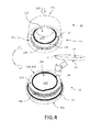
- Figure 4 shows a perspective view of an embodiment of the vessel 1 according to the invention, wherein vessel upper part 12 and lower vessel part 11 via corresponding threads 116, 126 are screwed together.
- the threads are holding means 13 of a first thread 116 on the side surface 115 of the elevation 114 and a correspondingly adapted mating thread 126 on the inner surface 125i of the side wall 125 of the recess 124 for mutual screwing with such a screw thread 116, 126 can
- Substrate 2 are held liquid-tight between the first and second bearing surfaces with a defined and reproducible contact pressure. Before the screwing, the substrate 2 is positioned on the first support surface 111 P2.
- the lower container part 11 comprises in the region below the substrate 2 a downwardly closed lower part volume 112, which is circulated by the first support surface 111 and which is bounded in the direction of the upper vessel part 12 by the substrate 2 positioned on the first support surface 111.
- chemically neutral liquids 4 may be filled for heating or cooling purposes to assist in the process of processing the side 21 of the substrate.
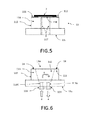
- Figure 5 shows an embodiment of the vessel base 11 with two holes 117 for venting the volume 118 below the substrate 2.
- the two holes 117 run from the upper side 11o of the vessel base 11 to the lower side 11 u of the vessel base 11. Since these holes 117 are only vent holes, no special requirements are placed on their shape and design.
- the person skilled in the art can produce the bores 117 in a suitable manner and produce a suitable number of bores 117. In another embodiment, even a single bore 117 may connect the upper side 11o to the lower side 11u of the vessel bottoms to deaerate the volume 118.
- FIG. 6 shows an embodiment of the vessel bottom 11 with a bottom volume 112 for filling and flushing with a liquid 4, which does not attack the substrate, for example, a chemically neutral liquid 4 such as water.
- the lower vessel part 11 here comprises an inlet opening 11 E and an outlet opening 11 A, so that the liquid 4 can flow through the lower part volume 112 during the processing of the substrate 2.
- the inlet opening 11 E and the outlet opening 11 A are hereby variably controllable by respectively adjustable valves 11 V.
- the process temperature of the substrate 2 can be kept very precisely at a target temperature during the processing of the side 21 become.
- Figure 7 shows an embodiment of the vessel top 12 with a first region 127 of a chemically resistant material, (a) in the lateral section and (b) in plan view from above.
- the first region 127 is made of a material which is at least sufficiently resistant to the surface-attacking liquid 3, while the vessel upper part 12 outside the first region 127 is at least partially made of a material which is not resistant to the surface-attacking liquid 3.
- the first region 127 extends on the side 12u facing the vessel lower part at least as far as the liquid-tight position of the vessel upper part 12 when the substrate 2 is inserted.
- the material costs for producing the vessel upper part 12 can be reduced by the possible partial use of less expensive materials.
- the first region 127 is reversibly supported in the vessel top 12 suitable for replacement with another first region 127.
- the first region 127 in this exemplary embodiment has an inwardly hollow cylindrical shape (shown in black in a lateral section), which is held in the cylindrical upper part 12 surrounding the first region 127 by means of press fit due to sufficient frictional forces.
- the person skilled in the art can also select other suitable shapes of the first region 127 adapted to the shape of the vessel upper part 12.
- the exchangeable first region 127 can always be used to select a first region 127 of a material (particularly resistant material) which is particularly suitable for the respective surface-engaging liquid used for the subsequent substrate processing.
- Figure 8 shows an embodiment of the vessel top with a pouring, (a) in the lateral section and (b) in plan view from above.
- the pouring means 128 serves for the reliable pouring out of the surface-attacking liquid 3 after one-sided processing of a substrate 1 from the top volume 122.
- the person skilled in the art can suitably choose the shape of the pouring means 128 in the context of the present invention, for example in the form of a spout or a pouring channel. As a result, manual handling of the vessel 1 can be facilitated and nevertheless made safe.
- Figure 9 shows an embodiment of a method according to the invention for one-sided processing BA of a substrate 2 with the vessel 1 according to the invention.
- the method comprises the steps of positioning P1 of the vessel base 11 on a base 5 in a position in which a first bearing surface 111 of the vessel base 11 of the Pad (5) facing away, the positioning P2 of the substrate 2 on the first support surface, the liquid-tight holding H of the substrate 2 between the first support surface 111 by applying a contact pressure A due to a suitable configuration of the first and second bearing surfaces (111, 121) and the shapes of the vessel bottom part (11) and the vessel top part (12), the filling B1 of a shell volume 122, arranged in the vessel top part 12, whose lower boundary is formed by the side of the substrate 2 to be processed, with a surface-engaging liquid 3, due to the previously reached fl sstechniksêtn holder H can not pass to the other side 22 of the substrate 2, via at least one filling opening 123 of the upper vessel portion 12 for processing BA of the substrate 2, where
- a lower part volume 112 located in the lower part of the vessel 11 in the region below the substrate 2 is filled B2, wherein the lower vessel part 11 is a Inlet opening 11 E in the lower part volume 112 and an outlet opening 11 A from the lower part volume 112, so that the liquid 4, the lower part volume 112 during the processing BA of the substrate 2 to flow through D.
- the processing BA of the substrate 2 is terminated after reaching the desired result by pouring AS the surface-engaging liquid 3 from the upper part volume 12 (E). Subsequently, the vessel 1 is opened O and the finished substrate 2 is removed from the vessel 1.
Landscapes
- Weting (AREA)
Abstract
Die Erfindung bezieht sich auf ein Gefäß (1) zur einseitigen Bearbeitung eines Substrats (2) und ein entsprechendes Verfahren. Dazu umfasst das Gefäß (1) ein Gefäßunterteil (11) und ein auf dem Gefäßunterteil (11) zur Halterung des Substrates (2) angeordneten Gefäßoberteil (12), wobei das Gefäßoberteil ein Oberteilvolumen (122) zur Aufnahme einer oberflächenangreifenden Flüssigkeit (3) zur Bearbeitung des Substrats umfasst, die über mindestens eine Einfüllöffnung (123) im Gefäßoberteil in das Oberteilvolumen (122) eingelassen werden kann (12), wobei das Gefäßunterteil (11) auf der dem Gefäßoberteil (12) zugewandten Seite (110) eine für das Substrat (2) geeignet angepasste erste Auflagefläche (111) umfasst und das Gefäßoberteil (12) auf der dem Gefäßunterteil (11) zugewandten Seite (12u) eine für das Substrat (2) geeignet angepasste zweite Auflagefläche (121) umfasst, wobei die ersten und zweiten Auflageflächen (111, 121) und die Formen des Gefäßunterteils (11) und des Gefäßoberteils (12) so ausgestaltet sind, dass das zwischen den ersten und zweiten Auflageflächen (111, 121) positionierte Substrat (2) flüssigkeitsdicht gehaltert (H) werden kann, so dass die oberflächenangreifenden Flüssigkeit (3) nicht von der zu bearbeitenden Seite (21) des Substrats (2) auf eine andere Seite (22) des Substrats (2) gelangen kann und das Oberteilvolumen eine ausreichende Größe besitzt, um eine für die Bearbeitung benötigte Menge der oberflächenangreifenden Flüssigkeit (3) aufzunehmen und während der Bearbeitung (BA) des Substrats (2) zu speichern (S), wobei eine untere Grenze des Oberteilvolumen (122) durch die zu bearbeitende Seite (21) des Substrats (2) gebildet wird. Mit dem erfindungsgemäßen Gefäß wird eine einseitige Bearbeitung eines Substrats mit einer verringerten Menge an oberflächenangreifender Flüssigkeit ermöglicht, wobei die Vorrichtung leicht und sicher zu handhaben ist und mit weniger Aufwand und zu geringeren Materialkosten gefertigt werden kann.The invention relates to a vessel (1) for one-sided processing of a substrate (2) and a corresponding method. For this purpose, the vessel (1) comprises a vessel bottom part (11) and a vessel top part (12) arranged on the vessel bottom part (11) for holding the substrate (2), the vessel top part comprising an upper part volume (122) for receiving a surface-attacking liquid (3) Machining of the substrate, which can be introduced into the upper part volume (122) via at least one filling opening (123) in the upper part of the vessel, wherein the lower part of the vessel (11) on the side (110) facing the upper part of the vessel (12) forms one for the substrate (2) suitably adapted first bearing surface (111) and the vessel upper part (12) on the vessel lower part (11) facing side (12u) for the substrate (2) suitably adapted second bearing surface (121), wherein the first and second Bearing surfaces (111, 121) and the shapes of the vessel bottom part (11) and of the vessel top part (12) are designed such that the between the first and second bearing surfaces (111, 121) positioned substrate (2) liquid-tight (H) can be held so that the surface-engaging liquid (3) can not pass from the side to be machined (21) of the substrate (2) on another side (22) of the substrate (2) and the shell volume is of sufficient size to receive and store an amount of surface-engaging liquid (3) needed for processing (S), during processing (BA) of the substrate (2), wherein a lower limit of the shell volume (122) to be machined side (21) of the substrate (2) is formed. With the vessel according to the invention, a one-sided processing of a substrate with a reduced amount of surface-engaging liquid is made possible, whereby the device is easy and safe to handle and can be manufactured with less effort and lower material costs.
Description
Die Erfindung betrifft ein Gefäß zur einseitigen Bearbeitung eines Substrats und ein entsprechendes Verfahren.The invention relates to a vessel for one-sided processing of a substrate and a corresponding method.
In der Mikrosystemtechnik wird nasschemisch geätzt oder gereinigt. Durch die Prozessfolge kann es manchmal notwendig sein, ein Substrat (beispielsweise einen sogenannten Wafer) nur einseitig nasschemisch zu bearbeiten. Dazu muss einerseits die Seite, die bearbeitet werden soll, mit der nasschemischen Flüssigkeit in Berührung gebracht werden und andererseits die Seite, die nicht bearbeitet werden soll, vor der nasschemischen Flüssigkeit geschützt werden. Dazu muss die nicht zu bearbeitende Seite eingekapselt werden.In microsystem technology, wet-chemical etching or cleaning takes place. Due to the process sequence, it may sometimes be necessary to process a substrate (for example, a so-called wafer) with wet-chemical only on one side. For this purpose, on the one hand, the side to be processed must be brought into contact with the wet-chemical liquid and, on the other hand, the side which is not to be processed must be protected from the wet-chemical liquid. To do this, the non-editable page must be encapsulated.
Es ist daher eine Aufgabe der Erfindung, eine Vorrichtung zur Verfügung zu stellen, mit der eine einseitige Bearbeitung eines Substrats mit einer verringerten Menge an oberflächenangreifender Flüssigkeit ermöglicht und wobei die Vorrichtung leicht und sicher zu handhaben ist und mit weniger Aufwand und zu geringeren Materialkosten gefertigt werden kann.It is therefore an object of the invention to provide an apparatus which allows one-sided processing of a substrate with a reduced amount of surface-attacking liquid and which device is easy and safe to handle and manufactured with less expense and lower material costs can.
Diese Aufgabe wird gelöst durch ein Gefäß zur einseitigen Bearbeitung eines Substrats mit einem Gefäßunterteil und einem auf dem Gefäßunterteil zur Halterung des Substrates angeordneten Gefäßoberteil, wobei das Gefäßoberteil ein Oberteilvolumen zur Aufnahme einer oberflächenangreifenden Flüssigkeit zur Bearbeitung des Substrats umfasst, die über mindestens eine Einfüllöffnung im Gefäßoberteil in das Oberteilvolumen eingelassen werden kann, wobei das Gefäßunterteil auf der dem Gefäßoberteil zugewandten Seite eine für das Substrat geeignet angepasste erste Auflagefläche umfasst und das Gefäßoberteil auf der dem Gefäßunterteil zugewandten Seite eine für das Substrat geeignet angepasste zweite Auflagefläche umfasst, wobei die ersten und zweiten Auflageflächen und die Formen des Gefäßunterteils und des Gefäßoberteils so ausgestaltet sind, dass das zwischen den ersten und zweiten Auflageflächen positionierte Substrat flüssigkeitsdicht gehaltert werden kann, so dass die oberflächenangreifende Flüssigkeit nicht von der zu bearbeitenden Seite des Substrats auf eine andere Seite des Substrats gelangen kann und das Oberteilvolumen eine ausreichende Größe besitzt, um eine für die Bearbeitung benötigte Menge der oberflächenangreifenden Flüssigkeit aufzunehmen und während der Bearbeitung des Substrats zu speichern, wobei eine untere Grenze des Oberteilvolumen durch die zu bearbeitende Seite des Substrats gebildet wird.This object is achieved by a vessel for one-sided processing of a substrate having a lower vessel part and a vessel upper part arranged on the vessel lower part for holding the substrate, wherein the vessel upper part comprises an upper part volume for receiving a surface-engaging liquid for processing the substrate, which has at least one filling opening in the vessel upper part in the Upper part volume can be inserted, wherein the lower part of the vessel on the upper side facing the vessel upper surface suitably adapted for the substrate comprises a first support surface and the vessel upper part on the side facing the vessel lower part suitable for the substrate adapted second support surface, wherein the first and second bearing surfaces and the Molds of the vessel bottom and the vessel top are designed so that the positioned between the first and second bearing surfaces substrate can be supported liquid-tight, so that the surface-engaging liquid can not get from the side to be processed of the substrate to another side of the substrate and the shell volume a has sufficient size to receive an amount of surface-engaging liquid needed for processing and to store it during processing of the substrate, wherein a lower limit of the shell volume is determined by d he to be machined side of the substrate is formed.
Der Begriff "Gefäß" bezeichnet dabei alle Körper, in die zumindest eine oberflächenangreifende Flüssigkeit eingefüllt und über einen Zeitraum gespeichert werden kann. Für die einseitige Bearbeitung eines Substrats wird die oberflächenangreifende Flüssigkeit nur von einer Seite des Gefäßes eingefüllt und nur in dem Bereich gespeichert, der lediglich Zugang zu einer Seite des Substrats besitzt.The term "vessel" refers to all bodies in which at least one surface-engaging liquid can be filled and stored over a period of time. For one-sided processing of a substrate, the surface-engaging liquid is filled only from one side of the vessel and stored only in the area which has access only to one side of the substrate.
Der Begriff "oberflächenangreifende Flüssigkeit" bezeichnet alle Flüssigkeiten, mit denen die Oberfläche eines Substrats bearbeitet werden kann, beispielsweise eine ätzende Flüssigkeit zur Bearbeitung eines SiliziumSubstrats (Silizium-Wafers). Die Begriffe "Bearbeitung" und "bearbeiten" bezeichnen nasschemische Vorgänge, die die bearbeitete Oberfläche des Substrats verändern, beispielsweise reinigen, aufrauen, chemisch modifizieren oder auf andere Weise verändern.The term "surface attacking liquid" refers to all liquids with which the surface of a substrate can be processed, for example a corrosive liquid for processing a silicon substrate (silicon wafer). The terms "processing" and "processing" refer to wet chemical processes that alter, for example, clean, roughen, chemically modify, or otherwise alter the machined surface of the substrate.
Der Begriff "Substrat" bezeichnet alle Körper, die für eine nasschemische Bearbeitung an deren Oberfläche mittels einer oberflächenangreifenden Flüssigkeit vorgesehen sind. Diese Körper müssen nicht zwangsläufig scheibenförmig ausgestaltet sein, wobei der Körper im Bereich der Auflageflächen allerdings so ausgestaltet sein muss, dass er mittels aufeinander drückender Auflageflächen flüssigkeitsdicht gehaltert werden kann. Hier können die Auflageflächen der Form des Körpers entsprechend angepasst sein. In einer Ausführungsform ist das Substrat scheibenförmig ausgestaltet. In diesem Fall sind die ersten und zweiten Auflageflächen zumindest im Wesentlichen parallel zueinander angeordnet. Sofern das erfindungsgemäße Gefäß ohne Dichtringe ausgestaltet ist, sind die Auflageflächen im Falle eines scheibenförmigen Substrats planparallel zueinander angeordnet. Das Substrat kann beliebige geometrische Formen besitzen. Beispielsweise kann ein scheibenförmiges Substrat zwar eine im Wesentlichen konstante Dicke besitzen, aber in seiner Fläche kreisförmig, rechteckig, quadratisch, hexagonal oder andersförmig gestaltet sein. Das Gefäß aus Gefäßoberteil und Gefäßunterteil, insbesondere die ersten und zweiten Auflageflächen sind so gestaltet, dass das für sie vorgesehene Substrat flüssigkeitsdicht gehaltert werden kann. Bei einem kreisrunden Substrat sind die ersten und zweiten Auflageflächen vorzugsweise ebenfalls kreisrund. Das gleiche gilt analog auch für die anderen möglichen Formen des Substrats (rechteckiges Substrat - rechteckig Auflageflächen, ...).The term "substrate" refers to all bodies that are provided for wet-chemical processing on their surface by means of a surface-engaging liquid. These bodies do not necessarily have to be disc-shaped, but the body in the region of the bearing surfaces must be designed in such a way that it can be held in a liquid-tight manner by means of pressing surfaces resting on one another. Here, the bearing surfaces of the shape of the body can be adjusted accordingly. In one embodiment, the substrate is disk-shaped. In this case, the first and second bearing surfaces are arranged at least substantially parallel to one another. If the vessel according to the invention is configured without sealing rings, the bearing surfaces are arranged plane-parallel to each other in the case of a disc-shaped substrate. The substrate may have any geometric shapes. For example, although a disk-shaped substrate may have a substantially constant thickness, it may be circular, rectangular, square, hexagonal, or other in shape. The vessel from the upper vessel part and lower vessel part, in particular the first and second bearing surfaces are designed so that the substrate provided for them can be held liquid-tight. In a circular substrate, the first and second bearing surfaces are preferably also circular. The same applies analogously to the other possible forms of the substrate (rectangular substrate - rectangular bearing surfaces, ...).
Das Gefäßoberteil ist dazu vorgesehen, die oberflächenangreifende Flüssigkeit zur Bearbeitung des Substrats in einem Oberteilvolumen aufzunehmen. Dazu kann das gesamte Gefäßoberteil aus einem Material bestehen, das chemisch resistent gegenüber der oberflächenangreifenden Flüssigkeit ist. In einer Ausführungsform umfasst das Gefäßoberteil einen das Oberteilvolumen begrenzenden ersten Bereich, der aus einem Material gefertigt ist, dass gegenüber der oberflächenangreifenden Flüssigkeit zumindest hinreichend resistent ist, während das Gefäßoberteil außerhalb des ersten Bereichs zumindest teilweise aus einem gegenüber der oberflächenangreifenden Flüssigkeit nicht resistenten Material gefertigt ist. Hierbei erstreckt sich der erste Bereich an der dem Gefäßunterteil zugewandten Seite zumindest bis zur flüssigkeitsabdichten Stelle des Gefäßoberteils bei eingelegtem Substrat. Geeignete oberflächenangreifende Flüssigkeiten zur Bearbeitung von Substraten sind beispielsweise
- a) Königswasser: 100 % HCL (Salzsäure)
und 100 % HNO3 (Salpetersäure), im Verhältnis 3:1; - b) Piranha , H2SO5 (Schwefelsäure) und H2O2 (Wasserstoffperoxid) im Verhältnis 1:1;
- c) RCA I: Wasser (H2O): H2O2: Ammoniumhydroxid (NH4OH) im Verhältniss 1:1:1 oder RCA II: H2O: H2O2: HCL im Verhältnissen 1:1:1; oder
- d) 100 % HNO3 und 40 % HF (Verhältnis 1:1).
- a) aqua regia: 100% HCL (hydrochloric acid)
and 100% HNO 3 (nitric acid), in the ratio 3: 1; - b) piranha, H 2 SO 5 (sulfuric acid) and H 2 O 2 (hydrogen peroxide) in the ratio 1: 1;
- c) RCA I: water (H 2 O): H 2 O 2 : ammonium hydroxide (NH 4 OH) in the ratio 1: 1: 1 or RCA II: H 2 O: H 2 O 2 : HCL in the proportions 1: 1: 1; or
- d) 100% HNO 3 and 40% HF (ratio 1: 1).
Geeignete resistente Materialien für das Gefäßoberteil, zumindest für den ersten Bereich sind beispielsweise Polyethylen (PE) und Polypropylen (PP), die gegen viele der verwendeten oberflächenangreifenden Flüssigkeiten hinreichend resistent sind. Auch der Einsatz von Keramiken oder Metall ist möglich. Als anderes Material kann beispielsweise Quarzglas für die oberflächenangreifenden Flüssigkeiten (b) und (c) gut verwendet werden. Als besonders resistentes Material kann PTFE für alle oben genannten oberflächenangreifenden Flüssigkeiten als Material für das Gefäßoberteil beziehungsweise für den ersten Bereich verwendet werden. Der Begriff "hinreichend resistent" bezeichnet dabei ein Material, das es ermöglicht, einige hundert Substrate mit oberflächenangreifenden Flüssigkeit zu bearbeiten, bevor die Oberfläche des Oberteilvolumens selbst chemisch so angegriffen wird, dass keine ausreichende Dichtwirkung gegenüber der oberflächenangreifenden Flüssigkeit mehr gegeben ist oder die Qualität der Bearbeitung des Substrats nicht mehr akzeptabel ist. Im Idealfall ist das Material des ersten Bereichs des Gefäßoberteils chemisch so resistent, dass es durch die oberflächenangreifende Flüssigkeit nicht angegriffen wird, beispielsweise aus Quarzglas (Ausnahme Flusssäure). Ein besonders resitentes Material gegenüber den verwendeten oberflächenangreifenden Flüssigkeiten ist PTFE (Polytetrafluorethylen, gelegentlich auch Polytetrafluorethen genannt). Sofern dieses Material nicht über 200° erhitzt wird, können mehr als tausend, gegebenenfalls mehrere tausend Substratbearbeitungen vorgenommen werden, ohne dass dieses Material durch die oberflächenangreifenden Flüssigkeiten zur Substatbearbeitung selber angegriffen wird. Durch diese Aufteilung des Gefäßoberteils in einen ersten Bereich und einen oder mehrere andere Bereiche muss nur ein Teil des Gefäßoberteils aus einem teuren chemisch resistenten Material, beispielsweise PTFE, Keramik, Glas oder Metall, gefertigt werden, während der restliche Bereich des Gefäßoberteils aus einem einfachen Material, beispielsweise Harnharzstoff als einfacher Kunststoff, bestehen kann, das beispielsweise eine weniger aufwendige Spritzgussfertigung ermöglicht.Suitable resistant materials for the vessel top, at least for the first region, are, for example, polyethylene (PE) and polypropylene (PP), which are sufficiently resistant to many of the surface-attacking fluids used. The use of ceramics or metal is possible. As another material, for example, quartz glass can be well used for the surface-engaging liquids (b) and (c). As a particularly resistant material, PTFE can be used as the material for the vessel top part or for the first area for all surface-attacking liquids mentioned above. The term "sufficiently resistant" refers to a material that makes it possible to process several hundred substrates with surface-engaging liquid before the surface of the shell volume itself is chemically attacked so that no more sufficient sealing effect against the surface-attacking liquid is given or the quality of Processing of the substrate is no longer acceptable. Ideally, the material of the first area of the Upper part of the vessel so chemically resistant that it is not attacked by the surface-attacking liquid, such as quartz glass (exception: hydrofluoric acid). A particularly resitent material to the surface-attacking fluids used is PTFE (polytetrafluoroethylene, sometimes called polytetrafluoroethene). If this material is not heated above 200 °, more than a thousand, possibly several thousand substrate treatments can be made without this material being attacked by the surface-engaging liquids themselves for substrate processing. As a result of this division of the vessel upper part into a first region and one or more other regions, only a part of the vessel upper part has to be manufactured from an expensive chemically resistant material, for example PTFE, ceramic, glass or metal, while the remaining region of the vessel upper part is made of a simple material , For example, urea resin as a simple plastic, may exist, for example, allows a less expensive injection molding production.
In einer Ausführungsform ist der erste Bereich reversibel im Gefäßoberteil geeignet zum Austausch gegen einen anderen ersten Bereich gehaltert. Dazu besitzt der erste Bereich eine geeignete Form, die eine reversible Halterung ermöglicht, beispielsweise eine symmetrische Form mit einem kreisförmigen Querschnitt (innen hohle Zylinderform) oder einem rechteckigen Querschnitt (innen hohle Quaderform) bei einem zylinderförmigen oder quaderförmigen Gefäßoberteil. Der Fachmann kann im Rahmen der vorliegenden Erfindung auch andere geeignete Formen des ersten Bereichs angepasst auf die Form des Gefäßoberteils wählen. Der erste Bereich kann beispielsweise durch einen Presssitz mittels ausreichender Reibungskräfte im restlichen Gefäßoberteil, das den ersten Bereich im Presssitz umgibt, gehaltert werden. Durch den austauschbaren ersten Bereich kann immer ein erster Bereich aus einem für die jeweilig angewendete oberflächenangreifende Flüssigkeit besonders geeigneten Material (besonders resistentes Material) für die nachfolgende Substratbearbeitung gewählt werden. Außerdem kann durch Austausch des ersten Bereichs vermieden werden, dass das komplette Gefäßoberteil bei einem abgenutzten ersten Bereich ausgetauscht werden müsste. Dadurch können Materialkosten vermieden und eine gute Prozessqualität bei der Substratbearbeitung gewährleistet werden.In one embodiment, the first region is reversibly supported in the vessel top suitable for replacement with another first region. For this purpose, the first region has a suitable shape that allows a reversible holder, for example, a symmetrical shape with a circular cross-section (inside hollow cylindrical shape) or a rectangular cross-section (inside hollow cuboid shape) in a cylindrical or cuboid vessel top. Within the scope of the present invention, the person skilled in the art can also select other suitable shapes of the first region adapted to the shape of the vessel upper part. The first region can be held, for example, by a press fit by means of sufficient frictional forces in the rest of the vessel upper part, which surrounds the first region in an interference fit. Due to the exchangeable first region, a first region of a material (particularly resistant material) which is particularly suitable for the respective surface-engaging liquid used can always be used for the following Substrate processing can be selected. In addition, it can be avoided by replacing the first area that the complete upper vessel part would have to be replaced at a worn first area. As a result, material costs can be avoided and good process quality can be ensured during substrate processing.
Das Gefäßunterteil dient dabei als Träger für das Substrat, wobei die erste Auflagefläche des Gefäßunterteils in Zusammenwirkung mit der zweiten Auflagefläche und dem Substrat eine Dichtwirkung gegenüber der oberflächenangreifenden Flüssigkeit herstellt, so dass keine oberflächenangreifende Flüssigkeit auf die andere Seite des Substrats gelangen kann. Die Dichtwirkung kann dabei im Rahmen der vorliegenden Erfindung durch verschiedene Dichtmechanismen erreicht werden. Beispielsweise kann als Dichtmechanismus ein Presssitz des Gefäßoberteils auf dem Gefäßunterteil verwendet werden, bei dem die ersten und zweiten Auflageflächen aufeinandergedrückt werden (Ausüben eines Anpressdrucks), so dass das Substrat flüssigkeitsdicht umschlossen wird und das Gefäßoberteil aufgrund des Presssitzes für den Bearbeitungsvorgang in seiner Position verbleibt. Dazu müssen die Formen von Gefäßoberteil und Gefäßunterteil so aufeinander angepasst sein, dass das Gefäßoberteil mit Druck auf das Gefäßunterteil aufgeschoben werden kann. In einer alternativen Ausführungsform kann das Gefäßoberteil auch auf das Gefäßunterteil aufgeschraubt werden. Es können von Fachmann auch andere Dichtmechanismen zum Ausüben eines Anpressdrucks auf die ersten und zweiten Auflageflächen im Rahmen der vorliegenden Erfindung gewählt werden. Damit kann das Gefäß zur Bearbeitung eines Substrats schnell und mit geringem Aufwand in Betrieb genommen werden. Als andere Seite wird hier der Bereich bezeichnet, der von der oberflächenangreifenden Flüssigkeit nicht bearbeitet werden soll. Es ist daher je nach gewähltem Dichtmechanismus nicht prinzipiell ausgeschlossen, dass die oberflächenangreifende Flüssigkeit den Rand des Substrats oder die andere Seite des Substrats im Randbereich erreicht. Der Dichtmechanismus muss lediglich verhindern, dass die oberflächenangreifende Flüssigkeit die Bereiche der anderen Seite des Substrats erreicht, die nicht von der oberflächenangreifenden Flüssigkeit bearbeitet werden sollen. Nur diese Bereiche werden in der vorliegenden Erfindung als andere Seite bezeichnet. Insofern kommt das Gefäßunterteil nicht oder nur im sehr geringen Maße mit der oberflächenangreifenden Flüssigkeit in Berührung. In einer Ausführungsform umfasst dazu zumindest die erste Auflagefläche einen Dichtring. In einer anderen Ausführungsform ist der Dichtmechanismus zwischen erster und zweiter Auflagefläche so ausgestaltet, dass das Gefäßunterteil nicht mit der oberflächenangreifenden Flüssigkeit in Berührung kommt. In diesem Fall muss das Gefäßunterteil nicht aus einem Material bestehen, das chemisch resistent gegenüber der oberflächenangreifenden Flüssigkeit ist. Dadurch kann das Gefäßunterteil aus einem kostengünstigeren Material, beispielsweise einem einfachen Kunststoff wie Harnstoffharz, hergestellt sein. Dazu umfasst zumindest die erste Auflagefläche einen Dichtring oder die erste Auflagefläche und die zweite Auflagefläche umfassen beide einen Dichtring. In anderen Ausführungsformen können auch mehrere Dichtringe pro Auflagefläche verwendet werden. Vorzugsweise sind im Falle von Dichtringen in erster und zweiter Auflagefläche diese Dichtringe in Druckrichtung gesehen übereinander angeordnet, um Spannungen im Substrat während der Bearbeitung zu vermeiden und/oder die Dichtwirkung des Dichtrings in/auf der zweiten Auflagefläche noch weiter zu verstärken. Der Dichtring kann dabei jede geeignete Form besitzen, beispielsweise kann der Dichtring einen zylinderförmigen oder rechteckigen Querschnitt besitzen. Die umlaufende Form des Dichtrings ist dabei auf den zu bearbeitenden Bereich auf der einen Seite des Substrats angepasst. Je nach Form des abzuschirmenden Bereichs oder des zu bearbeitenden Bereichs des Substrats kann der Dichtring eine Kreisform, eine rechteckige oder quadratische Form oder eine andere Form besitzen.The lower vessel part serves as a carrier for the substrate, wherein the first bearing surface of the vessel base in cooperation with the second bearing surface and the substrate produces a sealing action against the surface-engaging liquid, so that no surface-attacking liquid can reach the other side of the substrate. The sealing effect can be achieved in the context of the present invention by various sealing mechanisms. For example, as a sealing mechanism, a press fit of the vessel top can be used on the vessel bottom, in which the first and second bearing surfaces are pressed together (exerting a contact pressure), so that the substrate is liquid-tightly enclosed and the vessel upper part remains in its position due to the press fit for the machining operation. For this purpose, the shapes of the upper vessel part and the lower vessel part must be adapted to each other so that the upper vessel part can be pushed with pressure on the lower vessel part. In an alternative embodiment, the upper vessel part can also be screwed onto the vessel lower part. Other seal mechanisms for exerting a contact pressure on the first and second contact surfaces within the scope of the present invention may be selected by a person skilled in the art. Thus, the vessel for processing a substrate can be put into operation quickly and with little effort. The other side here is the area which should not be processed by the surface-attacking liquid. It is therefore not excluded in principle, depending on the selected sealing mechanism, that the surface-engaging liquid the edge of the substrate or the other side of the substrate in the edge region reached. The sealing mechanism must only prevent the surface-engaging liquid from reaching the areas of the other side of the substrate that are not to be processed by the surface-engaging liquid. Only these regions are referred to as the other side in the present invention. In this respect, the lower part of the vessel is not or only to a very small extent with the surface-engaging liquid in contact. In one embodiment, at least the first bearing surface comprises a sealing ring for this purpose. In another embodiment, the sealing mechanism between the first and second support surface is designed such that the vessel lower part does not come into contact with the surface-engaging liquid. In this case, the vessel bottom does not have to be made of a material which is chemically resistant to the surface attacking liquid. As a result, the vessel lower part may be made of a less expensive material, for example a simple plastic such as urea resin. For this purpose, at least the first bearing surface comprises a sealing ring or the first bearing surface and the second bearing surface both comprise a sealing ring. In other embodiments, a plurality of sealing rings per support surface may be used. Preferably, in the case of sealing rings in the first and second support surface, these sealing rings are arranged one above the other in the printing direction in order to avoid stresses in the substrate during processing and / or to further enhance the sealing effect of the sealing ring in / on the second support surface. The sealing ring may have any suitable shape, for example, the sealing ring may have a cylindrical or rectangular cross-section. The circumferential shape of the sealing ring is adapted to the area to be machined on one side of the substrate. Depending on the shape of the region to be shielded or the area of the substrate to be processed, the sealing ring may have a circular shape, a rectangular or square shape or another shape.
Außerdem muss das Oberteilvolumen eine ausreichende Größe besitzen, um eine für die Bearbeitung benötigte Menge der oberflächenangreifenden Flüssigkeit aufzunehmen zu können. Bei einem Oberteilvolumen, dessen Grundfläche durch die zu bearbeitende Fläche des Substrats gegeben ist, sollte die Höhe des Volumens nicht weniger als 25mm, vorzugsweise 35mm oder in Abhängigkeit von der jeweiligen Bearbeitungsart und Bearbeitungsziel mehr betragen. Da die Höhe des Volumens der Höhe des Gefäßoberteils oberhalb der zweiten Auflagefläche entspricht, sollte somit das Gefäßoberteil eine Höhe von nicht weniger als 25mm, vorzugsweise 35mm oder mehr, besitzen. Die damit festgelegte Größe des Oberteilvolumens ist deutlich geringer, als das Volumen eines Ätzbades gemäß dem Stand der Technik, das mit entsprechender oberflächenangreifender Flüssigkeit vollständig gefüllt wird, um darin die Einkapselungen gemäß dem Stand der Technik hineinlegen zu können. Mit dem erfindungsgemäßen Gefäß und dem lediglich mit der für den Bearbeitungsprozess notwendigen Menge der oberflächenangreifenden Flüssigkeit zu befüllenden Oberteilvolumens, können bei gleichem Prozessergebnis gegenüber dem Stand der Technik bis zu 90% an oberflächenangreifender Flüssigkeit eingespart werden. Diese Einsparung ist insbesondere wichtig bei Bearbeitungsprozessen, bei denen aus Reinheitsgründen die oberflächenangreifende Flüssigkeit nur für die Bearbeitung eines einzigen Substrats benutzt werden kann. Dadurch wird der Verbrauch an oberflächenangreifender Flüssigkeit gegenüber dem Stand der Technik stark verringert.In addition, the shell volume must be of sufficient size to to be able to take up a quantity of surface-attacking liquid required for processing. In a shell volume whose base area is given by the surface of the substrate to be processed, the height of the volume should be not less than 25mm, preferably 35mm or more, depending on the particular machining and machining target. Since the height of the volume corresponds to the height of the vessel upper part above the second bearing surface, the vessel upper part should therefore have a height of not less than 25 mm, preferably 35 mm or more. The size of the shell volume determined therewith is significantly less than the volume of a prior art etching bath that is completely filled with appropriate surface-engaging liquid to allow the encapsulation of the prior art to be incorporated therein. With the vessel according to the invention and the shell volume to be filled only with the amount of surface-attacking liquid necessary for the machining process, up to 90% of surface-attacking liquid can be saved with the same process result compared to the prior art. This saving is particularly important in machining processes where, for reasons of purity, the surface-engaging liquid can only be used to process a single substrate. As a result, the consumption of surface-engaging liquid is greatly reduced compared to the prior art.
Die Formen des Gefäßunterteils und des Gefäßoberteils können sich je nach Anwendungsbereich deutlich unterscheiden. Die Form muss allerdings so ausgestaltet sein, dass das zwischen den ersten und zweiten Auflageflächen positionierte Substrat flüssigkeitsdicht gehaltert werden kann. Der Fachmann kann im Rahmen der vorliegenden Erfindung die für das jeweilige zu bearbeitenden Substrat geeignete Form für das Gefäßunterteil und das Gefäßoberteil wählen.The shapes of the lower container part and the upper part of the container may differ significantly depending on the field of application. However, the shape must be designed such that the substrate positioned between the first and second bearing surfaces can be held in a liquid-tight manner. Within the scope of the present invention, the person skilled in the art can select the shape suitable for the respective substrate to be processed for the vessel bottom part and the vessel top part.
In einer Ausführungsform umfasst das Gefäß ein oder mehrere Haltemittel zum Ausüben eines Anpressdrucks zumindest der ersten und zweiten Auflagenflächen auf das zwischen ihnen gehalterte Substrat. Diese Haltemittel können gegebenenfalls einen durch die Form und das Gewicht der Gefäßober-und Gefäßunterteile bereits gegebenen Anpressdruck noch weiter verstärken, um die flüssigkeitsdichte Halterung weiter zu verbessern, beispielsweise um einen Ausdehneffekt für das Gefäßoberteil, dass beispielsweise im Presssitz auf dem Gefäßunterteil sitzt, durch heiße oberflächenangreifende Flüssigkeiten oder entstehende Prozesswärme zu kompensieren. In einer bevorzugten Ausführungsform umfasst das Haltemittel ein oder mehreren Elemente aus der Gruppe Klemmen, Federn, Schraubvorrichtungen oder Spannvorrichtungen.In one embodiment, the vessel comprises one or more holding means for exerting a contact pressure of at least the first and second support surfaces on the substrate held between them. If desired, these retaining means can further reinforce a contact pressure already given by the shape and weight of the upper and lower vessel parts in order to further improve the liquid-tight support, for example by an expansion effect for the upper part of the vessel, which is seated for example in an interference fit on the lower part of the vessel compensate for surface-attacking liquids or developing process heat. In a preferred embodiment, the holding means comprises one or more elements from the group of clamps, springs, screwing devices or clamping devices.
In einer weiteren Ausführungsform umfasst das Gefäßunterteil eine umlaufende Erhöhung mit einer Seitenfläche, deren oberer Rand die erste Auflagefläche darstellt, und das Gefäßoberteil eine umlaufende Vertiefung mit einer Seitenwand und einem tieferliegenden Rand, wobei der tieferliegende Rand die zweite Auflagefläche darstellt, wobei die Vertiefung so ausgeformt ist, dass die Seitenwand der Vertiefung übergreifend über die Erhöhung des Gefäßunterteils zur flüssigkeitsdichten Halterung des Substrats zwischen den ersten und zweiten Auflageflächen angeordnet werden kann. Durch diese Ausführungsform kann das Gefäßoberteil ortsfest zum Gefäßunterteil positioniert werden, da die Seitenwand des Gefäßoberteils an der Seitenfläche des Gefäßunterteils anliegt. Damit können sich die ersten und zweiten Auflageflächen nicht gegeneinander verschieben. Sind die Formen der Erhöhung und der Vertiefung so aufeinander angepasst, dass das Gefäßoberteil unter Ausübung eine Kraft auf das Gefäßunterteil geschoben werden muss, so kann der Anpressdruck des oberen Rands der Erhöhung des Gefäßunterteils auf den tieferliegenden umlaufenden Rand des Gefäßoberteils als erste und zweite Auflageflächen durch den resultierenden Presssitz vom Gefäßoberteil auf dem Gefäßunterteil ausgeübt werden. Dieser Presssitz kann dadurch verstärkt werden, dass die sich berührenden Teile von Gefäßoberteil und Gefäßunterteil, zumindest die Seitenwände der Erhöhung und der Vertiefung, aus einem weichen Material, beispielsweise Kunststoff, gefertigt sind und somit über Reibungseffekte besonders fest aufeinander sitzen.In a further embodiment, the vessel lower part comprises a circumferential elevation with a side surface, the upper edge of which represents the first bearing surface, and the vessel upper part has a circumferential recess with a side wall and a lower edge, wherein the lower edge represents the second bearing surface, wherein the recess is formed is that the side wall of the recess can be arranged across the increase of the vessel bottom for liquid-tight mounting of the substrate between the first and second bearing surfaces. By means of this embodiment, the vessel upper part can be stationarily positioned relative to the vessel lower part, since the side wall of the vessel upper part bears against the side surface of the vessel lower part. Thus, the first and second bearing surfaces can not move against each other. If the shapes of the elevation and the depression are adapted to one another such that a force has to be pushed onto the vessel lower part while exerting force, then the contact pressure of the upper edge of the elevation of the vessel lower part can be applied to the lower peripheral edge of the vessel upper part as first and second bearing surfaces the resulting interference fit be exerted by the upper vessel part on the lower vessel part. This interference fit can be enhanced by the fact that the touching parts of vessel upper part and vessel lower part, at least the side walls of the elevation and the recess, are made of a soft material, such as plastic, and thus sit particularly firmly on each other via friction effects.
In einer bevorzugten Ausführungsform besteht das Haltemittel aus einem ersten Gewinde auf der Seitenfläche der Erhöhung und aus einem entsprechend darauf angepassten Gegengewinde auf der inneren Fläche der Seitenwand der Vertiefung zur gegenseitigen Verschraubung. Über die Verschraubung kann ein definierter Anpressdruck der ersten und zweiten Auflageflächen aufeinander und gemeinsam auf das Substrat reproduzierbar eingestellt werden. Auf diese Weise lässt sich eine zuverlässige flüssigkeitsdichte Halterung des Substrats zwischen der ersten und zweiten Auflagefläche herstellen.In a preferred embodiment, the retaining means consists of a first thread on the side surface of the elevation and of a correspondingly adapted mating thread on the inner surface of the side wall of the recess for mutual screwing. About the screw a defined contact pressure of the first and second bearing surfaces can be adjusted to each other and reproducible together on the substrate. In this way, a reliable liquid-tight mounting of the substrate between the first and second bearing surface can be produced.
In einer weiteren Ausführungsform umfasst das Gefäßunterteil innerhalb der von der ersten Auflagefläche umlaufenden Fläche mindestens eine von der oberen Seite zur unteren Seite des Gefäßunterteils durchlaufende Bohrung. Da zwischen dem gehalterten Substrat und dem Gefäßunterteil immer ein gewisses (eventuell kleines) Luftvolumen eingeschlossen wird, kann sich dieses gegebenenfalls während des Bearbeitungsprozesses aufgrund der dabei möglicherweise freiwerdenden Wärme oder durch eine bereits erwärmte oberflächenangreifende Flüssigkeit erhitzen und so einen Druck auf das Substrat ausüben. Je nach Wärmeentwicklung und Größe des Luftvolumens können sich Spannungen im Substrat bilden, die gegebenenfalls das Substrat beschädigen könnten. Die Bohrung sorgt dafür, dass die sich ausdehnende Luft aus dem Volumen unterhalb des Substrats entweichen kann. Da zumindest die Unterseite des Gefäßunterteils nicht in Berührung mit der oberflächenangreifenden Flüssigkeit kommt, sind an die Bohrung keine besonderen Anforderungen gestellt. Das Gefäßunterteil wird typischerweise auf eine ebenen Unterlage gestellt, so dass die Luft einfach aus der Bohrung entlang der Unterlage entweichen kann.In a further embodiment, the vessel lower part comprises at least one bore extending from the upper side to the lower side of the vessel lower part within the surface running around from the first bearing surface. Since a certain (possibly small) volume of air is always trapped between the supported substrate and the lower vessel part, it may possibly heat up during the processing process due to the possibly released heat or through an already heated surface-attacking liquid and thus exert a pressure on the substrate. Depending on the evolution of heat and the size of the air volume, stresses can form in the substrate which could possibly damage the substrate. The bore ensures that the expanding air can escape from the volume below the substrate. Since at least the bottom of the container base does not come into contact with the surface-engaging liquid, no special requirements are placed on the bore. The vessel bottom is typically placed on a flat surface so that the air can easily escape from the bore along the base.
In einer weiteren Ausführungsform umfasst das Gefäßunterteil zumindest in dem Bereich unterhalb des Substrates ein verschließbares Unterteilvolumen für Flüssigkeiten, das von der ersten Auflagefläche umlaufen wird und das in Richtung des Gefäßoberteils durch das auf der ersten Auflagefläche positionierte Substrat begrenzt wird. Die in das Unterteilvolumen einzufüllenden Flüssigkeiten sind keine oberflächenangreifenden Flüssigkeiten, da die zum Gefäßunterteil zeigende Seite des Substrats ("andere Seite") nicht bearbeitet werden soll (einseitige Bearbeitung des Substrats). Die in das Unterteilvolumen eingelassene Flüssigkeit kann beispielsweise das Substrat rückseitig erhitzen oder abkühlen, so dass auch längere einseitig temperierte Ätzprozesse durchgeführt werden können.In a further embodiment, the vessel bottom part comprises at least in the region below the substrate a closable lower part volume for liquids, which is circulated by the first contact surface and which is delimited in the direction of the vessel upper part by the substrate positioned on the first contact surface. The liquids to be filled in the lower part volume are not surface-engaging liquids since the side of the substrate ("other side") facing the lower part of the vessel is not to be processed (one-sided processing of the substrate). The liquid introduced into the lower part volume can, for example, heat or cool the substrate on the back, so that longer one-sidedly tempered etching processes can also be carried out.
In einer bevorzugten Ausführungsform umfasst das Gefäßunterteil zumindest eine Einlassöffnung und eine Auslassöffnung, so dass die Flüssigkeiten durch das Unterteilvolumen zumindest während der Bearbeitung des Substrates durchfließen können, vorzugsweise sind die Einlassöffnung und/oder die Auslassöffnung durch mindestens ein einstellbares Ventil variabel steuerbar. Dadurch können Flüssigkeiten zu Kühl- oder Heizzwecken sehr präzise durch das Unterteilvolumen durchgeleitet werden, so dass eine bestimmte Substrattemperatur über einen langen Zeitraum sehr genau konstant gehalten werden kann. Dies ist gerade für die Steuerung der Ätzprozesse, die temperatursensitiv verlaufen, sehr wichtig.In a preferred embodiment, the lower vessel part comprises at least one inlet opening and one outlet opening, so that the liquids can flow through the lower part volume at least during the processing of the substrate, preferably, the inlet opening and / or the outlet opening are variably controllable by at least one adjustable valve. As a result, liquids for cooling or heating purposes can be passed very precisely through the lower part volume, so that a certain substrate temperature can be kept very precisely constant over a long period of time. This is very important for the control of etching processes, which are temperature-sensitive.
In einer weiteren Ausführungsform umfasst das Gefäßoberteil ein Ausgießmittel, beispielsweise einen kannenähnlichen Ausguss wie eine Tülle, zum sicheren Ausgießen der oberflächenangreifenden Flüssigkeit, nach erfolgter einseitiger Bearbeitung eines Substrats, aus dem Oberteilvolumen. Dadurch wird eine Bediensicherheit gegenüber unbeabsichtigtem Verschütten der oberflächenangreifenden Flüssigkeit erreicht.In a further embodiment, the vessel upper part comprises a pouring means, for example a can-like spout such as a spout, for the secure pouring out of the surface-engaging liquid, after unilateral processing of a substrate, from the top volume. As a result, an operating safety against unintentional spilling of the surface-engaging liquid is achieved.
Die Erfindung betrifft des Weiteren ein Verfahren zur einseitigen Bearbeitung eines Substrats mit mindestens einer oberflächenangreifenden Flüssigkeit unter Verwendung eines Gefäßes, umfassend ein Gefäßunterteil und ein Gefäßoberteil gemäß der vorliegenden Erfindung, umfassend die Schritte:
- Positionieren des Gefäßunterteils auf einer Unterlage in einer Position, in der eine erste Auflagefläche des Gefäßunterteils von der Unterlage abgewandt ist;
- Positionieren des Substrats auf der ersten Auflagefläche;
- Flüssigkeitsdichtes Haltern des Substrats zwischen der ersten Auflagefläche und einer zweiten Auflagefläche des Gefäßoberteils, die an der Seite des Gefäßoberteils angeordnet ist, die der ersten Auflagefläche zugewandt ist, durch Bilden des Gefäßes aus dem Gefäßunterteil und dem Gefäßoberteil mittels einer geeigneten Ausgestaltung der ersten und zweiten Auflageflächen und der Formen des Gefäßunterteils und des Gefäßoberteils;
- Befüllen eines Oberteilvolumens angeordnet im Gefäßoberteil, dessen untere Begrenzung durch die zu bearbeitende Seite des Substrats gebildet wird, mit einer oberflächenangreifenden Flüssigkeit, die aufgrund der flüssigkeitsdichten Halterung nicht auf die andere Seite des Substrate gelangen kann, über zumindest eine Einfüllöffnung des Gefäßoberteils zur Bearbeitung des Substrats;
- Speichern der oberflächenangreifenden Flüssigkeit in dem Oberteilvolumen während der Bearbeitung des Substrats.
- Positioning the vessel base on a base in a position in which a first bearing surface of the vessel base is remote from the base;
- Positioning the substrate on the first support surface;
- Liquid-tight holding of the substrate between the first bearing surface and a second bearing surface of the vessel upper part, which is arranged on the side of the vessel upper part, which faces the first bearing surface, by forming the vessel from the vessel bottom and the vessel upper part by means of a suitable configuration of the first and second bearing surfaces and the shapes of the vessel bottom and the vessel top;
- Filling of a shell volume arranged in the vessel upper part, whose lower boundary is formed by the side of the substrate to be processed, with a surface-engaging liquid, which can not reach the other side of the substrate due to the liquid-tight holder, via at least one filling opening of the vessel top for processing the substrate ;
- Storing the surface-engaging liquid in the shell volume during processing of the substrate.
Diese Einfüllöffnung im Gefäßoberteil kann vom Fachmann im Rahmen der vorliegenden Erfindung geeignet ausgestaltet werden. Beispielsweise ist das Gefäßoberteil innen hohl ausgeführt, so dass die Einfüllöffnung der gesamte Bereich der Oberseite des Gefäßoberteils innerhalb eines umlaufenden Rands ist.This filling opening in the vessel upper part can be designed by the skilled person in the context of the present invention suitable. By way of example, the vessel upper part is hollow on the inside so that the filling opening is the entire area of the upper side of the vessel upper part within a peripheral edge.
In einer Ausführungsform umfasst das Verfahren den weiteren Schritt des Befüllens eines im Gefäßunterteil in dem Bereich unterhalb des Substrates befindlichen Unterteilvolumens, das von der ersten Auflagefläche umlaufen wird und das in Richtung des Gefäßoberteils durch das auf der ersten Auflagefläche positionierte Substrat begrenzt wird, zumindest während des Bearbeitens des Substrats mit einer Flüssigkeit (andere oder zweite Flüssigkeit), die keine oberflächenangreifende Flüssigkeit istIn one embodiment, the method comprises the further step of filling a lower volume in the lower part of the vessel in the region below the substrate, which is circumscribed by the first supporting surface and which is delimited towards the vessel upper part by the substrate positioned on the first supporting surface, at least during the Working the substrate with a liquid (other or second liquid) that is not a surface-attacking liquid
In einer Ausführungsform umfasst das Verfahren den weiteren Schritt des Durchspülens des Unterteilvolumens mit der Flüssigkeit, wozu der Gefäßunterteil eine Einlassöffnung in das Unterteilvolumen und eine Auslassöffnung aus dem Unterteilvolumen umfasst.In one embodiment, the method comprises the further step of purging the sub-volume with the liquid, to which the vessel base comprises an inlet opening in the lower part volume and an outlet opening from the lower part volume.
In einer weiteren Ausführungsform des Verfahrens wird die Bearbeitung des Substrats durch Ausgießen der oberflächenangreifenden Flüssigkeit aus dem Oberteilvolumen beendet. Da sich die oberflächenangreifende Flüssigkeit lediglich im Oberteilvolumen befindet, nicht aber mit der äußeren Oberfläche von Gefäßoberteil und Gefäßunterteil in Berührung kommt, kann das Ausgießen auch manuell ohne weitere Schutzmaßnahmen erfolgen, was die Handhabung des Bearbeitungsprozesses stark vereinfacht.In a further embodiment of the method, the processing of the substrate is terminated by pouring the surface-engaging liquid from the top volume. Since the surface-attacking liquid is only in the upper part volume, but does not come into contact with the outer surface of the vessel upper part and vessel lower part, the pouring can also be done manually without further protective measures, which greatly simplifies the handling of the processing process.
Diese und andere Aspekte der Erfindung werden im Detail in den Abbildungen wie folgt gezeigt:
- Fig.1:
- eine Ausführungsform des erfindungsgemäßen Gefäßes im seitlichen Schnitt mit (a) getrennten Gefäßoberteil und Gefäßunterteil und (b) das gebildete Gefäß mit flüssigkeitsdicht gehalterten Substrat;
- Fig.2:
- Ausführungsformen des erfindungsgemäßen Gefäßes mit Haltemitteln in Form (a) einer Klammervorrichtung und (b) eines Schnappverschlusses;
- Fig.3:
- verschiedene Ausführungsformen des Gefäßes in Draufsicht von oben mit (a) quadratischem Querschnitt, (b) kreisrundem Querschnitt, (c) rechteckigem Querschnitt und (d) hexagonalem Querschnitt;
- Fig.4:
- eine perspektivische Ansicht einer Ausführungsform des erfindungsgemäßen Gefäßes, wobei Gefäßoberteil und Gefäßunterteil über entsprechende Gewinde miteinander verschraubbar sind;
- Fig.5:
- eine Ausführungsform des Gefäßunterteils mit Bohrungen zur Entlüftung des Volumens unterhalb des Substrats;
- Fig.6:
- eine Ausführungsform des Gefäßunterteils mit einem Unterteilvolumen zum Befüllung und Durchspülen mit einer Flüssigkeit, die das Substrat nicht angreift;
- Fig.7:
- eine Ausführungsform des Gefäßoberteils mit einem ersten Bereich aus einem chemisch resistenten Material, (a) im seitlichen Schnitt und (b) in Draufsicht von oben;
- Fig.8:
- eine Ausführungsform des Gefäßoberteils mit einem Ausgießmittel, (a) im seitlichen Schnitt und (b) in Draufsicht von oben;
- Fig.9:
- eine Ausführungsform eines erfindungsgemäßen Verfahrens zur einseitigen Bearbeitung eines Substrats mit dem erfindungsgemäßen Gefäß.
- Fig.1:
- an embodiment of the vessel according to the invention in the lateral section with (a) separate upper vessel part and vessel bottom part and (b) the vessel formed with a liquid-tight supported substrate;
- Figure 2:
- Embodiments of the container according to the invention with holding means in the form of (a) a stapling device and (b) a snap closure;
- Figure 3:
- various embodiments of the vessel in plan view from above with (a) square cross section, (b) circular cross section, (c) rectangular cross section and (d) hexagonal cross section;
- Figure 4:
- a perspective view of an embodiment of the vessel according to the invention, wherein vessel upper part and lower vessel part are screwed together via corresponding threads;
- Figure 5:
- an embodiment of the vessel bottom with holes for venting the volume below the substrate;
- Figure 6:
- an embodiment of the vessel bottom with a bottom volume for filling and flushing with a liquid that does not attack the substrate;
- Figure 7:
- an embodiment of the vessel upper part with a first region of a chemically resistant material, (a) in the lateral section and (b) in plan view from above;
- Figure 8:
- an embodiment of the vessel upper part with a pouring, (a) in the lateral section and (b) in plan view from above;
- Figure 9:
- an embodiment of a method according to the invention for one-sided processing of a substrate with the vessel according to the invention.
Die hier gezeigten Ausführungsformen stellen nur Beispiele für die vorliegende Erfindung dar und dürfen daher nicht einschränkend verstanden werden. Alternative durch den Fachmann in Erwägung gezogene Ausführungsformen sind gleichermaßen vom Schutzbereich der vorliegenden Erfindung umfasst.The embodiments shown herein are only examples of the present invention and therefore should not be considered as limiting. Alternative embodiments contemplated by one skilled in the art are equally within the scope of the present invention.
- 11
- Gefäßvessel
- 1111
- GefäßunterteilVessel bottom
- 11o11o
- die dem Gefäßoberteil zugewandte Seite des Gefäßunterteilsthe vessel upper part facing side of the vessel base
- 11u11u
- untere Seite des Gefäßunterteils (gegenüber der oberen Seite)lower side of the lower part of the container (opposite the upper side)
- 111111
- erste Auflageflächefirst contact surface
- 112112
- (verschließbares) Unterteilvolumen(closable) base volume
- 113E113E
- Einlassöffnunginlet port
- 113A113A
- Auslassöffnungoutlet
- 11V11V
- Ventile für Einlass- und/oder AuslassöffnungValves for inlet and / or outlet
- 114114
- umlaufende Erhöhungcircumferential increase
- 115115
- Seitenwand der umlaufenden ErhöhungSidewall of the circumferential elevation
- 116116
- erstes Gewinde auf der Seitenfläche der Erhöhungfirst thread on the side surface of the elevation
- 117117
- durchlaufende Bohrungcontinuous bore
- 118118
- Volumen unterhalb des SubstratsVolume below the substrate
- 1212
- GefäßoberteilVessel shell
- 12u12u
- die dem Gefäßunterteil zugewandte Seite des Gefäßoberteilsthe lower part of the vessel facing side of the vessel upper part
- 12o12o
- obere Seite des Gefäßoberteils (gegenüber 12u)upper side of the vessel upper part (opposite 12u)
- 121121
- zweite Auflageflächesecond bearing surface
- 122122
- OberteilvolumenShell volume
- 123123
- Einfüllöffnung für OberteilvolumenFilling opening for shell volume
- 124124
- umlaufende Vertiefungcircumferential recess
- 125125
- Seitenwand der umlaufenden VertiefungSidewall of the circumferential recess
- 125i125i
- innere Fläche der Seitenwand der Vertiefunginner surface of the side wall of the recess
- 126126
- Gegengewinde auf der Seitenwand der umlaufenden VertiefungCounter thread on the side wall of the circumferential recess
- 127127
- erster Bereich des Gefäßoberteils (Innenseite zum Oberteilvolumen)first area of the upper part of the vessel (inside to the upper part volume)
- 128128
- Ausgießmittelspout
- 1313
- Haltemittelholding means
- 1414
- Dichtringseal
- 22
- Substratsubstratum
- 2121
- eine Seite des Substrats (obere Seite)one side of the substrate (upper side)
- 2222
- die andere Seite des Substrats (untere Seite)the other side of the substrate (lower side)
- 33
- oberflächenangreifende Flüssigkeitsurface attacking liquid
- 44
- andere Flüssigkeitenother liquids
- 55
- Unterlagedocument
- AA
- Ausübens eines AnpressdrucksApplying a contact pressure
- ABFROM
-
Ablassen der anderen Flüssigkeit 4 aus dem UnterteilvolumenDraining the
other liquid 4 from the bottom part volume - ASAS
- Ausgießen der oberflächenangreifenden Flüssigkeit aus dem OberteilvolumenPouring the surface-engaging liquid from the shell volume
- B1B1
- Befüllen eines Oberteilvolumens mit einer oberflächenangreifenden FlüssigkeitFilling a shell volume with a surface attacking liquid
- B2B2
- Befüllen des UnterteilvolumensFilling the lower part volume
- BABA
- Bearbeiten des SubstratsEditing the substrate
- DD
-
Durchspülens des Unterteilvolumens mit der anderen Flüssigkeit 4Purging the lower part volume with the
other liquid 4 - Ee
- Beenden der Bearbeitung des SubstratsStop the processing of the substrate
- HH
- Flüssigkeitsdichtes Haltern des Substrats zwischen der ersten Auflagefläche und einer zweiten AuflageflächeLiquid-tight holding of the substrate between the first support surface and a second support surface
- OO
- Öffnen des Gefäßes durch Abnehmen des GefäßoberteilsOpen the vessel by removing the vessel top
- P1P1
- Positionieren des Gefäßunterteils auf einer UnterlagePosition the bottom of the container on a base
- P2P2
- Positionieren des Substrats auf der ersten AuflageflächePositioning the substrate on the first support surface
- SS
- Speichern der oberflächenangreifenden Flüssigkeit im OberteilvolumenSaving the surface engaging liquid in the shell volume
Claims (15)
dadurch gekennzeichnet,
dass das Gefäßoberteil (12) einen das Oberteilvolumen (122) begrenzenden ersten Bereich (127) umfasst, der aus einem Material gefertigt ist, dass gegenüber der oberflächenangreifenden Flüssigkeit (3) zumindest hinreichend resistent ist, während das Gefäßoberteil (12) außerhalb des ersten Bereichs (127) zumindest teilweise aus einem gegenüber der oberflächenangreifenden Flüssigkeit (3) nicht resistenten Material gefertigt ist.The vessel (1) according to claim 1,
characterized,
that the vessel upper part (12) comprises the upper volume (122) limiting first region (127) made of a material that is at least sufficiently resistant to the surface-engaging liquid (3), while the vessel top (12) outside the first region (127) at least partially from a against the surface-engaging liquid ( 3) non-resistant material is made.
dadurch gekennzeichnet,
dass der erste Bereich (127) mit einer geeigneten Form reversible im Gefäßoberteil (12) geeignet zum Austausch gegen einen enderen ersten Bereich (127) gehaltert ist.The vessel (1) according to claim 2,
characterized,
in that the first region (127) with a suitable shape is held reversibly in the vessel upper part (12) suitable for replacement with an end first region (127).
dadurch gekennzeichnet,
dass das Gefäß (1) ein oder mehrere Haltemittel (13) zum Ausüben eines Anpressdrucks zumindest der ersten und zweiten Auflagenflächen (111, 121) auf das zwischen ihnen gehalterte Substrat (2) umfasst.The vessel (1) according to any one of the preceding claims,
characterized,
in that the vessel (1) comprises one or more holding means (13) for exerting a contact pressure of at least the first and second support surfaces (111, 121) on the substrate (2) held between them.
dadurch gekennzeichnet,
dass das Gefäßunterteil (11) eine umlaufende Erhöhung (114) mit einer Seitenfläche (115) umfasst, dessen oberer Rand (111) die erste Auflagefläche (111) darstellt, und dass das Gefäßoberteil (12) eine umlaufende Vertiefung (124) mit einer Seitenwand (125) und einem tieferliegenden Rand (121) umfasst, wobei der tieferliegende Rand (121) die zweite Auflagefläche (121) darstellt, und die Vertiefung (124) so ausgeformt ist, dass die Seitenwand (125) der Vertiefung (124) übergreifend über die Erhöhung (114) des Gefäßunterteils (11) zur flüssigkeitsdichten Halterung des Substrats (2) zwischen den ersten und zweiten Auflageflächen (111, 121) angeordnet werden kann.The vessel (1) according to any one of the preceding claims,
characterized,
in that the vessel lower part (11) comprises a peripheral elevation (114) with a side face (115), the upper edge (111) of which represents the first bearing surface (111), and the vessel upper part (12) has a circumferential depression (124) with a side wall (125) and a lower edge (121), wherein the lower edge (121), the second bearing surface (121), and the recess (124) is formed so that the side wall (125) of the recess (124) across the elevation (114) of the vessel lower part (11) for liquid-tight mounting of the substrate (2) between the first and second bearing surfaces (111, 121) can be arranged.
dadurch gekennzeichnet,
dass das Haltemittel (13) aus einem ersten Gewinde (116) auf der Seitenfläche (115) der Erhöhung (114) und aus einem entsprechend darauf angepassten Gegengewinde (126) auf der inneren Fläche (125i) der Seitenwand (125) der Vertiefung (124) zur gegenseitigen Verschraubung besteht.The vessel (1) according to claim 5,
characterized,
in that the holding means (13) consist of a first thread (116) on the side surface (115) of the elevation (114) and a corresponding mating thread (126) on the inner surface (125i) of the side wall (125) of the recess (124 ) for mutual screwing exists.
dadurch gekennzeichnet,
dass die erste Auflagefläche (111) und/oder die zweite Auflagefläche (121) zumindest einen Dichtring (14) umfasst.The vessel (1) according to one of the preceding claims,
characterized,
that the first support surface (111) and / or the second support surface (121) comprises at least one sealing ring (14).
dadurch gekennzeichnet,
dass das Gefäßunterteil (11) innerhalb der von der ersten Auflagefläche (111) umlaufenden Fläche mindestens eine von der oberen Seite (11o) zur unteren Seite (11 u) des Gefäßunterteils (11) durchlaufende Bohrung (117) umfasst.The vessel (1) according to one of the preceding claims,
characterized,
in that the lower vessel part (11) comprises, within the surface circulating from the first bearing surface (111), at least one bore (117) running from the upper side (11o) to the lower side (11u) of the vessel lower part (11).
dadurch gekennzeichnet,
dass das Gefäßunterteil (11) zumindest in dem Bereich unterhalb des Substrates (2) ein verschließbares Unterteilvolumen (112) für Flüssigkeiten (4) umfasst, das von der ersten Auflagefläche (111) umlaufen wird und das in Richtung des Gefäßoberteils (12) durch das auf der ersten Auflagefläche (111) positionierte Substrat (2) begrenzt wird.The vessel (1) according to one of the preceding claims,
characterized,
in that the lower vessel part (11) comprises, at least in the region below the substrate (2), a closeable lower volume (112) for liquids (4) which is circulated by the first bearing surface (111) and which is directed towards the vessel upper part (12) on the first bearing surface (111) positioned substrate (2) is limited.
dadurch gekennzeichnet,
dass das Gefäßunterteil (11) zumindest eine Einlassöffnung (11E) und eine Auslassöffnung (11A) umfasst, so dass die Flüssigkeiten (4) durch das Unterteilvolumen (112) zumindest während der Bearbeitung des Substrates (2) durchfließen können, vorzugsweise sind die Einlassöffnung (11E) und/oder die Auslassöffnung (11A) durch mindestens ein einstellbares Ventil (11V) variabel steuerbar.The vessel (1) according to claim 8,
characterized,
that the lower vessel part (11) comprises at least one inlet opening (11E) and an outlet (11A), so that the liquids (4) through the lower part volume (112) at least during the processing of the substrate (2) can flow, preferably the inlet opening ( 11E) and / or the outlet opening (11A) can be controlled variably by at least one adjustable valve (11V).
dadurch gekennzeichnet,
dass das Gefäßoberteil (12) ein Ausgießmittel (128) zum sicheren Ausgießen der oberflächenangreifenden Flüssigkeit (3) nach erfolgter einseitiger Bearbeitung eines Substrats (1) aus dem Oberteilvolumen (122) umfasst.The vessel (1) according to any one of the preceding claims,
characterized,
in that the upper vessel part (12) comprises a pouring means (128) for safely pouring out the surface-engaging liquid (3) after one-sided processing of a substrate (1) from the upper part volume (122).
Priority Applications (1)
| Application Number | Priority Date | Filing Date | Title |
|---|---|---|---|
| EP12194373.2A EP2736070A1 (en) | 2012-11-27 | 2012-11-27 | Vessel for the one-sided processing a substrate |
Applications Claiming Priority (1)
| Application Number | Priority Date | Filing Date | Title |
|---|---|---|---|
| EP12194373.2A EP2736070A1 (en) | 2012-11-27 | 2012-11-27 | Vessel for the one-sided processing a substrate |
Publications (1)
| Publication Number | Publication Date |
|---|---|
| EP2736070A1 true EP2736070A1 (en) | 2014-05-28 |
Family
ID=47602813
Family Applications (1)
| Application Number | Title | Priority Date | Filing Date |
|---|---|---|---|
| EP12194373.2A Withdrawn EP2736070A1 (en) | 2012-11-27 | 2012-11-27 | Vessel for the one-sided processing a substrate |
Country Status (1)
| Country | Link |
|---|---|
| EP (1) | EP2736070A1 (en) |
Citations (9)
| Publication number | Priority date | Publication date | Assignee | Title |
|---|---|---|---|---|
| JPH04291921A (en) * | 1991-03-20 | 1992-10-16 | Nissan Motor Co Ltd | Wafer surface treatment apparatus |
| US5324410A (en) | 1990-08-02 | 1994-06-28 | Robert Bosch Gmbh | Device for one-sided etching of a semiconductor wafer |
| US5383488A (en) * | 1994-01-31 | 1995-01-24 | Imtec Products, Inc. | Apparatus and method for protecting chemical bath seals |
| DE19838612A1 (en) * | 1998-08-25 | 2000-03-09 | Gore W L & Ass Gmbh | Tray for etching semiconductor disks comprises sealing ring of microporous fluoropolymer and corresponding bearing element for holding a semiconductor disk in an etching plane between them |
| EP1054436A2 (en) * | 1999-05-15 | 2000-11-22 | Hans Moritz | Device for etching a single side of a wafer |
| US20020174951A1 (en) * | 2001-05-25 | 2002-11-28 | Hung-Sheng Hu | Surface isolation device |
| DE102005025123A1 (en) * | 2005-05-30 | 2006-12-07 | Sulfurcell Solartechnik Gmbh | Large substrate wet chemical treatment performing method for manufacturing solar cells, involves inserting substrate in cell and exerting force on substrate edge, where exertion of force fixes substrate and inside of cell is sealed outward |
| US20080096393A1 (en) * | 2006-10-18 | 2008-04-24 | Samsung Electronics Co., Ltd. | Apparatus and method of etching a semiconductor substrate |
| DE102008004422A1 (en) * | 2008-01-14 | 2009-07-16 | Ap&S Production Gmbh | Holder for semiconductor wafer, comprises front side and rear side for one-sided sealing of semiconductor wafer, and rear plate is provided, which is arranged parallel to semiconductor wafer, facing rear side |
-
2012
- 2012-11-27 EP EP12194373.2A patent/EP2736070A1/en not_active Withdrawn
Patent Citations (9)
| Publication number | Priority date | Publication date | Assignee | Title |
|---|---|---|---|---|
| US5324410A (en) | 1990-08-02 | 1994-06-28 | Robert Bosch Gmbh | Device for one-sided etching of a semiconductor wafer |
| JPH04291921A (en) * | 1991-03-20 | 1992-10-16 | Nissan Motor Co Ltd | Wafer surface treatment apparatus |
| US5383488A (en) * | 1994-01-31 | 1995-01-24 | Imtec Products, Inc. | Apparatus and method for protecting chemical bath seals |
| DE19838612A1 (en) * | 1998-08-25 | 2000-03-09 | Gore W L & Ass Gmbh | Tray for etching semiconductor disks comprises sealing ring of microporous fluoropolymer and corresponding bearing element for holding a semiconductor disk in an etching plane between them |
| EP1054436A2 (en) * | 1999-05-15 | 2000-11-22 | Hans Moritz | Device for etching a single side of a wafer |
| US20020174951A1 (en) * | 2001-05-25 | 2002-11-28 | Hung-Sheng Hu | Surface isolation device |
| DE102005025123A1 (en) * | 2005-05-30 | 2006-12-07 | Sulfurcell Solartechnik Gmbh | Large substrate wet chemical treatment performing method for manufacturing solar cells, involves inserting substrate in cell and exerting force on substrate edge, where exertion of force fixes substrate and inside of cell is sealed outward |
| US20080096393A1 (en) * | 2006-10-18 | 2008-04-24 | Samsung Electronics Co., Ltd. | Apparatus and method of etching a semiconductor substrate |
| DE102008004422A1 (en) * | 2008-01-14 | 2009-07-16 | Ap&S Production Gmbh | Holder for semiconductor wafer, comprises front side and rear side for one-sided sealing of semiconductor wafer, and rear plate is provided, which is arranged parallel to semiconductor wafer, facing rear side |
Similar Documents
| Publication | Publication Date | Title |
|---|---|---|
| DE60030968T2 (en) | TRANSFER METHOD FOR SEMI-FINISHED DISCS AND HOLDERING | |
| DE69831948T2 (en) | INDEPENDENT CELL GROWTH SYSTEM | |
| DE102013219901B4 (en) | Clamping table | |
| EP3312871B1 (en) | Holding device for holding a substrate stack | |
| DE69520723T2 (en) | Device for disinfecting contact lenses with improved ventilation means | |
| EP0497104B1 (en) | Container for holding workpieces, in form of disks, in particular semiconductor wafers, in a chemical surface treatment with liquid baths | |
| DE60032324T2 (en) | Wafer processing apparatus | |
| DE2247761C2 (en) | Support bearing with seal for rotating plug | |
| WO2014107818A2 (en) | Storage device for storing and/or for transporting objects from the site of production of electronic components | |
| DE112010003868T5 (en) | Auxiliary stuffing box for an O-ring | |
| EP3023674A2 (en) | Closure and gasket | |
| DE2626527A1 (en) | DEVICE FOR THE PROCESSING OF WORK PIECES, PREFERABLY OF SEMI-CONDUCTOR PLATES | |
| DE102009043632A1 (en) | Method for removing imperfections in sealing surfaces | |
| DE102022104460A1 (en) | Etching device and etching system | |
| DE102006018612A1 (en) | Plug | |
| DE102012009118B4 (en) | Device for mixing liquids | |
| DE102022104461A1 (en) | Etching device and etching system | |
| CH444013A (en) | Method and device for the tight sealing of filled vessels | |
| LU503097B1 (en) | Method and device for processing a glass container | |
| DE60012005T2 (en) | METHOD AND DEVICE FOR DRYING A SUBSTRATE | |
| DE102012020459B3 (en) | Device for casting surface under water, used in reactor engineering field, has feedthrough that is provided for dissipating air and liquid into spacer from outside region and is arranged to face preset feedthrough | |
| DE3337092C1 (en) | Device for sealing the removable closure member of pressure vessels | |
| DE102011002195B4 (en) | Method and device for detaching and / or separating a histological sample | |
| DE102018102766B4 (en) | Support device for a flat substrate and arrangement of a handling device and such a carrier device | |
| DE202019103643U1 (en) | Can with lid and container for complete emptying of contents |
Legal Events
| Date | Code | Title | Description |
|---|---|---|---|
| PUAI | Public reference made under article 153(3) epc to a published international application that has entered the european phase |
Free format text: ORIGINAL CODE: 0009012 |
|
| 17P | Request for examination filed |
Effective date: 20121127 |
|
| AK | Designated contracting states |
Kind code of ref document: A1 Designated state(s): AL AT BE BG CH CY CZ DE DK EE ES FI FR GB GR HR HU IE IS IT LI LT LU LV MC MK MT NL NO PL PT RO RS SE SI SK SM TR |
|
| AX | Request for extension of the european patent |
Extension state: BA ME |
|
| STAA | Information on the status of an ep patent application or granted ep patent |
Free format text: STATUS: THE APPLICATION IS DEEMED TO BE WITHDRAWN |
|
| 18D | Application deemed to be withdrawn |
Effective date: 20141129 |