EP2735763B1 - Balancing weights - Google Patents
Balancing weights Download PDFInfo
- Publication number
- EP2735763B1 EP2735763B1 EP12194090.2A EP12194090A EP2735763B1 EP 2735763 B1 EP2735763 B1 EP 2735763B1 EP 12194090 A EP12194090 A EP 12194090A EP 2735763 B1 EP2735763 B1 EP 2735763B1
- Authority
- EP
- European Patent Office
- Prior art keywords
- balancing weight
- clip
- previous
- weight according
- balancing
- Prior art date
- Legal status (The legal status is an assumption and is not a legal conclusion. Google has not performed a legal analysis and makes no representation as to the accuracy of the status listed.)
- Active
Links
Images


Classifications
-
- F—MECHANICAL ENGINEERING; LIGHTING; HEATING; WEAPONS; BLASTING
- F16—ENGINEERING ELEMENTS AND UNITS; GENERAL MEASURES FOR PRODUCING AND MAINTAINING EFFECTIVE FUNCTIONING OF MACHINES OR INSTALLATIONS; THERMAL INSULATION IN GENERAL
- F16F—SPRINGS; SHOCK-ABSORBERS; MEANS FOR DAMPING VIBRATION
- F16F15/00—Suppression of vibrations in systems; Means or arrangements for avoiding or reducing out-of-balance forces, e.g. due to motion
- F16F15/32—Correcting- or balancing-weights or equivalent means for balancing rotating bodies, e.g. vehicle wheels
- F16F15/324—Correcting- or balancing-weights or equivalent means for balancing rotating bodies, e.g. vehicle wheels the rotating body being a vehicle wheel
Definitions
- the invention relates to balancing weights, which may be attached to the rim of a wheel.
- Clip-on balancing weights as disclosed in the US patent 4,728,154 have a body of a metal providing mass and a clip to hold the balancing weight to the rim of a wheel.
- the bodies of balancing weights have been made from heavy metals like lead or iron. While lead has been prohibited in most states, iron is still in use. Iron weights have the disadvantage that they must be protected from corrosion. With modern cars, the maximum speeds increase. This requires more precise and more granular balancing of the wheels. Common lead or iron balancing weights get too small with low weight sizes to be handled easy and specifically to be automatically handled by robots.
- a wheel balance assembly is disclosed.
- a clip is held in a U-shaped groove of a balancing weight.
- the embodiments are based on the object of providing a Balancing weight, which is lightweight and has a size big enough to be handled by an automatic handling system or robot.
- the balancing weight has a body made of a plastic material.
- a clip may be provided for attaching the weight to a rim of a wheel.
- the clip is at least partially enclosed within the body. It may be molded partially into the body.
- the clip may be of a metal like iron or steel or any other suitable material.
- the plastic material may be at least one of the groups of Polyethylene, Polypropylene, Polyamide, Polycarbonate, ABS, Polytetrafluorethylene or any other suitable plastic material. As the plastic material provides a lower density compared to lead, iron, or other high mass materials, the balancing weight may be made larger, so that it can easily be handled.
- the clip preferably is of a thin sheet material, it does not significantly increase the overall mass. Furthermore, a plastic material has significant better corrosion characteristics and the metals and therefore has a long lifetime. Lost plastic balancing weights have less impact to the environment than lost lead weights.
- the balancing weight is manufactured by injection molding.
- the clip has a structure, preferably at least one hole for anchoring within the body material.
- the balancing weight is made of a glass fiber or carbon fiber reinforced material.
- a clip for attaching the balancing weight to a rim is integrated into the body and preferably comprises of plastic material, most preferably of the same plastic material as the body.
- the balancing weight has at least one, preferably two holes for handling by an automatic handling system or by a robot.
- the balancing weight has a hollow section.
- the balancing weight has a groove or a recess.
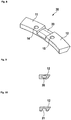
- Figure 1 shows a balancing weight 10 of a preferred embodiment.
- the body of the balancing weight comprises a center section 13 and preferably a first side wing 11 and a second side wing 12 to the sides of the center section.
- the material of the body is preferably a plastic material, which may be fiber reinforced, or any other lightweight material. It does not include a mass portion or any mass particles for increasing the weight.
- a clip 16 is provided preferably at the center section 13 for attaching the weight to a rim of a wheel. Accordingly, the clip is protruding from the center section.
- at least one hole 14, 15 may be provided, preferably within at least one of the side wings to grip the balancing weight by an automatic handling system or robot.
- the side wings are so short, that it is not possible to provide the holes 14, 15.
- a widely used standard distance between these holes is 24 mm.
- a typical 20 g balancing weight has a length of about 40 mm leaving sufficient space for the holes.
- a 10 g balancing weight which may have about 20 mm of length, could no more bear such holes. Smaller balancing weights would even no more allow attaching a clip, which typically has a width of 16 mm. Therefore, a 5 g clip-on balancing weight cannot be realized.
- Due to the lower density of the plastic material plastic balancing weights have a significant increased size over metal weights and therefore provide sufficient space for the holes and the clip. Therefore balancing weights having standard shape may be realized with low weights like 10 g or 5 g.
- the embodiment shown is a very simple embodiment, which can be manufactured easily by injection molding.
- the clip 16 may be a metal clip partially molded into the body.
- Figure 2 shows a sectional view of the preferred embodiment.
- the clip 16 is held within the center section of the body.
- Figure 3 shows a clip, which is preferably made of metal sheet like aluminum, iron or steel.
- the clip has a rim section 17 for attachment to the rim of a wheel. It further has a body section 18, which is integrated into the body of the balancing weight. It is further preferred, if there is at least one means for increasing the stability and the extraction force, which may be a hole 19a. During molding of the body, the plastic material protrudes the hole and fixes the clip to the body.
- Figure 4 shows a further embodiment of a clip.
- at least one cutout 19b may be provided. It may be combined with at least one hole as described above.
- FIG. 5 shows another embodiment with an integrated clip in a sectional view.
- clip 16 is an integral part of the body. It preferably comprises the same plastic material as the body. It is preferred, if at least the section of the clip 16 is fiber reinforced, for example by glass fibers or carbon fibers to increase its strength.
- Figure 6 shows another preferred embodiment with further reduced weight.
- the average density of the balancing weight may further be decreased by a hollow space 20, preferably within the sides of wings. It is preferred if the hollow space does not communicate with the holes 14, 15 and is totally enclosed in the plastic material. This embodiment allows to further increase the size of the balancing weights.
- Figure 7 shows another reduced weight embodiment.
- a groove or a recess 21 is preferably provided in at least one of the side wings 11, 12. This groove may communicate with at least one of the holes 14, 15. The groove may be closed to the sidewalls of the side wings, so they cannot be seen from the outside, when the balancing weight is attached to a rim.
- Figure 8 shows a balancing weight without clip. Its center section has a shape for holding a separate clip, which preferably is a metal clip for attaching the balancing weight to the rim of the wheel. This embodiment may have the same features as described above, except the clip.
- Figures 9 and 10 show further embodiments with a hollow space and a groove as described above.
Landscapes
- Engineering & Computer Science (AREA)
- General Engineering & Computer Science (AREA)
- Physics & Mathematics (AREA)
- Acoustics & Sound (AREA)
- Aviation & Aerospace Engineering (AREA)
- Mechanical Engineering (AREA)
- Golf Clubs (AREA)
- Connection Of Plates (AREA)
- Forms Removed On Construction Sites Or Auxiliary Members Thereof (AREA)
Description
- The invention relates to balancing weights, which may be attached to the rim of a wheel.
- Clip-on balancing weights as disclosed in the
US patent 4,728,154 have a body of a metal providing mass and a clip to hold the balancing weight to the rim of a wheel. Previously the bodies of balancing weights have been made from heavy metals like lead or iron. While lead has been prohibited in most states, iron is still in use. Iron weights have the disadvantage that they must be protected from corrosion. With modern cars, the maximum speeds increase. This requires more precise and more granular balancing of the wheels. Common lead or iron balancing weights get too small with low weight sizes to be handled easy and specifically to be automatically handled by robots. - In
GB 2 442 715 A - The embodiments are based on the object of providing a Balancing weight, which is lightweight and has a size big enough to be handled by an automatic handling system or robot.
- In an embodiment, the balancing weight has a body made of a plastic material. A clip may be provided for attaching the weight to a rim of a wheel. Preferably, the clip is at least partially enclosed within the body. It may be molded partially into the body. The clip may be of a metal like iron or steel or any other suitable material. The plastic material may be at least one of the groups of Polyethylene, Polypropylene, Polyamide, Polycarbonate, ABS, Polytetrafluorethylene or any other suitable plastic material. As the plastic material provides a lower density compared to lead, iron, or other high mass materials, the balancing weight may be made larger, so that it can easily be handled. There is no high mass filler or other component like a high mass rod having a significantly higher specific weight than the plastic material within the body, which would increase mass. As the clip preferably is of a thin sheet material, it does not significantly increase the overall mass. Furthermore, a plastic material has significant better corrosion characteristics and the metals and therefore has a long lifetime. Lost plastic balancing weights have less impact to the environment than lost lead weights. Preferably, the balancing weight is manufactured by injection molding.
- In a preferred embodiment, the clip has a structure, preferably at least one hole for anchoring within the body material.
- It is further preferred, if the balancing weight is made of a glass fiber or carbon fiber reinforced material.
- According to another embodiment, a clip for attaching the balancing weight to a rim is integrated into the body and preferably comprises of plastic material, most preferably of the same plastic material as the body.
- In a further embodiment, the balancing weight has at least one, preferably two holes for handling by an automatic handling system or by a robot.
- In another embodiment, the balancing weight has a hollow section.
- In a further embodiment, the balancing weight has a groove or a recess.
- In the following, the invention will be described by way of example, without limitation of the general inventive concept, on examples of embodiment and with reference to the drawings.
- Figure 1
- a balancing weight according to a preferred embodiment.
- Figure 2
- shows a sectional view of a preferred embodiment.
- Figure 3
- shows a first embodiment of a clip.
- Figure 4
- shows a second embodiment of a clip.
- Figure 5
- shows an embodiment with integrated clip.
- Figure 6
- shows another preferred embodiment with further reduced weight.
- Figure 7
- shows a further reduced weight embodiment.
- Figure 8
- shows another embodiment of a balancing weight.
- Figure 9
- shows a further embodiment with a hollow section.
- Figure 10
- shows a further embodiment with a recess.
- While the invention is susceptible to various modifications and alternative forms, specific embodiments thereof are shown by way of example in the drawings and will herein be described in detail. It should be understood, however, that the drawings and detailed description thereto are not intended to limit the invention to the particular form disclosed, but on the contrary, the intention is to cover all modifications, equivalents and alternatives falling within the spirit and scope of the present invention as defined by the appended claims.
-
Figure 1 shows a balancingweight 10 of a preferred embodiment. The body of the balancing weight comprises acenter section 13 and preferably afirst side wing 11 and asecond side wing 12 to the sides of the center section. The material of the body is preferably a plastic material, which may be fiber reinforced, or any other lightweight material. It does not include a mass portion or any mass particles for increasing the weight. Aclip 16 is provided preferably at thecenter section 13 for attaching the weight to a rim of a wheel. Accordingly, the clip is protruding from the center section. Furthermore, at least onehole holes clip 16 may be a metal clip partially molded into the body. -
Figure 2 shows a sectional view of the preferred embodiment. Here theclip 16 is held within the center section of the body. -
Figure 3 shows a clip, which is preferably made of metal sheet like aluminum, iron or steel. The clip has arim section 17 for attachment to the rim of a wheel. It further has abody section 18, which is integrated into the body of the balancing weight. It is further preferred, if there is at least one means for increasing the stability and the extraction force, which may be ahole 19a. During molding of the body, the plastic material protrudes the hole and fixes the clip to the body. -
Figure 4 shows a further embodiment of a clip. Here, instead of a hole, at least onecutout 19b may be provided. It may be combined with at least one hole as described above. -
Figure 5 shows another embodiment with an integrated clip in a sectional view. Here,clip 16 is an integral part of the body. It preferably comprises the same plastic material as the body. It is preferred, if at least the section of theclip 16 is fiber reinforced, for example by glass fibers or carbon fibers to increase its strength. -
Figure 6 shows another preferred embodiment with further reduced weight. The average density of the balancing weight may further be decreased by ahollow space 20, preferably within the sides of wings. It is preferred if the hollow space does not communicate with theholes -
Figure 7 shows another reduced weight embodiment. Here a groove or arecess 21 is preferably provided in at least one of theside wings holes -
Figure 8 shows a balancing weight without clip. Its center section has a shape for holding a separate clip, which preferably is a metal clip for attaching the balancing weight to the rim of the wheel. This embodiment may have the same features as described above, except the clip. -
Figures 9 and 10 show further embodiments with a hollow space and a groove as described above. -
- 10
- balancing weight
- 11
- first side wing.
- 12
- second side wing
- 13
- center section
- 14
- first hole
- 15
- second hole
- 16
- clip
- 17
- rim section
- 18
- body section
- 19a
- hole
- 19b
- cutout
- 20
- hollow space
- 21
- recess
- 30
- balancing weight without clip
- 33
- center section
Claims (11)
- Balancing weight (10) having a center section (13) and two side wings (11, 12) comprisinga plastic material without integrated mass portion or mass particles, anda clip for attaching the balancing weight to a rim of a wheel, the clip has a rim section (17) for attachment to the rim of a wheel and a body section (18) which is integrated into the body of the balancing weight.characterized in, thatthe body section (18) of the clip is integrated into the plastic material.
- Balancing weight according to claim 1,
characterized in, that
the clip is made from metal sheet. - Balancing weight according to claim 1,
characterized in, that
the clip is made from plastic material. - Balancing weight according to claim 3,
characterized in, that
the clip is an integral part of the center section (13). - Balancing weight according to any one of the previous claims,
characterized in, that
the clip has at least one hole (19a) or cut out (19b) to increase the pullout force. - Balancing weight according to any one of the previous claims,
characterized in, that
a hollow space (20) is provided in the balancing weight. - Balancing weight according to any one of the previous claims,
characterized in, that
said hollow space (20) is provided in at least one of the side wings. - Balancing weight according to any one of the previous claims,
characterized in, that
a groove or recess (21) is provided in the balancing weight. - Balancing weight according to any one of the previous claims,
characterized in, that
said groove or recess (21) is provided in at least one of the side wings. - Balancing weight according to any one of the previous claims,
characterized in, that
wherein the material of the balancing weight is at least partially fiber reinforced. - Balancing weight according to any one of the previous claims,
characterized in, that
wherein at least one hole (14, 15) for handling the balancing weight by an automatic handling system or robot is provided.
Priority Applications (3)
| Application Number | Priority Date | Filing Date | Title |
|---|---|---|---|
| EP12194090.2A EP2735763B1 (en) | 2012-11-23 | 2012-11-23 | Balancing weights |
| DE102013212541.0A DE102013212541A1 (en) | 2012-11-23 | 2013-06-27 | Set of balance weights with constant outer contour |
| CN201310596802.9A CN103832207B (en) | 2012-11-23 | 2013-11-22 | Balancing weight |
Applications Claiming Priority (1)
| Application Number | Priority Date | Filing Date | Title |
|---|---|---|---|
| EP12194090.2A EP2735763B1 (en) | 2012-11-23 | 2012-11-23 | Balancing weights |
Publications (2)
| Publication Number | Publication Date |
|---|---|
| EP2735763A1 EP2735763A1 (en) | 2014-05-28 |
| EP2735763B1 true EP2735763B1 (en) | 2017-08-09 |
Family
ID=47323923
Family Applications (1)
| Application Number | Title | Priority Date | Filing Date |
|---|---|---|---|
| EP12194090.2A Active EP2735763B1 (en) | 2012-11-23 | 2012-11-23 | Balancing weights |
Country Status (3)
| Country | Link |
|---|---|
| EP (1) | EP2735763B1 (en) |
| CN (1) | CN103832207B (en) |
| DE (1) | DE102013212541A1 (en) |
Families Citing this family (2)
| Publication number | Priority date | Publication date | Assignee | Title |
|---|---|---|---|---|
| EP2642155A1 (en) * | 2012-03-20 | 2013-09-25 | WEGMANN automotive GmbH & Co. KG | Magazine for balancing weights |
| CN105216543A (en) * | 2015-09-14 | 2016-01-06 | 泰州市华诚钨钼制品有限公司 | A kind of aircraft balance block |
Family Cites Families (9)
| Publication number | Priority date | Publication date | Assignee | Title |
|---|---|---|---|---|
| DE2411077A1 (en) * | 1974-03-08 | 1975-11-13 | Jaudas Fa Eugen | Balancing weight for car wheels - is extruded from a mixture of plastic and granulated heavy metal |
| US4728154A (en) | 1987-02-04 | 1988-03-01 | Motor Wheel Corporation | Balance weight for vehicle wheel |
| EP1302695A1 (en) * | 2001-10-11 | 2003-04-16 | BW Manufacturing Limited | Balance weight assembly |
| DE20119769U1 (en) | 2001-12-06 | 2002-03-21 | Bettchen, David, 42579 Heiligenhaus | Balance weight train for balancing vehicle wheels |
| DE102004017764A1 (en) | 2004-04-05 | 2005-10-27 | Gesellschaft Für Wolfram-Industrie Mbh | Wheel balancing weights |
| CN2732511Y (en) * | 2004-09-28 | 2005-10-12 | 青岛成友金属有限公司 | Automobile wheel counterbalancing mass |
| DE202005008160U1 (en) | 2005-05-20 | 2005-09-15 | Froehlich Martin | Balancing weight for car wheels is made from composite of plastic with embedded particles of another material, e.g. iron |
| NL1031510C2 (en) * | 2006-04-04 | 2007-10-05 | Fastron B V | Method and molds for manufacturing a device for balancing a vehicle wheel, also such a device. |
| GB2442715B (en) * | 2007-03-02 | 2011-10-12 | Trax Jh Ltd | Wheel balance assembly |
-
2012
- 2012-11-23 EP EP12194090.2A patent/EP2735763B1/en active Active
-
2013
- 2013-06-27 DE DE102013212541.0A patent/DE102013212541A1/en not_active Withdrawn
- 2013-11-22 CN CN201310596802.9A patent/CN103832207B/en active Active
Also Published As
| Publication number | Publication date |
|---|---|
| CN103832207B (en) | 2020-01-31 |
| EP2735763A1 (en) | 2014-05-28 |
| CN103832207A (en) | 2014-06-04 |
| DE102013212541A1 (en) | 2014-05-28 |
Similar Documents
| Publication | Publication Date | Title |
|---|---|---|
| KR101738039B1 (en) | Structure of hybrid-front pillar | |
| US9115778B2 (en) | Holder for a spring | |
| US8491427B2 (en) | Derailleur hanger with insertion aid | |
| US20130334841A1 (en) | Motor Vehicle Body With Stiffening Struts | |
| ES2533692T3 (en) | Vehicle wheel | |
| EP2003050A1 (en) | Handlebar with elastic hinges | |
| US9073501B2 (en) | Roller assembly for autonomous mobile robots | |
| US9341237B2 (en) | Bicycle chain connecting link | |
| CN106414104A (en) | Thermoplastic wheel hub and non-pneumatic tire | |
| WO2009137579A8 (en) | Utility vehicle with at least one storage bin | |
| WO2009137580A3 (en) | Suspension systems for a vehicle | |
| EP3534030A1 (en) | Brake caliper assembly having a retainer bracket | |
| CA2938749A1 (en) | Wheel chock with recessed gripping member | |
| EP2735763A1 (en) | Balancing weights | |
| US9949467B2 (en) | Fishing line guide | |
| US8403116B2 (en) | Protective pipe for a piston/cylinder unit | |
| US20160245148A1 (en) | Device for Accommodating a Muffler for a Two-Wheel Vehicle | |
| US20210080219A1 (en) | Bowfishing arrow slide | |
| WO2012157986A3 (en) | Bumper back beam for vehicle | |
| MXPA04007535A (en) | Composite helmet for body mount. | |
| US20140007383A1 (en) | Breakaway Rope Holder System and Method | |
| CN205527066U (en) | Novel wire rope recruitment character wheel | |
| KR101410330B1 (en) | Wheel for vehicle tire | |
| EP2913555B1 (en) | Linked clip-on balancing weights for vehicles | |
| KR101949320B1 (en) | Self-balancing balancing weight for wheel |
Legal Events
| Date | Code | Title | Description |
|---|---|---|---|
| PUAI | Public reference made under article 153(3) epc to a published international application that has entered the european phase |
Free format text: ORIGINAL CODE: 0009012 |
|
| 17P | Request for examination filed |
Effective date: 20121123 |
|
| AK | Designated contracting states |
Kind code of ref document: A1 Designated state(s): AL AT BE BG CH CY CZ DE DK EE ES FI FR GB GR HR HU IE IS IT LI LT LU LV MC MK MT NL NO PL PT RO RS SE SI SK SM TR |
|
| AX | Request for extension of the european patent |
Extension state: BA ME |
|
| R17P | Request for examination filed (corrected) |
Effective date: 20141128 |
|
| RBV | Designated contracting states (corrected) |
Designated state(s): AL AT BE BG CH CY CZ DE DK EE ES FI FR GB GR HR HU IE IS IT LI LT LU LV MC MK MT NL NO PL PT RO RS SE SI SK SM TR |
|
| GRAP | Despatch of communication of intention to grant a patent |
Free format text: ORIGINAL CODE: EPIDOSNIGR1 |
|
| STAA | Information on the status of an ep patent application or granted ep patent |
Free format text: STATUS: GRANT OF PATENT IS INTENDED |
|
| INTG | Intention to grant announced |
Effective date: 20170118 |
|
| GRAS | Grant fee paid |
Free format text: ORIGINAL CODE: EPIDOSNIGR3 |
|
| GRAA | (expected) grant |
Free format text: ORIGINAL CODE: 0009210 |
|
| STAA | Information on the status of an ep patent application or granted ep patent |
Free format text: STATUS: THE PATENT HAS BEEN GRANTED |
|
| AK | Designated contracting states |
Kind code of ref document: B1 Designated state(s): AL AT BE BG CH CY CZ DE DK EE ES FI FR GB GR HR HU IE IS IT LI LT LU LV MC MK MT NL NO PL PT RO RS SE SI SK SM TR |
|
| REG | Reference to a national code |
Ref country code: GB Ref legal event code: FG4D |
|
| REG | Reference to a national code |
Ref country code: CH Ref legal event code: EP Ref country code: AT Ref legal event code: REF Ref document number: 917206 Country of ref document: AT Kind code of ref document: T Effective date: 20170815 |
|
| REG | Reference to a national code |
Ref country code: IE Ref legal event code: FG4D |
|
| REG | Reference to a national code |
Ref country code: DE Ref legal event code: R096 Ref document number: 602012035578 Country of ref document: DE |
|
| REG | Reference to a national code |
Ref country code: NL Ref legal event code: MP Effective date: 20170809 |
|
| REG | Reference to a national code |
Ref country code: LT Ref legal event code: MG4D |
|
| REG | Reference to a national code |
Ref country code: AT Ref legal event code: MK05 Ref document number: 917206 Country of ref document: AT Kind code of ref document: T Effective date: 20170809 |
|
| PG25 | Lapsed in a contracting state [announced via postgrant information from national office to epo] |
Ref country code: HR Free format text: LAPSE BECAUSE OF FAILURE TO SUBMIT A TRANSLATION OF THE DESCRIPTION OR TO PAY THE FEE WITHIN THE PRESCRIBED TIME-LIMIT Effective date: 20170809 Ref country code: FI Free format text: LAPSE BECAUSE OF FAILURE TO SUBMIT A TRANSLATION OF THE DESCRIPTION OR TO PAY THE FEE WITHIN THE PRESCRIBED TIME-LIMIT Effective date: 20170809 Ref country code: NO Free format text: LAPSE BECAUSE OF FAILURE TO SUBMIT A TRANSLATION OF THE DESCRIPTION OR TO PAY THE FEE WITHIN THE PRESCRIBED TIME-LIMIT Effective date: 20171109 Ref country code: NL Free format text: LAPSE BECAUSE OF FAILURE TO SUBMIT A TRANSLATION OF THE DESCRIPTION OR TO PAY THE FEE WITHIN THE PRESCRIBED TIME-LIMIT Effective date: 20170809 Ref country code: SE Free format text: LAPSE BECAUSE OF FAILURE TO SUBMIT A TRANSLATION OF THE DESCRIPTION OR TO PAY THE FEE WITHIN THE PRESCRIBED TIME-LIMIT Effective date: 20170809 Ref country code: LT Free format text: LAPSE BECAUSE OF FAILURE TO SUBMIT A TRANSLATION OF THE DESCRIPTION OR TO PAY THE FEE WITHIN THE PRESCRIBED TIME-LIMIT Effective date: 20170809 Ref country code: AT Free format text: LAPSE BECAUSE OF FAILURE TO SUBMIT A TRANSLATION OF THE DESCRIPTION OR TO PAY THE FEE WITHIN THE PRESCRIBED TIME-LIMIT Effective date: 20170809 |
|
| PG25 | Lapsed in a contracting state [announced via postgrant information from national office to epo] |
Ref country code: IS Free format text: LAPSE BECAUSE OF FAILURE TO SUBMIT A TRANSLATION OF THE DESCRIPTION OR TO PAY THE FEE WITHIN THE PRESCRIBED TIME-LIMIT Effective date: 20171209 Ref country code: LV Free format text: LAPSE BECAUSE OF FAILURE TO SUBMIT A TRANSLATION OF THE DESCRIPTION OR TO PAY THE FEE WITHIN THE PRESCRIBED TIME-LIMIT Effective date: 20170809 Ref country code: GR Free format text: LAPSE BECAUSE OF FAILURE TO SUBMIT A TRANSLATION OF THE DESCRIPTION OR TO PAY THE FEE WITHIN THE PRESCRIBED TIME-LIMIT Effective date: 20171110 Ref country code: PL Free format text: LAPSE BECAUSE OF FAILURE TO SUBMIT A TRANSLATION OF THE DESCRIPTION OR TO PAY THE FEE WITHIN THE PRESCRIBED TIME-LIMIT Effective date: 20170809 Ref country code: RS Free format text: LAPSE BECAUSE OF FAILURE TO SUBMIT A TRANSLATION OF THE DESCRIPTION OR TO PAY THE FEE WITHIN THE PRESCRIBED TIME-LIMIT Effective date: 20170809 Ref country code: BG Free format text: LAPSE BECAUSE OF FAILURE TO SUBMIT A TRANSLATION OF THE DESCRIPTION OR TO PAY THE FEE WITHIN THE PRESCRIBED TIME-LIMIT Effective date: 20171109 Ref country code: ES Free format text: LAPSE BECAUSE OF FAILURE TO SUBMIT A TRANSLATION OF THE DESCRIPTION OR TO PAY THE FEE WITHIN THE PRESCRIBED TIME-LIMIT Effective date: 20170809 |
|
| PG25 | Lapsed in a contracting state [announced via postgrant information from national office to epo] |
Ref country code: RO Free format text: LAPSE BECAUSE OF FAILURE TO SUBMIT A TRANSLATION OF THE DESCRIPTION OR TO PAY THE FEE WITHIN THE PRESCRIBED TIME-LIMIT Effective date: 20170809 Ref country code: CZ Free format text: LAPSE BECAUSE OF FAILURE TO SUBMIT A TRANSLATION OF THE DESCRIPTION OR TO PAY THE FEE WITHIN THE PRESCRIBED TIME-LIMIT Effective date: 20170809 Ref country code: DK Free format text: LAPSE BECAUSE OF FAILURE TO SUBMIT A TRANSLATION OF THE DESCRIPTION OR TO PAY THE FEE WITHIN THE PRESCRIBED TIME-LIMIT Effective date: 20170809 |
|
| REG | Reference to a national code |
Ref country code: DE Ref legal event code: R097 Ref document number: 602012035578 Country of ref document: DE |
|
| PG25 | Lapsed in a contracting state [announced via postgrant information from national office to epo] |
Ref country code: SM Free format text: LAPSE BECAUSE OF FAILURE TO SUBMIT A TRANSLATION OF THE DESCRIPTION OR TO PAY THE FEE WITHIN THE PRESCRIBED TIME-LIMIT Effective date: 20170809 Ref country code: IT Free format text: LAPSE BECAUSE OF FAILURE TO SUBMIT A TRANSLATION OF THE DESCRIPTION OR TO PAY THE FEE WITHIN THE PRESCRIBED TIME-LIMIT Effective date: 20170809 Ref country code: EE Free format text: LAPSE BECAUSE OF FAILURE TO SUBMIT A TRANSLATION OF THE DESCRIPTION OR TO PAY THE FEE WITHIN THE PRESCRIBED TIME-LIMIT Effective date: 20170809 Ref country code: SK Free format text: LAPSE BECAUSE OF FAILURE TO SUBMIT A TRANSLATION OF THE DESCRIPTION OR TO PAY THE FEE WITHIN THE PRESCRIBED TIME-LIMIT Effective date: 20170809 |
|
| PLBE | No opposition filed within time limit |
Free format text: ORIGINAL CODE: 0009261 |
|
| STAA | Information on the status of an ep patent application or granted ep patent |
Free format text: STATUS: NO OPPOSITION FILED WITHIN TIME LIMIT |
|
| PG25 | Lapsed in a contracting state [announced via postgrant information from national office to epo] |
Ref country code: MC Free format text: LAPSE BECAUSE OF FAILURE TO SUBMIT A TRANSLATION OF THE DESCRIPTION OR TO PAY THE FEE WITHIN THE PRESCRIBED TIME-LIMIT Effective date: 20170809 |
|
| 26N | No opposition filed |
Effective date: 20180511 |
|
| GBPC | Gb: european patent ceased through non-payment of renewal fee |
Effective date: 20171123 |
|
| PG25 | Lapsed in a contracting state [announced via postgrant information from national office to epo] |
Ref country code: LI Free format text: LAPSE BECAUSE OF NON-PAYMENT OF DUE FEES Effective date: 20171130 Ref country code: CH Free format text: LAPSE BECAUSE OF NON-PAYMENT OF DUE FEES Effective date: 20171130 |
|
| PG25 | Lapsed in a contracting state [announced via postgrant information from national office to epo] |
Ref country code: SI Free format text: LAPSE BECAUSE OF FAILURE TO SUBMIT A TRANSLATION OF THE DESCRIPTION OR TO PAY THE FEE WITHIN THE PRESCRIBED TIME-LIMIT Effective date: 20170809 Ref country code: LU Free format text: LAPSE BECAUSE OF NON-PAYMENT OF DUE FEES Effective date: 20171123 |
|
| REG | Reference to a national code |
Ref country code: FR Ref legal event code: ST Effective date: 20180731 Ref country code: BE Ref legal event code: MM Effective date: 20171130 |
|
| REG | Reference to a national code |
Ref country code: IE Ref legal event code: MM4A |
|
| PG25 | Lapsed in a contracting state [announced via postgrant information from national office to epo] |
Ref country code: MT Free format text: LAPSE BECAUSE OF NON-PAYMENT OF DUE FEES Effective date: 20171123 |
|
| PG25 | Lapsed in a contracting state [announced via postgrant information from national office to epo] |
Ref country code: IE Free format text: LAPSE BECAUSE OF NON-PAYMENT OF DUE FEES Effective date: 20171123 Ref country code: FR Free format text: LAPSE BECAUSE OF NON-PAYMENT OF DUE FEES Effective date: 20171130 |
|
| PG25 | Lapsed in a contracting state [announced via postgrant information from national office to epo] |
Ref country code: BE Free format text: LAPSE BECAUSE OF NON-PAYMENT OF DUE FEES Effective date: 20171130 Ref country code: GB Free format text: LAPSE BECAUSE OF NON-PAYMENT OF DUE FEES Effective date: 20171123 |
|
| PG25 | Lapsed in a contracting state [announced via postgrant information from national office to epo] |
Ref country code: HU Free format text: LAPSE BECAUSE OF FAILURE TO SUBMIT A TRANSLATION OF THE DESCRIPTION OR TO PAY THE FEE WITHIN THE PRESCRIBED TIME-LIMIT; INVALID AB INITIO Effective date: 20121123 |
|
| PG25 | Lapsed in a contracting state [announced via postgrant information from national office to epo] |
Ref country code: CY Free format text: LAPSE BECAUSE OF NON-PAYMENT OF DUE FEES Effective date: 20170809 |
|
| PG25 | Lapsed in a contracting state [announced via postgrant information from national office to epo] |
Ref country code: MK Free format text: LAPSE BECAUSE OF FAILURE TO SUBMIT A TRANSLATION OF THE DESCRIPTION OR TO PAY THE FEE WITHIN THE PRESCRIBED TIME-LIMIT Effective date: 20170809 |
|
| PG25 | Lapsed in a contracting state [announced via postgrant information from national office to epo] |
Ref country code: TR Free format text: LAPSE BECAUSE OF FAILURE TO SUBMIT A TRANSLATION OF THE DESCRIPTION OR TO PAY THE FEE WITHIN THE PRESCRIBED TIME-LIMIT Effective date: 20170809 |
|
| PG25 | Lapsed in a contracting state [announced via postgrant information from national office to epo] |
Ref country code: PT Free format text: LAPSE BECAUSE OF FAILURE TO SUBMIT A TRANSLATION OF THE DESCRIPTION OR TO PAY THE FEE WITHIN THE PRESCRIBED TIME-LIMIT Effective date: 20170809 |
|
| PG25 | Lapsed in a contracting state [announced via postgrant information from national office to epo] |
Ref country code: AL Free format text: LAPSE BECAUSE OF FAILURE TO SUBMIT A TRANSLATION OF THE DESCRIPTION OR TO PAY THE FEE WITHIN THE PRESCRIBED TIME-LIMIT Effective date: 20170809 |
|
| REG | Reference to a national code |
Ref country code: DE Ref legal event code: R081 Ref document number: 602012035578 Country of ref document: DE Owner name: WEGMANN AUTOMOTIVE GMBH, DE Free format text: FORMER OWNER: WEGMANN AUTOMOTIVE GMBH & CO. KG, 97209 VEITSHOECHHEIM, DE |
|
| PGFP | Annual fee paid to national office [announced via postgrant information from national office to epo] |
Ref country code: DE Payment date: 20251121 Year of fee payment: 14 |