EP2003050A1 - Handlebar with elastic hinges - Google Patents
Handlebar with elastic hinges Download PDFInfo
- Publication number
- EP2003050A1 EP2003050A1 EP07425378A EP07425378A EP2003050A1 EP 2003050 A1 EP2003050 A1 EP 2003050A1 EP 07425378 A EP07425378 A EP 07425378A EP 07425378 A EP07425378 A EP 07425378A EP 2003050 A1 EP2003050 A1 EP 2003050A1
- Authority
- EP
- European Patent Office
- Prior art keywords
- handlebar
- intermediate portion
- section
- cross
- central portion
- Prior art date
- Legal status (The legal status is an assumption and is not a legal conclusion. Google has not performed a legal analysis and makes no representation as to the accuracy of the status listed.)
- Withdrawn
Links
Images
Classifications
-
- B—PERFORMING OPERATIONS; TRANSPORTING
- B62—LAND VEHICLES FOR TRAVELLING OTHERWISE THAN ON RAILS
- B62K—CYCLES; CYCLE FRAMES; CYCLE STEERING DEVICES; RIDER-OPERATED TERMINAL CONTROLS SPECIALLY ADAPTED FOR CYCLES; CYCLE AXLE SUSPENSIONS; CYCLE SIDE-CARS, FORECARS, OR THE LIKE
- B62K21/00—Steering devices
- B62K21/12—Handlebars; Handlebar stems
- B62K21/14—Handlebars; Handlebar stems having resilient parts therein
- B62K21/145—Handlebars; Handlebar stems having resilient parts therein the handlebar itself being flexible
-
- Y—GENERAL TAGGING OF NEW TECHNOLOGICAL DEVELOPMENTS; GENERAL TAGGING OF CROSS-SECTIONAL TECHNOLOGIES SPANNING OVER SEVERAL SECTIONS OF THE IPC; TECHNICAL SUBJECTS COVERED BY FORMER USPC CROSS-REFERENCE ART COLLECTIONS [XRACs] AND DIGESTS
- Y10—TECHNICAL SUBJECTS COVERED BY FORMER USPC
- Y10T—TECHNICAL SUBJECTS COVERED BY FORMER US CLASSIFICATION
- Y10T74/00—Machine element or mechanism
- Y10T74/20—Control lever and linkage systems
- Y10T74/20576—Elements
- Y10T74/20732—Handles
- Y10T74/2078—Handle bars
Definitions
- the present invention relates to a handlebar in accordance with the introduction to the main claim.
- Handlebars comprising a central portion and end portions, said central portion and each end portion being connected together by a corresponding intermediate portion having its axis inclined to the adjacent portions.
- handlebars are known with a rectilinear central portion, with each intermediate portion and end portion having its own different inclination to the adjacent portion.
- variable cross-section does not allow crossbars to be fixed to them to stiffen the handlebar.
- An object of the present invention is to provide a handlebar which is an improvement if compared to the known handlebars.
- An object of the present invention is to provide a handlebar of the stated type which has a capacity to deform in a controlled manner as a result of stresses which it receives during the use of the vehicle on which it is mounted.
- Another object is to provide a handlebar of the stated type with which a usual crossbar can be associated.
- a handlebar according to the invention is indicated overall by 1 and comprises a body 2 presenting a central portion 3, two end portions 4 and 5 and intermediate portions 7 and 8 connecting the central portion 3 to corresponding end portions.
- the portions 3, 4, 5, 7 and 8 (see Figure 1 ) all have a constant cross-section and are disposed with their longitudinal axes K, W (for the portions 4 and 5) and F (for the portions 7 and 8) at an angle between them.
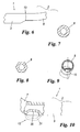
- the cross-section of said portions is not necessarily constant; for example, at least part of the said portions can have a cross-section which is circular (as in Figure 7 ), polygonal (i.e.
- sudden cross-section variations are present at opposing end regions 12 and 13 of each intermediate portion 7 and 8 of the body 2, to define elastic regions acting as elastic hinges.
- These end regions acting as elastic hinges 12, 13 are present at the central portions 3 or end portions 4 or 5 where the corresponding intermediate portions connect to these latter.
- the handlebar can deform elastically in a controlled manner when the body 2 is subjected to stresses (of any type) during movement of the vehicle along the ground.
- Said end regions 12, 13 can assume various forms: as a step with edges at 90° to the longitudinal axis of the adjacent central or end portion ( Figure 1 and Figure 2 ); as an inclined surface along only a part of the intermediate portion ( Figure 6 ), this offering a differentiated response by the handlebar to different stresses; or conical ( Figure 3, Figure 4 and Figure 5 ).
- the end regions 12,1 3 acting as elastic hinges involve a small part of the intermediate portion, for example from 5 to 10 cm measured from the point of contact with the adjacent portion, while the remaining part of the intermediate portion is of constant cross-section.
- hinges can also be obtained by creating localized recesses 20 at the regions 12 and 13 or projections 21 in these latter ( Figure 10 ).
- the geometry of the end portions or hinges 12, 13 enables a characteristic dynamic to be given to the handlebar which differs on the basis of the type of action being performed. This maintains high handlebar functionality because, if necessary, a usual collar can be securely fixed onto the two handlebar intermediate portions of constant cross-section, for mounting the strengthening crossbar.
Abstract
Description
- The present invention relates to a handlebar in accordance with the introduction to the main claim.
- Handlebars are known comprising a central portion and end portions, said central portion and each end portion being connected together by a corresponding intermediate portion having its axis inclined to the adjacent portions. In particular, handlebars are known with a rectilinear central portion, with each intermediate portion and end portion having its own different inclination to the adjacent portion.
- These handlebars, with portions of constant and/or variable cross-section, are described for example in
US5117707 ,US5257552 ,US5950497 andUS5064157 . By using said handlebars it has been found that, while optimally fulfilling their purpose, they present a considerable rigidity particularly in the connection regions between two adjacent portions. This rigidity leads to a consequent uncontrolled deformation capacity of the handlebar, depending on is use and the vehicle type. - In addition, the presence of the intermediate portions of variable cross-section does not allow crossbars to be fixed to them to stiffen the handlebar.
- An object of the present invention is to provide a handlebar which is an improvement if compared to the known handlebars.
- An object of the present invention is to provide a handlebar of the stated type which has a capacity to deform in a controlled manner as a result of stresses which it receives during the use of the vehicle on which it is mounted.
- Another object is to provide a handlebar of the stated type with which a usual crossbar can be associated.
- These and further objects which will be apparent to the expert of the art are attained by a handlebar in accordance with the accompanying claims.
- The present invention will be more apparent from the accompanying drawings, which are provided by way of non-limiting example and in which:
-
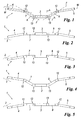
Figure 1 is a front view of a handlebar according to the invention; -
Figure 2 is a view of the handlebar ofFigure 1 seen from above; -
Figure 3 is a view of a first variant of the handlebar ofFigure 1 seen from above; -
Figure 4 is a front view of a second variant of the handlebar ofFigure 1 ; -
Figure 5 is a view of the second variant of the handlebar ofFigure 1 seen from above; -
Figure 6 is a front view of a detail of another variant of the handlebar ofFigure 1 ; -
Figures 7, 8 and 9 show various cross-sections, taken on the line 7-7 ofFigure 1 , through a part of the handlebar ofFigure 1 ; and -
Figure 10 is a front view of a detail of a further variant of the handlebar ofFigure 1 . - With reference to said figures, a handlebar according to the invention is indicated overall by 1 and comprises a
body 2 presenting acentral portion 3, twoend portions intermediate portions central portion 3 to corresponding end portions. Theportions Figure 1 ) all have a constant cross-section and are disposed with their longitudinal axes K, W (for theportions 4 and 5) and F (for theportions 7 and 8) at an angle between them. The cross-section of said portions is not necessarily constant; for example, at least part of the said portions can have a cross-section which is circular (as inFigure 7 ), polygonal (i.e. triangular, square or multi-sided, as inFigure 8 ) or with longitudinal recesses or flattenings (with therecess 10 visible in the case ofFigure 9 ). If the cross-section presents arecess 10, this can house an electric cable or a control cable connected to a control member or device associated with one of theend portions - According to the invention, sudden cross-section variations are present at
opposing end regions intermediate portion body 2, to define elastic regions acting as elastic hinges. These end regions acting aselastic hinges central portions 3 orend portions body 2 is subjected to stresses (of any type) during movement of the vehicle along the ground. - Said
end regions Figure 1 and Figure 2 ); as an inclined surface along only a part of the intermediate portion (Figure 6 ), this offering a differentiated response by the handlebar to different stresses; or conical (Figure 3, Figure 4 and Figure 5 ). Theend regions - These hinges can also be obtained by creating localized
recesses 20 at theregions projections 21 in these latter (Figure 10 ). - By virtue of the invention, as the task of the handlebar is to transmit to the member determining the vehicle trajectory (front wheel, rudder, guide shoe, etc.) the forces which the driver applies to determine this vehicle trajectory, and also to transmit to the driver all the travel stresses which are not damped by the appropriate shock absorbers if these are used (suspensions for motor vehicles, snowmobiles, etc.), the geometry of the end portions or
hinges - Some particular embodiments of the invention have been described. Others are however possible and are to be considered as fatting within the scope of the ensuing claims.
Claims (11)
- A handlebar (1) for a vehicle such as a motorcycle or a two, three or four wheeled motor vehicle, a snowmobile or a seamobile, comprising a body (2) presenting a central portion (3) and end portions (4, 5) of constant cross-section, the central portion (3) and each end portion (4, 5) being connected together by a corresponding intermediate portion (7, 8) also of constant cross-section, characterised in that each intermediate portion (7, 9) presents, in proximity to the central portion (3) and to the corresponding end portion (4, 5), end portions (12, 13) having sudden cross-section variations such as to define elastic regions acting as elastic hinges for the connection of said intermediate portion (7, 8) to the adjacent portions (4, 5), and to enable the handlebar (1) to undergo a controlled deformation thereat when subjected to stress during vehicle use.
- A handlebar as claimed in claim 1, characterised in that said sudden cross-section variation is defined by a step with edges at 90° to the longitudinal axis (K, W) of the central portion (3) or adjacent end portion (4, 5).
- A handlebar as claimed in claim 1, characterised in that said sudden cross-section variation is defined by a connection in the form of an inclined surface between the intermediate portion (7, 8) and the adjacent portion (3, 4, 5).
- A handlebar as claimed in claim 1, characterised in that said sudden cross-section variation is defined by a connection in the form of an inclined surface present on only a part of the intermediate portion (7, 8) at the adjacent portion (3, 4, 5).
- A handlebar as claimed in claim 1, characterised in that said sudden cross-section variation is defined by connection of conical pattern between the intermediate portion (7, 8) and the adjacent portion (3, 4, 5).
- A handlebar as claimed in claim 1, characterised in that said sudden cross-section variation is defined by a recess (20) localized in the end region (12, 13) of the intermediate portion (7, 8).
- A handlebar as claimed in claim 1, characterised in that said sudden cross-section variation is defined by a projection or thickening in the end region (12, 13) of the intermediate portion (7, 8).
- A handlebar as claimed in claim 1, characterised in that at least one from among the central portion (3), each intermediate portion (7, 8) and each end region (4, 5) has, at least on one part thereof, a circular cross-section.
- A handlebar as claimed in claim 1, characterised in that at least one from among the central portion (3), each intermediate portion (7, 8) and each end region (4, 5) has, at least on one part thereof, a polygonal cross-section.
- A handlebar as claimed in claim 1, characterised in that at least one from among the central portion (3), each intermediate portion (7, 8) and each end region (4, 5) presents a longitudinal recess (10) on at least one part thereof.
- A handlebar as claimed in claim 1, characterised in that at least one part of at least one from among the central portion (3), each intermediate portion (7, 8) and each end region (4, 5) presents a longitudinal flattening.
Priority Applications (8)
| Application Number | Priority Date | Filing Date | Title |
|---|---|---|---|
| EP07425378A EP2003050A1 (en) | 2007-06-15 | 2007-06-15 | Handlebar with elastic hinges |
| US12/664,752 US20100186543A1 (en) | 2007-06-15 | 2008-06-04 | Handlebar With Elastic Hinges |
| PCT/EP2008/056929 WO2008151974A1 (en) | 2007-06-15 | 2008-06-04 | Handlebar with elastic hinges |
| AT08760509T ATE485999T1 (en) | 2007-06-15 | 2008-06-04 | HANDLEBAR WITH SPRING HINGES |
| CN200880020269A CN101730643A (en) | 2007-06-15 | 2008-06-04 | Handlebar with elastic hinges |
| EP08760509A EP2162345B1 (en) | 2007-06-15 | 2008-06-04 | Handlebar with elastic hinges |
| DE602008003230T DE602008003230D1 (en) | 2007-06-15 | 2008-06-04 | HANDLEBAR WITH FEATHER HINGES |
| TW097122034A TW200900313A (en) | 2007-06-15 | 2008-06-13 | Handlebar with elastic hinges |
Applications Claiming Priority (1)
| Application Number | Priority Date | Filing Date | Title |
|---|---|---|---|
| EP07425378A EP2003050A1 (en) | 2007-06-15 | 2007-06-15 | Handlebar with elastic hinges |
Publications (1)
| Publication Number | Publication Date |
|---|---|
| EP2003050A1 true EP2003050A1 (en) | 2008-12-17 |
Family
ID=38441385
Family Applications (2)
| Application Number | Title | Priority Date | Filing Date |
|---|---|---|---|
| EP07425378A Withdrawn EP2003050A1 (en) | 2007-06-15 | 2007-06-15 | Handlebar with elastic hinges |
| EP08760509A Not-in-force EP2162345B1 (en) | 2007-06-15 | 2008-06-04 | Handlebar with elastic hinges |
Family Applications After (1)
| Application Number | Title | Priority Date | Filing Date |
|---|---|---|---|
| EP08760509A Not-in-force EP2162345B1 (en) | 2007-06-15 | 2008-06-04 | Handlebar with elastic hinges |
Country Status (7)
| Country | Link |
|---|---|
| US (1) | US20100186543A1 (en) |
| EP (2) | EP2003050A1 (en) |
| CN (1) | CN101730643A (en) |
| AT (1) | ATE485999T1 (en) |
| DE (1) | DE602008003230D1 (en) |
| TW (1) | TW200900313A (en) |
| WO (1) | WO2008151974A1 (en) |
Cited By (3)
| Publication number | Priority date | Publication date | Assignee | Title |
|---|---|---|---|---|
| EP2364902A3 (en) * | 2010-03-12 | 2011-10-12 | Trek Bicycle Corporation | Bicycle handlebar and grip assembly |
| FR3013308A1 (en) * | 2013-11-18 | 2015-05-22 | Neken | HANDLEBAR FOR A VEHICLE |
| US9061728B2 (en) | 2010-03-12 | 2015-06-23 | Trek Bicycle Corporation | Bicycle handlebar and grip assembly |
Families Citing this family (18)
| Publication number | Priority date | Publication date | Assignee | Title |
|---|---|---|---|---|
| JP2010167924A (en) * | 2009-01-23 | 2010-08-05 | Kyoei Seisakusho:Kk | Handle bar and method of manufacturing the same |
| CN103395464A (en) * | 2013-08-14 | 2013-11-20 | 张学田 | Bike spring shock-absorbing handle |
| USD777625S1 (en) * | 2015-08-12 | 2017-01-31 | Chia Hsiung Chang | Handlebar |
| USD856228S1 (en) * | 2016-02-29 | 2019-08-13 | Kevin Dunn | Motorcycle handlebar |
| USD907723S1 (en) * | 2016-07-19 | 2021-01-12 | Barton Innovations, Llc | Pair of spaced-apart exercise handles |
| AU201615114S (en) * | 2016-09-12 | 2017-03-16 | Bicycle handlebar | |
| US10426994B1 (en) | 2018-09-05 | 2019-10-01 | Total Gym Global Corp. | Exercise device handle and method of using same |
| USD843506S1 (en) * | 2018-09-05 | 2019-03-19 | Total Gym Global Corp. | Exercise device handle |
| USD925665S1 (en) | 2019-05-14 | 2021-07-20 | Barton Innovations, Llc | Elongated exercise bar |
| USD924988S1 (en) | 2019-05-14 | 2021-07-13 | Barton Innovations, Llc | Inverted V-shaped exercise bar |
| USD908818S1 (en) | 2019-05-14 | 2021-01-26 | Barton Innovations, Llc | Winged exercise bar |
| USD969043S1 (en) * | 2021-01-21 | 2022-11-08 | Paul Yaffe | Motorcycle handlebars |
| USD968285S1 (en) * | 2021-01-21 | 2022-11-01 | Paul Yaffe | Motorcycle handlebars |
| USD968284S1 (en) * | 2021-01-21 | 2022-11-01 | Paul Yaffe | Motorcycle handlebars |
| USD958709S1 (en) * | 2021-01-21 | 2022-07-26 | Paul Yaffe | Motorcycle handlebars |
| USD968286S1 (en) * | 2021-01-21 | 2022-11-01 | Paul Yaffe | Motorcycle handlebars |
| USD968287S1 (en) * | 2021-01-21 | 2022-11-01 | Paul Yaffe | Motorcycle handlebars |
| USD1002458S1 (en) * | 2021-07-14 | 2023-10-24 | F.I.V. Fabbrica Italiana Velocipedi Edoardo Bianchi S.P.A. | Handlebar for cycles or motorcycles |
Citations (3)
| Publication number | Priority date | Publication date | Assignee | Title |
|---|---|---|---|---|
| US565696A (en) * | 1896-08-11 | Stopping or starting device for elevators | ||
| WO1992020565A1 (en) * | 1991-05-20 | 1992-11-26 | Anthony Robert Stock | A handlebar for a cycle |
| DE4323501A1 (en) * | 1993-07-14 | 1995-01-19 | Bayerische Motoren Werke Ag | Handlebars, in particular for two-wheeled vehicles |
Family Cites Families (10)
| Publication number | Priority date | Publication date | Assignee | Title |
|---|---|---|---|---|
| GB565696A (en) * | 1942-02-16 | 1944-11-23 | Frank Wagner Schwinn | Improvements in or relating to handlebars for bicycles and the like, and to methods of assembling a handlebar |
| US5064157A (en) * | 1990-05-01 | 1991-11-12 | Jim O'neal Distributing, Inc. | Mounting bracket for handlebar crossbar |
| US5257552A (en) * | 1992-02-10 | 1993-11-02 | Answer Products, Inc. | Handlebars for bicycles, motorcycles, all terrain bikes, all terrain vehicles and jet skis |
| FR2690128A1 (en) * | 1992-04-16 | 1993-10-22 | Tunesi Sa Roger | Semi-flexible handlebar for mountain cycles |
| FR2690127B1 (en) * | 1992-04-16 | 1995-01-13 | Roger Tunesi | Handlebar hanger provided with zones forming articulations for the handles, and cycle equipped with such handlebar hanger. |
| US5950497A (en) * | 1996-10-02 | 1999-09-14 | Gustav Magenwirth Gmbh & Co. | Handlebar for vehicles |
| JPH10230885A (en) * | 1997-02-21 | 1998-09-02 | Takashi Nansai | Handle interlocking mechanism for bicycle |
| ES2270327T3 (en) * | 2004-03-15 | 2007-04-01 | Hi-Line S.R.L. | HANDLEBAR FOR BICYCLES AND MOTORCYCLES. |
| FR2868388B1 (en) * | 2004-04-01 | 2007-08-03 | Jean Baptiste Allexant | ERGONOMIC BICYCLE HANDLEBAR |
| DE102004050554A1 (en) * | 2004-10-16 | 2006-04-20 | Volkswagen Ag | Adjustable handlebar comprising steering rod, middle segment and handle grips |
-
2007
- 2007-06-15 EP EP07425378A patent/EP2003050A1/en not_active Withdrawn
-
2008
- 2008-06-04 AT AT08760509T patent/ATE485999T1/en not_active IP Right Cessation
- 2008-06-04 CN CN200880020269A patent/CN101730643A/en active Pending
- 2008-06-04 WO PCT/EP2008/056929 patent/WO2008151974A1/en active Application Filing
- 2008-06-04 US US12/664,752 patent/US20100186543A1/en not_active Abandoned
- 2008-06-04 EP EP08760509A patent/EP2162345B1/en not_active Not-in-force
- 2008-06-04 DE DE602008003230T patent/DE602008003230D1/en active Active
- 2008-06-13 TW TW097122034A patent/TW200900313A/en unknown
Patent Citations (3)
| Publication number | Priority date | Publication date | Assignee | Title |
|---|---|---|---|---|
| US565696A (en) * | 1896-08-11 | Stopping or starting device for elevators | ||
| WO1992020565A1 (en) * | 1991-05-20 | 1992-11-26 | Anthony Robert Stock | A handlebar for a cycle |
| DE4323501A1 (en) * | 1993-07-14 | 1995-01-19 | Bayerische Motoren Werke Ag | Handlebars, in particular for two-wheeled vehicles |
Cited By (3)
| Publication number | Priority date | Publication date | Assignee | Title |
|---|---|---|---|---|
| EP2364902A3 (en) * | 2010-03-12 | 2011-10-12 | Trek Bicycle Corporation | Bicycle handlebar and grip assembly |
| US9061728B2 (en) | 2010-03-12 | 2015-06-23 | Trek Bicycle Corporation | Bicycle handlebar and grip assembly |
| FR3013308A1 (en) * | 2013-11-18 | 2015-05-22 | Neken | HANDLEBAR FOR A VEHICLE |
Also Published As
| Publication number | Publication date |
|---|---|
| US20100186543A1 (en) | 2010-07-29 |
| EP2162345B1 (en) | 2010-10-27 |
| TW200900313A (en) | 2009-01-01 |
| ATE485999T1 (en) | 2010-11-15 |
| CN101730643A (en) | 2010-06-09 |
| EP2162345A1 (en) | 2010-03-17 |
| DE602008003230D1 (en) | 2010-12-09 |
| WO2008151974A1 (en) | 2008-12-18 |
Similar Documents
| Publication | Publication Date | Title |
|---|---|---|
| EP2003050A1 (en) | Handlebar with elastic hinges | |
| US9079610B2 (en) | Telescopic device of steering column for vehicle | |
| US9561699B2 (en) | Chassis link for a motor vehicle | |
| EP1598258A3 (en) | Vehicle control system | |
| CN105392637A (en) | Device for improving the safety of a vehicle | |
| US11396342B2 (en) | Front suspension of the telescopic type with anti-dive effect | |
| EP2983057B1 (en) | Vehicle pedal arm | |
| JP2000512596A (en) | Master cylinder with impact deflector | |
| CN106080021A (en) | A kind of vibration damping wheel hub | |
| US11358634B2 (en) | Roll induced four wheel steering vehicle | |
| CN108027003B (en) | Coil spring for suspension | |
| EP3299252A1 (en) | Steering wheel decorative member | |
| US10526036B2 (en) | Bicycle handlebar | |
| EP2698310B1 (en) | Bicycle frame with deformable rear suspension | |
| WO2006061107A3 (en) | Carrier structure | |
| US20150360508A1 (en) | Wheels and vehicles comprising the same | |
| JP6216836B2 (en) | Wheel suspension with virtual steering axis | |
| CN110072715A (en) | It is suitable for controlling the suspension and vibration insulating system of motor vehicles road clearance | |
| DE102013010945A1 (en) | Vehicle i.e. bicycle, has deformation element arranged in direction of vertical vehicle axis that is located below bend cross-element, where deformation element is arranged on baffle element for receiving detection unit | |
| EP3277559B1 (en) | Vehicle structure comprising two force channels having improved behaviour and vehicle comprising such a structure | |
| CN105365513B (en) | Four-point connecting piece | |
| KR20200008405A (en) | Macpherson strut type suspension with improved camber characteristics | |
| KR102643494B1 (en) | Coupled torsion beam axle apparatus of vehicle | |
| JP6538297B2 (en) | Steering wheel | |
| CN111386221B (en) | Vehicle wheel carrier with a receptacle for a tie rod |
Legal Events
| Date | Code | Title | Description |
|---|---|---|---|
| PUAI | Public reference made under article 153(3) epc to a published international application that has entered the european phase |
Free format text: ORIGINAL CODE: 0009012 |
|
| STAA | Information on the status of an ep patent application or granted ep patent |
Free format text: STATUS: THE APPLICATION HAS BEEN PUBLISHED |
|
| AK | Designated contracting states |
Kind code of ref document: A1 Designated state(s): AT BE BG CH CY CZ DE DK EE ES FI FR GB GR HU IE IS IT LI LT LU LV MC MT NL PL PT RO SE SI SK TR |
|
| AX | Request for extension of the european patent |
Extension state: AL BA HR MK RS |
|
| AKX | Designation fees paid | ||
| REG | Reference to a national code |
Ref country code: DE Ref legal event code: 8566 |
|
| STAA | Information on the status of an ep patent application or granted ep patent |
Free format text: STATUS: THE APPLICATION IS DEEMED TO BE WITHDRAWN |
|
| 18D | Application deemed to be withdrawn |
Effective date: 20090618 |