EP2735716A1 - Engine cooling device - Google Patents
Engine cooling device Download PDFInfo
- Publication number
- EP2735716A1 EP2735716A1 EP11869718.4A EP11869718A EP2735716A1 EP 2735716 A1 EP2735716 A1 EP 2735716A1 EP 11869718 A EP11869718 A EP 11869718A EP 2735716 A1 EP2735716 A1 EP 2735716A1
- Authority
- EP
- European Patent Office
- Prior art keywords
- coolant
- temperature
- heat recovery
- recovery unit
- exhaust heat
- Prior art date
- Legal status (The legal status is an assumption and is not a legal conclusion. Google has not performed a legal analysis and makes no representation as to the accuracy of the status listed.)
- Granted
Links
Images



Classifications
-
- F—MECHANICAL ENGINEERING; LIGHTING; HEATING; WEAPONS; BLASTING
- F01—MACHINES OR ENGINES IN GENERAL; ENGINE PLANTS IN GENERAL; STEAM ENGINES
- F01P—COOLING OF MACHINES OR ENGINES IN GENERAL; COOLING OF INTERNAL-COMBUSTION ENGINES
- F01P3/00—Liquid cooling
-
- F—MECHANICAL ENGINEERING; LIGHTING; HEATING; WEAPONS; BLASTING
- F01—MACHINES OR ENGINES IN GENERAL; ENGINE PLANTS IN GENERAL; STEAM ENGINES
- F01P—COOLING OF MACHINES OR ENGINES IN GENERAL; COOLING OF INTERNAL-COMBUSTION ENGINES
- F01P3/00—Liquid cooling
- F01P3/02—Arrangements for cooling cylinders or cylinder heads
-
- F—MECHANICAL ENGINEERING; LIGHTING; HEATING; WEAPONS; BLASTING
- F01—MACHINES OR ENGINES IN GENERAL; ENGINE PLANTS IN GENERAL; STEAM ENGINES
- F01N—GAS-FLOW SILENCERS OR EXHAUST APPARATUS FOR MACHINES OR ENGINES IN GENERAL; GAS-FLOW SILENCERS OR EXHAUST APPARATUS FOR INTERNAL-COMBUSTION ENGINES
- F01N5/00—Exhaust or silencing apparatus combined or associated with devices profiting by exhaust energy
- F01N5/02—Exhaust or silencing apparatus combined or associated with devices profiting by exhaust energy the devices using heat
-
- F—MECHANICAL ENGINEERING; LIGHTING; HEATING; WEAPONS; BLASTING
- F01—MACHINES OR ENGINES IN GENERAL; ENGINE PLANTS IN GENERAL; STEAM ENGINES
- F01P—COOLING OF MACHINES OR ENGINES IN GENERAL; COOLING OF INTERNAL-COMBUSTION ENGINES
- F01P7/00—Controlling of coolant flow
- F01P7/14—Controlling of coolant flow the coolant being liquid
- F01P7/16—Controlling of coolant flow the coolant being liquid by thermostatic control
- F01P7/165—Controlling of coolant flow the coolant being liquid by thermostatic control characterised by systems with two or more loops
-
- F—MECHANICAL ENGINEERING; LIGHTING; HEATING; WEAPONS; BLASTING
- F01—MACHINES OR ENGINES IN GENERAL; ENGINE PLANTS IN GENERAL; STEAM ENGINES
- F01N—GAS-FLOW SILENCERS OR EXHAUST APPARATUS FOR MACHINES OR ENGINES IN GENERAL; GAS-FLOW SILENCERS OR EXHAUST APPARATUS FOR INTERNAL-COMBUSTION ENGINES
- F01N2240/00—Combination or association of two or more different exhaust treating devices, or of at least one such device with an auxiliary device, not covered by indexing codes F01N2230/00 or F01N2250/00, one of the devices being
- F01N2240/02—Combination or association of two or more different exhaust treating devices, or of at least one such device with an auxiliary device, not covered by indexing codes F01N2230/00 or F01N2250/00, one of the devices being a heat exchanger
-
- F—MECHANICAL ENGINEERING; LIGHTING; HEATING; WEAPONS; BLASTING
- F01—MACHINES OR ENGINES IN GENERAL; ENGINE PLANTS IN GENERAL; STEAM ENGINES
- F01N—GAS-FLOW SILENCERS OR EXHAUST APPARATUS FOR MACHINES OR ENGINES IN GENERAL; GAS-FLOW SILENCERS OR EXHAUST APPARATUS FOR INTERNAL-COMBUSTION ENGINES
- F01N2560/00—Exhaust systems with means for detecting or measuring exhaust gas components or characteristics
- F01N2560/02—Exhaust systems with means for detecting or measuring exhaust gas components or characteristics the means being an exhaust gas sensor
- F01N2560/025—Exhaust systems with means for detecting or measuring exhaust gas components or characteristics the means being an exhaust gas sensor for measuring or detecting O2, e.g. lambda sensors
-
- F—MECHANICAL ENGINEERING; LIGHTING; HEATING; WEAPONS; BLASTING
- F01—MACHINES OR ENGINES IN GENERAL; ENGINE PLANTS IN GENERAL; STEAM ENGINES
- F01N—GAS-FLOW SILENCERS OR EXHAUST APPARATUS FOR MACHINES OR ENGINES IN GENERAL; GAS-FLOW SILENCERS OR EXHAUST APPARATUS FOR INTERNAL-COMBUSTION ENGINES
- F01N2560/00—Exhaust systems with means for detecting or measuring exhaust gas components or characteristics
- F01N2560/06—Exhaust systems with means for detecting or measuring exhaust gas components or characteristics the means being a temperature sensor
-
- F—MECHANICAL ENGINEERING; LIGHTING; HEATING; WEAPONS; BLASTING
- F01—MACHINES OR ENGINES IN GENERAL; ENGINE PLANTS IN GENERAL; STEAM ENGINES
- F01P—COOLING OF MACHINES OR ENGINES IN GENERAL; COOLING OF INTERNAL-COMBUSTION ENGINES
- F01P3/00—Liquid cooling
- F01P3/02—Arrangements for cooling cylinders or cylinder heads
- F01P2003/027—Cooling cylinders and cylinder heads in parallel
-
- F—MECHANICAL ENGINEERING; LIGHTING; HEATING; WEAPONS; BLASTING
- F01—MACHINES OR ENGINES IN GENERAL; ENGINE PLANTS IN GENERAL; STEAM ENGINES
- F01P—COOLING OF MACHINES OR ENGINES IN GENERAL; COOLING OF INTERNAL-COMBUSTION ENGINES
- F01P7/00—Controlling of coolant flow
- F01P7/14—Controlling of coolant flow the coolant being liquid
- F01P2007/146—Controlling of coolant flow the coolant being liquid using valves
-
- F—MECHANICAL ENGINEERING; LIGHTING; HEATING; WEAPONS; BLASTING
- F01—MACHINES OR ENGINES IN GENERAL; ENGINE PLANTS IN GENERAL; STEAM ENGINES
- F01P—COOLING OF MACHINES OR ENGINES IN GENERAL; COOLING OF INTERNAL-COMBUSTION ENGINES
- F01P2025/00—Measuring
- F01P2025/08—Temperature
- F01P2025/44—Outlet manifold temperature
-
- F—MECHANICAL ENGINEERING; LIGHTING; HEATING; WEAPONS; BLASTING
- F01—MACHINES OR ENGINES IN GENERAL; ENGINE PLANTS IN GENERAL; STEAM ENGINES
- F01P—COOLING OF MACHINES OR ENGINES IN GENERAL; COOLING OF INTERNAL-COMBUSTION ENGINES
- F01P2037/00—Controlling
- F01P2037/02—Controlling starting
-
- F—MECHANICAL ENGINEERING; LIGHTING; HEATING; WEAPONS; BLASTING
- F01—MACHINES OR ENGINES IN GENERAL; ENGINE PLANTS IN GENERAL; STEAM ENGINES
- F01P—COOLING OF MACHINES OR ENGINES IN GENERAL; COOLING OF INTERNAL-COMBUSTION ENGINES
- F01P2060/00—Cooling circuits using auxiliaries
- F01P2060/18—Heater
-
- F—MECHANICAL ENGINEERING; LIGHTING; HEATING; WEAPONS; BLASTING
- F01—MACHINES OR ENGINES IN GENERAL; ENGINE PLANTS IN GENERAL; STEAM ENGINES
- F01P—COOLING OF MACHINES OR ENGINES IN GENERAL; COOLING OF INTERNAL-COMBUSTION ENGINES
- F01P7/00—Controlling of coolant flow
- F01P7/14—Controlling of coolant flow the coolant being liquid
- F01P7/16—Controlling of coolant flow the coolant being liquid by thermostatic control
- F01P7/162—Controlling of coolant flow the coolant being liquid by thermostatic control by cutting in and out of pumps
-
- F—MECHANICAL ENGINEERING; LIGHTING; HEATING; WEAPONS; BLASTING
- F01—MACHINES OR ENGINES IN GENERAL; ENGINE PLANTS IN GENERAL; STEAM ENGINES
- F01P—COOLING OF MACHINES OR ENGINES IN GENERAL; COOLING OF INTERNAL-COMBUSTION ENGINES
- F01P7/00—Controlling of coolant flow
- F01P7/14—Controlling of coolant flow the coolant being liquid
- F01P7/16—Controlling of coolant flow the coolant being liquid by thermostatic control
- F01P7/164—Controlling of coolant flow the coolant being liquid by thermostatic control by varying pump speed
-
- F—MECHANICAL ENGINEERING; LIGHTING; HEATING; WEAPONS; BLASTING
- F02—COMBUSTION ENGINES; HOT-GAS OR COMBUSTION-PRODUCT ENGINE PLANTS
- F02D—CONTROLLING COMBUSTION ENGINES
- F02D41/00—Electrical control of supply of combustible mixture or its constituents
- F02D41/02—Circuit arrangements for generating control signals
- F02D41/14—Introducing closed-loop corrections
- F02D41/1438—Introducing closed-loop corrections using means for determining characteristics of the combustion gases; Sensors therefor
- F02D41/1493—Details
- F02D41/1494—Control of sensor heater
-
- Y—GENERAL TAGGING OF NEW TECHNOLOGICAL DEVELOPMENTS; GENERAL TAGGING OF CROSS-SECTIONAL TECHNOLOGIES SPANNING OVER SEVERAL SECTIONS OF THE IPC; TECHNICAL SUBJECTS COVERED BY FORMER USPC CROSS-REFERENCE ART COLLECTIONS [XRACs] AND DIGESTS
- Y02—TECHNOLOGIES OR APPLICATIONS FOR MITIGATION OR ADAPTATION AGAINST CLIMATE CHANGE
- Y02T—CLIMATE CHANGE MITIGATION TECHNOLOGIES RELATED TO TRANSPORTATION
- Y02T10/00—Road transport of goods or passengers
- Y02T10/10—Internal combustion engine [ICE] based vehicles
- Y02T10/12—Improving ICE efficiencies
Definitions
- the present invention relates to an engine cooling device.
- an engine internal combustion engine mounted in a vehicle or the like
- water jackets are each formed in a cylinder head and a cylinder block as coolant paths, and a coolant is circulated in the respective water jackets of the cylinder head and the cylinder block by a water pump.
- an engine cooling device known is a device in which an exhaust heat recovery unit is disposed in a coolant path (bypass path) that bypasses the respective water jackets of the cylinder head and the cylinder block, and during engine warm-up, no coolant is circulated in the respective water jackets of the cylinder head and the cylinder block, and the coolant is circulated only in the bypass path (for example, see Patent Literature 1).
- the exhaust heat recovery unit is provided in, for example, the exhaust system of the engine, and is configured so as to be capable of carrying out heat exchange between the exhaust gas flowing in the exhaust path and the coolant flowing in the coolant path.
- air-fuel ratio feedback control is carried out in the engine based on the output of an exhaust gas sensor (for example, A/F sensor, O 2 sensor, or the like) disposed in the exhaust path (for example, see Patent Literature 2).
- an exhaust gas sensor for example, A/F sensor, O 2 sensor, or the like
- the exhaust gas sensor needs to be in an activated state by being sufficiently heated by the heat of the exhaust gas, and specifically, the temperature of the exhaust gas sensor (the temperature of a sensor element) needs to be equal to or higher than a predetermined activation temperature (for example, see Patent Literature 2 and 3).
- Patent Literature 3 states that when the temperature of the exhaust path is low, the sensor element of the exhaust gas sensor is heated by a heating means.
- the present invention has been achieved in view of such a problem, and an object is to provide an engine cooling device capable of promptly activating an exhaust gas sensor disposed downstream of an exhaust heat recovery unit in the exhaust path.
- the present invention is an engine cooling device including a water pump, a radiator, an exhaust heat recovery unit, and a coolant circulation circuit for circulating a coolant in these apparatuses, the engine cooling device including a flow rate limiting means that limits a flow rate of the coolant that circulates in the exhaust heat recovery unit in a case where a temperature of a sensor element of an exhaust gas sensor that is disposed downstream of the exhaust heat recovery unit in an exhaust path is below a preset activation temperature.
- the flow rate of the coolant that circulates in the exhaust heat recovery unit is limited by the flow rate control means, and the exhaust heat recovery operation by the exhaust heat recovery unit is limited. Therefore, in the exhaust heat recovery unit, heat exchange between the exhaust gas flowing in the exhaust path of the engine and the coolant flowing into the exhaust heat recovery unit is limited, and therefore the temperature decrease of the exhaust gas resulting from the exhaust heat recovery operation in the exhaust heat recovery unit is suppressed. It is thus possible to promptly activate the exhaust gas sensor provided downstream of the exhaust heat recovery unit in the exhaust path. That is, it is possible to promptly raise the temperature of the sensor element of the exhaust gas sensor and reach the activation temperature. Then, it is possible to carry out air-fuel ratio feedback control that is based on the output of the exhaust gas sensor soon after engine start-up.
- the flow rate control means is a valve that is capable of regulating the flow rate of the coolant that circulates in the exhaust heat recovery unit, and makes an extent of opening of the valve smaller in a case where the temperature of the sensor element is below the activation temperature than in a case where the temperature is equal to or higher than the activation temperature.
- the flow rate of the coolant that circulates in the exhaust heat recovery unit is limited by making the extent of opening of the valve small, and thus the exhaust heat recovery operation by the exhaust heat recovery unit is limited. Accordingly, a decrease of the temperature of the exhaust gas resulting from the exhaust heat recovery operation in the exhaust heat recovery unit is suppressed, thus making it possible to promptly activate the exhaust gas sensor provided downstream of the exhaust heat recovery unit in the exhaust path.
- the flow rate control means is a water pump that is capable of regulating the flow rate of the coolant that circulates in the exhaust heat recovery unit, and makes the amount of discharge of the water pump smaller in a case where the temperature of the sensor element is below the activation temperature than in a case where the temperature is equal to or higher than the activation temperature.
- the amount of discharge of the water pump is made small, thus limiting the flow rate of the coolant that circulates in the exhaust heat recovery unit, and limiting the exhaust heat recovery operation performed by the exhaust heat recovery unit. Accordingly, a decrease of the temperature of the exhaust gas resulting from the exhaust heat recovery operation in the exhaust heat recovery unit is suppressed, thus making it possible to promptly activate the exhaust gas sensor provided downstream of the exhaust heat recovery unit in the exhaust path.
- the exhaust heat recovery unit is disposed in a bypass path that bypasses a coolant path provided inside the engine.
- cooling (or warm-up) of the engine and the exhaust heat recovery operation by the exhaust heat recovery unit can be carried out independently. For example, even when limitation on the flow rate of the coolant into the exhaust heat recovery unit is lifted, it is possible to limit the flow rate of the coolant into the engine, and it is possible to facilitate engine warm-up while carrying out the exhaust heat recovery operation by the exhaust heat recovery unit.
- coolant paths are each provided inside a cylinder block and a cylinder head of the engine and the coolant paths are disposed in parallel. In this case, it is preferable that a supply of the coolant to the coolant path of the cylinder block is stopped when the engine is cold.
- the flow rate limiting means stops a supply of the coolant to the exhaust heat recovery unit in a case where the temperature of the sensor element is below the activation temperature.
- the flow rate of the coolant that circulates in the exhaust heat recovery unit is limited by the flow rate control means, and the exhaust heat recovery operation by the exhaust heat recovery unit is limited. Therefore, in the exhaust heat recovery unit, heat exchange between the exhaust gas that flows in the exhaust path of the engine and the coolant that flows into the exhaust heat recovery unit is limited, and thus a decrease of the temperature of the exhaust gas resulting from the exhaust heat recovery operation in the exhaust heat recovery unit is suppressed.
- This makes it possible to complete at an early stage the activation of the exhaust gas sensor provided downstream of the exhaust heat recovery unit in the exhaust path. That is, it is possible to promptly raise the temperature of the sensor element of the exhaust gas sensor to reach the activation temperature.
- FIG. 1 is a schematic diagram showing an engine cooling device and an intake and exhaust system of an engine according to an embodiment.
- the engine cooling device includes a coolant circulation circuit 1 for cooling an engine 10 as shown in FIG. 1 .
- the coolant circulation circuit 1 includes, for example, a radiator 20, a water pump 30, an exhaust heat recovery unit 40, and pipes H1 to H8 that connect each of these apparatuses.
- the coolant circulation circuit 1 includes a thermostat 50 and first and second switching valves 60, 70 for switching coolant circulation paths and changing the flow rate of the coolant.
- a lower tank 22 of the radiator 20 and a first inlet port 51 of the thermostat 50 are connected by a lower pipe H1.
- An outlet port 53 of the thermostat 50 and the suction port of the water pump 30 are connected by a pump suction pipe H2.
- the discharge port of the water pump 30 is in communication with both water jackets 11a, 12a of the engine 10.
- the block-side water jacket 11a is formed inside a cylinder block 11 of the engine 10
- a head-side water jacket 12a is formed inside a cylinder head 12 of the engine 10.
- the block-side water jacket 11a and the head-side water jacket 12a are disposed in parallel.
- the coolant discharged by the water pump 30 is directly introduced into both the block-side water jacket 11a and the head-side water jacket 12a.
- the coolant that has traveled through the block-side water jacket 11a is extracted out of the cylinder block 11 by an extraction pipe H3.
- the coolant that has traveled through the head-side water jacket 12a is extracted out of the cylinder head 12 by an extraction pipe H4.
- the downstream ends of the extraction pipes H3, H4 meet and are connected to an upper pipe H5.
- a first switching valve 60 is provided in the middle of the extraction pipe H3.
- a water temperature sensor 111 that senses the temperature of the coolant that circulates in the coolant circulation circuit 1 is provided in the middle of the extraction pipe H4. In this case, the temperature of the coolant sensed by the water temperature sensor 111 is the temperature of the coolant that has flowed out of the head-side water jacket 12a.
- the upper pipe H5 is connected to an upper tank 21 of the radiator 20.
- a bypass pipe H6 is connected in the middle of the upper pipe H5 so as to bypass the radiator 20.
- the downstream end of the bypass pipe H6 is connected to a second inlet port 52 of the thermostat 50.
- the discharge port of the water pump 30 and an introduction connecting pipe 41 provided at the introduction port of the exhaust heat recovery unit 40 are connected by an introduction pipe H7.
- the exhaust heat recovery unit 40 is disposed in parallel with the block-side water jacket 11a and the head-side water jacket 12a. That is, in the coolant circulation circuit 1, the exhaust heat recovery unit 40 is disposed in a bypass path that bypasses the block-side water jacket 11a and the head-side water jacket 12a, and the coolant discharged from the water pump 30 is directly introduced into the exhaust heat recovery unit 40.
- the coolant that has traveled inside the exhaust heat recovery unit 40 is discharged from a discharge connecting pipe 42 to a discharge pipe H8.
- the second switching valve 70 is provided in the middle of the discharge pipe H8.
- the downstream end of the discharge pipe H8 is connected to the middle of the upper pipe H5. In this case, the discharge pipe H8 is connected to a portion of the upper pipe H5 that is further upstream than the portion to which the bypass pipe H6 is connected.
- the radiator 20 is of a downflow type, and a radiator core 23 is provided between the upper tank 21 and the lower tank 22.
- the coolant recovered from the engine 10 to the upper tank 21 via the upper pipe H5 undergoes heat exchange with outside air (such as traveling wind, air blown by driving a cooling fan) when flowing down inside the radiator core 23 toward the lower tank 22. This heat exchange dissipates heat to the outside air so as to cool the coolant.
- outside air such as traveling wind, air blown by driving a cooling fan
- the water pump 30 is a coolant circulation means for circulating the coolant in the coolant circulation circuit 1.
- the water pump 30 is driven in response to the rotational driving force of the crankshaft, which is the output shaft of the engine 10. Accordingly, when the engine 10 is in operation, the water pump 30 is driven, and a coolant circulating operation is carried out in the coolant circulation circuit 1.
- the exhaust heat recovery unit 40 carries out heat exchange between the exhaust gas that flows in the exhaust path of the engine 10 and the coolant that flows in from the introduction pipe H7, and discharges the heat-exchanged coolant from the discharge pipe H8.
- a heat exchanging part which is not shown, is accommodated inside the exhaust heat recovery unit 40, and in this heat exchanging part, the exhaust gas and the coolant undergo heat exchange.
- a heat exchanging part in which a spiral pipe is accommodated may be usable as the foregoing heat exchanging part, with one end being in communication with the introduction connecting pipe 41 and the other end being in communication with the discharge connecting pipe 42.
- exhaust gas whose temperature has been decreased due to heat exchange in the exhaust heat recovery unit 40 is released into the atmosphere after traveling through a catalyst 14c and a muffler, which is not shown.
- the coolant whose temperature has been increased due to heat exchange circulates in the coolant circulation circuit 1 via the discharge pipe H8, and exhaust heat recovered by the coolant is used for heating inside the cabin and for engine warm-up.
- the thermostat 50 switches circulation paths of the coolant in the coolant circulation circuit 1 according to the temperature of the coolant.
- the thermostat 50 is configured such that, for example, a valve is operated by thermowax packed inside that expands/contracts according to the temperature of the coolant.
- the thermostat 50 When the engine 10 is cold, or that is, in the case where the temperature of the coolant is relatively low, the thermostat 50 is switched to a state in which the first inlet port 51 is closed and the second inlet port 52 is opened. Accordingly, the flow of the coolant toward the water pump 30 from the lower tank 22 of the radiator 20 stops, and the coolant flows toward the water pump 30 from the bypass pipe H6. That is, a coolant circulation operation in which the radiator 20 is not used is carried out in the coolant circulation circuit 1, and thus an engine 10 warm-up operation is promptly completed.
- the thermostat 50 is switched to a state in which the first and second inlet ports 51, 52 are both opened. Accordingly, part of the coolant in the upper pipe H5 circulates on the radiator 20 side. That is, the coolant flows toward the water pump 30 from the lower tank 22 of the radiator 20. In this way, a coolant circulation operation in which the coolant is sent to the radiator 20 is carried out in the coolant circulation circuit 1, and heat recovered by the coolant is thus released into the atmosphere by the radiator 20.
- the first switching valve 60 can be switched to either an open state in which the coolant can circulate through the extraction pipe H3 (in this case, a completely open state with the extent of opening being 100%) or a closed state in which the coolant cannot circulate through the extraction pipe H3 (in this case, a completely closed state with the extent of opening being 0%). That is, the first switching valve 60 can switch states whether a supply of the coolant to the block-side water jacket 11a is made or a supply of the coolant is stopped. In other words, the first switching valve 60 can switch states whether cooling the block-side water jacket 11a is carried out or cooling is not carried out.
- the opening/closing operation of the first switching valve 60 is controlled by an ECU 100.
- the first switching valve 60 is switched to a closed state, and a supply of the coolant to the block-side water jacket 11a is stopped. Otherwise, the coolant is supplied to the head-side water jacket 12a. Accordingly, the temperature of the cylinder block 11 is promptly increased, while suppressing an excessive increase of the temperature of the cylinder head 12, and friction loss that occurs in various places inside the engine 10 is reduced within a short period of time after engine start-up, thus improving fuel economy.
- the first switching valve 60 is switched to an open state. Accordingly, the coolant is supplied to, in addition to the head-side water jacket 12a, to the block-side water jacket 11a. As a result, the cylinder block 11 and the cylinder head 12 are cooled, and thus the engine 10 is maintained at a suitable temperature.
- the second switching valve 70 can be switched to either an open state in which the coolant can circulate through the discharge pipe H8 (in this case, a completely open state with the extent of opening being 100%) or a closed state in which the coolant cannot circulate through the discharge pipe H8 (in this case, a completely closed state with the extent of opening being 0%). That is, the second switching valve 70 can switch states whether a supply of the coolant to the exhaust heat recovery unit 40 is made or a supply of the coolant is stopped. In other words, the second switching valve 70 can switch states whether the exhaust heat recovery operation by the exhaust heat recovery unit 40 is carried out or the exhaust heat recovery operation is not carried out.
- the second switching valve 70 when the second switching valve 70 is switched to an open state, a supply of the coolant to the exhaust heat recovery unit 40 is made, and the exhaust heat recovery operation by the exhaust heat recovery unit 40 is carried out.
- the second switching valve 70 when the second switching valve 70 is switched to a closed state, a supply of the coolant to the exhaust heat recovery unit 40 is stopped, and the exhaust heat recovery operation by the exhaust heat recovery unit 40 is stopped.
- the opening/closing operation of the second switching valve 70 is controlled by an ECU 100. An example of the opening/closing control of the second switching valve 70 will be described below.
- the engine 10 mixes air supplied from the intake system 13 and fuel supplied from a fuel supply system, which is not shown, in a suitable ratio, and generates power in a vehicle by supplying the air-fuel mixture to the combustion chamber and burning it. Also, the engine 10 releases exhaust gas, which is generated as the air-fuel mixture bums, into the atmosphere from the exhaust system 14.
- the intake system 13 includes an intake pipe 13a.
- the intake pipe 13a is provided with an air cleaner 13b, a throttle body 13c, and a surge tank 13d from the upstream side to the downstream side of the flow of intake air.
- An intake manifold 13e is connected to the downstream end of the intake pipe 13a, and intake air is divided by the intake manifold 13e and flows into each cylinder of the engine 10.
- the intake path for introducing intake air into each cylinder of the engine 10 is composed of the internal space of each of these members.
- the exhaust system 14 includes an exhaust manifold 14a attached to the engine 10 and an exhaust pipe 14b connected to the exhaust manifold 14a.
- the exhaust path for discharging exhaust gas is composed of the internal spaces of the exhaust manifold 14a and the exhaust pipe 14b.
- the exhaust pipe 14b is provided with the above-described exhaust heat recovery unit 40, catalyst 14c, and muffler, which is not shown, and the like from the upstream side to the downstream side of the flow of exhaust air. Also, the exhaust pipe 14b is provided with an A/F sensor (air-fuel ratio sensor) 80 that serves as an exhaust gas sensor, an exhaust gas temperature sensor 112 that senses the temperature of the exhaust gas, and the like.
- the catalyst 14c is composed of a three-way catalyst that collectively converts, for example, carbon monoxide (CO), hydrocarbon (HC), and nitrogen oxide (NOx) into harmless substances.
- the configuration of the exhaust system 14 is an example and other configurations may be adopted. For example, a configuration may also be adopted in which a so-called start catalyst (S/C) is provided further upstream in the exhaust path than the exhaust heat recovery unit 40.
- S/C start catalyst
- the A/F sensor 80 is disposed downstream of the exhaust heat recovery unit 40 in the exhaust path, and senses the air-fuel ratio (A/F) of the exhaust gas introduced into the catalyst 14c.
- A/F air-fuel ratio
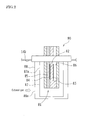
- the A/F sensor 80 shown in FIG. 2 is a layered sensor that outputs signals in accordance with the oxygen concentration in the exhaust gas, and includes a sensor element 81, gas-permeable covers 87, 88, and the like.
- the sensor element 81 is disposed inside the covers 87, 88.
- a large number of small pores 87a, 88a through which exhaust gas can travel are formed in the covers 87, 88, respectively.
- the sensor element 81 is composed of a plate-shaped solid electrolyte layer (for example, made of zirconia) 82, an atmosphere-side electrode (for example, a platinum electrode) 83 formed on one surface of the solid electrolyte layer 82, an exhaust-side electrode (for example, a platinum electrode) 84 formed on the other surface of the solid electrolyte layer 82, a diffusion layer (for example, a porous ceramic) 85, and the like.
- a plate-shaped solid electrolyte layer for example, made of zirconia
- an atmosphere-side electrode for example, a platinum electrode
- an exhaust-side electrode for example, a platinum electrode
- a diffusion layer for example, a porous ceramic
- the atmosphere-side electrode 83 of the sensor element 81 is disposed inside an atmospheric duct 86.
- the inside of the atmospheric duct 86 is open to the atmosphere, and air that has flowed into the atmospheric duct 86 comes in contact with the atmosphere-side electrode 83.
- a surface of the exhaust-side electrode 84 is covered with the diffusion layer 85, and part of the exhaust gas flowing in the exhaust pipe 14b travels inside the diffusion layer 85 and comes in contact with the exhaust-side electrode 84.
- the A/F sensor 80 having such a configuration, when a predetermined voltage is applied across the atmosphere-side electrode 83 and the exhaust-side electrode 84 of the sensor element 81, an output current (sensor current) is generated in accordance with the oxygen concentration in the exhaust gas in the A/F sensor 80 due to this voltage application.
- the sensor current of the A/F sensor 80 shows characteristics that the leaner the air-fuel ratio of the exhaust gas is, the greater the sensor current, and in contrast, the richer the air-fuel ratio of the exhaust gas is, the smaller the sensor current.
- the sensor current of the A/F sensor 80 shows linear characteristics relative to the air-fuel ratio.
- the ECU 100 is provided with a CPU 101, a ROM 102, a RAM 103, a backup RAM 104, an input interface 105, an output interface 106, and the like.
- the CPU 101 executes computational processes based on the various control programs and maps stored in the ROM 102.
- the RAM 103 is a memory that temporarily stores data resulting from computation with the CPU 101 or data that has been input from various sensors and the like.
- the backup RAM 104 is a nonvolatile memory that stores data or the like to be saved when the engine 10 is stopped.
- This CPU 101, ROM 102, RAM 103, and backup RAM 104 are connected to each other via a bus 107, and are also connected to the input interface 105 and the output interface 106 via the bus 107.
- the input interface 105 is connected to the A/F sensor 80, a water temperature sensor 111, an exhaust temperature sensor 112, an air flow meter 113, an intake temperature sensor 114, a crank position sensor 115, a throttle position sensor 116, an accelerator position sensor 117, an outside air temperature sensor 118, and like various sensors.
- the outside air temperature sensor 118 senses the temperature of outside air, and is disposed in a vehicle in a place not affected by heat sources such as the engine 10 and the exhaust system 14.
- the output interface 106 is connected to the first and second switching valves 60, 70, a throttle motor 121 that drives a throttle valve (not shown) attached to the throttle body 13c, injectors 122 that inject fuel into the cylinders of the engine 10, an igniter 123 that adjusts the ignition timing of spark plugs (not shown) attached to the cylinder head 12, and the like.
- the ECU 100 executes various types of control of the engine 10 based on the output of the aforementioned various sensors.
- the ECU 100 executes air-fuel ratio feedback control based on the output of the A/F sensor 80.
- the air-fuel ratio feedback control is to control the injection amount of fuel injected from the injectors 122 into the intake path or the like such that the actual air-fuel ratio of the exhaust gas obtained from the output of the A/F sensor 80 matches the target air-fuel ratio (for example, the theoretical air-fuel ratio).
- the ECU 100 executes the opening/closing control of the first and second switching valves 60, 70 to carry out switching control on the circulation path of the coolant in the coolant circulation circuit 1. Then, the ECU 100 executes the opening/closing control of the second switching valve 70 to carry out flow rate limiting control on the coolant flowing into the exhaust heat recovery unit 40, which will be described below.
- a flow rate limiting means limits the flow rate of the coolant circulating in the exhaust heat recovery unit 40 in the case where a temperature Ta of the sensor element 81 of the A/F sensor 80 is below a predetermined activation temperature T1.
- the extent of opening of the second switching valve 70 which is the aforementioned flow rate control means, is made smaller in the case where the temperature Ta of the sensor element 81 of the A/F sensor 80 is below the predetermined activation temperature T1 than in the case where the temperature Ta is equal to or higher than the activation temperature T1. Accordingly, the temperature of the sensor element 81 of the A/F sensor 80 is promptly increased by limiting the exhaust heat recovery operation performed by the exhaust heat recovery unit 40 to reach the activation temperature T1.
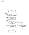
- step ST1 the ECU 100 reads parameters for A/F sensor 80 temperature estimation, and next, in step ST2, estimates the temperature (element temperature) Ta of the sensor element 81 of the A/F sensor 80 based on the parameters read in step ST1.
- a temperature Tw of the coolant, a temperature Tg of the exhaust gas, and a vehicle at-rest time ts are read as parameters for A/F sensor 80 temperature estimation.
- the temperature Tw of the coolant is read from the output signal of the water temperature sensor 111.
- the temperature Tg of the exhaust gas is read from the output signal of the exhaust temperature sensor 112.
- the vehicle at-rest time ts is the time elapsed after a vehicle comes to a stop until it starts moving, and is measured by a timer of the ECU 100. Note that the at-rest time of the engine 10 may be used in place of the vehicle at-rest time ts.
- a temperature estimation map to estimate the temperature Ta of the sensor element 81 of the A/F sensor 80 is preemptively stored in the ROM 102 of the ECU 100.
- This temperature estimation map indicates a relationship, which has been mapped in advance through experimentation, simulation, or the like, between the temperature Ta of the sensor element 81 of the A/F sensor 80 and the parameters for A/F sensor 80 temperature estimation (herein, the temperature Tw of the coolant, the temperature Tg of the exhaust gas, and the vehicle at-rest time ts).
- the temperature Ta of the sensor element 81 of the A/F sensor 80 is estimated based on the parameters read in step ST1 (the temperature Tw of the coolant, the temperature Tg of the exhaust gas, and the vehicle at-rest time ts) with reference to the aforementioned temperature estimation map.
- the temperature Ta of the sensor element 81 of the A/F sensor 80 is estimated so as to be a greater value in the case where the temperature Tw of the coolant is high than in the case where the temperature Tw is low.
- the temperature Ta of the sensor element 81 of the A/F sensor 80 is estimated so as to be a greater value in the case where the temperature Tg of the exhaust gas is high than in the case where the temperature Tg is low.
- the temperature Ta of the sensor element 81 of the A/F sensor 80 is estimated so as to be a greater value in the case where the vehicle at-rest time ts is short than in the case where the vehicle at-rest time ts is long.
- the ECU 100 judges whether the temperature Ta of the sensor element 81 of the A/F sensor 80 estimated in step ST2 is equal to or higher than the activation temperature T1 that has been set in advance.
- the activation temperature T1 is a temperature at which the sensor element 81 of the A/F sensor 80 is sufficiently heated and activated, and specifically, it is set to be a temperature such that the A/F sensor 80 stably outputs a sensor current that is in accordance with the oxygen concentration in the exhaust gas.
- step ST3 In the case of YES in step ST3, or that is, in the case where it is judged that the temperature Ta of the sensor element 81 of the A/F sensor 80 is equal to or higher than the activation temperature T1, the procedure advances to step ST4. On the other hand, in the case of NO in step ST3, or that is, in the case where it is judged that the temperature Ta of the sensor element 81 of the A/F sensor 80 is lower than the activation temperature T1, the procedure advances to step ST5.
- step ST4 the ECU 100 shifts the second switching valve 70 to an open state. Accordingly, the coolant is supplied from the water pump 30 to the exhaust heat recovery unit 40, and the exhaust heat recovery operation by the exhaust heat recovery unit 40 is carried out.
- step ST5 the ECU 100 shifts the second switching valve 70 to a closed state. Accordingly, a supply of the coolant from the water pump 30 to the exhaust heat recovery unit 40 is limited, and the exhaust heat recovery operation by the exhaust heat recovery unit 40 is limited. In this case, a supply of the coolant to the exhaust heat recovery unit 40 is stopped, and the exhaust heat recovery operation by the exhaust heat recovery unit 40 is stopped.
- the flow rate of the coolant that circulates in the exhaust heat recovery unit 40 is limited, and the exhaust heat recovery operation by the exhaust heat recovery unit 40 is limited.
- the flow rate limiting control of the coolant in such an exhaust heat recovery unit 40 in the exhaust heat recovery unit 40, heat exchange between the exhaust gas that flows in the exhaust path of the engine 10 and the coolant that flows into the exhaust heat recovery unit 40 from the introduction pipe H7 is limited, and thus a decrease of the temperature of the exhaust gas resulting from the exhaust heat recovery operation in the exhaust heat recovery unit 40 is suppressed.
- a supply of the coolant to the exhaust heat recovery unit 40 is stopped, a decrease of the temperature of the exhaust gas resulting from the exhaust heat recovery operation in the exhaust heat recovery unit 40 is suppressed, thus making it possible to facilitate the activation of the A/F sensor 80.
- the above-described limitation on the flow rate of the coolant flowing into the exhaust heat recovery unit 40 is lifted when the temperature Ta of the sensor element 81 of the A/F sensor 80 becomes equal to or higher than the activation temperature T1. Accordingly, the coolant is supplied to the exhaust heat recovery unit 40 from the water pump 30, and the exhaust heat recovery operation by the exhaust heat recovery unit 40 is carried out.
- the exhaust heat recovery unit 40 since the exhaust heat recovery unit 40 is disposed in the bypass path that bypasses the engine 10, cooling (or warm-up) of the engine 10 and the exhaust heat recovery operation by the exhaust heat recovery unit 40 can be carried out independently.
- the above-described coolant circulation circuit 1 is an example and can be variously modified as long as it is configured such that the flow rate of the coolant that circulates in the exhaust heat recovery unit 40 can be limited.
- the coolant circulation circuit 1 may be configured so as to be provided with apparatuses other than the radiator 20, the water pump 30, and the exhaust heat recovery unit 40.
- the first switching valve 60 is disposed in the extraction pipe H3 connected downstream of the block-side water jacket 11a, but the first switching valve 60 may be disposed upstream of the block-side water jacket 11a.
- the first switching valve 60 a thermostat that has the same configuration as the thermostat 50 of the foregoing embodiment may be used. Also, as the first switching valve 60, a flow rate regulating valve that regulates, in accordance with the extent of opening of the valve, the flow rate of the coolant that circulates in the block-side water jacket 11a. Note that, in the foregoing embodiment, a supply of the coolant to the block-side water jacket 11a is stopped when the engine 10 is cold, i.e., when the temperature of the coolant is relatively low, but it is also possible to make the flow rate of the coolant supplied to the block-side water jacket 11a small by reducing the extent of opening of the first switching valve 60.
- the second switching valve 70 is disposed in the discharge pipe H8, but the second switching valve 70 may be disposed in the introduction pipe H7.
- the second switching valve 70 a flow rate regulating valve that regulates, in accordance with the extent of opening of the valve, the flow rate of the coolant that circulates in the exhaust heat recovery unit 40.
- the extent of opening of the second switching valve 70 is made smaller than in the case where the temperature Ta is equal to or higher than the activation temperature T1.
- the larger the difference between the temperature Ta of the sensor element 81 of the A/F sensor 80 and the activation temperature T1 the smaller the extent of opening of the second switching valve 70.
- the exhaust heat recovery unit 40 is disposed on the bypass path that bypasses the block-side water jacket 11a and the head-side water jacket 12a, but the exhaust heat recovery unit 40 may be disposed elsewhere.
- a configuration may be possible in which the exhaust heat recovery unit 40 is disposed downstream of the block-side water jacket 11a or downstream of the head-side water jacket 12a.
- the coolant discharged from the water pump 30 is supplied to both the block-side water jacket 11a and the head-side water jacket 12a.
- the present invention is not limited to this configuration, and the coolant discharged from the water pump 30 may be supplied to the head-side water jacket 12a after being circulated in the block-side water jacket 11a.
- an example of the flow rate limiting means is the second switching valve 70.
- the present invention is not limited to this configuration, and the flow rate limiting means can be a water pump capable of regulating the flow rate of the coolant that circulates in the exhaust heat recovery unit 40.
- the discharge amount of the water pump is made smaller than in the case where the temperature Ta is equal to or higher than the activation temperature T 1.
- a configuration in the case of a clutch-operated water pump may be such that a clutch mechanism is interposed between the drive shaft of the water pump and the crankshaft, and with the engine being in a driving state, the water pump is driven when the clutch mechanism is in an engaged state, and the water pump is stopped when the clutch mechanism is in a released state.
- the temperature estimation map for the sensor element 81 of the A/F sensor 80 described in the foregoing embodiment is an example, and the temperature Ta of the sensor element 81 of the A/F sensor 80 may be estimated using other parameters.
- the temperature Ta of the sensor element 81 of the A/F sensor 80 may be estimated based on the temperature Tw of the coolant and the temperature Tg of the exhaust gas.
- the temperature Ta of the sensor element 81 of the A/F sensor 80 may fall below the activation temperature T1.
- the temperature Ta of the sensor element 81 of the A/F sensor 80 is estimated to be a larger value when the outside air temperature is high than when the outside air temperature is low.
- a layered exhaust gas sensor (A/F sensor 80) is used as an example.
- the present invention is not limited thereto, and an exhaust gas sensor having a different structure may be used.
- the A/F sensor 90 shown in FIG. 5 is provided with a sensor element 91, an gas-permeable cover 97, and the like.
- the sensor element 91 is disposed inside the cover 97. Small pores 97a through which the exhaust gas can pass are formed in the cover 97.
- the sensor element 91 has a tubular (cup-shaped) structure with one end being closed.
- the sensor element 91 is composed of a solid electrolyte layer (for example, made of zirconia) 92, an atmosphere-side electrode (for example, a platinum electrode) 93 formed on the inner surface of the solid electrolyte layer 92, an exhaust-side electrode (for example, a platinum electrode) 94 formed on the outside surface of the solid electrolyte layer 92, a porous protective layer (for example, a porous ceramic) 95, and the like.
- an atmospheric chamber 96 that is open to the atmosphere is formed inside the sensor element 91. Atmospheric air that has flowed into this atmospheric chamber 96 comes in contact with the atmosphere-side electrode 93.
- a surface of the exhaust-side electrode 94 is covered with the porous protective layer 95, and some of the exhaust gas flowing in the exhaust pipe 14b travels through the porous protective layer 95 and comes in contact with the exhaust-side electrode 94.
- the cup-shaped A/F sensor 90 shown in FIG. 5 also outputs signals in accordance with the oxygen concentration in the exhaust gas. Specifically, the A/F sensor 90 outputs signals that are increased when the air-fuel ratio of the exhaust gas is leaner and, in contrast, decreased when the air-fuel ratio of the exhaust gas is richer. Then, when the sensor element 91 of the A/F sensor 90 is in an activated state (state in which it is equal to or higher than the activation temperature), the sensor current of the A/F sensor 90 shows linear characteristics relative to the air-fuel ratio.
- an example of the exhaust gas sensor is the A/F sensor 80, but an O 2 sensor may be used as the exhaust gas sensor.
- an O 2 sensor when the sensor element is in an activated state (state in which the temperature is equal to or higher than the activation temperature), the sensor current exhibits characteristics of changing in a stepwise manner in the vicinity of the theoretical air-fuel ratio.
- the present invention is an engine cooling device including a water pump, a radiator, an exhaust heat recovery unit, and a coolant circulation circuit for circulating a coolant in these apparatuses, and is applicable to a device in which an exhaust gas sensor is disposed downstream of the exhaust heat recovery unit in the exhaust path.
Landscapes
- Engineering & Computer Science (AREA)
- Chemical & Material Sciences (AREA)
- Combustion & Propulsion (AREA)
- Mechanical Engineering (AREA)
- General Engineering & Computer Science (AREA)
- Combined Controls Of Internal Combustion Engines (AREA)
- Exhaust Silencers (AREA)
- Exhaust Gas After Treatment (AREA)
Abstract
Description
- The present invention relates to an engine cooling device.
- In an engine (internal combustion engine) mounted in a vehicle or the like, water jackets are each formed in a cylinder head and a cylinder block as coolant paths, and a coolant is circulated in the respective water jackets of the cylinder head and the cylinder block by a water pump. As such an engine cooling device, known is a device in which an exhaust heat recovery unit is disposed in a coolant path (bypass path) that bypasses the respective water jackets of the cylinder head and the cylinder block, and during engine warm-up, no coolant is circulated in the respective water jackets of the cylinder head and the cylinder block, and the coolant is circulated only in the bypass path (for example, see Patent Literature 1). The exhaust heat recovery unit is provided in, for example, the exhaust system of the engine, and is configured so as to be capable of carrying out heat exchange between the exhaust gas flowing in the exhaust path and the coolant flowing in the coolant path.
- Also, air-fuel ratio feedback control is carried out in the engine based on the output of an exhaust gas sensor (for example, A/F sensor, O2 sensor, or the like) disposed in the exhaust path (for example, see Patent Literature 2). In order to stably carry out the air-fuel ratio feedback control, the exhaust gas sensor needs to be in an activated state by being sufficiently heated by the heat of the exhaust gas, and specifically, the temperature of the exhaust gas sensor (the temperature of a sensor element) needs to be equal to or higher than a predetermined activation temperature (for example, see Patent Literature 2 and 3). Patent Literature 3 states that when the temperature of the exhaust path is low, the sensor element of the exhaust gas sensor is heated by a heating means.
-
- [PTL 1]
JP 2009-150266A - [PTL 2]
JP 2009-156052A - [PTL 3]
JP 2007-315855A - [PTL 4]
JP 2010-090828A - Meanwhile, with the engine cooling device described in
Patent Literature 1, because the coolant always circulates in the exhaust heat recovery unit, there is a concern about the following problem. In the case where the exhaust gas sensor as described above is disposed downstream of the exhaust heat recovery unit in the exhaust path, the exhaust gas whose temperature has been decreased by heat exchange in the exhaust heat recovery unit comes in contact with the exhaust gas sensor. Accordingly, during the cold start of the engine or in a similar instance, activation of the exhaust gas sensor is delayed, resulting in a problem in that no air-fuel ratio feedback can be carried out when the temperature of the exhaust gas sensor is below the activation temperature. - The present invention has been achieved in view of such a problem, and an object is to provide an engine cooling device capable of promptly activating an exhaust gas sensor disposed downstream of an exhaust heat recovery unit in the exhaust path.
- In the present invention, a means for solving the above-described problem is configured as follows. That is, the present invention is an engine cooling device including a water pump, a radiator, an exhaust heat recovery unit, and a coolant circulation circuit for circulating a coolant in these apparatuses, the engine cooling device including a flow rate limiting means that limits a flow rate of the coolant that circulates in the exhaust heat recovery unit in a case where a temperature of a sensor element of an exhaust gas sensor that is disposed downstream of the exhaust heat recovery unit in an exhaust path is below a preset activation temperature.
- According to the foregoing configuration, in the case where the temperature of the sensor element of the exhaust gas sensor is below the activation temperature, the flow rate of the coolant that circulates in the exhaust heat recovery unit is limited by the flow rate control means, and the exhaust heat recovery operation by the exhaust heat recovery unit is limited. Therefore, in the exhaust heat recovery unit, heat exchange between the exhaust gas flowing in the exhaust path of the engine and the coolant flowing into the exhaust heat recovery unit is limited, and therefore the temperature decrease of the exhaust gas resulting from the exhaust heat recovery operation in the exhaust heat recovery unit is suppressed. It is thus possible to promptly activate the exhaust gas sensor provided downstream of the exhaust heat recovery unit in the exhaust path. That is, it is possible to promptly raise the temperature of the sensor element of the exhaust gas sensor and reach the activation temperature. Then, it is possible to carry out air-fuel ratio feedback control that is based on the output of the exhaust gas sensor soon after engine start-up.
- In the present invention, it is preferable that the flow rate control means is a valve that is capable of regulating the flow rate of the coolant that circulates in the exhaust heat recovery unit, and makes an extent of opening of the valve smaller in a case where the temperature of the sensor element is below the activation temperature than in a case where the temperature is equal to or higher than the activation temperature.
- According to the foregoing configuration, in the case where the temperature of the sensor element of the exhaust gas sensor is below the activation temperature, the flow rate of the coolant that circulates in the exhaust heat recovery unit is limited by making the extent of opening of the valve small, and thus the exhaust heat recovery operation by the exhaust heat recovery unit is limited. Accordingly, a decrease of the temperature of the exhaust gas resulting from the exhaust heat recovery operation in the exhaust heat recovery unit is suppressed, thus making it possible to promptly activate the exhaust gas sensor provided downstream of the exhaust heat recovery unit in the exhaust path.
- In the present invention, it is preferable that the flow rate control means is a water pump that is capable of regulating the flow rate of the coolant that circulates in the exhaust heat recovery unit, and makes the amount of discharge of the water pump smaller in a case where the temperature of the sensor element is below the activation temperature than in a case where the temperature is equal to or higher than the activation temperature.
- According to the foregoing configuration, in the case where the temperature of the sensor element of the exhaust gas sensor is below the activation temperature, the amount of discharge of the water pump is made small, thus limiting the flow rate of the coolant that circulates in the exhaust heat recovery unit, and limiting the exhaust heat recovery operation performed by the exhaust heat recovery unit. Accordingly, a decrease of the temperature of the exhaust gas resulting from the exhaust heat recovery operation in the exhaust heat recovery unit is suppressed, thus making it possible to promptly activate the exhaust gas sensor provided downstream of the exhaust heat recovery unit in the exhaust path.
- In the present invention, it is preferable that the exhaust heat recovery unit is disposed in a bypass path that bypasses a coolant path provided inside the engine.
- According to the foregoing configuration, cooling (or warm-up) of the engine and the exhaust heat recovery operation by the exhaust heat recovery unit can be carried out independently. For example, even when limitation on the flow rate of the coolant into the exhaust heat recovery unit is lifted, it is possible to limit the flow rate of the coolant into the engine, and it is possible to facilitate engine warm-up while carrying out the exhaust heat recovery operation by the exhaust heat recovery unit.
- In the present invention, it is preferable that coolant paths are each provided inside a cylinder block and a cylinder head of the engine and the coolant paths are disposed in parallel. In this case, it is preferable that a supply of the coolant to the coolant path of the cylinder block is stopped when the engine is cold.
- According to the foregoing configuration, it is possible to facilitate cylinder block warm-up while cooling the cylinder head since a supply of the coolant to the coolant path of the cylinder block is stopped when the engine is cold.
- In the present invention, it is preferable that the flow rate limiting means stops a supply of the coolant to the exhaust heat recovery unit in a case where the temperature of the sensor element is below the activation temperature.
- According to the foregoing configuration, a decrease of the temperature of the exhaust gas resulting from the exhaust heat recovery operation in the exhaust heat recovery unit is suppressed, thus making it possible to facilitate the activation of the exhaust gas sensor provided downstream of the exhaust heat recovery unit in the exhaust path.
- According to the present invention, in the case where the temperature of the sensor element of the exhaust gas sensor is below the activation temperature, the flow rate of the coolant that circulates in the exhaust heat recovery unit is limited by the flow rate control means, and the exhaust heat recovery operation by the exhaust heat recovery unit is limited. Therefore, in the exhaust heat recovery unit, heat exchange between the exhaust gas that flows in the exhaust path of the engine and the coolant that flows into the exhaust heat recovery unit is limited, and thus a decrease of the temperature of the exhaust gas resulting from the exhaust heat recovery operation in the exhaust heat recovery unit is suppressed. This makes it possible to complete at an early stage the activation of the exhaust gas sensor provided downstream of the exhaust heat recovery unit in the exhaust path. That is, it is possible to promptly raise the temperature of the sensor element of the exhaust gas sensor to reach the activation temperature.
-
- [
FIG. 1 ]
FIG. 1 is a schematic diagram showing an engine cooling device and an intake and exhaust system of an engine according to an embodiment. - [
FIG. 2 ]
FIG. 2 is a schematic cross-sectional diagram showing an example of an A/F sensor. - [
FIG. 3 ]
FIG. 3 is a block diagram showing an example of a control system such as an ECU. - [
FIG. 4 ]
FIG. 4 is a flowchart showing an example of flow rate limiting control executed by an ECU on a coolant that flows into an exhaust heat recovery unit. - [
FIG. 5 ]
FIG. 5 is a schematic cross-sectional diagram showing another example of an A/F sensor. - A specific embodiment of the present invention will now be described with reference to the attached drawings.
- Below, an example in which the present invention is applied to an engine cooling device mounted in a vehicle such as an automobile is described.
-
FIG. 1 is a schematic diagram showing an engine cooling device and an intake and exhaust system of an engine according to an embodiment. - The engine cooling device according to an embodiment includes a
coolant circulation circuit 1 for cooling anengine 10 as shown inFIG. 1 . Thecoolant circulation circuit 1 includes, for example, aradiator 20, awater pump 30, an exhaustheat recovery unit 40, and pipes H1 to H8 that connect each of these apparatuses. Also, thecoolant circulation circuit 1 includes athermostat 50 and first andsecond switching valves - In the
coolant circulation circuit 1, alower tank 22 of theradiator 20 and afirst inlet port 51 of thethermostat 50 are connected by a lower pipe H1. Anoutlet port 53 of thethermostat 50 and the suction port of thewater pump 30 are connected by a pump suction pipe H2. - The discharge port of the
water pump 30 is in communication with bothwater jackets engine 10. Specifically, the block-side water jacket 11a is formed inside acylinder block 11 of theengine 10, and a head-side water jacket 12a is formed inside acylinder head 12 of theengine 10. The block-side water jacket 11a and the head-side water jacket 12a are disposed in parallel. The coolant discharged by thewater pump 30 is directly introduced into both the block-side water jacket 11a and the head-side water jacket 12a. - The coolant that has traveled through the block-
side water jacket 11a is extracted out of thecylinder block 11 by an extraction pipe H3. Also, the coolant that has traveled through the head-side water jacket 12a is extracted out of thecylinder head 12 by an extraction pipe H4. The downstream ends of the extraction pipes H3, H4 meet and are connected to an upper pipe H5. Afirst switching valve 60 is provided in the middle of the extraction pipe H3. Also, awater temperature sensor 111 that senses the temperature of the coolant that circulates in thecoolant circulation circuit 1 is provided in the middle of the extraction pipe H4. In this case, the temperature of the coolant sensed by thewater temperature sensor 111 is the temperature of the coolant that has flowed out of the head-side water jacket 12a. - The upper pipe H5 is connected to an
upper tank 21 of theradiator 20. A bypass pipe H6 is connected in the middle of the upper pipe H5 so as to bypass theradiator 20. The downstream end of the bypass pipe H6 is connected to asecond inlet port 52 of thethermostat 50. - Also, the discharge port of the
water pump 30 and anintroduction connecting pipe 41 provided at the introduction port of the exhaustheat recovery unit 40 are connected by an introduction pipe H7. The exhaustheat recovery unit 40 is disposed in parallel with the block-side water jacket 11a and the head-side water jacket 12a. That is, in thecoolant circulation circuit 1, the exhaustheat recovery unit 40 is disposed in a bypass path that bypasses the block-side water jacket 11a and the head-side water jacket 12a, and the coolant discharged from thewater pump 30 is directly introduced into the exhaustheat recovery unit 40. The coolant that has traveled inside the exhaustheat recovery unit 40 is discharged from adischarge connecting pipe 42 to a discharge pipe H8. Thesecond switching valve 70 is provided in the middle of the discharge pipe H8. The downstream end of the discharge pipe H8 is connected to the middle of the upper pipe H5. In this case, the discharge pipe H8 is connected to a portion of the upper pipe H5 that is further upstream than the portion to which the bypass pipe H6 is connected. - Next, the apparatuses provided in the
coolant circulation circuit 1 will now be described briefly. - The
radiator 20 is of a downflow type, and aradiator core 23 is provided between theupper tank 21 and thelower tank 22. The coolant recovered from theengine 10 to theupper tank 21 via the upper pipe H5 undergoes heat exchange with outside air (such as traveling wind, air blown by driving a cooling fan) when flowing down inside theradiator core 23 toward thelower tank 22. This heat exchange dissipates heat to the outside air so as to cool the coolant. - The
water pump 30 is a coolant circulation means for circulating the coolant in thecoolant circulation circuit 1. In this embodiment, thewater pump 30 is driven in response to the rotational driving force of the crankshaft, which is the output shaft of theengine 10. Accordingly, when theengine 10 is in operation, thewater pump 30 is driven, and a coolant circulating operation is carried out in thecoolant circulation circuit 1. - The exhaust
heat recovery unit 40 carries out heat exchange between the exhaust gas that flows in the exhaust path of theengine 10 and the coolant that flows in from the introduction pipe H7, and discharges the heat-exchanged coolant from the discharge pipe H8. A heat exchanging part, which is not shown, is accommodated inside the exhaustheat recovery unit 40, and in this heat exchanging part, the exhaust gas and the coolant undergo heat exchange. A heat exchanging part in which a spiral pipe is accommodated may be usable as the foregoing heat exchanging part, with one end being in communication with theintroduction connecting pipe 41 and the other end being in communication with thedischarge connecting pipe 42. In this case, when the exhaust gas flows inside the exhaustheat recovery unit 40 via anexhaust pipe 14b as theengine 10 operates, the exhaust gas that flows outside the spiral pipe and the coolant that flows inside the spiral pipe undergo heat exchange. As a result, the temperature of the coolant that flows inside the spiral pipe is increased, and exhaust heat is recovered. - Note that exhaust gas whose temperature has been decreased due to heat exchange in the exhaust
heat recovery unit 40 is released into the atmosphere after traveling through acatalyst 14c and a muffler, which is not shown. On the other hand, the coolant whose temperature has been increased due to heat exchange circulates in thecoolant circulation circuit 1 via the discharge pipe H8, and exhaust heat recovered by the coolant is used for heating inside the cabin and for engine warm-up. - The
thermostat 50 switches circulation paths of the coolant in thecoolant circulation circuit 1 according to the temperature of the coolant. Thethermostat 50 is configured such that, for example, a valve is operated by thermowax packed inside that expands/contracts according to the temperature of the coolant. - When the
engine 10 is cold, or that is, in the case where the temperature of the coolant is relatively low, thethermostat 50 is switched to a state in which thefirst inlet port 51 is closed and thesecond inlet port 52 is opened. Accordingly, the flow of the coolant toward thewater pump 30 from thelower tank 22 of theradiator 20 stops, and the coolant flows toward thewater pump 30 from the bypass pipe H6. That is, a coolant circulation operation in which theradiator 20 is not used is carried out in thecoolant circulation circuit 1, and thus anengine 10 warm-up operation is promptly completed. - On the other hand, after the completion of
engine 10 warm-up, or that is, in the case where the temperature of the coolant is increased and the valve opening temperature of thethermostat 50 or a higher temperature is reached, thethermostat 50 is switched to a state in which the first andsecond inlet ports radiator 20 side. That is, the coolant flows toward thewater pump 30 from thelower tank 22 of theradiator 20. In this way, a coolant circulation operation in which the coolant is sent to theradiator 20 is carried out in thecoolant circulation circuit 1, and heat recovered by the coolant is thus released into the atmosphere by theradiator 20. - The
first switching valve 60 can be switched to either an open state in which the coolant can circulate through the extraction pipe H3 (in this case, a completely open state with the extent of opening being 100%) or a closed state in which the coolant cannot circulate through the extraction pipe H3 (in this case, a completely closed state with the extent of opening being 0%). That is, thefirst switching valve 60 can switch states whether a supply of the coolant to the block-side water jacket 11a is made or a supply of the coolant is stopped. In other words, thefirst switching valve 60 can switch states whether cooling the block-side water jacket 11a is carried out or cooling is not carried out. The opening/closing operation of thefirst switching valve 60 is controlled by anECU 100. - Specifically, when the
engine 10 is cold with the temperature of the coolant being relatively low, thefirst switching valve 60 is switched to a closed state, and a supply of the coolant to the block-side water jacket 11a is stopped. Otherwise, the coolant is supplied to the head-side water jacket 12a. Accordingly, the temperature of thecylinder block 11 is promptly increased, while suppressing an excessive increase of the temperature of thecylinder head 12, and friction loss that occurs in various places inside theengine 10 is reduced within a short period of time after engine start-up, thus improving fuel economy. - On the other hand, when the temperature of the coolant is increased and reaches a predetermined switching temperature or a higher temperature, the
first switching valve 60 is switched to an open state. Accordingly, the coolant is supplied to, in addition to the head-side water jacket 12a, to the block-side water jacket 11a. As a result, thecylinder block 11 and thecylinder head 12 are cooled, and thus theengine 10 is maintained at a suitable temperature. - The
second switching valve 70 can be switched to either an open state in which the coolant can circulate through the discharge pipe H8 (in this case, a completely open state with the extent of opening being 100%) or a closed state in which the coolant cannot circulate through the discharge pipe H8 (in this case, a completely closed state with the extent of opening being 0%). That is, thesecond switching valve 70 can switch states whether a supply of the coolant to the exhaustheat recovery unit 40 is made or a supply of the coolant is stopped. In other words, thesecond switching valve 70 can switch states whether the exhaust heat recovery operation by the exhaustheat recovery unit 40 is carried out or the exhaust heat recovery operation is not carried out. - Specifically, when the
second switching valve 70 is switched to an open state, a supply of the coolant to the exhaustheat recovery unit 40 is made, and the exhaust heat recovery operation by the exhaustheat recovery unit 40 is carried out. On the other hand, when thesecond switching valve 70 is switched to a closed state, a supply of the coolant to the exhaustheat recovery unit 40 is stopped, and the exhaust heat recovery operation by the exhaustheat recovery unit 40 is stopped. The opening/closing operation of thesecond switching valve 70 is controlled by anECU 100. An example of the opening/closing control of thesecond switching valve 70 will be described below. - Next, intake and
exhaust systems engine 10 will now be described briefly. - The
engine 10 mixes air supplied from theintake system 13 and fuel supplied from a fuel supply system, which is not shown, in a suitable ratio, and generates power in a vehicle by supplying the air-fuel mixture to the combustion chamber and burning it. Also, theengine 10 releases exhaust gas, which is generated as the air-fuel mixture bums, into the atmosphere from theexhaust system 14. - The
intake system 13 includes anintake pipe 13a. Theintake pipe 13a is provided with anair cleaner 13b, athrottle body 13c, and asurge tank 13d from the upstream side to the downstream side of the flow of intake air. Anintake manifold 13e is connected to the downstream end of theintake pipe 13a, and intake air is divided by theintake manifold 13e and flows into each cylinder of theengine 10. The intake path for introducing intake air into each cylinder of theengine 10 is composed of the internal space of each of these members. - The
exhaust system 14 includes anexhaust manifold 14a attached to theengine 10 and anexhaust pipe 14b connected to theexhaust manifold 14a. The exhaust path for discharging exhaust gas is composed of the internal spaces of theexhaust manifold 14a and theexhaust pipe 14b. - The
exhaust pipe 14b is provided with the above-described exhaustheat recovery unit 40,catalyst 14c, and muffler, which is not shown, and the like from the upstream side to the downstream side of the flow of exhaust air. Also, theexhaust pipe 14b is provided with an A/F sensor (air-fuel ratio sensor) 80 that serves as an exhaust gas sensor, an exhaustgas temperature sensor 112 that senses the temperature of the exhaust gas, and the like. Thecatalyst 14c is composed of a three-way catalyst that collectively converts, for example, carbon monoxide (CO), hydrocarbon (HC), and nitrogen oxide (NOx) into harmless substances. Note that the configuration of theexhaust system 14 is an example and other configurations may be adopted. For example, a configuration may also be adopted in which a so-called start catalyst (S/C) is provided further upstream in the exhaust path than the exhaustheat recovery unit 40. - The A/
F sensor 80 is disposed downstream of the exhaustheat recovery unit 40 in the exhaust path, and senses the air-fuel ratio (A/F) of the exhaust gas introduced into thecatalyst 14c. Here, a specific configuration of the A/F sensor 80 will now be described with reference toFIG. 2 . - The A/
F sensor 80 shown inFIG. 2 is a layered sensor that outputs signals in accordance with the oxygen concentration in the exhaust gas, and includes asensor element 81, gas-permeable covers sensor element 81 is disposed inside thecovers small pores 87a, 88a through which exhaust gas can travel are formed in thecovers - The
sensor element 81 is composed of a plate-shaped solid electrolyte layer (for example, made of zirconia) 82, an atmosphere-side electrode (for example, a platinum electrode) 83 formed on one surface of thesolid electrolyte layer 82, an exhaust-side electrode (for example, a platinum electrode) 84 formed on the other surface of thesolid electrolyte layer 82, a diffusion layer (for example, a porous ceramic) 85, and the like. - The atmosphere-
side electrode 83 of thesensor element 81 is disposed inside anatmospheric duct 86. The inside of theatmospheric duct 86 is open to the atmosphere, and air that has flowed into theatmospheric duct 86 comes in contact with the atmosphere-side electrode 83. On the other hand, a surface of the exhaust-side electrode 84 is covered with thediffusion layer 85, and part of the exhaust gas flowing in theexhaust pipe 14b travels inside thediffusion layer 85 and comes in contact with the exhaust-side electrode 84. - With the A/
F sensor 80 having such a configuration, when a predetermined voltage is applied across the atmosphere-side electrode 83 and the exhaust-side electrode 84 of thesensor element 81, an output current (sensor current) is generated in accordance with the oxygen concentration in the exhaust gas in the A/F sensor 80 due to this voltage application. Specifically, the sensor current of the A/F sensor 80 shows characteristics that the leaner the air-fuel ratio of the exhaust gas is, the greater the sensor current, and in contrast, the richer the air-fuel ratio of the exhaust gas is, the smaller the sensor current. Then, when thesensor element 81 of the A/F sensor 80 is in an activated state (state in which it is equal to or higher than the activation temperature T1, which will be described below), the sensor current of the A/F sensor 80 shows linear characteristics relative to the air-fuel ratio. - Various types of control of the
engine 10 and other members are executed by theECU 100. As shown inFIG. 3 , theECU 100 is provided with aCPU 101, aROM 102, aRAM 103, abackup RAM 104, aninput interface 105, anoutput interface 106, and the like. - In the
ROM 102, various control programs, maps that are referred to when executing such various control programs, and the like are stored. TheCPU 101 executes computational processes based on the various control programs and maps stored in theROM 102. TheRAM 103 is a memory that temporarily stores data resulting from computation with theCPU 101 or data that has been input from various sensors and the like. Thebackup RAM 104 is a nonvolatile memory that stores data or the like to be saved when theengine 10 is stopped. ThisCPU 101,ROM 102,RAM 103, andbackup RAM 104 are connected to each other via abus 107, and are also connected to theinput interface 105 and theoutput interface 106 via thebus 107. - The
input interface 105 is connected to the A/F sensor 80, awater temperature sensor 111, anexhaust temperature sensor 112, anair flow meter 113, anintake temperature sensor 114, a crankposition sensor 115, athrottle position sensor 116, anaccelerator position sensor 117, an outsideair temperature sensor 118, and like various sensors. The outsideair temperature sensor 118 senses the temperature of outside air, and is disposed in a vehicle in a place not affected by heat sources such as theengine 10 and theexhaust system 14. - The
output interface 106 is connected to the first andsecond switching valves throttle motor 121 that drives a throttle valve (not shown) attached to thethrottle body 13c,injectors 122 that inject fuel into the cylinders of theengine 10, anigniter 123 that adjusts the ignition timing of spark plugs (not shown) attached to thecylinder head 12, and the like. - The
ECU 100 executes various types of control of theengine 10 based on the output of the aforementioned various sensors. For example, theECU 100 executes air-fuel ratio feedback control based on the output of the A/F sensor 80. The air-fuel ratio feedback control is to control the injection amount of fuel injected from theinjectors 122 into the intake path or the like such that the actual air-fuel ratio of the exhaust gas obtained from the output of the A/F sensor 80 matches the target air-fuel ratio (for example, the theoretical air-fuel ratio). Also, theECU 100 executes the opening/closing control of the first andsecond switching valves coolant circulation circuit 1. Then, theECU 100 executes the opening/closing control of thesecond switching valve 70 to carry out flow rate limiting control on the coolant flowing into the exhaustheat recovery unit 40, which will be described below. - In this embodiment, a flow rate limiting means is provided that limits the flow rate of the coolant circulating in the exhaust
heat recovery unit 40 in the case where a temperature Ta of thesensor element 81 of the A/F sensor 80 is below a predetermined activation temperature T1. In more detail, the extent of opening of thesecond switching valve 70, which is the aforementioned flow rate control means, is made smaller in the case where the temperature Ta of thesensor element 81 of the A/F sensor 80 is below the predetermined activation temperature T1 than in the case where the temperature Ta is equal to or higher than the activation temperature T1. Accordingly, the temperature of thesensor element 81 of the A/F sensor 80 is promptly increased by limiting the exhaust heat recovery operation performed by the exhaustheat recovery unit 40 to reach the activation temperature T1. An example of this flow rate limiting control on the coolant flowing into the exhaustheat recovery unit 40 will now be described with reference to the flowchart ofFIG. 4 . After theengine 10 is started, the procedure shown in the flowchart ofFIG. 4 is carried out, for example, every few milliseconds or every predetermined crankshaft rotation angle. - First, in step ST1, the
ECU 100 reads parameters for A/F sensor 80 temperature estimation, and next, in step ST2, estimates the temperature (element temperature) Ta of thesensor element 81 of the A/F sensor 80 based on the parameters read in step ST1. - In step ST1, for example, a temperature Tw of the coolant, a temperature Tg of the exhaust gas, and a vehicle at-rest time ts are read as parameters for A/
F sensor 80 temperature estimation. The temperature Tw of the coolant is read from the output signal of thewater temperature sensor 111. The temperature Tg of the exhaust gas is read from the output signal of theexhaust temperature sensor 112. The vehicle at-rest time ts is the time elapsed after a vehicle comes to a stop until it starts moving, and is measured by a timer of theECU 100. Note that the at-rest time of theengine 10 may be used in place of the vehicle at-rest time ts. - A temperature estimation map to estimate the temperature Ta of the
sensor element 81 of the A/F sensor 80 is preemptively stored in theROM 102 of theECU 100. This temperature estimation map indicates a relationship, which has been mapped in advance through experimentation, simulation, or the like, between the temperature Ta of thesensor element 81 of the A/F sensor 80 and the parameters for A/F sensor 80 temperature estimation (herein, the temperature Tw of the coolant, the temperature Tg of the exhaust gas, and the vehicle at-rest time ts). In step ST2, the temperature Ta of thesensor element 81 of the A/F sensor 80 is estimated based on the parameters read in step ST1 (the temperature Tw of the coolant, the temperature Tg of the exhaust gas, and the vehicle at-rest time ts) with reference to the aforementioned temperature estimation map. For example, the temperature Ta of thesensor element 81 of the A/F sensor 80 is estimated so as to be a greater value in the case where the temperature Tw of the coolant is high than in the case where the temperature Tw is low. Also, the temperature Ta of thesensor element 81 of the A/F sensor 80 is estimated so as to be a greater value in the case where the temperature Tg of the exhaust gas is high than in the case where the temperature Tg is low. Also, the temperature Ta of thesensor element 81 of the A/F sensor 80 is estimated so as to be a greater value in the case where the vehicle at-rest time ts is short than in the case where the vehicle at-rest time ts is long. - Next, in step ST3, the
ECU 100 judges whether the temperature Ta of thesensor element 81 of the A/F sensor 80 estimated in step ST2 is equal to or higher than the activation temperature T1 that has been set in advance. The activation temperature T1 is a temperature at which thesensor element 81 of the A/F sensor 80 is sufficiently heated and activated, and specifically, it is set to be a temperature such that the A/F sensor 80 stably outputs a sensor current that is in accordance with the oxygen concentration in the exhaust gas. - In the case of YES in step ST3, or that is, in the case where it is judged that the temperature Ta of the
sensor element 81 of the A/F sensor 80 is equal to or higher than the activation temperature T1, the procedure advances to step ST4. On the other hand, in the case of NO in step ST3, or that is, in the case where it is judged that the temperature Ta of thesensor element 81 of the A/F sensor 80 is lower than the activation temperature T1, the procedure advances to step ST5. - Then, in step ST4, the
ECU 100 shifts thesecond switching valve 70 to an open state. Accordingly, the coolant is supplied from thewater pump 30 to the exhaustheat recovery unit 40, and the exhaust heat recovery operation by the exhaustheat recovery unit 40 is carried out. - On the other hand, in step ST5, the
ECU 100 shifts thesecond switching valve 70 to a closed state. Accordingly, a supply of the coolant from thewater pump 30 to the exhaustheat recovery unit 40 is limited, and the exhaust heat recovery operation by the exhaustheat recovery unit 40 is limited. In this case, a supply of the coolant to the exhaustheat recovery unit 40 is stopped, and the exhaust heat recovery operation by the exhaustheat recovery unit 40 is stopped. - In this embodiment, as described above, in the case where the temperature Ta of the
sensor element 81 of the A/F sensor 80 is below the activation temperature T1, the flow rate of the coolant that circulates in the exhaustheat recovery unit 40 is limited, and the exhaust heat recovery operation by the exhaustheat recovery unit 40 is limited. In accordance with the flow rate limiting control of the coolant in such an exhaustheat recovery unit 40, in the exhaustheat recovery unit 40, heat exchange between the exhaust gas that flows in the exhaust path of theengine 10 and the coolant that flows into the exhaustheat recovery unit 40 from the introduction pipe H7 is limited, and thus a decrease of the temperature of the exhaust gas resulting from the exhaust heat recovery operation in the exhaustheat recovery unit 40 is suppressed. This makes it possible to promptly activate the A/F sensor 80 provided downstream of the exhaustheat recovery unit 40 in the exhaust path. That is, it is possible to promptly raise the temperature of thesensor element 81 of the A/F sensor 80 to reach the activation temperature T1. In this embodiment, since a supply of the coolant to the exhaustheat recovery unit 40 is stopped, a decrease of the temperature of the exhaust gas resulting from the exhaust heat recovery operation in the exhaustheat recovery unit 40 is suppressed, thus making it possible to facilitate the activation of the A/F sensor 80. Then, it is possible to carry out air-fuel ratio feedback control that is based on the output of the A/F sensor 80 soon afterengine 10 start-up. - The above-described limitation on the flow rate of the coolant flowing into the exhaust
heat recovery unit 40 is lifted when the temperature Ta of thesensor element 81 of the A/F sensor 80 becomes equal to or higher than the activation temperature T1. Accordingly, the coolant is supplied to the exhaustheat recovery unit 40 from thewater pump 30, and the exhaust heat recovery operation by the exhaustheat recovery unit 40 is carried out. Here, since the exhaustheat recovery unit 40 is disposed in the bypass path that bypasses theengine 10, cooling (or warm-up) of theengine 10 and the exhaust heat recovery operation by the exhaustheat recovery unit 40 can be carried out independently. - For example, even when limitation on the flow rate of the coolant into the exhaust
heat recovery unit 40 is lifted, it is possible to continuously limit the flow rate of the coolant into the block-side water jacket 11a of theengine 10, and it is possible to facilitate warm-up of thecylinder block 11 while carrying out the exhaust heat recovery operation by the exhaustheat recovery unit 40. - The present invention is not limited only to the above-described embodiment, and all modifications and applications encompassed within the scope of the claims and a range of equivalency therewith are possible.
- (1) The above-described
coolant circulation circuit 1 is an example and can be variously modified as long as it is configured such that the flow rate of the coolant that circulates in the exhaustheat recovery unit 40 can be limited. - For example, the
coolant circulation circuit 1 may be configured so as to be provided with apparatuses other than theradiator 20, thewater pump 30, and the exhaustheat recovery unit 40. - In the foregoing embodiment, the
first switching valve 60 is disposed in the extraction pipe H3 connected downstream of the block-side water jacket 11a, but thefirst switching valve 60 may be disposed upstream of the block-side water jacket 11a. - As the
first switching valve 60, a thermostat that has the same configuration as thethermostat 50 of the foregoing embodiment may be used. Also, as thefirst switching valve 60, a flow rate regulating valve that regulates, in accordance with the extent of opening of the valve, the flow rate of the coolant that circulates in the block-side water jacket 11a. Note that, in the foregoing embodiment, a supply of the coolant to the block-side water jacket 11a is stopped when theengine 10 is cold, i.e., when the temperature of the coolant is relatively low, but it is also possible to make the flow rate of the coolant supplied to the block-side water jacket 11a small by reducing the extent of opening of thefirst switching valve 60. - Also, in the foregoing embodiment, the
second switching valve 70 is disposed in the discharge pipe H8, but thesecond switching valve 70 may be disposed in the introduction pipe H7. - As the
second switching valve 70, a flow rate regulating valve that regulates, in accordance with the extent of opening of the valve, the flow rate of the coolant that circulates in the exhaustheat recovery unit 40. In this case, it is preferable that in the case where the temperature Ta of thesensor element 81 of the A/F sensor 80 is below the activation temperature T1, the extent of opening of thesecond switching valve 70 is made smaller than in the case where the temperature Ta is equal to or higher than the activation temperature T1. Note that, in this case, it is possible to set the extent of opening of thesecond switching valve 70 according to the difference between the temperature Ta of thesensor element 81 of the A/F sensor 80 and the activation temperature T1. Furthermore, it is also possible that the larger the difference between the temperature Ta of thesensor element 81 of the A/F sensor 80 and the activation temperature T1, the smaller the extent of opening of thesecond switching valve 70. - Also, in the foregoing embodiment, the exhaust
heat recovery unit 40 is disposed on the bypass path that bypasses the block-side water jacket 11a and the head-side water jacket 12a, but the exhaustheat recovery unit 40 may be disposed elsewhere. For example, a configuration may be possible in which the exhaustheat recovery unit 40 is disposed downstream of the block-side water jacket 11a or downstream of the head-side water jacket 12a. - Also, in the foregoing embodiment, the coolant discharged from the
water pump 30 is supplied to both the block-side water jacket 11a and the head-side water jacket 12a. However, the present invention is not limited to this configuration, and the coolant discharged from thewater pump 30 may be supplied to the head-side water jacket 12a after being circulated in the block-side water jacket 11a. - (2) In the foregoing embodiment, an example of the flow rate limiting means is the
second switching valve 70. However, the present invention is not limited to this configuration, and the flow rate limiting means can be a water pump capable of regulating the flow rate of the coolant that circulates in the exhaustheat recovery unit 40. In this case, it is preferable that in the case where the temperature Ta of thesensor element 81 of the A/F sensor 80 is below the activation temperature T1, the discharge amount of the water pump is made smaller than in the case where the temperature Ta is equal to or higher than theactivation temperature T 1. - For example, it is possible to use an electrically-operated water pump or a clutch-operated water pump as the flow rate control means. A configuration in the case of a clutch-operated water pump may be such that a clutch mechanism is interposed between the drive shaft of the water pump and the crankshaft, and with the engine being in a driving state, the water pump is driven when the clutch mechanism is in an engaged state, and the water pump is stopped when the clutch mechanism is in a released state.
- (3) The temperature estimation map for the
sensor element 81 of the A/F sensor 80 described in the foregoing embodiment is an example, and the temperature Ta of thesensor element 81 of the A/F sensor 80 may be estimated using other parameters. For example, the temperature Ta of thesensor element 81 of the A/F sensor 80 may be estimated based on the temperature Tw of the coolant and the temperature Tg of the exhaust gas. - It is also possible to use parameters other than the above-described temperature Tw of the coolant, temperature Tg of the exhaust gas, and vehicle at-rest time ts. For example, in cold weather regions, not only during the start-up of the
engine 10, but also during vehicle traveling, the temperature Ta of thesensor element 81 of the A/F sensor 80 may fall below the activation temperature T1. In such a case, it is effective to use, in addition to the aforementioned temperature Tw of the coolant and temperature Tg of the exhaust gas, the outside air temperature sensed by the outsideair temperature sensor 118, as parameters to estimate the temperature Ta of thesensor element 81 of the A/F sensor 80. In this case, the temperature Ta of thesensor element 81 of the A/F sensor 80 is estimated to be a larger value when the outside air temperature is high than when the outside air temperature is low. - (4) In the foregoing embodiment, a layered exhaust gas sensor (A/F sensor 80) is used as an example. However, the present invention is not limited thereto, and an exhaust gas sensor having a different structure may be used. For example, it is also possible to use a cup-shaped exhaust gas sensor (A/F sensor 90) as shown in
FIG. 5 . - The A/
F sensor 90 shown inFIG. 5 is provided with asensor element 91, an gas-permeable cover 97, and the like. Thesensor element 91 is disposed inside thecover 97.Small pores 97a through which the exhaust gas can pass are formed in thecover 97. - The
sensor element 91 has a tubular (cup-shaped) structure with one end being closed. Thesensor element 91 is composed of a solid electrolyte layer (for example, made of zirconia) 92, an atmosphere-side electrode (for example, a platinum electrode) 93 formed on the inner surface of thesolid electrolyte layer 92, an exhaust-side electrode (for example, a platinum electrode) 94 formed on the outside surface of thesolid electrolyte layer 92, a porous protective layer (for example, a porous ceramic) 95, and the like. - Inside the
sensor element 91, anatmospheric chamber 96 that is open to the atmosphere is formed. Atmospheric air that has flowed into thisatmospheric chamber 96 comes in contact with the atmosphere-side electrode 93. On the other hand, a surface of the exhaust-side electrode 94 is covered with the porousprotective layer 95, and some of the exhaust gas flowing in theexhaust pipe 14b travels through the porousprotective layer 95 and comes in contact with the exhaust-side electrode 94. - As with the layered A/
F sensor 80 shown inFIG. 2 , the cup-shaped A/F sensor 90 shown inFIG. 5 also outputs signals in accordance with the oxygen concentration in the exhaust gas. Specifically, the A/F sensor 90 outputs signals that are increased when the air-fuel ratio of the exhaust gas is leaner and, in contrast, decreased when the air-fuel ratio of the exhaust gas is richer. Then, when thesensor element 91 of the A/F sensor 90 is in an activated state (state in which it is equal to or higher than the activation temperature), the sensor current of the A/F sensor 90 shows linear characteristics relative to the air-fuel ratio. - (5) Also, in the foregoing embodiment, an example of the exhaust gas sensor is the A/
F sensor 80, but an O2 sensor may be used as the exhaust gas sensor. In the case of an O2 sensor, when the sensor element is in an activated state (state in which the temperature is equal to or higher than the activation temperature), the sensor current exhibits characteristics of changing in a stepwise manner in the vicinity of the theoretical air-fuel ratio. - The present invention is an engine cooling device including a water pump, a radiator, an exhaust heat recovery unit, and a coolant circulation circuit for circulating a coolant in these apparatuses, and is applicable to a device in which an exhaust gas sensor is disposed downstream of the exhaust heat recovery unit in the exhaust path.
-
- 1
- Coolant circulation circuit
- 10
- Engine
- 11
- Cylinder block
- 11a
- Block-side water jacket
- 12
- Cylinder head
- 12a
- Head-side water jacket
- 20
- Radiator
- 30
- Water pump
- 40
- Exhaust heat recovery unit
- 70
- Second switching valve (flow rate control means)
- 80
- A/F sensor (exhaust gas sensor)
- 100
- ECU
Claims (7)
- An engine cooling device comprising a water pump, a radiator, an exhaust heat recovery unit, and a coolant circulation circuit for circulating a coolant in these apparatuses,
the engine cooling device comprising a flow rate limiting means that limits a flow rate of the coolant that circulates in the exhaust heat recovery unit in a case where a temperature of a sensor element of an exhaust gas sensor that is disposed downstream of the exhaust heat recovery unit in an exhaust path is below a preset activation temperature. - The engine cooling device according to claim 1, wherein
the flow rate control means is a valve that is capable of regulating the flow rate of the coolant that circulates in the exhaust heat recovery unit, and makes an extent of opening of the valve smaller in a case where the temperature of the sensor element is below the activation temperature than in a case where the temperature is equal to or higher than the activation temperature. - The engine cooling device according to claim 1, wherein
the flow rate control means is a water pump that is capable of regulating the flow rate of the coolant that circulates in the exhaust heat recovery unit, and makes the amount of discharge of the water pump smaller in a case where the temperature of the sensor element is below the activation temperature than in a case where the temperature is equal to or higher than the activation temperature. - The engine cooling device according to any one of claims 1 to 3, wherein
the exhaust heat recovery unit is disposed in a bypass path that bypasses a coolant path provided inside the engine. - The engine cooling device according to any one of claims 1 to 4, wherein
coolant paths are each provided inside a cylinder block and a cylinder head of the engine and the coolant paths are disposed in parallel. - The engine cooling device according to claim 5, wherein
a supply of the coolant to the coolant path of the cylinder block is stopped when the engine is cold. - The engine cooling device according to any one of claims 1 to 6, wherein
the flow rate limiting means stops a supply of the coolant to the exhaust heat recovery unit in a case where the temperature of the sensor element is below the activation temperature.
Applications Claiming Priority (1)
| Application Number | Priority Date | Filing Date | Title |
|---|---|---|---|
| PCT/JP2011/066425 WO2013011573A1 (en) | 2011-07-20 | 2011-07-20 | Engine cooling device |
Publications (3)
| Publication Number | Publication Date |
|---|---|
| EP2735716A1 true EP2735716A1 (en) | 2014-05-28 |
| EP2735716A4 EP2735716A4 (en) | 2015-03-04 |
| EP2735716B1 EP2735716B1 (en) | 2016-07-20 |
Family
ID=47557780
Family Applications (1)
| Application Number | Title | Priority Date | Filing Date |
|---|---|---|---|
| EP11869718.4A Not-in-force EP2735716B1 (en) | 2011-07-20 | 2011-07-20 | Engine cooling device |
Country Status (5)
| Country | Link |
|---|---|
| US (1) | US9297292B2 (en) |
| EP (1) | EP2735716B1 (en) |
| JP (1) | JP5403171B2 (en) |
| CN (1) | CN103080495B (en) |
| WO (1) | WO2013011573A1 (en) |
Families Citing this family (12)
| Publication number | Priority date | Publication date | Assignee | Title |
|---|---|---|---|---|
| GB2519167A (en) * | 2013-10-14 | 2015-04-15 | Gm Global Tech Operations Inc | Cooling system for an internal combustion engine |
| SE1351555A1 (en) * | 2013-12-20 | 2014-12-09 | Scania Cv Ab | Cooling arrangement for cooling at least one cylinder of a single-combustion engine |
| WO2015177930A1 (en) * | 2014-05-23 | 2015-11-26 | 日産自動車株式会社 | Cooling circuit for internal combustion engine |
| US9382829B2 (en) | 2014-10-21 | 2016-07-05 | Toyota Motor Engineering & Manufacturing North America, Inc. | Bypass exhaust pathway to allow gases to bypass the start catalyst of a vehicle |
| JP6225931B2 (en) * | 2015-02-20 | 2017-11-08 | トヨタ自動車株式会社 | Cooling device for internal combustion engine |
| JP6449077B2 (en) * | 2015-03-27 | 2019-01-09 | 愛三工業株式会社 | Intake air temperature control device for vehicle engine |
| DE102016215310A1 (en) * | 2016-08-17 | 2018-02-22 | Bayerische Motoren Werke Aktiengesellschaft | Method for cooling a reciprocating engine, computer program product and engine |
| US10677545B2 (en) * | 2016-10-12 | 2020-06-09 | Ford Global Technologies, Llc | Method of flowing coolant through exhaust heat recovery system after engine shutoff |
| KR102324760B1 (en) * | 2017-05-18 | 2021-11-10 | 현대자동차주식회사 | Temperature management method for hybrid vehicle |
| US10428713B2 (en) | 2017-09-07 | 2019-10-01 | Denso International America, Inc. | Systems and methods for exhaust heat recovery and heat storage |
| JP2019163732A (en) * | 2018-03-20 | 2019-09-26 | トヨタ自動車株式会社 | Engine cooling device |
| CN113062793B (en) * | 2021-03-31 | 2022-06-03 | 贵州电子科技职业学院 | Water return pipeline structure of automobile radiator |
Family Cites Families (31)
| Publication number | Priority date | Publication date | Assignee | Title |
|---|---|---|---|---|
| DE1476350A1 (en) * | 1965-07-31 | 1969-07-31 | Daimler Benz Ag | Piston internal combustion engine with a cooling water circuit generated by a water pump |
| JPH0629551B2 (en) * | 1986-05-21 | 1994-04-20 | 株式会社日本自動車部品総合研究所 | Exhaust heat recovery device for internal combustion engine |
| DE3937314A1 (en) * | 1988-11-25 | 1990-05-31 | Volkswagen Ag | Engine with exhaust converter - has outer exhaust cooling pipe supplied from engine dependent on exhaust temp. |
| JPH0742596A (en) * | 1993-07-31 | 1995-02-10 | Suzuki Motor Corp | Air-fuel ratio controller |
| CN2268783Y (en) * | 1995-03-10 | 1997-11-26 | 应∴ | Heater for automotive engine coolant |
| US5901553A (en) * | 1995-03-29 | 1999-05-11 | Ford Global Technologies, Inc. | Method and system for estimating temperature of a heated exhaust gas oxygen sensor in an exhaust system having a variable length pipe |
| JP3573044B2 (en) * | 2000-02-03 | 2004-10-06 | トヨタ自動車株式会社 | Exhaust gas purification device for internal combustion engine |
| JP4157752B2 (en) * | 2002-11-19 | 2008-10-01 | カルソニックカンセイ株式会社 | Engine exhaust heat recovery device |
| DE10332949A1 (en) * | 2003-07-19 | 2005-02-10 | Daimlerchrysler Ag | Device for cooling and preheating |
| DE10332947A1 (en) * | 2003-07-19 | 2005-02-03 | Daimlerchrysler Ag | Internal combustion engine for a motor vehicle |
| FR2873779B1 (en) * | 2004-07-27 | 2008-04-04 | Peugeot Citroen Automobiles Sa | VALVE AND DEVICE FOR HYDRAULIC REGULATION COMPRISING SUCH A VALVE |
| JP4457869B2 (en) * | 2004-11-25 | 2010-04-28 | トヨタ自動車株式会社 | Abnormality detection device for exhaust heat recovery system |
| JP2007016718A (en) * | 2005-07-08 | 2007-01-25 | Toyota Motor Corp | Engine cooling system |
| JP2007046469A (en) | 2005-08-05 | 2007-02-22 | Denso Corp | Waste heat recovery device |
| CN200982960Y (en) * | 2006-03-03 | 2007-11-28 | 孙实庆 | Composite catalyst oxygen sensor device for vehicle |
| BRPI0709424B1 (en) * | 2006-03-28 | 2018-07-03 | Stoneridge, Inc. | TEMPERATURE SENSOR |
| JP4325641B2 (en) * | 2006-05-24 | 2009-09-02 | トヨタ自動車株式会社 | Air-fuel ratio sensor control device |
| US20090050480A1 (en) * | 2007-08-23 | 2009-02-26 | Robert Bosch Gmbh | Exhaust gas sensor |
| JP4998247B2 (en) | 2007-12-19 | 2012-08-15 | トヨタ自動車株式会社 | Cooling water control device for internal combustion engine |
| JP4883000B2 (en) * | 2007-12-25 | 2012-02-22 | トヨタ自動車株式会社 | Air-fuel ratio control device for internal combustion engine |
| DE102008008495A1 (en) * | 2008-02-11 | 2009-08-13 | Pierburg Gmbh | Method for controlling a motor vehicle internal combustion engine arrangement |
| JP4656193B2 (en) * | 2008-06-17 | 2011-03-23 | 株式会社デンソー | Catalyst warm-up controller |
| FR2932845B1 (en) * | 2008-06-24 | 2011-04-22 | Peugeot Citroen Automobiles Sa | METHOD AND DEVICE FOR COOLING A THERMAL MOTOR |
| JP4883324B2 (en) * | 2008-10-09 | 2012-02-22 | 株式会社デンソー | Vehicle heat exchange system |
| JP5381323B2 (en) * | 2009-05-22 | 2014-01-08 | トヨタ自動車株式会社 | Waste heat recovery device |
| JP5304450B2 (en) * | 2009-06-03 | 2013-10-02 | トヨタ自動車株式会社 | Internal combustion engine warm-up device |
| JP2011001876A (en) * | 2009-06-18 | 2011-01-06 | Nissan Motor Co Ltd | Exhaust control device of internal combustion engine |
| DE102010042290A1 (en) * | 2009-10-12 | 2011-08-25 | DENSO CORPORATION, Aichi-pref. | Emissions control system with a heat recovery device |
| JP4998537B2 (en) * | 2009-10-15 | 2012-08-15 | トヨタ自動車株式会社 | Vehicle cooling device |
| JP5384396B2 (en) * | 2010-02-15 | 2014-01-08 | 株式会社デンソー | Engine waste heat control device |
| JP5218526B2 (en) * | 2010-11-11 | 2013-06-26 | トヨタ自動車株式会社 | Water temperature sensor abnormality determination device |
-
2011
- 2011-07-20 JP JP2012552166A patent/JP5403171B2/en not_active Expired - Fee Related
- 2011-07-20 US US13/881,902 patent/US9297292B2/en not_active Expired - Fee Related
- 2011-07-20 CN CN201180040196.1A patent/CN103080495B/en not_active Expired - Fee Related
- 2011-07-20 EP EP11869718.4A patent/EP2735716B1/en not_active Not-in-force
- 2011-07-20 WO PCT/JP2011/066425 patent/WO2013011573A1/en not_active Ceased
Also Published As
| Publication number | Publication date |
|---|---|
| CN103080495B (en) | 2015-06-10 |
| EP2735716A4 (en) | 2015-03-04 |
| US20130213322A1 (en) | 2013-08-22 |
| JP5403171B2 (en) | 2014-01-29 |
| JPWO2013011573A1 (en) | 2015-02-23 |
| CN103080495A (en) | 2013-05-01 |
| WO2013011573A1 (en) | 2013-01-24 |
| US9297292B2 (en) | 2016-03-29 |
| EP2735716B1 (en) | 2016-07-20 |
Similar Documents
| Publication | Publication Date | Title |
|---|---|---|
| EP2735716B1 (en) | Engine cooling device | |
| JP4341689B2 (en) | Secondary air supply device for internal combustion engine | |
| CN107060955B (en) | Method and system for reducing particulate emissions | |
| US8955473B2 (en) | Strategy for engine cold start emission reduction | |
| US9353670B2 (en) | Exhaust gas recirculation system for an internal combustion engine | |
| CN108571379B (en) | Method for operating an internal combustion engine having a turbocharger | |
| JP2018178881A (en) | Egr cooling device | |
| EP2977571B1 (en) | Internal combustion engine and cogeneration device | |
| JP4575934B2 (en) | Exhaust manifold cooling system | |
| EP3009631B1 (en) | Engine control device | |
| US9228464B2 (en) | Method and device for controlling an internal combustion engine | |
| JP4062285B2 (en) | Heat storage system | |
| JP2008232961A (en) | Sensor heating control device, sensor information acquisition device, and engine control system | |
| JP2005264857A (en) | Method and apparatus for warming up an internal combustion engine | |
| US10280859B2 (en) | Control system for internal combustion engine | |
| JP2013087758A (en) | Internal combustion engine cooling control device | |
| GB2582599A (en) | An exhaust system for an internal combustion engine and a method | |
| JP4172296B2 (en) | Control device for internal combustion engine | |
| CN116104616A (en) | Method and system for reducing hydrocarbon emissions from an engine system | |
| JP6061584B2 (en) | Internal combustion engine | |
| JP6355452B2 (en) | Internal combustion engine | |
| JP2024111756A (en) | Exhaust purification equipment | |
| JP2000234548A (en) | Air-fuel ratio sensor heater control device | |
| JP2007016730A (en) | Control device for internal combustion engine | |
| JP2007154818A (en) | Cooling device for internal combustion engine |
Legal Events
| Date | Code | Title | Description |
|---|---|---|---|
| PUAI | Public reference made under article 153(3) epc to a published international application that has entered the european phase |
Free format text: ORIGINAL CODE: 0009012 |
|
| 17P | Request for examination filed |
Effective date: 20140218 |
|
| AK | Designated contracting states |
Kind code of ref document: A1 Designated state(s): AL AT BE BG CH CY CZ DE DK EE ES FI FR GB GR HR HU IE IS IT LI LT LU LV MC MK MT NL NO PL PT RO RS SE SI SK SM TR |
|
| DAX | Request for extension of the european patent (deleted) | ||
| A4 | Supplementary search report drawn up and despatched |
Effective date: 20150204 |
|
| RIC1 | Information provided on ipc code assigned before grant |
Ipc: F01P 7/16 20060101AFI20150129BHEP Ipc: F01N 5/02 20060101ALI20150129BHEP Ipc: F01P 3/02 20060101ALI20150129BHEP |
|
| RIC1 | Information provided on ipc code assigned before grant |
Ipc: F01N 5/02 20060101ALI20151210BHEP Ipc: F01P 3/02 20060101ALI20151210BHEP Ipc: F01P 7/16 20060101AFI20151210BHEP |
|
| GRAP | Despatch of communication of intention to grant a patent |
Free format text: ORIGINAL CODE: EPIDOSNIGR1 |
|
| INTG | Intention to grant announced |
Effective date: 20160203 |
|
| GRAS | Grant fee paid |
Free format text: ORIGINAL CODE: EPIDOSNIGR3 |
|
| GRAA | (expected) grant |
Free format text: ORIGINAL CODE: 0009210 |
|
| AK | Designated contracting states |
Kind code of ref document: B1 Designated state(s): AL AT BE BG CH CY CZ DE DK EE ES FI FR GB GR HR HU IE IS IT LI LT LU LV MC MK MT NL NO PL PT RO RS SE SI SK SM TR |
|
| REG | Reference to a national code |
Ref country code: GB Ref legal event code: FG4D |
|
| REG | Reference to a national code |
Ref country code: CH Ref legal event code: EP |
|
| REG | Reference to a national code |
Ref country code: IE Ref legal event code: FG4D |
|
| REG | Reference to a national code |
Ref country code: AT Ref legal event code: REF Ref document number: 814293 Country of ref document: AT Kind code of ref document: T Effective date: 20160815 |
|
| REG | Reference to a national code |
Ref country code: FR Ref legal event code: PLFP Year of fee payment: 6 |
|
| REG | Reference to a national code |
Ref country code: DE Ref legal event code: R096 Ref document number: 602011028481 Country of ref document: DE |
|
| REG | Reference to a national code |
Ref country code: LT Ref legal event code: MG4D |
|
| REG | Reference to a national code |
Ref country code: NL Ref legal event code: MP Effective date: 20160720 |
|
| REG | Reference to a national code |
Ref country code: AT Ref legal event code: MK05 Ref document number: 814293 Country of ref document: AT Kind code of ref document: T Effective date: 20160720 |
|
| PG25 | Lapsed in a contracting state [announced via postgrant information from national office to epo] |
Ref country code: BE Free format text: LAPSE BECAUSE OF NON-PAYMENT OF DUE FEES Effective date: 20160731 |
|
| PG25 | Lapsed in a contracting state [announced via postgrant information from national office to epo] |
Ref country code: HR Free format text: LAPSE BECAUSE OF FAILURE TO SUBMIT A TRANSLATION OF THE DESCRIPTION OR TO PAY THE FEE WITHIN THE PRESCRIBED TIME-LIMIT Effective date: 20160720 Ref country code: NO Free format text: LAPSE BECAUSE OF FAILURE TO SUBMIT A TRANSLATION OF THE DESCRIPTION OR TO PAY THE FEE WITHIN THE PRESCRIBED TIME-LIMIT Effective date: 20161020 Ref country code: NL Free format text: LAPSE BECAUSE OF FAILURE TO SUBMIT A TRANSLATION OF THE DESCRIPTION OR TO PAY THE FEE WITHIN THE PRESCRIBED TIME-LIMIT Effective date: 20160720 Ref country code: FI Free format text: LAPSE BECAUSE OF FAILURE TO SUBMIT A TRANSLATION OF THE DESCRIPTION OR TO PAY THE FEE WITHIN THE PRESCRIBED TIME-LIMIT Effective date: 20160720 Ref country code: LT Free format text: LAPSE BECAUSE OF FAILURE TO SUBMIT A TRANSLATION OF THE DESCRIPTION OR TO PAY THE FEE WITHIN THE PRESCRIBED TIME-LIMIT Effective date: 20160720 Ref country code: IS Free format text: LAPSE BECAUSE OF FAILURE TO SUBMIT A TRANSLATION OF THE DESCRIPTION OR TO PAY THE FEE WITHIN THE PRESCRIBED TIME-LIMIT Effective date: 20161120 Ref country code: IT Free format text: LAPSE BECAUSE OF FAILURE TO SUBMIT A TRANSLATION OF THE DESCRIPTION OR TO PAY THE FEE WITHIN THE PRESCRIBED TIME-LIMIT Effective date: 20160720 Ref country code: RS Free format text: LAPSE BECAUSE OF FAILURE TO SUBMIT A TRANSLATION OF THE DESCRIPTION OR TO PAY THE FEE WITHIN THE PRESCRIBED TIME-LIMIT Effective date: 20160720 |
|
| PG25 | Lapsed in a contracting state [announced via postgrant information from national office to epo] |
Ref country code: ES Free format text: LAPSE BECAUSE OF FAILURE TO SUBMIT A TRANSLATION OF THE DESCRIPTION OR TO PAY THE FEE WITHIN THE PRESCRIBED TIME-LIMIT Effective date: 20160720 Ref country code: PT Free format text: LAPSE BECAUSE OF FAILURE TO SUBMIT A TRANSLATION OF THE DESCRIPTION OR TO PAY THE FEE WITHIN THE PRESCRIBED TIME-LIMIT Effective date: 20161121 Ref country code: PL Free format text: LAPSE BECAUSE OF FAILURE TO SUBMIT A TRANSLATION OF THE DESCRIPTION OR TO PAY THE FEE WITHIN THE PRESCRIBED TIME-LIMIT Effective date: 20160720 Ref country code: LV Free format text: LAPSE BECAUSE OF FAILURE TO SUBMIT A TRANSLATION OF THE DESCRIPTION OR TO PAY THE FEE WITHIN THE PRESCRIBED TIME-LIMIT Effective date: 20160720 Ref country code: BE Free format text: LAPSE BECAUSE OF FAILURE TO SUBMIT A TRANSLATION OF THE DESCRIPTION OR TO PAY THE FEE WITHIN THE PRESCRIBED TIME-LIMIT Effective date: 20160720 Ref country code: AT Free format text: LAPSE BECAUSE OF FAILURE TO SUBMIT A TRANSLATION OF THE DESCRIPTION OR TO PAY THE FEE WITHIN THE PRESCRIBED TIME-LIMIT Effective date: 20160720 Ref country code: GR Free format text: LAPSE BECAUSE OF FAILURE TO SUBMIT A TRANSLATION OF THE DESCRIPTION OR TO PAY THE FEE WITHIN THE PRESCRIBED TIME-LIMIT Effective date: 20161021 Ref country code: SE Free format text: LAPSE BECAUSE OF FAILURE TO SUBMIT A TRANSLATION OF THE DESCRIPTION OR TO PAY THE FEE WITHIN THE PRESCRIBED TIME-LIMIT Effective date: 20160720 |
|
| REG | Reference to a national code |
Ref country code: CH Ref legal event code: PL |
|
| REG | Reference to a national code |
Ref country code: DE Ref legal event code: R084 Ref document number: 602011028481 Country of ref document: DE |
|
| REG | Reference to a national code |
Ref country code: DE Ref legal event code: R097 Ref document number: 602011028481 Country of ref document: DE |
|
| PG25 | Lapsed in a contracting state [announced via postgrant information from national office to epo] |
Ref country code: LI Free format text: LAPSE BECAUSE OF NON-PAYMENT OF DUE FEES Effective date: 20160731 Ref country code: MC Free format text: LAPSE BECAUSE OF FAILURE TO SUBMIT A TRANSLATION OF THE DESCRIPTION OR TO PAY THE FEE WITHIN THE PRESCRIBED TIME-LIMIT Effective date: 20160720 Ref country code: EE Free format text: LAPSE BECAUSE OF FAILURE TO SUBMIT A TRANSLATION OF THE DESCRIPTION OR TO PAY THE FEE WITHIN THE PRESCRIBED TIME-LIMIT Effective date: 20160720 Ref country code: RO Free format text: LAPSE BECAUSE OF FAILURE TO SUBMIT A TRANSLATION OF THE DESCRIPTION OR TO PAY THE FEE WITHIN THE PRESCRIBED TIME-LIMIT Effective date: 20160720 Ref country code: CH Free format text: LAPSE BECAUSE OF NON-PAYMENT OF DUE FEES Effective date: 20160731 |
|
| REG | Reference to a national code |
Ref country code: IE Ref legal event code: MM4A |
|
| PLBE | No opposition filed within time limit |
Free format text: ORIGINAL CODE: 0009261 |
|
| STAA | Information on the status of an ep patent application or granted ep patent |
Free format text: STATUS: NO OPPOSITION FILED WITHIN TIME LIMIT |
|
| PG25 | Lapsed in a contracting state [announced via postgrant information from national office to epo] |
Ref country code: SM Free format text: LAPSE BECAUSE OF FAILURE TO SUBMIT A TRANSLATION OF THE DESCRIPTION OR TO PAY THE FEE WITHIN THE PRESCRIBED TIME-LIMIT Effective date: 20160720 Ref country code: BG Free format text: LAPSE BECAUSE OF FAILURE TO SUBMIT A TRANSLATION OF THE DESCRIPTION OR TO PAY THE FEE WITHIN THE PRESCRIBED TIME-LIMIT Effective date: 20161020 Ref country code: DK Free format text: LAPSE BECAUSE OF FAILURE TO SUBMIT A TRANSLATION OF THE DESCRIPTION OR TO PAY THE FEE WITHIN THE PRESCRIBED TIME-LIMIT Effective date: 20160720 Ref country code: SK Free format text: LAPSE BECAUSE OF FAILURE TO SUBMIT A TRANSLATION OF THE DESCRIPTION OR TO PAY THE FEE WITHIN THE PRESCRIBED TIME-LIMIT Effective date: 20160720 Ref country code: CZ Free format text: LAPSE BECAUSE OF FAILURE TO SUBMIT A TRANSLATION OF THE DESCRIPTION OR TO PAY THE FEE WITHIN THE PRESCRIBED TIME-LIMIT Effective date: 20160720 |
|
| REG | Reference to a national code |
Ref country code: FR Ref legal event code: PLFP Year of fee payment: 7 |
|
| 26N | No opposition filed |
Effective date: 20170421 |
|
| GBPC | Gb: european patent ceased through non-payment of renewal fee |
Effective date: 20161020 |
|
| PG25 | Lapsed in a contracting state [announced via postgrant information from national office to epo] |
Ref country code: IE Free format text: LAPSE BECAUSE OF NON-PAYMENT OF DUE FEES Effective date: 20160720 Ref country code: GB Free format text: LAPSE BECAUSE OF NON-PAYMENT OF DUE FEES Effective date: 20161020 |
|
| PG25 | Lapsed in a contracting state [announced via postgrant information from national office to epo] |
Ref country code: LU Free format text: LAPSE BECAUSE OF NON-PAYMENT OF DUE FEES Effective date: 20160720 Ref country code: SI Free format text: LAPSE BECAUSE OF FAILURE TO SUBMIT A TRANSLATION OF THE DESCRIPTION OR TO PAY THE FEE WITHIN THE PRESCRIBED TIME-LIMIT Effective date: 20160720 |
|
| PG25 | Lapsed in a contracting state [announced via postgrant information from national office to epo] |
Ref country code: HU Free format text: LAPSE BECAUSE OF FAILURE TO SUBMIT A TRANSLATION OF THE DESCRIPTION OR TO PAY THE FEE WITHIN THE PRESCRIBED TIME-LIMIT; INVALID AB INITIO Effective date: 20110720 Ref country code: CY Free format text: LAPSE BECAUSE OF FAILURE TO SUBMIT A TRANSLATION OF THE DESCRIPTION OR TO PAY THE FEE WITHIN THE PRESCRIBED TIME-LIMIT Effective date: 20160720 |
|
| REG | Reference to a national code |
Ref country code: FR Ref legal event code: PLFP Year of fee payment: 8 |
|
| PG25 | Lapsed in a contracting state [announced via postgrant information from national office to epo] |
Ref country code: MK Free format text: LAPSE BECAUSE OF FAILURE TO SUBMIT A TRANSLATION OF THE DESCRIPTION OR TO PAY THE FEE WITHIN THE PRESCRIBED TIME-LIMIT Effective date: 20160720 Ref country code: MT Free format text: LAPSE BECAUSE OF NON-PAYMENT OF DUE FEES Effective date: 20160731 |
|
| PG25 | Lapsed in a contracting state [announced via postgrant information from national office to epo] |
Ref country code: AL Free format text: LAPSE BECAUSE OF FAILURE TO SUBMIT A TRANSLATION OF THE DESCRIPTION OR TO PAY THE FEE WITHIN THE PRESCRIBED TIME-LIMIT Effective date: 20160720 Ref country code: TR Free format text: LAPSE BECAUSE OF FAILURE TO SUBMIT A TRANSLATION OF THE DESCRIPTION OR TO PAY THE FEE WITHIN THE PRESCRIBED TIME-LIMIT Effective date: 20160720 |
|
| PGFP | Annual fee paid to national office [announced via postgrant information from national office to epo] |
Ref country code: FR Payment date: 20210611 Year of fee payment: 11 |
|
| PGFP | Annual fee paid to national office [announced via postgrant information from national office to epo] |
Ref country code: DE Payment date: 20210622 Year of fee payment: 11 |
|
| REG | Reference to a national code |
Ref country code: DE Ref legal event code: R119 Ref document number: 602011028481 Country of ref document: DE |
|
| PG25 | Lapsed in a contracting state [announced via postgrant information from national office to epo] |
Ref country code: FR Free format text: LAPSE BECAUSE OF NON-PAYMENT OF DUE FEES Effective date: 20220731 |
|
| PG25 | Lapsed in a contracting state [announced via postgrant information from national office to epo] |
Ref country code: DE Free format text: LAPSE BECAUSE OF NON-PAYMENT OF DUE FEES Effective date: 20230201 |