EP2735620A1 - Method for producing hot-pressed steel member - Google Patents
Method for producing hot-pressed steel member Download PDFInfo
- Publication number
- EP2735620A1 EP2735620A1 EP20120814192 EP12814192A EP2735620A1 EP 2735620 A1 EP2735620 A1 EP 2735620A1 EP 20120814192 EP20120814192 EP 20120814192 EP 12814192 A EP12814192 A EP 12814192A EP 2735620 A1 EP2735620 A1 EP 2735620A1
- Authority
- EP
- European Patent Office
- Prior art keywords
- forming
- steel sheet
- less
- press forming
- point
- Prior art date
- Legal status (The legal status is an assumption and is not a legal conclusion. Google has not performed a legal analysis and makes no representation as to the accuracy of the status listed.)
- Granted
Links
- 229910000831 Steel Inorganic materials 0.000 title claims abstract description 193
- 239000010959 steel Substances 0.000 title claims abstract description 193
- 238000004519 manufacturing process Methods 0.000 title claims abstract description 42
- 238000001816 cooling Methods 0.000 claims abstract description 52
- 238000010438 heat treatment Methods 0.000 claims abstract description 50
- 238000000034 method Methods 0.000 claims abstract description 38
- 230000009466 transformation Effects 0.000 claims abstract description 19
- XEEYBQQBJWHFJM-UHFFFAOYSA-N Iron Chemical compound [Fe] XEEYBQQBJWHFJM-UHFFFAOYSA-N 0.000 claims abstract description 16
- 239000000203 mixture Substances 0.000 claims abstract description 14
- 239000000126 substance Substances 0.000 claims abstract description 11
- 239000012535 impurity Substances 0.000 claims abstract description 9
- 229910052742 iron Inorganic materials 0.000 claims abstract description 8
- 230000000717 retained effect Effects 0.000 claims description 27
- 229910001566 austenite Inorganic materials 0.000 claims description 12
- 230000003111 delayed effect Effects 0.000 abstract description 15
- 238000007731 hot pressing Methods 0.000 abstract 1
- 238000002474 experimental method Methods 0.000 description 42
- 238000012360 testing method Methods 0.000 description 39
- 239000000463 material Substances 0.000 description 34
- 238000010586 diagram Methods 0.000 description 28
- 238000006073 displacement reaction Methods 0.000 description 25
- 238000005452 bending Methods 0.000 description 22
- 238000004080 punching Methods 0.000 description 18
- 230000000694 effects Effects 0.000 description 17
- 230000008569 process Effects 0.000 description 17
- 229910000734 martensite Inorganic materials 0.000 description 12
- 238000005259 measurement Methods 0.000 description 11
- 230000015556 catabolic process Effects 0.000 description 10
- 238000006731 degradation reaction Methods 0.000 description 10
- 230000015572 biosynthetic process Effects 0.000 description 9
- 229910052802 copper Inorganic materials 0.000 description 8
- 238000011156 evaluation Methods 0.000 description 7
- 230000003014 reinforcing effect Effects 0.000 description 7
- 230000003068 static effect Effects 0.000 description 7
- 229910000859 α-Fe Inorganic materials 0.000 description 7
- 230000006872 improvement Effects 0.000 description 6
- 238000011835 investigation Methods 0.000 description 6
- 229910052759 nickel Inorganic materials 0.000 description 6
- 238000009966 trimming Methods 0.000 description 6
- 238000007373 indentation Methods 0.000 description 5
- 238000010008 shearing Methods 0.000 description 5
- 229910001563 bainite Inorganic materials 0.000 description 4
- 230000003247 decreasing effect Effects 0.000 description 4
- 230000009467 reduction Effects 0.000 description 4
- 238000005482 strain hardening Methods 0.000 description 4
- 238000009864 tensile test Methods 0.000 description 4
- 238000004364 calculation method Methods 0.000 description 3
- 230000008602 contraction Effects 0.000 description 3
- 239000002245 particle Substances 0.000 description 3
- 230000002093 peripheral effect Effects 0.000 description 3
- 229910001209 Low-carbon steel Inorganic materials 0.000 description 2
- 238000002441 X-ray diffraction Methods 0.000 description 2
- 238000013459 approach Methods 0.000 description 2
- 239000011248 coating agent Substances 0.000 description 2
- 238000000576 coating method Methods 0.000 description 2
- 238000005520 cutting process Methods 0.000 description 2
- 230000007547 defect Effects 0.000 description 2
- 229910052748 manganese Inorganic materials 0.000 description 2
- 230000007246 mechanism Effects 0.000 description 2
- 230000001590 oxidative effect Effects 0.000 description 2
- 229910052698 phosphorus Inorganic materials 0.000 description 2
- 230000000171 quenching effect Effects 0.000 description 2
- 238000007670 refining Methods 0.000 description 2
- 238000005070 sampling Methods 0.000 description 2
- 229910052717 sulfur Inorganic materials 0.000 description 2
- 238000005496 tempering Methods 0.000 description 2
- 238000010998 test method Methods 0.000 description 2
- IJGRMHOSHXDMSA-UHFFFAOYSA-N Atomic nitrogen Chemical compound N#N IJGRMHOSHXDMSA-UHFFFAOYSA-N 0.000 description 1
- JOYRKODLDBILNP-UHFFFAOYSA-N Ethyl urethane Chemical compound CCOC(N)=O JOYRKODLDBILNP-UHFFFAOYSA-N 0.000 description 1
- 229910001335 Galvanized steel Inorganic materials 0.000 description 1
- HCHKCACWOHOZIP-UHFFFAOYSA-N Zinc Chemical compound [Zn] HCHKCACWOHOZIP-UHFFFAOYSA-N 0.000 description 1
- 229910045601 alloy Inorganic materials 0.000 description 1
- 239000000956 alloy Substances 0.000 description 1
- 238000005275 alloying Methods 0.000 description 1
- 230000004075 alteration Effects 0.000 description 1
- 238000000137 annealing Methods 0.000 description 1
- 229910052787 antimony Inorganic materials 0.000 description 1
- 229910052785 arsenic Inorganic materials 0.000 description 1
- 229910052799 carbon Inorganic materials 0.000 description 1
- 238000006243 chemical reaction Methods 0.000 description 1
- 229910052804 chromium Inorganic materials 0.000 description 1
- 239000010960 cold rolled steel Substances 0.000 description 1
- 238000005097 cold rolling Methods 0.000 description 1
- 239000000567 combustion gas Substances 0.000 description 1
- 230000000052 comparative effect Effects 0.000 description 1
- 238000009749 continuous casting Methods 0.000 description 1
- 238000012937 correction Methods 0.000 description 1
- 230000007797 corrosion Effects 0.000 description 1
- 238000005260 corrosion Methods 0.000 description 1
- 239000013078 crystal Substances 0.000 description 1
- 229910001873 dinitrogen Inorganic materials 0.000 description 1
- 238000009826 distribution Methods 0.000 description 1
- 238000000605 extraction Methods 0.000 description 1
- 239000008397 galvanized steel Substances 0.000 description 1
- 239000007789 gas Substances 0.000 description 1
- 238000005098 hot rolling Methods 0.000 description 1
- 229910001337 iron nitride Inorganic materials 0.000 description 1
- 239000002184 metal Substances 0.000 description 1
- 229910052751 metal Inorganic materials 0.000 description 1
- 238000012986 modification Methods 0.000 description 1
- 230000004048 modification Effects 0.000 description 1
- 229910052757 nitrogen Inorganic materials 0.000 description 1
- 229910052760 oxygen Inorganic materials 0.000 description 1
- 238000005554 pickling Methods 0.000 description 1
- 238000001556 precipitation Methods 0.000 description 1
- 238000002360 preparation method Methods 0.000 description 1
- 238000012545 processing Methods 0.000 description 1
- 230000000644 propagated effect Effects 0.000 description 1
- 238000010791 quenching Methods 0.000 description 1
- 230000008707 rearrangement Effects 0.000 description 1
- 229920006395 saturated elastomer Polymers 0.000 description 1
- 238000004088 simulation Methods 0.000 description 1
- 238000010583 slow cooling Methods 0.000 description 1
- 239000002436 steel type Substances 0.000 description 1
- 229910052718 tin Inorganic materials 0.000 description 1
- 238000003466 welding Methods 0.000 description 1
- 229910052725 zinc Inorganic materials 0.000 description 1
- 239000011701 zinc Substances 0.000 description 1
Images


Classifications
-
- C—CHEMISTRY; METALLURGY
- C22—METALLURGY; FERROUS OR NON-FERROUS ALLOYS; TREATMENT OF ALLOYS OR NON-FERROUS METALS
- C22C—ALLOYS
- C22C38/00—Ferrous alloys, e.g. steel alloys
- C22C38/001—Ferrous alloys, e.g. steel alloys containing N
-
- C—CHEMISTRY; METALLURGY
- C21—METALLURGY OF IRON
- C21D—MODIFYING THE PHYSICAL STRUCTURE OF FERROUS METALS; GENERAL DEVICES FOR HEAT TREATMENT OF FERROUS OR NON-FERROUS METALS OR ALLOYS; MAKING METAL MALLEABLE, e.g. BY DECARBURISATION OR TEMPERING
- C21D9/00—Heat treatment, e.g. annealing, hardening, quenching or tempering, adapted for particular articles; Furnaces therefor
-
- B—PERFORMING OPERATIONS; TRANSPORTING
- B21—MECHANICAL METAL-WORKING WITHOUT ESSENTIALLY REMOVING MATERIAL; PUNCHING METAL
- B21D—WORKING OR PROCESSING OF SHEET METAL OR METAL TUBES, RODS OR PROFILES WITHOUT ESSENTIALLY REMOVING MATERIAL; PUNCHING METAL
- B21D22/00—Shaping without cutting, by stamping, spinning, or deep-drawing
- B21D22/02—Stamping using rigid devices or tools
- B21D22/022—Stamping using rigid devices or tools by heating the blank or stamping associated with heat treatment
-
- B—PERFORMING OPERATIONS; TRANSPORTING
- B21—MECHANICAL METAL-WORKING WITHOUT ESSENTIALLY REMOVING MATERIAL; PUNCHING METAL
- B21D—WORKING OR PROCESSING OF SHEET METAL OR METAL TUBES, RODS OR PROFILES WITHOUT ESSENTIALLY REMOVING MATERIAL; PUNCHING METAL
- B21D22/00—Shaping without cutting, by stamping, spinning, or deep-drawing
- B21D22/20—Deep-drawing
- B21D22/208—Deep-drawing by heating the blank or deep-drawing associated with heat treatment
-
- C—CHEMISTRY; METALLURGY
- C21—METALLURGY OF IRON
- C21D—MODIFYING THE PHYSICAL STRUCTURE OF FERROUS METALS; GENERAL DEVICES FOR HEAT TREATMENT OF FERROUS OR NON-FERROUS METALS OR ALLOYS; MAKING METAL MALLEABLE, e.g. BY DECARBURISATION OR TEMPERING
- C21D1/00—General methods or devices for heat treatment, e.g. annealing, hardening, quenching or tempering
- C21D1/62—Quenching devices
- C21D1/673—Quenching devices for die quenching
-
- C—CHEMISTRY; METALLURGY
- C21—METALLURGY OF IRON
- C21D—MODIFYING THE PHYSICAL STRUCTURE OF FERROUS METALS; GENERAL DEVICES FOR HEAT TREATMENT OF FERROUS OR NON-FERROUS METALS OR ALLOYS; MAKING METAL MALLEABLE, e.g. BY DECARBURISATION OR TEMPERING
- C21D8/00—Modifying the physical properties by deformation combined with, or followed by, heat treatment
- C21D8/02—Modifying the physical properties by deformation combined with, or followed by, heat treatment during manufacturing of plates or strips
- C21D8/0247—Modifying the physical properties by deformation combined with, or followed by, heat treatment during manufacturing of plates or strips characterised by the heat treatment
-
- C—CHEMISTRY; METALLURGY
- C21—METALLURGY OF IRON
- C21D—MODIFYING THE PHYSICAL STRUCTURE OF FERROUS METALS; GENERAL DEVICES FOR HEAT TREATMENT OF FERROUS OR NON-FERROUS METALS OR ALLOYS; MAKING METAL MALLEABLE, e.g. BY DECARBURISATION OR TEMPERING
- C21D8/00—Modifying the physical properties by deformation combined with, or followed by, heat treatment
- C21D8/02—Modifying the physical properties by deformation combined with, or followed by, heat treatment during manufacturing of plates or strips
- C21D8/04—Modifying the physical properties by deformation combined with, or followed by, heat treatment during manufacturing of plates or strips to produce plates or strips for deep-drawing
- C21D8/0405—Modifying the physical properties by deformation combined with, or followed by, heat treatment during manufacturing of plates or strips to produce plates or strips for deep-drawing of ferrous alloys
-
- C—CHEMISTRY; METALLURGY
- C22—METALLURGY; FERROUS OR NON-FERROUS ALLOYS; TREATMENT OF ALLOYS OR NON-FERROUS METALS
- C22C—ALLOYS
- C22C38/00—Ferrous alloys, e.g. steel alloys
-
- C—CHEMISTRY; METALLURGY
- C22—METALLURGY; FERROUS OR NON-FERROUS ALLOYS; TREATMENT OF ALLOYS OR NON-FERROUS METALS
- C22C—ALLOYS
- C22C38/00—Ferrous alloys, e.g. steel alloys
- C22C38/002—Ferrous alloys, e.g. steel alloys containing In, Mg, or other elements not provided for in one single group C22C38/001 - C22C38/60
-
- C—CHEMISTRY; METALLURGY
- C22—METALLURGY; FERROUS OR NON-FERROUS ALLOYS; TREATMENT OF ALLOYS OR NON-FERROUS METALS
- C22C—ALLOYS
- C22C38/00—Ferrous alloys, e.g. steel alloys
- C22C38/02—Ferrous alloys, e.g. steel alloys containing silicon
-
- C—CHEMISTRY; METALLURGY
- C22—METALLURGY; FERROUS OR NON-FERROUS ALLOYS; TREATMENT OF ALLOYS OR NON-FERROUS METALS
- C22C—ALLOYS
- C22C38/00—Ferrous alloys, e.g. steel alloys
- C22C38/04—Ferrous alloys, e.g. steel alloys containing manganese
-
- C—CHEMISTRY; METALLURGY
- C22—METALLURGY; FERROUS OR NON-FERROUS ALLOYS; TREATMENT OF ALLOYS OR NON-FERROUS METALS
- C22C—ALLOYS
- C22C38/00—Ferrous alloys, e.g. steel alloys
- C22C38/06—Ferrous alloys, e.g. steel alloys containing aluminium
-
- C—CHEMISTRY; METALLURGY
- C22—METALLURGY; FERROUS OR NON-FERROUS ALLOYS; TREATMENT OF ALLOYS OR NON-FERROUS METALS
- C22C—ALLOYS
- C22C38/00—Ferrous alloys, e.g. steel alloys
- C22C38/08—Ferrous alloys, e.g. steel alloys containing nickel
-
- C—CHEMISTRY; METALLURGY
- C22—METALLURGY; FERROUS OR NON-FERROUS ALLOYS; TREATMENT OF ALLOYS OR NON-FERROUS METALS
- C22C—ALLOYS
- C22C38/00—Ferrous alloys, e.g. steel alloys
- C22C38/12—Ferrous alloys, e.g. steel alloys containing tungsten, tantalum, molybdenum, vanadium, or niobium
-
- C—CHEMISTRY; METALLURGY
- C22—METALLURGY; FERROUS OR NON-FERROUS ALLOYS; TREATMENT OF ALLOYS OR NON-FERROUS METALS
- C22C—ALLOYS
- C22C38/00—Ferrous alloys, e.g. steel alloys
- C22C38/14—Ferrous alloys, e.g. steel alloys containing titanium or zirconium
-
- C—CHEMISTRY; METALLURGY
- C22—METALLURGY; FERROUS OR NON-FERROUS ALLOYS; TREATMENT OF ALLOYS OR NON-FERROUS METALS
- C22C—ALLOYS
- C22C38/00—Ferrous alloys, e.g. steel alloys
- C22C38/16—Ferrous alloys, e.g. steel alloys containing copper
-
- C—CHEMISTRY; METALLURGY
- C22—METALLURGY; FERROUS OR NON-FERROUS ALLOYS; TREATMENT OF ALLOYS OR NON-FERROUS METALS
- C22C—ALLOYS
- C22C38/00—Ferrous alloys, e.g. steel alloys
- C22C38/18—Ferrous alloys, e.g. steel alloys containing chromium
-
- C—CHEMISTRY; METALLURGY
- C22—METALLURGY; FERROUS OR NON-FERROUS ALLOYS; TREATMENT OF ALLOYS OR NON-FERROUS METALS
- C22C—ALLOYS
- C22C38/00—Ferrous alloys, e.g. steel alloys
- C22C38/18—Ferrous alloys, e.g. steel alloys containing chromium
- C22C38/28—Ferrous alloys, e.g. steel alloys containing chromium with titanium or zirconium
-
- C—CHEMISTRY; METALLURGY
- C22—METALLURGY; FERROUS OR NON-FERROUS ALLOYS; TREATMENT OF ALLOYS OR NON-FERROUS METALS
- C22C—ALLOYS
- C22C38/00—Ferrous alloys, e.g. steel alloys
- C22C38/18—Ferrous alloys, e.g. steel alloys containing chromium
- C22C38/30—Ferrous alloys, e.g. steel alloys containing chromium with cobalt
-
- C—CHEMISTRY; METALLURGY
- C22—METALLURGY; FERROUS OR NON-FERROUS ALLOYS; TREATMENT OF ALLOYS OR NON-FERROUS METALS
- C22C—ALLOYS
- C22C38/00—Ferrous alloys, e.g. steel alloys
- C22C38/18—Ferrous alloys, e.g. steel alloys containing chromium
- C22C38/32—Ferrous alloys, e.g. steel alloys containing chromium with boron
-
- C—CHEMISTRY; METALLURGY
- C22—METALLURGY; FERROUS OR NON-FERROUS ALLOYS; TREATMENT OF ALLOYS OR NON-FERROUS METALS
- C22C—ALLOYS
- C22C38/00—Ferrous alloys, e.g. steel alloys
- C22C38/18—Ferrous alloys, e.g. steel alloys containing chromium
- C22C38/34—Ferrous alloys, e.g. steel alloys containing chromium with more than 1.5% by weight of silicon
-
- C—CHEMISTRY; METALLURGY
- C22—METALLURGY; FERROUS OR NON-FERROUS ALLOYS; TREATMENT OF ALLOYS OR NON-FERROUS METALS
- C22C—ALLOYS
- C22C38/00—Ferrous alloys, e.g. steel alloys
- C22C38/18—Ferrous alloys, e.g. steel alloys containing chromium
- C22C38/38—Ferrous alloys, e.g. steel alloys containing chromium with more than 1.5% by weight of manganese
-
- C—CHEMISTRY; METALLURGY
- C22—METALLURGY; FERROUS OR NON-FERROUS ALLOYS; TREATMENT OF ALLOYS OR NON-FERROUS METALS
- C22C—ALLOYS
- C22C38/00—Ferrous alloys, e.g. steel alloys
- C22C38/18—Ferrous alloys, e.g. steel alloys containing chromium
- C22C38/40—Ferrous alloys, e.g. steel alloys containing chromium with nickel
- C22C38/42—Ferrous alloys, e.g. steel alloys containing chromium with nickel with copper
-
- C—CHEMISTRY; METALLURGY
- C22—METALLURGY; FERROUS OR NON-FERROUS ALLOYS; TREATMENT OF ALLOYS OR NON-FERROUS METALS
- C22C—ALLOYS
- C22C38/00—Ferrous alloys, e.g. steel alloys
- C22C38/18—Ferrous alloys, e.g. steel alloys containing chromium
- C22C38/40—Ferrous alloys, e.g. steel alloys containing chromium with nickel
- C22C38/50—Ferrous alloys, e.g. steel alloys containing chromium with nickel with titanium or zirconium
-
- C—CHEMISTRY; METALLURGY
- C22—METALLURGY; FERROUS OR NON-FERROUS ALLOYS; TREATMENT OF ALLOYS OR NON-FERROUS METALS
- C22C—ALLOYS
- C22C38/00—Ferrous alloys, e.g. steel alloys
- C22C38/18—Ferrous alloys, e.g. steel alloys containing chromium
- C22C38/40—Ferrous alloys, e.g. steel alloys containing chromium with nickel
- C22C38/54—Ferrous alloys, e.g. steel alloys containing chromium with nickel with boron
-
- C—CHEMISTRY; METALLURGY
- C22—METALLURGY; FERROUS OR NON-FERROUS ALLOYS; TREATMENT OF ALLOYS OR NON-FERROUS METALS
- C22C—ALLOYS
- C22C38/00—Ferrous alloys, e.g. steel alloys
- C22C38/18—Ferrous alloys, e.g. steel alloys containing chromium
- C22C38/40—Ferrous alloys, e.g. steel alloys containing chromium with nickel
- C22C38/58—Ferrous alloys, e.g. steel alloys containing chromium with nickel with more than 1.5% by weight of manganese
-
- C—CHEMISTRY; METALLURGY
- C21—METALLURGY OF IRON
- C21D—MODIFYING THE PHYSICAL STRUCTURE OF FERROUS METALS; GENERAL DEVICES FOR HEAT TREATMENT OF FERROUS OR NON-FERROUS METALS OR ALLOYS; MAKING METAL MALLEABLE, e.g. BY DECARBURISATION OR TEMPERING
- C21D2211/00—Microstructure comprising significant phases
- C21D2211/002—Bainite
-
- C—CHEMISTRY; METALLURGY
- C21—METALLURGY OF IRON
- C21D—MODIFYING THE PHYSICAL STRUCTURE OF FERROUS METALS; GENERAL DEVICES FOR HEAT TREATMENT OF FERROUS OR NON-FERROUS METALS OR ALLOYS; MAKING METAL MALLEABLE, e.g. BY DECARBURISATION OR TEMPERING
- C21D2211/00—Microstructure comprising significant phases
- C21D2211/008—Martensite
Definitions
- the present invention generally relates to a method of manufacturing a hot-press-formed steel member, in which a steel sheet (hereinafter, also referred to as "blank”) as a material of the member is heated to an austenite transformation point (Ac 3 transformation point) or higher, and is then hot press formed (forming) in a field of manufacturing a formed article of sheet steel mainly used for automotive bodies, and particularly relates to a method of manufacturing a steel member that exhibits high strength and particularly has excellent ductility.
- a steel sheet hereinafter, also referred to as "blank”
- Ac 3 transformation point austenite transformation point
- Automotive steel components have been progressively increased in strength of materials thereof in order to achieve excellent collision safety despite lightweight.
- high workability is required for steel sheets to be used for manufacturing such components.
- a steel sheet having an increased strength particularly a steel sheet having a tensile strength of 980 MPa or more, is subjected to cold working (for example, cold press forming)
- cold working for example, cold press forming
- an increase in forming load of press working and/or extreme degradation in dimension accuracy are disadvantageously caused.
- a measure to solve such problems includes a hot press forming technique in which a steel sheet as a material is press-formed while being heated so that the steel sheet is increased in strength while being formed.
- a steel sheet at high temperature is formed with a tool (a punch and a die), during which the steel sheet is held and cooled at a bottom dead center (of forming), thereby the steel sheet is rapidly cooled through heat removal from the steel sheet to the tool for quenching of the material.
- a forming process achieves a formed article having excellent dimension accuracy and high strength, and reduces a forming load compared with a case where a component in the same strength class is formed in cold working.
- hot press forming is substantially one-time working, and is therefore limited in formable shapes.
- resultant steel member has high strength, it is difficult to perform post working such as cutting and punching on the steel member.
- PTL1 discloses that a steel sheet, to which an element that lowers the Ar 3 point such as Mn, Cu, or Ni is added, is used as a material so that ferrite is not precipitated during press forming, thus allowing two or more times of successive press forming in hot press forming while certain strength of the formed member is secured.
- PTL2 discloses that a hot-rolled steel sheet having a microstructure mainly containing a bainite phase, in which prior austenite grains have an average particle size of 15 ⁇ m or less, is used for forming, and the steel sheet is subjected to predetermined hot press forming to produce a hot press formed member having prior austenite grains having an average particle size of 8 ⁇ m or less, thereby allowing ductility of the member to be secured.
- the blank heating condition includes a heating step of heating to a maximum heating temperature T°C of 675 to 950°C at a heating rate of 10 °C/sec or more, a temperature holding step of holding the maximum heating temperature T°C for (40-T/25) sec or less, and a cooling step of cooling from the maximum heating temperature T°C to a Ms point as a formation temperature of a martensite phase at a cooling rate of 1.0 °C/sec or more, thereby coarsening of austenite can be prevented, and the martensite phase of the member has an average particle size of 5 ⁇ m or less, thus allowing toughness (ductility) of the member to be secured.
- PTL4 discloses that a large amount of hardenable element (Mn, Cr, Cu, or Ni) is added to a material to be hot press formed, which allows holding at a bottom dead center in a press forming tool to be omitted, leading to improvement in productivity.
- Mn, Cr, Cu, or Ni hardenable element
- An object of the present invention which has been made in light of the above-described circumstances, is to establish a technique for manufacturing a hot-press-formed steel member, which exhibits high strength (1100 MPa or more, preferably 1300 MPa or more, and more preferably 1500 MPa or more), excellent tensile elongation (ductility), and excellent bendability, and secures excellent deformation characteristics in collision collapse (crashworthiness) and excellent delayed fracture resistance, by an efficient process having a high degree of freedom of a forming shape.
- a method of manufacturing a hot-press-formed steel member of the present invention that allows the above-described problem to be solved, the steel member being manufactured by heating of a steel sheet having a chemical composition satisfying C: 0.10 to 0.30% (by mass percent, the same holds true for other chemical components), Si: 1.0 to 2.5%, Si+Al: 1.0 to 3.0% in total, and Mn: 1.5 to 3.0%, the remainder consisting of iron and inevitable impurities, and by one or more times of hot press forming of the steel sheet, is characterized in that the heating temperature is an Ac 3 transformation point or higher, start temperature of the hot press forming is the heating temperature or lower and a Ms point or higher, and an average cooling rate from (Ms point-150)°C to 40°C is 5 °C/sec or less.
- finish temperature of final hot press forming may be the Ms point or lower and (Ms point-150)°C or higher.
- the steel sheet for use in the manufacturing method may further contain
- the present invention further includes a hot-press-formed steel member produced by the above-described manufacturing method, the hot-press-formed steel member being characterized by having a steel microstructure that contains 2 vol% or more of retained austenite.
- the present invention further includes a steel sheet to be hot press formed for use in the manufacturing method, the steel sheet being characterized by satisfying C: 0.10 to 0.30%, Si: 1.0 to 2.5%, Si+Al: 1.50 to 3.0% in total, and Mn: 1.5 to 3.0%, the remainder consisting of iron and inevitable impurities.
- the steel sheet may further contain
- the present invention further includes an automotive steel component produced by performing working on the above-described hot-press-formed steel member.
- the steel member subjected to hot press forming exhibits high strength, and has excellent tensile elongation ductility and excellent bendability; hence, the steel component can secure excellent deformation characteristics in collision collapse (crashworthiness), and is thus preferable for automotive high strength steel components. Furthermore, the steel member has excellent delayed fracture resistance. Hence, even if the steel member, which has had high strength through hot press forming, is further subjected to post-working such as punching, the member exhibits excellent delayed fracture resistance at such a worked site.
- the steel member is not held at the bottom dead center unlike hot stamping in the past. Hence, the steel member can be efficiently manufactured. Furthermore, a plurality of times of hot press forming can be performed, leading to a high degree of freedom of a formable shape.
- a forming load of press working can be reduced, and dimension accuracy is excellent compared with cold press forming working, and material damage (work hardening) is small compared with a steel member manufactured by cold press forming.
- ductility (for example, bendability) of a steel component is better than that of a cold-press-formed member.
- the steel member can advantageously absorb a large amount of energy compared with the cold-press-formed member despite having the same strength (i.e., the steel member can be bent to a smaller radius, and has a larger deformation power).
- the steel member is formed in hot working, residual stress after forming can be reduced, and thus delayed fracture is less likely to occur.
- a steel sheet (blank) having a higher Si content than that of a hot stamping steel sheet in the past is prepared, and the steel sheet is heated and subjected to hot press forming one or more times.
- start temperature of the hot press forming is the heating temperature or lower and a Ms point or higher, and an average cooling rate from (Ms point-150)°C to 40°C is 5 °C/sec or less, a high-strength hot-press-formed steel member is obtained, which exhibits high strength, and contains a certain amount or more of retained austenite (retained ⁇ ), and thus exhibits high tensile elongation (ductility) and bendability, secures excellent deformation characteristics in collision collapse (crashworthiness), and secures excellent delayed fracture resistance. Consequently, they have completed the present invention.
- a steel member is manufactured by preparing a steel sheet described later, heating the steel sheet, and performing hot press forming on the steel sheet one or more times.
- the method satisfies the following requirements.
- the steel sheet is heated at an Ac 3 transformation point (austenite transformation point, hereinafter, also referred to as "Ac 3 point") or more, thereby a microstructure described later is readily produced, and thus the steel member has desired characteristics.
- Ac 3 transformation point austenite transformation point, hereinafter, also referred to as "Ac 3 point”
- maximum achieving temperature T is 800°C, i.e., the steel sheet is not heated at a temperature of the Ac 3 transformation point or more.
- Example 1 in PTL3 while experiments are performed with the maximum achieving temperature T being varied between 650 to 1000°C, such experiments are performed at 700°C and 775°C lower than the Ac 3 transformation point in some cases. If the heating temperature is lower than the Ac 3 transformation point in this way, ferrite, etc. remains; hence, even if a cooling rate after heating is controlled, high strength may be extremely difficult to be secured.
- the heating temperature is preferably (Ac 3 point+10)°C or higher. If the heating temperature is extremely high, a microstructure composing the steel member is coarsened, which may cause reduction in ductility and bendability; hence, the upper limit of the heating temperature is about (Ac 3 point+100)°C.
- Heating time of the heating temperature is preferably one minute or more.
- the heating time is preferably 15 min or less in light of suppressing grain growth of austenite, for example. Any heating rate is acceptable up to the Ac 3 transformation point.
- the atmosphere during the heating may be an oxidizing atmosphere, a reducing atmosphere, or a non-oxidizing atmosphere.
- examples of the atmosphere include an air atmosphere, a combustion gas atmosphere, and a nitrogen gas atmosphere.
- the start temperature of the hot press forming is specified to be the heating temperature or lower and the Ms point or higher, thereby allowing working to be easily performed, and allowing a forming load of press working to be sufficiently reduced.
- the start temperature of the hot press forming is preferably (Ms point+30)°C or more, and more preferably (Ms point+50)°C or more.
- start of hot press forming refers to timing at which part of a blank is first contacted to a tool in first forming
- finish of hot press forming refers to timing at which all sites of a formed article are separated from the tool in final forming.
- finish temperature of hot press forming i.e., temperature of the blank at the timing where all sites of a formed article are separated from the tool in final forming
- start temperature of hot press forming i.e., temperature of a blank at the timing where part of the blank is first contacted to a tool in first forming
- finish temperature of hot press forming i.e., temperature of the blank at the timing where all sites of a formed article are separated from the tool in final forming
- the hot press forming may be performed one time or plural times.
- the hot press forming is performed plural times, thereby allowing a member having a complicated shape to be formed, and allowing dimension accuracy to be improved.
- the dimension accuracy is achieved according to the following mechanism.
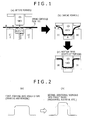
- a blank is contacted to a tool at various sites for different periods, which may cause temperature difference (unevenness) within a formed article.
- a portion A of a blank in Fig. 1 shows a large decrease in temperature (large amount of heat removal to a tool) due to long contact time to the tool
- a portion B of the blank in Fig. 1 shows a small decrease in temperature due to short contact time to the tool.
- Such differences in decrease in temperature cause differences in thermal contraction within a formed article, which induces thermal deformation (plastic deformation), leading to degradation in dimension accuracy of the formed article.
- multistage hot press forming allows correction step with shape constraint to be added, thus allowing dimension accuracy as an issue of multistage hot press forming to be improved. While dimension accuracy is disadvantageously degraded in a hot forming step with productivity-conscious multistage forming, the dimension accuracy is remarkably improved by performing tool release at the Ms point or lower in final hot press forming (including one-time hot press forming) (i.e., by setting finish temperature of final hot press forming to the Ms point or lower). Furthermore, if the contact state to the tool (tool constraint) can be maintained to (Ms point-150) °C, such an effect is further stably exhibited. This is particularly effective for a member produced using a blank having a small thickness of, for example, 1.4 mm or less since degradation in dimension accuracy is large in multistage forming in the case of such a member.
- a forming process includes plural times of forming with one tool, and plural times of forming with a plurality of tools having different shapes, i.e., plural times of forming with tools the shapes of which are different for each of the successive forming operations (steps).
- the multistage forming allows working amount per step for ultimately needed working amount to be reduced, thus allowing forming of a member having a more complicated shape.
- a component such as a rear-side member is three-dimensionally curved, and has a cross-sectional shape (width and height) that varies in a longitudinal direction
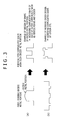
- a component having a complicated shape can be produced by a multistage forming process (with a plurality of steps) as illustrated in Fig. 2 .
- the component can be formed through step distribution, in which, for example, a blank is formed (drown and bent) into a rough shape as illustrated in Fig. 2(a) in a first step, and is then subjected to additional working (such as redrawing and restrike) into a final shape as illustrated by a solid line in Fig. 2(b) in a second step.
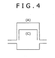
- a resultant shape in each of first and second steps in a multistage forming process is appropriately designed (through appropriate formation of an excess metal portion, appropriate setting of order of working operations, etc.), thereby allowing formation of a remarkably complicated shape as illustrated in of Figs. 3(a) and 3(b) . Formation of such a complicated shape is achieved, which in turn allows higher performance (such as improvement in stiffness and in crashworthiness) of a component and reduction in thickness thereof to be achieved.
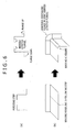
- a component (A) having a reinforcing component (C) for example, a center pillar and a locker
- C reinforcing component
- a sectional shape thereof is less likely to be collapsed (as described in detail in Example 5 later), thus allowing crashworthiness to be improved.
- the component (A) can be formed into a complicated shape, the component (A) itself can be improved in crashworthiness.
- the reinforcing component (C) can be omitted or reduced in thickness, thus achieving lightweight and cost reduction.
- Examples of the multistage forming include stretch-expand forming or flange forming in a second step or later as described below.
- stretch-expand forming is performed in a second step or later of a multistage forming process.
- the stretch-expand shape is added by the stretch-expand forming, thus allowing higher performance (such as improvement in stiffness and in crashworthiness) of a steel component to be achieved.
- flange forming such as flange up, flange down, stretch flange, burring, and shrink flange
- Such flange forming also allows higher performance (such as improvement in stiffness and in crashworthiness) of a steel member to be achieved.
- punching, etc. can be performed.
- piercing (punching) and peripheral trimming (shearing) are performed in the second step or later. Consequently, while piercing and trimming have been performed by laser processing, etc. in different steps in traditional forming with holding at a bottom-dead-center (one-step forming), the piercing and trimming can be performed by press forming, leading to cost reduction.
- peripheral trimming and piercing (punching) may be performed by hot working before forming.
- the finish temperature of hot press forming (finish temperature of final hot press forming, in the case of one-time hot press forming, simply referred to as “finish temperature of hot press forming”) may be the Ms point or higher, or the Ms point or lower and (Ms point-150)°C or higher without limitation.
- the finish temperature of final hot press forming should be the Ms point or higher.
- the finish temperature should be the Ms point or lower and (Ms point-150)°C or higher.
- Press forming is performed in such a temperature region (at timing where martensite transformation occurs), thereby dimension accuracy is remarkably improved.
- the hot press forming is performed plural times, and press forming for tool constraint (however, holding at a bottom dead center is not necessarily required) is performed as final hot press forming at the timing where martensite transformation occurs, thereby dimension accuracy is remarkably improved.
- An embodiment of the hot press forming includes the following modes.
- Any cooling rate is acceptable from the heating temperature to (Ms point-150)°C.
- a material is cooled from the heating temperature to (Ms point-150)°C at an average cooling rate of 2 °C/sec or more (preferably, 5 °C/sec or more).
- martensite can be formed at the Ms point or lower as described below while ferrite, bainite, and the like are substantially not formed, and consequently a member having a high strength of 1100 MPa or more can be readily produced.
- the cooling rate can be controlled by an appropriate combination of time from extraction of a material from a furnace to start of press forming (a cooling rate during conveyance, etc.), contact time to a press forming tool (contact time per forming ⁇ number of times) during hot press forming, in case of plural numbers of press forming, a cooling condition between forming operations (natural cooling, forced wind cooling, etc.), and a cooling condition after finish of press forming (after tool release) (natural cooling, forced wind cooling, etc.).
- a cooling rate at (Ms point-150)°C or higher must be increased, contact time to the press forming tool is effectively lengthened.
- Such cooling conditions can be beforehand estimated by simulation, etc.
- the cooling rate from the heating temperature to the Ms point is preferably 10 °C/sec in order to secure higher strength.
- the average cooling rate from (Ms point-150)°C to 40°C is importantly specified to be 5 °C/sec or less.
- a cooling rate after forming is intentionally decreased, thereby a certain amount or more of retained ⁇ can be secured in a microstructure of a resultant steel member, and consequently desired characteristics (excellent ductility, excellent delayed fracture resistance, and excellent crashworthiness) can be achieved.
- the steel member is not held for a long time at a bottom dead center unlike the traditional hot stamping in order to achieve the above-described average cooling rate. In this way, the steel member is not held for a long time at the bottom dead center.
- the time required for single hot press forming is also shortened, and thus the time required for manufacturing one component is also shortened, leading to an increase in productivity.
- the average cooling rate is preferably 3 °C/sec or less, and more preferably 2 °C/sec or less.
- the lower limit of the average cooling rate is about 0.1 °C/sec in light of productivity, etc.
- the average cooling rate can be achieved by releasing the steel member from a tool after hot press forming, and leaving the steel member for natural cooling, forced wind cooling, or the like.
- the steel member may be held in a warmer for a certain time followed by natural cooling, forced wind cooling, or the like, as necessary.
- a steel sheet containing a certain amount or more of Si is used to prevent such tempering.
- the cooling finish temperature at the above-described average cooling rate may be 40°C.
- the steel member may be slowly cooled to a further low temperature range or room temperature at the average cooling rate of 5 °C/sec or less.
- steel sheets having various compositions are prepared and are "cooled to the Ms point or lower at a predetermined cooling rate".
- a steel type E in Table 6 in PTL3 when a steel sheet having a low Si content is used, high strength as shown in Table 7 is possibly not shown except by rapidly cooling the steel sheet to a low temperature region considerably lower than the Ms point. That is, in Example 6 in PTL3, a steel sheet having any of the compositions is "cooled to the Ms point or lower at a predetermined cooling rate", and thus a high-strength member is produced.
- the steel sheet is rapidly cooled to a low temperature region considerably lower than the Ms point, and therefore the average cooling rate from (Ms point-150)°C to 40°C is possibly not 5 °C/sec or less unlike the present invention. Furthermore, in PTL3, the steel sheet is rapidly cooled to the low temperature region as described above. As a result, retained ⁇ is possibly not sufficiently secured.
- the final-forming finish temperature may be difficult to be lowered to the Ms point or lower without holding at a bottom dead center even if the number of times of press forming is increased.
- a tool structure as illustrated in Fig. 9 is used, thereby contact time of a blank (material) to the tool is increased without holding at a bottom dead center, thus allowing the final-forming finish temperature to be controlled to the Ms point or lower.
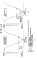
- Fig. 10(I) illustrates one cycle of forming with a traditional tool (including no elastic body)
- Fig. 10(II) illustrates one cycle of forming with the tool (including an elastic body)) of Fig. 9 .
- contact of the tool to the blank (material) starts at the point (a), and forming is performed in a period from the point (a) to the point (d) (in this period, although the pad in Fig. 9 contracts, the elastic body is not deformed (does not expand and contract) (a state of Fig. 9(A) ).
- the pad in Fig. 9 completely contracts, and deformation (contraction) of the elastic body starts (a state of Fig. 9(B) ).
- deformation (contraction) of the elastic body proceeds.
- the elastic body completely contracts (a state of Fig. 9(C) ).
- the elastic body is provided in the upper part of the tool, the elastic body may be provided in a lower part thereof.
- deformation of the elastic body desirably starts after the upper and lower tools of the tool match with each other, even if the deformation of the elastic body starts before such matching, forming finish temperature can be controlled.
- this tool structure may be used only in a particular step in multistage forming.
- Strength of a steel member is primarily determined by C content.
- the C content must be 0.10% or more in order to achieve high strength by the manufacturing method.
- the C content is preferably 0.15% or more, and more preferably 0.17% or more.
- the upper limit of the C content is not limited. However, in consideration of characteristics (such as weldability and toughness) other than strength of the resultant member, the upper limit of the C content is 0.30% or less. The upper limit is preferably 0.25% or less.
- the Si content is preferably 1.1% or more, and more preferably 1.5% or more. Excessive Si content results in degradation in toughness, etc. or formation of an internal oxide layer due to Si during heating of the blank, causing degradation in weldability and conversion treatment performance of the member. Hence, the Si content is 2.5% or less.
- the Si content is preferably 2.0% or less, and more preferably 1.8% or less.
- Si and Al are contained 1.0% or more (preferably 1.50% or more) in total. However, if amounts of such elements are each excessive, the effect is saturated. Hence, Si+Al is 3.0% or less, and preferably 2.5% or less in total.
- Mn is an element useful for improving hardenability of a steel sheet and for reducing variations in hardness of the steel sheet after forming. Mn must be contained 1.5% or more to exhibit such effects. The Mn content is preferably 1.8% or more. However, an excessive Mn content of more than 3.0% results in saturation of the effects, and causes an increase in cost. The Mn content is preferably 2.8% or less.
- the composition of the steel of the present invention is as described above, and the remainder thereof consists of iron and inevitable impurities (for example, P, S, N, O, As, Sb, and Sn).
- P and S are each preferably decreased to 0.02% or less in light of securing weldability, etc.
- the N content is excessive, degradation in toughness after hot forming or degradation in weldability is caused; hence, the N content is preferably controlled to be 0.01% or less.
- O causes a surface defect; hence, the O content is preferably controlled to be 0.001% or less.
- Cr is an element useful for improving hardenability of a steel sheet. Variations in hardness of a formed article can be promisingly reduced by containing the element. Cr is preferably contained 0.01% or more to exhibit such an effect. More preferably, Cr is contained 0.1% or more. However, excessive Cr content results in saturation of such an effect, and causes cost rise. Hence, the upper limit of Cr content is preferably 1%.
- Ti is an element that fixes N and secures the quenching effect by B. Furthermore, Ti also exhibits an effect of refining a microstructure, which advantageously facilitates formation of retained ⁇ during cooling in a temperature range of (Ms point-150)°C or lower.
- Ti is preferably contained 0.02% or more to exhibit such effects. More preferably, Ti is contained 0.03% or more.
- the Ti content is preferably 0.10% or less. More preferably, the Ti content is 0.07% or less.
- B is an element that improves hardenability of a steel sheet.
- B is preferably contained 0.0003% or more to exhibit such an effect. More preferably, B is contained 0.0015% or more, and further preferably 0.0020% or more.
- the B content is preferably controlled to be 0.005% or less, more preferably 0.0040% or less, and further preferably 0.0035% or less.
- Ni and Cu are each an element useful for improvement in corrosion resistance and further improvement in delayed fracture resistance of a formed article.
- Ni and Cu are preferably contained 0.01% or more in total to exhibit such effects.
- Ni and Cu are more preferably contained 0.1% or more in total.
- excessive total content of Ni and Cu causes occurrence of a surface defect during manufacturing of a steel sheet.
- the total content of Ni and Cu is preferably 0.5% or less. More preferably, the total content of Ni and Cu is 0.3% or less.
- Mo is an element useful for improving hardenability of a steel sheet. Variations in hardness of a formed article can be promisingly reduced by containing the element. Mo is preferably contained 0.01% or more to exhibit such an effect. More preferably, Mo is contained 0.1% or more. However, excessive Mo content results in saturation of such an effect, and causes cost rise. Hence, the upper limit of Mo content is preferably 1%.
- Nb exhibits an effect of refining a microstructure, which advantageously facilitates formation of retained ⁇ during cooling in a temperature range of (Ms point-150)°C or lower.
- Nb is preferably contained 0.005% or more to exhibit such an effect. More preferably, Nb is contained 0.01% or more. Excessive Nb content results in saturation of such an effect, and causes cost rise. Hence, the upper limit of Nb content is preferably 0.05%.
- the blank satisfying the above-described composition may be manufactured by any of typical methods without limitation, the method including in continuous casting, heating, hot rolling, pickling, and cold rolling, and including annealing as necessary.
- Further usable steel sheet includes a coated steel sheet (such as a galvanized steel sheet) corresponding to the resultant hot-rolled steel sheet or cold-rolled steel sheet being further subjected to coating (such as zinc-containing coating), and a hot-dip galvannealed steel sheet, etc. produced by alloying the coated layer.
- the hot-press-formed steel member produced by the method of the present invention has the same chemical composition as that of the used blank, and has a steel microstructure containing retained austenite (retained ⁇ ) by 2 vol% or more of the entire microstructure.
- the steel member produced by the manufacturing method of the present invention contains 2 vol% or more of retained ⁇ , and is therefore excellent in tensile elongation ductility, crashworthiness, and delayed fracture resistance.
- the amount of the retained ⁇ is preferably 3 vol% or more, and more preferably 5 vol% or more.
- the remainder other than the retained ⁇ substantially consists of low-temperature transformation phases (such as martensite, tempered martensite, bainite, and bainitic ferrite).
- low-temperature transformation phases such as martensite, tempered martensite, bainite, and bainitic ferrite.
- the resultant steel member is subjected to cutting such as trimming and piercing, so that, for example, an automotive steel component can be produced.
- the resultant steel member has excellent delayed fracture resistance; hence, even if the steel member is subjected to such working, delayed fracture may not occur in the worked portion.
- the steel member may be used as the automotive steel component directly or after being subjected to the above-described working, the automotive steel component including, for example, an impact bar, a bumper, a reinforce, and a center pillar.
- a steel sheet (a blank with a size having a thickness of 1.4 mm, a width of 190.5 mm, and a length of 400 mm) having a chemical composition (the remainder consisting of iron and inevitable impurities) shown in Table 1 was prepared.
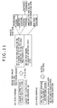
- the steel sheet was then subjected to press forming working, i.e., hot press forming or cold press forming, according to the procedure illustrated in Fig. 11 .
- press forming working i.e., hot press forming or cold press forming, according to the procedure illustrated in Fig. 11 .
- heating temperature in the hot press forming was 930°C
- start temperature of the hot press forming was 800 to 700°C.
- Experiment Nos. 4 to 9 and 11 to 18 in Table 2 described later Experiment No. 18 was subjected to forced wing cooling after press forming, and Experiment No.
- press forming bending (form) forming using a leading pad
- press forming machine 400-ton mechanical press
- a spring having a force of about 1 ton was used as a pressure source for the leading pad.
- Fig. 1 illustrates a forming process, in which 1 represents a punch, 2 represents a die, 3 represents a leading pad, 4 represents a steel sheet (blank), and 5 represents a pin (spring-contained float pin).
- each spring-contained pin 5 was disposed on the tool (the die 2 and the leading pad 3), and the blank 4 removed from a furnace was temporarily set on the pins 5 in order to avoid contact of the blank 4 to the tool (the die 2 and the leading pad 3) to the utmost.
- Fig. 1(b) illustrates a state during the forming, in which the punch 1 is being lowered.
- Fig. 1(c) illustrates a state where the punch 1 is lowered to the bottom dead center (lower limit position).
- forming was performed using the steel sheet 4 at normal temperature without holding at the bottom dead center.
- the steel member was fabricated in the same way as Experiment No. 5 in Table 2 (the number of times of press forming: one) except that the number of times of press forming was three, and press forming was finished at the Ms point or lower and (Ms point-150)°C or higher.
- Experiment No. 9 in Table 2 the steel member was fabricated in the same way as Experiment No. 5 in Table 2 (the number of times of press forming: one) except that the number of times of press forming was two.
- Fig. 13 illustrates one cycle of the forming, and "time required for single press forming" and “holding at bottom dead center” shown in Table 2 correspond to time required for single press forming and holding time at bottom dead center, respectively, illustrated in Fig. 13 .
- thermocouples that were buried in the center of a top board and the center of a longitudinal wall of the resultant steel member. Temperatures measured at such two points were substantially equal to each other.
- a cooling rate from the heating temperature to the calculated (Ms point-150)°C and a cooling rate from the (Ms point-150)°C to 40°C were each read from the measured temperature history, and the average cooling rate shown in Table 2 was calculated.
- the final tool release temperature shown in Table 2 was determined from temperature indicated by each thermocouple and a corresponding tool position. In this Example, this final tool release temperature corresponds to the finish temperature of the final hot press forming.
- the steel members (formed members) produced in the above way were used for investigation of steel microstructures, and were subjected to tensile tests and evaluation of ductility (bendability) as described below.
- the amount of retained austenite (retained ⁇ ) in a steel microstructure was measured according to the following procedure.
- a specimen 15 mm long and 15 mm wide was sampled from a top board of the steel member.
- the specimen was ground to one quarter of the thickness thereof and was then chemically polished, and was then subjected to measurement by X-ray diffraction (the measurement condition is as follows).
- Table 2 shows results of the measurement.
- a JIS-5 specimen was cut out as a tensile test specimen from part of the formed component (steel member). Subsequently, yield strength (YS), tensile strength (TS), and elongation (El) were measured by a procedure specified in JIS Z 2241 with a strain rate of 10 mm/min using an AG-IS 250kN autograph tensile tester from Shimadzu Corporation. Table 2 shows results of the measurement.
- a steel strip 150 mm long and 30 mm wide was cut out as a bending test specimen from a longitudinal wall of the formed component (steel member).
- the specimen was subjected to preliminary bending as illustrated in Fig. 17(a) .
- a first end of the specimen was fixed by pinching a fixing tool and a lower tool, and a second curved end thereof was pinched by an upper tool and the lower tool, and then a load was applied from the upper side of the upper tool until the specimen was broken.
- a load, at a point where a bent portion of the specimen was broken, was determined, and the equivalent bending radius (R) was determined by formula (1).
- Table 3 shows results of the bending test.
- Fig. 18 illustrates an exemplary relationship between the equivalent bending radius (R) and the load.
- R H - 2 ⁇ t / 2 wherein
- the dimension accuracy was evaluated through obtaining the maximum opening displacement as described below.
- Fig. 19 is a diagram illustrating measurement points of opening displacement of each resultant steel member.
- the opening displacement was determined at A, B, and C.
- values of (W-47.2) in cross sections at A, B, and C were obtained, and a largest value among such values was determined as the maximum opening displacement.
- Table 4 shows results of the measurement. Table 4 Experiment No.
- the material of the blank symbol B in Table 1 was formed into an arc shape. At this time, while the time required for single press forming, the number of times of press forming, and indentation depth were each varied, influence of such variations on dimension accuracy of the resultant steel member was investigated.
- the material (1.4 mm thick and 110 mm square) of the blank symbol B in Table 1 was heated to 930°C, and was then formed into an arc shape after being waited for 10 sec on float pins in a forming unit (tool) illustrated in Fig. 21 .
- a forming unit illustrated in Fig. 21 .
- time required for single press forming, the number of times of press forming, and indentation depth were varied as shown in Table 5 while the material was not held at the bottom dead center, thereby the final-forming finish temperature was varied.
- the forming was performed with the forming unit (tool) set in a crank press in the 780 kN class.
- R the radius of curvature of the arc shape after forming (tool release) was determined as R1.
- Forming which allowed excellent dimension accuracy to be secured, was separately performed with holding at the bottom dead center (13 sec) and the final-forming finish temperature of 60°C (forming under a reference condition) to produce an article formed under the reference condition, and R of the article was determined as R2.
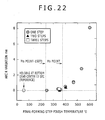
- R1-R2 was determined as "arc R variation", and was used as an evaluation index for dimension accuracy. Table 5 further shows results of such investigation.
- Fig. 22 illustrates a relationship between the final-forming finish temperature and the arc R variation obtained through rearrangement of the results in Table 5.
- Fig. 22 reveals that if tool release is performed at the final-forming finish temperature of the Ms point or lower, dimension accuracy is extremely improved regardless of the number of times of press forming (one to three steps), thus achieving dimension accuracy similar to that obtained in a traditional technique with holding at a bottom dead center.
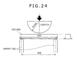
- a three-point bend test (collapse test) was performed (an indenter had a semicircular column shape and a length in a paper depth direction of 150 mm).
- this collapse test two types of tests, i.e., a static test with a test speed of 1 mm/sec and a dynamic test with a test speed of 32 km/hr, were performed.
- a static test with a test speed of 1 mm/sec
- a dynamic test with a test speed of 32 km/hr
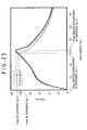
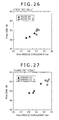
- the horizontal axis i.e., "displacement” represents indentation depth assuming that the indentation depth is 0 when the indenter is contacted to the specimen. Similar measurement was performed for the dynamic test. In addition, the maximum load (Pmax) and displacement at the maximum load (Pmax-induced displacement) were determined for each of the tests. Figs. 26 and 27 each show results of the tests.
- Fig. 26 is a diagram illustrating a relationship between the maximum load (Pmax) and displacement at the maximum load (Pmax-induced displacement) in the static test.
- Fig. 27 is a diagram illustrating a relationship between the maximum load (Pmax) and displacement at the maximum load (Pmax-induced displacement) in the dynamic test.
- Figs. 26 and 27 reveal that the steel member of the present invention (Experiment No. 8) is high in maximum load and is large in displacement at the maximum load compared with Experiment No. 1 (comparative example) in both of the static test and the dynamic test.
- Fig. 28 illustrates exemplary top photographs (after the static test) of the specimens after the collapse test in Experiment No. 1 and Experiment No. 8.
- Experiment No. 8 shows a stable collapse position, namely, shows a stabilized buckling mode, i.e., stable crashworthiness.
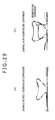
- Fig. 29 includes cross sectional diagrams each illustrating a deformation image (a section at the center of the length of 400 mm in a longitudinal direction) during collapse of a steel member (with a backing plate).
- Fig. 29(a) illustrates a case with a reinforcing component
- Fig. 29(b) illustrates a case without a reinforcing component.
- a sectional shape is less likely to be collapsed (Sectional height is less likely to be decreased.
- the material (1.4 mm thick and 100 mm square) of the blank symbol B in Table 1 was heated to 930°C. Then, using a test unit (tool) of Fig. 31 , the material was waited on the tool until temperature reached a predetermined forming start temperature (room temperature, 200°C, 300°C, 400°C, 500°C, 600°C, or 700°C). At the predetermined forming start temperature, as illustrated in Fig. 31 , stretch-expand forming (blank holder pressure: 2 tons) was performed with a coining punch 10 mm in diameter.
- a predetermined forming start temperature room temperature, 200°C, 300°C, 400°C, 500°C, 600°C, or 700°C.
- stretch-expand forming blade holder pressure: 2 tons
- Fig. 32 illustrates results of such determination in a form of a relationship between the forming start temperature and the maximum forming height.
- Fig. 32 reveals that the maximum forming height is 6 to 7 mm in a range of the forming start temperature of the Ms point or higher and less than about 400°C, showing excellent stretch-expand forming. This means that excellent stretch-expand formability, which is similar to that in cold press forming of steel in the tensile strength of 440 MPa class as illustrated in Fig. 32 , can be secured.
- Table 6 teaches the following. Specifically, the maximum forming height is 22 mm in a range of the forming start temperature of the Ms point or higher and less than about 400°C, showing excellent stretch flange forming. This means that excellent stretch flange formability, which is similar to or higher than that in cold press forming of steel in the tensile strength of 590 MPa class, can be secured. As a result, as illustrated in Fig. 6(b) , a continuous flange is achieved in a joint portion while such a continuous flange is difficult to be achieved by cold press forming.
- the material (1.4 mm thick and 100 mm square) of the blank symbol B in Table 1 was heated to 930°C. Then, the material was waited on a tool until temperature reached a predetermined punching temperature (room temperature, 200°C, 300°C, 400°C, 500°C, 600°C, or 700°C). At the predetermined punching temperature, shearing (punching) was performed with a punch 10 mm in diameter. In addition, a load (shearing load) in such working was measured. A clearance CL between a die and a punch was set to each of 10% and 20% of the thickness.
- the shearing load was measured at each temperature, and a ratio (%) of such a shearing load to a reference load (a load at similar punching of the material (having a tensile strength of 1518 MPa from Table 2) of the blank symbol D in Table 1) was calculated.
- Fig. 35 illustrates results of such calculation in a form of a relationship between the punching temperature and the ratio with respect to the reference load.
- Fig. 35 further illustrates a load at cold punching of steel in the tensile strength of 590 MPa class and a load at cold punching of mild steel, such types of steel being generally mass-produced by press forming working.
- Fig. 35 reveals that when the punching temperature is the Ms point or higher, punching can be performed at a low load similar to that in cold press forming of a material of which the strength is in a range of a tensile strength of a mild steel level to a tensile strength of 590 MPa class.
Abstract
Description
- The present invention generally relates to a method of manufacturing a hot-press-formed steel member, in which a steel sheet (hereinafter, also referred to as "blank") as a material of the member is heated to an austenite transformation point (Ac3 transformation point) or higher, and is then hot press formed (forming) in a field of manufacturing a formed article of sheet steel mainly used for automotive bodies, and particularly relates to a method of manufacturing a steel member that exhibits high strength and particularly has excellent ductility.
- Automotive steel components have been progressively increased in strength of materials thereof in order to achieve excellent collision safety despite lightweight. In addition, high workability is required for steel sheets to be used for manufacturing such components. However, in the case where a steel sheet having an increased strength, particularly a steel sheet having a tensile strength of 980 MPa or more, is subjected to cold working (for example, cold press forming), an increase in forming load of press working and/or extreme degradation in dimension accuracy are disadvantageously caused.
- A measure to solve such problems includes a hot press forming technique in which a steel sheet as a material is press-formed while being heated so that the steel sheet is increased in strength while being formed. In this measure, a steel sheet at high temperature is formed with a tool (a punch and a die), during which the steel sheet is held and cooled at a bottom dead center (of forming), thereby the steel sheet is rapidly cooled through heat removal from the steel sheet to the tool for quenching of the material. Such a forming process achieves a formed article having excellent dimension accuracy and high strength, and reduces a forming load compared with a case where a component in the same strength class is formed in cold working.
- In such a measure, however, the steel sheet must be held for a certain time at the bottom dead center, which results in long occupation of a press forming machine for manufacturing of one steel member, thus leading to low productivity.
- In addition, hot press forming is substantially one-time working, and is therefore limited in formable shapes. Moreover, since the resultant steel member has high strength, it is difficult to perform post working such as cutting and punching on the steel member.
- Thus, various investigations have been made on hot press forming techniques in order to improve productivity and increase the degree of forming freedom.
- For example, PTL1 discloses that a steel sheet, to which an element that lowers the Ar3 point such as Mn, Cu, or Ni is added, is used as a material so that ferrite is not precipitated during press forming, thus allowing two or more times of successive press forming in hot press forming while certain strength of the formed member is secured.
- PTL2 discloses that a hot-rolled steel sheet having a microstructure mainly containing a bainite phase, in which prior austenite grains have an average particle size of 15 µm or less, is used for forming, and the steel sheet is subjected to predetermined hot press forming to produce a hot press formed member having prior austenite grains having an average particle size of 8 µm or less, thereby allowing ductility of the member to be secured.
- PTL3 discloses that a blank heating condition for hot press forming is set to rapid heating and short holing, in detail, the blank heating condition includes a heating step of heating to a maximum heating temperature T°C of 675 to 950°C at a heating rate of 10 °C/sec or more, a temperature holding step of holding the maximum heating temperature T°C for (40-T/25) sec or less, and a cooling step of cooling from the maximum heating temperature T°C to a Ms point as a formation temperature of a martensite phase at a cooling rate of 1.0 °C/sec or more, thereby coarsening of austenite can be prevented, and the martensite phase of the member has an average particle size of 5 µm or less, thus allowing toughness (ductility) of the member to be secured.
- PTL4 discloses that a large amount of hardenable element (Mn, Cr, Cu, or Ni) is added to a material to be hot press formed, which allows holding at a bottom dead center in a press forming tool to be omitted, leading to improvement in productivity.
- Any of such techniques does not necessarily require holding at the bottom dead center, which promisingly improves productivity, but does not investigate higher ductility, deformation characteristics in collision collapse (hereinafter, the characteristics are also referred to as "crashworthiness"), and delayed fracture resistance as described below.
- Specifically, in PTL1, since the cooling rate is increased to the utmost after completion of press forming, higher ductility is less likely to be achieved. Furthermore, in each of PTL1 and PTL4, a material (blank) contains a large amount of an alloy element to secure strength; hence, ductility is less likely to be secured.
- In addition, when a member is increased in strength, delayed fracture may occur, but any of PTL1 to PTL4 does not focus delayed fracture resistance. Furthermore, when then member is used for an automotive component, crashworthiness must be considered, but none of PTL1 to PTL4 focuses on the crashworthiness.
-
- PTL1: Japanese Unexamined Patent Application Publication No.
2006-212663 - PTL2: Japanese Unexamined Patent Application Publication No.
2010-174280 - PTL3: Japanese Unexamined Patent Application Publication No.
2010-70806 - PTL4: Japanese Unexamined Patent Application Publication No.
2006-213959 - An object of the present invention, which has been made in light of the above-described circumstances, is to establish a technique for manufacturing a hot-press-formed steel member, which exhibits high strength (1100 MPa or more, preferably 1300 MPa or more, and more preferably 1500 MPa or more), excellent tensile elongation (ductility), and excellent bendability, and secures excellent deformation characteristics in collision collapse (crashworthiness) and excellent delayed fracture resistance, by an efficient process having a high degree of freedom of a forming shape.
- A method of manufacturing a hot-press-formed steel member of the present invention that allows the above-described problem to be solved, the steel member being manufactured by heating of a steel sheet having a chemical composition satisfying
C: 0.10 to 0.30% (by mass percent, the same holds true for other chemical components),
Si: 1.0 to 2.5%,
Si+Al: 1.0 to 3.0% in total, and
Mn: 1.5 to 3.0%,
the remainder consisting of iron and inevitable impurities, and by one or more times of hot press forming of the steel sheet, is characterized in that
the heating temperature is an Ac3 transformation point or higher,
start temperature of the hot press forming is the heating temperature or lower and a Ms point or higher, and
an average cooling rate from (Ms point-150)°C to 40°C is 5 °C/sec or less. - In the hot press forming, finish temperature of final hot press forming may be the Ms point or lower and (Ms point-150)°C or higher.
- The steel sheet for use in the manufacturing method may further contain
- (a) Cr: 1% or less (not including 0%),
- (b) Ti: 0.10% or less (not including 0%),
- (c) B: 0.005% or less (not including 0%),
- (d) Ni and/or Cu: 0.5% or less (not including 0%),
- (e) Mo: 1% or less (not including 0%), and
- (f) Nb: 0.05% or less (not including 0%).
- The present invention further includes a hot-press-formed steel member produced by the above-described manufacturing method, the hot-press-formed steel member being characterized by having a steel microstructure that contains 2 vol% or more of retained austenite.
- The present invention further includes a steel sheet to be hot press formed for use in the manufacturing method, the steel sheet being characterized by satisfying
C: 0.10 to 0.30%,
Si: 1.0 to 2.5%,
Si+Al: 1.50 to 3.0% in total, and
Mn: 1.5 to 3.0%,
the remainder consisting of iron and inevitable impurities. - The steel sheet may further contain
- (a) Cr: 1% or less (not including 0%),
- (b) Ti: 0.10% or less (not including 0%),
- (c) B: 0.005% or less (not including 0%),
- (d) Ni and/or Cu: 0.5% or less in total (not including 0%),
- (e) Mo: 1% or less (not including 0%), or
- (f) Nb: 0.05% or less (not including 0%).
- The present invention further includes an automotive steel component produced by performing working on the above-described hot-press-formed steel member.
- According to the present invention, the steel member subjected to hot press forming exhibits high strength, and has excellent tensile elongation ductility and excellent bendability; hence, the steel component can secure excellent deformation characteristics in collision collapse (crashworthiness), and is thus preferable for automotive high strength steel components. Furthermore, the steel member has excellent delayed fracture resistance. Hence, even if the steel member, which has had high strength through hot press forming, is further subjected to post-working such as punching, the member exhibits excellent delayed fracture resistance at such a worked site.
- In addition, the steel member is not held at the bottom dead center unlike hot stamping in the past. Hence, the steel member can be efficiently manufactured. Furthermore, a plurality of times of hot press forming can be performed, leading to a high degree of freedom of a formable shape.
- Furthermore, a forming load of press working can be reduced, and dimension accuracy is excellent compared with cold press forming working, and material damage (work hardening) is small compared with a steel member manufactured by cold press forming. Hence, ductility (for example, bendability) of a steel component is better than that of a cold-press-formed member. When an automotive steel member is deformed to be bent due to collision, the steel member can advantageously absorb a large amount of energy compared with the cold-press-formed member despite having the same strength (i.e., the steel member can be bent to a smaller radius, and has a larger deformation power). In addition, since the steel member is formed in hot working, residual stress after forming can be reduced, and thus delayed fracture is less likely to occur.
-
-
Fig. 1 includes diagrams illustrating press forming (hot press forming or cold press forming) steps in an Example. -
Fig. 2 includes schematic illustrations of a multistage forming process. -
Fig. 3 includes illustrations each illustrating an exemplary multistage forming process. -
Fig. 4 is a cross section diagram of a steel component having a reinforcing component. -
Fig. 5 is a schematic illustration illustrating an example of stretch-expand forming in a multistage forming process. -
Fig. 6 includes schematic illustrations each illustrating an example of flange forming in a multistage forming process. -
Fig. 7 includes schematic illustrations each illustrating an example of piercing or (peripheral) trimming in a multistage forming process. -
Fig. 8 is a schematic illustration of forming of a steel member in the case where a vertical wall of a target shape has a large inclination angle θ. -
Fig. 9 includes schematic illustrations of a tool structure usable in the present invention. -
Fig. 10 includes diagrams each explaining one cycle of forming with a tool. -
Fig. 11 is a diagram illustrating a hot press forming process and a cold press forming process performed in the Example. -
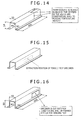
Fig. 12 is a schematic perspective diagram illustrating a shape of a steel member produced in the Example. -
Fig. 13 is a diagram explaining the time required for one step of press forming (hot press forming or cold press forming) in the Example. -
Fig. 14 is a diagram explaining buried positions of thermocouples for measurement of temperature of a steel sheet in the Example. -
Fig. 15 is a diagram illustrating a sampling position of a tensile test specimen from a steel member in the Example. -
Fig. 16 is a diagram illustrating a sampling position of a bending test specimen from a steel member in another Example. -
Fig. 17 includes illustrations of a bending test procedure in the Example. -
Fig. 18 is a diagram illustrating an example of a bending test result (a relationship between an equivalent bending radius (R) and a load) in the Example. -
Fig. 19 is a diagram illustrating measurement points of opening displacement of a steel member in another Example. -
Fig. 20 is a diagram explaining how to determine the opening displacement in the Example. -
Fig. 21 is a schematic illustration of a forming unit (tool) used for evaluation of dimension accuracy in another Example. -
Fig. 22 is a diagram illustrating a relationship between final-forming finish temperature and an arc R variation in the Example. -
Fig. 23 is a schematic perspective diagram of a specimen used in a collapse test in another Example. -
Fig. 24 is a schematic illustration of a procedure of a collapse test (three-point bend test) in the Example. -
Fig. 25 is a diagram illustrating an example of a collapse test result (a load-displacement diagram) in the Example. -
Fig. 26 is a diagram illustrating a collapse test (static test) result (a relationship between Pmax and Pmax-induced displacement) in the Example. -
Fig. 27 is a diagram illustrating a collapse test (dynamic test) result (a relationship between Pmax and Pmax-induced displacement) in the Example. -
Fig. 28 includes photographs of tops of specimens after the collapse test in the Example. -
Fig. 29 includes cross section diagrams illustrating deformation images during collapse of the steel member illustrated inFig. 23 . -
Fig. 30 is a diagram illustrating a relationship between an equivalent bending radius and a maximum load in bending in the Example. -
Fig. 31 is a schematic illustration of a test unit (tool) used for evaluation of stretch-expand formability in another Example. -
Fig. 32 is a diagram illustrating a relationship between (stretch-expand) forming start temperature and maximum forming height (of stretch-expand forming) in the Example. -
Fig. 33 includes schematic illustrations of a test unit (tool) used for evaluation of stretch flange formability in another Example. -
Fig. 34 is a photograph of a stretch-flange-formed component, explaining a position of the largest forming height (Hmax). -
Fig. 35 is a diagram illustrating a relationship between punching temperature and a sharing load (a proportion with respect to a reference load) in another Example. - The inventors have made studies to achieve a member having the above-described characteristics. As a result, as described below, they have got the following findings. In a method of manufacturing a steel member, a steel sheet (blank) having a higher Si content than that of a hot stamping steel sheet in the past is prepared, and the steel sheet is heated and subjected to hot press forming one or more times. In particular, when temperature during the heating (heating temperature) is an Ac3 transformation point or more, start temperature of the hot press forming is the heating temperature or lower and a Ms point or higher, and an average cooling rate from (Ms point-150)°C to 40°C is 5 °C/sec or less, a high-strength hot-press-formed steel member is obtained, which exhibits high strength, and contains a certain amount or more of retained austenite (retained γ), and thus exhibits high tensile elongation (ductility) and bendability, secures excellent deformation characteristics in collision collapse (crashworthiness), and secures excellent delayed fracture resistance. Consequently, they have completed the present invention.
- The reason for specifying the manufacturing condition in the present invention is now described in detail.
- In the manufacturing method of the present invention, a steel member is manufactured by preparing a steel sheet described later, heating the steel sheet, and performing hot press forming on the steel sheet one or more times. The method satisfies the following requirements.
- The steel sheet is heated at an Ac3 transformation point (austenite transformation point, hereinafter, also referred to as "Ac3 point") or more, thereby a microstructure described later is readily produced, and thus the steel member has desired characteristics. In contrast, in any of Examples 2 to 6 in PTL3, while the Ac3 transformation point of a used steel sheet is higher than 800°C, maximum achieving temperature T is 800°C, i.e., the steel sheet is not heated at a temperature of the Ac3 transformation point or more. In Example 1 in PTL3, while experiments are performed with the maximum achieving temperature T being varied between 650 to 1000°C, such experiments are performed at 700°C and 775°C lower than the Ac3 transformation point in some cases. If the heating temperature is lower than the Ac3 transformation point in this way, ferrite, etc. remains; hence, even if a cooling rate after heating is controlled, high strength may be extremely difficult to be secured.
- The heating temperature is preferably (Ac3 point+10)°C or higher. If the heating temperature is extremely high, a microstructure composing the steel member is coarsened, which may cause reduction in ductility and bendability; hence, the upper limit of the heating temperature is about (Ac3 point+100)°C.
- Heating time of the heating temperature is preferably one minute or more. The heating time is preferably 15 min or less in light of suppressing grain growth of austenite, for example. Any heating rate is acceptable up to the Ac3 transformation point.
- The atmosphere during the heating may be an oxidizing atmosphere, a reducing atmosphere, or a non-oxidizing atmosphere. Specifically, examples of the atmosphere include an air atmosphere, a combustion gas atmosphere, and a nitrogen gas atmosphere.
- The start temperature of the hot press forming is specified to be the heating temperature or lower and the Ms point or higher, thereby allowing working to be easily performed, and allowing a forming load of press working to be sufficiently reduced. The start temperature of the hot press forming is preferably (Ms point+30)°C or more, and more preferably (Ms point+50)°C or more.
- In the present invention, start of hot press forming refers to timing at which part of a blank is first contacted to a tool in first forming, and finish of hot press forming refers to timing at which all sites of a formed article are separated from the tool in final forming.
- In the present invention, although the start temperature of hot press forming (i.e., temperature of a blank at the timing where part of the blank is first contacted to a tool in first forming) is specified, finish temperature of hot press forming (i.e., temperature of the blank at the timing where all sites of a formed article are separated from the tool in final forming) is not specified (the finish temperature of hot press forming is described in detail below).
- The hot press forming may be performed one time or plural times. The hot press forming is performed plural times, thereby allowing a member having a complicated shape to be formed, and allowing dimension accuracy to be improved. The dimension accuracy is achieved according to the following mechanism.
- In a press forming process, a blank is contacted to a tool at various sites for different periods, which may cause temperature difference (unevenness) within a formed article. For example, in the case of bending forming as illustrated in
Fig. 1 , a portion A of a blank inFig. 1 shows a large decrease in temperature (large amount of heat removal to a tool) due to long contact time to the tool, while a portion B of the blank inFig. 1 shows a small decrease in temperature due to short contact time to the tool. Such differences in decrease in temperature cause differences in thermal contraction within a formed article, which induces thermal deformation (plastic deformation), leading to degradation in dimension accuracy of the formed article. - In contrast, when multistage forming, i.e., a plurality of times of press forming working are performed at the Ms point or higher, and even if degradation in dimension accuracy occurs in a prior step, since subsequent forming is still performed at high temperature, such degradation in dimension accuracy can be readily corrected. Furthermore, repeated forming eliminates unevenness in temperature depending on sites; hence, degradation in dimension accuracy due to unevenness in temperature is also easily resolved.
- Furthermore, such multistage hot press forming allows correction step with shape constraint to be added, thus allowing dimension accuracy as an issue of multistage hot press forming to be improved. While dimension accuracy is disadvantageously degraded in a hot forming step with productivity-conscious multistage forming, the dimension accuracy is remarkably improved by performing tool release at the Ms point or lower in final hot press forming (including one-time hot press forming) (i.e., by setting finish temperature of final hot press forming to the Ms point or lower). Furthermore, if the contact state to the tool (tool constraint) can be maintained to (Ms point-150) °C, such an effect is further stably exhibited. This is particularly effective for a member produced using a blank having a small thickness of, for example, 1.4 mm or less since degradation in dimension accuracy is large in multistage forming in the case of such a member.
- For plural times of hot press forming, a forming process includes plural times of forming with one tool, and plural times of forming with a plurality of tools having different shapes, i.e., plural times of forming with tools the shapes of which are different for each of the successive forming operations (steps).
- The multistage forming allows working amount per step for ultimately needed working amount to be reduced, thus allowing forming of a member having a more complicated shape.
- For example, while a component such as a rear-side member is
three-dimensionally curved, and has
a cross-sectional shape (width and height) that varies in a longitudinal direction,
such a component is generally difficult to be formed into a final shape in one step. However, the component having a complicated shape can be produced by a multistage forming process (with a plurality of steps) as illustrated inFig. 2 . Specifically, the component can be formed through step distribution, in which, for example, a blank is formed (drown and bent) into a rough shape as illustrated inFig. 2(a) in a first step, and is then subjected to additional working (such as redrawing and restrike) into a final shape as illustrated by a solid line inFig. 2(b) in a second step. - Furthermore, a resultant shape in each of first and second steps in a multistage forming process is appropriately designed (through appropriate formation of an excess metal portion, appropriate setting of order of working operations, etc.), thereby allowing formation of a remarkably complicated shape as illustrated in of
Figs. 3(a) and 3(b) . Formation of such a complicated shape is achieved, which in turn allows higher performance (such as improvement in stiffness and in crashworthiness) of a component and reduction in thickness thereof to be achieved. - In actual automotive body structure, as illustrated in
Fig. 4 (cross section diagram), a component (A) having a reinforcing component (C) (for example, a center pillar and a locker) in its inside is often used. If the component (A) having such a shape receives an impact, a sectional shape thereof is less likely to be collapsed (as described in detail in Example 5 later), thus allowing crashworthiness to be improved. If the component (A) can be formed into a complicated shape, the component (A) itself can be improved in crashworthiness. As a result, the reinforcing component (C) can be omitted or reduced in thickness, thus achieving lightweight and cost reduction. - Examples of the multistage forming include stretch-expand forming or flange forming in a second step or later as described below. For example, as illustrated in
Fig. 5 , stretch-expand forming is performed in a second step or later of a multistage forming process. The stretch-expand shape is added by the stretch-expand forming, thus allowing higher performance (such as improvement in stiffness and in crashworthiness) of a steel component to be achieved. Furthermore, for example, as illustrated inFigs. 6(a) and 6(b) , flange forming (such as flange up, flange down, stretch flange, burring, and shrink flange) is performed in a second step or later of the multistage forming process. Such flange forming also allows higher performance (such as improvement in stiffness and in crashworthiness) of a steel member to be achieved. - In another example of the multistage forming, when a material is at a relatively high temperature and is thus soft in the second step or later, punching, etc. can be performed. For example, as illustrated in
Figs. 7(a) to 7(c) , piercing (punching) and peripheral trimming (shearing) are performed in the second step or later. Consequently, while piercing and trimming have been performed by laser processing, etc. in different steps in traditional forming with holding at a bottom-dead-center (one-step forming), the piercing and trimming can be performed by press forming, leading to cost reduction. In addition, as illustrated inFig. 7(d) , peripheral trimming and piercing (punching) may be performed by hot working before forming. - As described above, while the start temperature of hot press forming must be the heating temperature or lower and the Ms point or higher, the finish temperature of hot press forming (finish temperature of final hot press forming, in the case of one-time hot press forming, simply referred to as "finish temperature of hot press forming") may be the Ms point or higher, or the Ms point or lower and (Ms point-150)°C or higher without limitation.
- In light of enabling easy working and a small forming load of press working, the finish temperature of final hot press forming should be the Ms point or higher. In light of improving dimension accuracy, the finish temperature should be the Ms point or lower and (Ms point-150)°C or higher. Press forming is performed in such a temperature region (at timing where martensite transformation occurs), thereby dimension accuracy is remarkably improved. In particular, the hot press forming is performed plural times, and press forming for tool constraint (however, holding at a bottom dead center is not necessarily required) is performed as final hot press forming at the timing where martensite transformation occurs, thereby dimension accuracy is remarkably improved.
- An embodiment of the hot press forming includes the following modes.
- (I) Hot press forming: one time.
- (I-1) Start temperature of hot press forming: heating temperature or lower and Ms point or higher, and finish temperature of hot press forming: Ms point or higher.
- (I-2) Start temperature of hot press forming: heating temperature or lower and Ms point or higher, and finish temperature of hot press forming: Ms point or lower and (Ms point-150)°C or higher.
- (II) Hot press forming: several times.
- (II-1) Start temperature of first hot press forming: heating temperature or lower and Ms point or higher, and finish temperature of final hot press forming: Ms point or higher.
- (II-2) Start temperature of first hot press forming: heating temperature or lower and Ms point or higher, and finish temperature of final hot press forming: Ms point or lower and (Ms point-150)°C or higher.
- Any cooling rate is acceptable from the heating temperature to (Ms point-150)°C. For example, a material is cooled from the heating temperature to (Ms point-150)°C at an average cooling rate of 2 °C/sec or more (preferably, 5 °C/sec or more). At such a level of cooling rate, martensite can be formed at the Ms point or lower as described below while ferrite, bainite, and the like are substantially not formed, and consequently a member having a high strength of 1100 MPa or more can be readily produced.
- For example, the cooling rate can be controlled by an appropriate combination of
time from extraction of a material from a furnace to start of press forming (a cooling rate during conveyance, etc.),
contact time to a press forming tool (contact time per forming × number of times) during hot press forming,
in case of plural numbers of press forming, a cooling condition between forming operations (natural cooling, forced wind cooling, etc.), and
a cooling condition after finish of press forming (after tool release) (natural cooling, forced wind cooling, etc.). In particular, in the case where a cooling rate at (Ms point-150)°C or higher must be increased, contact time to the press forming tool is effectively lengthened. Such cooling conditions can be beforehand estimated by simulation, etc. - In the case where a chemical composition of a steel sheet has a Mn content of less than 2.0%, the cooling rate from the heating temperature to the Ms point is preferably 10 °C/sec in order to secure higher strength.
- Traditional hot stamping mainly aims at achieving high strength. In such hot stamping, a cooling rate after hot press forming is therefore recommended to be increased to the utmost, but it is not so considered to be important to secure ductility.
- In contrast, in the present invention, the average cooling rate from (Ms point-150)°C to 40°C is importantly specified to be 5 °C/sec or less. In the present invention, on condition that a high-Si steel sheet is used, while martensite is precipitated to secure strength of a member, a cooling rate after forming is intentionally decreased, thereby a certain amount or more of retained γ can be secured in a microstructure of a resultant steel member, and consequently desired characteristics (excellent ductility, excellent delayed fracture resistance, and excellent crashworthiness) can be achieved.
- In the present invention, the steel member is not held for a long time at a bottom dead center unlike the traditional hot stamping in order to achieve the above-described average cooling rate. In this way, the steel member is not held for a long time at the bottom dead center. As a result, the time required for single hot press forming is also shortened, and thus the time required for manufacturing one component is also shortened, leading to an increase in productivity.
- The average cooling rate is preferably 3 °C/sec or less, and more preferably 2 °C/sec or less. The lower limit of the average cooling rate is about 0.1 °C/sec in light of productivity, etc.
- The average cooling rate can be achieved by releasing the steel member from a tool after hot press forming, and leaving the steel member for natural cooling, forced wind cooling, or the like. Alternatively, the steel member may be held in a warmer for a certain time followed by natural cooling, forced wind cooling, or the like, as necessary.
- As described above, when a steel member is slowly cooled in a temperature range of the Ms point or lower, the member is tempered along with formation of martensite; hence strength of the member is easily reduced. In the present invention, a steel sheet containing a certain amount or more of Si is used to prevent such tempering.
- The cooling finish temperature at the above-described average cooling rate may be 40°C. Alternatively, the steel member may be slowly cooled to a further low temperature range or room temperature at the average cooling rate of 5 °C/sec or less.
- In an Example in PTL3, steel sheets having various compositions are prepared and are "cooled to the Ms point or lower at a predetermined cooling rate". However, for example, as in a steel type E in Table 6 in PTL3, when a steel sheet having a low Si content is used, high strength as shown in Table 7 is possibly not shown except by rapidly cooling the steel sheet to a low temperature region considerably lower than the Ms point. That is, in Example 6 in PTL3, a steel sheet having any of the compositions is "cooled to the Ms point or lower at a predetermined cooling rate", and thus a high-strength member is produced. However, the steel sheet is rapidly cooled to a low temperature region considerably lower than the Ms point, and therefore the average cooling rate from (Ms point-150)°C to 40°C is possibly not 5 °C/sec or less unlike the present invention. Furthermore, in PTL3, the steel sheet is rapidly cooled to the low temperature region as described above. As a result, retained γ is possibly not sufficiently secured.
- In the case of large thickness, or in the case where a vertical wall of a target shape of the steel member has a large inclination angle θ as illustrated in
Fig. 8 , the final-forming finish temperature may be difficult to be lowered to the Ms point or lower without holding at a bottom dead center even if the number of times of press forming is increased. In such a case, a tool structure as illustrated inFig. 9 is used, thereby contact time of a blank (material) to the tool is increased without holding at a bottom dead center, thus allowing the final-forming finish temperature to be controlled to the Ms point or lower. - The tool structure in
Fig. 9 is now described together withFig. 10(II). Fig. 10(I) illustrates one cycle of forming with a traditional tool (including no elastic body), andFig. 10(II) illustrates one cycle of forming with the tool (including an elastic body)) ofFig. 9 . - In the tool structure in
Fig. 9 , upper and lower tools of the tool match with each other, and then contact time of a blank (material) to the tool is controlled (pseudo holding at a bottom dead center is performed) using a deformation stroke of an elastic body such as a gas cushion, a spring, and urethane disposed in an upper part of the tool. Consequently, forming finish temperature can be controlled to the Ms point or lower. - In detail, as illustrated in
Fig. 10(II) , contact of the tool to the blank (material) starts at the point (a), and forming is performed in a period from the point (a) to the point (d) (in this period, although the pad inFig. 9 contracts, the elastic body is not deformed (does not expand and contract) (a state ofFig. 9(A) ). At the point (d), the pad inFig. 9 completely contracts, and deformation (contraction) of the elastic body starts (a state ofFig. 9(B) ). In a period from the point (d) to the point (b), deformation (contraction) of the elastic body proceeds. At the point (b), the elastic body completely contracts (a state ofFig. 9(C) ). Subsequently, in a period from the point (b) to the point (e), only the elastic body expands while the contact state between the tool and the blank (material) is maintained. At the point (e), the elastic body returns into an original state (i.e., into a completely expanding state), and release of the tool starts. In a period from the point (e) to the point (c), the tool is released (during which the pad inFig. 9 expands, but the elastic body is not deformed). The tool release is completed at the point (c). - While the elastic body is provided in the upper part of the tool, the elastic body may be provided in a lower part thereof. Although deformation of the elastic body desirably starts after the upper and lower tools of the tool match with each other, even if the deformation of the elastic body starts before such matching, forming finish temperature can be controlled. Furthermore, this tool structure may be used only in a particular step in multistage forming.
- The steel sheet to be used for hot press forming is now described. First, a chemical composition of the blank used in the above-described manufacturing method is as follows.
- Strength of a steel member is primarily determined by C content. In the present invention, the C content must be 0.10% or more in order to achieve high strength by the manufacturing method. The C content is preferably 0.15% or more, and more preferably 0.17% or more. In light of securing the above-described strength, the upper limit of the C content is not limited. However, in consideration of characteristics (such as weldability and toughness) other than strength of the resultant member, the upper limit of the C content is 0.30% or less. The upper limit is preferably 0.25% or less.
- In the present invention, at least 1.0% of Si is contained to prevent tempering and secure retained γ during slow cooling in a manufacturing process. The Si content is preferably 1.1% or more, and more preferably 1.5% or more. Excessive Si content results in degradation in toughness, etc. or formation of an internal oxide layer due to Si during heating of the blank, causing degradation in weldability and conversion treatment performance of the member. Hence, the Si content is 2.5% or less. The Si content is preferably 2.0% or less, and more preferably 1.8% or less.
- Al is an element that contributes to formation of retained γ as with Si. In light of this, in the present invention, Si and Al are contained 1.0% or more (preferably 1.50% or more) in total. However, if amounts of such elements are each excessive, the effect is saturated. Hence, Si+Al is 3.0% or less, and preferably 2.5% or less in total.
- Mn is an element useful for improving hardenability of a steel sheet and for reducing variations in hardness of the steel sheet after forming. Mn must be contained 1.5% or more to exhibit such effects. The Mn content is preferably 1.8% or more. However, an excessive Mn content of more than 3.0% results in saturation of the effects, and causes an increase in cost. The Mn content is preferably 2.8% or less.
- The composition of the steel of the present invention is as described above, and the remainder thereof consists of iron and inevitable impurities (for example, P, S, N, O, As, Sb, and Sn). In the inevitable impurities, P and S are each preferably decreased to 0.02% or less in light of securing weldability, etc. If the N content is excessive, degradation in toughness after hot forming or degradation in weldability is caused; hence, the N content is preferably controlled to be 0.01% or less. Furthermore, O causes a surface defect; hence, the O content is preferably controlled to be 0.001% or less.
- The following elements can be contained as additional elements within a range without disturbing the advantageous effects of the present invention.
- Cr is an element useful for improving hardenability of a steel sheet. Variations in hardness of a formed article can be promisingly reduced by containing the element. Cr is preferably contained 0.01% or more to exhibit such an effect. More preferably, Cr is contained 0.1% or more. However, excessive Cr content results in saturation of such an effect, and causes cost rise. Hence, the upper limit of Cr content is preferably 1%.
- Ti is an element that fixes N and secures the quenching effect by B. Furthermore, Ti also exhibits an effect of refining a microstructure, which advantageously facilitates formation of retained γ during cooling in a temperature range of (Ms point-150)°C or lower. Ti is preferably contained 0.02% or more to exhibit such effects. More preferably, Ti is contained 0.03% or more. However, excessive Ti content results in an excessive increase in strength of the blank, and thus the blank is less likely to be cut into a predetermined shape before hot press forming. Hence, the Ti content is preferably 0.10% or less. More preferably, the Ti content is 0.07% or less.
- B is an element that improves hardenability of a steel sheet. B is preferably contained 0.0003% or more to exhibit such an effect. More preferably, B is contained 0.0015% or more, and further preferably 0.0020% or more. However, excessive B content results in precipitation of coarse iron nitride in a formed article, and thus toughness of the formed article is easily degraded. Consequently, the B content is preferably controlled to be 0.005% or less, more preferably 0.0040% or less, and further preferably 0.0035% or less.
- Ni and Cu are each an element useful for improvement in corrosion resistance and further improvement in delayed fracture resistance of a formed article. Ni and Cu are preferably contained 0.01% or more in total to exhibit such effects. Ni and Cu are more preferably contained 0.1% or more in total. However, excessive total content of Ni and Cu causes occurrence of a surface defect during manufacturing of a steel sheet. Hence, the total content of Ni and Cu is preferably 0.5% or less. More preferably, the total content of Ni and Cu is 0.3% or less.
- Mo is an element useful for improving hardenability of a steel sheet. Variations in hardness of a formed article can be promisingly reduced by containing the element. Mo is preferably contained 0.01% or more to exhibit such an effect. More preferably, Mo is contained 0.1% or more. However, excessive Mo content results in saturation of such an effect, and causes cost rise. Hence, the upper limit of Mo content is preferably 1%.
- Nb exhibits an effect of refining a microstructure, which advantageously facilitates formation of retained γ during cooling in a temperature range of (Ms point-150)°C or lower. Nb is preferably contained 0.005% or more to exhibit such an effect. More preferably, Nb is contained 0.01% or more. Excessive Nb content results in saturation of such an effect, and causes cost rise. Hence, the upper limit of Nb content is preferably 0.05%.
- The blank satisfying the above-described composition may be manufactured by any of typical methods without limitation, the method including in continuous casting, heating, hot rolling, pickling, and cold rolling, and including annealing as necessary. Further usable steel sheet includes a coated steel sheet (such as a galvanized steel sheet) corresponding to the resultant hot-rolled steel sheet or cold-rolled steel sheet being further subjected to coating (such as zinc-containing coating), and a hot-dip galvannealed steel sheet, etc. produced by alloying the coated layer.
- The hot-press-formed steel member produced by the method of the present invention has the same chemical composition as that of the used blank, and has a steel microstructure containing retained austenite (retained γ) by 2 vol% or more of the entire microstructure. The steel member produced by the manufacturing method of the present invention contains 2 vol% or more of retained γ, and is therefore excellent in tensile elongation ductility, crashworthiness, and delayed fracture resistance. The amount of the retained γ is preferably 3 vol% or more, and more preferably 5 vol% or more.
- In the steel microstructure of the steel member, the remainder other than the retained γ substantially consists of low-temperature transformation phases (such as martensite, tempered martensite, bainite, and bainitic ferrite). The term "substantially" means that a transformation microstructure such as ferrite formed at the Ms point or higher may be contained as a microstructure inevitably formed during a manufacturing process.
- The resultant steel member is subjected to cutting such as trimming and piercing, so that, for example, an automotive steel component can be produced. In the present invention, as described above, the resultant steel member has excellent delayed fracture resistance; hence, even if the steel member is subjected to such working, delayed fracture may not occur in the worked portion.
- The steel member may be used as the automotive steel component directly or after being subjected to the above-described working, the automotive steel component including, for example, an impact bar, a bumper, a reinforce, and a center pillar.
- Although the present invention is now described in detail with Examples, the present invention should not be limited thereto, and modifications or alterations thereof may be obviously made within the scope without departing from the gist described before and later, all of which are included in the technical scope of the present invention.
- A steel sheet (a blank with a size having a thickness of 1.4 mm, a width of 190.5 mm, and a length of 400 mm) having a chemical composition (the remainder consisting of iron and inevitable impurities) shown in Table 1 was prepared. The steel sheet was then subjected to press forming working, i.e., hot press forming or cold press forming, according to the procedure illustrated in
Fig. 11 . In Example 1, heating temperature in the hot press forming was 930°C, and start temperature of the hot press forming was 800 to 700°C. In Experiment Nos. 4 to 9 and 11 to 18 in Table 2 described later, Experiment No. 18 was subjected to forced wing cooling after press forming, and Experiment No. 7 was held in a holding furnace for 6 min after press forming, and was then subjected to natural cooling as illustrated inFig. 11 . Experiment Nos. 4 to 6, 8, 9, and 11 to 17 were each subjected to natural cooling without blower after press forming. - In each of formulas for calculation of the Ac3 point and the Ms point shown in the margin of Table 1, any uncontained element was assumed to be zero for calculation.
- As illustrated in
Fig. 1 , in each of hot press forming and cold press forming, press forming (bending (form) forming using a leading pad) was performed using a press forming machine (400-ton mechanical press) to produce a steel member having a hat channel shape as illustrated inFig. 12 . A spring having a force of about 1 ton was used as a pressure source for the leading pad. -
Fig. 1 illustrates a forming process, in which 1 represents a punch, 2 represents a die, 3 represents a leading pad, 4 represents a steel sheet (blank), and 5 represents a pin (spring-contained float pin). - As illustrated in
Fig. 1(a) , before start of press forming, each spring-containedpin 5 was disposed on the tool (thedie 2 and the leading pad 3), and the blank 4 removed from a furnace was temporarily set on thepins 5 in order to avoid contact of the blank 4 to the tool (thedie 2 and the leading pad 3) to the utmost. -
Fig. 1(b) illustrates a state during the forming, in which thepunch 1 is being lowered.Fig. 1(c) illustrates a state where thepunch 1 is lowered to the bottom dead center (lower limit position). In the cold press forming, forming was performed using thesteel sheet 4 at normal temperature without holding at the bottom dead center. - In Experiment No. 8 in Table 2 described later, the steel member was fabricated in the same way as Experiment No. 5 in Table 2 (the number of times of press forming: one) except that the number of times of press forming was three, and press forming was finished at the Ms point or lower and (Ms point-150)°C or higher. In Experiment No. 9 in Table 2, the steel member was fabricated in the same way as Experiment No. 5 in Table 2 (the number of times of press forming: one) except that the number of times of press forming was two.
-
Fig. 13 illustrates one cycle of the forming, and "time required for single press forming" and "holding at bottom dead center" shown in Table 2 correspond to time required for single press forming and holding time at bottom dead center, respectively, illustrated inFig. 13 . - As illustrated in
Fig. 14 , the temperature history of the steel sheet in the fabrication of the steel member was measured with thermocouples that were buried in the center of a top board and the center of a longitudinal wall of the resultant steel member. Temperatures measured at such two points were substantially equal to each other. - A cooling rate from the heating temperature to the calculated (Ms point-150)°C and a cooling rate from the (Ms point-150)°C to 40°C were each read from the measured temperature history, and the average cooling rate shown in Table 2 was calculated. The final tool release temperature shown in Table 2 was determined from temperature indicated by each thermocouple and a corresponding tool position. In this Example, this final tool release temperature corresponds to the finish temperature of the final hot press forming.
- The steel members (formed members) produced in the above way were used for investigation of steel microstructures, and were subjected to tensile tests and evaluation of ductility (bendability) as described below.
- The amount of retained austenite (retained γ) in a steel microstructure was measured according to the following procedure.
- A
specimen 15 mm long and 15 mm wide was sampled from a top board of the steel member. The specimen was ground to one quarter of the thickness thereof and was then chemically polished, and was then subjected to measurement by X-ray diffraction (the measurement condition is as follows). Table 2 shows results of the measurement. -
- X-ray irradiation area: about 20 µm×20 µm.
- Target: Mo Kα.
- Accelerating voltage: 20 kV.
- Current: 250 mA.
- Measuring crystal plane:
- · BCC (ferrite and martensite) ··· (200) plane and (211) plane.
- · FCC (austenite) ··· (200) plane, (220) plane, and (311) plane.
- In any of Examples, it was confirmed that the remainder consisted of low-temperature transformation phases (such as martensite, tempered martensite, bainite, and bainitic ferrite).
- As illustrated in
Fig. 15 , a JIS-5 specimen was cut out as a tensile test specimen from part of the formed component (steel member). Subsequently, yield strength (YS), tensile strength (TS), and elongation (El) were measured by a procedure specified in JIS Z 2241 with a strain rate of 10 mm/min using an AG-IS 250kN autograph tensile tester from Shimadzu Corporation. Table 2 shows results of the measurement.Table 1 Blank symbol Chemical composition of blank (mass %) (The remainder consisting of iron and inevitable impurities) Si+Al (mass%) Ac3 1 (°C)
Ms 2 (°C)
Type C Si Mn P S Al Cr Ti B N O Cu Ni A 0.22 0.19 1.22 0.005 0.001 0.041 0.31 0.026 0.0015 0.0044 0.0003 - - 0.231 823 424 Hot-rolled and pickled material B 0.18 1.91 2.51 0.005 0.001 0.042 0.11 0.025 0.0025 0.0055 0.0005 0.11 0.10 1.952 908 384 As cold-rolled C 0.18 1.68 2.21 0.005 0.001 0.035 0.12 0.021 0.0011 0.0055 0.0005 - - 1.715 899 399 As cold-rolled D 0.18 1.91 2.51 0.005 0.001 0.042 0.11 0.025 0.0025 0.0055 0.0005 0.11 0.10 1.952 908 384 Cold-rolled and annealed material E 0.22 1.05 2.42 0.004 0.002 0.037 - 0.02 0.0013 0.0043 0.0005 - - 1.087 862 377 As cold-rolled F 0.22 1.16 2.21 0.004 0.002 0.036 - 0.02 0.0013 0.0046 0.0005 - - 1.196 867 386 As cold-rolled G 0.21 1.00 2.03 0.004 0.002 0.036 - 0.02 0.0012 0.0043 0.0005 - - 1.036 862 396 As cold-rolled H 0.21 1.34 2.44 0.004 0.002 0.036 - 0.021 0.0013 0.0042 0.0005 - - 1.376 877 380 As cold-rolled I 0.21 1.29 2.24 0.004 0.002 0.037 - 0.021 0.0010 0.0045 0.0005 - - 1.327 875 389 As cold-rolled J 0.21 1.28 2.00 0.004 0.002 0.036 - 0.021 0.0010 0.0043 0.0005 - - 1.316 874 397 As cold-rolled K 0.19 1.35 1.82 0.004 0.003 0.039 0.12 0.021 0.0015 0.0043 0.0005 - - 1.389 882 412 As cold-rolled L 0.18 1.35 2.30 0.003 0.001 0.041 - - - 0.0045 0.0005 - - 1.391 884 396 As cold-rolled 1 Ac3 point : 910-203 × √[C]-15.2 × [Ni]+44.7 × [Si]+104 ×[V]+31.5 × [Mo]+13.1 × [W]
2 Ms point: :550-350 × [C]-40 × [Mn]-35 × [V]-17 × [Ni]-10 × [Cu]-10 × [Mo]-5 × [W]+30 × [Al] + 15 × [Co]Table 2 Experiment : No. Blank symbol Si content Press forming step Time required for single press forming Number of times of press forming for one component Time required for manufacturing one component Holding time at bottom dead center Final tool release temperature Presence of holding in holding furnace after tool release Average cooling rate from heating temperature to (Ms point-150)°C Average cooling rate from (Ms point-150)°C to 40°C Characteristics of steel member (formed member) YS TS EI Amount of retained γ (vol%) (mass%) (sec) (times) (sec) (sec) (°C) (°C/s) (°C/s) (MPa) (MPa) (%) 1 A 0.19 Hot press forming 15 1 15 13 75 - 41.5 17.0 1149 1512 7.5 0.5 2 B 1.91 1 15 67 - 41.5 17.0 1347 1666 9.2 0.7 3 C 1.68 1 15 65 - 41.5 17.0 1171 1564 9.3 0.8 4 A 0.19 3 1 3 None 600 None 3.5 0.2 1028 1080 6.2 0.2 5 B 1.91 1 3 626 None 3.5 0.2 1146 1584 10.2 5.7 6 C 1.68 1 3 580 None 3.5 0.2 1031 1490 10 5.8 7 B 1.91 1 3 605 150°C 2.4 0.2 1022 1479 11 7.0 8 B 1.91 3 9 350 None 4.2 0.3 1034 1506 10.5 6.8 9 B 1.91 2 6 405 None 4.1 0.3 1007 1479 10.7 6.0 10 D 1.91 Cold press forming 3 1 3 None - - - - 1103 1518 7.5 1.4 11 E 1.05 Hot press forming 3 3 9 None 350 None 4.2 0.3 916 1518 8.8 4.2 12 F 1.16 854 1480 8.4 4.0 13 G 1.00 875 1444 8.8 4.5 14 H 1.34 855 1537 11.5 5.0 15 1 1.29 825 1462 8.4 4.8 16 J 1.28 842 1443 13.7 4.8 17 K 1.35 893 1336 8.0 2.3 18 L 1.35 2.0 772 1327 10.8 2.5 In each of Experiment Nos. 1 to 9 and 11 to 18, heating temperature was 930°C, and start temperature of hot press forming was 800 to 700 °C. - The following consideration can be made from Tables 1 and 2. Specifically, in the case where the steel member was held at the bottom dead center, and was rapidly cooled to a low temperature region as each of Experiment Nos. 1 to 3, retained γ was not able to be sufficiently secured. In Experiment No. 4, although the manufacturing condition satisfied the subjects of the method specified by the present invention, the Si content of the blank was insufficient; hence, desired strength was not achieved, ductility was low, and retained γ could not be sufficiently secured.
- On the other hand, in each of Experiment Nos. 5 to 9 and 11 to 18, the steel member was fabricated by a specified process using a blank having a specified composition, and thus the resultant steel member exhibited high tensile strength and high ductility, and had sufficient retained γ. In this way, the steel member having a certain amount or more of retained γ promisingly exhibits excellent delayed fracture resistance and crashworthiness. In addition, in each of Experiment Nos. 5 to 9 and 11 to 18, the steel member was not held at the bottom dead center during the forming; hence, the time required for manufacturing one component was extremely short. Specifically, in each of Experiment Nos. 5 to 9, the forming rate was 20 SPM (corresponding to production of 20 components per minute). Although the forming rate of 20 SPM was achieved in the case of cold press forming (Experiment No. 10), the resultant steel member had a ductility that was inferior to that of a steel member fabricated by the specified method.
- Subsequently, steel members produced in Experiment Nos. 1, 5, 8, and 10 to 18 in Table 2 were each subjected to a bending test for evaluation of bendability (workability).
- As illustrated in
Fig. 16 , a steel strip 150 mm long and 30 mm wide was cut out as a bending test specimen from a longitudinal wall of the formed component (steel member). The specimen was subjected to preliminary bending as illustrated inFig. 17(a) . Subsequently, as illustrated inFig. 17(b) , a first end of the specimen was fixed by pinching a fixing tool and a lower tool, and a second curved end thereof was pinched by an upper tool and the lower tool, and then a load was applied from the upper side of the upper tool until the specimen was broken. A load, at a point where a bent portion of the specimen was broken, was determined, and the equivalent bending radius (R) was determined by formula (1). Table 3 shows results of the bending test.Fig. 18 illustrates an exemplary relationship between the equivalent bending radius (R) and the load.
wherein - R is equivalent bending radius (R) (mm),
- H is a distance (mm) between the upper and lower tools at break, and
- t is thickness (mm).
- The following consideration can be made from Table 3. In Experiment No. 1, the Si content was insufficient, and the amount of retained γ was small; hence, the specimen was broken before being sufficiently bent. In other words, the specimen had a large equivalent bending radius at the break, and a small maximum load in bending. On the other hand, in each of Experiment Nos. 5, 8, and 11 to 18, the steel member had a small equivalent bending radius, and a large load at the break (the maximum load in bending). The steel member produced through cold press forming (Experiment No. 10) had bendability that was inferior to that of a steel member fabricated by the specified method.
- Subsequently, in the case where multistage press forming was performed, influence on dimension accuracy of each resultant steel member was investigated using steel members produced in Experiment Nos. 1, 5, and 8 to 10 in Table 2.
- The dimension accuracy was evaluated through obtaining the maximum opening displacement as described below.
-
Fig. 19 is a diagram illustrating measurement points of opening displacement of each resultant steel member. The opening displacement was determined at A, B, and C. With the opening displacement, as illustrated inFig. 20 , values of (W-47.2) in cross sections at A, B, and C were obtained, and a largest value among such values was determined as the maximum opening displacement. Table 4 shows results of the measurement.Table 4 Experiment No. Blank symbol Si content (mass%) Press forming Time required for single press forming (sec) Number of times of press forming for one component (times) Time required for manufacturing one component (sec) Holding at bottom dead center (sec) Maximum opening displacement (mm) 1 A 0.19 Hot press forming 15 1 15 13 0.2 5 B 1.91 Hot press forming 3 1 3 None 4.5 8 B 1.91 Hot press forming 3 3 9 None 0.1 9 B 1.91 Hot press forming 3 2 6 None 2.4 10 D 1.91 Cold press forming 3 1 3 None 21.0 - The following consideration can be made from Table 4. In Experiment No. 1, the specimen was held at the bottom dead center during the forming; hence, the maximum opening displacement was small, but much time was taken for manufacturing one steel member, leading to bad productivity. As in Experiment No. 10, in the case where cold press forming was performed, the maximum opening displacement was considerably large, and thus dimension accuracy was extremely bad.
- On the other hand, in each of Experiment Nos. 5, 8, and 9 where hot press forming was performed by the specified method using the blank specified by the present invention, the maximum opening displacement was sufficiently controlled to be low. In the case of this degree of a variation in dimension accuracy, a shape of the steel member after hot press forming can be adjusted into predetermined dimensions through an approach where a certain dimension is beforehand allowed in a tool shape for a variation in dimension after tool release, or an approach where the member is devised in shape to have shape stiffness. In particular, as shown in Experiment No. 8, the number of times of press forming was large, and the final tool release temperature was the Ms point or lower, thereby dimension accuracy was able to be extremely improved while productivity was substantially not reduced.
- The material of the blank symbol B in Table 1 was formed into an arc shape. At this time, while the time required for single press forming, the number of times of press forming, and indentation depth were each varied, influence of such variations on dimension accuracy of the resultant steel member was investigated.
- The material (1.4 mm thick and 110 mm square) of the blank symbol B in Table 1 was heated to 930°C, and was then formed into an arc shape after being waited for 10 sec on float pins in a forming unit (tool) illustrated in
Fig. 21 . In the forming, time required for single press forming, the number of times of press forming, and indentation depth were varied as shown in Table 5 while the material was not held at the bottom dead center, thereby the final-forming finish temperature was varied. The forming was performed with the forming unit (tool) set in a crank press in the 780 kN class. In addition, R (the radius of curvature) of the arc shape after forming (tool release) was determined as R1. Forming, which allowed excellent dimension accuracy to be secured, was separately performed with holding at the bottom dead center (13 sec) and the final-forming finish temperature of 60°C (forming under a reference condition) to produce an article formed under the reference condition, and R of the article was determined as R2. In addition, a value of R1-R2 was determined as "arc R variation", and was used as an evaluation index for dimension accuracy. Table 5 further shows results of such investigation.Table 5 Time required for single press forming Holding at bottom dead center Number of times of press forming Indentation depth H Final-forming-step finish temperature Arc R variation (sec) (sec) (times) (mm) (°C) (mm) 2.1 0.0 1 50 465 1.1 3.0 0.0 1 5 596 8.1 3.0 0.0 1 14 532 2.8 3.0 0.0 1 46 400 0.5 3.0 0.0 1 50 465 1.0 3.0 0.0 1 70 337 0.2 3.5 0.0 1 48 362 0.1 3.5 0.0 1 70 244 0.0 2.1 0.0 2 50 351 0.0 3.4 0.0 2 14 403 0.4 3.0 0.0 3 14 348 0.2 -
Fig. 22 illustrates a relationship between the final-forming finish temperature and the arc R variation obtained through rearrangement of the results in Table 5.Fig. 22 reveals that if tool release is performed at the final-forming finish temperature of the Ms point or lower, dimension accuracy is extremely improved regardless of the number of times of press forming (one to three steps), thus achieving dimension accuracy similar to that obtained in a traditional technique with holding at a bottom dead center. - The steel members of Experiment Nos. 1 and 8 in Table 2 were used for evaluation of a relationship between the crashworthiness and the above-described bendability.
- As illustrated in
Fig. 23 , a specimen was produced by spot welding of each of the steel members (each having a hat channel shape) of Experiment Nos. 1 and 8 in Table 2 to a backing plate assuming an actual component. - As illustrated in
Fig. 24 , a three-point bend test (collapse test) was performed (an indenter had a semicircular column shape and a length in a paper depth direction of 150 mm). In this collapse test, two types of tests, i.e., a static test with a test speed of 1 mm/sec and a dynamic test with a test speed of 32 km/hr, were performed. Each of Experiment Nos. 1 and 8 was subjected to each of the static test and the dynamic test four times. A load-displacement diagram as illustrated inFig. 25 was then obtained (Fig. 25 illustrates an example of static test results). InFig. 25 , the horizontal axis, i.e., "displacement" represents indentation depth assuming that the indentation depth is 0 when the indenter is contacted to the specimen. Similar measurement was performed for the dynamic test. In addition, the maximum load (Pmax) and displacement at the maximum load (Pmax-induced displacement) were determined for each of the tests.Figs. 26 and 27 each show results of the tests. -
Fig. 26 is a diagram illustrating a relationship between the maximum load (Pmax) and displacement at the maximum load (Pmax-induced displacement) in the static test.Fig. 27 is a diagram illustrating a relationship between the maximum load (Pmax) and displacement at the maximum load (Pmax-induced displacement) in the dynamic test.Figs. 26 and 27 reveal that the steel member of the present invention (Experiment No. 8) is high in maximum load and is large in displacement at the maximum load compared with Experiment No. 1 (comparative example) in both of the static test and the dynamic test. -
Fig. 28 illustrates exemplary top photographs (after the static test) of the specimens after the collapse test in Experiment No. 1 and Experiment No. 8. As it is clear from the photographs, Experiment No. 8 shows a stable collapse position, namely, shows a stabilized buckling mode, i.e., stable crashworthiness. - As described above, high Pmax was achieved in the steel member of the present invention (Experiment No. 8). The reason (mechanism) for this is considered as follows. Specifically, the inventive article (Experiment No. 8) contains much retained γ, and is therefore exhibits large elongation. The inventive article is large not only in total elongation (El) shown in Table 2 but also in uniform elongation (the inventors have found that while the steel member of Experiment No. 1 shows a uniform elongation of 4.4%, the steel member of Experiment No. 8 shows a uniform elongation of 6.5%). This means that the strain dispersibility is higher (the work hardening coefficient n value is larger), and thus strain is more easily propagated in a wide range (a deformation region more easily spreads) in Experiment No. 8. As a result, local buckling (section collapse) is less likely to occur, and therefore a load is less likely to be decreased. Furthermore, bendability is excellent (Table 3 and
Fig. 30 ); hence, material break is less likely to occur even after occurrence of buckling, and thus Pmax and Pmax-induced displacement are possibly increased. In this way, since Pmax-induced displacement and Pmax are increased together, absorbed energy is also increased. As a result, excellent crashworthiness are possibly exhibited. -
Fig. 29 includes cross sectional diagrams each illustrating a deformation image (a section at the center of the length of 400 mm in a longitudinal direction) during collapse of a steel member (with a backing plate).Fig. 29(a) illustrates a case with a reinforcing component, andFig. 29(b) illustrates a case without a reinforcing component. As illustrated inFig. 29(b) , in the case where the reinforcing component is provided, a sectional shape is less likely to be collapsed (Sectional height is less likely to be decreased. Similar tendency is also shown in the case of large thickness and of a small sectional shape.) In the case where a member has the reinforcing component, deformation during collapse must be absorbed by ductility of a material of the member in correspondence to an uncollapsed level of the section. That is, ductility (uniform elongation, strain dispersibility, total elongation, and bendability) of a material greatly affects crashworthiness, i.e., crashworthiness are improved with an increase in ductility of the material. Consequently, the inventive article, which contains much retained γ and is large in elongation (Table 2) and excellent in bendability (Fig. 30 ), is promisingly excellent in crashworthiness as described in Example 5. - Investigation was made on a relationship between the stretch-expand forming start temperature and stretch-expand forming performance in stretch-expand forming that was performed during hot press forming as an example of multistage forming.
- The material (1.4 mm thick and 100 mm square) of the blank symbol B in Table 1 was heated to 930°C. Then, using a test unit (tool) of
Fig. 31 , the material was waited on the tool until temperature reached a predetermined forming start temperature (room temperature, 200°C, 300°C, 400°C, 500°C, 600°C, or 700°C). At the predetermined forming start temperature, as illustrated inFig. 31 , stretch-expand forming (blank holder pressure: 2 tons) was performed with a coiningpunch 10 mm in diameter. - In addition, (uncracked) maximum forming height (Hmax) in the stretch-expand forming was determined.
Fig. 32 illustrates results of such determination in a form of a relationship between the forming start temperature and the maximum forming height.Fig. 32 reveals that the maximum forming height is 6 to 7 mm in a range of the forming start temperature of the Ms point or higher and less than about 400°C, showing excellent stretch-expand forming. This means that excellent stretch-expand formability, which is similar to that in cold press forming of steel in the tensile strength of 440 MPa class as illustrated inFig. 32 , can be secured. - Investigation was made on a relationship between stretch flange forming start temperature (forming start temperature) and stretch flange formability in stretch flange forming that was performed during hot press forming as an example of multistage forming.
- The material (1.4 mm thick) of the blank symbol B in Table 1 was heated to 930°C. Then, using a test unit (tool) of
Fig. 33(b) (a top view of a punch shape is as shown inFig. 33(a) ), the material was waited on the tool until temperature reached a predetermined forming start temperature (300°C, 400°C, 500°C, 600°C, or 700°C). At the predetermined forming start temperature, as illustrated inFig. 33(b) , stretch flange forming was performed with a drum tool. As illustrated inFig. 34 , (uncracked) maximum forming height (Hmax) in the stretch flange forming was determined. Table 6 shows results of such determination.Table 6 TS590 material Cold press forming Hot press forming of material B Forming start temperature Room temperature 700°C 600°C 500°C 400°C 300°C Hmax 16mm 22mm 22mm 22mm 22mm 12mm - Table 6 teaches the following. Specifically, the maximum forming height is 22 mm in a range of the forming start temperature of the Ms point or higher and less than about 400°C, showing excellent stretch flange forming. This means that excellent stretch flange formability, which is similar to or higher than that in cold press forming of steel in the tensile strength of 590 MPa class, can be secured. As a result, as illustrated in
Fig. 6(b) , a continuous flange is achieved in a joint portion while such a continuous flange is difficult to be achieved by cold press forming. - Investigation was made on a relationship between punching temperature and punching quality in punching that was performed during hot press forming as an example of multistage forming.
- The material (1.4 mm thick and 100 mm square) of the blank symbol B in Table 1 was heated to 930°C. Then, the material was waited on a tool until temperature reached a predetermined punching temperature (room temperature, 200°C, 300°C, 400°C, 500°C, 600°C, or 700°C). At the predetermined punching temperature, shearing (punching) was performed with a
punch 10 mm in diameter. In addition, a load (shearing load) in such working was measured. A clearance CL between a die and a punch was set to each of 10% and 20% of the thickness. The shearing load was measured at each temperature, and a ratio (%) of such a shearing load to a reference load (a load at similar punching of the material (having a tensile strength of 1518 MPa from Table 2) of the blank symbol D in Table 1) was calculated. -
Fig. 35 illustrates results of such calculation in a form of a relationship between the punching temperature and the ratio with respect to the reference load.Fig. 35 further illustrates a load at cold punching of steel in the tensile strength of 590 MPa class and a load at cold punching of mild steel, such types of steel being generally mass-produced by press forming working. -
Fig. 35 reveals that when the punching temperature is the Ms point or higher, punching can be performed at a low load similar to that in cold press forming of a material of which the strength is in a range of a tensile strength of a mild steel level to a tensile strength of 590 MPa class. -
- 1 punch
- 2 die
- 3 leading pad
- 4 steel sheet (blank)
- 5 pin
| Experiment No. | Blank symbol | Si content (mass%) | Press forming | Amount of retained γ (vol%) | Equivalent bending radius (mm) | Maximum load in bending (kN) |
| 1 | A | 0.19 | Hot press forming | 0.5 | 4.0 | 2.6 |
| 5 | B | 1.91 | 5.7 | 3.8 | 4.2 | |
| 8 | B | 1.91 | 6.8 | 3.9 | 3.4 | |
| 10 | D | 1.91 | Cold press forming | 7.0 | 4.4 | 2.3 |
| 11 | E | 1.05 | Hot press forming | 4.2 | 3.8 | 4.2 |
| 12 | F | 1.16 | 4.0 | 3.6 | 4.1 | |
| 13 | G | 1.00 | 4.5 | 3.0 | 5.9 | |
| 14 | H | 1.34 | 5.0 | 3.8 | 3.5 | |
| 15 | I | 1.29 | 4.8 | 3.9 | 3.1 | |
| 16 | J | 1.28 | 4.8 | 2.7 | 7.6 | |
| 17 | K | 1.35 | 2.3 | 2.5 | 7.9 | |
| 18 | L | 1.35 | 2.5 | 3.0 | 5.5 |
Claims (17)
- A method of manufacturing a hot-press-formed steel member, the steel member being manufactured by heating of a steel sheet having a chemical composition satisfying
C: 0.10 to 0.30% (by mass percent, the same holds true for other chemical components),
Si: 1.0 to 2.5%,
Si+Al: 1.0 to 3.0% in total, and
Mn: 1.5 to 3.0%,
the remainder consisting of iron and inevitable impurities, and by one or more times of hot press forming of the steel sheet, the method being characterized in that
the heating temperature is an Ac3 transformation point or higher,
start temperature of the hot press forming is the heating temperature or lower and a Ms point or higher, and
an average cooling rate from (Ms point-150)°C to 40°C is 5 °C/sec or less. - The manufacturing method according to claim 1, wherein finish temperature of final hot press forming is the Ms point or lower and (Ms point-150)°C or higher.
- The manufacturing method according to claim 1, wherein the steel sheet further contains 1% or less of Cr (not including 0%).
- The manufacturing method according to claim 1, wherein the steel sheet further contains 0.10% or less of Ti (not including 0%).
- The manufacturing method according to claim 1, wherein the steel sheet further contains 0.005% or less of B (not including 0%).
- The manufacturing method according to claim 1, wherein the steel sheet further contains 0.5% or less of Ni and/or Cu (not including 0%).
- The manufacturing method according to claim 1, wherein the steel sheet further contains 1% or less of Mo (not including 0%).
- The manufacturing method according to claim 1, wherein the steel sheet further contains 0.05% or less of Nb (not including 0%).
- A hot-press-formed steel member produced by the manufacturing method according to any one of claims 1 to 8, the hot-press-formed steel member being characterized by having a steel microstructure that contains 2 vol% or more of retained austenite.
- A steel sheet to be hot press formed for use in the manufacturing method according to any one of claims 1 to 8, the steel sheet being characterized by satisfying
C: 0.10 to 0.30%,
Si: 1.0 to 2.5%,
Si+Al: 1.50 to 3.0% in total, and
Mn: 1.5 to 3.0%,
the remainder consisting of iron and inevitable impurities. - The steel sheet according to claim 10, further containing 1% or less of Cr (not including 0%).
- The steel sheet according to claim 10, further containing 0.10% or less of Ti (not including 0%).
- The steel sheet according to claim 10, further containing 0.005% or less of B (not including 0%).
- The steel sheet according to claim 10, further containing 0.5% or less in total of Ni and/or Cu (not including 0%).
- The steel sheet according to claim 10, further containing 1% or less of Mo (not including 0%).
- The steel sheet according to claim 10, further containing 0.05% or less of Nb (not including 0%).
- An automotive steel component, the steel component being produced by performing working on the hot-press-formed steel member according to claim 9.
Priority Applications (1)
| Application Number | Priority Date | Filing Date | Title |
|---|---|---|---|
| EP15002647.4A EP2995691B1 (en) | 2011-07-21 | 2012-07-18 | Method for producing hot-pressed steel member |
Applications Claiming Priority (3)
| Application Number | Priority Date | Filing Date | Title |
|---|---|---|---|
| JP2011160090 | 2011-07-21 | ||
| JP2012014656 | 2012-01-26 | ||
| PCT/JP2012/068211 WO2013012006A1 (en) | 2011-07-21 | 2012-07-18 | Method for producing hot-pressed steel member |
Related Child Applications (2)
| Application Number | Title | Priority Date | Filing Date |
|---|---|---|---|
| EP15002647.4A Division EP2995691B1 (en) | 2011-07-21 | 2012-07-18 | Method for producing hot-pressed steel member |
| EP15002647.4A Division-Into EP2995691B1 (en) | 2011-07-21 | 2012-07-18 | Method for producing hot-pressed steel member |
Publications (3)
| Publication Number | Publication Date |
|---|---|
| EP2735620A1 true EP2735620A1 (en) | 2014-05-28 |
| EP2735620A4 EP2735620A4 (en) | 2015-06-03 |
| EP2735620B1 EP2735620B1 (en) | 2016-05-25 |
Family
ID=47558183
Family Applications (2)
| Application Number | Title | Priority Date | Filing Date |
|---|---|---|---|
| EP15002647.4A Active EP2995691B1 (en) | 2011-07-21 | 2012-07-18 | Method for producing hot-pressed steel member |
| EP12814192.6A Active EP2735620B1 (en) | 2011-07-21 | 2012-07-18 | Method for producing hot-pressed steel member |
Family Applications Before (1)
| Application Number | Title | Priority Date | Filing Date |
|---|---|---|---|
| EP15002647.4A Active EP2995691B1 (en) | 2011-07-21 | 2012-07-18 | Method for producing hot-pressed steel member |
Country Status (7)
| Country | Link |
|---|---|
| US (2) | US11344941B2 (en) |
| EP (2) | EP2995691B1 (en) |
| JP (1) | JP5174269B1 (en) |
| KR (2) | KR101682868B1 (en) |
| CN (2) | CN103687968B (en) |
| ES (2) | ES2641584T3 (en) |
| WO (1) | WO2013012006A1 (en) |
Cited By (17)
| Publication number | Priority date | Publication date | Assignee | Title |
|---|---|---|---|---|
| EP3067128A1 (en) | 2015-03-09 | 2016-09-14 | Autotech Engineering, A.I.E. | Press system for die quenching and method |
| WO2017103148A1 (en) * | 2015-12-18 | 2017-06-22 | Autotech Engineering A.I.E. | Structural beam with cover plate and method for manufacturing |
| CN107030778A (en) * | 2017-05-30 | 2017-08-11 | 宁波市创盛园艺制品有限公司 | Flowerpot automatic punching trimming equipment |
| WO2018019920A1 (en) | 2016-07-28 | 2018-02-01 | Autotech Engineering, Aie | Conveying through furnaces |
| WO2018054902A1 (en) | 2016-09-20 | 2018-03-29 | Autotech Engineering Aie | Reinforcing structural components |
| WO2018061779A1 (en) | 2016-09-30 | 2018-04-05 | 株式会社神戸製鋼所 | Steel parts, production method therefor, and steel sheet for steel parts |
| WO2018115298A1 (en) | 2016-12-22 | 2018-06-28 | Autotech Engineering A.I.E. | Method for heating a blank and heating system |
| EP3282030A4 (en) * | 2015-04-08 | 2018-09-12 | Nippon Steel & Sumitomo Metal Corporation | Heat-treated steel sheet member, and production method therefor |
| EP3282031A4 (en) * | 2015-04-08 | 2018-09-12 | Nippon Steel & Sumitomo Metal Corporation | Heat-treated steel sheet member, and production method therefor |
| EP3437750A1 (en) | 2017-08-02 | 2019-02-06 | Autotech Engineering A.I.E. | Press method for coated steels |
| EP3347158B1 (en) | 2015-12-18 | 2019-04-03 | Autotech Engineering, A.I.E. | Methods for joining two blanks and blanks and products obtained |
| WO2019222256A1 (en) | 2018-05-15 | 2019-11-21 | Gestamp North America, Inc. | Laser cutting systems and methods |
| EP3546602A4 (en) * | 2016-11-25 | 2019-11-27 | Nippon Steel Corporation | Method for manufacturing quenched molding, method for producing steel material for hot press, and steel material for hot press |
| WO2019223854A1 (en) * | 2018-05-22 | 2019-11-28 | Thyssenkrupp Steel Europe Ag | Shaped sheet-metal part with a high tensile strength formed from a steel and method for the production thereof |
| WO2020002335A1 (en) | 2018-06-25 | 2020-01-02 | Autotech Engineering S.L. | A body side structural frame of a vehicle |
| US10822680B2 (en) | 2015-04-08 | 2020-11-03 | Nippon Steel Corporation | Steel sheet for heat treatment |
| EP4219036A1 (en) | 2019-10-14 | 2023-08-02 | Autotech Engineering, S.L. | Press systems and methods |
Families Citing this family (25)
| Publication number | Priority date | Publication date | Assignee | Title |
|---|---|---|---|---|
| EP2946848B1 (en) | 2013-01-18 | 2018-07-25 | Kabushiki Kaisha Kobe Seiko Sho (Kobe Steel, Ltd.) | Manufacturing method for hot press formed steel member |
| US20150217358A1 (en) * | 2013-01-22 | 2015-08-06 | Andritz Sundwig Gmbh | Device for Joining Flat Metal Products Passing Successively Into a Strip Processing Plant |
| WO2014148618A1 (en) * | 2013-03-21 | 2014-09-25 | 新日鐵住金株式会社 | Production method for press-molded member and press molding device |
| US20160067760A1 (en) * | 2013-05-09 | 2016-03-10 | Nippon Steel & Sumitomo Metal Corporation | Surface layer grain refining hot-shearing method and workpiece obtained by surface layer grain refining hot-shearing |
| DE102013012478A1 (en) * | 2013-07-26 | 2015-01-29 | GM Global Technology Operations LLC (n. d. Gesetzen des Staates Delaware) | Body component and method for producing a body component |
| MX2016003055A (en) | 2013-09-20 | 2016-06-10 | Nippon Steel & Sumitomo Metal Corp | Press molded product, press molded product manufacturing method, and press molded product manufacturing device. |
| US10717123B2 (en) | 2013-10-09 | 2020-07-21 | Nippon Steel Corporation | Method and press-forming apparatus for manufacturing structural member for automotive body |
| JP6032374B2 (en) * | 2013-10-09 | 2016-11-30 | 新日鐵住金株式会社 | Method for producing press-molded body and press-molding apparatus |
| JP5852728B2 (en) * | 2013-12-25 | 2016-02-03 | 株式会社神戸製鋼所 | Steel sheet for hot forming and manufacturing method of hot press formed steel member |
| JP2015196890A (en) * | 2014-04-02 | 2015-11-09 | 本田技研工業株式会社 | Hot stamp molded body |
| DE102014109552B4 (en) * | 2014-07-08 | 2018-01-11 | Thyssenkrupp Ag | Process for hot forming, in particular for press hardening |
| DE102014112244A1 (en) * | 2014-08-26 | 2016-03-03 | Benteler Automobiltechnik Gmbh | Method and press for producing at least partially hardened sheet metal components |
| JP2016125996A (en) * | 2015-01-06 | 2016-07-11 | 東プレ株式会社 | Delayed fracture test method |
| EP3162558A1 (en) * | 2015-10-30 | 2017-05-03 | Outokumpu Oyj | Component made of metallic composite material and method for the manufacture of the component by hot forming |
| KR102197876B1 (en) | 2016-08-16 | 2021-01-05 | 닛폰세이테츠 가부시키가이샤 | Hot press forming member |
| DE102017202294B4 (en) * | 2017-02-14 | 2019-01-24 | Volkswagen Aktiengesellschaft | Process for producing a hot-formed and press-hardened sheet steel component |
| BR112019013288A2 (en) * | 2017-03-15 | 2019-12-24 | Nippon Steel Corp | tempered limb and tempered limb manufacturing method |
| JP6624353B2 (en) * | 2017-12-25 | 2019-12-25 | Jfeスチール株式会社 | Manufacturing method of press-formed product |
| JP7131076B2 (en) * | 2018-05-24 | 2022-09-06 | 日本製鉄株式会社 | How to produce pressed products |
| CN109513818B (en) * | 2018-12-20 | 2020-08-11 | 浙江罗尔科精密工业有限公司 | Machining process for control sleeve of gearbox |
| KR102158582B1 (en) * | 2018-12-24 | 2020-09-22 | 주식회사 엠에스 오토텍 | Cooling Apparatus for Heated Metal Sheets |
| JP6818784B2 (en) * | 2019-01-25 | 2021-01-20 | パンチ工業株式会社 | Diagram information generator, coating agent selection assisting device for mold parts, diagram information generation method, coating agent selection assisting method and program for mold parts |
| JP7153273B2 (en) * | 2019-06-11 | 2022-10-14 | トヨタ車体株式会社 | Press molding method for vehicle member parts and its press mold |
| CN113134532A (en) * | 2020-01-17 | 2021-07-20 | 宝山钢铁股份有限公司 | Experimental device for be used for preparing gradient quenching tissue sheet material |
| JP7388201B2 (en) | 2020-01-17 | 2023-11-29 | 株式会社オートネットワーク技術研究所 | Stress evaluation method, bending workability evaluation method, and metal member manufacturing method |
Family Cites Families (30)
| Publication number | Priority date | Publication date | Assignee | Title |
|---|---|---|---|---|
| EP1215297B1 (en) | 2000-12-15 | 2007-08-15 | Kabushiki Kaisha Kobe Seiko Sho | Steel sheet excellent in ductility and strength stability after heat treatment |
| JP4325277B2 (en) * | 2003-05-28 | 2009-09-02 | 住友金属工業株式会社 | Hot forming method and hot forming parts |
| JP2005152969A (en) * | 2003-11-27 | 2005-06-16 | Nippon Steel Corp | Method of fabricating hot press |
| EP1553202A1 (en) * | 2004-01-09 | 2005-07-13 | Kabushiki Kaisha Kobe Seiko Sho (Kobe Steel, Ltd.) | Ultra-high strength steel sheet having excellent hydrogen embrittlement resistance, and method for manufacturing the same |
| JP4551694B2 (en) | 2004-05-21 | 2010-09-29 | 株式会社神戸製鋼所 | Method for manufacturing warm molded product and molded product |
| JP4513608B2 (en) * | 2004-10-29 | 2010-07-28 | 住友金属工業株式会社 | Hot-pressed steel sheet member and its manufacturing method |
| JP4427465B2 (en) * | 2005-02-02 | 2010-03-10 | 新日本製鐵株式会社 | Manufacturing method of hot-pressed high-strength steel members with excellent productivity |
| JP4575799B2 (en) | 2005-02-02 | 2010-11-04 | 新日本製鐵株式会社 | Manufacturing method of hot-pressed high-strength steel members with excellent formability |
| JP3816937B1 (en) | 2005-03-31 | 2006-08-30 | 株式会社神戸製鋼所 | Steel sheet for hot-formed product, method for producing the same, and hot-formed product |
| CN101275200A (en) * | 2008-05-21 | 2008-10-01 | 钢铁研究总院 | Hotforming martensitic steel |
| CN101270449A (en) * | 2008-05-21 | 2008-09-24 | 钢铁研究总院 | High-strength thermal forming martensitic steel |
| JP5131844B2 (en) * | 2008-08-12 | 2013-01-30 | 新日鐵住金株式会社 | Hot-rolled steel sheet for hot pressing, manufacturing method thereof, and manufacturing method of hot-pressed steel sheet member |
| JP5347393B2 (en) * | 2008-09-12 | 2013-11-20 | Jfeスチール株式会社 | Hot press member excellent in ductility, steel plate for hot press member, and method for producing hot press member |
| JP5347392B2 (en) * | 2008-09-12 | 2013-11-20 | Jfeスチール株式会社 | Hot press member excellent in ductility, steel plate for hot press member, and method for producing hot press member |
| JP2010069504A (en) * | 2008-09-18 | 2010-04-02 | Sumitomo Electric Ind Ltd | Pressed body |
| JP5637342B2 (en) | 2008-09-18 | 2014-12-10 | 国立大学法人 岡山大学 | Hot-pressed steel plate member and method for manufacturing the same |
| JP5315956B2 (en) * | 2008-11-28 | 2013-10-16 | Jfeスチール株式会社 | High-strength hot-dip galvanized steel sheet with excellent formability and method for producing the same |
| JP5369713B2 (en) * | 2009-01-28 | 2013-12-18 | Jfeスチール株式会社 | Hot press member excellent in ductility, steel plate for hot press member, and method for producing hot press member |
| JP5369712B2 (en) | 2009-01-28 | 2013-12-18 | Jfeスチール株式会社 | Hot press member excellent in ductility, steel plate for hot press member, and method for producing hot press member |
| DE102010003997A1 (en) | 2010-01-04 | 2011-07-07 | Benteler Automobiltechnik GmbH, 33102 | Use of a steel alloy |
| JP5327106B2 (en) * | 2010-03-09 | 2013-10-30 | Jfeスチール株式会社 | Press member and manufacturing method thereof |
| JP5432802B2 (en) | 2010-03-31 | 2014-03-05 | 株式会社神戸製鋼所 | High yield strength and high strength hot dip galvanized steel sheet and alloyed hot dip galvanized steel sheet with excellent workability |
| JP5598157B2 (en) * | 2010-08-20 | 2014-10-01 | 新日鐵住金株式会社 | Steel sheet for hot press excellent in delayed fracture resistance and collision safety and method for producing the same |
| US20130192726A1 (en) * | 2010-10-12 | 2013-08-01 | Tata Steel Ijmuiden B.V. | Method of hot forming a steel blank and the hot formed part |
| JP5662902B2 (en) | 2010-11-18 | 2015-02-04 | 株式会社神戸製鋼所 | High-strength steel sheet with excellent formability, warm working method, and warm-worked automotive parts |
| JP5662903B2 (en) | 2010-11-18 | 2015-02-04 | 株式会社神戸製鋼所 | High-strength steel sheet with excellent formability, warm working method, and warm-worked automotive parts |
| KR101523155B1 (en) | 2011-01-14 | 2015-05-26 | 가부시키가이샤 고베 세이코쇼 | Press forming method for steel plate |
| JP5667472B2 (en) | 2011-03-02 | 2015-02-12 | 株式会社神戸製鋼所 | High-strength steel sheet excellent in deep drawability at room temperature and warm, and its warm working method |
| US9115416B2 (en) | 2011-12-19 | 2015-08-25 | Kobe Steel, Ltd. | High-yield-ratio and high-strength steel sheet excellent in workability |
| JP5860333B2 (en) | 2012-03-30 | 2016-02-16 | 株式会社神戸製鋼所 | High yield ratio high strength cold-rolled steel sheet with excellent workability |
-
2012
- 2012-07-18 ES ES15002647.4T patent/ES2641584T3/en active Active
- 2012-07-18 KR KR1020167015407A patent/KR101682868B1/en active IP Right Grant
- 2012-07-18 EP EP15002647.4A patent/EP2995691B1/en active Active
- 2012-07-18 WO PCT/JP2012/068211 patent/WO2013012006A1/en active Application Filing
- 2012-07-18 CN CN201280036062.7A patent/CN103687968B/en active Active
- 2012-07-18 US US14/233,617 patent/US11344941B2/en active Active
- 2012-07-18 ES ES12814192.6T patent/ES2577077T3/en active Active
- 2012-07-18 EP EP12814192.6A patent/EP2735620B1/en active Active
- 2012-07-18 KR KR1020147001497A patent/KR20140025588A/en active Search and Examination
- 2012-07-18 CN CN201610153181.0A patent/CN105734404B/en active Active
- 2012-07-20 JP JP2012161925A patent/JP5174269B1/en active Active
-
2022
- 2022-04-25 US US17/728,195 patent/US20220250131A1/en active Pending
Cited By (34)
| Publication number | Priority date | Publication date | Assignee | Title |
|---|---|---|---|---|
| EP3505265B1 (en) * | 2015-03-09 | 2023-11-29 | Autotech Engineering S.L. | Mechanical press and a method for using it |
| EP3266531A1 (en) | 2015-03-09 | 2018-01-10 | Autotech Engineering, A.I.E. | Press systems and methods |
| EP3067128A1 (en) | 2015-03-09 | 2016-09-14 | Autotech Engineering, A.I.E. | Press system for die quenching and method |
| EP3505265A1 (en) | 2015-03-09 | 2019-07-03 | Autotech Engineering S.L. | Press systems and methods |
| EP3282030A4 (en) * | 2015-04-08 | 2018-09-12 | Nippon Steel & Sumitomo Metal Corporation | Heat-treated steel sheet member, and production method therefor |
| US11041225B2 (en) | 2015-04-08 | 2021-06-22 | Nippon Steel Corporation | Heat-treated steel sheet member and method for producing the same |
| US10822680B2 (en) | 2015-04-08 | 2020-11-03 | Nippon Steel Corporation | Steel sheet for heat treatment |
| US10563281B2 (en) | 2015-04-08 | 2020-02-18 | Nippon Steel Corporation | Heat-treated steel sheet member and method for producing the same |
| EP3282031A4 (en) * | 2015-04-08 | 2018-09-12 | Nippon Steel & Sumitomo Metal Corporation | Heat-treated steel sheet member, and production method therefor |
| CN108290610B (en) * | 2015-12-18 | 2021-01-01 | 自动工程有限公司 | Structural beam with cover plate and manufacturing method |
| EP3536438B1 (en) | 2015-12-18 | 2021-07-21 | Autotech Engineering S.L. | Methods for joining two blanks and blanks and products obtained |
| WO2017103148A1 (en) * | 2015-12-18 | 2017-06-22 | Autotech Engineering A.I.E. | Structural beam with cover plate and method for manufacturing |
| CN108290610A (en) * | 2015-12-18 | 2018-07-17 | 自动工程公司 | Structural beams with cover board and manufacturing method |
| EP3347158B1 (en) | 2015-12-18 | 2019-04-03 | Autotech Engineering, A.I.E. | Methods for joining two blanks and blanks and products obtained |
| US10793197B2 (en) | 2015-12-18 | 2020-10-06 | Autotech Engineering S.L. | Structural beam with cover plate and method for manufacturing |
| EP3536438A1 (en) | 2015-12-18 | 2019-09-11 | Autotech Engineering S.L. | Methods for joining two blanks and blanks and products obtained |
| RU2711876C2 (en) * | 2015-12-18 | 2020-01-23 | Аутотек Инжиниринг, С.Л. | Structural beam with cover sheet and method for manufacture thereof |
| WO2018019920A1 (en) | 2016-07-28 | 2018-02-01 | Autotech Engineering, Aie | Conveying through furnaces |
| WO2018054902A1 (en) | 2016-09-20 | 2018-03-29 | Autotech Engineering Aie | Reinforcing structural components |
| WO2018061779A1 (en) | 2016-09-30 | 2018-04-05 | 株式会社神戸製鋼所 | Steel parts, production method therefor, and steel sheet for steel parts |
| EP3546602A4 (en) * | 2016-11-25 | 2019-11-27 | Nippon Steel Corporation | Method for manufacturing quenched molding, method for producing steel material for hot press, and steel material for hot press |
| WO2018115298A1 (en) | 2016-12-22 | 2018-06-28 | Autotech Engineering A.I.E. | Method for heating a blank and heating system |
| CN107030778A (en) * | 2017-05-30 | 2017-08-11 | 宁波市创盛园艺制品有限公司 | Flowerpot automatic punching trimming equipment |
| EP3763455A1 (en) | 2017-08-02 | 2021-01-13 | Autotech Engineering S.L. | Press methods for coated steels and uses of steels |
| WO2019025569A1 (en) | 2017-08-02 | 2019-02-07 | Autotech Engineering A.I.E. | Press methods for coated steels and uses of steels |
| EP3437750A1 (en) | 2017-08-02 | 2019-02-06 | Autotech Engineering A.I.E. | Press method for coated steels |
| WO2019222256A1 (en) | 2018-05-15 | 2019-11-21 | Gestamp North America, Inc. | Laser cutting systems and methods |
| EP3797176A1 (en) * | 2018-05-22 | 2021-03-31 | ThyssenKrupp Steel Europe AG | Shaped sheet-metal part with a high tensile strength formed from a steel and method for the production thereof |
| WO2019223854A1 (en) * | 2018-05-22 | 2019-11-28 | Thyssenkrupp Steel Europe Ag | Shaped sheet-metal part with a high tensile strength formed from a steel and method for the production thereof |
| WO2020002335A1 (en) | 2018-06-25 | 2020-01-02 | Autotech Engineering S.L. | A body side structural frame of a vehicle |
| EP3960592A1 (en) | 2018-06-25 | 2022-03-02 | Autotech Engineering, S.L. | Method for manufacturing an unitary body side structural frame of a vehicle and corresponding unitary body side structural frame |
| EP4230506A1 (en) | 2018-06-25 | 2023-08-23 | Autotech Engineering, S.L. | Method for manufacturing an unitary body side structural frame of a vehicle and corresponding unitary body side structural frame |
| EP4342772A2 (en) | 2018-06-25 | 2024-03-27 | Autotech Engineering, S.L. | Method for manufacturing an unitary body side structural frame of a vehicle and corresponding unitary body side structural frame |
| EP4219036A1 (en) | 2019-10-14 | 2023-08-02 | Autotech Engineering, S.L. | Press systems and methods |
Also Published As
| Publication number | Publication date |
|---|---|
| ES2577077T3 (en) | 2016-07-12 |
| KR20160072271A (en) | 2016-06-22 |
| CN105734404B (en) | 2018-01-02 |
| EP2995691A1 (en) | 2016-03-16 |
| US20140144560A1 (en) | 2014-05-29 |
| KR20140025588A (en) | 2014-03-04 |
| EP2995691B1 (en) | 2017-09-13 |
| EP2735620A4 (en) | 2015-06-03 |
| KR101682868B1 (en) | 2016-12-05 |
| CN103687968A (en) | 2014-03-26 |
| US20220250131A1 (en) | 2022-08-11 |
| CN105734404A (en) | 2016-07-06 |
| EP2735620B1 (en) | 2016-05-25 |
| WO2013012006A1 (en) | 2013-01-24 |
| US11344941B2 (en) | 2022-05-31 |
| ES2641584T3 (en) | 2017-11-10 |
| JP5174269B1 (en) | 2013-04-03 |
| CN103687968B (en) | 2016-08-17 |
| JP2013174004A (en) | 2013-09-05 |
Similar Documents
| Publication | Publication Date | Title |
|---|---|---|
| US20220250131A1 (en) | Method of manufacturing hot-press-formed steel member | |
| EP2946848B1 (en) | Manufacturing method for hot press formed steel member | |
| CN107810281B (en) | For suppressing the steel of hardening and the component of the compacting hardening by such steel making | |
| KR101814949B1 (en) | Hot-formed steel sheet member, and method for producing same | |
| EP2824195B1 (en) | Method for manufacturing press-formed product, and press-formed product | |
| EP2824196B1 (en) | Method for manufacturing press-formed product and press-formed product | |
| EP2824209A1 (en) | Steel sheet for hot pressing use, press-molded article, and method for producing press-molded article | |
| JP6260676B2 (en) | Hot press steel plate and method for manufacturing the same, and hot press member and method for manufacturing the same | |
| EP2824204A1 (en) | Steel sheet for hot pressing use, press-molded article, and method for producing press-molded article | |
| KR20140129129A (en) | Hot-press molded article and method for producing same | |
| EP3045550A1 (en) | Method for manufacturing press-molded article, and press-molded article | |
| JP2012153957A (en) | High-strength cold-rolled steel sheet with excellent ductility, and method for producing the same | |
| JP6003837B2 (en) | Manufacturing method of high strength pressed parts | |
| JP6098537B2 (en) | High-strength cold-rolled steel sheet and manufacturing method thereof | |
| JP7215646B1 (en) | High-strength steel plate and its manufacturing method | |
| KR20220145896A (en) | Method for making steel parts with locally softened parts | |
| WO2013160938A1 (en) | High strength cold-rolled steel plate of excellent ductility and manufacturing method therefor |
Legal Events
| Date | Code | Title | Description |
|---|---|---|---|
| PUAI | Public reference made under article 153(3) epc to a published international application that has entered the european phase |
Free format text: ORIGINAL CODE: 0009012 |
|
| 17P | Request for examination filed |
Effective date: 20140109 |
|
| AK | Designated contracting states |
Kind code of ref document: A1 Designated state(s): AL AT BE BG CH CY CZ DE DK EE ES FI FR GB GR HR HU IE IS IT LI LT LU LV MC MK MT NL NO PL PT RO RS SE SI SK SM TR |
|
| DAX | Request for extension of the european patent (deleted) | ||
| RA4 | Supplementary search report drawn up and despatched (corrected) |
Effective date: 20150507 |
|
| RIC1 | Information provided on ipc code assigned before grant |
Ipc: C22C 38/58 20060101ALI20150429BHEP Ipc: C21D 9/00 20060101AFI20150429BHEP Ipc: C21D 1/18 20060101ALI20150429BHEP Ipc: B21D 22/20 20060101ALI20150429BHEP Ipc: C22C 38/06 20060101ALI20150429BHEP Ipc: C22C 38/00 20060101ALI20150429BHEP |
|
| 17Q | First examination report despatched |
Effective date: 20151201 |
|
| GRAP | Despatch of communication of intention to grant a patent |
Free format text: ORIGINAL CODE: EPIDOSNIGR1 |
|
| INTG | Intention to grant announced |
Effective date: 20160127 |
|
| GRAS | Grant fee paid |
Free format text: ORIGINAL CODE: EPIDOSNIGR3 |
|
| GRAA | (expected) grant |
Free format text: ORIGINAL CODE: 0009210 |
|
| AK | Designated contracting states |
Kind code of ref document: B1 Designated state(s): AL AT BE BG CH CY CZ DE DK EE ES FI FR GB GR HR HU IE IS IT LI LT LU LV MC MK MT NL NO PL PT RO RS SE SI SK SM TR |
|
| REG | Reference to a national code |
Ref country code: GB Ref legal event code: FG4D |
|
| REG | Reference to a national code |
Ref country code: CH Ref legal event code: EP |
|
| REG | Reference to a national code |
Ref country code: IE Ref legal event code: FG4D Ref country code: AT Ref legal event code: REF Ref document number: 802382 Country of ref document: AT Kind code of ref document: T Effective date: 20160615 |
|
| REG | Reference to a national code |
Ref country code: FR Ref legal event code: PLFP Year of fee payment: 5 |
|
| REG | Reference to a national code |
Ref country code: DE Ref legal event code: R096 Ref document number: 602012019038 Country of ref document: DE |
|
| REG | Reference to a national code |
Ref country code: ES Ref legal event code: FG2A Ref document number: 2577077 Country of ref document: ES Kind code of ref document: T3 Effective date: 20160712 |
|
| REG | Reference to a national code |
Ref country code: SE Ref legal event code: TRGR |
|
| REG | Reference to a national code |
Ref country code: LT Ref legal event code: MG4D |
|
| REG | Reference to a national code |
Ref country code: NL Ref legal event code: MP Effective date: 20160525 |
|
| PG25 | Lapsed in a contracting state [announced via postgrant information from national office to epo] |
Ref country code: FI Free format text: LAPSE BECAUSE OF FAILURE TO SUBMIT A TRANSLATION OF THE DESCRIPTION OR TO PAY THE FEE WITHIN THE PRESCRIBED TIME-LIMIT Effective date: 20160525 Ref country code: LT Free format text: LAPSE BECAUSE OF FAILURE TO SUBMIT A TRANSLATION OF THE DESCRIPTION OR TO PAY THE FEE WITHIN THE PRESCRIBED TIME-LIMIT Effective date: 20160525 Ref country code: NL Free format text: LAPSE BECAUSE OF FAILURE TO SUBMIT A TRANSLATION OF THE DESCRIPTION OR TO PAY THE FEE WITHIN THE PRESCRIBED TIME-LIMIT Effective date: 20160525 Ref country code: NO Free format text: LAPSE BECAUSE OF FAILURE TO SUBMIT A TRANSLATION OF THE DESCRIPTION OR TO PAY THE FEE WITHIN THE PRESCRIBED TIME-LIMIT Effective date: 20160825 |
|
| PG25 | Lapsed in a contracting state [announced via postgrant information from national office to epo] |
Ref country code: LV Free format text: LAPSE BECAUSE OF FAILURE TO SUBMIT A TRANSLATION OF THE DESCRIPTION OR TO PAY THE FEE WITHIN THE PRESCRIBED TIME-LIMIT Effective date: 20160525 Ref country code: RS Free format text: LAPSE BECAUSE OF FAILURE TO SUBMIT A TRANSLATION OF THE DESCRIPTION OR TO PAY THE FEE WITHIN THE PRESCRIBED TIME-LIMIT Effective date: 20160525 Ref country code: PT Free format text: LAPSE BECAUSE OF FAILURE TO SUBMIT A TRANSLATION OF THE DESCRIPTION OR TO PAY THE FEE WITHIN THE PRESCRIBED TIME-LIMIT Effective date: 20160926 Ref country code: GR Free format text: LAPSE BECAUSE OF FAILURE TO SUBMIT A TRANSLATION OF THE DESCRIPTION OR TO PAY THE FEE WITHIN THE PRESCRIBED TIME-LIMIT Effective date: 20160826 |
|
| PG25 | Lapsed in a contracting state [announced via postgrant information from national office to epo] |
Ref country code: IT Free format text: LAPSE BECAUSE OF FAILURE TO SUBMIT A TRANSLATION OF THE DESCRIPTION OR TO PAY THE FEE WITHIN THE PRESCRIBED TIME-LIMIT Effective date: 20160525 Ref country code: BE Free format text: LAPSE BECAUSE OF NON-PAYMENT OF DUE FEES Effective date: 20160731 |
|
| PG25 | Lapsed in a contracting state [announced via postgrant information from national office to epo] |
Ref country code: RO Free format text: LAPSE BECAUSE OF FAILURE TO SUBMIT A TRANSLATION OF THE DESCRIPTION OR TO PAY THE FEE WITHIN THE PRESCRIBED TIME-LIMIT Effective date: 20160525 Ref country code: EE Free format text: LAPSE BECAUSE OF FAILURE TO SUBMIT A TRANSLATION OF THE DESCRIPTION OR TO PAY THE FEE WITHIN THE PRESCRIBED TIME-LIMIT Effective date: 20160525 Ref country code: DK Free format text: LAPSE BECAUSE OF FAILURE TO SUBMIT A TRANSLATION OF THE DESCRIPTION OR TO PAY THE FEE WITHIN THE PRESCRIBED TIME-LIMIT Effective date: 20160525 |
|
| PG25 | Lapsed in a contracting state [announced via postgrant information from national office to epo] |
Ref country code: BE Free format text: LAPSE BECAUSE OF FAILURE TO SUBMIT A TRANSLATION OF THE DESCRIPTION OR TO PAY THE FEE WITHIN THE PRESCRIBED TIME-LIMIT Effective date: 20160525 Ref country code: PL Free format text: LAPSE BECAUSE OF FAILURE TO SUBMIT A TRANSLATION OF THE DESCRIPTION OR TO PAY THE FEE WITHIN THE PRESCRIBED TIME-LIMIT Effective date: 20160525 Ref country code: SM Free format text: LAPSE BECAUSE OF FAILURE TO SUBMIT A TRANSLATION OF THE DESCRIPTION OR TO PAY THE FEE WITHIN THE PRESCRIBED TIME-LIMIT Effective date: 20160525 |
|
| REG | Reference to a national code |
Ref country code: DE Ref legal event code: R097 Ref document number: 602012019038 Country of ref document: DE Ref country code: CH Ref legal event code: PL |
|
| PG25 | Lapsed in a contracting state [announced via postgrant information from national office to epo] |
Ref country code: MC Free format text: LAPSE BECAUSE OF FAILURE TO SUBMIT A TRANSLATION OF THE DESCRIPTION OR TO PAY THE FEE WITHIN THE PRESCRIBED TIME-LIMIT Effective date: 20160525 |
|
| PLBE | No opposition filed within time limit |
Free format text: ORIGINAL CODE: 0009261 |
|
| STAA | Information on the status of an ep patent application or granted ep patent |
Free format text: STATUS: NO OPPOSITION FILED WITHIN TIME LIMIT |
|
| PG25 | Lapsed in a contracting state [announced via postgrant information from national office to epo] |
Ref country code: LI Free format text: LAPSE BECAUSE OF NON-PAYMENT OF DUE FEES Effective date: 20160731 Ref country code: CH Free format text: LAPSE BECAUSE OF NON-PAYMENT OF DUE FEES Effective date: 20160731 |
|
| 26N | No opposition filed |
Effective date: 20170228 |
|
| REG | Reference to a national code |
Ref country code: IE Ref legal event code: MM4A |
|
| PG25 | Lapsed in a contracting state [announced via postgrant information from national office to epo] |
Ref country code: SI Free format text: LAPSE BECAUSE OF FAILURE TO SUBMIT A TRANSLATION OF THE DESCRIPTION OR TO PAY THE FEE WITHIN THE PRESCRIBED TIME-LIMIT Effective date: 20160525 |
|
| REG | Reference to a national code |
Ref country code: FR Ref legal event code: PLFP Year of fee payment: 6 |
|
| PG25 | Lapsed in a contracting state [announced via postgrant information from national office to epo] |
Ref country code: IE Free format text: LAPSE BECAUSE OF NON-PAYMENT OF DUE FEES Effective date: 20160718 |
|
| PG25 | Lapsed in a contracting state [announced via postgrant information from national office to epo] |
Ref country code: LU Free format text: LAPSE BECAUSE OF NON-PAYMENT OF DUE FEES Effective date: 20160718 |
|
| PG25 | Lapsed in a contracting state [announced via postgrant information from national office to epo] |
Ref country code: HU Free format text: LAPSE BECAUSE OF FAILURE TO SUBMIT A TRANSLATION OF THE DESCRIPTION OR TO PAY THE FEE WITHIN THE PRESCRIBED TIME-LIMIT; INVALID AB INITIO Effective date: 20120718 Ref country code: CY Free format text: LAPSE BECAUSE OF FAILURE TO SUBMIT A TRANSLATION OF THE DESCRIPTION OR TO PAY THE FEE WITHIN THE PRESCRIBED TIME-LIMIT Effective date: 20160525 |
|
| REG | Reference to a national code |
Ref country code: FR Ref legal event code: PLFP Year of fee payment: 7 |
|
| PG25 | Lapsed in a contracting state [announced via postgrant information from national office to epo] |
Ref country code: HR Free format text: LAPSE BECAUSE OF FAILURE TO SUBMIT A TRANSLATION OF THE DESCRIPTION OR TO PAY THE FEE WITHIN THE PRESCRIBED TIME-LIMIT Effective date: 20160525 Ref country code: IS Free format text: LAPSE BECAUSE OF FAILURE TO SUBMIT A TRANSLATION OF THE DESCRIPTION OR TO PAY THE FEE WITHIN THE PRESCRIBED TIME-LIMIT Effective date: 20160525 Ref country code: MK Free format text: LAPSE BECAUSE OF FAILURE TO SUBMIT A TRANSLATION OF THE DESCRIPTION OR TO PAY THE FEE WITHIN THE PRESCRIBED TIME-LIMIT Effective date: 20160525 Ref country code: MT Free format text: LAPSE BECAUSE OF NON-PAYMENT OF DUE FEES Effective date: 20160731 |
|
| PG25 | Lapsed in a contracting state [announced via postgrant information from national office to epo] |
Ref country code: BG Free format text: LAPSE BECAUSE OF FAILURE TO SUBMIT A TRANSLATION OF THE DESCRIPTION OR TO PAY THE FEE WITHIN THE PRESCRIBED TIME-LIMIT Effective date: 20160525 |
|
| PG25 | Lapsed in a contracting state [announced via postgrant information from national office to epo] |
Ref country code: AL Free format text: LAPSE BECAUSE OF FAILURE TO SUBMIT A TRANSLATION OF THE DESCRIPTION OR TO PAY THE FEE WITHIN THE PRESCRIBED TIME-LIMIT Effective date: 20160525 |
|
| REG | Reference to a national code |
Ref country code: AT Ref legal event code: UEP Ref document number: 802382 Country of ref document: AT Kind code of ref document: T Effective date: 20160525 |
|
| P01 | Opt-out of the competence of the unified patent court (upc) registered |
Effective date: 20230523 |
|
| PGFP | Annual fee paid to national office [announced via postgrant information from national office to epo] |
Ref country code: FR Payment date: 20230620 Year of fee payment: 12 Ref country code: CZ Payment date: 20230629 Year of fee payment: 12 |
|
| PGFP | Annual fee paid to national office [announced via postgrant information from national office to epo] |
Ref country code: SK Payment date: 20230612 Year of fee payment: 12 Ref country code: SE Payment date: 20230613 Year of fee payment: 12 |
|
| PGFP | Annual fee paid to national office [announced via postgrant information from national office to epo] |
Ref country code: GB Payment date: 20230601 Year of fee payment: 12 Ref country code: ES Payment date: 20230808 Year of fee payment: 12 Ref country code: AT Payment date: 20230626 Year of fee payment: 12 Ref country code: TR Payment date: 20230717 Year of fee payment: 12 |
|
| PGFP | Annual fee paid to national office [announced via postgrant information from national office to epo] |
Ref country code: DE Payment date: 20230531 Year of fee payment: 12 |