EP2735501B1 - Centrally-positioned power output mechanism of power-assisted bicycle - Google Patents
Centrally-positioned power output mechanism of power-assisted bicycle Download PDFInfo
- Publication number
- EP2735501B1 EP2735501B1 EP13194566.9A EP13194566A EP2735501B1 EP 2735501 B1 EP2735501 B1 EP 2735501B1 EP 13194566 A EP13194566 A EP 13194566A EP 2735501 B1 EP2735501 B1 EP 2735501B1
- Authority
- EP
- European Patent Office
- Prior art keywords
- ratchet
- centrally
- crankshaft
- power output
- output mechanism
- Prior art date
- Legal status (The legal status is an assumption and is not a legal conclusion. Google has not performed a legal analysis and makes no representation as to the accuracy of the status listed.)
- Active
Links
- 230000007246 mechanism Effects 0.000 title claims description 21
- 230000005540 biological transmission Effects 0.000 claims description 21
- 230000008878 coupling Effects 0.000 claims description 3
- 238000010168 coupling process Methods 0.000 claims description 3
- 238000005859 coupling reaction Methods 0.000 claims description 3
- 238000000034 method Methods 0.000 description 3
- 230000008569 process Effects 0.000 description 3
- 239000000470 constituent Substances 0.000 description 1
- 230000001351 cycling effect Effects 0.000 description 1
- 230000008030 elimination Effects 0.000 description 1
- 238000003379 elimination reaction Methods 0.000 description 1
- 230000002708 enhancing effect Effects 0.000 description 1
- 230000006872 improvement Effects 0.000 description 1
Images


Classifications
-
- B—PERFORMING OPERATIONS; TRANSPORTING
- B62—LAND VEHICLES FOR TRAVELLING OTHERWISE THAN ON RAILS
- B62M—RIDER PROPULSION OF WHEELED VEHICLES OR SLEDGES; POWERED PROPULSION OF SLEDGES OR SINGLE-TRACK CYCLES; TRANSMISSIONS SPECIALLY ADAPTED FOR SUCH VEHICLES
- B62M6/00—Rider propulsion of wheeled vehicles with additional source of power, e.g. combustion engine or electric motor
- B62M6/40—Rider propelled cycles with auxiliary electric motor
- B62M6/55—Rider propelled cycles with auxiliary electric motor power-driven at crank shafts parts
-
- B—PERFORMING OPERATIONS; TRANSPORTING
- B62—LAND VEHICLES FOR TRAVELLING OTHERWISE THAN ON RAILS
- B62M—RIDER PROPULSION OF WHEELED VEHICLES OR SLEDGES; POWERED PROPULSION OF SLEDGES OR SINGLE-TRACK CYCLES; TRANSMISSIONS SPECIALLY ADAPTED FOR SUCH VEHICLES
- B62M11/00—Transmissions characterised by the use of interengaging toothed wheels or frictionally-engaging wheels
- B62M11/04—Transmissions characterised by the use of interengaging toothed wheels or frictionally-engaging wheels of changeable ratio
- B62M11/14—Transmissions characterised by the use of interengaging toothed wheels or frictionally-engaging wheels of changeable ratio with planetary gears
- B62M11/145—Transmissions characterised by the use of interengaging toothed wheels or frictionally-engaging wheels of changeable ratio with planetary gears built in, or adjacent to, the bottom bracket
Definitions
- the present invention relates to power-assisted bicycles, and more particularly, to a centrally-positioned power output mechanism of a power-assisted bicycle.
- a conventional power-assisted bicycle is driven jointly by a treading force exerted by a bicyclist and an auxiliary driving force generated from a power output mechanism (such as a centrally-positioned motor), such that the conventional power-assisted bicycle does not overburden the bicyclist physically but serves as a means of recreation and fitness training.
- a power output mechanism such as a centrally-positioned motor
- Japan Patent No. 3974386 discloses Deceleration Gear Mechanism of Electrically-driven Device which comprises a plurality of helical gears (shown in FIG. 2 ) disposed between a motor driving force output shaft (shown in FIG. 2 ) and a crankshaft (shown in FIG. 2 ) and adapted to eliminate processing errors; however, the aforesaid components are arranged and aligned in different axial directions, thereby occupying much space and increasing the delivery cost. Accordingly, there is still room for improvement of the prior art.
- the closest prior art document CN102514679 discloses a centrally-positioned power output mechanism for a power-assisted bicycle in accordance with the preamble of claim 1.
- the present invention provides a centrally-positioned power output mechanism which comprises a housing, a crankshaft, a large sprocket, a ring gear, a motor, and a transmission unit.
- the crankshaft is rotatably inserted through the housing.
- the large sprocket is connected to an end of the crankshaft, such that the large sprocket is driven by the crankshaft to rotate.
- the large sprocket has a transmission bushing extending into the housing.
- the ring gear is fixed to the housing and disposed therein.
- the motor is disposed inside the housing and sleeved onto the crankshaft to provide an auxiliary driving force.
- the motor has a rotor rotatable relative to the crankshaft.
- the transmission unit is disposed inside the housing and has a sun gear, a planetary carrier, and at least two planetary gears.
- the sun gear is sleeved onto the crankshaft and has a helical gear and a ratchet.
- the ratchet is fixed to the rotor of the motor and coaxially connected to the helical gear.
- the planetary carrier is rotatably sleeved onto the crankshaft and connected to the transmission bushing of the large sprocket, such that the planetary carrier synchronously drives the large sprocket.
- the planetary gears are disposed at the planetary carrier and each has a helical tooth portion and a planetary tooth portion.
- the helical tooth portion is engaged with the helical gear of the sun gear.
- the planetary tooth portion is coaxially connected to a lateral side of the helical tooth portion and engaged with the ring gear.
- the centrally-positioned power output mechanism of the present invention is characterized in that the ratchet and the helical gear are integrated to form the sun gear for functioning as the primary power transmission component to thereby enhance compactness, eliminate processing errors, and effectively reduce noise and vibration during operation.
- a centrally-positioned power output mechanism 10 is for use with a power-assisted bicycle and comprises a housing 20, a crankshaft 30, a large sprocket 40, a motor 50, and a transmission unit 60.
- the housing 20 has a casing 22 and an end cover 24 fixed to one end of the casing 22.
- crankshaft 30 is inserted through the housing 20.
- the two ends of the crankshaft 30 protrude out of the housing 20 and both are connected with a crank 32 respectively.
- the large sprocket 40 has a transmission bushing 42, a sprocket holder 44 fixed to the transmission bushing 42, and a sprocket body 46 fixed to the sprocket holder 44.
- One end of the transmission bushing 42 extends into the housing 20 and is connected to the crankshaft 30 by means of a ratchet 48, such that the large sprocket 40 is driven by the crankshaft 30 to undergo unidirectional rotation.
- the motor 50 is disposed inside the housing 20 and has a stator 52 and a rotor 54.
- the rotor 54 is sleeved onto the crankshaft 30, and two ball bearings 56 are disposed between the rotor 54 and the crankshaft 30, thereby facilitating engagement and positioning of the rotor 54 and the crankshaft 30.
- the stator 52 drives the rotor 54 to rotate relative to the stator 52 and the crankshaft 30.
- the transmission unit 60 has a ring gear 61, a sun gear 62, a planetary carrier 63, and three planetary gears 64.
- the outer circumferential surface of the ring gear 61 is fixed to the inner wall surface of the casing 22 of the housing 20.
- the sun gear 62 is coaxially sleeved onto the crankshaft 30 and has a helical gear 70 and a ratchet 80.
- the ratchet 80 has an external ratchet body 82, an internal ratchet body 84, and three ratchet teeth 86.
- the external ratchet body 82 and the rotor 54 of the motor 50 are coupled together by two opposing coupling keys 88 (or at least a coupling key 88 can do the same function)
- the internal ratchet body 84 is integrally coaxially connected to one end of the helical gear 70.
- the ratchet teeth 86 are disposed between the external ratchet body 82 and the internal ratchet body 84.
- the planetary carrier 63 is rotatably sleeved onto the crankshaft 30 and connected to the transmission bushing 42 of the large sprocket 40 by means of a plurality of bolts 632, such that the planetary carrier 63 synchronously drives the rotation of the large sprocket 40 by means of the transmission bushing 42.
- a ball bearing 65 is disposed between the planetary carrier 63 and the internal ratchet body 84 to facilitate the engagement and positioning of the planetary carrier 63 and the internal ratchet 84.
- Each of the planetary gears 64, the planetary carrier 63, and the transmission bushing 42 of the large sprocket 40 are connected by a planetary gear shaft 66.
- Each of the planetary gears 64 has a helical tooth portion 642 and a planetary tooth portion 644.
- the helical tooth portion 642 is engaged with the helical gear 70 of the sun gear 62.
- the planetary tooth portion 644 is coaxially connected to a lateral side of the helical tooth portion 642 and is engaged with the ring gear 61, as shown in FIG. 5 .
- the structure of the centrally-positioned power output mechanism 10 of the present invention is described above.
- the operation, assembly process, and features of the centrally-positioned power output mechanism 10 of the present invention is described below.
- crankshaft 30 gets driven by two cranks 32 and starts to rotate.
- the ratchet 48 drives the transmission bushing 42 of the large sprocket 40 to undergo unidirectional rotation and thereby drives the large sprocket 40 to effectuate power output.
- the rotation of the sun gear 62 drives the planetary gears 64 to rotate, as the helical gear 70 is engaged with the helical tooth portions 642 of the planetary gears 64; meanwhile, with the ring gear 61 being stationary, each of the planetary gears 64 revolves along the circumference of the ring gear 61 and drive the planetary carrier 63 to rotate, as shown in FIG. 5 and FIG. 6 .
- the planetary carrier 63 drives the transmission bushing 42 of the large sprocket 40 to rotate and thereby drives the large sprocket 40 to effectuate generation of the auxiliary driving force.
- the centrally-positioned power output mechanism 10 of the present invention is characterized in that: the sun gear 62 enables the ratchet 80 and the helical gear 70 to be coupled together by coaxial connection and thus not only surpasses its conventional counterparts in compactness but also keeps the respective features of the ratchet 80 and the helical gear 70, such as smooth operation, low noise, high output torque, and elimination of gaps, to thereby effectively solve the problems of the operational noise and vibration caused by a processing error. Furthermore, the centrally-positioned power output mechanism 10 of the present invention is characterized by the ball bearing 65 disposed between the sun gear 62 and the planetary carrier 63 to facilitate engagement therebetween and thus enhance durability and stability of the structure in its entirety.
Description
- The present invention relates to power-assisted bicycles, and more particularly, to a centrally-positioned power output mechanism of a power-assisted bicycle.
- A conventional power-assisted bicycle is driven jointly by a treading force exerted by a bicyclist and an auxiliary driving force generated from a power output mechanism (such as a centrally-positioned motor), such that the conventional power-assisted bicycle does not overburden the bicyclist physically but serves as a means of recreation and fitness training.
- Parts and components of a typical centrally-positioned motor are so numerous that, during its operation, the centrally-positioned motor is likely to produce noise and manifest vibration caused by errors arising from the previous processing of the parts and components of the centrally-positioned motor. To solve the aforesaid problem, Japan Patent No.
3974386 FIG. 2 ) disposed between a motor driving force output shaft (shown inFIG. 2 ) and a crankshaft (shown inFIG. 2 ) and adapted to eliminate processing errors; however, the aforesaid components are arranged and aligned in different axial directions, thereby occupying much space and increasing the delivery cost. Accordingly, there is still room for improvement of the prior art. The closest prior art documentCN102514679 discloses a centrally-positioned power output mechanism for a power-assisted bicycle in accordance with the preamble of claim 1. - It is an objective of the present invention to provide a centrally-positioned power output mechanism of a power-assisted bicycle with a view to enhancing compactness and eliminating noise and vibration generated during operation of the power-assisted bicycle and caused by errors arising from the previous processing of parts and components of a conventional centrally-positioned motor.
- In order to achieve the above and other objectives, the present invention provides a centrally-positioned power output mechanism which comprises a housing, a crankshaft, a large sprocket, a ring gear, a motor, and a transmission unit. The crankshaft is rotatably inserted through the housing. The large sprocket is connected to an end of the crankshaft, such that the large sprocket is driven by the crankshaft to rotate. The large sprocket has a transmission bushing extending into the housing. The ring gear is fixed to the housing and disposed therein. The motor is disposed inside the housing and sleeved onto the crankshaft to provide an auxiliary driving force. The motor has a rotor rotatable relative to the crankshaft. The transmission unit is disposed inside the housing and has a sun gear, a planetary carrier, and at least two planetary gears. The sun gear is sleeved onto the crankshaft and has a helical gear and a ratchet. The ratchet is fixed to the rotor of the motor and coaxially connected to the helical gear. The planetary carrier is rotatably sleeved onto the crankshaft and connected to the transmission bushing of the large sprocket, such that the planetary carrier synchronously drives the large sprocket. The planetary gears are disposed at the planetary carrier and each has a helical tooth portion and a planetary tooth portion. The helical tooth portion is engaged with the helical gear of the sun gear. The planetary tooth portion is coaxially connected to a lateral side of the helical tooth portion and engaged with the ring gear. Hence, when driven by the sun gear, each of the planetary gears revolves along the circumference of the ring gear and drive the planetary carrier to rotate.
- Accordingly, the centrally-positioned power output mechanism of the present invention is characterized in that the ratchet and the helical gear are integrated to form the sun gear for functioning as the primary power transmission component to thereby enhance compactness, eliminate processing errors, and effectively reduce noise and vibration during operation.
- Structural features and advantages of the present invention are hereunder illustrated with a preferred embodiment in conjunction with the accompanying drawings, in which:
-
FIG. 1 is a perspective view of a preferred embodiment of the present invention; -
FIG. 2 is an exploded view of the preferred embodiment of the present invention; -
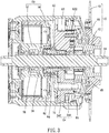
FIG. 3 is a longitudinal cross-sectional view of the preferred embodiment of the present invention; -
FIG. 4 is a transverse cross-sectional view of the preferred embodiment of the present invention, showing the relationship between a rotor of a motor and a ratchet; -
FIG. 5 is another transverse cross-sectional view of the preferred embodiment of the present invention, showing an idle planetary carrier; and -
FIG. 6 is similar toFIG. 5 but shows the planetary carrier rotating. - Referring to
FIGs. 1 ,2 , in a preferred embodiment of the present invention, a centrally-positionedpower output mechanism 10 is for use with a power-assisted bicycle and comprises ahousing 20, acrankshaft 30, alarge sprocket 40, amotor 50, and atransmission unit 60. - The
housing 20 has acasing 22 and anend cover 24 fixed to one end of thecasing 22. - The
crankshaft 30 is inserted through thehousing 20. The two ends of thecrankshaft 30 protrude out of thehousing 20 and both are connected with acrank 32 respectively. - Referring to
FIG. 2 andFIG. 3 , thelarge sprocket 40 has a transmission bushing 42, asprocket holder 44 fixed to the transmission bushing 42, and asprocket body 46 fixed to thesprocket holder 44. One end of thetransmission bushing 42 extends into thehousing 20 and is connected to thecrankshaft 30 by means of aratchet 48, such that thelarge sprocket 40 is driven by thecrankshaft 30 to undergo unidirectional rotation. - The
motor 50 is disposed inside thehousing 20 and has astator 52 and arotor 54. Therotor 54 is sleeved onto thecrankshaft 30, and twoball bearings 56 are disposed between therotor 54 and thecrankshaft 30, thereby facilitating engagement and positioning of therotor 54 and thecrankshaft 30. When supplied with electric current, thestator 52 drives therotor 54 to rotate relative to thestator 52 and thecrankshaft 30. - Referring to
FIG. 2 through FIG. 4 , thetransmission unit 60 has aring gear 61, asun gear 62, aplanetary carrier 63, and threeplanetary gears 64. The outer circumferential surface of thering gear 61 is fixed to the inner wall surface of thecasing 22 of thehousing 20. Thesun gear 62 is coaxially sleeved onto thecrankshaft 30 and has ahelical gear 70 and aratchet 80. Theratchet 80 has anexternal ratchet body 82, aninternal ratchet body 84, and threeratchet teeth 86. Theexternal ratchet body 82 and therotor 54 of themotor 50 are coupled together by two opposing coupling keys 88 (or at least a coupling key 88 can do the same function) Theinternal ratchet body 84 is integrally coaxially connected to one end of thehelical gear 70. Theratchet teeth 86 are disposed between theexternal ratchet body 82 and theinternal ratchet body 84. Theplanetary carrier 63 is rotatably sleeved onto thecrankshaft 30 and connected to the transmission bushing 42 of thelarge sprocket 40 by means of a plurality ofbolts 632, such that theplanetary carrier 63 synchronously drives the rotation of thelarge sprocket 40 by means of the transmission bushing 42. A ball bearing 65 is disposed between theplanetary carrier 63 and theinternal ratchet body 84 to facilitate the engagement and positioning of theplanetary carrier 63 and the internal ratchet 84.Each of theplanetary gears 64, theplanetary carrier 63, and the transmission bushing 42 of thelarge sprocket 40 are connected by a planetary gear shaft 66.Each of theplanetary gears 64 has ahelical tooth portion 642 and aplanetary tooth portion 644. Thehelical tooth portion 642 is engaged with thehelical gear 70 of thesun gear 62. Theplanetary tooth portion 644 is coaxially connected to a lateral side of thehelical tooth portion 642 and is engaged with thering gear 61, as shown inFIG. 5 . - The structure of the centrally-positioned
power output mechanism 10 of the present invention is described above. The operation, assembly process, and features of the centrally-positionedpower output mechanism 10 of the present invention is described below. - As soon as a bicyclist starts cycling, the
crankshaft 30 gets driven by twocranks 32 and starts to rotate. During the rotation process of thecrankshaft 30, theratchet 48 drives the transmission bushing 42 of thelarge sprocket 40 to undergo unidirectional rotation and thereby drives thelarge sprocket 40 to effectuate power output. - To generate an auxiliary driving force, electric power is supplied to the
stator 52 of themotor 50 to drive therotor 54 to rotate. During the rotation process of therotor 54, theexternal ratchet body 82 of theratchet 80 of thesun gear 62 is driven to rotate first. Theexternal ratchet body 82 drives theinternal ratchet body 84 to rotate by means of theratchet teeth 86. Then, theinternal ratchet body 84 drives thehelical gear 70 to rotate, such that thesun gear 62 is driven by therotor 54 of themotor 50 to rotate. The rotation of thesun gear 62 drives theplanetary gears 64 to rotate, as thehelical gear 70 is engaged with thehelical tooth portions 642 of theplanetary gears 64; meanwhile, with thering gear 61 being stationary, each of theplanetary gears 64 revolves along the circumference of thering gear 61 and drive theplanetary carrier 63 to rotate, as shown inFIG. 5 andFIG. 6 . Hence, theplanetary carrier 63 drives thetransmission bushing 42 of thelarge sprocket 40 to rotate and thereby drives thelarge sprocket 40 to effectuate generation of the auxiliary driving force. - In conclusion, the centrally-positioned
power output mechanism 10 of the present invention is characterized in that: thesun gear 62 enables theratchet 80 and thehelical gear 70 to be coupled together by coaxial connection and thus not only surpasses its conventional counterparts in compactness but also keeps the respective features of theratchet 80 and thehelical gear 70, such as smooth operation, low noise, high output torque, and elimination of gaps, to thereby effectively solve the problems of the operational noise and vibration caused by a processing error. Furthermore, the centrally-positionedpower output mechanism 10 of the present invention is characterized by theball bearing 65 disposed between thesun gear 62 and theplanetary carrier 63 to facilitate engagement therebetween and thus enhance durability and stability of the structure in its entirety. - Constituent elements of the present invention are disclosed above by a preferred embodiment. However, persons skilled in the art should understand that the preferred embodiment is illustrative of the present invention only, but should not be interpreted as restrictive of the scope of the present invention.
Claims (7)
- A centrally-positioned power output mechanism (10) for a power-assisted bicycle, comprising:a housing (20);a crankshaft (30) rotatably inserted through the housing (20);a large sprocket (40) connected to an end of the crankshaft (30) and having a transmission bushing (42) extending into the housing (20);a motor (50) disposed inside the housing (20), sleeved onto the crankshaft (30), and having a rotor (52) rotatable relative to the crankshaft (30); anda transmission unit (60) having a ring gear (61);wherein the transmission unit (60) further has a sun gear (62), a planetary carrier (63), and at least two planetary gears (64), the sun gear (62) being coaxially sleeved onto the crankshaft (30) and the centrally-positioned power output mechanism is characterized in that the ring gear (61) is fixed to the housing (20) and disposed therein, and having a helical gear (70) and a ratchet (80), the ratchet (80) being fixed to the rotor (54) of the motor (50) and coaxially connected to the helical gear (70), the planetary carrier (63) being rotatably sleeved onto the crankshaft (30) and connected to the transmission bushing (42) of the large sprocket (40), the planetary gears (64) each being rotatably disposed at the planetary carrier (63) and having a helical tooth portion (642) and a planetary tooth portion (644), the helical tooth portion (642) being engaged with the helical gear (70) of the sun gear (62), and the planetary tooth portion (644) being coaxially connected to a lateral side of the helical tooth portion (642) and being engaged with the ring gear.
- The centrally-positioned power output mechanism (10) of claim 1, wherein the ratchet (80) of the sun gear (62) has an external ratchet body (82), an internal ratchet body (84), and a plurality of ratchet teeth (86), the external ratchet body (82) is fixed to the rotor (54) of the motor (50), the internal ratchet body (84) is integrally coaxially connected to the helical gear (70), and each of the ratchet teeth (86) is disposed between the external ratchet body (82) and the internal ratchet body (84).
- The centrally-positioned power output mechanism (10) of claim 2, wherein the external ratchet body (82) of the ratchet (80) and the rotor (54) of the motor (50) is coupled together by at least a coupling key (88).
- The centrally-positioned power output mechanism (10) of claim 2 or 3, wherein a ball bearing (65) is disposed between the internal ratchet body (84) of the ratchet (80) and the planetary carrier (63).
- The centrally-positioned power output mechanism (10) of claim 4, wherein at least a ball bearing is disposed between the crankshaft (30) and the rotor (54) of the motor (50).
- The centrally-positioned power output mechanism (10) of claim 5, wherein a transmission bushing (42) of the large sprocket (40) is connected to the crankshaft (30) by a ratchet (48).
- The centrally-positioned power output mechanism (10) of claim 6, wherein the transmission bushing (42) of the large sprocket (40), the planetary carrier (63), and each of the planetary gears (64) are connected by a planetary gear shaft (66).
Applications Claiming Priority (1)
| Application Number | Priority Date | Filing Date | Title |
|---|---|---|---|
| TW101222985U TWM453636U (en) | 2012-11-27 | 2012-11-27 | Intermediate power output mechanism for electric power-assisted bicycle |
Publications (2)
| Publication Number | Publication Date |
|---|---|
| EP2735501A1 EP2735501A1 (en) | 2014-05-28 |
| EP2735501B1 true EP2735501B1 (en) | 2018-06-27 |
Family
ID=49080028
Family Applications (1)
| Application Number | Title | Priority Date | Filing Date |
|---|---|---|---|
| EP13194566.9A Active EP2735501B1 (en) | 2012-11-27 | 2013-11-27 | Centrally-positioned power output mechanism of power-assisted bicycle |
Country Status (2)
| Country | Link |
|---|---|
| EP (1) | EP2735501B1 (en) |
| TW (1) | TWM453636U (en) |
Cited By (1)
| Publication number | Priority date | Publication date | Assignee | Title |
|---|---|---|---|---|
| US11787551B1 (en) | 2022-10-06 | 2023-10-17 | Archer Aviation, Inc. | Vertical takeoff and landing aircraft electric engine configuration |
Families Citing this family (6)
| Publication number | Priority date | Publication date | Assignee | Title |
|---|---|---|---|---|
| EP3165438B1 (en) * | 2014-07-01 | 2021-06-09 | Panasonic Intellectual Property Management Co., Ltd. | Electric assist bicycle |
| BE1022240B1 (en) | 2014-09-02 | 2016-03-04 | E2 Drives Sa | POWER UNIT FOR A PEDAL VEHICLE |
| JP2016182851A (en) * | 2015-03-25 | 2016-10-20 | 株式会社シマノ | Drive unit for bicycle |
| JP6515019B2 (en) * | 2015-11-30 | 2019-05-15 | 株式会社シマノ | Bicycle drive unit |
| CN113460212B (en) * | 2021-06-10 | 2022-12-16 | 浙江夏厦精密制造股份有限公司 | Driving part of electric power-assisted bicycle |
| CN113715952A (en) * | 2021-08-23 | 2021-11-30 | 爱克玛电驱动系统(苏州)有限公司 | Resultant force output middle shaft motor of electric bicycle |
Citations (2)
| Publication number | Priority date | Publication date | Assignee | Title |
|---|---|---|---|---|
| US20020014366A1 (en) * | 1999-01-20 | 2002-02-07 | Turner James R. | Electric bicycle and methods |
| EP2298636A1 (en) * | 2009-09-18 | 2011-03-23 | Schaeffler Technologies AG & Co. KG | Gear assembly for a bicycle with an auxiliary drive |
Family Cites Families (5)
| Publication number | Priority date | Publication date | Assignee | Title |
|---|---|---|---|---|
| JPH09169290A (en) * | 1995-10-20 | 1997-06-30 | Mitsubishi Heavy Ind Ltd | Bicycle with auxiliary driving device and motor direct-coupled planetary roller speed reducing device |
| JPH10305794A (en) * | 1997-05-07 | 1998-11-17 | Sumitomo Heavy Ind Ltd | Motor-assisted bicycle |
| JP3974386B2 (en) | 2001-11-19 | 2007-09-12 | ヤマハモーターエレクトロニクス株式会社 | Reduction gear mechanism for electric drive |
| DE102010051727A1 (en) * | 2010-11-19 | 2012-05-24 | Pinion Gmbh | drive unit |
| CN102514679B (en) * | 2011-12-29 | 2014-01-01 | 太仓市悦博电动科技有限公司 | Motor drive system in coil sensing torque sensor |
-
2012
- 2012-11-27 TW TW101222985U patent/TWM453636U/en not_active IP Right Cessation
-
2013
- 2013-11-27 EP EP13194566.9A patent/EP2735501B1/en active Active
Patent Citations (2)
| Publication number | Priority date | Publication date | Assignee | Title |
|---|---|---|---|---|
| US20020014366A1 (en) * | 1999-01-20 | 2002-02-07 | Turner James R. | Electric bicycle and methods |
| EP2298636A1 (en) * | 2009-09-18 | 2011-03-23 | Schaeffler Technologies AG & Co. KG | Gear assembly for a bicycle with an auxiliary drive |
Cited By (4)
| Publication number | Priority date | Publication date | Assignee | Title |
|---|---|---|---|---|
| US11787551B1 (en) | 2022-10-06 | 2023-10-17 | Archer Aviation, Inc. | Vertical takeoff and landing aircraft electric engine configuration |
| US11820523B1 (en) | 2022-10-06 | 2023-11-21 | Archer Aviation, Inc. | Systems and methods for, and components of, gearboxes for eVTOL aircraft |
| US11912424B1 (en) | 2022-10-06 | 2024-02-27 | Archer Aviation Inc. | Systems and methods for improved gearboxes for eVTOL aircraft |
| US11958621B1 (en) | 2022-10-06 | 2024-04-16 | Archer Aviation, Inc. | Systems and methods for, and components of, gearboxes for eVTOL aircraft |
Also Published As
| Publication number | Publication date |
|---|---|
| EP2735501A1 (en) | 2014-05-28 |
| TWM453636U (en) | 2013-05-21 |
Similar Documents
| Publication | Publication Date | Title |
|---|---|---|
| EP2735501B1 (en) | Centrally-positioned power output mechanism of power-assisted bicycle | |
| US8590655B2 (en) | Pedal driven apparatus having a motor | |
| RU2705508C1 (en) | System with motor-reducer for two-wheel or three-wheeled vehicles installed coaxially with vehicle carriage, and vehicle with such system | |
| US8652000B2 (en) | Clutch type driving mechanism for hybrid powered vehicle | |
| US6974399B2 (en) | Hub motor mechanism | |
| US20130162112A1 (en) | Motor-Gear Unit | |
| CN101764463B (en) | Center shaft type electromobile motor | |
| EP2724926A1 (en) | Central axle power output mechanism | |
| US10150534B2 (en) | Motorized gear reducer | |
| CN111927935A (en) | Harmonic drive system and electric bicycle | |
| EP2900547B1 (en) | A pedal driven apparatus having a motor | |
| CN110949597A (en) | Middle-mounted driving device and bicycle with same | |
| CN218489845U (en) | Bicycle, electric middle drive unit and gear box thereof | |
| CN203064151U (en) | Middle-arranged power output mechanism of electric power bicycle | |
| CN212401474U (en) | Mid-motor and electric power-assisted bicycle | |
| CN106864659B (en) | Multifunctional power-assisted speed reducer | |
| CN113993776B (en) | Electric gear motor assembly for a bicycle | |
| CN111846102A (en) | Mid-motor and electric power-assisted bicycle | |
| TWI813246B (en) | Power module of electric assisted bicycle | |
| WO2023236046A1 (en) | Power-assisted drive assembly | |
| CN211958981U (en) | Middle-mounted generator set for scooter | |
| JP3246169U (en) | Electrically assisted bicycle mid motor | |
| CN212401475U (en) | Mid-motor and electric power-assisted bicycle | |
| CN202609020U (en) | Centrally-mounted power output mechanism of electricity-aided bicycle | |
| CN211958974U (en) | Outer rotor type middle-placed motor for electric power-assisted vehicle |
Legal Events
| Date | Code | Title | Description |
|---|---|---|---|
| PUAI | Public reference made under article 153(3) epc to a published international application that has entered the european phase |
Free format text: ORIGINAL CODE: 0009012 |
|
| 17P | Request for examination filed |
Effective date: 20131127 |
|
| AK | Designated contracting states |
Kind code of ref document: A1 Designated state(s): AL AT BE BG CH CY CZ DE DK EE ES FI FR GB GR HR HU IE IS IT LI LT LU LV MC MK MT NL NO PL PT RO RS SE SI SK SM TR |
|
| AX | Request for extension of the european patent |
Extension state: BA ME |
|
| 17Q | First examination report despatched |
Effective date: 20160926 |
|
| STAA | Information on the status of an ep patent application or granted ep patent |
Free format text: STATUS: EXAMINATION IS IN PROGRESS |
|
| GRAP | Despatch of communication of intention to grant a patent |
Free format text: ORIGINAL CODE: EPIDOSNIGR1 |
|
| STAA | Information on the status of an ep patent application or granted ep patent |
Free format text: STATUS: GRANT OF PATENT IS INTENDED |
|
| INTG | Intention to grant announced |
Effective date: 20180117 |
|
| GRAS | Grant fee paid |
Free format text: ORIGINAL CODE: EPIDOSNIGR3 |
|
| GRAA | (expected) grant |
Free format text: ORIGINAL CODE: 0009210 |
|
| STAA | Information on the status of an ep patent application or granted ep patent |
Free format text: STATUS: THE PATENT HAS BEEN GRANTED |
|
| AK | Designated contracting states |
Kind code of ref document: B1 Designated state(s): AL AT BE BG CH CY CZ DE DK EE ES FI FR GB GR HR HU IE IS IT LI LT LU LV MC MK MT NL NO PL PT RO RS SE SI SK SM TR |
|
| REG | Reference to a national code |
Ref country code: GB Ref legal event code: FG4D |
|
| REG | Reference to a national code |
Ref country code: AT Ref legal event code: REF Ref document number: 1012056 Country of ref document: AT Kind code of ref document: T Effective date: 20180715 |
|
| REG | Reference to a national code |
Ref country code: IE Ref legal event code: FG4D |
|
| REG | Reference to a national code |
Ref country code: DE Ref legal event code: R096 Ref document number: 602013039359 Country of ref document: DE |
|
| PG25 | Lapsed in a contracting state [announced via postgrant information from national office to epo] |
Ref country code: FI Free format text: LAPSE BECAUSE OF FAILURE TO SUBMIT A TRANSLATION OF THE DESCRIPTION OR TO PAY THE FEE WITHIN THE PRESCRIBED TIME-LIMIT Effective date: 20180627 Ref country code: BG Free format text: LAPSE BECAUSE OF FAILURE TO SUBMIT A TRANSLATION OF THE DESCRIPTION OR TO PAY THE FEE WITHIN THE PRESCRIBED TIME-LIMIT Effective date: 20180927 Ref country code: LT Free format text: LAPSE BECAUSE OF FAILURE TO SUBMIT A TRANSLATION OF THE DESCRIPTION OR TO PAY THE FEE WITHIN THE PRESCRIBED TIME-LIMIT Effective date: 20180627 Ref country code: SE Free format text: LAPSE BECAUSE OF FAILURE TO SUBMIT A TRANSLATION OF THE DESCRIPTION OR TO PAY THE FEE WITHIN THE PRESCRIBED TIME-LIMIT Effective date: 20180627 Ref country code: NO Free format text: LAPSE BECAUSE OF FAILURE TO SUBMIT A TRANSLATION OF THE DESCRIPTION OR TO PAY THE FEE WITHIN THE PRESCRIBED TIME-LIMIT Effective date: 20180927 |
|
| REG | Reference to a national code |
Ref country code: NL Ref legal event code: MP Effective date: 20180627 |
|
| REG | Reference to a national code |
Ref country code: LT Ref legal event code: MG4D |
|
| PG25 | Lapsed in a contracting state [announced via postgrant information from national office to epo] |
Ref country code: GR Free format text: LAPSE BECAUSE OF FAILURE TO SUBMIT A TRANSLATION OF THE DESCRIPTION OR TO PAY THE FEE WITHIN THE PRESCRIBED TIME-LIMIT Effective date: 20180928 Ref country code: RS Free format text: LAPSE BECAUSE OF FAILURE TO SUBMIT A TRANSLATION OF THE DESCRIPTION OR TO PAY THE FEE WITHIN THE PRESCRIBED TIME-LIMIT Effective date: 20180627 Ref country code: HR Free format text: LAPSE BECAUSE OF FAILURE TO SUBMIT A TRANSLATION OF THE DESCRIPTION OR TO PAY THE FEE WITHIN THE PRESCRIBED TIME-LIMIT Effective date: 20180627 Ref country code: LV Free format text: LAPSE BECAUSE OF FAILURE TO SUBMIT A TRANSLATION OF THE DESCRIPTION OR TO PAY THE FEE WITHIN THE PRESCRIBED TIME-LIMIT Effective date: 20180627 |
|
| REG | Reference to a national code |
Ref country code: AT Ref legal event code: MK05 Ref document number: 1012056 Country of ref document: AT Kind code of ref document: T Effective date: 20180627 |
|
| PG25 | Lapsed in a contracting state [announced via postgrant information from national office to epo] |
Ref country code: NL Free format text: LAPSE BECAUSE OF FAILURE TO SUBMIT A TRANSLATION OF THE DESCRIPTION OR TO PAY THE FEE WITHIN THE PRESCRIBED TIME-LIMIT Effective date: 20180627 |
|
| PG25 | Lapsed in a contracting state [announced via postgrant information from national office to epo] |
Ref country code: AT Free format text: LAPSE BECAUSE OF FAILURE TO SUBMIT A TRANSLATION OF THE DESCRIPTION OR TO PAY THE FEE WITHIN THE PRESCRIBED TIME-LIMIT Effective date: 20180627 Ref country code: EE Free format text: LAPSE BECAUSE OF FAILURE TO SUBMIT A TRANSLATION OF THE DESCRIPTION OR TO PAY THE FEE WITHIN THE PRESCRIBED TIME-LIMIT Effective date: 20180627 Ref country code: IS Free format text: LAPSE BECAUSE OF FAILURE TO SUBMIT A TRANSLATION OF THE DESCRIPTION OR TO PAY THE FEE WITHIN THE PRESCRIBED TIME-LIMIT Effective date: 20181027 Ref country code: CZ Free format text: LAPSE BECAUSE OF FAILURE TO SUBMIT A TRANSLATION OF THE DESCRIPTION OR TO PAY THE FEE WITHIN THE PRESCRIBED TIME-LIMIT Effective date: 20180627 Ref country code: RO Free format text: LAPSE BECAUSE OF FAILURE TO SUBMIT A TRANSLATION OF THE DESCRIPTION OR TO PAY THE FEE WITHIN THE PRESCRIBED TIME-LIMIT Effective date: 20180627 Ref country code: SK Free format text: LAPSE BECAUSE OF FAILURE TO SUBMIT A TRANSLATION OF THE DESCRIPTION OR TO PAY THE FEE WITHIN THE PRESCRIBED TIME-LIMIT Effective date: 20180627 Ref country code: PL Free format text: LAPSE BECAUSE OF FAILURE TO SUBMIT A TRANSLATION OF THE DESCRIPTION OR TO PAY THE FEE WITHIN THE PRESCRIBED TIME-LIMIT Effective date: 20180627 |
|
| PG25 | Lapsed in a contracting state [announced via postgrant information from national office to epo] |
Ref country code: SM Free format text: LAPSE BECAUSE OF FAILURE TO SUBMIT A TRANSLATION OF THE DESCRIPTION OR TO PAY THE FEE WITHIN THE PRESCRIBED TIME-LIMIT Effective date: 20180627 Ref country code: IT Free format text: LAPSE BECAUSE OF FAILURE TO SUBMIT A TRANSLATION OF THE DESCRIPTION OR TO PAY THE FEE WITHIN THE PRESCRIBED TIME-LIMIT Effective date: 20180627 Ref country code: ES Free format text: LAPSE BECAUSE OF FAILURE TO SUBMIT A TRANSLATION OF THE DESCRIPTION OR TO PAY THE FEE WITHIN THE PRESCRIBED TIME-LIMIT Effective date: 20180627 |
|
| REG | Reference to a national code |
Ref country code: DE Ref legal event code: R097 Ref document number: 602013039359 Country of ref document: DE |
|
| PLBE | No opposition filed within time limit |
Free format text: ORIGINAL CODE: 0009261 |
|
| STAA | Information on the status of an ep patent application or granted ep patent |
Free format text: STATUS: NO OPPOSITION FILED WITHIN TIME LIMIT |
|
| PG25 | Lapsed in a contracting state [announced via postgrant information from national office to epo] |
Ref country code: DK Free format text: LAPSE BECAUSE OF FAILURE TO SUBMIT A TRANSLATION OF THE DESCRIPTION OR TO PAY THE FEE WITHIN THE PRESCRIBED TIME-LIMIT Effective date: 20180627 |
|
| 26N | No opposition filed |
Effective date: 20190328 |
|
| REG | Reference to a national code |
Ref country code: CH Ref legal event code: PL |
|
| GBPC | Gb: european patent ceased through non-payment of renewal fee |
Effective date: 20181127 |
|
| PG25 | Lapsed in a contracting state [announced via postgrant information from national office to epo] |
Ref country code: LU Free format text: LAPSE BECAUSE OF NON-PAYMENT OF DUE FEES Effective date: 20181127 Ref country code: MC Free format text: LAPSE BECAUSE OF FAILURE TO SUBMIT A TRANSLATION OF THE DESCRIPTION OR TO PAY THE FEE WITHIN THE PRESCRIBED TIME-LIMIT Effective date: 20180627 |
|
| REG | Reference to a national code |
Ref country code: IE Ref legal event code: MM4A |
|
| PG25 | Lapsed in a contracting state [announced via postgrant information from national office to epo] |
Ref country code: CH Free format text: LAPSE BECAUSE OF NON-PAYMENT OF DUE FEES Effective date: 20181130 Ref country code: SI Free format text: LAPSE BECAUSE OF FAILURE TO SUBMIT A TRANSLATION OF THE DESCRIPTION OR TO PAY THE FEE WITHIN THE PRESCRIBED TIME-LIMIT Effective date: 20180627 Ref country code: LI Free format text: LAPSE BECAUSE OF NON-PAYMENT OF DUE FEES Effective date: 20181130 |
|
| PG25 | Lapsed in a contracting state [announced via postgrant information from national office to epo] |
Ref country code: IE Free format text: LAPSE BECAUSE OF NON-PAYMENT OF DUE FEES Effective date: 20181127 |
|
| PG25 | Lapsed in a contracting state [announced via postgrant information from national office to epo] |
Ref country code: AL Free format text: LAPSE BECAUSE OF FAILURE TO SUBMIT A TRANSLATION OF THE DESCRIPTION OR TO PAY THE FEE WITHIN THE PRESCRIBED TIME-LIMIT Effective date: 20180627 |
|
| PG25 | Lapsed in a contracting state [announced via postgrant information from national office to epo] |
Ref country code: GB Free format text: LAPSE BECAUSE OF NON-PAYMENT OF DUE FEES Effective date: 20181127 |
|
| REG | Reference to a national code |
Ref country code: DE Ref legal event code: R082 Ref document number: 602013039359 Country of ref document: DE Representative=s name: 2K PATENT- UND RECHTSANWAELTE PARTNERSCHAFT MB, DE |
|
| PG25 | Lapsed in a contracting state [announced via postgrant information from national office to epo] |
Ref country code: MT Free format text: LAPSE BECAUSE OF NON-PAYMENT OF DUE FEES Effective date: 20181127 |
|
| PGFP | Annual fee paid to national office [announced via postgrant information from national office to epo] |
Ref country code: FR Payment date: 20191121 Year of fee payment: 7 |
|
| PG25 | Lapsed in a contracting state [announced via postgrant information from national office to epo] |
Ref country code: TR Free format text: LAPSE BECAUSE OF FAILURE TO SUBMIT A TRANSLATION OF THE DESCRIPTION OR TO PAY THE FEE WITHIN THE PRESCRIBED TIME-LIMIT Effective date: 20180627 |
|
| PG25 | Lapsed in a contracting state [announced via postgrant information from national office to epo] |
Ref country code: PT Free format text: LAPSE BECAUSE OF FAILURE TO SUBMIT A TRANSLATION OF THE DESCRIPTION OR TO PAY THE FEE WITHIN THE PRESCRIBED TIME-LIMIT Effective date: 20180627 |
|
| PG25 | Lapsed in a contracting state [announced via postgrant information from national office to epo] |
Ref country code: CY Free format text: LAPSE BECAUSE OF FAILURE TO SUBMIT A TRANSLATION OF THE DESCRIPTION OR TO PAY THE FEE WITHIN THE PRESCRIBED TIME-LIMIT Effective date: 20180627 Ref country code: MK Free format text: LAPSE BECAUSE OF NON-PAYMENT OF DUE FEES Effective date: 20180627 Ref country code: HU Free format text: LAPSE BECAUSE OF FAILURE TO SUBMIT A TRANSLATION OF THE DESCRIPTION OR TO PAY THE FEE WITHIN THE PRESCRIBED TIME-LIMIT; INVALID AB INITIO Effective date: 20131127 |
|
| PG25 | Lapsed in a contracting state [announced via postgrant information from national office to epo] |
Ref country code: FR Free format text: LAPSE BECAUSE OF NON-PAYMENT OF DUE FEES Effective date: 20201130 |
|
| PGFP | Annual fee paid to national office [announced via postgrant information from national office to epo] |
Ref country code: BE Payment date: 20221118 Year of fee payment: 10 |
|
| PGFP | Annual fee paid to national office [announced via postgrant information from national office to epo] |
Ref country code: DE Payment date: 20231129 Year of fee payment: 11 |
|
| PGFP | Annual fee paid to national office [announced via postgrant information from national office to epo] |
Ref country code: BE Payment date: 20231121 Year of fee payment: 11 |