EP2735375B1 - Use of tubes for the dispensing of liquid starting materials for rigid isocyanate-based foam in the production of composite elements based on isocyanate-based foams - Google Patents
Use of tubes for the dispensing of liquid starting materials for rigid isocyanate-based foam in the production of composite elements based on isocyanate-based foams Download PDFInfo
- Publication number
- EP2735375B1 EP2735375B1 EP14152154.2A EP14152154A EP2735375B1 EP 2735375 B1 EP2735375 B1 EP 2735375B1 EP 14152154 A EP14152154 A EP 14152154A EP 2735375 B1 EP2735375 B1 EP 2735375B1
- Authority
- EP
- European Patent Office
- Prior art keywords
- isocyanate
- tubes
- use according
- tube
- apertures
- Prior art date
- Legal status (The legal status is an assumption and is not a legal conclusion. Google has not performed a legal analysis and makes no representation as to the accuracy of the status listed.)
- Revoked
Links
- 239000006260 foam Substances 0.000 title claims description 70
- 239000012948 isocyanate Substances 0.000 title claims description 43
- 150000002513 isocyanates Chemical class 0.000 title claims description 43
- 239000007858 starting material Substances 0.000 title claims description 26
- 238000004519 manufacturing process Methods 0.000 title claims description 16
- 239000007788 liquid Substances 0.000 title claims description 15
- 239000002131 composite material Substances 0.000 title claims description 13
- 238000000034 method Methods 0.000 claims description 28
- 230000007423 decrease Effects 0.000 claims description 6
- 238000013461 design Methods 0.000 claims description 2
- 239000003054 catalyst Substances 0.000 description 23
- 239000000203 mixture Substances 0.000 description 22
- 239000004604 Blowing Agent Substances 0.000 description 20
- 239000011541 reaction mixture Substances 0.000 description 18
- 239000002318 adhesion promoter Substances 0.000 description 17
- 239000005056 polyisocyanate Substances 0.000 description 15
- 229920001228 polyisocyanate Polymers 0.000 description 15
- 239000004814 polyurethane Substances 0.000 description 15
- 239000011495 polyisocyanurate Substances 0.000 description 14
- 229920000582 polyisocyanurate Polymers 0.000 description 14
- 229920002635 polyurethane Polymers 0.000 description 14
- 150000001875 compounds Chemical class 0.000 description 11
- BDAGIHXWWSANSR-UHFFFAOYSA-N methanoic acid Natural products OC=O BDAGIHXWWSANSR-UHFFFAOYSA-N 0.000 description 10
- 229920005862 polyol Polymers 0.000 description 10
- 150000003077 polyols Chemical class 0.000 description 10
- UPMLOUAZCHDJJD-UHFFFAOYSA-N 4,4'-Diphenylmethane Diisocyanate Chemical compound C1=CC(N=C=O)=CC=C1CC1=CC=C(N=C=O)C=C1 UPMLOUAZCHDJJD-UHFFFAOYSA-N 0.000 description 8
- 238000005266 casting Methods 0.000 description 8
- OFBQJSOFQDEBGM-UHFFFAOYSA-N Pentane Chemical class CCCCC OFBQJSOFQDEBGM-UHFFFAOYSA-N 0.000 description 7
- 238000006243 chemical reaction Methods 0.000 description 7
- 239000003063 flame retardant Substances 0.000 description 7
- 125000002887 hydroxy group Chemical group [H]O* 0.000 description 7
- IQPQWNKOIGAROB-UHFFFAOYSA-N isocyanate group Chemical group [N-]=C=O IQPQWNKOIGAROB-UHFFFAOYSA-N 0.000 description 7
- CURLTUGMZLYLDI-UHFFFAOYSA-N Carbon dioxide Chemical compound O=C=O CURLTUGMZLYLDI-UHFFFAOYSA-N 0.000 description 6
- WSFSSNUMVMOOMR-UHFFFAOYSA-N Formaldehyde Chemical compound O=C WSFSSNUMVMOOMR-UHFFFAOYSA-N 0.000 description 6
- 229910000831 Steel Inorganic materials 0.000 description 6
- 239000000654 additive Substances 0.000 description 6
- 125000004432 carbon atom Chemical group C* 0.000 description 6
- 229910052751 metal Inorganic materials 0.000 description 6
- 239000002184 metal Substances 0.000 description 6
- 239000010959 steel Substances 0.000 description 6
- OSWFIVFLDKOXQC-UHFFFAOYSA-N 4-(3-methoxyphenyl)aniline Chemical compound COC1=CC=CC(C=2C=CC(N)=CC=2)=C1 OSWFIVFLDKOXQC-UHFFFAOYSA-N 0.000 description 5
- GOOHAUXETOMSMM-UHFFFAOYSA-N Propylene oxide Chemical compound CC1CO1 GOOHAUXETOMSMM-UHFFFAOYSA-N 0.000 description 5
- 229910052782 aluminium Inorganic materials 0.000 description 5
- XAGFODPZIPBFFR-UHFFFAOYSA-N aluminium Chemical compound [Al] XAGFODPZIPBFFR-UHFFFAOYSA-N 0.000 description 5
- 235000019253 formic acid Nutrition 0.000 description 5
- 125000004435 hydrogen atom Chemical group [H]* 0.000 description 5
- -1 polymethylene Polymers 0.000 description 5
- 239000003381 stabilizer Substances 0.000 description 5
- 239000000126 substance Substances 0.000 description 5
- XLYOFNOQVPJJNP-UHFFFAOYSA-N water Substances O XLYOFNOQVPJJNP-UHFFFAOYSA-N 0.000 description 5
- 239000004970 Chain extender Substances 0.000 description 4
- JOYRKODLDBILNP-UHFFFAOYSA-N Ethyl urethane Chemical compound CCOC(N)=O JOYRKODLDBILNP-UHFFFAOYSA-N 0.000 description 4
- 150000001298 alcohols Chemical class 0.000 description 4
- 239000003431 cross linking reagent Substances 0.000 description 4
- 230000007547 defect Effects 0.000 description 4
- ZFSLODLOARCGLH-UHFFFAOYSA-N isocyanuric acid Chemical group OC1=NC(O)=NC(O)=N1 ZFSLODLOARCGLH-UHFFFAOYSA-N 0.000 description 4
- 230000010355 oscillation Effects 0.000 description 4
- CSCPPACGZOOCGX-UHFFFAOYSA-N Acetone Chemical compound CC(C)=O CSCPPACGZOOCGX-UHFFFAOYSA-N 0.000 description 3
- PEDCQBHIVMGVHV-UHFFFAOYSA-N Glycerine Chemical compound OCC(O)CO PEDCQBHIVMGVHV-UHFFFAOYSA-N 0.000 description 3
- 229910019142 PO4 Inorganic materials 0.000 description 3
- 239000004721 Polyphenylene oxide Substances 0.000 description 3
- WYURNTSHIVDZCO-UHFFFAOYSA-N Tetrahydrofuran Chemical compound C1CCOC1 WYURNTSHIVDZCO-UHFFFAOYSA-N 0.000 description 3
- 125000002947 alkylene group Chemical group 0.000 description 3
- 239000001569 carbon dioxide Substances 0.000 description 3
- 229910002092 carbon dioxide Inorganic materials 0.000 description 3
- MTHSVFCYNBDYFN-UHFFFAOYSA-N diethylene glycol Chemical compound OCCOCCO MTHSVFCYNBDYFN-UHFFFAOYSA-N 0.000 description 3
- 239000011888 foil Substances 0.000 description 3
- 239000000463 material Substances 0.000 description 3
- NBIIXXVUZAFLBC-UHFFFAOYSA-K phosphate Chemical compound [O-]P([O-])([O-])=O NBIIXXVUZAFLBC-UHFFFAOYSA-K 0.000 description 3
- 239000010452 phosphate Substances 0.000 description 3
- 229920000570 polyether Polymers 0.000 description 3
- CXMXRPHRNRROMY-UHFFFAOYSA-N sebacic acid Chemical compound OC(=O)CCCCCCCCC(O)=O CXMXRPHRNRROMY-UHFFFAOYSA-N 0.000 description 3
- RUELTTOHQODFPA-UHFFFAOYSA-N toluene 2,6-diisocyanate Chemical compound CC1=C(N=C=O)C=CC=C1N=C=O RUELTTOHQODFPA-UHFFFAOYSA-N 0.000 description 3
- RNFJDJUURJAICM-UHFFFAOYSA-N 2,2,4,4,6,6-hexaphenoxy-1,3,5-triaza-2$l^{5},4$l^{5},6$l^{5}-triphosphacyclohexa-1,3,5-triene Chemical compound N=1P(OC=2C=CC=CC=2)(OC=2C=CC=CC=2)=NP(OC=2C=CC=CC=2)(OC=2C=CC=CC=2)=NP=1(OC=1C=CC=CC=1)OC1=CC=CC=C1 RNFJDJUURJAICM-UHFFFAOYSA-N 0.000 description 2
- HHDUMDVQUCBCEY-UHFFFAOYSA-N 4-[10,15,20-tris(4-carboxyphenyl)-21,23-dihydroporphyrin-5-yl]benzoic acid Chemical compound OC(=O)c1ccc(cc1)-c1c2ccc(n2)c(-c2ccc(cc2)C(O)=O)c2ccc([nH]2)c(-c2ccc(cc2)C(O)=O)c2ccc(n2)c(-c2ccc(cc2)C(O)=O)c2ccc1[nH]2 HHDUMDVQUCBCEY-UHFFFAOYSA-N 0.000 description 2
- CNPURSDMOWDNOQ-UHFFFAOYSA-N 4-methoxy-7h-pyrrolo[2,3-d]pyrimidin-2-amine Chemical compound COC1=NC(N)=NC2=C1C=CN2 CNPURSDMOWDNOQ-UHFFFAOYSA-N 0.000 description 2
- RYGMFSIKBFXOCR-UHFFFAOYSA-N Copper Chemical compound [Cu] RYGMFSIKBFXOCR-UHFFFAOYSA-N 0.000 description 2
- RGSFGYAAUTVSQA-UHFFFAOYSA-N Cyclopentane Chemical compound C1CCCC1 RGSFGYAAUTVSQA-UHFFFAOYSA-N 0.000 description 2
- LCGLNKUTAGEVQW-UHFFFAOYSA-N Dimethyl ether Chemical compound COC LCGLNKUTAGEVQW-UHFFFAOYSA-N 0.000 description 2
- XPDWGBQVDMORPB-UHFFFAOYSA-N Fluoroform Chemical compound FC(F)F XPDWGBQVDMORPB-UHFFFAOYSA-N 0.000 description 2
- VZCYOOQTPOCHFL-OWOJBTEDSA-N Fumaric acid Chemical compound OC(=O)\C=C\C(O)=O VZCYOOQTPOCHFL-OWOJBTEDSA-N 0.000 description 2
- ISWSIDIOOBJBQZ-UHFFFAOYSA-N Phenol Chemical compound OC1=CC=CC=C1 ISWSIDIOOBJBQZ-UHFFFAOYSA-N 0.000 description 2
- 229920005830 Polyurethane Foam Polymers 0.000 description 2
- ATUOYWHBWRKTHZ-UHFFFAOYSA-N Propane Chemical compound CCC ATUOYWHBWRKTHZ-UHFFFAOYSA-N 0.000 description 2
- XUIMIQQOPSSXEZ-UHFFFAOYSA-N Silicon Chemical compound [Si] XUIMIQQOPSSXEZ-UHFFFAOYSA-N 0.000 description 2
- CZMRCDWAGMRECN-UGDNZRGBSA-N Sucrose Chemical compound O[C@H]1[C@H](O)[C@@H](CO)O[C@@]1(CO)O[C@@H]1[C@H](O)[C@@H](O)[C@H](O)[C@@H](CO)O1 CZMRCDWAGMRECN-UGDNZRGBSA-N 0.000 description 2
- 229930006000 Sucrose Natural products 0.000 description 2
- KKEYFWRCBNTPAC-UHFFFAOYSA-N Terephthalic acid Chemical compound OC(=O)C1=CC=C(C(O)=O)C=C1 KKEYFWRCBNTPAC-UHFFFAOYSA-N 0.000 description 2
- ZJCCRDAZUWHFQH-UHFFFAOYSA-N Trimethylolpropane Chemical compound CCC(CO)(CO)CO ZJCCRDAZUWHFQH-UHFFFAOYSA-N 0.000 description 2
- WNLRTRBMVRJNCN-UHFFFAOYSA-N adipic acid Chemical compound OC(=O)CCCCC(O)=O WNLRTRBMVRJNCN-UHFFFAOYSA-N 0.000 description 2
- 150000001335 aliphatic alkanes Chemical class 0.000 description 2
- 150000001412 amines Chemical class 0.000 description 2
- 125000003118 aryl group Chemical group 0.000 description 2
- 230000015572 biosynthetic process Effects 0.000 description 2
- 238000009835 boiling Methods 0.000 description 2
- 239000007795 chemical reaction product Substances 0.000 description 2
- 239000003795 chemical substances by application Substances 0.000 description 2
- 229910052802 copper Inorganic materials 0.000 description 2
- 239000010949 copper Substances 0.000 description 2
- RWRIWBAIICGTTQ-UHFFFAOYSA-N difluoromethane Chemical compound FCF RWRIWBAIICGTTQ-UHFFFAOYSA-N 0.000 description 2
- 150000002009 diols Chemical class 0.000 description 2
- 230000009969 flowable effect Effects 0.000 description 2
- 239000004872 foam stabilizing agent Substances 0.000 description 2
- QWTDNUCVQCZILF-UHFFFAOYSA-N iso-pentane Natural products CCC(C)C QWTDNUCVQCZILF-UHFFFAOYSA-N 0.000 description 2
- QQVIHTHCMHWDBS-UHFFFAOYSA-N isophthalic acid Chemical compound OC(=O)C1=CC=CC(C(O)=O)=C1 QQVIHTHCMHWDBS-UHFFFAOYSA-N 0.000 description 2
- TZIHFWKZFHZASV-UHFFFAOYSA-N methyl formate Chemical compound COC=O TZIHFWKZFHZASV-UHFFFAOYSA-N 0.000 description 2
- BDJRBEYXGGNYIS-UHFFFAOYSA-N nonanedioic acid Chemical compound OC(=O)CCCCCCCC(O)=O BDJRBEYXGGNYIS-UHFFFAOYSA-N 0.000 description 2
- 150000002989 phenols Chemical class 0.000 description 2
- XNGIFLGASWRNHJ-UHFFFAOYSA-N phthalic acid Chemical compound OC(=O)C1=CC=CC=C1C(O)=O XNGIFLGASWRNHJ-UHFFFAOYSA-N 0.000 description 2
- 229920000768 polyamine Polymers 0.000 description 2
- 229920000728 polyester Polymers 0.000 description 2
- 229920006389 polyphenyl polymer Polymers 0.000 description 2
- 239000011496 polyurethane foam Substances 0.000 description 2
- SCVFZCLFOSHCOH-UHFFFAOYSA-M potassium acetate Chemical compound [K+].CC([O-])=O SCVFZCLFOSHCOH-UHFFFAOYSA-M 0.000 description 2
- 125000002924 primary amino group Chemical group [H]N([H])* 0.000 description 2
- 229910052710 silicon Inorganic materials 0.000 description 2
- 239000010703 silicon Substances 0.000 description 2
- TYFQFVWCELRYAO-UHFFFAOYSA-N suberic acid Chemical compound OC(=O)CCCCCCC(O)=O TYFQFVWCELRYAO-UHFFFAOYSA-N 0.000 description 2
- 239000005720 sucrose Substances 0.000 description 2
- 238000012360 testing method Methods 0.000 description 2
- VZCYOOQTPOCHFL-UHFFFAOYSA-N trans-butenedioic acid Natural products OC(=O)C=CC(O)=O VZCYOOQTPOCHFL-UHFFFAOYSA-N 0.000 description 2
- 230000007704 transition Effects 0.000 description 2
- XMNDMAQKWSQVOV-UHFFFAOYSA-N (2-methylphenyl) diphenyl phosphate Chemical compound CC1=CC=CC=C1OP(=O)(OC=1C=CC=CC=1)OC1=CC=CC=C1 XMNDMAQKWSQVOV-UHFFFAOYSA-N 0.000 description 1
- WRIDQFICGBMAFQ-UHFFFAOYSA-N (E)-8-Octadecenoic acid Natural products CCCCCCCCCC=CCCCCCCC(O)=O WRIDQFICGBMAFQ-UHFFFAOYSA-N 0.000 description 1
- LVGUZGTVOIAKKC-UHFFFAOYSA-N 1,1,1,2-tetrafluoroethane Chemical compound FCC(F)(F)F LVGUZGTVOIAKKC-UHFFFAOYSA-N 0.000 description 1
- WZLFPVPRZGTCKP-UHFFFAOYSA-N 1,1,1,3,3-pentafluorobutane Chemical compound CC(F)(F)CC(F)(F)F WZLFPVPRZGTCKP-UHFFFAOYSA-N 0.000 description 1
- NPNPZTNLOVBDOC-UHFFFAOYSA-N 1,1-difluoroethane Chemical compound CC(F)F NPNPZTNLOVBDOC-UHFFFAOYSA-N 0.000 description 1
- PCHXZXKMYCGVFA-UHFFFAOYSA-N 1,3-diazetidine-2,4-dione Chemical compound O=C1NC(=O)N1 PCHXZXKMYCGVFA-UHFFFAOYSA-N 0.000 description 1
- AATNZNJRDOVKDD-UHFFFAOYSA-N 1-[ethoxy(ethyl)phosphoryl]oxyethane Chemical compound CCOP(=O)(CC)OCC AATNZNJRDOVKDD-UHFFFAOYSA-N 0.000 description 1
- CXBDYQVECUFKRK-UHFFFAOYSA-N 1-methoxybutane Chemical compound CCCCOC CXBDYQVECUFKRK-UHFFFAOYSA-N 0.000 description 1
- RTBFRGCFXZNCOE-UHFFFAOYSA-N 1-methylsulfonylpiperidin-4-one Chemical compound CS(=O)(=O)N1CCC(=O)CC1 RTBFRGCFXZNCOE-UHFFFAOYSA-N 0.000 description 1
- RLYCRLGLCUXUPO-UHFFFAOYSA-N 2,6-diaminotoluene Chemical compound CC1=C(N)C=CC=C1N RLYCRLGLCUXUPO-UHFFFAOYSA-N 0.000 description 1
- OHKOAJUTRVTYSW-UHFFFAOYSA-N 2-[(2-aminophenyl)methyl]aniline Chemical compound NC1=CC=CC=C1CC1=CC=CC=C1N OHKOAJUTRVTYSW-UHFFFAOYSA-N 0.000 description 1
- FZZMTSNZRBFGGU-UHFFFAOYSA-N 2-chloro-7-fluoroquinazolin-4-amine Chemical compound FC1=CC=C2C(N)=NC(Cl)=NC2=C1 FZZMTSNZRBFGGU-UHFFFAOYSA-N 0.000 description 1
- LQJBNNIYVWPHFW-UHFFFAOYSA-N 20:1omega9c fatty acid Natural products CCCCCCCCCCC=CCCCCCCCC(O)=O LQJBNNIYVWPHFW-UHFFFAOYSA-N 0.000 description 1
- QSBYPNXLFMSGKH-UHFFFAOYSA-N 9-Heptadecensaeure Natural products CCCCCCCC=CCCCCCCCC(O)=O QSBYPNXLFMSGKH-UHFFFAOYSA-N 0.000 description 1
- KXDHJXZQYSOELW-UHFFFAOYSA-M Carbamate Chemical compound NC([O-])=O KXDHJXZQYSOELW-UHFFFAOYSA-M 0.000 description 1
- UGFAIRIUMAVXCW-UHFFFAOYSA-N Carbon monoxide Chemical compound [O+]#[C-] UGFAIRIUMAVXCW-UHFFFAOYSA-N 0.000 description 1
- XFXPMWWXUTWYJX-UHFFFAOYSA-N Cyanide Chemical compound N#[C-] XFXPMWWXUTWYJX-UHFFFAOYSA-N 0.000 description 1
- PMPVIKIVABFJJI-UHFFFAOYSA-N Cyclobutane Chemical compound C1CCC1 PMPVIKIVABFJJI-UHFFFAOYSA-N 0.000 description 1
- XDTMQSROBMDMFD-UHFFFAOYSA-N Cyclohexane Chemical compound C1CCCCC1 XDTMQSROBMDMFD-UHFFFAOYSA-N 0.000 description 1
- FBPFZTCFMRRESA-FSIIMWSLSA-N D-Glucitol Natural products OC[C@H](O)[C@H](O)[C@@H](O)[C@H](O)CO FBPFZTCFMRRESA-FSIIMWSLSA-N 0.000 description 1
- FBPFZTCFMRRESA-KVTDHHQDSA-N D-Mannitol Chemical compound OC[C@@H](O)[C@@H](O)[C@H](O)[C@H](O)CO FBPFZTCFMRRESA-KVTDHHQDSA-N 0.000 description 1
- FBPFZTCFMRRESA-JGWLITMVSA-N D-glucitol Chemical compound OC[C@H](O)[C@@H](O)[C@H](O)[C@H](O)CO FBPFZTCFMRRESA-JGWLITMVSA-N 0.000 description 1
- IAYPIBMASNFSPL-UHFFFAOYSA-N Ethylene oxide Chemical compound C1CO1 IAYPIBMASNFSPL-UHFFFAOYSA-N 0.000 description 1
- PIICEJLVQHRZGT-UHFFFAOYSA-N Ethylenediamine Chemical compound NCCN PIICEJLVQHRZGT-UHFFFAOYSA-N 0.000 description 1
- WQZGKKKJIJFFOK-GASJEMHNSA-N Glucose Natural products OC[C@H]1OC(O)[C@H](O)[C@@H](O)[C@@H]1O WQZGKKKJIJFFOK-GASJEMHNSA-N 0.000 description 1
- 239000002841 Lewis acid Substances 0.000 description 1
- 229930195725 Mannitol Natural products 0.000 description 1
- 229920000877 Melamine resin Polymers 0.000 description 1
- XOBKSJJDNFUZPF-UHFFFAOYSA-N Methoxyethane Chemical compound CCOC XOBKSJJDNFUZPF-UHFFFAOYSA-N 0.000 description 1
- 239000005642 Oleic acid Substances 0.000 description 1
- ZQPPMHVWECSIRJ-UHFFFAOYSA-N Oleic acid Natural products CCCCCCCCC=CCCCCCCCC(O)=O ZQPPMHVWECSIRJ-UHFFFAOYSA-N 0.000 description 1
- CBENFWSGALASAD-UHFFFAOYSA-N Ozone Chemical compound [O-][O+]=O CBENFWSGALASAD-UHFFFAOYSA-N 0.000 description 1
- LGRFSURHDFAFJT-UHFFFAOYSA-N Phthalic anhydride Natural products C1=CC=C2C(=O)OC(=O)C2=C1 LGRFSURHDFAFJT-UHFFFAOYSA-N 0.000 description 1
- OFOBLEOULBTSOW-UHFFFAOYSA-N Propanedioic acid Natural products OC(=O)CC(O)=O OFOBLEOULBTSOW-UHFFFAOYSA-N 0.000 description 1
- AWMVMTVKBNGEAK-UHFFFAOYSA-N Styrene oxide Chemical compound C1OC1C1=CC=CC=C1 AWMVMTVKBNGEAK-UHFFFAOYSA-N 0.000 description 1
- KDYFGRWQOYBRFD-UHFFFAOYSA-N Succinic acid Natural products OC(=O)CCC(O)=O KDYFGRWQOYBRFD-UHFFFAOYSA-N 0.000 description 1
- ATJFFYVFTNAWJD-UHFFFAOYSA-N Tin Chemical compound [Sn] ATJFFYVFTNAWJD-UHFFFAOYSA-N 0.000 description 1
- 238000009825 accumulation Methods 0.000 description 1
- 150000001241 acetals Chemical class 0.000 description 1
- 239000013543 active substance Substances 0.000 description 1
- 239000000853 adhesive Substances 0.000 description 1
- 239000001361 adipic acid Substances 0.000 description 1
- 235000011037 adipic acid Nutrition 0.000 description 1
- 230000002411 adverse Effects 0.000 description 1
- 125000001931 aliphatic group Chemical group 0.000 description 1
- 150000008044 alkali metal hydroxides Chemical class 0.000 description 1
- 125000000217 alkyl group Chemical group 0.000 description 1
- 150000001409 amidines Chemical class 0.000 description 1
- JFCQEDHGNNZCLN-UHFFFAOYSA-N anhydrous glutaric acid Natural products OC(=O)CCCC(O)=O JFCQEDHGNNZCLN-UHFFFAOYSA-N 0.000 description 1
- 238000010539 anionic addition polymerization reaction Methods 0.000 description 1
- 239000003429 antifungal agent Substances 0.000 description 1
- 239000003963 antioxidant agent Substances 0.000 description 1
- 239000002216 antistatic agent Substances 0.000 description 1
- 239000000022 bacteriostatic agent Substances 0.000 description 1
- 239000002585 base Substances 0.000 description 1
- WQZGKKKJIJFFOK-VFUOTHLCSA-N beta-D-glucose Chemical compound OC[C@H]1O[C@@H](O)[C@H](O)[C@@H](O)[C@@H]1O WQZGKKKJIJFFOK-VFUOTHLCSA-N 0.000 description 1
- 238000007664 blowing Methods 0.000 description 1
- KDYFGRWQOYBRFD-NUQCWPJISA-N butanedioic acid Chemical compound O[14C](=O)CC[14C](O)=O KDYFGRWQOYBRFD-NUQCWPJISA-N 0.000 description 1
- JHIWVOJDXOSYLW-UHFFFAOYSA-N butyl 2,2-difluorocyclopropane-1-carboxylate Chemical compound CCCCOC(=O)C1CC1(F)F JHIWVOJDXOSYLW-UHFFFAOYSA-N 0.000 description 1
- 150000001718 carbodiimides Chemical class 0.000 description 1
- 229910002091 carbon monoxide Inorganic materials 0.000 description 1
- 150000007942 carboxylates Chemical class 0.000 description 1
- 150000001732 carboxylic acid derivatives Chemical class 0.000 description 1
- 150000001735 carboxylic acids Chemical class 0.000 description 1
- 239000002666 chemical blowing agent Substances 0.000 description 1
- 230000000052 comparative effect Effects 0.000 description 1
- 238000009833 condensation Methods 0.000 description 1
- 230000005494 condensation Effects 0.000 description 1
- 239000007859 condensation product Substances 0.000 description 1
- 238000010276 construction Methods 0.000 description 1
- 238000007796 conventional method Methods 0.000 description 1
- 150000001924 cycloalkanes Chemical class 0.000 description 1
- 150000001983 dialkylethers Chemical class 0.000 description 1
- AFABGHUZZDYHJO-UHFFFAOYSA-N dimethyl butane Natural products CCCC(C)C AFABGHUZZDYHJO-UHFFFAOYSA-N 0.000 description 1
- 239000000975 dye Substances 0.000 description 1
- 230000000694 effects Effects 0.000 description 1
- 230000008030 elimination Effects 0.000 description 1
- 238000003379 elimination reaction Methods 0.000 description 1
- 238000005516 engineering process Methods 0.000 description 1
- 150000002148 esters Chemical class 0.000 description 1
- 239000000945 filler Substances 0.000 description 1
- 238000005187 foaming Methods 0.000 description 1
- 239000001530 fumaric acid Substances 0.000 description 1
- 230000001408 fungistatic effect Effects 0.000 description 1
- 239000011521 glass Substances 0.000 description 1
- 239000008103 glucose Substances 0.000 description 1
- UKACHOXRXFQJFN-UHFFFAOYSA-N heptafluoropropane Chemical compound FC(F)C(F)(F)C(F)(F)F UKACHOXRXFQJFN-UHFFFAOYSA-N 0.000 description 1
- DMEGYFMYUHOHGS-UHFFFAOYSA-N heptamethylene Natural products C1CCCCCC1 DMEGYFMYUHOHGS-UHFFFAOYSA-N 0.000 description 1
- 230000007062 hydrolysis Effects 0.000 description 1
- 238000006460 hydrolysis reaction Methods 0.000 description 1
- 150000002460 imidazoles Chemical class 0.000 description 1
- 238000009413 insulation Methods 0.000 description 1
- 230000001788 irregular Effects 0.000 description 1
- NNPPMTNAJDCUHE-UHFFFAOYSA-N isobutane Chemical compound CC(C)C NNPPMTNAJDCUHE-UHFFFAOYSA-N 0.000 description 1
- QXJSBBXBKPUZAA-UHFFFAOYSA-N isooleic acid Natural products CCCCCCCC=CCCCCCCCCC(O)=O QXJSBBXBKPUZAA-UHFFFAOYSA-N 0.000 description 1
- 150000002576 ketones Chemical class 0.000 description 1
- 150000007517 lewis acids Chemical class 0.000 description 1
- 238000012423 maintenance Methods 0.000 description 1
- VZCYOOQTPOCHFL-UPHRSURJSA-N maleic acid Chemical compound OC(=O)\C=C/C(O)=O VZCYOOQTPOCHFL-UPHRSURJSA-N 0.000 description 1
- 239000011976 maleic acid Substances 0.000 description 1
- 239000000594 mannitol Substances 0.000 description 1
- 235000010355 mannitol Nutrition 0.000 description 1
- JDSHMPZPIAZGSV-UHFFFAOYSA-N melamine Chemical compound NC1=NC(N)=NC(N)=N1 JDSHMPZPIAZGSV-UHFFFAOYSA-N 0.000 description 1
- SYSQUGFVNFXIIT-UHFFFAOYSA-N n-[4-(1,3-benzoxazol-2-yl)phenyl]-4-nitrobenzenesulfonamide Chemical class C1=CC([N+](=O)[O-])=CC=C1S(=O)(=O)NC1=CC=C(C=2OC3=CC=CC=C3N=2)C=C1 SYSQUGFVNFXIIT-UHFFFAOYSA-N 0.000 description 1
- IJDNQMDRQITEOD-UHFFFAOYSA-N n-butane Chemical compound CCCC IJDNQMDRQITEOD-UHFFFAOYSA-N 0.000 description 1
- KYTZHLUVELPASH-UHFFFAOYSA-N naphthalene-1,2-dicarboxylic acid Chemical class C1=CC=CC2=C(C(O)=O)C(C(=O)O)=CC=C21 KYTZHLUVELPASH-UHFFFAOYSA-N 0.000 description 1
- ZQPPMHVWECSIRJ-KTKRTIGZSA-N oleic acid Chemical compound CCCCCCCC\C=C/CCCCCCCC(O)=O ZQPPMHVWECSIRJ-KTKRTIGZSA-N 0.000 description 1
- 230000003287 optical effect Effects 0.000 description 1
- 150000002902 organometallic compounds Chemical class 0.000 description 1
- WXZMFSXDPGVJKK-UHFFFAOYSA-N pentaerythritol Chemical compound OCC(CO)(CO)CO WXZMFSXDPGVJKK-UHFFFAOYSA-N 0.000 description 1
- MSSNHSVIGIHOJA-UHFFFAOYSA-N pentafluoropropane Chemical compound FC(F)CC(F)(F)F MSSNHSVIGIHOJA-UHFFFAOYSA-N 0.000 description 1
- 150000004986 phenylenediamines Chemical class 0.000 description 1
- 125000004437 phosphorous atom Chemical group 0.000 description 1
- 239000000049 pigment Substances 0.000 description 1
- 238000009832 plasma treatment Methods 0.000 description 1
- 229920003023 plastic Polymers 0.000 description 1
- 239000004033 plastic Substances 0.000 description 1
- 235000011056 potassium acetate Nutrition 0.000 description 1
- 239000000047 product Substances 0.000 description 1
- 239000001294 propane Substances 0.000 description 1
- 230000000630 rising effect Effects 0.000 description 1
- 150000003839 salts Chemical class 0.000 description 1
- 150000005619 secondary aliphatic amines Chemical class 0.000 description 1
- 239000000600 sorbitol Substances 0.000 description 1
- 238000005507 spraying Methods 0.000 description 1
- 229910001220 stainless steel Inorganic materials 0.000 description 1
- 239000010935 stainless steel Substances 0.000 description 1
- 238000009864 tensile test Methods 0.000 description 1
- YLQBMQCUIZJEEH-UHFFFAOYSA-N tetrahydrofuran Natural products C=1C=COC=1 YLQBMQCUIZJEEH-UHFFFAOYSA-N 0.000 description 1
- CZDYPVPMEAXLPK-UHFFFAOYSA-N tetramethylsilane Chemical compound C[Si](C)(C)C CZDYPVPMEAXLPK-UHFFFAOYSA-N 0.000 description 1
- DQWPFSLDHJDLRL-UHFFFAOYSA-N triethyl phosphate Chemical compound CCOP(=O)(OCC)OCC DQWPFSLDHJDLRL-UHFFFAOYSA-N 0.000 description 1
- 150000004072 triols Chemical class 0.000 description 1
- 239000005436 troposphere Substances 0.000 description 1
- AVWRKZWQTYIKIY-UHFFFAOYSA-N urea-1-carboxylic acid Chemical compound NC(=O)NC(O)=O AVWRKZWQTYIKIY-UHFFFAOYSA-N 0.000 description 1
Images
Classifications
-
- B—PERFORMING OPERATIONS; TRANSPORTING
- B05—SPRAYING OR ATOMISING IN GENERAL; APPLYING FLUENT MATERIALS TO SURFACES, IN GENERAL
- B05C—APPARATUS FOR APPLYING FLUENT MATERIALS TO SURFACES, IN GENERAL
- B05C5/00—Apparatus in which liquid or other fluent material is projected, poured or allowed to flow on to the surface of the work
- B05C5/02—Apparatus in which liquid or other fluent material is projected, poured or allowed to flow on to the surface of the work the liquid or other fluent material being discharged through an outlet orifice by pressure, e.g. from an outlet device in contact or almost in contact, with the work
-
- C—CHEMISTRY; METALLURGY
- C09—DYES; PAINTS; POLISHES; NATURAL RESINS; ADHESIVES; COMPOSITIONS NOT OTHERWISE PROVIDED FOR; APPLICATIONS OF MATERIALS NOT OTHERWISE PROVIDED FOR
- C09D—COATING COMPOSITIONS, e.g. PAINTS, VARNISHES OR LACQUERS; FILLING PASTES; CHEMICAL PAINT OR INK REMOVERS; INKS; CORRECTING FLUIDS; WOODSTAINS; PASTES OR SOLIDS FOR COLOURING OR PRINTING; USE OF MATERIALS THEREFOR
- C09D175/00—Coating compositions based on polyureas or polyurethanes; Coating compositions based on derivatives of such polymers
- C09D175/04—Polyurethanes
- C09D175/08—Polyurethanes from polyethers
-
- B—PERFORMING OPERATIONS; TRANSPORTING
- B29—WORKING OF PLASTICS; WORKING OF SUBSTANCES IN A PLASTIC STATE IN GENERAL
- B29C—SHAPING OR JOINING OF PLASTICS; SHAPING OF MATERIAL IN A PLASTIC STATE, NOT OTHERWISE PROVIDED FOR; AFTER-TREATMENT OF THE SHAPED PRODUCTS, e.g. REPAIRING
- B29C31/00—Handling, e.g. feeding of the material to be shaped, storage of plastics material before moulding; Automation, i.e. automated handling lines in plastics processing plants, e.g. using manipulators or robots
- B29C31/04—Feeding of the material to be moulded, e.g. into a mould cavity
- B29C31/042—Feeding of the material to be moulded, e.g. into a mould cavity using dispensing heads, e.g. extruders, placed over or apart from the moulds
-
- B—PERFORMING OPERATIONS; TRANSPORTING
- B29—WORKING OF PLASTICS; WORKING OF SUBSTANCES IN A PLASTIC STATE IN GENERAL
- B29C—SHAPING OR JOINING OF PLASTICS; SHAPING OF MATERIAL IN A PLASTIC STATE, NOT OTHERWISE PROVIDED FOR; AFTER-TREATMENT OF THE SHAPED PRODUCTS, e.g. REPAIRING
- B29C31/00—Handling, e.g. feeding of the material to be shaped, storage of plastics material before moulding; Automation, i.e. automated handling lines in plastics processing plants, e.g. using manipulators or robots
- B29C31/04—Feeding of the material to be moulded, e.g. into a mould cavity
-
- B—PERFORMING OPERATIONS; TRANSPORTING
- B29—WORKING OF PLASTICS; WORKING OF SUBSTANCES IN A PLASTIC STATE IN GENERAL
- B29C—SHAPING OR JOINING OF PLASTICS; SHAPING OF MATERIAL IN A PLASTIC STATE, NOT OTHERWISE PROVIDED FOR; AFTER-TREATMENT OF THE SHAPED PRODUCTS, e.g. REPAIRING
- B29C44/00—Shaping by internal pressure generated in the material, e.g. swelling or foaming ; Producing porous or cellular expanded plastics articles
- B29C44/34—Auxiliary operations
- B29C44/36—Feeding the material to be shaped
- B29C44/46—Feeding the material to be shaped into an open space or onto moving surfaces, i.e. to make articles of indefinite length
- B29C44/461—Feeding the material to be shaped into an open space or onto moving surfaces, i.e. to make articles of indefinite length dispensing apparatus, e.g. dispensing foaming resin over the whole width of the moving surface
-
- B—PERFORMING OPERATIONS; TRANSPORTING
- B29—WORKING OF PLASTICS; WORKING OF SUBSTANCES IN A PLASTIC STATE IN GENERAL
- B29C—SHAPING OR JOINING OF PLASTICS; SHAPING OF MATERIAL IN A PLASTIC STATE, NOT OTHERWISE PROVIDED FOR; AFTER-TREATMENT OF THE SHAPED PRODUCTS, e.g. REPAIRING
- B29C48/00—Extrusion moulding, i.e. expressing the moulding material through a die or nozzle which imparts the desired form; Apparatus therefor
- B29C48/25—Component parts, details or accessories; Auxiliary operations
- B29C48/30—Extrusion nozzles or dies
-
- B—PERFORMING OPERATIONS; TRANSPORTING
- B29—WORKING OF PLASTICS; WORKING OF SUBSTANCES IN A PLASTIC STATE IN GENERAL
- B29C—SHAPING OR JOINING OF PLASTICS; SHAPING OF MATERIAL IN A PLASTIC STATE, NOT OTHERWISE PROVIDED FOR; AFTER-TREATMENT OF THE SHAPED PRODUCTS, e.g. REPAIRING
- B29C31/00—Handling, e.g. feeding of the material to be shaped, storage of plastics material before moulding; Automation, i.e. automated handling lines in plastics processing plants, e.g. using manipulators or robots
- B29C31/04—Feeding of the material to be moulded, e.g. into a mould cavity
- B29C31/042—Feeding of the material to be moulded, e.g. into a mould cavity using dispensing heads, e.g. extruders, placed over or apart from the moulds
- B29C31/047—Feeding of the material to be moulded, e.g. into a mould cavity using dispensing heads, e.g. extruders, placed over or apart from the moulds combined with moving moulds
-
- C—CHEMISTRY; METALLURGY
- C08—ORGANIC MACROMOLECULAR COMPOUNDS; THEIR PREPARATION OR CHEMICAL WORKING-UP; COMPOSITIONS BASED THEREON
- C08G—MACROMOLECULAR COMPOUNDS OBTAINED OTHERWISE THAN BY REACTIONS ONLY INVOLVING UNSATURATED CARBON-TO-CARBON BONDS
- C08G2110/00—Foam properties
- C08G2110/0025—Foam properties rigid
Definitions
- the invention relates to a method for producing composite elements from at least one cover layer and a foam-forming reaction mixture, which is applied to the lower cover layer via at least one fixed tube provided with openings.
- the adhesion between the insulating foam and the lower cover layer is reduced. It is often the case that the lower covering layer has the worst adhesion, determined during tensile tests, in sandwich elements. Furthermore, in the case of the usual constructions created using sandwich elements, the underside of the sheet metal is the outside of the facade, so that it is exposed to extreme conditions such as temperature and suction effects and is therefore subjected to a greater load than the top side of the sandwich element, which can lead to foam detachment from the sheet metal and thus also to bulges.
- a process which sustainably minimizes or completely avoids the formation of voids on the surface of the rigid isocyanate-based foams and which also functions under adverse external circumstances of the production process.
- the process should be able to be used continuously or batchwise.
- a discontinuous mode of operation can be considered, for example, when starting up the double belt and in the case of composite elements produced using discontinuously operating presses.
- a continuous application takes place when using double belt systems.
- the reaction mixture is produced mechanically using high or low pressure technology and applied to the lower cover layer by means of oscillating casting rakes.
- the rake stands in the belt running direction and oscillates across the element width.
- the disadvantage of this type of application is that when a double overlap is required, new material is applied to the already applied reaction mixture, so that a mixture with different reaction states is present. The latter means that the resulting foam surface does not rise evenly and, as a result, air is trapped when the upper cover layer is supplied.
- This disadvantage is all the clearer the shorter the time between the application of the reaction mixture and the start of the foaming reaction.
- the speed of the continuously operating double belt is limited by the maximum possible oscillation speed of the mixing head.
- it has the disadvantage that, with increasing oscillation, more reaction mixture is applied in the edge area and less in the middle area of the cover layer.
- the reaction mixture is applied to the lower cover layer by means of a multi-finger application, air bubbles also being included in the reaction mixture and thus only voids-affected surfaces can be produced.
- the reaction mixture has to "flow away" laterally over larger areas, so that, especially in the outermost areas, before the individual strands of the multi-finger application run into one another, larger blowholes zones are formed on the lower and upper cover layers.
- a scoring, or at least a foam disturbance can often be seen.
- DE 197 41 523 propose to apply blown air to the still flowable foam mixture after the application of the liquid reaction mixture for the rigid foam to the cover layer. This is intended to smooth the surface of the reaction mixture and to reduce the inclusion of air bubbles.
- the exposure to the air means an additional process step.
- the blown air can form an accumulation of the reaction mixture, which likewise produces an irregular surface.
- JP 2006 142125 describes a process for the production of composite bodies from two cover layers and a rigid foam based on isocyanate, wherein the starting material for the rigid foam is applied to a covering layer and the application of the liquid starting material takes place by means of a pipe, the supply of the starting components for the rigid foam from one end of the Tube takes place and the tube has openings and the length of the openings decreases from the feed to the other end of the tube.
- the tube can either be stationary or moved oscillatingly over the surface to be commissioned.
- US 4,572,435 A describes a further method for producing composite bodies from two top views and a rigid foam based on isocyanate, the starting material for the skin foam being applied to a top view.
- This should result in an improved surface structure of the foam on the lower cover layer compared to the prior art, and in particular the avoidance of cavities.
- the process should also lead to better adhesion between the top layer and rigid foam.
- the surface of the applied foam should be even.
- the method should be particularly suitable for fast starting systems, whereby the disadvantages of the multi-finger application and the oscillating Harken application listed above should be avoided.
- the object was achieved by applying the reaction mixture to the lower cover layer b) by means of at least one fixed tube c), which is provided parallel to and perpendicular to the direction of movement to the cover layer b) and is also referred to below as a pouring rake.
- the invention relates to the use of pipes for the application of liquid starting materials for rigid isocyanate-based foam to a continuously moving top layer in the production of composite bodies, the pipes having openings with a diameter and a length, the length of the openings being from the center a tube decreases towards the ends and the supply of the liquid starting material for rigid foam based on isocyanate takes place in the middle of the tube.
- At least two pipes c) provided with openings f) are in particular arranged such that they form a straight line.
- the casting rake has a tube-like shape, with holes on the underside, distributed over the entire length, and the feed of the reaction mixture either at one end of the tubes c) or preferably sitting in the middle thereof. If several tubes c) are used, the supply is preferably carried out in the same way for all tubes c).
- the tubes c) or the tubes c) arranged side by side together can have a length that is equal to the width of the cover layer b).
- the length of the tube c) is preferably less than the width of the cover layer b) in order to ensure that the reaction mixture is not partially applied next to the cover layer b).
- the pouring rake is arranged centrally above the cover layer b).
- the casting rake preferably covers at least 70% of the width of the covering layer b). With a width of the cover layer b) of 1.20 m, as is common with sandwich elements, a width of 25 cm would not be covered by the pouring rake on each side in this case.
- the casting rake or the casting rakes arranged next to one another preferably cover at least 70%, particularly preferably at least 80%, and in particular at least 95% of the width of the covering layer b).
- the rake is usually attached at a height to the lower cover layer b) of 5 to 30 cm, preferably 10 to 30 cm, and in particular 15 to 25 cm.
- the number of openings f) along the rake is at least 2, preferably at least 6, particularly preferably 10 to 50, and in particular 20 to 40.
- the number of holes is preferably an even number.
- the diameters of the openings f) are in the range from 0.5 to 10 mm, preferably 1.0 mm to 4 mm.
- the distances between the openings f) are preferably 5-200 mm, particularly preferably 5 to 60 mm, and in particular 10 to 30 mm.
- the distance and the diameter are preferably the same over the entire length of the tube c).
- the tube c) has an inner diameter of 0.2 to 5 cm, preferably 0.3 to 2.5 cm and in particular 0.2 to 2 cm.
- the length of the openings f) is different over the length of the tube c).
- the length of the openings f) is to be understood as the distance which the mixture a) has to travel from the inside of the tube c) to the outlet from the tube c). This can be done in different ways. On the one hand, the inside diameter of the tube c) can be changed. This is not preferred because such components are difficult to manufacture and clean.
- the length of the openings f) is preferably changed by attaching a metal part to the underside of the tube c) in such a way that the length of the bores is changed in the desired manner. This measure effectively changes the wall thickness of the tube c).
- the hole lengths viewed from the point at which the starting material for the rigid isocyanate-based foam a) is fed, to the end, do not decrease linearly, but exponentially.
- the openings f) are lengthened in such a way that the length decreases from the supply of the mixture a) to the ends of the tube c). This means that when the mixture a) is fed in the middle of the tube c) the length of the openings f) decreases towards the edges.
- the length of the openings f) should preferably be chosen such that the ratio of the length of the openings f) from the edge to the center for each tube c) is between 1.1 and 10 is.
- the ratio is particularly preferably between 2.5 and 10, in particular between 5 and 10
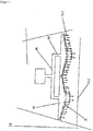
- Each of the tubes c) provided with openings f) is connected to a mixing device for mixing the components of the liquid starting material for the rigid isocyanate-based foam a). This is usually done by means of an intermediate feed d) and e). This is designed as a tube, in the case of using several tubes c) each is connected to the feed. This can be done through a tube, from which in turn connecting tubes to tubes c) originate.
- Figure 1 shows such a device with two tubes c).
- the diameter of the feeds d) is preferably constant. It is preferably 4 to 30 mm, particularly preferably 6 to 22 mm.
- the process described is suitable for all rigid isocyanate-based foams, such as polyurethane (PU) foams, and foams with urethane and isocyanurate groups, hereinafter also referred to as PUR / PIR foams or only as PIR foams.
- PU polyurethane
- PIR foams foams with urethane and isocyanurate groups
- a PIR foam is preferably used as the rigid foam based on isocyanate a).
- the process described is preferably designed such that the amount of the liquid starting material applied to the top layer b) for the rigid foam based on isocyanate a) is between 2 kg / min and 100 kg / min, preferably between 8 kg / min and 60 kg / min, is.
- the viscosity of the liquid starting material for the rigid isocyanate-based foam a) is preferably at 25 ° C. between 50 mPa * s and 2000 mPa * s, particularly preferably between 100 mPa * s and 1000 mPa * s.
- the method described is particularly suitable for foams with a low system start-up time.
- the start time of the systems used for the described method is preferably less than 15s, particularly less than 12s preferably less than 10s and especially less than 8s with a setting time of the system between 20 - 60 s.
- the start time is the time between the mixing of the polyol and isocyanate components and the start of the urethane reaction.
- the setting time is the time from mixing the starting components of the foams to the point in time at which the reaction product is no longer flowable. The setting time is adjusted depending on the element thickness produced and the double belt speed.
- an adhesion promoter can be applied between the cover layer b) and the rigid isocyanate-based foam a).
- the adhesion promoters known from the prior art can be used as adhesion promoters.
- polyurethanes are used, it being possible to use both reactive one-component and reactive two-component systems.
- the adhesion promoter is applied in the direction of movement of the cover layer b) in front of the pipe c) provided with holes.
- the distance between the application of the adhesion promoter and the application of the starting components for the rigid foam based on isocyanate a) should be selected so that the adhesion promoter has not yet fully reacted when the starting components for the rigid foam based on isocyanate based a) are applied.
- the adhesion promoter can be applied to the cover layer b) by known methods, for example by spraying.
- the adhesion promoter is preferably applied to the cover layer b) by means of a rotating flat disk which is attached horizontally or in a slight deviation from the horizontal of up to 15 °, preferably parallel to the cover layer b).
- the disk can be circular or elliptical and flat.
- the disk is preferably jagged or star-shaped, and the tips of the star can be bent upwards.
- the disc can be completely flat or rounded or beveled on the side upwards. It is preferred to use a disc which is rounded or bevelled upwards on the sides. Holes are made in the fold to ensure that the adhesion promoter is discharged. The diameter and number of holes are matched to one another in such a way that a finely divided hole is as uniform as possible Application of the adhesion promoter on the underlying cover layer b) is possible, all of the material applied to the pane can be discharged, and the maintenance effort for the pane is minimal.
- the disk is cascaded.
- the cascades are arranged rising from the axis of rotation to the outside. Holes can be made in the pane at the transitions from one to the adjacent cascade, so that part of the adhesion promoter can be discharged onto the lower cover layer b) at these cascade transitions.
- Such a cascade-shaped disk ensures a particularly uniform application of the adhesion promoter to the cover layer b) underneath.
- the adhesive agent is applied to the disc as close as possible to the axis of rotation. Surprisingly, it was found that the adhesion promoter is distributed particularly evenly over the lower cover layer b) if the application point of the adhesion promoter lies exactly in front of or behind the axis of rotation parallel to the production direction.
- the disk has a diameter between 0.05 to 0.3 m, preferably 0.1 to 0.25 m, particularly preferably 0.12 to 0.22 m, based on the long side , on. It is applied at a height of 0.02 to 0.2 m, preferably 0.03 to 0.18 m, particularly preferably 0.03 to 0.15 m, above the cover layer b) to be wetted.
- a disk with 2 to 4, preferably 2 to 3, particularly preferably 2, cascades can be used.
- Such an application device for the adhesion promoter is for example in WO 2006/029786 described.
- the described method and the described device are particularly suitable for systems with physical blowing agents, in particular pentanes. Furthermore, the method according to the invention is preferably suitable for the production of composite elements with rigid cover layers.
- cover layer b flexible or rigid, preferably rigid cover layers, such as plasterboard, glass tile, aluminum foils, aluminum, copper or steel sheets, preferably aluminum foils, aluminum or steel sheets, particularly preferably steel sheets, can be used as cover layer b) be used.
- the steel sheets can be coated or uncoated.
- the steel sheets can be pretreated, for example with corona, arc, plasma treatment or other conventional methods.
- the cover layer b) is preferably transported at a constant speed of 1 to 60 m / min, preferably 2 to 150 m / min, particularly preferably 2.5 to 30 m / min and in particular 2.5 to 20 m / min.
- the cover layer b) is at least in a horizontal position from the application of the foam system b), preferably for the entire period from the application of the adhesion promoter.
- the cover layers are successively decoiled from a roll, optionally profiled, heated, optionally pretreated in order to increase the foamability with polyurethane, optionally with the adhesion promoter applied, with the starting material for the rigid foam Isocyanate base a) foamed using the standing rake described, cured in a double belt and finally cut to the desired length.
- the rigid foams based on isocyanate a) used for the process described are produced in a customary and known manner by reacting polyisocyanates with compounds having at least two hydrogen atoms reactive with isocyanate groups in the presence of blowing agents, catalysts and customary auxiliaries and / or additives.
- blowing agents, catalysts and customary auxiliaries and / or additives The following can be said in detail about the starting materials used.
- Suitable organic polyisocyanates are all known organic di- and polyisocyanates, preferably aromatic polyvalent isocyanates.
- Examples include 2,4- and 2,6-tolylene diisocyanate (TDI) and the corresponding isomer mixtures, 4,4'-, 2,4'- and 2,2'-diphenylmethane diisocyanate (MDI) and corresponding mixtures of isomers, mixtures of 4,4'- and 2,4'-diphenylmethane diisocyanates, polyphenyl polymethylene polyisocyanates, mixtures of 4,4'-, 2,4'- and 2,2'-diphenylmethane diisocyanates and polyphenyl polymethylene polyisocyanates (crude MDI) and mixtures of crude MDI and tolylene diisocyanates.
- the organic di- and polyisocyanates can be used individually or in the form of mixtures.
- modified polyvalent isocyanates i.e. Products obtained by chemical conversion of organic di- and / or polyisocyanates are used. Examples include uretdione, carbamate, isocyanurate, carbodiimide, allophanate and / or urethane groups containing di- and / or polyisocyanates.
- the modified polyisocyanates can optionally be combined with one another or with unmodified organic polyisocyanates such as e.g. 2,4'-, 4,4'-diphenylmethane diisocyanate, crude MDI, 2,4- and / or 2,6-tolylene diisocyanate can be mixed.
- reaction products of polyvalent isocyanates with polyvalent polyols and their mixtures with other di- and polyisocyanates can also be used.
- Raw MDI has proven particularly useful as an organic polyisocyanate, in particular with an NCO content of 29 to 33% by weight and a viscosity at 25 ° C. in the range from 150 to 1000 mPas.
- Suitable compounds with at least two hydrogen atoms reactive toward isocyanate groups are those which carry at least two reactive groups, selected from OH groups, SH groups, NH groups, NH 2 groups and CHacid groups, preferably OH groups, and in particular polyether alcohols and / or polyester alcohols with OH numbers in the range from 25 to 800 mg KOH / g are used.
- the polyester alcohols used are usually obtained by condensation of polyfunctional alcohols, preferably diols, with 2 to 12 carbon atoms, preferably 2 to 6 carbon atoms, with polyfunctional carboxylic acids with 2 to 12 carbon atoms, for example succinic acid, glutaric acid, adipic acid, suberic acid, azelaic acid, sebacic acid, decanedicarboxylic acid, Maleic acid, fumaric acid and preferably phthalic acid, isophthalic acid, terephthalic acid and the isomeric naphthalenedicarboxylic acids.
- the polyesterols used mostly have a functionality of 1.5 - 4.
- polyether polyols which are prepared by known processes, for example by anionic polymerization of alkylene oxides on H-functional starters in the presence of catalysts, preferably alkali metal hydroxides or double metal cyanide catalysts (DMC catalysts), are used.
- catalysts preferably alkali metal hydroxides or double metal cyanide catalysts (DMC catalysts).
- the alkylene oxides used are mostly ethylene oxide or propylene oxide, but also tetrahydrofuran, various butylene oxides, styrene oxide, preferably pure 1,2-propylene oxide.
- the alkylene oxides can be used individually, alternately in succession or as mixtures.
- starter substances with at least 2, preferably 2 to 8 hydroxyl groups in the molecule, trimethylolpropane, glycerol, pentaerythritol, sugar compounds such as, for example, glucose, sorbitol, mannitol and sucrose, polyhydric phenols, resols, such as e.g. oligomeric condensation products from phenol and formaldehyde and Mannich condensates from phenols, formaldehyde and dialkanolamines and melamine.
- sugar compounds such as, for example, glucose, sorbitol, mannitol and sucrose
- polyhydric phenols such as e.g. oligomeric condensation products from phenol and formaldehyde and Mannich condensates from phenols, formaldehyde and dialkanolamines and melamine.
- Aromatic di- and / or polyamines for example phenylenediamines, 2,3-, 2,4-, 3,4- and 2,6-toluenediamine and 4,4'-, 2nd, are preferably used as starter substances with at least two primary amino groups in the molecule , 4'- and 2,2'-diaminodiphenylmethane and aliphatic di- and polyamines, such as ethylenediamine, are used.
- the polyether polyols have a functionality of preferably 2 to 8 and hydroxyl numbers of preferably 25 mg KOH / g to 800 mg KOH / g and in particular 150 mg KOH / g to 570 mg KOH / g.
- the compounds with at least two hydrogen atoms reactive toward isocyanate also include the chain extenders and crosslinking agents which may be used.
- chain extenders and crosslinking agents which may be used.
- difunctional chain extenders, trifunctional and higher-functional crosslinking agents or, if appropriate, mixtures thereof can prove to be advantageous.
- the chain extenders and / or crosslinking agents used are preferably alkanolamines and in particular diols and / or triols with molecular weights of less than 400, preferably 60 to 300.
- Chain extenders, crosslinking agents or mixtures thereof are advantageously used in an amount of 1 to 20% by weight, preferably 2 to 5% by weight, based on the polyol component.
- the rigid foams are usually produced in the presence of blowing agents, catalysts, flame retardants and cell stabilizers and, if necessary, other auxiliaries and / or additives.
- Chemical blowing agents such as water and / or formic acid can be used as blowing agents, which react with isocyanate groups with the elimination of carbon dioxide or carbon dioxide and carbon monoxide.
- So-called physical blowing agents can preferably also be used in combination with or preferably instead of water. These are compounds which are inert to the feed components and are mostly liquid at room temperature and evaporate under the conditions of the urethane reaction. The boiling point of these compounds is preferably below 50.degree.
- the physical blowing agents also include compounds which are gaseous at room temperature and are introduced or dissolved in the feed components under pressure, for example carbon dioxide, low-boiling alkanes and fluoroalkanes.
- the blowing agents are mostly selected from the group consisting of formic acid, alkanes and / or cycloalkanes with at least 4 carbon atoms, dialkyl ethers, esters, ketones, acetals, fluoroalkanes with 1 to 8 carbon atoms, and tetraalkylsilanes with 1 to 3 carbon atoms in the alkyl chain, in particular tetramethylsilane .
- Examples include propane, n-butane, iso- and cyclobutane, n-, iso- and cyclopentane, cyclohexane, dimethyl ether, methyl ethyl ether, methyl butyl ether, methyl formate, acetone, and fluoroalkanes, which can be broken down in the troposphere and are therefore harmless to the ozone layer such as trifluoromethane, difluoromethane, 1,1,1,3,3-pentafluorobutane, 1,1,1,3,3-pentafluoropropane, 1,1,1,2-tetrafluoroethane, difluoroethane and heptafluoropropane.
- the physical blowing agents mentioned can be used alone or in any combination with one another.
- a mixture of formic acid, water and pentane is particularly preferred as the blowing agent mixture.
- the blowing agent component is usually present in an amount of 1 to 45% by weight, preferably 1 to 30% by weight, particularly preferably 1.5 to 20% by weight and in particular 2 to 15% by weight, based on the total weight of the components polyol, blowing agent, catalyst system, and possibly foam stabilizers, flame retardants and other additives.
- the polyurethane or polyisocyanurate foams usually contain flame retardants. Bromine-free flame retardants are preferably used. Flame retardants containing phosphorus atoms are particularly preferred, in particular trischloroisopropyl phosphate, diethyl ethane phosphonate, triethyl phosphate and / or diphenyl cresyl phosphate are used.
- catalysts Compounds which accelerate the reaction of the isocyanate groups with the groups reactive with isocyanate groups are used in particular as catalysts.
- catalysts are basic amines, such as secondary aliphatic amines, imidazoles, amidines, alkanolamines, Lewis acids or organometallic compounds, in particular those based on tin. Catalyst systems consisting of a mixture of different catalysts can also be used.
- isocyanurate groups are to be incorporated into the rigid foam, special catalysts are required.
- Metal carboxylates in particular potassium acetate and its solutions, are usually used as isocyanurate catalysts.
- the catalysts can be used alone or in any mixtures with one another.
- Auxiliaries and / or additives are the substances known per se for this purpose, for example surface-active substances, foam stabilizers, cell regulators, fillers, pigments, dyes, antioxidants, hydrolysis stabilizers, antistatic agents, fungistatic and bacteriostatic agents.
- the polyisocyanates and the compounds having at least two hydrogen atoms reactive with isocyanate groups are reacted in such amounts that the isocyanate index in the case of the polyurethane foams is in a range between 100 and 220, preferably between 115 and 180 , lies.
- An index of> 180 generally 180 to 700, preferably 200 to 550, particularly preferably 250 to 500 and in particular 270 to 400 can also be used in the production of polyisocyanurate foams.
- the rigid polyurethane foams can be produced batchwise or continuously using known mixing devices.
- the starting components can be mixed with the aid of known mixing devices.
- the isocyanate-based rigid foams described a) are usually produced by the two-component process.
- the compounds with at least two hydrogen atoms which are reactive toward isocyanate groups are mixed with the blowing agents, the catalysts and the further auxiliaries and / or additives to form a so-called polyol component and this with the polyisocyanates or mixtures of the polyisocyanates and optionally blowing agents, also as the isocyanate component referred to, implemented.
- the starting components are usually mixed at a temperature of 15 to 35 ° C, preferably 20 to 30 ° C.
- the reaction mixture can be mixed with high or low pressure metering machines.
- the density of the rigid foams produced is preferably 10 to 400 kg / m3, preferably 20 to 200, in particular 30 to 100 kg / m3.
- the thickness of the composite elements is usually in the range between 5 to 250 mm.
- Polyol component (A component) 44 pieces Polyetherol 1 consisting of propylene oxide and an aminic starter, functionality 4, hydroxyl number 400 mg KOH / g 26 part Polyetherol 2 consisting of propylene oxide and sucrose as starter, OHZ 400 mg KOH / g 5 parts Polyetherol 3 consisting of propylene oxide and trimethylolpropane as starter, OHZ 200 mg KOH / g 20 parts Flame retardant 1 trischloroisopropyl phosphate, TCPP 2 parts Stabilizer containing silicon 2 parts Catalyst 1 amine-containing PUR catalyst 1st chapter Catalyst 2 amine-containing blowing catalyst Blowing agent 1 n-pentane Blowing agent 2 water Blowing agent 3 aqueous formic acid, 85%
- Isocyanate Lupranat M50 polymeric MDI (BASF AG), NCO content 31%, viscosity 500 mPas at 25 ° C.
- A, B component and blowing agent were reacted in such proportions that the index was in the range 130 and a bulk density of 39 g / L was reached.
- Polyol component (A component) 66 parts Polyesterol 1 consisting of phthalic anhydride, diethylene glycol and oleic acid, functionality 1.8, hydroxyl number 200 mg KOH / g 30 parts Flame retardant 1 Trischloroisopropyl phosphate, TCPP 1.5 parts Stabilizer 1 Stabilizer containing silicon 1.5 parts Catalyst 1 PIR catalyst, salt of a carboxylic acid 1st chapter Catalyst 2 amine-containing PUR catalyst Blowing agent 1 n-pentane Blowing agent 2 water Blowing agent 3 aqueous formic acid, 85%
- Isocyanate Lupranat M50 polymeric MDI (BASF AG), NCO content 31%, viscosity 500 mPas at 25 ° C.
- the polyol and isocyanate components and the blowing agent were mixed with one another in such proportions that the characteristic number was in the region of 350 and a bulk density of 43 g / L was achieved.
- the polyurethane or polyisocyanurate system a) was applied in succession by means of an oscillating pouring rake and a standing pouring rake consisting of two tubes c) of equal length arranged in a row.
- the oscillating casting rake had the dimensions 25 cm x 1.5 cm, had 41 holes with a diameter of 1.6 mm and a hole spacing of 5 mm and oscillated at a speed of 0.7 m / s over a distance of 1.0 m.
- the standing rake had the dimensions 95 cm x 15 cm, had 24 holes with a diameter of 2.8 mm and a hole spacing of 40 mm.
- the hole lengths of the openings f) for each of the two tubes c) increased exponentially from the edge to the center, starting from 3 mm to 19 mm.
- the application rate for both rake systems was 25.1 kg / min.
- the metallic top layer was not corona treated.
- the double belt had a width of 1.2 m and was driven at a constant speed of 5.0 m / min.
- the temperature of the sheet was 37 ° C, that of the double strip was set to 40 ° C (PUR) or 60 ° C (PIR).
- the sandwich element thickness was 100 mm.
- test specimens measuring 100x100x5 mm were sawn and the adhesion of the foam to the top layer was determined in accordance with DIN EN ISO 527-1 / DIN 53292.
- the frequency of surface defects was quantified by an optical method.
- the polyurethane reaction solution was applied at a distance of one millimeter to the lower cover layer, i.e. the cover layer, using the double-belt process was applied, a level was placed in a foam sample and the excess material was separated off.
- the foam surface thus obtained was illuminated at an opening angle of 5 ° and the area of the shadow cast by surface defects in relation to the entire surface. To do this, the illuminated foam surface was photographed and the foam images were then binarized.
- the integrated area of the black areas of the binary images was set in relation to the total area of the images and thus represents a measure of the frequency of surface defects.
- an additional qualitative assessment of the surface properties of the foams was carried out, the top layer being 1 mx 2 m large foam sample was removed and the surface was visually assessed.
- Table 1 show that the frequency of the formation of surface defects at the interface with metallic cover layers is significantly reduced by the use of the standing casting rake described compared to the prior art, and the mechanical properties of the foam and the adhesion between hard foam and cover layer are improved .
Landscapes
- Engineering & Computer Science (AREA)
- Mechanical Engineering (AREA)
- Robotics (AREA)
- Chemical & Material Sciences (AREA)
- Wood Science & Technology (AREA)
- Materials Engineering (AREA)
- Life Sciences & Earth Sciences (AREA)
- Organic Chemistry (AREA)
- Manufacturing & Machinery (AREA)
- Polyurethanes Or Polyureas (AREA)
- Laminated Bodies (AREA)
- Casting Or Compression Moulding Of Plastics Or The Like (AREA)
- Manufacture Of Porous Articles, And Recovery And Treatment Of Waste Products (AREA)
- Application Of Or Painting With Fluid Materials (AREA)
Description
Die Erfindung betrifft ein Verfahren zur Herstellung von Verbundelementen aus mindestens einer Deckschicht und einem schaumbildenden Reaktionsgemisch, welches über mindestens ein feststehendes, mit Öffnungen versehenes Rohr auf die untere Deckschicht aufgetragen wird.The invention relates to a method for producing composite elements from at least one cover layer and a foam-forming reaction mixture, which is applied to the lower cover layer via at least one fixed tube provided with openings.
Die Herstellung von Verbundelementen aus insbesondere metallischen Deckschichten und einem Kern aus Schaumstoffen auf Isocyanatbasis, zumeist Polyurethan-(PUR) oder Polyisocyanurat-(PIR) Schaumstoffen, häufig auch als Sandwichelemente bezeichnet, auf kontinuierlich arbeitenden Doppelbandanlagen wird gegenwärtig in großem Umfang praktiziert. Neben Sandwichelementen zur Kühlhausisolierung gewinnen Elemente zur Gestaltung von Fassaden verschiedenster Gebäude immer mehr an Bedeutung. Als Deckschichten werden dabei neben beschichteten Stahlblechen auch Edelstahl-, Kupfer- oder Aluminiumbleche eingesetzt. Insbesondere bei den Fassadenelementen spielt die Oberflächenstruktur der Schaumgrenze zur Deckschicht eine entscheidende Rolle. Aus verschiedensten Gründen kommt es bei der Herstellung der Sandwichelemente oftmals zu unerwünschten Lufteinschlüssen zwischen der unteren Deckschicht und dem Schaumstoff auf Isocyanatbasis, sogenannten Lunkern. Diese Lufteinschlüsse zwischen Blech und Schaumstoff können besonders bei starken Temperaturwechseln und dunklen Farbtönen der Deckschicht in der Anwendung als Fassadenelement zu Ausbeulungen des Bleches führen und die Fassade unansehnlich machen.The production of composite elements from in particular metallic cover layers and a core made of foams based on isocyanate, mostly polyurethane (PUR) or polyisocyanurate (PIR) foams, often also referred to as sandwich elements, is currently practiced on a large scale on continuously operating double belt systems. In addition to sandwich elements for cold store insulation, elements for the design of facades in a wide variety of buildings are becoming increasingly important. In addition to coated steel sheets, stainless steel, copper or aluminum sheets are also used as cover layers. In the case of facade elements in particular, the surface structure of the foam boundary to the top layer plays a decisive role. For a variety of reasons, undesirable air pockets between the lower cover layer and the isocyanate-based foam, so-called cavities, often occur in the manufacture of the sandwich elements. These air pockets between sheet metal and foam, particularly when there are strong temperature changes and dark shades of the top layer when used as a facade element, can cause the sheet to bulge and make the facade unsightly.
Weiterhin wird die Haftung zwischen Isolierschaum und unterer Deckschicht vermindert. Oftmals ist es so, dass bei Sandwichelementen die untere Deckschicht die schlechteste Haftung, bestimmt beim Zugversuch, aufweist. Weiterhin ist bei den üblichen mittels Sandwichelementen erstellten Konstruktionen die Blechunterseite die Außenseite der Fassade, sodass sie extremen Bedingungen wie Temperatur und Sogwirkungen ausgesetzt ist und deswegen stärker belastet wird als die Oberseite des Sandwichelementes, was zur Schaumablösung vom Blech und somit ebenfalls zu Ausbeulungen führen kann.Furthermore, the adhesion between the insulating foam and the lower cover layer is reduced. It is often the case that the lower covering layer has the worst adhesion, determined during tensile tests, in sandwich elements. Furthermore, in the case of the usual constructions created using sandwich elements, the underside of the sheet metal is the outside of the facade, so that it is exposed to extreme conditions such as temperature and suction effects and is therefore subjected to a greater load than the top side of the sandwich element, which can lead to foam detachment from the sheet metal and thus also to bulges.
Demzufolge ist es erforderlich, ein Verfahren zu finden, welches die Lunkerbildung an der Oberfläche der Hartschaumstoffe auf Isocyanatbasis nachhaltig minimiert oder ganz vermeidet und auch bei widrigen äußeren Umständen des Produktionsverfahrens funktioniert. Das Verfahren soll kontinuierlich oder diskontinuierlich eingesetzt werden können. Eine diskontinuierliche Arbeitsweise kann zum Beispiel bei Anfahrvorgängen des Doppelbandes und bei mittels diskontinuierlich arbeitenden Pressen hergestellten Verbundelementen in Frage kommen. Eine kontinuierliche Anwendung erfolgt beim Einsatz von Doppelbandanlagen.Accordingly, it is necessary to find a process which sustainably minimizes or completely avoids the formation of voids on the surface of the rigid isocyanate-based foams and which also functions under adverse external circumstances of the production process. The process should be able to be used continuously or batchwise. A discontinuous mode of operation can be considered, for example, when starting up the double belt and in the case of composite elements produced using discontinuously operating presses. A continuous application takes place when using double belt systems.
Das Reaktionsgemisch wird beim Doppelbandverfahren nach dem Stand der Technik maschinell mit Hoch- oder Niederdrucktechnik hergestellt und mittels oszillierenden Gießharken auf die untere Deckschicht aufgetragen. Dabei steht die Harke in Bandlaufrichtung und oszilliert über die Elementbreite. Nachteilig dieser Auftragungsart ist, dass bei einer erforderlichen Doppelüberlappung auf bereits aufgetragenes Reaktionsgemisch neues Material aufgetragen wird, so dass ein Gemisch mit unterschiedlichen Reaktionszuständen vorliegt. Letzteres führt dazu, dass die daraus resultierende Schaumoberfläche nicht gleichmäßig aufsteigt und als Folge beim Zuführen der oberen Deckschicht Luft mit eingeschlossen wird. Dieser Nachteil ist umso deutlicher je geringer die Zeit zwischen dem Reaktionsgemischauftrag und dem Start der Schäumreaktion ist. Die Geschwindigkeit des kontinuierlich arbeitenden Doppelbandes wird durch die maximal mögliche Oszillationsgeschwindigkeit des Mischkopfes begrenzt. Zusätzlich wirkt sich nachteilig aus, dass mit zunehmender Oszillation mehr Reaktionsgemisch im Randbereich und weniger im Mittenbereich der Deckschicht aufgetragen wird.In the double belt process according to the prior art, the reaction mixture is produced mechanically using high or low pressure technology and applied to the lower cover layer by means of oscillating casting rakes. The rake stands in the belt running direction and oscillates across the element width. The disadvantage of this type of application is that when a double overlap is required, new material is applied to the already applied reaction mixture, so that a mixture with different reaction states is present. The latter means that the resulting foam surface does not rise evenly and, as a result, air is trapped when the upper cover layer is supplied. This disadvantage is all the clearer the shorter the time between the application of the reaction mixture and the start of the foaming reaction. The speed of the continuously operating double belt is limited by the maximum possible oscillation speed of the mixing head. In addition, it has the disadvantage that, with increasing oscillation, more reaction mixture is applied in the edge area and less in the middle area of the cover layer.
Im alternativen Schnellläuferverfahren wird das Reaktionsgemisch über einen Mehrfingerauftrag auf die untere Deckschicht aufgebracht, wobei ebenfalls Luftblasen im Reaktionsgemisch eingeschlossen werden und sich somit ebenfalls nur Lunker behaftete Oberflächen herstellen lassen. Zusätzlich muss das Reaktionsgemisch bei dieser Art des Auftrags über größere Bereiche seitlich "verfließen", so dass vor allem in den äußersten Bereichen, bevor die einzelnen Stränge des Mehrfingerauftrags ineinander laufen, größere Lunkerzonen auf der unteren und oberen Deckschicht entstehen. Weiterhin ist in dem Bereich, in welchem die Stränge des Mehrfingerauftrags ineinander fließen, häufig eine Riefe, zumindest jedoch eine Schaumstörung zu erkennen.In the alternative high-speed process, the reaction mixture is applied to the lower cover layer by means of a multi-finger application, air bubbles also being included in the reaction mixture and thus only voids-affected surfaces can be produced. In addition, with this type of application, the reaction mixture has to "flow away" laterally over larger areas, so that, especially in the outermost areas, before the individual strands of the multi-finger application run into one another, larger blowholes zones are formed on the lower and upper cover layers. Furthermore, in the area in which the strands of the multi-finger application flow into one another, a scoring, or at least a foam disturbance, can often be seen.
Zur Behebung dieser Mängel wird in
Aufgabe der vorliegenden Erfindung war es nun, ein Auftragsverfahren für ein Reaktionsgemisch eines Hartschaumstoffes auf Isocyanatbasis, insbesondere ein PUR- oder PIR-System, auf ein horizontales Blech oder eine andere flexible oder starre Deckschicht zu finden, die in horizontaler Richtung kontinuierlich transportiert wird, wie es für die Herstellung von Sandwichelementen mit einem kontinuierlich arbeitenden Doppelband üblich ist. Dabei sollte es zu einer gegenüber dem Stand der Technik verbesserten Oberflächenstruktur des Schaums an der unteren Deckschicht, und insbesondere zu einer Vermeidung von Lunkern, kommen. Weiterhin sollte das Verfahren zu einer besseren Haftung zwischen Deckschicht und Hartschaum führen. Insbesondere sollte die Oberfläche des aufgetragenen Schaums gleichmäßig sein. Das Verfahren sollte vor allem für schnell startende Systeme geeignet sein, wobei die oben aufgeführten Nachteile des Mehrfingerauftrags und des oszillierenden Harken-Auftrags vermieden werden sollten.It was an object of the present invention to find an application method for a reaction mixture of a rigid foam based on isocyanate, in particular a PUR or PIR system, on a horizontal plate or another flexible or rigid cover layer, which is transported continuously in the horizontal direction, such as it is common for the production of sandwich elements with a continuously working double belt. This should result in an improved surface structure of the foam on the lower cover layer compared to the prior art, and in particular the avoidance of cavities. The process should also lead to better adhesion between the top layer and rigid foam. In particular, the surface of the applied foam should be even. The method should be particularly suitable for fast starting systems, whereby the disadvantages of the multi-finger application and the oscillating Harken application listed above should be avoided.
Die Aufgabe konnte überraschenderweise gelöst werden, indem das Reaktionsgemisch mittels mindestens eines feststehenden, parallel und rechtwinklig zur Bewegungsrichtung zur Deckschicht b) angebrachten, mit Bohrungen versehenen Rohres c), im Folgenden auch als Gießharke bezeichnet, auf die untere Deckschicht b) aufgetragen wird.Surprisingly, the object was achieved by applying the reaction mixture to the lower cover layer b) by means of at least one fixed tube c), which is provided parallel to and perpendicular to the direction of movement to the cover layer b) and is also referred to below as a pouring rake.
Gegenstand der Erfindung ist eine Verwendung von Rohren für den Auftrag von flüssigen Ausgangsmaterialien für Hartschaumstoff auf Isocyanatbasis auf eine sich kontinuierlich bewegende Deckschicht bei der Herstellung von Verbundkörpern, wobei die Rohre Öffnungen mit einem Durchmesser und einer Länge aufweisen, wobei die Länge der Öffnungen von der Mitte eines Rohres zu dessen Enden hin abnimmt und die Zuführung des flüssigen Ausgangsmaterials für Hartschaumstoff auf Isocyanatbasis in der Mitte des Rohres erfolgt.The invention relates to the use of pipes for the application of liquid starting materials for rigid isocyanate-based foam to a continuously moving top layer in the production of composite bodies, the pipes having openings with a diameter and a length, the length of the openings being from the center a tube decreases towards the ends and the supply of the liquid starting material for rigid foam based on isocyanate takes place in the middle of the tube.
Offenbart ist auch ein Verfahren zur Herstellung von Verbundkörpern, bestehend aus mindestens einer Deckschicht b) und einem Hartschaumstoff auf Isocyanatbasis a), wobei die Deckschicht b) kontinuierlich bewegt wird und das Ausgangsmaterial für den Hartschaumstoff auf Isocyanatbasis a) auf die Deckschicht b) aufgebracht wird, dadurch gekennzeichnet, dass der Auftrag des flüssigen Ausgangsmaterials für den Hartschaumstoff auf Isocyanatbasis a) mittels mindestens einem feststehenden, parallel zur Deckschichtenebene und rechtwinklig zur Bewegungsrichtung zur Deckschicht b) angebrachten, mit Öffnungen f) versehenen Rohre c) erfolgt.Also disclosed is a process for the production of composite bodies consisting of at least one cover layer b) and a rigid foam based on isocyanate a), the cover layer b) being moved continuously and the starting material for the rigid foam based on isocyanate a) being applied to the cover layer b) , characterized in that the application of the liquid starting material for the rigid isocyanate-based foam a) takes place by means of at least one fixed pipe c) provided with openings f) and parallel to the plane of the cover layer and perpendicular to the direction of movement to the cover layer b).
Die Begriffe Löcher und Bohrungen können im Folgenden synonym verwendet werden. Offenbart ist weiterhin eine Vorrichtung zum Auftrag von flüssigen Reaktionsgemischen auf eine Deckschicht b) und wobei die Deckschicht b) kontinuierlich bewegt wird und das Ausgangsmaterial für den Hartschaumstoff auf Isocyanatbasis a) auf die Deckschicht b) aufgebracht wird, dadurch gekennzeichnet, dass der Auftrag des flüssigen Reaktionsgemisches auf die Deckschicht b) mittels mindestens zwei nebeneinander angeordneter, feststehender, parallel zur Deckschichtenebene und rechtwinklig zur Bewegungsrichtung der Deckschicht b) angebrachten, mit Öffnungen f) versehener Rohre c) erfolgt.The terms holes and bores can be used synonymously below. Also disclosed is a device for applying liquid reaction mixtures to a cover layer b) and wherein the cover layer b) is moved continuously and the starting material for the rigid foam based on isocyanate a) is applied to the cover layer b), characterized in that the application of the liquid Reaction mixture on the cover layer b) is carried out by means of at least two fixed tubes c) which are arranged next to one another and are arranged parallel to the plane of the cover layer and at right angles to the direction of movement of the cover layer b) and have openings f).
Vorzugsweise werden mindestens zwei mit Öffnungen f) versehene Rohre c) insbesondere so angeordnet, dass sie eine gerade Linie bilden. Vorzugsweise werden 2 bis 4, besonders bevorzugt 2 bis 3 und insbesondere 2 Rohre c) verwendet.Preferably, at least two pipes c) provided with openings f) are in particular arranged such that they form a straight line. Preferably 2 to 4, particularly preferably 2 to 3 and in particular 2 tubes c) are used.
Die Gießharke besitzt, wie beschrieben, eine rohrähnliche Form, mit Löchern an der Unterseite, verteilt über die gesamte Länge, und der Zufuhr des Reaktionsgemisches entweder an einem Ende der Rohre c)oder vorzugsweise in deren Mitte sitzend. Bei Verwendung mehrerer Rohre c) wird die Zuführung vorzugsweise bei allen Rohren c) in der gleichen Weise vorgenommen.As described, the casting rake has a tube-like shape, with holes on the underside, distributed over the entire length, and the feed of the reaction mixture either at one end of the tubes c) or preferably sitting in the middle thereof. If several tubes c) are used, the supply is preferably carried out in the same way for all tubes c).
Die Rohre c) beziehungsweise die nebeneinander angeordneten Rohre c)zusammen können eine Länge haben, die gleich der Breite der Deckschicht b) ist. Vorzugsweise ist die Länge des Rohres c) geringer als die Breite der Deckschicht b), um sicherzustellen, dass die Reaktionsmischung nicht teilweise neben die Deckschicht b) aufgetragen wird. Dabei ist die Gießharke mittig über der Deckschicht b) angeordnet. Vorzugsweise bedeckt die Gießharke mindestens 70 % der Breite der Deckschicht b). Bei einer Breite der Deckschicht b) von 1,20 m, wie sie bei Sandwich-Elementen üblich ist, wäre in diesem Fall auf jeder Seite eine Breite von 25 cm nicht von der Gießharke bedeckt. Vorzugsweise bedecken die Gießharke beziehungsweise die nebeneinander angeordneten Gießharken mindestens 70 %, besonders bevorzugt mindestens 80 %, und insbesondere mindestens 95 % der Breite der Deckschicht b).The tubes c) or the tubes c) arranged side by side together can have a length that is equal to the width of the cover layer b). The length of the tube c) is preferably less than the width of the cover layer b) in order to ensure that the reaction mixture is not partially applied next to the cover layer b). The pouring rake is arranged centrally above the cover layer b). The casting rake preferably covers at least 70% of the width of the covering layer b). With a width of the cover layer b) of 1.20 m, as is common with sandwich elements, a width of 25 cm would not be covered by the pouring rake on each side in this case. The casting rake or the casting rakes arranged next to one another preferably cover at least 70%, particularly preferably at least 80%, and in particular at least 95% of the width of the covering layer b).
Die Harke ist üblicherweise in einer Höhe zur unteren Deckschicht b) von 5 bis 30 cm, bevorzugt 10 bis 30 cm, und insbesondere 15 bis 25 cm, angebracht.The rake is usually attached at a height to the lower cover layer b) of 5 to 30 cm, preferably 10 to 30 cm, and in particular 15 to 25 cm.
Die Anzahl der Öffnungen f) entlang der Harke beträgt je nach Harkenlänge mindestens 2, bevorzugt mindestens 6, besonders bevorzugt 10 bis 50, und insbesondere 20 bis 40. Vorzugsweise ist die Anzahl der Löcher eine gerade Zahl.Depending on the length of the rake, the number of openings f) along the rake is at least 2, preferably at least 6, particularly preferably 10 to 50, and in particular 20 to 40. The number of holes is preferably an even number.
Die Durchmesser der Öffnungen f) liegen im Bereich von 0,5 bis 10 mm, bevorzugt 1,0 mm bis 4 mm. Die Abständen der Öffnungen f) voneinander betragen vorzugsweise 5-200 mm, besonders bevorzugt 5 bis 60 mm, und insbesondere 10 bis 30 mm. Vorzugsweise ist der Abstand und der Durchmesser über die gesamte Länge des Rohres c) gleich.The diameters of the openings f) are in the range from 0.5 to 10 mm, preferably 1.0 mm to 4 mm. The distances between the openings f) are preferably 5-200 mm, particularly preferably 5 to 60 mm, and in particular 10 to 30 mm. The distance and the diameter are preferably the same over the entire length of the tube c).
Das Rohr c) hat einen Innendurchmesser von 0,2 bis 5 cm, bevorzugt 0,3 bis 2,5 cm und insbesondere 0,2 bis 2 cm.The tube c) has an inner diameter of 0.2 to 5 cm, preferably 0.3 to 2.5 cm and in particular 0.2 to 2 cm.
Gemäß der Erfindung ist die Länge der Öffnungen f) über die Länge des Rohres c) unterschiedlich. Unter der Länge der Öffnungen f) ist die Entfernung zu verstehen, die das Gemisch a) vom Inneren des Rohres c) bis zum Austritt aus dem Rohr c) zurücklegen muss. Dies kann auf unterschiedliche Weise geschehen. Zum einen kann der Innendurchmesser des Rohres c) verändert werden. Dies ist nicht bevorzugt, da derartige Bauteile schwierig herzustellen und zu säubern sind.According to the invention, the length of the openings f) is different over the length of the tube c). The length of the openings f) is to be understood as the distance which the mixture a) has to travel from the inside of the tube c) to the outlet from the tube c). This can be done in different ways. On the one hand, the inside diameter of the tube c) can be changed. This is not preferred because such components are difficult to manufacture and clean.
Vorzugsweise wird die Länge der Öffnungen f) verändert, indem an der Unterseite des Rohres c) ein Metallteil so angebracht wird, dass die Länge der Bohrungen in der gewünschten Weise verändert wird. Durch diese Maßnahme wird faktisch die Wandstärke des Rohres c) geändert. Die Lochlängen, betrachtet von dem Ort der Zuführung des Ausgangsmaterials für den Hartschaumstoff auf Isocyanatbasis a) bis zum Ende, verringern sich nicht linear, sondern exponentiell. Gemäß der Erfindung erfolgt die Verlängerung der Öffnungen f) dergestalt, dass die Länge von der Zuführung des Gemisches a) zu den Enden des Rohres c) hin abnimmt. Das heißt, dass bei der Zuführung des Gemisches a) in der Mitte des Rohres c) die Länge der Öffnungen f) zu den Rändern hin abnimmt.The length of the openings f) is preferably changed by attaching a metal part to the underside of the tube c) in such a way that the length of the bores is changed in the desired manner. This measure effectively changes the wall thickness of the tube c). The hole lengths, viewed from the point at which the starting material for the rigid isocyanate-based foam a) is fed, to the end, do not decrease linearly, but exponentially. According to the invention, the openings f) are lengthened in such a way that the length decreases from the supply of the mixture a) to the ends of the tube c). This means that when the mixture a) is fed in the middle of the tube c) the length of the openings f) decreases towards the edges.
Die Länge der Öffnungen f) ist dabei vorzugsweise so zu wählen, dass das Verhältnis der Länge der Öffnungen f) vom Rand zur Mitte für jedes Rohr c) zwischen 1,1 und 10 beträgt. Besonders bevorzugt liegt das Verhältnis zwischen 2,5 und 10, insbesondere zwischen 5 und 10The length of the openings f) should preferably be chosen such that the ratio of the length of the openings f) from the edge to the center for each tube c) is between 1.1 and 10 is. The ratio is particularly preferably between 2.5 and 10, in particular between 5 and 10
Wenn mehrere Rohre c) verwendet werden, wird die Variation der Länge der Öffnungen f) für alle Rohre c) gleich ausgestaltet.If several tubes c) are used, the variation in the length of the openings f) is made the same for all tubes c).
Jedes der mit Öffnungen f) versehenen Rohre c) ist mit einer Mischeinrichtung für die Mischung der Komponenten des flüssigen Ausgangsmaterials für den Hartschaumstoff auf Isocyanatbasis a) verbunden. Dies erfolgt üblicherweise mittels einer dazwischen liegenden Zuführung d) und e). Diese ist als Rohr ausgestaltet, im Falle der Verwendung von mehreren Rohren c) ist jedes mit der Zuführung verbunden. Dies kann durch ein .Rohr geschehen, von dem wiederum Verbindungsrohre zu den Rohren c) ausgehen.
Der Durchmesser der Zuführungen d) ist vorzugsweise konstant. Er beträgt vorzugsweise 4 bis 30 mm, besonders bevorzugt 6 bis 22 mm.The diameter of the feeds d) is preferably constant. It is preferably 4 to 30 mm, particularly preferably 6 to 22 mm.
Das beschriebene Verfahren ist geeignet für alle Hartschaumstoffe auf Isocyanatbasis, wie Polyurethan(PU)-Schäume, und Schäume mit Urethan- und Isocyanuratgruppen, im Folgenden auch als PUR/PIR-Schäume oder nur als PIR-Schäume bezeichnet. Für viele Anwendungen der nach dem beschriebenen Verfahren hergestellten Verbundkörper wird als Hartschaumstoff auf Isocyanatbasis a) bevorzugt ein PIR-Schaum eingesetzt.The process described is suitable for all rigid isocyanate-based foams, such as polyurethane (PU) foams, and foams with urethane and isocyanurate groups, hereinafter also referred to as PUR / PIR foams or only as PIR foams. For many applications of the composite body produced by the process described, a PIR foam is preferably used as the rigid foam based on isocyanate a).
Das beschriebene Verfahren wird vorzugsweise so ausgestaltet, dass die Menge des auf die Deckschicht b) aufgetragenen flüssigen Ausgangsmaterials für den Hartschaumstoff auf Isocyanatbasis a) zwischen 2 kg/min und 100 kg/min, bevorzugt zwischen 8 kg/min und 60 kg/min, beträgt.The process described is preferably designed such that the amount of the liquid starting material applied to the top layer b) for the rigid foam based on isocyanate a) is between 2 kg / min and 100 kg / min, preferably between 8 kg / min and 60 kg / min, is.
Die Viskosität des flüssigen Ausgangsmaterials für den Hartschaumstoff auf Isocyanatbasis a) liegt vorzugsweise bei 25 °C zwischen 50 mPa*s und 2000 mPa*s, besonders bevorzugt zwischen 100 mPa*s und 1000 mPa*s.The viscosity of the liquid starting material for the rigid isocyanate-based foam a) is preferably at 25 ° C. between 50 mPa * s and 2000 mPa * s, particularly preferably between 100 mPa * s and 1000 mPa * s.
Besonders geeignet ist das beschriebene Verfahren für Schaumstoffe mit einer geringen Startzeit des Systems. Die Startzeit der für das beschriebene Verfahren eingesetzten Systeme liegt vorzugsweise unter 15s, bevorzugt unter 12s, besonders bevorzugt unter 10s und insbesondere unter 8s bei einer Abbindezeit des Systems zwischen 20 - 60 s. Unter Startzeit versteht man die Zeit zwischen dem Mischen der Polyol- und der Isocyantkomponente und dem Start der Urethanreaktion. Unter der Abbindezeit wird die Zeit vom Vermischen der Ausgangskomponenten der Schaumstoffe bis zu dem Zeitpunkt verstanden, an dem das Reaktionsprodukt nicht mehr fließfähig ist. Die Abbindezeit wird je nach produzierter Elementdicke sowie Doppelbandgeschwindigkeit angepasst.The method described is particularly suitable for foams with a low system start-up time. The start time of the systems used for the described method is preferably less than 15s, particularly less than 12s preferably less than 10s and especially less than 8s with a setting time of the system between 20 - 60 s. The start time is the time between the mixing of the polyol and isocyanate components and the start of the urethane reaction. The setting time is the time from mixing the starting components of the foams to the point in time at which the reaction product is no longer flowable. The setting time is adjusted depending on the element thickness produced and the double belt speed.
In einer besonderen Ausführungsform des beschriebenen Verfahrens kann zwischen die Deckschicht b) und den Hartschaumstoff auf Isocyanatbasis a) ein Haftvermittler aufgebracht werden. Als Haftvermittler können die aus dem Stand der Technik bekannten Haftvermittler eingesetzt werden. Insbesondere werden Polyurethane eingesetzt, wobei sowohl reaktive Ein- als auch reaktive Zwei-Komponenten-Systeme verwendet werden können.In a particular embodiment of the method described, an adhesion promoter can be applied between the cover layer b) and the rigid isocyanate-based foam a). The adhesion promoters known from the prior art can be used as adhesion promoters. In particular, polyurethanes are used, it being possible to use both reactive one-component and reactive two-component systems.
Der Auftrag des Haftvermittlers erfolgt in Bewegungsrichtung der Deckschicht b) vor dem mit Bohrungen versehenen Rohr c). Der Abstand zwischen dem Aufbringen des Haftvermittlers und dem Aufbringen der Ausgangskomponenten für den Hartschaumstoff auf Isocyanatbasis a) ist dabei so zu wählen, dass der Haftvermittler beim Aufbringen der Ausgangskomponenten für den Hartschaumstoff auf Isocyanatbasis a) noch nicht vollständig ausreagiert ist.The adhesion promoter is applied in the direction of movement of the cover layer b) in front of the pipe c) provided with holes. The distance between the application of the adhesion promoter and the application of the starting components for the rigid foam based on isocyanate a) should be selected so that the adhesion promoter has not yet fully reacted when the starting components for the rigid foam based on isocyanate based a) are applied.
Der Haftvermittler kann durch bekannte Verfahren, beispielsweise durch Aufsprühen, auf die Deckschicht b) aufgebracht werden. Vorzugsweise wird der Haftvermittler mittels einer rotierenden flachen Scheibe, die in der Waagerechten oder in einer geringen Abweichung von der Waagerechten von bis zu 15°, vorzugsweise parallel zu der Deckschicht b) angebracht ist, auf die Deckschicht b) aufgebracht. Die Scheibe kann im einfachsten Falle kreisrund oder elliptisch und eben sein. Vorzugsweise ist die Scheibe gezackt oder sternförmig ausgestaltet, wobei die Spitzen des Sterns nach oben gebogen sein können.The adhesion promoter can be applied to the cover layer b) by known methods, for example by spraying. The adhesion promoter is preferably applied to the cover layer b) by means of a rotating flat disk which is attached horizontally or in a slight deviation from the horizontal of up to 15 °, preferably parallel to the cover layer b). In the simplest case, the disk can be circular or elliptical and flat. The disk is preferably jagged or star-shaped, and the tips of the star can be bent upwards.
Die Scheibe kann vollkommen flach oder an der Seite nach oben abgerundet oder abgekantet sein. Bevorzugt wird eine an den Seiten nach oben abgerundete oder abgekantete Scheibe eingesetzt. In die Abkantung werden Löcher eingebracht, um den Austrag des Haftvermittlers zu gewährleisten. Durchmesser und Anzahl der Löcher werden so aufeinander abgestimmt, dass ein möglichst gleichmäßiger feinverteilter Auftrag des Haftvermittlers auf die unterliegende Deckschicht b) möglich ist, sämtliches auf die Scheibe aufgebrachtes Material ausgetragen werden kann, und der Wartungsaufwand der Scheibe minimal ist.The disc can be completely flat or rounded or beveled on the side upwards. It is preferred to use a disc which is rounded or bevelled upwards on the sides. Holes are made in the fold to ensure that the adhesion promoter is discharged. The diameter and number of holes are matched to one another in such a way that a finely divided hole is as uniform as possible Application of the adhesion promoter on the underlying cover layer b) is possible, all of the material applied to the pane can be discharged, and the maintenance effort for the pane is minimal.
In einer Ausführungsform ist die Scheibe kaskadenartig gestaltet. Dabei sind die Kaskaden von der Rotationsachse nach außen hin ansteigend angeordnet. An den Übergängen von einer zur benachbarten Kaskade können Löcher in der Scheibe angebracht sein, so dass ein Teil des Haftvermittlers an diesen Kaskadenübergängen auf die untere Deckschicht b) ausgetragen werden kann. Solch eine kaskadenartig gestaltete Scheibe sorgt für einen besonders gleichmäßigen Auftrag des Haftvermittlers auf die darunter befindliche Deckschicht b). Der Auftrag des Haftvermittlers auf die Scheibe erfolgt möglichst nah an der Rotationsachse. Überraschend wurde dabei gefunden, dass der Haftvermittler besonders gleichmäßig auf die untere Deckschicht b) verteilt wird, wenn der Auftragspunkt des Haftvermittlers parallel zur Produktionsrichtung exakt vor bzw. hinter der Rotationsachse liegt.In one embodiment, the disk is cascaded. The cascades are arranged rising from the axis of rotation to the outside. Holes can be made in the pane at the transitions from one to the adjacent cascade, so that part of the adhesion promoter can be discharged onto the lower cover layer b) at these cascade transitions. Such a cascade-shaped disk ensures a particularly uniform application of the adhesion promoter to the cover layer b) underneath. The adhesive agent is applied to the disc as close as possible to the axis of rotation. Surprisingly, it was found that the adhesion promoter is distributed particularly evenly over the lower cover layer b) if the application point of the adhesion promoter lies exactly in front of or behind the axis of rotation parallel to the production direction.
Die Scheibe weist, abhängig von der Breite der Deckschicht b), einen Durchmesser zwischen 0,05 bis 0,3 m, bevorzugt 0,1 bis 0,25 m, besonders bevorzugt 0,12 bis 0,22 m bezogen auf die lange Seite, auf. Sie ist in einer Höhe von 0,02 bis 0,2 m, bevorzugt 0,03 bis 0,18 m, besonders bevorzugt 0,03 bis 0,15 m über der zu benetzenden Deckschicht b) angebracht.Depending on the width of the cover layer b), the disk has a diameter between 0.05 to 0.3 m, preferably 0.1 to 0.25 m, particularly preferably 0.12 to 0.22 m, based on the long side , on. It is applied at a height of 0.02 to 0.2 m, preferably 0.03 to 0.18 m, particularly preferably 0.03 to 0.15 m, above the cover layer b) to be wetted.
Es kann eine Scheibe mit 2 bis 4, bevorzugt 2 bis 3, besonders bevorzugt 2 Kaskaden eingesetzt werden.A disk with 2 to 4, preferably 2 to 3, particularly preferably 2, cascades can be used.
Eine derartige Auftragsvorrichtung für den Haftvermittler ist beispielsweise in
Das beschriebene Verfahren und die beschriebene Vorrichtung sind insbesondere geeignet für Systeme mit physikalischen Treibmitteln, insbesondere Pentanen. Weiterhin ist das erfindungsgemäße Verfahren bevorzugt für die Herstellung von Verbundelementen mit starren Deckschichten geeignet.The described method and the described device are particularly suitable for systems with physical blowing agents, in particular pentanes. Furthermore, the method according to the invention is preferably suitable for the production of composite elements with rigid cover layers.
Als Deckschicht b) können flexible oder starre, bevorzugt starre Deckschichten, wie Gipskartonplatten, Glasfliese, Aluminiumfolien, Aluminium- Kupfer- oder Stahlbleche, bevorzugt Aluminiumfolien, Aluminium- oder Stahlbleche, besonders bevorzugt Stahlbleche verwendet werden. Die Stahlbleche können beschichtet oder unbeschichtet sein. Die Stahlbleche können vorbehandelt werden, beispielsweise mit Corona-, Lichtbogen-, Plasmabehandlung oder anderen üblichen Methoden.Flexible or rigid, preferably rigid cover layers, such as plasterboard, glass tile, aluminum foils, aluminum, copper or steel sheets, preferably aluminum foils, aluminum or steel sheets, particularly preferably steel sheets, can be used as cover layer b) be used. The steel sheets can be coated or uncoated. The steel sheets can be pretreated, for example with corona, arc, plasma treatment or other conventional methods.
Die Deckschicht b) wird vorzugsweise mit einer konstanten Geschwindigkeit von 1 bis 60 m/min, bevorzugt 2 bis 150 m/min, besonders bevorzugt 2,5 bis 30 m/min und insbesondere 2,5 bis 20 m/min transportiert. Dabei befindet sich die Deckschicht b) zumindest ab dem Auftrag des Schaumsystems b), vorzugsweise während der gesamten Zeitdauer ab dem Aufbringen des Haftvermittlers in einer waagerechten Position.The cover layer b) is preferably transported at a constant speed of 1 to 60 m / min, preferably 2 to 150 m / min, particularly preferably 2.5 to 30 m / min and in particular 2.5 to 20 m / min. The cover layer b) is at least in a horizontal position from the application of the foam system b), preferably for the entire period from the application of the adhesion promoter.
Beim beschriebenen Verfahren werden dabei bei der Verwendung von Blechen und Folien als Deckschichten nacheinander die Deckschichten von einer Rolle abgecoilt, gegebenenfalls profiliert, erwärmt, gegebenenfalls vorbehandelt, um die Beschäumbarkeit mit Polyurethan zu erhöhen, optional der Haftvermittler aufgetragen, mit dem Ausgangsmaterial für den Hartschaumstoff auf Isocyanatbasis a) mittels der beschriebenen stehenden Harke beschäumt, im Doppelband ausgehärtet und letztlich auf die gewünschte Länge zugeschnitten.In the process described, when using sheets and foils as cover layers, the cover layers are successively decoiled from a roll, optionally profiled, heated, optionally pretreated in order to increase the foamability with polyurethane, optionally with the adhesion promoter applied, with the starting material for the rigid foam Isocyanate base a) foamed using the standing rake described, cured in a double belt and finally cut to the desired length.
Die für das beschriebene Verfahren eingesetzten Hartschaumstoffe auf Isocyanatbasis a) werden auf übliche und bekannte Weise durch Umsetzung von Polyisocyanaten mit Verbindungen mit mindestens zwei mit Isocyanatgruppen reaktiven Wasserstoffatomen in Anwesenheit von Treibmitteln, Katalysatoren und üblichen Hilfs- und/oder Zusatzstoffen hergestellt. Zu den eingesetzten Ausgangsstoffen ist im einzelnen folgendes zu sagen.The rigid foams based on isocyanate a) used for the process described are produced in a customary and known manner by reacting polyisocyanates with compounds having at least two hydrogen atoms reactive with isocyanate groups in the presence of blowing agents, catalysts and customary auxiliaries and / or additives. The following can be said in detail about the starting materials used.
Als organische Polyisocyanate kommen alle bekannten organischen Di- und Polyisocyanate in Betracht, vorzugsweise aromatische mehrwertige Isocyanate.Suitable organic polyisocyanates are all known organic di- and polyisocyanates, preferably aromatic polyvalent isocyanates.
Im einzelnen seien beispielhaft genannt 2,4- und 2,6-Toluylen-diisocyanat (TDI) und die entsprechenden Isomerengemische, 4,4'-, 2,4'- und 2,2'-Diphenyl-methandiisocyanat (MDI) und die entsprechenden Isomerengemische, Mischungen aus 4,4'- und 2,4'-Diphenylmethan-diisocyanaten, Polyphenyl-polymethylen-polyisocyanate, Mischungen aus 4,4'-, 2,4'- und 2,2'-Diphenyl-methan-diisocyanaten und Polyphenyl-polymethylen-polyisocyanaten (Roh-MDI) und Mischungen aus Roh-MDI und Toluylendiisocyanaten. Die organischen Di- und Polyisocyanate können einzeln oder in Form von Mischungen eingesetzt werden.Examples include 2,4- and 2,6-tolylene diisocyanate (TDI) and the corresponding isomer mixtures, 4,4'-, 2,4'- and 2,2'-diphenylmethane diisocyanate (MDI) and corresponding mixtures of isomers, mixtures of 4,4'- and 2,4'-diphenylmethane diisocyanates, polyphenyl polymethylene polyisocyanates, mixtures of 4,4'-, 2,4'- and 2,2'-diphenylmethane diisocyanates and polyphenyl polymethylene polyisocyanates (crude MDI) and mixtures of crude MDI and tolylene diisocyanates. The organic di- and polyisocyanates can be used individually or in the form of mixtures.
Häufig werden auch sogenannte modifizierte mehrwertige Isocyanate, d.h. Produkte, die durch chemische Umsetzung organischer Di- und/oder Polyisocyanate erhalten werden, verwendet. Beispielhaft genannt seien Uretdion-, Carbamat-, Isocyanurat-, Carbodiimid-, Allophanat- und/oder Urethangruppen enthaltende Di- und/oder Polyisocyanate. Die modifizierten Polyisocyanate können gegebenenfalls miteinander oder mit unmodifizierten organischen Polyisocyanaten wie z.B. 2,4'-, 4,4'-Diphenylmethandiisocyanat, Roh-MDI, 2,4- und/oder 2,6-Toluylen-diisocyanat gemischt werden.So-called modified polyvalent isocyanates, i.e. Products obtained by chemical conversion of organic di- and / or polyisocyanates are used. Examples include uretdione, carbamate, isocyanurate, carbodiimide, allophanate and / or urethane groups containing di- and / or polyisocyanates. The modified polyisocyanates can optionally be combined with one another or with unmodified organic polyisocyanates such as e.g. 2,4'-, 4,4'-diphenylmethane diisocyanate, crude MDI, 2,4- and / or 2,6-tolylene diisocyanate can be mixed.
Daneben können auch Umsetzungsprodukte von mehrwertigen Isocyanaten mit mehrwertigen Polyolen, sowie deren Mischungen mit anderen Di- und Polyisocyanaten Verwendung finden.In addition, reaction products of polyvalent isocyanates with polyvalent polyols and their mixtures with other di- and polyisocyanates can also be used.
Besonders bewährt hat sich als organisches Polyisocyanat Roh-MDI, insbesondere mit einem NCO-Gehalt von 29 bis 33 Gew.-% und einer Viskosität bei 25°C im Bereich von 150 bis 1000 mPas.Raw MDI has proven particularly useful as an organic polyisocyanate, in particular with an NCO content of 29 to 33% by weight and a viscosity at 25 ° C. in the range from 150 to 1000 mPas.
Als Verbindungen mit mindestens zwei gegenüber Isocyanatgruppen reaktiven Wasserstoffatomen kommen solche in Betracht, die mindestens zwei reaktive Gruppen, ausgewählt aus OH-Gruppen, SH-Gruppen, NH-Gruppen, NH2-Gruppen und CHaciden Gruppen, tragen, bevorzugt OH-Gruppen, und insbesondere Polyetheralkohole und/oder Polyesteralkohole mit OH-Zahlen im Bereich von 25 bis 800 mg KOH/g zum Einsatz.Suitable compounds with at least two hydrogen atoms reactive toward isocyanate groups are those which carry at least two reactive groups, selected from OH groups, SH groups, NH groups, NH 2 groups and CHacid groups, preferably OH groups, and in particular polyether alcohols and / or polyester alcohols with OH numbers in the range from 25 to 800 mg KOH / g are used.
Die eingesetzten Polyesteralkohole werden zumeist durch Kondensation von mehrfunktionellen Alkoholen, vorzugsweise Diolen, mit 2 bis 12 Kohlenstoffatomen, vorzugsweise 2 bis 6 Kohlenstoffatomen, mit mehrfunktionellen Carbonsäuren mit 2 bis 12 Kohlenstoffatomen, beispielsweise Bernsteinsäure, Glutarsäure, Adipinsäure, Korksäure, Azelainsäure, Sebacinsäure, Decandicarbonsäure, Maleinsäure, Fumarsäure und vorzugsweise Phthalsäure, Isophthalsäure, Terephthalsäure und die isomeren Naphthalindicarbonsäuren, hergestellt.The polyester alcohols used are usually obtained by condensation of polyfunctional alcohols, preferably diols, with 2 to 12 carbon atoms, preferably 2 to 6 carbon atoms, with polyfunctional carboxylic acids with 2 to 12 carbon atoms, for example succinic acid, glutaric acid, adipic acid, suberic acid, azelaic acid, sebacic acid, decanedicarboxylic acid, Maleic acid, fumaric acid and preferably phthalic acid, isophthalic acid, terephthalic acid and the isomeric naphthalenedicarboxylic acids.
Die eingesetzten Polyesterole haben zumeist eine Funktionalität von 1,5 - 4.The polyesterols used mostly have a functionality of 1.5 - 4.
Insbesondere kommen Polyetherpolyole, die nach bekannten Verfahren, beispielsweise durch anionische Polymerisation von Alkylenoxiden an H-funktionellen Startsubstanzen in Gegenwart von Katalysatoren, vorzugsweise Alkalihydroxiden oder Doppelmetallcyanidkatalysatoren (DMC-Katalysatoren), hergestellt werden, zum Einsatz.In particular, there are polyether polyols which are prepared by known processes, for example by anionic polymerization of alkylene oxides on H-functional starters in the presence of catalysts, preferably alkali metal hydroxides or double metal cyanide catalysts (DMC catalysts), are used.
Als Alkylenoxide werden zumeist Ethylenoxid oder Propylenoxid, aber auch Tetrahydrofuran, verschiedene Butylenoxide, Styroloxid, vorzugsweise reines 1,2-Propylenoxid eingesetzt. Die Alkylenoxide können einzeln, alternierend nacheinander oder als Mischungen verwendet werden.The alkylene oxides used are mostly ethylene oxide or propylene oxide, but also tetrahydrofuran, various butylene oxides, styrene oxide, preferably pure 1,2-propylene oxide. The alkylene oxides can be used individually, alternately in succession or as mixtures.
Als Startsubstanzen kommen insbesondere Verbindungen mit mindestens 2, vorzugsweise 2 bis 8 Hydroxylgruppen oder mit mindestens zwei primären Aminogruppen im Molekül zum Einsatz.In particular, compounds with at least 2, preferably 2 to 8 hydroxyl groups or with at least two primary amino groups in the molecule are used as starter substances.
Als Startsubstanzen mit mindestens 2, vorzugsweise 2 bis 8 Hydroxylgruppen im Molekül werden vorzugsweise Trimethylolpropan, Glycerin, Pentaerythrit, Zuckerverbindungen wie beispielsweise Glucose, Sorbit, Mannit und Saccharose, mehrwertige Phenole, Resole, wie z.B. oligomere Kondensationsprodukte aus Phenol und Formaldehyd und Mannich-Kondensate aus Phenolen, Formaldehyd und Dialkanolaminen sowie Melamin eingesetzt.As starter substances with at least 2, preferably 2 to 8 hydroxyl groups in the molecule, trimethylolpropane, glycerol, pentaerythritol, sugar compounds such as, for example, glucose, sorbitol, mannitol and sucrose, polyhydric phenols, resols, such as e.g. oligomeric condensation products from phenol and formaldehyde and Mannich condensates from phenols, formaldehyde and dialkanolamines and melamine.
Als Startsubstanzen mit mindestens zwei primären Aminogruppen im Molekül werden vorzugsweise aromatische Di- und/oder Polyamine, beispielsweise Phenylendiamine, 2,3-, 2,4-, 3,4- und 2,6-Toluylendiamin und 4,4'-, 2,4'- und 2,2'-Diaminodiphenylmethan sowie aliphatische Di- und Polyamine, wie Ethylendiamin, eingesetzt.Aromatic di- and / or polyamines, for example phenylenediamines, 2,3-, 2,4-, 3,4- and 2,6-toluenediamine and 4,4'-, 2nd, are preferably used as starter substances with at least two primary amino groups in the molecule , 4'- and 2,2'-diaminodiphenylmethane and aliphatic di- and polyamines, such as ethylenediamine, are used.
Die Polyetherpolyole besitzen eine Funktionalität von vorzugsweise 2 bis 8 und Hydroxylzahlen von vorzugsweise 25 mg KOH/g bis 800 mg KOH/g und insbesondere 150 mg KOH/g bis 570 mg KOH/g.The polyether polyols have a functionality of preferably 2 to 8 and hydroxyl numbers of preferably 25 mg KOH / g to 800 mg KOH / g and in particular 150 mg KOH / g to 570 mg KOH / g.
Zu den Verbindungen mit mindestens zwei gegenüber Isocyanat reaktiven Wasserstoffatomen gehören auch die gegebenenfalls mitverwendeten Kettenverlängerer und Vernetzer. Zur Modifizierung der mechanischen Eigenschaften kann sich der Zusatz von difunktionellen Kettenverlängerungsmitteln, tri- und höherfunktionellen Vernetzungsmitteln oder gegebenenfalls auch Gemischen davon als vorteilhaft erweisen. Als Kettenverlängerungs- und/oder Vernetzungsmittel verwendet werden vorzugsweise Alkanolamine und insbesondere Diole und/oder Triole mit Molekulargewichten kleiner als 400, vorzugsweise 60 bis 300.The compounds with at least two hydrogen atoms reactive toward isocyanate also include the chain extenders and crosslinking agents which may be used. To modify the mechanical properties, the addition of difunctional chain extenders, trifunctional and higher-functional crosslinking agents or, if appropriate, mixtures thereof can prove to be advantageous. The chain extenders and / or crosslinking agents used are preferably alkanolamines and in particular diols and / or triols with molecular weights of less than 400, preferably 60 to 300.
Kettenverlängerungsmittel, Vernetzungsmittel oder Mischungen davon werden zweckmäßigerweise in einer Menge von 1 bis 20 Gew.-%, vorzugsweise 2 bis 5 Gew.-%, bezogen auf die Polyolkomponente, eingesetzt.Chain extenders, crosslinking agents or mixtures thereof are advantageously used in an amount of 1 to 20% by weight, preferably 2 to 5% by weight, based on the polyol component.
Die Herstellung der Hartschaumstoffe wird üblicherweise in Anwesenheit von Treibmitteln, Katalysatoren, Flammschutzmitteln und Zellstabilisatoren sowie, falls erforderlich weiteren Hilfs- und/oder Zusatzstoffen durchgeführt.The rigid foams are usually produced in the presence of blowing agents, catalysts, flame retardants and cell stabilizers and, if necessary, other auxiliaries and / or additives.
Als Treibmittel können chemische Treibmittel wie Wasser und/oder Ameisensäure verwendet werden, die mit Isocyanatgruppen unter Abspaltung von Kohlendioxid bzw. Kohlendioxid und Kohlenmonoxid reagieren. Bevorzugt können in Kombination mit oder vorzugsweise an Stelle von Wasser auch sogenannte physikalische Treibmittel eingesetzt werden. Dabei handelt es sich um gegenüber den Einsatzkomponenten inerte Verbindungen, die zumeist bei Raumtemperatur flüssig sind und bei den Bedingungen der Urethanreaktion verdampfen. Vorzugsweise liegt der Siedepunkt dieser Verbindungen unter 50°C. Zu den physikalischen Treibmitteln zählen auch Verbindungen, die bei Raumtemperatur gasförmig sind und unter Druck in die Einsatzkomponenten eingebracht bzw. in ihnen gelöst werden, beispielsweise Kohlendioxid, niedrigsiedende Alkane und Fluoralkane.Chemical blowing agents such as water and / or formic acid can be used as blowing agents, which react with isocyanate groups with the elimination of carbon dioxide or carbon dioxide and carbon monoxide. So-called physical blowing agents can preferably also be used in combination with or preferably instead of water. These are compounds which are inert to the feed components and are mostly liquid at room temperature and evaporate under the conditions of the urethane reaction. The boiling point of these compounds is preferably below 50.degree. The physical blowing agents also include compounds which are gaseous at room temperature and are introduced or dissolved in the feed components under pressure, for example carbon dioxide, low-boiling alkanes and fluoroalkanes.
Die Treibmittel werden zumeist ausgewählt aus der Gruppe, enthaltend Ameisensäure, Alkane und/oder Cycloalkane mit mindestens 4 Kohlenstoffatomen, Dialkylether, Ester, Ketone, Acetale, Fluoralkane mit 1 bis 8 Kohlenstoffatomen, und Tetraalkylsilane mit 1 bis 3 Kohlenstoffatomen in der Alkylkette, insbesondere Tetramethylsilan.The blowing agents are mostly selected from the group consisting of formic acid, alkanes and / or cycloalkanes with at least 4 carbon atoms, dialkyl ethers, esters, ketones, acetals, fluoroalkanes with 1 to 8 carbon atoms, and tetraalkylsilanes with 1 to 3 carbon atoms in the alkyl chain, in particular tetramethylsilane .
Beispielhaft seien genannt Propan, n-Butan, iso- und Cyclobutan , n-, iso- und Cyclopentan, Cyclohexan, Dimethylether, Methylethylether, Methylbutylether, Ameisensäuremethylester, Aceton, sowie Fluoralkane, die in der Troposphäre abgebaut werden können und deshalb für die Ozonschicht unschädlich sind, wie Trifluormethan, Difluormethan, 1,1,1,3,3-Pentafluorbutan, 1,1,1,3,3-Pentafluorpropan, 1,1,1,2-Tetrafluorethan, Difluorethan und Heptafluorpropan. Die genannten physikalischen Treibmittel können allein oder in beliebigen Kombinationen untereinander eingesetzt werden.Examples include propane, n-butane, iso- and cyclobutane, n-, iso- and cyclopentane, cyclohexane, dimethyl ether, methyl ethyl ether, methyl butyl ether, methyl formate, acetone, and fluoroalkanes, which can be broken down in the troposphere and are therefore harmless to the ozone layer such as trifluoromethane, difluoromethane, 1,1,1,3,3-pentafluorobutane, 1,1,1,3,3-pentafluoropropane, 1,1,1,2-tetrafluoroethane, difluoroethane and heptafluoropropane. The physical blowing agents mentioned can be used alone or in any combination with one another.
Besonders bevorzugt als Treibmittelmischung ist eine Mischung aus Ameisensäure, Wasser und Pentan.A mixture of formic acid, water and pentane is particularly preferred as the blowing agent mixture.
Die Treibmittelkomponente wird üblicherweise in einer Menge von 1 bis 45 Gew.-%, bevorzugt 1 bis 30 Gew.-%, besonders bevorzugt 1,5 bis 20 Gew.-% und insbesondere 2 bis 15 Gew.-%, bezogen auf das Gesamtgewicht der Komponenten Polyol, Treibmittel, Katalysatorsystem, und eventuell Schaumstabilisatoren, Flammschutzmittel und sonstigen Zusatzstoffen, eingesetzt.The blowing agent component is usually present in an amount of 1 to 45% by weight, preferably 1 to 30% by weight, particularly preferably 1.5 to 20% by weight and in particular 2 to 15% by weight, based on the total weight of the components polyol, blowing agent, catalyst system, and possibly foam stabilizers, flame retardants and other additives.
Die Polyurethan- oder Polyisocyanuratschaumstoffe enthalten üblicherweise Flammschutzmittel. Vorzugsweise werden bromfreie Flammschutzmittel eingesetzt. Besonders bevorzugt sind Phosphoratome enthaltende Flammschutzmittel, insbesondere werden Trischlorisopropylphosphat, Diethylethanphosphonat, Triethylphosphat und/oder Diphenylkresylphosphat eingesetzt.The polyurethane or polyisocyanurate foams usually contain flame retardants. Bromine-free flame retardants are preferably used. Flame retardants containing phosphorus atoms are particularly preferred, in particular trischloroisopropyl phosphate, diethyl ethane phosphonate, triethyl phosphate and / or diphenyl cresyl phosphate are used.
Als Katalysatoren werden insbesondere Verbindungen eingesetzt, welche die Reaktion der Isocyanatgruppen mit den mit Isocyanatgruppen reaktiven Gruppen stark beschleunigen. Solche Katalysatoren sind beispielsweise basische Amine, wie sekundäre aliphatische Amine, Imidazole, Amidine, Alkanolamine, Lewissäuren oder metallorganische Verbindungen, insbesondere solche auf Basis von Zinn. Auch Katalysatorsysteme, bestehend aus einer Mischung verschiedener Katalysatoren, können eingesetzt werden.Compounds which accelerate the reaction of the isocyanate groups with the groups reactive with isocyanate groups are used in particular as catalysts. Examples of such catalysts are basic amines, such as secondary aliphatic amines, imidazoles, amidines, alkanolamines, Lewis acids or organometallic compounds, in particular those based on tin. Catalyst systems consisting of a mixture of different catalysts can also be used.
Falls in den Hartschaumstoff Isocyanuratgruppen eingebaut werden sollen, werden spezielle Katalysatoren benötigt. Als Isocyanurat-Katalysatoren werden üblicherweise Metallcarboxylate, insbesondere Kaliumacetat und dessen Lösungen, eingesetzt. Die Katalysatoren können, je nach Erfordernis, allein oder in beliebigen Mischungen untereinander eingesetzt werden.If isocyanurate groups are to be incorporated into the rigid foam, special catalysts are required. Metal carboxylates, in particular potassium acetate and its solutions, are usually used as isocyanurate catalysts. Depending on requirements, the catalysts can be used alone or in any mixtures with one another.
Als Hilfsmittel und/oder Zusatzstoffe kommen die für diesen Zweck an sich bekannten Stoffe, beispielsweise oberflächenaktive Substanzen, Schaumstabilisatoren, Zellregler, Füllstoffe, Pigmente, Farbstoffe, Antioxidantien, Hydrolyseschutzmittel, Antistatika, fungistatisch und bakteriostatisch wirkende Mittel zum Einsatz.Auxiliaries and / or additives are the substances known per se for this purpose, for example surface-active substances, foam stabilizers, cell regulators, fillers, pigments, dyes, antioxidants, hydrolysis stabilizers, antistatic agents, fungistatic and bacteriostatic agents.
Nähere Angaben über die zur Durchführung des beschriebenen Verfahrens eingesetzten Ausgangsstoffe, Treibmittel, Katalysatoren sowie Hilfs- und/oder Zusatzstoffe finden sich beispielsweise im
Zur Herstellung der Hartschaumstoffe auf Isocyanatbasis a) werden die Polyisocyanate und die Verbindungen mit mindestens zwei mit Isocyanatgruppen reaktiven Wasserstoffatomen in solchen Mengen zur Umsetzung gebracht, dass der Isocyanatindex im Falle der Polyurethan-Schaumstoffe in einem Bereich zwischen 100 und 220, vorzugsweise zwischen 115 und 180, liegt.To produce the rigid foams based on isocyanate a), the polyisocyanates and the compounds having at least two hydrogen atoms reactive with isocyanate groups are reacted in such amounts that the isocyanate index in the case of the polyurethane foams is in a range between 100 and 220, preferably between 115 and 180 , lies.
Bei der Herstellung von Polyisocyanuratschäumen kann auch mit einem Index von > 180, im allgemeinen 180 bis 700, bevorzugt 200 bis 550, besonders bevorzugt 250 bis 500 und insbesondere 270 bis 400 gearbeitet werden.An index of> 180, generally 180 to 700, preferably 200 to 550, particularly preferably 250 to 500 and in particular 270 to 400 can also be used in the production of polyisocyanurate foams.
Die Polyurethan-Hartschaumstoffe können diskontinuierlich oder kontinuierlich mit Hilfe bekannter Mischvorrichtungen hergestellt werden. Die Vermischung der Ausgangskomponenten kann mit Hilfe bekannter Mischvorrichtungen erfolgen.The rigid polyurethane foams can be produced batchwise or continuously using known mixing devices. The starting components can be mixed with the aid of known mixing devices.
Üblicherweise werden die beschriebenen Hartschaumstoffe auf Isocyanatbasis a) nach dem Zweikomponenten-Verfahren hergestellt. Bei diesem Verfahren werden die Verbindungen mit mindestens zwei gegenüber Isocyanatgruppen reaktiven Wasserstoffatomen mit den Treibmitteln, den Katalysatoren sowie den weiteren Hilfs- und/oder Zusatzstoffen zu einer sogenannten Polyolkomponente vermischt und diese mit den Polyisocyanaten oder Mischungen aus den Polyisocyanaten und gegebenenfalls Treibmitteln, auch als Isocyanatkomponente bezeichnet, zur Umsetzung gebracht.The isocyanate-based rigid foams described a) are usually produced by the two-component process. In this process, the compounds with at least two hydrogen atoms which are reactive toward isocyanate groups are mixed with the blowing agents, the catalysts and the further auxiliaries and / or additives to form a so-called polyol component and this with the polyisocyanates or mixtures of the polyisocyanates and optionally blowing agents, also as the isocyanate component referred to, implemented.
Die Ausgangskomponenten werden zumeist bei einer Temperatur von 15 bis 35°C, vorzugsweise von 20 bis 30°C gemischt. Das Reaktionsgemisch kann mit Hoch- oder Niederdruckdosiermaschinen vermischt werden.The starting components are usually mixed at a temperature of 15 to 35 ° C, preferably 20 to 30 ° C. The reaction mixture can be mixed with high or low pressure metering machines.
Die Dichte der hergestellten Hartschaumstoffe beträgt vorzugsweise 10 bis 400 kg/m3, vorzugsweise 20 bis 200, insbesondere 30 bis 100 kg/m3.The density of the rigid foams produced is preferably 10 to 400 kg / m3, preferably 20 to 200, in particular 30 to 100 kg / m3.
Die Dicke der Verbundelemente liegt üblicherweise im Bereich zwischen 5 bis 250 mm.The thickness of the composite elements is usually in the range between 5 to 250 mm.
In
Die Herstellung von Verbundkörpern aus zwei Decksichten und einem Hartschaumstoff auf Isocyanatbasis soll an den nachfolgenden Beispielen näher beschrieben werden.The production of composite bodies from two top views and a rigid foam based on isocyanate will be described in more detail in the examples below.
Isocyanat Lupranat M50, polymeres MDI (BASF AG), NCO-Gehalt 31%, Viskosität 500 mPas bei 25 °C.Isocyanate Lupranat M50, polymeric MDI (BASF AG), NCO content 31%, viscosity 500 mPas at 25 ° C.
A-, B-Komponente und Treibmittel wurden in solchen Verhältnissen zur Reaktion gebracht das die Kennzahl im Bereich 130 lag und eine Rohdichte von 39 g/L erreicht wurde.A, B component and blowing agent were reacted in such proportions that the index was in the range 130 and a bulk density of 39 g / L was reached.
Isocyanat Lupranat M50, polymeres MDI (BASF AG), NCO-Gehalt 31%, Viskosität 500 mPas bei 25 °C.Isocyanate Lupranat M50, polymeric MDI (BASF AG), NCO content 31%, viscosity 500 mPas at 25 ° C.
Die Polyol- und die Isocyanat-Komponente sowie das Treibmittel wurden in solchen Verhältnissen miteinander vermischt, dass die Kennzahl im Bereich 350 lag und eine Rohdichte von 43 g/L erreicht wurde.The polyol and isocyanate components and the blowing agent were mixed with one another in such proportions that the characteristic number was in the region of 350 and a bulk density of 43 g / L was achieved.
Das Polyurethan- bzw. Polyisocyanurat-System a) wurde nacheinander mittels einer oszillierenden Gießharke und einer stehenden Gießharke, bestehend aus zwei gleich langen, in einer Reihe angeordneten Rohren c) aufgetragen.The polyurethane or polyisocyanurate system a) was applied in succession by means of an oscillating pouring rake and a standing pouring rake consisting of two tubes c) of equal length arranged in a row.
Die oszillierende Gießharke hatte die Dimensionen 25 cm x 1,5 cm, besaß 41 Löcher mit einem Durchmesser von 1,6 mm und einem Lochabstand von 5 mm und osziliierte mit einer Geschwindigkeit von 0,7 m/s über eine Strecke von 1,0 m.The oscillating casting rake had the dimensions 25 cm x 1.5 cm, had 41 holes with a diameter of 1.6 mm and a hole spacing of 5 mm and oscillated at a speed of 0.7 m / s over a distance of 1.0 m.
Die stehende Harke hatte die Dimensionen 95 cm x 15 cm, besaß 24 Löcher mit einem Durchmesser von 2,8 mm und einem Lochabstand von 40 mm. Die Lochlängen der Öffnungen f) für jede der beiden Rohre c) stieg exponentiell vom Rand zur Mitte an, beginnend von 3 mm bis 19 mm.The standing rake had the dimensions 95 cm x 15 cm, had 24 holes with a diameter of 2.8 mm and a hole spacing of 40 mm. The hole lengths of the openings f) for each of the two tubes c) increased exponentially from the edge to the center, starting from 3 mm to 19 mm.
Die Auftragsleistung betrug bei beiden Harkensystemen 25.1 kg/min.The application rate for both rake systems was 25.1 kg / min.
Die metallische Deckschicht wurde nicht corona-behandelt. Das Doppelband hatte eine Breite von 1,2 m und wurde mit einer konstanten Geschwindigkeit von 5,0 m/min vorangetrieben. Die Temperatur des Bleches betrug 37 °C, die des Doppelbandes wurde eingestellt auf 40 °C (PUR) bzw. 60°C (PIR). Die Sandwichelementstärke betrug 100 mm.The metallic top layer was not corona treated. The double belt had a width of 1.2 m and was driven at a constant speed of 5.0 m / min. The temperature of the sheet was 37 ° C, that of the double strip was set to 40 ° C (PUR) or 60 ° C (PIR). The sandwich element thickness was 100 mm.
Nach Aushärtung des Systems wurden Prüfkörper der Abmessung 100x100x5 mm gesägt und die Haftung des Schaums zur Deckschicht nach DIN EN ISO 527-1 / DIN 53292 bestimmt.After the system had hardened, test specimens measuring 100x100x5 mm were sawn and the adhesion of the foam to the top layer was determined in accordance with DIN EN ISO 527-1 / DIN 53292.
Die Häufigkeit von Oberflächendefekten wurde durch eine optische Methode quantitativ bestimmt. Dafür wurde in einem Abstand von einem Millimeter zur unteren Deckschicht, das heißt der Deckschicht, auf der die Polyurethan-Reaktionslösung im Doppelbandverfahren aufgetragen wurde, eine Ebene in eine Schaumprobe gelegt und überstehendes Material abgetrennt. Die so erhaltene Schaumoberfläche wurde in einem Öffnungswinkel von 5° beleuchtet und die Fläche des Schattenwurfs durch Oberflächendefekte ins Verhältnis mit der gesamten Oberfläche gesetzt. Dazu wurde die beleuchtete Schaumoberfläche fotografiert und die Schaumbilder anschließend binarisiert. Die integrierte Fläche der schwarzen Bereiche der Binärbilder wurde in Relation zu der Gesamtfläche der Bilder gesetzt und stellt somit ein Maß für die Häufigkeit von Oberflächendefekten dar. Des Weiteren erfolgte eine zusätzliche qualitative Beurteilung der Oberflächenbeschaffenheit der Schäume, wobei die Deckschicht von einer 1 m x 2 m großen Schaumprobe entfernt wurde und die Oberfläche optisch beurteilt wurde.The frequency of surface defects was quantified by an optical method. For this purpose, the polyurethane reaction solution was applied at a distance of one millimeter to the lower cover layer, i.e. the cover layer, using the double-belt process was applied, a level was placed in a foam sample and the excess material was separated off. The foam surface thus obtained was illuminated at an opening angle of 5 ° and the area of the shadow cast by surface defects in relation to the entire surface. To do this, the illuminated foam surface was photographed and the foam images were then binarized. The integrated area of the black areas of the binary images was set in relation to the total area of the images and thus represents a measure of the frequency of surface defects. Furthermore, an additional qualitative assessment of the surface properties of the foams was carried out, the top layer being 1 mx 2 m large foam sample was removed and the surface was visually assessed.
Die verschiedenen Versuche mit unterschiedlichen Hartschaumsystemen mit oszillierender sowie stehender Gießharke sind in Tabelle 1 gegenüber gestellt.
Die Ergebnisse in Tabelle 1 zeigen, dass die Häufigkeit der Ausbildung von Oberflächendefekten an der Grenzfläche zu metallischen Deckschichten durch den Einsatz der beschriebenen stehenden Gießharke im Vergleich zum Stand der Technik deutlich verringert und die mechanischen Eigenschaften des Schaums sowie die Haftung zwischen Hartschaum und Deckschicht verbessert wird.The results in Table 1 show that the frequency of the formation of surface defects at the interface with metallic cover layers is significantly reduced by the use of the standing casting rake described compared to the prior art, and the mechanical properties of the foam and the adhesion between hard foam and cover layer are improved .
Claims (14)
- A use of tubes (c) for the application of liquid starting materials for rigid foam based on isocyanate (a) onto a continuously moving outer layer (b) during the production of composites, where the tubes have apertures (f) with a diameter and a length, wherein the length of the apertures (f) decreases from the middle of a tube (c) toward its ends and the input of the liquid starting material for rigid foam based isocyanate (a) takes place in the middle of the tube (c).
- The use according to claim 1, wherein during the application procedure the arrangement of the tubes is fixed and parallel to the plane of the outer layers.
- The use according to claim 1, wherein at least two fixed tubes (c) are used, the arrangement of which alongside one another and parallel to the plane of the outer layers, and also at right angles to the direction of movement of the outer layer (b), is such that they form a straight line.
- The use according to claim 1, wherein at least two tubes (c) are used, the arrangement of which alongside one another and parallel to the plane of the outer layers is such that they do not form a straight line.
- The use according to claim 1, wherein the internal diameter of the tube (c) provided with apertures (f) is 0.2 to 5 cm.
- The use according to claim 1, wherein, when a plurality of tubes (c) are used, the design of the tube is such that the variation of the length of the apertures (f) is identical in all of the tubes (c) .
- The use according to claim 7, wherein the ratio of the length of the apertures (f) between the location of the input and the end of the tube (c) is between 1.1 and 20 for each tube.
- The use according to claim 1, wherein the diameter of the apertures (f) is 0.5 to 10 mm.
- The use according to claim 1, wherein the distance of the apertures (f) from one another is 5 to 200 mm.
- The use according to claim 1, wherein the diameter of the apertures (f) is identical along the entire length of the tube (c).
- The use according to claim 1, wherein the distance between the apertures (f) is identical along the entire length of the tube (c).
- The use according to claim 1, wherein the number of apertures (f) of the tube (c) is even.
- The use according to claim 1, wherein each of the tubes (c) provided with apertures (f) has connection to precisely one input (d).
- The use according to claim 1, wherein each of the tubes (c) provided with apertures (f) has connection to mixing equipment for the mixing of the components of the liquid starting material for the rigid foam based on isocyanate (a).
Priority Applications (1)
| Application Number | Priority Date | Filing Date | Title |
|---|---|---|---|
| PL14152154T PL2735375T3 (en) | 2007-12-17 | 2008-12-15 | Use of tubes for the dispensing of liquid starting materials for rigid isocyanate-based foam in the production of composite elements based on isocyanate-based foams |
Applications Claiming Priority (3)
| Application Number | Priority Date | Filing Date | Title |
|---|---|---|---|
| EP07150059 | 2007-12-17 | ||
| PCT/EP2008/067517 WO2009077490A2 (en) | 2007-12-17 | 2008-12-15 | Methods for producing composite elements based on foams based on isocyanate |
| EP08861397.1A EP2234732B1 (en) | 2007-12-17 | 2008-12-15 | Method and apparatus for producing composite elements based on foams based on isocyanate |
Related Parent Applications (2)
| Application Number | Title | Priority Date | Filing Date |
|---|---|---|---|
| EP08861397.1A Division-Into EP2234732B1 (en) | 2007-12-17 | 2008-12-15 | Method and apparatus for producing composite elements based on foams based on isocyanate |
| EP08861397.1A Division EP2234732B1 (en) | 2007-12-17 | 2008-12-15 | Method and apparatus for producing composite elements based on foams based on isocyanate |
Publications (2)
| Publication Number | Publication Date |
|---|---|
| EP2735375A1 EP2735375A1 (en) | 2014-05-28 |
| EP2735375B1 true EP2735375B1 (en) | 2020-06-17 |
Family
ID=40568642
Family Applications (3)
| Application Number | Title | Priority Date | Filing Date |
|---|---|---|---|
| EP14152168.2A Revoked EP2737956B1 (en) | 2007-12-17 | 2008-12-15 | Method for the production of composite elements based on isocyanate-based foams |
| EP14152154.2A Revoked EP2735375B1 (en) | 2007-12-17 | 2008-12-15 | Use of tubes for the dispensing of liquid starting materials for rigid isocyanate-based foam in the production of composite elements based on isocyanate-based foams |
| EP08861397.1A Revoked EP2234732B1 (en) | 2007-12-17 | 2008-12-15 | Method and apparatus for producing composite elements based on foams based on isocyanate |
Family Applications Before (1)
| Application Number | Title | Priority Date | Filing Date |
|---|---|---|---|
| EP14152168.2A Revoked EP2737956B1 (en) | 2007-12-17 | 2008-12-15 | Method for the production of composite elements based on isocyanate-based foams |
Family Applications After (1)
| Application Number | Title | Priority Date | Filing Date |
|---|---|---|---|
| EP08861397.1A Revoked EP2234732B1 (en) | 2007-12-17 | 2008-12-15 | Method and apparatus for producing composite elements based on foams based on isocyanate |
Country Status (17)
| Country | Link |
|---|---|
| US (2) | US8613981B2 (en) |
| EP (3) | EP2737956B1 (en) |
| KR (1) | KR101530108B1 (en) |
| CN (1) | CN101903113B (en) |
| AU (1) | AU2008337524B2 (en) |
| BR (1) | BRPI0820852B1 (en) |
| CA (1) | CA2707500C (en) |
| CY (1) | CY1117119T1 (en) |
| ES (3) | ES2812628T3 (en) |
| HR (1) | HRP20151360T1 (en) |
| HU (3) | HUE050554T2 (en) |
| MX (1) | MX343958B (en) |
| PL (3) | PL2234732T3 (en) |
| PT (1) | PT2234732E (en) |
| RU (1) | RU2493004C2 (en) |
| SI (1) | SI2234732T1 (en) |
| WO (1) | WO2009077490A2 (en) |
Families Citing this family (34)
| Publication number | Priority date | Publication date | Assignee | Title |
|---|---|---|---|---|
| ES2812628T3 (en) | 2007-12-17 | 2021-03-17 | Basf Se | Method for producing composite elements based on isocyanate based foams |
| CN105711232B (en) | 2008-11-28 | 2019-12-27 | 巴斯夫欧洲公司 | Method for producing a composite element |
| EP2233271A1 (en) * | 2009-03-25 | 2010-09-29 | Bayer MaterialScience AG | Sandwich compound element |
| DE202009015838U1 (en) | 2009-11-20 | 2010-02-18 | Basf Se | Apparatus for applying liquid reaction mixtures to a cover layer |
| DE202011001109U1 (en) * | 2011-01-07 | 2011-03-17 | Basf Se | Apparatus for applying liquid reaction mixtures to a cover layer |
| EP2726533A1 (en) | 2011-06-29 | 2014-05-07 | Dow Global Technologies LLC | Polyol formulations for improved green strength of polyisocyanurate rigid foams |
| DE102011080906A1 (en) | 2011-08-12 | 2013-02-14 | Bayer Materialscience Aktiengesellschaft | Device for applying intumescent reaction mixtures |
| EP2581216A1 (en) | 2011-10-12 | 2013-04-17 | Dow Global Technologies LLC | Panel with fire barrier |
| ES2820870T3 (en) | 2012-01-16 | 2021-04-22 | Covestro Intellectual Property Gmbh & Co Kg | Device for applying a foaming reaction mixture |
| EP2614943A1 (en) | 2012-01-16 | 2013-07-17 | Bayer Intellectual Property GmbH | Device for applying a foaming reaction mixture |
| EP2614944A1 (en) * | 2012-01-16 | 2013-07-17 | Bayer Intellectual Property GmbH | Device for applying a foaming reaction mixture |
| US9475220B2 (en) | 2013-02-13 | 2016-10-25 | Basf Se | Process for producing composite elements |
| EP2956246B1 (en) | 2013-02-13 | 2016-12-14 | Basf Se | Method for producing compound elements |
| WO2015150304A1 (en) | 2014-04-03 | 2015-10-08 | Basf Se | Method for producing polyurethane hard foams |
| CN104029328A (en) * | 2014-06-27 | 2014-09-10 | 湖南精正设备制造有限公司 | Continuous high-pressure foaming machine fixed sprinkling rod |
| CN105273217A (en) * | 2014-07-14 | 2016-01-27 | 杭州金松优诺电器有限公司 | HFC-245fa ternary foaming agent-based thermal insulation material and filling technology |
| CN106999962B (en) * | 2014-09-11 | 2019-11-15 | 亨茨曼国际有限公司 | The method for designing and manufacturing distribution stick |
| CN107206420A (en) * | 2014-12-18 | 2017-09-26 | 默特克诺私人有限公司 | Cast bar for manufacturing composite plate |
| US10323420B2 (en) | 2015-07-24 | 2019-06-18 | Basf Se | Facade for a building, constructed from composite elements |
| EP3331683A1 (en) * | 2015-08-04 | 2018-06-13 | Covestro Deutschland AG | Casting device for applying a foaming reaction mixture |
| EP3402645A1 (en) | 2016-01-15 | 2018-11-21 | Basf Se | Process for producing composite elements |
| US20190153185A1 (en) | 2016-05-30 | 2019-05-23 | Basf Se | Method for producing sandwich components |
| EP3354671A1 (en) * | 2017-01-31 | 2018-08-01 | Covestro Deutschland AG | Method for the preparation of polyurethane (pur) and polyurethane/polyisocyanurate (pur/pir) - rigid foams |
| GB201809915D0 (en) * | 2018-06-18 | 2018-08-01 | Rolls Royce Plc | Health monitoring and failure prognosis of power electronics device |
| DE202019101681U1 (en) | 2019-03-25 | 2020-06-26 | Sulzer Mixpac Ag | Distribution head for a distribution device and distribution device |
| CN114302809A (en) | 2019-09-02 | 2022-04-08 | 陶氏环球技术有限责任公司 | Apparatus and method for applying a foaming reaction mixture to a laminator |
| WO2021046023A1 (en) | 2019-09-06 | 2021-03-11 | Dow Global Technologies Llc | Multilayer panel member |
| EP3804939A1 (en) | 2019-10-11 | 2021-04-14 | Covestro Deutschland AG | Method and device for the preparation of foam composite elements |
| CN115702184A (en) | 2020-06-25 | 2023-02-14 | 巴斯夫欧洲公司 | Polyisocyanurate resin foam having high compressive strength, low thermal conductivity and high surface quality |
| TW202317655A (en) | 2021-10-18 | 2023-05-01 | 德商巴斯夫歐洲公司 | Process for producing improved rigid polyisocyanurate foams based on aromatic polyester polyols and ethylene oxide-based polyether polyols |
| WO2023121907A1 (en) | 2021-12-20 | 2023-06-29 | Dow Global Technologies Llc | Apparatus and method for applying a foaming reaction mixture onto a laminator using a diverging nozzle |
| TW202348668A (en) | 2022-06-10 | 2023-12-16 | 美商陶氏全球科技有限責任公司 | Rigid polyurethane foam formulation and method to make fiber reinforced polyurethane foam suitable for cryogenic applications |
| WO2024049936A1 (en) | 2022-08-31 | 2024-03-07 | Dow Global Technologies Llc | Method for making molded polymer foam |
| BE1031149B1 (en) * | 2022-12-15 | 2024-07-15 | Unilin Bv | Method of producing a panel |
Citations (17)
| Publication number | Priority date | Publication date | Assignee | Title |
|---|---|---|---|---|
| US2098523A (en) | 1936-04-16 | 1937-11-09 | Roy B Simning | Spray device |
| US3431889A (en) | 1965-09-27 | 1969-03-11 | Shell Oil Co | Fluid distribution bar |
| US4165211A (en) | 1976-07-10 | 1979-08-21 | Bayer Aktiengesellschaft | Apparatus for applying a layer of a liquid foamable reaction mixture to a continuously moving support |
| US4201321A (en) | 1977-01-29 | 1980-05-06 | Metzeler Schaum Gmbh | Applicator device for flowable reaction masses |
| US4572435A (en) * | 1984-05-30 | 1986-02-25 | Owens-Corning Fiberglas Corporation | Foamable liquid distributing means |
| US4809744A (en) | 1987-10-08 | 1989-03-07 | James River Corporation | Uniform fluid distribution system |
| US4945854A (en) | 1989-03-17 | 1990-08-07 | Mobay Corporation | Apparatus for the distribution of a foamable reaction mixture upon a moving base |
| EP0553695A2 (en) | 1992-01-31 | 1993-08-04 | Siempelkamp Handling Systeme GmbH & Co. | Applicator device for multicomponent plastic, specially polyurethane |
| US5264036A (en) | 1990-01-09 | 1993-11-23 | Hoechst Aktiengesellschaft | Apparatus for applying a fluid under hydrostatic pressure to a moving web of material |
| JPH08266939A (en) * | 1995-03-30 | 1996-10-15 | Kawasaki Steel Corp | Header apparatus |
| EP0770466A2 (en) | 1993-07-14 | 1997-05-02 | Foaming Technologies Cardio B.V. | Frothing process and system for continous manufacture of polyurethane foam slab-stock |
| EP1066944A2 (en) | 1999-07-08 | 2001-01-10 | Thyssen Krupp Stahl AG | Applicator device for liquid foamable plastic mixtures |
| US20050222289A1 (en) | 2004-04-05 | 2005-10-06 | Miller Edward A | Process and apparatus for producing rigid polyurethane foam |
| WO2005118240A1 (en) | 2004-06-04 | 2005-12-15 | Raute Oyj | Apparatus for applying glue onto an advancing plane object |
| JP2006142125A (en) | 2004-11-16 | 2006-06-08 | Sumika Bayer Urethane Kk | Comb-like injection apparatus for resin stock solution and method of manufacturing resin molding |
| JP2006142126A (en) | 2004-11-16 | 2006-06-08 | Sumika Bayer Urethane Kk | Fishtail pattern injection apparatus for resin stock liquid and method of manufacturing resin molding |
| WO2008104492A2 (en) | 2007-02-28 | 2008-09-04 | Basf Se | Method for producing composite elements on the basis of foamed material based on isocyanate |
Family Cites Families (16)
| Publication number | Priority date | Publication date | Assignee | Title |
|---|---|---|---|---|
| FR1525046A (en) * | 1966-10-18 | 1968-05-17 | Rhone Poulenc Sa | Continuous production of foamed sheets |
| KR100230753B1 (en) * | 1991-01-23 | 1999-11-15 | 도꾜 일렉트론 큐슈리미티드 | Liquid coating system |
| DE4225618A1 (en) * | 1992-08-03 | 1994-02-17 | Elastogran Gmbh | Coater for multi-reagent e.g. polyurethane resin on to moving substrate - supplies liq. from mixing head to rapidly alternating ends of perforated coating tube mounted over substrate |
| US5352510A (en) | 1993-09-27 | 1994-10-04 | The Celotex Corporation | Method for continuous manufacture of foam boards with isocyanate-impregnated facers |
| US6680021B1 (en) * | 1996-07-16 | 2004-01-20 | Illinois Toolworks Inc. | Meltblowing method and system |
| DE19741523A1 (en) | 1996-10-01 | 1998-04-02 | Siempelkamp Handling Sys Gmbh | Continuous production of flat foamed panels with fewer irregularities |
| DE19757678A1 (en) * | 1997-12-23 | 1999-06-24 | Voith Sulzer Papiertech Patent | Web coating applicator for paper or cardboard |
| WO2000069571A1 (en) * | 1999-05-17 | 2000-11-23 | A.W. Faber-Castell Unternehmensverwaltung Gmbh & Co. | Device for applying raised structures consisting of synthetic material onto surfaces |
| WO2002061316A2 (en) * | 2001-02-01 | 2002-08-08 | Phoenix Geometrix Llc | Quick locking pipe joint for plain or profiled pipe |
| EP1288138A3 (en) * | 2001-08-23 | 2004-07-21 | Deutsche Rockwool Mineralwoll GmbH & Co. OHG | Pallet for transporting stacks of panels and transport and/or packaging unit |
| DE10255884B4 (en) * | 2002-11-29 | 2006-05-11 | Atotech Deutschland Gmbh | nozzle assembly |
| WO2005000481A1 (en) * | 2003-06-27 | 2005-01-06 | Recticel | Method for producing a moulded article comprising a sprayed polyurethane layer |
| AU2003253303A1 (en) * | 2003-08-01 | 2005-02-15 | Metecno S.P.A. | Process and apparatus for manufacturing insulating panels, with sprayed expansible resins |
| NL1025695C2 (en) * | 2004-03-11 | 2005-09-13 | Bonne Mechanisatie B V D | Device for distributing glue over a surface. |
| DE102004044595A1 (en) | 2004-09-13 | 2006-03-30 | Basf Ag | Process for the production of composite elements based on isocyanate-based foams |
| ES2812628T3 (en) | 2007-12-17 | 2021-03-17 | Basf Se | Method for producing composite elements based on isocyanate based foams |
-
2008
- 2008-12-15 ES ES14152168T patent/ES2812628T3/en active Active
- 2008-12-15 KR KR1020107014461A patent/KR101530108B1/en active IP Right Grant
- 2008-12-15 AU AU2008337524A patent/AU2008337524B2/en active Active
- 2008-12-15 HU HUE14152168A patent/HUE050554T2/en unknown
- 2008-12-15 MX MX2013015396A patent/MX343958B/en unknown
- 2008-12-15 HU HUE08861397A patent/HUE026898T2/en unknown
- 2008-12-15 ES ES14152154T patent/ES2817889T3/en active Active
- 2008-12-15 US US12/808,570 patent/US8613981B2/en active Active
- 2008-12-15 HU HUE14152154A patent/HUE050558T2/en unknown
- 2008-12-15 EP EP14152168.2A patent/EP2737956B1/en not_active Revoked
- 2008-12-15 PT PT88613971T patent/PT2234732E/en unknown
- 2008-12-15 SI SI200831548T patent/SI2234732T1/en unknown
- 2008-12-15 ES ES08861397.1T patent/ES2554134T3/en active Active
- 2008-12-15 PL PL08861397T patent/PL2234732T3/en unknown
- 2008-12-15 EP EP14152154.2A patent/EP2735375B1/en not_active Revoked
- 2008-12-15 PL PL14152154T patent/PL2735375T3/en unknown
- 2008-12-15 BR BRPI0820852-2A patent/BRPI0820852B1/en active IP Right Grant
- 2008-12-15 EP EP08861397.1A patent/EP2234732B1/en not_active Revoked
- 2008-12-15 CA CA2707500A patent/CA2707500C/en active Active
- 2008-12-15 PL PL14152168T patent/PL2737956T3/en unknown
- 2008-12-15 WO PCT/EP2008/067517 patent/WO2009077490A2/en active Application Filing
- 2008-12-15 CN CN200880121287.6A patent/CN101903113B/en active Active
- 2008-12-15 RU RU2010129469/05A patent/RU2493004C2/en active
-
2013
- 2013-09-13 US US14/026,041 patent/US8852691B2/en active Active
-
2015
- 2015-12-02 CY CY20151101100T patent/CY1117119T1/en unknown
- 2015-12-09 HR HRP20151360TT patent/HRP20151360T1/en unknown
Patent Citations (18)
| Publication number | Priority date | Publication date | Assignee | Title |
|---|---|---|---|---|
| US2098523A (en) | 1936-04-16 | 1937-11-09 | Roy B Simning | Spray device |
| US3431889A (en) | 1965-09-27 | 1969-03-11 | Shell Oil Co | Fluid distribution bar |
| US4165211A (en) | 1976-07-10 | 1979-08-21 | Bayer Aktiengesellschaft | Apparatus for applying a layer of a liquid foamable reaction mixture to a continuously moving support |
| US4201321A (en) | 1977-01-29 | 1980-05-06 | Metzeler Schaum Gmbh | Applicator device for flowable reaction masses |
| GB1596464A (en) | 1977-01-29 | 1981-08-26 | Metzeler Schaum Gmbh | Applicator for flowable reaction compositions |
| US4572435A (en) * | 1984-05-30 | 1986-02-25 | Owens-Corning Fiberglas Corporation | Foamable liquid distributing means |
| US4809744A (en) | 1987-10-08 | 1989-03-07 | James River Corporation | Uniform fluid distribution system |
| US4945854A (en) | 1989-03-17 | 1990-08-07 | Mobay Corporation | Apparatus for the distribution of a foamable reaction mixture upon a moving base |
| US5264036A (en) | 1990-01-09 | 1993-11-23 | Hoechst Aktiengesellschaft | Apparatus for applying a fluid under hydrostatic pressure to a moving web of material |
| EP0553695A2 (en) | 1992-01-31 | 1993-08-04 | Siempelkamp Handling Systeme GmbH & Co. | Applicator device for multicomponent plastic, specially polyurethane |
| EP0770466A2 (en) | 1993-07-14 | 1997-05-02 | Foaming Technologies Cardio B.V. | Frothing process and system for continous manufacture of polyurethane foam slab-stock |
| JPH08266939A (en) * | 1995-03-30 | 1996-10-15 | Kawasaki Steel Corp | Header apparatus |
| EP1066944A2 (en) | 1999-07-08 | 2001-01-10 | Thyssen Krupp Stahl AG | Applicator device for liquid foamable plastic mixtures |
| US20050222289A1 (en) | 2004-04-05 | 2005-10-06 | Miller Edward A | Process and apparatus for producing rigid polyurethane foam |
| WO2005118240A1 (en) | 2004-06-04 | 2005-12-15 | Raute Oyj | Apparatus for applying glue onto an advancing plane object |
| JP2006142125A (en) | 2004-11-16 | 2006-06-08 | Sumika Bayer Urethane Kk | Comb-like injection apparatus for resin stock solution and method of manufacturing resin molding |
| JP2006142126A (en) | 2004-11-16 | 2006-06-08 | Sumika Bayer Urethane Kk | Fishtail pattern injection apparatus for resin stock liquid and method of manufacturing resin molding |
| WO2008104492A2 (en) | 2007-02-28 | 2008-09-04 | Basf Se | Method for producing composite elements on the basis of foamed material based on isocyanate |
Non-Patent Citations (7)
| Title |
|---|
| "Ti43 Panel Foamer", HENNECKE BROCHURE, September 1986 (1986-09-01), XP055289417 |
| BERWING BEATE: "Zeitdruck gemeistert", PLASTVERARBEITER, vol. 55, 2004, pages 50 - 51, XP055795874 |
| D. RANDALL ET AL.: "The polyurethane book", 2002, JOHN WILEY, article "Flow properties", pages: 354 - 356, XP055788857 |
| DR MANFRED KAPPS ET AL: "The production of rigid polyurethane foam Contents", 29 June 2004 (2004-06-29), XP055589625, Retrieved from the Internet <URL:http://www.dyna-mart.com/downloadfile.php?fn=Rk9BTSBCQVlFUi5wZGY=> [retrieved on 20190517] * |
| HENNECKE: "Ti43 Panel Foamer Brochure", HENNECKE, September 1986 (1986-09-01), pages 1 - 8, XP055289417 |
| I. FYRIPPI ET AL.: "Flowmetering of non-Newtonian liquids", FLOW MEASUREMENT AND INSTRUMENTATION, vol. 15, no. 3, June 2004 (2004-06-01), pages 131 - 138, XP055788825 |
| R.P. CHHABRA: "SERC School-cum Symposium on Rheology of Complex Fluids", 4 January 2010, SPRINGER, New York, article "Non-Newtonian Fluids: An Introduction", pages: 1 - 33, XP055534728 |
Also Published As
Similar Documents
| Publication | Publication Date | Title |
|---|---|---|
| EP2735375B1 (en) | Use of tubes for the dispensing of liquid starting materials for rigid isocyanate-based foam in the production of composite elements based on isocyanate-based foams | |
| EP2125323B1 (en) | Method for producing composite elements on the basis of foamed material based on isocyanate | |
| EP1789204B1 (en) | Method for the production of composite elements based on isocyanate-based foams | |
| DE69902693T2 (en) | PRE-INSULATED TUBES AND METHOD FOR THEIR PRODUCTION | |
| EP2370256B1 (en) | Method for producing composite elements | |
| EP3577150A1 (en) | Process for producing rigid polyurethane (pur) and polyurethane/polyisocyanurate (pur/pir) foams | |
| WO2012146676A1 (en) | Extruded plastic profiled elements containing continuously inserted damping elements | |
| EP2734565B1 (en) | Rigid pu-pir foam with improved adhesion in composite elements | |
| EP3630481B1 (en) | Method for the preparation of insulated tubes | |
| WO2021069442A1 (en) | Method and device for producing foam composite elements | |
| EP1842976B1 (en) | Coated foam boards | |
| EP3576922B1 (en) | Method and system for the preparation of foam composite elements | |
| EP3576923B1 (en) | Method and system for the preparation of foam composite elements | |
| EP2741898A1 (en) | Device for applying foaming reaction mixtures | |
| EP2969449B1 (en) | Method for producing compound elements and obtained compound element |
Legal Events
| Date | Code | Title | Description |
|---|---|---|---|
| PUAI | Public reference made under article 153(3) epc to a published international application that has entered the european phase |
Free format text: ORIGINAL CODE: 0009012 |
|
| 17P | Request for examination filed |
Effective date: 20140122 |
|
| AC | Divisional application: reference to earlier application |
Ref document number: 2234732 Country of ref document: EP Kind code of ref document: P |
|
| AK | Designated contracting states |
Kind code of ref document: A1 Designated state(s): AT BE BG CH CY CZ DE DK EE ES FI FR GB GR HR HU IE IS IT LI LT LU LV MC MT NL NO PL PT RO SE SI SK TR |
|
| R17P | Request for examination filed (corrected) |
Effective date: 20141128 |
|
| RBV | Designated contracting states (corrected) |
Designated state(s): AT BE BG CH CY CZ DE DK EE ES FI FR GB GR HR HU IE IS IT LI LT LU LV MC MT NL NO PL PT RO SE SI SK TR |
|
| STAA | Information on the status of an ep patent application or granted ep patent |
Free format text: STATUS: EXAMINATION IS IN PROGRESS |
|
| 17Q | First examination report despatched |
Effective date: 20180614 |
|
| GRAP | Despatch of communication of intention to grant a patent |
Free format text: ORIGINAL CODE: EPIDOSNIGR1 |
|
| STAA | Information on the status of an ep patent application or granted ep patent |
Free format text: STATUS: GRANT OF PATENT IS INTENDED |
|
| RIC1 | Information provided on ipc code assigned before grant |
Ipc: B29C 44/46 20060101ALI20200325BHEP Ipc: B05C 5/02 20060101AFI20200325BHEP Ipc: B29C 48/305 20190101ALI20200325BHEP Ipc: B29C 48/695 20190101ALI20200325BHEP Ipc: B29C 31/04 20060101ALI20200325BHEP |
|
| INTG | Intention to grant announced |
Effective date: 20200414 |
|
| GRAS | Grant fee paid |
Free format text: ORIGINAL CODE: EPIDOSNIGR3 |
|
| GRAA | (expected) grant |
Free format text: ORIGINAL CODE: 0009210 |
|
| STAA | Information on the status of an ep patent application or granted ep patent |
Free format text: STATUS: THE PATENT HAS BEEN GRANTED |
|
| AC | Divisional application: reference to earlier application |
Ref document number: 2234732 Country of ref document: EP Kind code of ref document: P |
|
| AK | Designated contracting states |
Kind code of ref document: B1 Designated state(s): AT BE BG CH CY CZ DE DK EE ES FI FR GB GR HR HU IE IS IT LI LT LU LV MC MT NL NO PL PT RO SE SI SK TR |
|
| REG | Reference to a national code |
Ref country code: GB Ref legal event code: FG4D Free format text: NOT ENGLISH |
|
| REG | Reference to a national code |
Ref country code: CH Ref legal event code: EP |
|
| REG | Reference to a national code |
Ref country code: IE Ref legal event code: FG4D Free format text: LANGUAGE OF EP DOCUMENT: GERMAN |
|
| REG | Reference to a national code |
Ref country code: DE Ref legal event code: R096 Ref document number: 502008017100 Country of ref document: DE |
|
| REG | Reference to a national code |
Ref country code: AT Ref legal event code: REF Ref document number: 1280683 Country of ref document: AT Kind code of ref document: T Effective date: 20200715 |
|
| REG | Reference to a national code |
Ref country code: FI Ref legal event code: FGE |
|
| REG | Reference to a national code |
Ref country code: NL Ref legal event code: FP |
|
| REG | Reference to a national code |
Ref country code: GR Ref legal event code: EP Ref document number: 20200402368 Country of ref document: GR Effective date: 20201014 |
|
| PG25 | Lapsed in a contracting state [announced via postgrant information from national office to epo] |
Ref country code: SE Free format text: LAPSE BECAUSE OF FAILURE TO SUBMIT A TRANSLATION OF THE DESCRIPTION OR TO PAY THE FEE WITHIN THE PRESCRIBED TIME-LIMIT Effective date: 20200617 Ref country code: LT Free format text: LAPSE BECAUSE OF FAILURE TO SUBMIT A TRANSLATION OF THE DESCRIPTION OR TO PAY THE FEE WITHIN THE PRESCRIBED TIME-LIMIT Effective date: 20200617 Ref country code: NO Free format text: LAPSE BECAUSE OF FAILURE TO SUBMIT A TRANSLATION OF THE DESCRIPTION OR TO PAY THE FEE WITHIN THE PRESCRIBED TIME-LIMIT Effective date: 20200917 |
|
| REG | Reference to a national code |
Ref country code: LT Ref legal event code: MG4D |
|
| PG25 | Lapsed in a contracting state [announced via postgrant information from national office to epo] |
Ref country code: LV Free format text: LAPSE BECAUSE OF FAILURE TO SUBMIT A TRANSLATION OF THE DESCRIPTION OR TO PAY THE FEE WITHIN THE PRESCRIBED TIME-LIMIT Effective date: 20200617 Ref country code: HR Free format text: LAPSE BECAUSE OF FAILURE TO SUBMIT A TRANSLATION OF THE DESCRIPTION OR TO PAY THE FEE WITHIN THE PRESCRIBED TIME-LIMIT Effective date: 20200617 |
|
| REG | Reference to a national code |
Ref country code: HU Ref legal event code: AG4A Ref document number: E050558 Country of ref document: HU |
|
| PG25 | Lapsed in a contracting state [announced via postgrant information from national office to epo] |
Ref country code: PT Free format text: LAPSE BECAUSE OF FAILURE TO SUBMIT A TRANSLATION OF THE DESCRIPTION OR TO PAY THE FEE WITHIN THE PRESCRIBED TIME-LIMIT Effective date: 20201019 Ref country code: EE Free format text: LAPSE BECAUSE OF FAILURE TO SUBMIT A TRANSLATION OF THE DESCRIPTION OR TO PAY THE FEE WITHIN THE PRESCRIBED TIME-LIMIT Effective date: 20200617 |
|
| PG25 | Lapsed in a contracting state [announced via postgrant information from national office to epo] |
Ref country code: SK Free format text: LAPSE BECAUSE OF FAILURE TO SUBMIT A TRANSLATION OF THE DESCRIPTION OR TO PAY THE FEE WITHIN THE PRESCRIBED TIME-LIMIT Effective date: 20200617 Ref country code: IS Free format text: LAPSE BECAUSE OF FAILURE TO SUBMIT A TRANSLATION OF THE DESCRIPTION OR TO PAY THE FEE WITHIN THE PRESCRIBED TIME-LIMIT Effective date: 20201017 |
|
| REG | Reference to a national code |
Ref country code: DE Ref legal event code: R026 Ref document number: 502008017100 Country of ref document: DE |
|
| PLBI | Opposition filed |
Free format text: ORIGINAL CODE: 0009260 |
|
| PLBI | Opposition filed |
Free format text: ORIGINAL CODE: 0009260 |
|
| PLAX | Notice of opposition and request to file observation + time limit sent |
Free format text: ORIGINAL CODE: EPIDOSNOBS2 |
|
| REG | Reference to a national code |
Ref country code: ES Ref legal event code: FG2A Ref document number: 2817889 Country of ref document: ES Kind code of ref document: T3 Effective date: 20210408 |
|
| REG | Reference to a national code |
Ref country code: FI Ref legal event code: MDE Opponent name: HUNTSMAN INTERNATIONAL LLC Ref country code: FI Ref legal event code: MDE Opponent name: COVESTRO DEUTSCHLAND AG |
|
| 26 | Opposition filed |
Opponent name: HUNTSMAN INTERNATIONAL LLC Effective date: 20210310 |
|
| REG | Reference to a national code |
Ref country code: FI Ref legal event code: MDE Opponent name: HUNTSMAN INTERNATIONAL LLC Ref country code: FI Ref legal event code: MDE Opponent name: COVESTRO DEUTSCHLAND AG |
|
| 26 | Opposition filed |
Opponent name: COVESTRO DEUTSCHLAND AG Effective date: 20210316 |
|
| PG25 | Lapsed in a contracting state [announced via postgrant information from national office to epo] |
Ref country code: DK Free format text: LAPSE BECAUSE OF FAILURE TO SUBMIT A TRANSLATION OF THE DESCRIPTION OR TO PAY THE FEE WITHIN THE PRESCRIBED TIME-LIMIT Effective date: 20200617 |
|
| PG25 | Lapsed in a contracting state [announced via postgrant information from national office to epo] |
Ref country code: SI Free format text: LAPSE BECAUSE OF FAILURE TO SUBMIT A TRANSLATION OF THE DESCRIPTION OR TO PAY THE FEE WITHIN THE PRESCRIBED TIME-LIMIT Effective date: 20200617 |
|
| PLBB | Reply of patent proprietor to notice(s) of opposition received |
Free format text: ORIGINAL CODE: EPIDOSNOBS3 |
|
| PG25 | Lapsed in a contracting state [announced via postgrant information from national office to epo] |
Ref country code: MC Free format text: LAPSE BECAUSE OF FAILURE TO SUBMIT A TRANSLATION OF THE DESCRIPTION OR TO PAY THE FEE WITHIN THE PRESCRIBED TIME-LIMIT Effective date: 20200617 |
|
| PG25 | Lapsed in a contracting state [announced via postgrant information from national office to epo] |
Ref country code: LU Free format text: LAPSE BECAUSE OF NON-PAYMENT OF DUE FEES Effective date: 20201215 |
|
| PG25 | Lapsed in a contracting state [announced via postgrant information from national office to epo] |
Ref country code: MT Free format text: LAPSE BECAUSE OF FAILURE TO SUBMIT A TRANSLATION OF THE DESCRIPTION OR TO PAY THE FEE WITHIN THE PRESCRIBED TIME-LIMIT Effective date: 20200617 Ref country code: CY Free format text: LAPSE BECAUSE OF FAILURE TO SUBMIT A TRANSLATION OF THE DESCRIPTION OR TO PAY THE FEE WITHIN THE PRESCRIBED TIME-LIMIT Effective date: 20200617 |
|
| APAH | Appeal reference modified |
Free format text: ORIGINAL CODE: EPIDOSCREFNO |
|
| APBM | Appeal reference recorded |
Free format text: ORIGINAL CODE: EPIDOSNREFNO |
|
| APBP | Date of receipt of notice of appeal recorded |
Free format text: ORIGINAL CODE: EPIDOSNNOA2O |
|
| APBM | Appeal reference recorded |
Free format text: ORIGINAL CODE: EPIDOSNREFNO |
|
| APBP | Date of receipt of notice of appeal recorded |
Free format text: ORIGINAL CODE: EPIDOSNNOA2O |
|
| APAW | Appeal reference deleted |
Free format text: ORIGINAL CODE: EPIDOSDREFNO |
|
| APBQ | Date of receipt of statement of grounds of appeal recorded |
Free format text: ORIGINAL CODE: EPIDOSNNOA3O |
|
| PLAB | Opposition data, opponent's data or that of the opponent's representative modified |
Free format text: ORIGINAL CODE: 0009299OPPO |
|
| R26 | Opposition filed (corrected) |
Opponent name: HUNTSMAN INTERNATIONAL LLC Effective date: 20210310 |
|
| PGFP | Annual fee paid to national office [announced via postgrant information from national office to epo] |
Ref country code: GR Payment date: 20231220 Year of fee payment: 16 Ref country code: GB Payment date: 20231219 Year of fee payment: 16 |
|
| PGFP | Annual fee paid to national office [announced via postgrant information from national office to epo] |
Ref country code: TR Payment date: 20231127 Year of fee payment: 16 Ref country code: RO Payment date: 20231128 Year of fee payment: 16 Ref country code: NL Payment date: 20231226 Year of fee payment: 16 Ref country code: IT Payment date: 20231221 Year of fee payment: 16 Ref country code: IE Payment date: 20231219 Year of fee payment: 16 Ref country code: HU Payment date: 20231201 Year of fee payment: 16 Ref country code: FR Payment date: 20231226 Year of fee payment: 16 Ref country code: FI Payment date: 20231228 Year of fee payment: 16 Ref country code: CZ Payment date: 20231128 Year of fee payment: 16 Ref country code: BG Payment date: 20231220 Year of fee payment: 16 Ref country code: AT Payment date: 20231219 Year of fee payment: 16 |
|
| APBU | Appeal procedure closed |
Free format text: ORIGINAL CODE: EPIDOSNNOA9O |
|
| REG | Reference to a national code |
Ref country code: DE Ref legal event code: R103 Ref document number: 502008017100 Country of ref document: DE Ref country code: DE Ref legal event code: R064 Ref document number: 502008017100 Country of ref document: DE |
|
| RDAF | Communication despatched that patent is revoked |
Free format text: ORIGINAL CODE: EPIDOSNREV1 |
|
| STAA | Information on the status of an ep patent application or granted ep patent |
Free format text: STATUS: PATENT REVOKED |
|
| PGFP | Annual fee paid to national office [announced via postgrant information from national office to epo] |
Ref country code: PL Payment date: 20231121 Year of fee payment: 16 Ref country code: BE Payment date: 20231226 Year of fee payment: 16 |
|
| RDAG | Patent revoked |
Free format text: ORIGINAL CODE: 0009271 |
|
| REG | Reference to a national code |
Ref country code: CH Ref legal event code: PL |
|
| 27W | Patent revoked |
Effective date: 20240226 |
|
| GBPR | Gb: patent revoked under art. 102 of the ep convention designating the uk as contracting state |
Effective date: 20240226 |
|
| PG25 | Lapsed in a contracting state [announced via postgrant information from national office to epo] |
Ref country code: GR Free format text: THE PATENT HAS BEEN ANNULLED BY A DECISION OF A NATIONAL AUTHORITY Effective date: 20240307 |
|
| PGFP | Annual fee paid to national office [announced via postgrant information from national office to epo] |
Ref country code: ES Payment date: 20240119 Year of fee payment: 16 |
|
| REG | Reference to a national code |
Ref country code: GR Ref legal event code: NF Ref document number: 20200402368 Country of ref document: GR Effective date: 20240410 |
|
| PG25 | Lapsed in a contracting state [announced via postgrant information from national office to epo] |
Ref country code: GR Free format text: THE PATENT HAS BEEN ANNULLED BY A DECISION OF A NATIONAL AUTHORITY Effective date: 20240307 |
|
| PGFP | Annual fee paid to national office [announced via postgrant information from national office to epo] |
Ref country code: DE Payment date: 20231227 Year of fee payment: 16 Ref country code: CH Payment date: 20240102 Year of fee payment: 16 |
|
| REG | Reference to a national code |
Ref country code: AT Ref legal event code: MA03 Ref document number: 1280683 Country of ref document: AT Kind code of ref document: T Effective date: 20240226 |