EP2734329B1 - Corps de coupe configuré pour un réglage fin - Google Patents
Corps de coupe configuré pour un réglage fin Download PDFInfo
- Publication number
- EP2734329B1 EP2734329B1 EP12754098.7A EP12754098A EP2734329B1 EP 2734329 B1 EP2734329 B1 EP 2734329B1 EP 12754098 A EP12754098 A EP 12754098A EP 2734329 B1 EP2734329 B1 EP 2734329B1
- Authority
- EP
- European Patent Office
- Prior art keywords
- cutting
- biasing
- sub
- previous
- section
- Prior art date
- Legal status (The legal status is an assumption and is not a legal conclusion. Google has not performed a legal analysis and makes no representation as to the accuracy of the status listed.)
- Active
Links
- 238000005520 cutting process Methods 0.000 title claims description 150
- 238000005452 bending Methods 0.000 claims description 21
- 230000033001 locomotion Effects 0.000 claims description 9
- 238000004873 anchoring Methods 0.000 claims description 8
- 238000005555 metalworking Methods 0.000 claims description 3
- 230000002093 peripheral effect Effects 0.000 description 8
- 239000003112 inhibitor Substances 0.000 description 3
- 230000001154 acute effect Effects 0.000 description 2
- 239000013013 elastic material Substances 0.000 description 2
- 239000000463 material Substances 0.000 description 2
- 230000035945 sensitivity Effects 0.000 description 2
- 239000004677 Nylon Substances 0.000 description 1
- 229910000831 Steel Inorganic materials 0.000 description 1
- 238000010276 construction Methods 0.000 description 1
- 230000001419 dependent effect Effects 0.000 description 1
- 239000002184 metal Substances 0.000 description 1
- 229920001778 nylon Polymers 0.000 description 1
- 230000008520 organization Effects 0.000 description 1
- 239000007787 solid Substances 0.000 description 1
- 239000010959 steel Substances 0.000 description 1
Images

Classifications
-
- B—PERFORMING OPERATIONS; TRANSPORTING
- B23—MACHINE TOOLS; METAL-WORKING NOT OTHERWISE PROVIDED FOR
- B23C—MILLING
- B23C5/00—Milling-cutters
- B23C5/006—Details of the milling cutter body
-
- B—PERFORMING OPERATIONS; TRANSPORTING
- B23—MACHINE TOOLS; METAL-WORKING NOT OTHERWISE PROVIDED FOR
- B23C—MILLING
- B23C5/00—Milling-cutters
- B23C5/02—Milling-cutters characterised by the shape of the cutter
- B23C5/08—Disc-type cutters
-
- B—PERFORMING OPERATIONS; TRANSPORTING
- B23—MACHINE TOOLS; METAL-WORKING NOT OTHERWISE PROVIDED FOR
- B23C—MILLING
- B23C5/00—Milling-cutters
- B23C5/16—Milling-cutters characterised by physical features other than shape
- B23C5/20—Milling-cutters characterised by physical features other than shape with removable cutter bits or teeth or cutting inserts
- B23C5/22—Securing arrangements for bits or teeth or cutting inserts
- B23C5/24—Securing arrangements for bits or teeth or cutting inserts adjustable
-
- B—PERFORMING OPERATIONS; TRANSPORTING
- B23—MACHINE TOOLS; METAL-WORKING NOT OTHERWISE PROVIDED FOR
- B23D—PLANING; SLOTTING; SHEARING; BROACHING; SAWING; FILING; SCRAPING; LIKE OPERATIONS FOR WORKING METAL BY REMOVING MATERIAL, NOT OTHERWISE PROVIDED FOR
- B23D61/00—Tools for sawing machines or sawing devices; Clamping devices for these tools
- B23D61/02—Circular saw blades
- B23D61/04—Circular saw blades with inserted saw teeth the teeth being individually inserted
- B23D61/06—Circular saw blades with inserted saw teeth the teeth being individually inserted in exchangeable arrangement
- B23D61/065—Adjustable teeth
-
- B—PERFORMING OPERATIONS; TRANSPORTING
- B23—MACHINE TOOLS; METAL-WORKING NOT OTHERWISE PROVIDED FOR
- B23C—MILLING
- B23C2210/00—Details of milling cutters
- B23C2210/24—Overall form of the milling cutter
- B23C2210/244—Milling cutters comprised of disc-shaped modules or multiple disc-like cutters
-
- Y—GENERAL TAGGING OF NEW TECHNOLOGICAL DEVELOPMENTS; GENERAL TAGGING OF CROSS-SECTIONAL TECHNOLOGIES SPANNING OVER SEVERAL SECTIONS OF THE IPC; TECHNICAL SUBJECTS COVERED BY FORMER USPC CROSS-REFERENCE ART COLLECTIONS [XRACs] AND DIGESTS
- Y10—TECHNICAL SUBJECTS COVERED BY FORMER USPC
- Y10T—TECHNICAL SUBJECTS COVERED BY FORMER US CLASSIFICATION
- Y10T29/00—Metal working
- Y10T29/49—Method of mechanical manufacture
-
- Y—GENERAL TAGGING OF NEW TECHNOLOGICAL DEVELOPMENTS; GENERAL TAGGING OF CROSS-SECTIONAL TECHNOLOGIES SPANNING OVER SEVERAL SECTIONS OF THE IPC; TECHNICAL SUBJECTS COVERED BY FORMER USPC CROSS-REFERENCE ART COLLECTIONS [XRACs] AND DIGESTS
- Y10—TECHNICAL SUBJECTS COVERED BY FORMER USPC
- Y10T—TECHNICAL SUBJECTS COVERED BY FORMER US CLASSIFICATION
- Y10T407/00—Cutters, for shaping
- Y10T407/19—Rotary cutting tool
- Y10T407/1906—Rotary cutting tool including holder [i.e., head] having seat for inserted tool
- Y10T407/1928—Tool adjustable relative to holder
-
- Y—GENERAL TAGGING OF NEW TECHNOLOGICAL DEVELOPMENTS; GENERAL TAGGING OF CROSS-SECTIONAL TECHNOLOGIES SPANNING OVER SEVERAL SECTIONS OF THE IPC; TECHNICAL SUBJECTS COVERED BY FORMER USPC CROSS-REFERENCE ART COLLECTIONS [XRACs] AND DIGESTS
- Y10—TECHNICAL SUBJECTS COVERED BY FORMER USPC
- Y10T—TECHNICAL SUBJECTS COVERED BY FORMER US CLASSIFICATION
- Y10T83/00—Cutting
- Y10T83/929—Tool or tool with support
- Y10T83/9319—Toothed blade or tooth therefor
- Y10T83/9321—With means to vary tooth position
Definitions
- the subject matter of the present application relates generally to tools designed for chip-removal designed for use with metal-working machines, and in particular a cutting body and tools having a plurality of such cutting bodies. More particularly, each cutting body is configured for fine-tuning or adjustment of position of one or more cutting portions thereof.
- Tools can be provided with one or more cutting bodies and configured to simultaneously cut one or more slots or grooves in, or part, a workpiece.
- Such cutting bodies can each be provided with a cutting portion having an integral cutting edge or configured to hold a cutting insert having a cutting edge in an insert pocket.
- Adjustment or fine-tuning of the position of the cutting portion and consequently a cutting edge thereof can allow precise positioning for high-precision cutting operations.
- WO 2009/048098 A1 discloses a cutting tool, such as a face mill cutter, in which the position of a cutting edge can be finely adjusted.
- a cutting edge adjustment mechanism has a body section, a chip support section having a chip seat at its tip and having a first slit between the chip support section and the body section, a connection section for connecting the chip support section to the body section, an input section extended from the chip support section, and an adjustment screw for elastically deforming the connection section by applying force to the input section while allowing the body section to receive a reaction force.
- WO 2009/048098 A discloses a cutting body as per the preamble of claim 1.
- a cutting body for a metal-working machine tool for chip having the features of claim 1. Additional optional features are provided by the dependent claims.
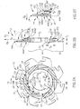
- Figs. 1A to 1C show a tool 10 for metal cutting operations, which is a rotary tool, comprising a plurality of cutting bodies 12, and a standard rotating/fastening tool 11 ( Fig. 1A ), which in this example can be an Allen key, for fine-tuning the cutting bodies 12.
- a tool 10 for metal cutting operations which is a rotary tool, comprising a plurality of cutting bodies 12, and a standard rotating/fastening tool 11 ( Fig. 1A ), which in this example can be an Allen key, for fine-tuning the cutting bodies 12.
- each cutting body 12 there are five cutting bodies 12 disposed directly adjacent to each other (as shown in Fig. 1C , the tool 10 is free of gaps between adjacent cutting bodies 12). More precisely, each cutting body 12 can be secured in an abutting manner to each adjacent cutting body 12. Such arrangement can allow multiple closely spaced cuts to be made.
- a central aperture 18 can be formed in the center of the cutting body 12.
- a body central axis A C can pass through the middle or mid-point 20 of the cutting body 12, which in this example can coincide with a mid-point of the central aperture 18.
- the cutting body 12 is configured to be used in a rotating tool, the cutting body 12 is configured for rotation about the body central axis A C .
- each cutting body 12 can comprise a body portion 14, a cutting portion 16 extending radially-outward therefrom, and a biasing member 17 ( Fig 2C ) respectively associated with, and configured for orienting, each associated cutting portion 16.
- the cutting portions 16 can be circumferentially spaced, equally or otherwise, about the body portion 14.
- the cutting portions 16 can be disposed in a staggered arrangement with respect to the cutting portions 16 of adjacent cutting bodies 12 (best shown in Fig. 1A ).
- Each cutting portion 16 can be unconnected to or, stated differently, spaced apart from adjacent cutting portions 16. More precisely, each cutting body 12 can be formed with a recess 19 ( Fig. 2A ) formed between adjacent cutting portions 16.
- Each recess 19 can extend to the body portion 14 and can extend, in this example of a disc-shaped tool, in a radial direction D R .
- Each cutting portion 16 can be configured for bending motion independent of position of adjacent cutting portions 16.
- Each cutting portion 16 can have a planar shape (e.g., as shown in the side view in Fig. 1C ).
- each cutting portion 16 extends from the body portion 14 and terminates at an opposing top end 16A.
- Each cutting portion 16 can have axially facing first and second major side surfaces 16B, 16C, which can be parallel to each other and can extend from the body portion 14 to the top end 16A.
- Each cutting portion 16 can have a magnitude of thickness T C ( Fig. 2B ), between the first and second side major surfaces 16B, 16C.
- each cutting portion 16 can have first and second minor side surfaces 16D, 16E.
- the first and second minor side surfaces 16D, 16E can be located on opposing sides of an associated cutting portion 16.
- the first and second minor side surfaces 16D, 16E can each extend between the body portion 14, the top end 16A and the first and second major side surfaces 16B, 16C.
- each cutting portion 16 can further have an insert 22 secured thereto in a removable manner.
- Each insert 22 has a cutting edge 24 disposed peripherally along the cutting body 12. It will be appreciated that the subject matter of the present application is not limited to any particular type of cutting portion 16, insert 22 or cutting edge 24.
- each cutting portion 16 is formed with a pocket 26 ( Fig. 2A ), to which the insert 22 is mounted.
- the body portion 14 is disc-shaped.
- the body portion 14 comprises an inner sub-portion 39 and an outer sub-portion 40 extending between the inner sub-portion 39 and each of the cutting portions 16.
- the inner sub-portion 39 can have a cylindrical shape.
- the inner sub-portion 39 can be defined between an inner peripheral end 28, an outer peripheral end 29, and first and second side surfaces 30, 32 extending therebetween.
- the inner sub-portion 39 can have a magnitude of radial depth D H .
- Such radial depth D H can be defined between the inner peripheral end 28 and the outer peripheral end 29.
- the inner peripheral end 28 can be formed with recesses 34 ( Fig. 2A ) configured for connection with a rotating shaft (not shown).
- the inner sub-portion 39 can have a solid or uniform construction, stated differently, the inner sub-portion 39 can be devoid of recesses or hollow areas.
- the first and second side surfaces 30, 32 can extend perpendicular to the body central axis A C (in this example in a radial plane including the radial direction D R ).
- the outer peripheral end 29 can be disposed at an intersection with the outer sub-portion 40.
- the outer sub-portion 40 comprises adjacent first and second sections 40A, 40B.
- the first section 40A extends between the inner sub-portion 39 and the cutting portion 16.
- the first section 40A has opposing first and second faces 40A1, 40A2.
- the first face 40A1 can extend between the inner sub-portion's first side surface 30 and the first major side surface 16B of the associated cutting portion 16.
- the second face 40A2 can extend from the second major side surface 16C of the associated cutting portion 16 toward the inner sub-portion 39.
- the second section 40B can be located radially outward from the inner sub-portion 39 and axially outward from the first section 40A.
- the second section 40B can comprise a biasing sub-portion 36A and a biasing surface 35 which faces in a generally radially outward direction.
- the second section 40B can also comprise an anchoring sub-portion 36B ( Fig. 2A ).
- a more precise definition of the first section 40A can be that it extends from the inner sub-portion 39, which ends adjacent the biasing surface 35, until an associated cutting portion 16, which starts adjacent to an upper edge 37A of the biasing sub-portion 36A.
- the biasing sub-portion 36A extends from the second face 40A2 of the first section 40A.
- the biasing sub-portion 36A can extend between the upper edge 37A and a lower edge 37B thereof.
- the upper and/or lower edges 37A, 37B can extend perpendicular to the second face 40A2.
- the upper edge 37A can be located further than the lower edge 37B from the body central axis A C .
- the lower edge 37B can terminate at a location spaced apart from the biasing surface 35. Stated differently, there can be a gap 37C between the lower edge 37B and the biasing surface 35.
- the biasing sub-portion 36A can be formed with an internally threaded bore 36A1 ( Fig. 2B ).
- the biasing sub-portion 36A can be elongated (best shown in Fig. 2A , in which an exemplary airfoil-like shape is shown). Such elongation can extend from the recess 19 associated with the second minor side surface 16E of the associated cutting portion 16 in a direction towards another one of the recesses 19 which is associated with the first minor side surface 16D of the same cutting portion 16. The elongation can extend along a majority of the distance between the recesses 19 of an associated cutting portion 16.
- the lower edge 37B can be flat.
- the flat lower edge 37B can extend in a direction tangential (D T ) to the body central axis A C .
- the upper edge 37A can be curved.
- the curved upper edge 37A can extend parallel with a portion of the biasing surface 35.
- a portion of the biasing surface 35 aligned with the threaded bore 36A1 can coincide with or, stated differently, co-constitute a portion of the outer peripheral end 29.
- a bore central axis A B ( Fig. 2B ) can extend through the center of threaded bore 36A1.
- the threaded bore 36A1 extends radially.
- the bore central axis A B can intersect or can extend proximate to the center 20 of the cutting body 12.
- the biasing surface 35 In an unbiased state, i.e., when the biasing member 17 is not applying forces to the biasing surface 35, the biasing surface 35 can form an angle ⁇ (shown in Fig. 2B , i.e., such angle can be seen in a side view) with the bore central axis A B of the threaded bore 36A1.
- the angle ⁇ can be between 88.5° to 92.5°, depending on a desired application.
- the angle ⁇ is 91.5° (the slant of the biasing surface 35 in Figs. 2B and 2C has been exaggerated for ease of visibility).
- An obtuse angle for example 91.5°, is believed to be advantageous over an acute angle, for example 88.5°, due to reduced sensitivity of the cutting portion 16 upon adjustment of the biasing member 17.
- the angle fulfill the condition 88.5° ⁇ ⁇ ⁇ 92.5°.
- the angle ⁇ is other than 90° ( ⁇ ⁇ 90°), which may affect force needed to initially move the biasing member 17.
- the bending motion can allow a range of movement of the associated cutting portion 16 of between 88.5° to 92.5°. Such range can be sufficient for fine-tuning while requiring a small number of turns of the fastening tool 11.
- the second section 40B can be formed with a biasing groove 42.
- the gap 37C can constitute a part of the biasing groove 42.
- the biasing groove 42 can have a first end 42A, which can open out to the recess 19 associated with the minor second side surface 16D of an associated cutting portion 16.
- the biasing groove 42 can have a closed second end 42B, terminating between the recess 19 associated with the minor first side surface 16E of an associated cutting portion 16 and the inner sub-portion 39 of the body portion 14.
- the biasing groove 42 can extend in the tangential direction D T .
- the biasing groove 42 can be defined between the lower edge 37B ( Fig. 2B ) of the biasing sub-portion 36A, the biasing surface 35 ( Fig. 2C ), and the second face 40A2 ( Fig. 2B ) of the first section 40A.
- the biasing groove 42 can be configured to provide localized flexibility to the cutting body 12. More specifically, the biasing groove 42 provides flexibility to the outer sub-portion 40 relative to the inner sub-portion 39, at an area disposed between the inner sub-portion 39 and an associated cutting portion 16. The elongation of the biasing groove 42 can correspond to an elongation of an associated cutting portion 16, to allow uniform bending movement to the entire associated cutting portion 16.
- the recesses 19 can also allow localized flexibility.
- the recesses 19 can serve to isolate the cutting portions 16 from each other. Consequently, the recesses 19 can allow uniform bending movement to the entire associated cutting portion 16.
- the recesses 19 can be formed between the cutting portions 16 and can also be formed in the outer sub-portion 40.
- the anchoring sub-portion 36B ( Fig. 2A ) can extend from the outer peripheral end 29 to the biasing sub-portion 36A thereby forming a linkage or neck therebetween.
- the anchoring sub-portion 36B can be defined between adjacent biasing grooves 42 and an associated recess 19 adjacent thereto.
- the anchoring sub-portion 36B can regulate bending movement of an associated cutting portion 16. Stated differently, the anchoring sub-portion 36B can limit bending movement of an associated cutting portion 16. Such regulation or limitation on the bending can counterbalance the elements which are designed to increase flexibility.
- each biasing groove 42 could feasibly extend from the first end 42A and open out to an adjacent biasing groove 42, i.e., being formed free of a second end 42B.
- an anchoring sub-portion 36B can possibly be advantageous for restricting overextension (i.e., excessive bending) of an associated cutting portion 16.
- the biasing member 17, in this non-limiting example, can be a screw with external threading 17C. It will be understood that the biasing member could be other than a screw, for example, a non-threaded lever or clamp member.
- the biasing member 17 can have a flat end 17A for engagement with the biasing surface 35.
- the biasing member 17 can have a length shorter than a length between the upper edge 37A and the biasing surface 35, so that it does not protrude from the biasing sub-portion 36A, in a direction towards an associated cutting portion 16, when mounted to the threaded bore 36A1. It is believed to be possibly advantageous for the biasing member 17 to be configured with a rotation inhibitor arrangement 17B.
- Such rotation inhibitor arrangement 17B can be, for example, a nylon patch secured to the external threading 17C of the screw, at least where the part which is to engage the threaded bore 36A1 during a cutting operation.
- Such patch can be configured to inhibit undesired rotation of the biasing member 17 in the threaded bore 36A1 during cutting operation of the associated cutting body 16.
- a suitable example patch is sold by the Bossard Group under the trade name Tuflok®.
- the patch could alternatively, or additionally, be applied to the threaded bore 36A1.
- such rotation inhibitor arrangement 17B could be the biasing member 17 having threading with a small pitch, i.e., pitch smaller than that defined by the International Organization for Standardization (ISO), for example smaller than that defined by the standard DIN 913 ISO 4026.
- ISO International Organization for Standardization
- the biasing member 17 can be inserted in the threaded bore 36A1.
- the biasing member 17 can be rotated via the tool 11 ( Fig. 1A ) in the threaded bore 36A1 until it touches the biasing surface 35 but does not apply force thereto, i.e., the cutting body 12 being in an unbiased state.
- every biasing member 17 can initially be rotated further into the threaded bore 36A1 so that it applies force to the biasing surface 35.
- the first section 40A is more flexible than the inner sub-portion 39, which in this non-limiting example is a result of the magnitude of thickness T C (of the first section 40A) being smaller than the magnitude of radial depth D H (of the inner sub-portion 39), the first section 40A bends in the direction D B ( Fig. 2C ; the bending not being shown).
- Each cutting portion 16 can then be calibrated to a desired position by rotating the biasing member 17 in an opposite direction until a desired bending angle between the unbiased state and the maximum bending angle is reached, which in this non-limiting example is 91.5° ( Fig. 2B ).
- the initial rotation can be to a predetermined maximum bending angle of 90° and the desired position can be achieved by rotating the biasing member 17 in an opposite direction until a desired bending angle between the unbiased state of 88.5° and the maximum bending angle is reached.
- Elasticity of the material of the first section 40A can cause the first section 40A to revert to the desired bending angle from the initial maximum bending angle.
- each cutting body 12 can be made of an elastic material, for example steel.
- at least the body portion 14, and more specifically, at least the first section 40A thereof is preferably made of an elastic material.
- a possible advantage of the radial orientation of the threaded bore 36A1 can be ease of access to rotate a biasing member 17 disposed therein, as a radial direction is more easily viewed and/or accessible than other directions.
- the subject matter of the present application can allow a plurality of cutting bodies to be mounted or packed directly adjacent to each another and to be adjusted while in this position.
- the threaded bore 36A1 could be slanted with respect to the second face 40A2 or cutting portion 16.
- the axis A B could be slanted with respect to the second face 40A2 or cutting portion 16, and the biasing surface 35 could be, for example, perpendicular to the second face 40A2 or cutting portion 16.
- the tool 10 is a so-called slotting-cutter, configured for simultaneously cutting a plurality of slots or grooves, and can also be configured to carry out simultaneous multiple parting of a workpiece, as desired.
- slotting-cutter configured for simultaneously cutting a plurality of slots or grooves
- other types of rotary tools in particular of the type having multiple blades, could also constitute a tool, or cutting body, in accordance with the subject matter of the present application.
- the biasing member 17, in the non-limiting example shown is distinct from any clamping mechanism of the cutting portion 16, i.e., relating to the cutting insert 22 or the cutting edge 24. More precisely, the cutting portion 16 is devoid of biasing elements or portions. Accordingly, there is no thickness limitation of the cutting portion 16 caused by a biasing elements or portions such as a threaded bore, biasing member or portion, on the cutting portion 16.
- a possible advantage of this arrangement can be that a cutting portion is not limited to a width required for accommodating biasing elements and an extremely thin cut or plurality of cuts, especially in a case where there are multiple adjacent cutting bodies, can be achieved. It will be understood that the orientation of the threaded bore 36A1 (i.e., being radially oriented), can allow an operator access even in the compact arrangement shown.
- one or more of (a) the biasing member 17, (b) the biasing surface 35, and (c) the threaded bore 36A1 are disposed between an associated cutting portion 16 and the center 20 of the cutting body 12. Stated differently, the biasing member 17 and/or the biasing surface 35 and/or the threaded bore 36A1 are located closer to the center 20 of the cutting body 12 than the cutting portion 16.
- a cutting body is provided which is configured to be flexible at an intersection of a cutting portion and body portion thereof for allowing adjustment of the cutting portion position.
- the cutting portion can have an anchoring arrangement to regulate the flexibility, stabilize or restrict excessive movement of the cutting portion.
Claims (13)
- Corps de coupe (12) pour une machine-outil d'usinage de métal pour un travail par enlèvement de matière, comprenant :une partie de corps (14),une partie de coupe (16) s'étendant à partir de la partie de corps (14), etun élément de sollicitation (17) ;la partie de corps (14) comprenant :une partie auxiliaire interne (39), etune partie auxiliaire externe (40) disposée entre la partie auxiliaire interne (39) et la partie de coupe (16) ;la partie auxiliaire externe (40) comprenant des première et seconde sections (40A, 40B) adjacentes ;la première section (40A) s'étendant entre la partie auxiliaire interne (39) et la partie de coupe (16) et comprenant une face (40A2) adjacente à la seconde section (40B) ;la seconde section (40B) comprenant :une surface de sollicitation (35) s'étendant transversalement par rapport à la face (40A2) de la première section, etune partie auxiliaire de sollicitation (36A) maintenant l'élément de sollicitation (17) et raccordée à la face (40A2) de la première section ;la première section (40A) étant configurée pour se plier élastiquement suite à l'actionnement de l'élément de sollicitation (17) dû à l'application de force sur la surface de sollicitation (35) par l'élément de sollicitation (17), faisant changer ainsi la position de la partie de coupe (16) pour son réglage fin, caractérisé en ce que :
la partie de corps (14) est en forme de disque et la partie auxiliaire de sollicitation (36A) est formée avec un alésage fileté (36A1) s'étendant dans une direction radiale (DR), étant dirigé vers la surface de sollicitation (35) et ayant un axe central d'alésage (AB) s'étendant à travers son centre. - Corps de coupe (12) selon la revendication précédente, comprenant en outre au moins une partie de coupe supplémentaire (16), dans lequel un évidement (19) est formé entre des parties de coupe (16) adjacentes.
- Corps de coupe (12) selon la revendication précédente, dans lequel une première direction (DR) est définie de la partie de corps (14) à la partie de coupe (16) et chaque évidement (19) entre des parties de coupe (16) adjacentes s'étend parallèlement à la première direction (DR).
- Corps de coupe (12) selon l'une quelconque des revendications précédentes, dans lequel la seconde section (40B) est formée avec un espace (37C) positionné entre la partie auxiliaire de sollicitation (36A) et la surface de sollicitation (35).
- Corps de coupe (12) selon la revendication précédente, dans lequel l'espace (37C) fait partie d'une rainure de sollicitation allongée (42).
- Corps de coupe (12) selon la revendication précédente, dans lequel la rainure de sollicitation (42) s'étend dans une direction qui est perpendiculaire à une première direction (DR) définie de la partie de corps (14) à la partie de coupe (16).
- Corps de coupe (12) selon l'une quelconque des revendications précédentes, dans lequel la seconde section (40B) comprend en outre une partie auxiliaire d'ancrage (36B) raccordée entre la partie auxiliaire interne (39) et la partie auxiliaire de sollicitation (36A), pour limiter le mouvement de pliage de la partie de coupe (16).
- Corps de coupe (12) selon l'une quelconque des revendications précédentes, dans lequel la partie auxiliaire de sollicitation (36A) est plus proche de la partie de coupe (16) que la surface de sollicitation (35).
- Corps de coupe (12) selon l'une quelconque des revendications précédentes, dans lequel la direction de la rainure de sollicitation (42) est dans une direction tangentielle.
- Corps de coupe (12) selon l'une quelconque des revendications précédentes, dans lequel l'axe centrale d'alésage (AB) forme un angle α avec la surface de sollicitation (35) entre 88,5° et 92,5°, formant de préférence un angle obtus α avec la surface de sollicitation (35).
- Corps de coupe (12) selon l'une quelconque des revendications précédentes, dans lequel, dans un état non sollicité, l'angle α est différent de 90° (α ≠ 90°).
- Corps de coupe (12) selon l'une quelconque des revendications précédentes, dans lequel la partie de coupe (16) est uniquement raccordée à la partie de corps (14) au niveau de l'un de ses côtés, pour permettre le pliage de la partie de coupe (16) sans affecter les autres parties du corps de coupe (12) ; la partie de corps (14) comprenant en outre une rainure de sollicitation allongée (42) qui s'étend au-dessous de la partie de coupe (16) pour permettre en outre le pliage localisé et uniforme de la partie de coupe (16), et la partie auxiliaire de sollicitation (36A) et la surface de sollicitation (35) sont disposées sur les côtés opposés de la rainure de sollicitation (42).
- Machine-outil (10) pour le travail par enlèvement de matière comprenant une pluralité de corps de coupe (12) selon l'une quelconque des revendications précédentes, dans laquelle chacun des corps de coupe (12) vient en butée contre au moins un corps de coupe (12) adjacent.
Applications Claiming Priority (2)
| Application Number | Priority Date | Filing Date | Title |
|---|---|---|---|
| US201161509261P | 2011-07-19 | 2011-07-19 | |
| PCT/IL2012/000276 WO2013011499A1 (fr) | 2011-07-19 | 2012-07-08 | Corps de coupe configuré pour un réglage fin |
Publications (2)
| Publication Number | Publication Date |
|---|---|
| EP2734329A1 EP2734329A1 (fr) | 2014-05-28 |
| EP2734329B1 true EP2734329B1 (fr) | 2020-12-09 |
Family
ID=46796693
Family Applications (1)
| Application Number | Title | Priority Date | Filing Date |
|---|---|---|---|
| EP12754098.7A Active EP2734329B1 (fr) | 2011-07-19 | 2012-07-08 | Corps de coupe configuré pour un réglage fin |
Country Status (10)
| Country | Link |
|---|---|
| US (1) | US9216461B2 (fr) |
| EP (1) | EP2734329B1 (fr) |
| JP (1) | JP5966005B2 (fr) |
| KR (1) | KR101675205B1 (fr) |
| CN (1) | CN103687686B (fr) |
| BR (1) | BR112013033894A2 (fr) |
| CA (1) | CA2842499C (fr) |
| IL (1) | IL230175A (fr) |
| RU (1) | RU2594298C2 (fr) |
| WO (1) | WO2013011499A1 (fr) |
Families Citing this family (19)
| Publication number | Priority date | Publication date | Assignee | Title |
|---|---|---|---|---|
| DE202013102690U1 (de) * | 2013-06-21 | 2013-07-01 | Albert Knebel Gmbh & Co. Kg Holding | Sägeblatt mit kleinem Sägezahn |
| CN105517744B (zh) * | 2013-09-04 | 2018-06-12 | 格里森工场 | 使用棒形刀片的周缘切削刀具 |
| US9475138B2 (en) * | 2014-01-22 | 2016-10-25 | Kennametal Inc. | Cutting tool having insert pocket with cantilevered member |
| US9427811B2 (en) * | 2014-05-07 | 2016-08-30 | Iscar, Ltd. | Rotary slitter with cutting insert edge positioning arrangement |
| CN107206514B (zh) * | 2015-07-10 | 2020-02-28 | 株式会社泰珂洛 | 作业工具、调整机构、工具体及切削工具 |
| EP3334549B1 (fr) * | 2015-08-10 | 2019-11-27 | Illinois Tool Works Inc. | Coupe-tube mobile avec outil de coupe pour tube à grand diamètre |
| US10220456B2 (en) | 2015-08-10 | 2019-03-05 | Illinois Tool Works Inc. | Large diameter travelling pipe cutter |
| US10183347B2 (en) | 2015-09-08 | 2019-01-22 | Iscar, Ltd. | Rotary cutting tool having axial position adjustment arrangement |
| DE102015115310A1 (de) * | 2015-09-10 | 2017-03-16 | Hartmetall-Werkzeugfabrik Paul Horn Gmbh | Wirbelwerkzeug |
| CN105965593A (zh) * | 2016-06-24 | 2016-09-28 | 无锡欧诺锁业有限公司 | 一种可调节的切割机 |
| DE102016216464A1 (de) * | 2016-08-31 | 2018-03-01 | Gühring KG | Aufrauwerkzeug und verfahren zum aufrauen einer zylindrischen oberfläche |
| BR112019004126B1 (pt) * | 2016-09-06 | 2022-07-12 | Iscar Ltd | Adaptador de elemento de inserção para particionar que tem um eixo geométrico de índice de adaptador |
| DE102017202394A1 (de) * | 2017-02-15 | 2018-08-16 | Hoffmann GmbH Qualitätswerkzeuge | Vorrichtung zur Bearbeitung von Zylinderwänden von Verbrennungsmotoren |
| US11420272B2 (en) * | 2019-01-08 | 2022-08-23 | Iscar, Ltd. | Milling head having integrally formed cutting edges and rotary milling tool |
| US11590590B2 (en) | 2020-03-12 | 2023-02-28 | Iscar, Ltd. | Reinforced metal slitter body having insert pockets |
| US11571759B2 (en) * | 2020-12-09 | 2023-02-07 | Kennametal Inc. | Cutting tool with directed fluid flow to facilitate chip evacuation |
| DE102021112412A1 (de) | 2021-05-12 | 2022-11-17 | Erwin Quarder Systemtechnik Gmbh | Kühlkörper aus Metall sowie Verfahren zur Herstellung desselben |
| US11883894B2 (en) | 2021-07-13 | 2024-01-30 | Kennametal Inc. | Composite cutting tool |
| US11911835B2 (en) | 2022-03-23 | 2024-02-27 | Kennametal Inc. | Lightweight rotary cutting tool |
Family Cites Families (38)
| Publication number | Priority date | Publication date | Assignee | Title |
|---|---|---|---|---|
| US301986A (en) * | 1884-07-15 | Jambs hilton | ||
| US197325A (en) * | 1877-11-20 | Improvement in planing-saws | ||
| US1495067A (en) * | 1922-12-22 | 1924-05-20 | O K Tool Co | Hob having side-tooth inserts |
| US2544920A (en) * | 1947-09-03 | 1951-03-13 | Pittsburgh Saw & Tool Company | Insert segment saw |
| US3023486A (en) * | 1959-10-12 | 1962-03-06 | Wesson Corp | Giant mill |
| US4218159A (en) * | 1977-01-07 | 1980-08-19 | Sack Gmbh | Multiple-part hobbing cutter |
| DE3039076A1 (de) * | 1980-10-16 | 1982-05-13 | Wilhelm Fette Gmbh, 2053 Schwarzenbek | Waelzfraeser mit schneidplatten |
| US4547100A (en) | 1983-09-28 | 1985-10-15 | The Valeron Corporation | Adjustable milling cutter |
| SU1194600A1 (ru) * | 1983-10-21 | 1985-11-30 | Nagajtsev Vladimir F | Фреза дискова трехсторонн |
| SE454490B (sv) * | 1984-07-05 | 1988-05-09 | Seco Tools Ab | Fres med instellbar kassett |
| US4563929A (en) * | 1984-08-30 | 1986-01-14 | Weyerhaeuser Company | Field repairable circular saw |
| GB2164883B (en) * | 1984-09-29 | 1988-04-13 | Honda Motor Co Ltd | Milling cutter assembly |
| DE3607528C1 (en) | 1986-03-07 | 1987-01-29 | Audi Ag | Milling cutter head |
| JPH0192313U (fr) * | 1987-12-08 | 1989-06-16 | ||
| SU1502212A1 (ru) | 1987-12-21 | 1989-08-23 | Всесоюзный Научно-Исследовательский Инструментальный Институт | Сборный режущий инструмент |
| SU1537418A1 (ru) * | 1988-01-04 | 1990-01-23 | А. С. Обломов | Приспособление дл прошивани |
| DE3929007A1 (de) * | 1989-09-01 | 1991-03-07 | Fette Wilhelm Gmbh | Scheibenfraeser mit wendeschneidplatten und verstellbarer schnittbreite |
| US5201353A (en) * | 1991-07-25 | 1993-04-13 | Weill Theodore C | Reconfigurable debarker head |
| DE29508112U1 (de) * | 1995-05-17 | 1995-08-10 | Leitz Geb Gmbh & Co | Profilmesserkopf |
| US6056484A (en) | 1998-08-07 | 2000-05-02 | Kennametal Inc. | Device and method for adjusting the position of cutting inserts mounted in a cutting tool |
| US6431799B1 (en) | 1999-12-17 | 2002-08-13 | Kennametal Pc Inc. | Slotting cutter |
| DE10011113A1 (de) | 2000-03-09 | 2001-09-13 | Komet Stahlhalter Werkzeuge | Maschinenwerkzeug mit verstellbarer Schneide |
| DE10137747A1 (de) * | 2001-08-01 | 2003-02-13 | Hilti Ag | Bohrkrone |
| US7216682B1 (en) * | 2001-12-31 | 2007-05-15 | Bennington John T | Split wheel stump cutter with replaceable tooth blocks and cutting teeth |
| US6702526B2 (en) | 2002-04-29 | 2004-03-09 | Kennametal Inc. | Cutting tool |
| JP4420827B2 (ja) | 2002-08-13 | 2010-02-24 | ケンナメタル ヴィディア プロドゥクツィオーンス ゲゼルシャフト ミット ベシュレンクテル ハフツング ウント コンパニー コマンディートゲゼルシャフト | ディスク状またはストリップ状の工具 |
| BR0314331A (pt) * | 2002-09-03 | 2005-07-19 | Kennametal Inc | Porta-ferramenta e ferramenta para máquina |
| DE102007013153B4 (de) * | 2007-03-20 | 2019-01-24 | Kennametal Inc. | Werkzeug |
| JP2009095894A (ja) | 2007-10-12 | 2009-05-07 | Sumitomo Electric Hardmetal Corp | 刃先調整機構及びそれを用いた切削工具 |
| SE531858C2 (sv) * | 2007-12-21 | 2009-08-25 | Sandvik Intellectual Property | Fräsverktyg för spånavskiljande bearbetning, samt skärkropp och grundkropp härför |
| IL190734A (en) * | 2008-04-08 | 2013-08-29 | Iscar Ltd | Tuning mechanism |
| DE102009016257B4 (de) * | 2008-12-16 | 2017-09-07 | Kennametal Inc. | Wälzfräser |
| DE102009030856A1 (de) * | 2009-06-26 | 2010-12-30 | Kennametal Inc. | Verfahren und Vorrichtung zur endmaßgenauen Bearbeitung von Kurbel- oder Nockenwellen |
| US8388270B2 (en) * | 2010-01-28 | 2013-03-05 | Kennametal Inc. | Slotting cutter with cantilevered member |
| IL208494B (en) * | 2010-10-05 | 2018-03-29 | Iscar Ltd | Rotary cutting tool and cutting tool for it |
| SE535941C2 (sv) * | 2011-06-20 | 2013-02-26 | Sandvik Intellectual Property | Fräsverktyg för hobbning samt segment härför |
| US8985916B2 (en) * | 2011-09-19 | 2015-03-24 | Sandvik Intellectual Property Ab | Flexible cartridge with precision adjustment |
| US8851807B2 (en) * | 2012-12-26 | 2014-10-07 | Iscar, Ltd. | Cutting tool having axial position adjustment arrangement |
-
2012
- 2012-07-06 US US13/542,915 patent/US9216461B2/en active Active
- 2012-07-08 BR BR112013033894A patent/BR112013033894A2/pt not_active Application Discontinuation
- 2012-07-08 JP JP2014520788A patent/JP5966005B2/ja not_active Expired - Fee Related
- 2012-07-08 EP EP12754098.7A patent/EP2734329B1/fr active Active
- 2012-07-08 CN CN201280035675.9A patent/CN103687686B/zh not_active Expired - Fee Related
- 2012-07-08 RU RU2014106030/02A patent/RU2594298C2/ru active
- 2012-07-08 KR KR1020147000712A patent/KR101675205B1/ko active IP Right Grant
- 2012-07-08 CA CA2842499A patent/CA2842499C/fr not_active Expired - Fee Related
- 2012-07-08 WO PCT/IL2012/000276 patent/WO2013011499A1/fr active Application Filing
-
2013
- 2013-12-26 IL IL230175A patent/IL230175A/en active IP Right Grant
Non-Patent Citations (1)
| Title |
|---|
| None * |
Also Published As
| Publication number | Publication date |
|---|---|
| IL230175A (en) | 2016-08-31 |
| JP2014520683A (ja) | 2014-08-25 |
| JP5966005B2 (ja) | 2016-08-10 |
| WO2013011499A1 (fr) | 2013-01-24 |
| CN103687686A (zh) | 2014-03-26 |
| US9216461B2 (en) | 2015-12-22 |
| RU2014106030A (ru) | 2015-08-27 |
| CA2842499C (fr) | 2017-10-24 |
| KR20140045976A (ko) | 2014-04-17 |
| RU2594298C2 (ru) | 2016-08-10 |
| KR101675205B1 (ko) | 2016-11-10 |
| BR112013033894A2 (pt) | 2017-02-14 |
| CN103687686B (zh) | 2016-09-28 |
| US20130022414A1 (en) | 2013-01-24 |
| EP2734329A1 (fr) | 2014-05-28 |
| CA2842499A1 (fr) | 2013-01-24 |
Similar Documents
| Publication | Publication Date | Title |
|---|---|---|
| EP2734329B1 (fr) | Corps de coupe configuré pour un réglage fin | |
| US8701537B2 (en) | Cutting tool with detachably connected inserts | |
| EP2938450B1 (fr) | Outil de coupe doté d'un agencement de réglage de position axiale | |
| EP3347153B1 (fr) | Outil de coupe rotatif ayant un agencement de réglage de position axiale | |
| EP2872278B1 (fr) | Outil à rainurer conçu pour un réglage précis | |
| EP3144086B1 (fr) | Corps d'outil et outil de tournage pour des opérations de rainurage | |
| CN110325306B (zh) | 孔加工工具和用于孔加工工具的引导垫调节机构 | |
| EP2999563B1 (fr) | Plaquette de coupe à arête de coupe décalée vers l'arrière et outil de coupe | |
| EP3095541B1 (fr) | Outil de coupe avec un élément en forme de plaque et un bloc d'outil | |
| EP2420340B1 (fr) | Insert pour filetage par fraisage et fraise à fileter | |
| KR20160050035A (ko) | 스틱 블레이드를 이용한 외주 절삭 공구 | |
| WO2010027055A1 (fr) | Découpeur latéral | |
| US9770768B2 (en) | Rotary cutting tool with anti-rotation feature | |
| EP2581157B1 (fr) | Outil de découpe pour opérations de rainurage ou de partition | |
| CA2699351C (fr) | Broche d'appui axiale | |
| EP3582919B1 (fr) | Corps d'outil pourvu d'une poche interne de réception d'insert à élément de serrage souple, outil de coupe et insert de coupe pour chanfreinage correspondant | |
| JP2006150491A (ja) | フライスカッター |
Legal Events
| Date | Code | Title | Description |
|---|---|---|---|
| PUAI | Public reference made under article 153(3) epc to a published international application that has entered the european phase |
Free format text: ORIGINAL CODE: 0009012 |
|
| 17P | Request for examination filed |
Effective date: 20140206 |
|
| AK | Designated contracting states |
Kind code of ref document: A1 Designated state(s): AL AT BE BG CH CY CZ DE DK EE ES FI FR GB GR HR HU IE IS IT LI LT LU LV MC MK MT NL NO PL PT RO RS SE SI SK SM TR |
|
| DAX | Request for extension of the european patent (deleted) | ||
| STAA | Information on the status of an ep patent application or granted ep patent |
Free format text: STATUS: EXAMINATION IS IN PROGRESS |
|
| 17Q | First examination report despatched |
Effective date: 20180608 |
|
| GRAP | Despatch of communication of intention to grant a patent |
Free format text: ORIGINAL CODE: EPIDOSNIGR1 |
|
| STAA | Information on the status of an ep patent application or granted ep patent |
Free format text: STATUS: GRANT OF PATENT IS INTENDED |
|
| INTG | Intention to grant announced |
Effective date: 20200618 |
|
| GRAS | Grant fee paid |
Free format text: ORIGINAL CODE: EPIDOSNIGR3 |
|
| GRAA | (expected) grant |
Free format text: ORIGINAL CODE: 0009210 |
|
| STAA | Information on the status of an ep patent application or granted ep patent |
Free format text: STATUS: THE PATENT HAS BEEN GRANTED |
|
| AK | Designated contracting states |
Kind code of ref document: B1 Designated state(s): AL AT BE BG CH CY CZ DE DK EE ES FI FR GB GR HR HU IE IS IT LI LT LU LV MC MK MT NL NO PL PT RO RS SE SI SK SM TR |
|
| REG | Reference to a national code |
Ref country code: GB Ref legal event code: FG4D |
|
| REG | Reference to a national code |
Ref country code: AT Ref legal event code: REF Ref document number: 1342902 Country of ref document: AT Kind code of ref document: T Effective date: 20201215 Ref country code: CH Ref legal event code: EP |
|
| REG | Reference to a national code |
Ref country code: DE Ref legal event code: R096 Ref document number: 602012073636 Country of ref document: DE |
|
| REG | Reference to a national code |
Ref country code: IE Ref legal event code: FG4D |
|
| PG25 | Lapsed in a contracting state [announced via postgrant information from national office to epo] |
Ref country code: GR Free format text: LAPSE BECAUSE OF FAILURE TO SUBMIT A TRANSLATION OF THE DESCRIPTION OR TO PAY THE FEE WITHIN THE PRESCRIBED TIME-LIMIT Effective date: 20210310 Ref country code: NO Free format text: LAPSE BECAUSE OF FAILURE TO SUBMIT A TRANSLATION OF THE DESCRIPTION OR TO PAY THE FEE WITHIN THE PRESCRIBED TIME-LIMIT Effective date: 20210309 Ref country code: RS Free format text: LAPSE BECAUSE OF FAILURE TO SUBMIT A TRANSLATION OF THE DESCRIPTION OR TO PAY THE FEE WITHIN THE PRESCRIBED TIME-LIMIT Effective date: 20201209 Ref country code: FI Free format text: LAPSE BECAUSE OF FAILURE TO SUBMIT A TRANSLATION OF THE DESCRIPTION OR TO PAY THE FEE WITHIN THE PRESCRIBED TIME-LIMIT Effective date: 20201209 |
|
| REG | Reference to a national code |
Ref country code: AT Ref legal event code: MK05 Ref document number: 1342902 Country of ref document: AT Kind code of ref document: T Effective date: 20201209 |
|
| PG25 | Lapsed in a contracting state [announced via postgrant information from national office to epo] |
Ref country code: LV Free format text: LAPSE BECAUSE OF FAILURE TO SUBMIT A TRANSLATION OF THE DESCRIPTION OR TO PAY THE FEE WITHIN THE PRESCRIBED TIME-LIMIT Effective date: 20201209 Ref country code: SE Free format text: LAPSE BECAUSE OF FAILURE TO SUBMIT A TRANSLATION OF THE DESCRIPTION OR TO PAY THE FEE WITHIN THE PRESCRIBED TIME-LIMIT Effective date: 20201209 Ref country code: BG Free format text: LAPSE BECAUSE OF FAILURE TO SUBMIT A TRANSLATION OF THE DESCRIPTION OR TO PAY THE FEE WITHIN THE PRESCRIBED TIME-LIMIT Effective date: 20210309 |
|
| REG | Reference to a national code |
Ref country code: NL Ref legal event code: MP Effective date: 20201209 |
|
| PG25 | Lapsed in a contracting state [announced via postgrant information from national office to epo] |
Ref country code: NL Free format text: LAPSE BECAUSE OF FAILURE TO SUBMIT A TRANSLATION OF THE DESCRIPTION OR TO PAY THE FEE WITHIN THE PRESCRIBED TIME-LIMIT Effective date: 20201209 Ref country code: HR Free format text: LAPSE BECAUSE OF FAILURE TO SUBMIT A TRANSLATION OF THE DESCRIPTION OR TO PAY THE FEE WITHIN THE PRESCRIBED TIME-LIMIT Effective date: 20201209 |
|
| REG | Reference to a national code |
Ref country code: LT Ref legal event code: MG9D |
|
| PG25 | Lapsed in a contracting state [announced via postgrant information from national office to epo] |
Ref country code: RO Free format text: LAPSE BECAUSE OF FAILURE TO SUBMIT A TRANSLATION OF THE DESCRIPTION OR TO PAY THE FEE WITHIN THE PRESCRIBED TIME-LIMIT Effective date: 20201209 Ref country code: PT Free format text: LAPSE BECAUSE OF FAILURE TO SUBMIT A TRANSLATION OF THE DESCRIPTION OR TO PAY THE FEE WITHIN THE PRESCRIBED TIME-LIMIT Effective date: 20210409 Ref country code: SK Free format text: LAPSE BECAUSE OF FAILURE TO SUBMIT A TRANSLATION OF THE DESCRIPTION OR TO PAY THE FEE WITHIN THE PRESCRIBED TIME-LIMIT Effective date: 20201209 Ref country code: LT Free format text: LAPSE BECAUSE OF FAILURE TO SUBMIT A TRANSLATION OF THE DESCRIPTION OR TO PAY THE FEE WITHIN THE PRESCRIBED TIME-LIMIT Effective date: 20201209 Ref country code: SM Free format text: LAPSE BECAUSE OF FAILURE TO SUBMIT A TRANSLATION OF THE DESCRIPTION OR TO PAY THE FEE WITHIN THE PRESCRIBED TIME-LIMIT Effective date: 20201209 Ref country code: CZ Free format text: LAPSE BECAUSE OF FAILURE TO SUBMIT A TRANSLATION OF THE DESCRIPTION OR TO PAY THE FEE WITHIN THE PRESCRIBED TIME-LIMIT Effective date: 20201209 Ref country code: EE Free format text: LAPSE BECAUSE OF FAILURE TO SUBMIT A TRANSLATION OF THE DESCRIPTION OR TO PAY THE FEE WITHIN THE PRESCRIBED TIME-LIMIT Effective date: 20201209 |
|
| PG25 | Lapsed in a contracting state [announced via postgrant information from national office to epo] |
Ref country code: AT Free format text: LAPSE BECAUSE OF FAILURE TO SUBMIT A TRANSLATION OF THE DESCRIPTION OR TO PAY THE FEE WITHIN THE PRESCRIBED TIME-LIMIT Effective date: 20201209 Ref country code: PL Free format text: LAPSE BECAUSE OF FAILURE TO SUBMIT A TRANSLATION OF THE DESCRIPTION OR TO PAY THE FEE WITHIN THE PRESCRIBED TIME-LIMIT Effective date: 20201209 |
|
| REG | Reference to a national code |
Ref country code: DE Ref legal event code: R097 Ref document number: 602012073636 Country of ref document: DE |
|
| PG25 | Lapsed in a contracting state [announced via postgrant information from national office to epo] |
Ref country code: IS Free format text: LAPSE BECAUSE OF FAILURE TO SUBMIT A TRANSLATION OF THE DESCRIPTION OR TO PAY THE FEE WITHIN THE PRESCRIBED TIME-LIMIT Effective date: 20210409 |
|
| PLBE | No opposition filed within time limit |
Free format text: ORIGINAL CODE: 0009261 |
|
| STAA | Information on the status of an ep patent application or granted ep patent |
Free format text: STATUS: NO OPPOSITION FILED WITHIN TIME LIMIT |
|
| PG25 | Lapsed in a contracting state [announced via postgrant information from national office to epo] |
Ref country code: IT Free format text: LAPSE BECAUSE OF FAILURE TO SUBMIT A TRANSLATION OF THE DESCRIPTION OR TO PAY THE FEE WITHIN THE PRESCRIBED TIME-LIMIT Effective date: 20201209 Ref country code: AL Free format text: LAPSE BECAUSE OF FAILURE TO SUBMIT A TRANSLATION OF THE DESCRIPTION OR TO PAY THE FEE WITHIN THE PRESCRIBED TIME-LIMIT Effective date: 20201209 |
|
| 26N | No opposition filed |
Effective date: 20210910 |
|
| PG25 | Lapsed in a contracting state [announced via postgrant information from national office to epo] |
Ref country code: ES Free format text: LAPSE BECAUSE OF FAILURE TO SUBMIT A TRANSLATION OF THE DESCRIPTION OR TO PAY THE FEE WITHIN THE PRESCRIBED TIME-LIMIT Effective date: 20201209 Ref country code: DK Free format text: LAPSE BECAUSE OF FAILURE TO SUBMIT A TRANSLATION OF THE DESCRIPTION OR TO PAY THE FEE WITHIN THE PRESCRIBED TIME-LIMIT Effective date: 20201209 Ref country code: SI Free format text: LAPSE BECAUSE OF FAILURE TO SUBMIT A TRANSLATION OF THE DESCRIPTION OR TO PAY THE FEE WITHIN THE PRESCRIBED TIME-LIMIT Effective date: 20201209 |
|
| REG | Reference to a national code |
Ref country code: CH Ref legal event code: PL |
|
| GBPC | Gb: european patent ceased through non-payment of renewal fee |
Effective date: 20210708 |
|
| PG25 | Lapsed in a contracting state [announced via postgrant information from national office to epo] |
Ref country code: MC Free format text: LAPSE BECAUSE OF FAILURE TO SUBMIT A TRANSLATION OF THE DESCRIPTION OR TO PAY THE FEE WITHIN THE PRESCRIBED TIME-LIMIT Effective date: 20201209 |
|
| REG | Reference to a national code |
Ref country code: BE Ref legal event code: MM Effective date: 20210731 |
|
| PG25 | Lapsed in a contracting state [announced via postgrant information from national office to epo] |
Ref country code: LI Free format text: LAPSE BECAUSE OF NON-PAYMENT OF DUE FEES Effective date: 20210731 Ref country code: GB Free format text: LAPSE BECAUSE OF NON-PAYMENT OF DUE FEES Effective date: 20210708 Ref country code: CH Free format text: LAPSE BECAUSE OF NON-PAYMENT OF DUE FEES Effective date: 20210731 |
|
| PG25 | Lapsed in a contracting state [announced via postgrant information from national office to epo] |
Ref country code: IS Free format text: LAPSE BECAUSE OF FAILURE TO SUBMIT A TRANSLATION OF THE DESCRIPTION OR TO PAY THE FEE WITHIN THE PRESCRIBED TIME-LIMIT Effective date: 20210409 Ref country code: LU Free format text: LAPSE BECAUSE OF NON-PAYMENT OF DUE FEES Effective date: 20210708 Ref country code: FR Free format text: LAPSE BECAUSE OF NON-PAYMENT OF DUE FEES Effective date: 20210731 |
|
| PG25 | Lapsed in a contracting state [announced via postgrant information from national office to epo] |
Ref country code: IE Free format text: LAPSE BECAUSE OF NON-PAYMENT OF DUE FEES Effective date: 20210708 Ref country code: BE Free format text: LAPSE BECAUSE OF NON-PAYMENT OF DUE FEES Effective date: 20210731 |
|
| PG25 | Lapsed in a contracting state [announced via postgrant information from national office to epo] |
Ref country code: HU Free format text: LAPSE BECAUSE OF FAILURE TO SUBMIT A TRANSLATION OF THE DESCRIPTION OR TO PAY THE FEE WITHIN THE PRESCRIBED TIME-LIMIT; INVALID AB INITIO Effective date: 20120708 Ref country code: CY Free format text: LAPSE BECAUSE OF FAILURE TO SUBMIT A TRANSLATION OF THE DESCRIPTION OR TO PAY THE FEE WITHIN THE PRESCRIBED TIME-LIMIT Effective date: 20201209 |
|
| P01 | Opt-out of the competence of the unified patent court (upc) registered |
Effective date: 20230426 |
|
| PGFP | Annual fee paid to national office [announced via postgrant information from national office to epo] |
Ref country code: DE Payment date: 20230605 Year of fee payment: 12 |
|
| PG25 | Lapsed in a contracting state [announced via postgrant information from national office to epo] |
Ref country code: MK Free format text: LAPSE BECAUSE OF FAILURE TO SUBMIT A TRANSLATION OF THE DESCRIPTION OR TO PAY THE FEE WITHIN THE PRESCRIBED TIME-LIMIT Effective date: 20201209 |