EP2734323B1 - Molded part - Google Patents
Molded part Download PDFInfo
- Publication number
- EP2734323B1 EP2734323B1 EP12755946.6A EP12755946A EP2734323B1 EP 2734323 B1 EP2734323 B1 EP 2734323B1 EP 12755946 A EP12755946 A EP 12755946A EP 2734323 B1 EP2734323 B1 EP 2734323B1
- Authority
- EP
- European Patent Office
- Prior art keywords
- geometry
- molded part
- elevations
- inclination
- row
- Prior art date
- Legal status (The legal status is an assumption and is not a legal conclusion. Google has not performed a legal analysis and makes no representation as to the accuracy of the status listed.)
- Active
Links
- 239000000843 powder Substances 0.000 claims description 9
- 238000003825 pressing Methods 0.000 description 18
- 238000004519 manufacturing process Methods 0.000 description 15
- 239000007789 gas Substances 0.000 description 12
- 239000000446 fuel Substances 0.000 description 11
- 238000000465 moulding Methods 0.000 description 7
- 238000004663 powder metallurgy Methods 0.000 description 5
- 230000007704 transition Effects 0.000 description 5
- 238000006243 chemical reaction Methods 0.000 description 4
- 239000000463 material Substances 0.000 description 4
- 238000000034 method Methods 0.000 description 4
- 230000008569 process Effects 0.000 description 4
- 238000000926 separation method Methods 0.000 description 4
- 229910045601 alloy Inorganic materials 0.000 description 3
- 239000000956 alloy Substances 0.000 description 3
- UFHFLCQGNIYNRP-UHFFFAOYSA-N Hydrogen Chemical compound [H][H] UFHFLCQGNIYNRP-UHFFFAOYSA-N 0.000 description 2
- 239000011651 chromium Substances 0.000 description 2
- 238000005868 electrolysis reaction Methods 0.000 description 2
- 239000001257 hydrogen Substances 0.000 description 2
- 229910052739 hydrogen Inorganic materials 0.000 description 2
- 238000005245 sintering Methods 0.000 description 2
- 239000007787 solid Substances 0.000 description 2
- VYZAMTAEIAYCRO-UHFFFAOYSA-N Chromium Chemical compound [Cr] VYZAMTAEIAYCRO-UHFFFAOYSA-N 0.000 description 1
- 229910000946 Y alloy Inorganic materials 0.000 description 1
- 238000005275 alloying Methods 0.000 description 1
- 230000015572 biosynthetic process Effects 0.000 description 1
- 230000008859 change Effects 0.000 description 1
- 229910052804 chromium Inorganic materials 0.000 description 1
- 238000007906 compression Methods 0.000 description 1
- 230000006835 compression Effects 0.000 description 1
- 230000002950 deficient Effects 0.000 description 1
- 238000005516 engineering process Methods 0.000 description 1
- 230000007774 longterm Effects 0.000 description 1
- 238000003754 machining Methods 0.000 description 1
- 230000003647 oxidation Effects 0.000 description 1
- 238000007254 oxidation reaction Methods 0.000 description 1
- 239000011224 oxide ceramic Substances 0.000 description 1
- 229910052574 oxide ceramic Inorganic materials 0.000 description 1
- 230000035699 permeability Effects 0.000 description 1
- 230000009467 reduction Effects 0.000 description 1
- 238000005488 sandblasting Methods 0.000 description 1
- 238000001878 scanning electron micrograph Methods 0.000 description 1
- 239000011265 semifinished product Substances 0.000 description 1
- 239000007784 solid electrolyte Substances 0.000 description 1
- 239000007858 starting material Substances 0.000 description 1
Images

Classifications
-
- H—ELECTRICITY
- H01—ELECTRIC ELEMENTS
- H01M—PROCESSES OR MEANS, e.g. BATTERIES, FOR THE DIRECT CONVERSION OF CHEMICAL ENERGY INTO ELECTRICAL ENERGY
- H01M8/00—Fuel cells; Manufacture thereof
- H01M8/02—Details
- H01M8/0202—Collectors; Separators, e.g. bipolar separators; Interconnectors
- H01M8/0247—Collectors; Separators, e.g. bipolar separators; Interconnectors characterised by the form
-
- B—PERFORMING OPERATIONS; TRANSPORTING
- B22—CASTING; POWDER METALLURGY
- B22F—WORKING METALLIC POWDER; MANUFACTURE OF ARTICLES FROM METALLIC POWDER; MAKING METALLIC POWDER; APPARATUS OR DEVICES SPECIALLY ADAPTED FOR METALLIC POWDER
- B22F3/00—Manufacture of workpieces or articles from metallic powder characterised by the manner of compacting or sintering; Apparatus specially adapted therefor ; Presses and furnaces
- B22F3/02—Compacting only
-
- B—PERFORMING OPERATIONS; TRANSPORTING
- B22—CASTING; POWDER METALLURGY
- B22F—WORKING METALLIC POWDER; MANUFACTURE OF ARTICLES FROM METALLIC POWDER; MAKING METALLIC POWDER; APPARATUS OR DEVICES SPECIALLY ADAPTED FOR METALLIC POWDER
- B22F3/00—Manufacture of workpieces or articles from metallic powder characterised by the manner of compacting or sintering; Apparatus specially adapted therefor ; Presses and furnaces
- B22F3/12—Both compacting and sintering
-
- B—PERFORMING OPERATIONS; TRANSPORTING
- B22—CASTING; POWDER METALLURGY
- B22F—WORKING METALLIC POWDER; MANUFACTURE OF ARTICLES FROM METALLIC POWDER; MAKING METALLIC POWDER; APPARATUS OR DEVICES SPECIALLY ADAPTED FOR METALLIC POWDER
- B22F5/00—Manufacture of workpieces or articles from metallic powder characterised by the special shape of the product
- B22F5/06—Manufacture of workpieces or articles from metallic powder characterised by the special shape of the product of threaded articles, e.g. nuts
-
- B—PERFORMING OPERATIONS; TRANSPORTING
- B22—CASTING; POWDER METALLURGY
- B22F—WORKING METALLIC POWDER; MANUFACTURE OF ARTICLES FROM METALLIC POWDER; MAKING METALLIC POWDER; APPARATUS OR DEVICES SPECIALLY ADAPTED FOR METALLIC POWDER
- B22F5/00—Manufacture of workpieces or articles from metallic powder characterised by the special shape of the product
- B22F5/08—Manufacture of workpieces or articles from metallic powder characterised by the special shape of the product of toothed articles, e.g. gear wheels; of cam discs
-
- H—ELECTRICITY
- H01—ELECTRIC ELEMENTS
- H01M—PROCESSES OR MEANS, e.g. BATTERIES, FOR THE DIRECT CONVERSION OF CHEMICAL ENERGY INTO ELECTRICAL ENERGY
- H01M8/00—Fuel cells; Manufacture thereof
- H01M8/02—Details
- H01M8/0202—Collectors; Separators, e.g. bipolar separators; Interconnectors
- H01M8/0204—Non-porous and characterised by the material
- H01M8/0206—Metals or alloys
- H01M8/0208—Alloys
- H01M8/021—Alloys based on iron
-
- H—ELECTRICITY
- H01—ELECTRIC ELEMENTS
- H01M—PROCESSES OR MEANS, e.g. BATTERIES, FOR THE DIRECT CONVERSION OF CHEMICAL ENERGY INTO ELECTRICAL ENERGY
- H01M8/00—Fuel cells; Manufacture thereof
- H01M8/02—Details
- H01M8/0202—Collectors; Separators, e.g. bipolar separators; Interconnectors
- H01M8/0258—Collectors; Separators, e.g. bipolar separators; Interconnectors characterised by the configuration of channels, e.g. by the flow field of the reactant or coolant
- H01M8/026—Collectors; Separators, e.g. bipolar separators; Interconnectors characterised by the configuration of channels, e.g. by the flow field of the reactant or coolant characterised by grooves, e.g. their pitch or depth
-
- B—PERFORMING OPERATIONS; TRANSPORTING
- B22—CASTING; POWDER METALLURGY
- B22F—WORKING METALLIC POWDER; MANUFACTURE OF ARTICLES FROM METALLIC POWDER; MAKING METALLIC POWDER; APPARATUS OR DEVICES SPECIALLY ADAPTED FOR METALLIC POWDER
- B22F2998/00—Supplementary information concerning processes or compositions relating to powder metallurgy
- B22F2998/10—Processes characterised by the sequence of their steps
-
- Y—GENERAL TAGGING OF NEW TECHNOLOGICAL DEVELOPMENTS; GENERAL TAGGING OF CROSS-SECTIONAL TECHNOLOGIES SPANNING OVER SEVERAL SECTIONS OF THE IPC; TECHNICAL SUBJECTS COVERED BY FORMER USPC CROSS-REFERENCE ART COLLECTIONS [XRACs] AND DIGESTS
- Y02—TECHNOLOGIES OR APPLICATIONS FOR MITIGATION OR ADAPTATION AGAINST CLIMATE CHANGE
- Y02E—REDUCTION OF GREENHOUSE GAS [GHG] EMISSIONS, RELATED TO ENERGY GENERATION, TRANSMISSION OR DISTRIBUTION
- Y02E60/00—Enabling technologies; Technologies with a potential or indirect contribution to GHG emissions mitigation
- Y02E60/30—Hydrogen technology
- Y02E60/50—Fuel cells
-
- Y—GENERAL TAGGING OF NEW TECHNOLOGICAL DEVELOPMENTS; GENERAL TAGGING OF CROSS-SECTIONAL TECHNOLOGIES SPANNING OVER SEVERAL SECTIONS OF THE IPC; TECHNICAL SUBJECTS COVERED BY FORMER USPC CROSS-REFERENCE ART COLLECTIONS [XRACs] AND DIGESTS
- Y10—TECHNICAL SUBJECTS COVERED BY FORMER USPC
- Y10T—TECHNICAL SUBJECTS COVERED BY FORMER US CLASSIFICATION
- Y10T428/00—Stock material or miscellaneous articles
- Y10T428/12—All metal or with adjacent metals
- Y10T428/12201—Width or thickness variation or marginal cuts repeating longitudinally
Definitions
- the invention relates to a molded part with the features of the preamble of claim 1.
- Out EP 2 337 130 A1 is such a molding known. It is designed, for example, as an interconnector or an end plate for a fuel cell stack. Such interconnectors or end plates have a function as a current collector and at the same time must ensure a secure separation of the reaction gases between the anode and cathode side of adjacent fuel cells and the leadership of these reaction gases.
- interconnectors and end plates are formed as metallic plates or disks with nub and / or web-shaped elevations. These elevations are usually one-sided in end plates and designed for interconnectors on both opposite sides of the body. The raised structures are electrical contact areas towards the electrochemically active fuel cell. The spaces between the individual nub and / or web-shaped elevations serve to guide the reaction gases.
- the interconnector or the end plate must have a high density in order to ensure the reliable separation of the reaction gases between the anode and cathode side of adjacent fuel cells.
- the moldings can be made by powder metallurgy, powdered starting materials are pressed as possible into the final shape and then sintered.
- flanks are usually connected in powder metallurgy production by means of small transition radii on the one hand with an outer end contour of the elevation (corner radius) in the height direction and on the other hand with the surface contour of the base body (curve radius), wherein a straight flank portion of the flank or one at the point of transition both transition radii Flank lying tangent is arranged at an inclination angle to the ground plane of the base body.
- the invention has for its object to adapt the molding for a manufacturing technology simple and process-reliable production.
- this is achieved by virtue of the fact that at least two different angles of inclination are present on the same side of the base body, wherein different angles of inclination also represent different geometries of the respectively associated elevations. In this way, at least a first geometry and a second geometry are present.
- a combination of at least two different angles of inclination on one side of the main body of production tools or pressing tools can be advantageously used, on the one hand the required high material density with a low density gradient, ie a high degree of homogeneity of the finished molded part for the To achieve reliable gas separation and on the other hand to achieve a process-safe and trouble-free demoulding of the component.
- Different angles of inclination offer the possibility of geometrically adjusting the pressing tool for powder metallurgy production in such a way that improved removal of the compact from the pressing tool is achieved without disturbing frictional forces between the surfaces of the compact, in particular its elevations, and the pressing tool itself.
- Relative movements between the negative mold of the production tool and the molded part to be pressed remain advantageous in terms of production engineering without influencing the defined final geometry and mechanical integrity of the component, wherein the compactness and the compactness of the molded part are still provided to a sufficient extent.
- the different angles of inclination thus contribute to a particularly high-quality molded part.
- the positioning of the elevations with different geometries can be defined individually in the row direction depending on the production tool used, in particular pressing tool or press die. The number of defective moldings is reduced. In contrast, the consideration of different defined geometries on the production tool can be realized relatively inexpensively.
- the demoulding between compact and pressing tool can be further improved in many applications, if the inclination angle of the second geometry is greater than the inclination angle of the first geometry.
- the different geometries provided can also have different curve radii and / or different heights for one or more elevations.
- the corner curves between outer end contour of the survey and the side edge are equipped with a corner radius r.
- another way to provide different geometries is to define different corner radii r.
- the claims 3 to 5 suggest suitable angles of inclination, which additionally support the realization of the required density and homogeneity of the molded part.
- the survey has relatively flat side edges.
- the possibly resulting reduction of the channel cross section between two immediately adjacent elevations for gas guidance can be compensated by a correspondingly modified dimensioning of other parameters of the geometry, in particular the height and / or the corner radius and / or the radius of curvature.
- At least one elevation in cross-section is formed asymmetrically.
- At least 50%, in particular at least 70%, of the total number of aligned in the row direction elevations of a page of the basic body to a first geometry (claims 8 and 9).
- individual elevations with a second geometry may already be sufficient to reliably achieve a uniform pressing density for all elevations and at the same time to ensure good demoldability.
- the claims 10 and 11 suggest along the row direction a plurality of immediately adjacent elevations with the same geometry.
- the pressing tool can be adapted specifically to different segments of the base body in order to avoid disturbing influences during pressing and demoulding.
- the second geometry is realized on at least one elevation, which is arranged in an outer portion of the elevation row one side of the base body (claim 12).
- Claims 13 to 15 propose preferred measures and ranges for the formation of the geometry parameter height and radius of curvature.
- the channel cross-section initially reduced in the region of the second geometry due to greater angles of inclination and thus flatter side flanks can at least be compensated for again so far that it corresponds at least to the channel cross-section in the region of the first geometry.
- the gas guiding performance is maintained when the molded article is e.g. used in a fuel cell.
- Claim 16 proposes preferred applications of the molding according to the invention.
- Both the interconnector and the end plate are so-called current collectors.
- the interconnector is usually located between two cells of a cell stack, while the end plate is located at one end of the cell stack.
- At least one of the two main body sides (anode-side and / or cathode-side) of the molded part has a raised row with at least two different geometries.
- the gas tightness of the interconnector or the end plate which is easily ensured by means of the different geometries, improves the long-term behavior and the efficiency of the cell stack in a cost-effective manner.
- the electrochemical cell is in particular a solid electrolyte fuel cell - also known as SOFC (solid oxide fuel cell) - or a cell for electrolysis applications, in particular high-temperature electrolysis.
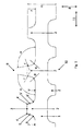
- Fig. 1 schematically shows a section of an enlarged scale EP 2 337 130 A1 known interconnector for a fuel cell stack in section.
- the interconnector has a plate-shaped main body 1 with elevations 2 on both opposite in the height direction 8 sides of the base body 1.
- the in section trapezoidal elevations 2 with the height h, which is knob-shaped over the entire extension of the interconnector, can be continuously web-shaped, or segmented web-shaped, form through their channel-like spaces between each two immediately adjacent elevations 2, the channels for the gas flow of the interconnector.
- the outer end contour 3 in the height direction 8 of each elevation 2 passes over a corner rounding 4 or 4 'with a corner radius r or r' into inclined side flanks with a straight flank section 5 or 5 '.
- the straight sections 5 and 5 'then go into curved sections 6 and 6' with a radius of curvature R and R ', respectively. These in turn then transition seamlessly into the surface contour 7 or 7 'of the main body 1.
- opposite end contours 3 limit a thickness D of the interconnector.
- the inclined side surfaces form an angle ⁇ or ⁇ 'with the surface contour 7 or 7' of the main body 1. It would also be conceivable that with curved sections 6 or 6 'with very large radii R and R' and small height dimensions h of the elevations 2, the corner roundings 4 and 4 'directly without the intermediate straight edge sections 5 and 5' in the curved sections 6 and 6 'open. In this case, the tangent in the transition from the corner roundings 4 or 4 'into the curved section 6 or 6' encloses the angle of inclination ⁇ or ⁇ 'with the surface contour 7' or 7 of the main body 1.
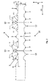
- a plurality of elevations 2 are arranged on a first side 9 and on a second side 10 of the main body 1 opposite the height direction 8. They are strung together in parallel to the base plane of the main body 1 extending row direction 11. Elevations 2 with a first geometry are arranged in a central portion 12 of the elevation row, while in a side facing away from the center of the elevation row outer portion 13 a plurality of elevations 2 are formed with a second geometry.
- two different geometries are realized on each side 9, 10 of the main body 1, wherein the first geometry on both sides 9, 10 and / or the second geometry on both sides 9, 10 do not have to be identical in each case.
- only one side 9 or 10 of the interconnector may have a second geometry in addition to the first geometry.
- the angle of inclination ⁇ 1 or ⁇ 1 'of the first geometry is 120 °.
- the inclination angle ⁇ 2 or ⁇ 2 'of the second geometry in the outer portion 13 is 135 °.
- the two side flanks 5 of the same elevation 2 preferably have an angle of inclination ⁇ 2 or ⁇ 2 'in an outer portion 13, which are different, in which case in particular the inclination angle ⁇ 2' facing the center of the elevation row or the central portion 12 is smaller than that one end of the elevation row or an outer portion 13 facing angle of inclination ⁇ 2.
- the outer end contours 3 of the elevations 2 lie in both elevation rows each in a plane which runs parallel to the ground plane of the main body 1.
- the height h1 of the elevations 2 in the central portion 12 is smaller than the height h2 in the outer portion 13.
- Molded parts were produced by powder metallurgy as interconnectors.
- the components were pressed such that at least a central portion of the two elevation rows 8 opposite elevation rows had a first geometry. While a bump row is associated with a cell cathode, the second bump row is associated with a cell anode.
- the two outer portions 13 of each survey series were three surveys 2 with a second geometry exists. 88% of the total number of surveys 2 had the first geometry. The most important geometric parameters of these interconnectors are reproduced below.
- interconnects showed a high degree of homogeneity of material density, i. a low density gradient, over all surveys along a survey series, so that in the production advantageously a single-stage pressing process is sufficient.
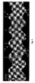
- FIG. 3 An example of a powder metallurgically produced interconnector is Fig. 3 removable. The two different geometries of the elevations 2 in an outer portion 13 and a central portion 12 of the survey series are clearly visible.
- a powder batch consisting of 95% by weight of Cr powder and 5% by weight of one was used to produce the molded parts with the abovementioned two geometries FeY master alloy (0.5 wt% Y alloy) was used.
- To this powder batch was added 1% by weight of pressing aid (wax). Thereafter, this powder batch was mixed in a tumble mixer for 15 minutes.
- a press tool was equipped with a press die according to the above-described different geometries. The pressed powder, that is the compact, was presintered at 1100 ° C for 20 minutes under a hydrogen atmosphere in a belt oven for the purpose of dewaxing.
- Fig. 4 shows schematically on an enlarged scale the detail of an end plate according to the invention for a fuel cell stack in section.
- the elevations (2) are in principle the same as in the interconnector Fig. 2 executed, unlike Fig. 3 However, viewed only on one side 10 of the body in the height direction 8.
Description
Die Erfindung betrifft ein Formteil mit den Merkmalen des Oberbegriffes des Patentanspruches 1.The invention relates to a molded part with the features of the preamble of
Aus
Die Herstellung der Endform derartiger Interkonnektoren und Endplatten durch spanabhebende Bearbeitung aus Halbzeug ist sehr kostenintensiv. Alternativ können die Formteile pulvermetallurgisch gefertigt werden, wobei pulverförmige Ausgangsmaterialien möglichst in die Endform gepresst und anschließend gesintert werden.The production of the final form of such interconnectors and end plates by machining semi-finished products is very costly. Alternatively, the moldings can be made by powder metallurgy, powdered starting materials are pressed as possible into the final shape and then sintered.
Bei der geometrischen Auslegung der Querschnitte (d.h. die Zwischenräume zwischen aneinander gereihten Erhebungen) für die Gasführung wären an sich rechteckige Querschnitte optimal, da sie einen guten Kompromiss im Hinblick auf maximale Kontaktierungsfläche bei gleichzeitig ausreichend großem Querschnitt für die Gasführung bilden. Derartige Formen sind jedoch auf pulvermetallurgischem Wege praktisch nicht herstellbar, so dass sich in der Praxis trapezförmige Querschnitte mit geraden, geneigten Flanken durchgesetzt haben. Diese Flanken sind bei der pulvermetallurgischen Herstellung üblicherweise mittels kleiner Übergangsradien einerseits mit einer in Höhenrichtung äußeren Endkontur der Erhebung (Eckenradius) und andererseits mit der Oberflächenkontur des Grundkörpers (Kurvenradius) verbunden, wobei ein gerader Flankenabschnitt der Flanke oder eine im Punkt des Übergangs beider Übergangsradien derselben Flanke liegende Tangente in einem Neigungswinkel zur Grundebene des Grundkörpers angeordnet ist.In the geometric design of the cross sections (ie, the spaces between juxtaposed surveys) for the gas guide rectangular cross sections would be optimal, since they form a good compromise in terms of maximum contact area at the same time sufficiently large cross section for the gas guide. However, such forms are on powder metallurgical ways virtually impossible to produce, so that in practice trapezoidal cross sections have prevailed with straight, inclined flanks. These flanks are usually connected in powder metallurgy production by means of small transition radii on the one hand with an outer end contour of the elevation (corner radius) in the height direction and on the other hand with the surface contour of the base body (curve radius), wherein a straight flank portion of the flank or one at the point of transition both transition radii Flank lying tangent is arranged at an inclination angle to the ground plane of the base body.
Der Erfindung liegt die Aufgabe zugrunde, das Formteil für eine fertigungstechnisch einfache und prozesssichere Herstellung anzupassen.The invention has for its object to adapt the molding for a manufacturing technology simple and process-reliable production.
Diese Aufgabe wird durch die Merkmalskombination des unabhängigen Patentanspruches 1 gelöst.This object is achieved by the combination of features of
Erfindungsgemäß wird dies dadurch erreicht, dass mindestens zwei unterschiedliche Neigungswinkel an derselben Seite des Grundkörpers vorhanden sind, wobei unterschiedliche Neigungswinkel auch unterschiedliche Geometrien der jeweils zugeordneten Erhebungen repräsentieren. Auf diese Weise sind mindestens eine erste Geometrie und eine zweite Geometrie vorhanden. Auf überraschende Weise wurde erkannt, dass eine Kombination von mindestens zwei unterschiedlichen Neigungswinkeln auf einer Seite des Grundkörpers von Fertigungswerkzeugen bzw. Presswerkzeugen vorteilhaft genutzt werden kann, um einerseits die geforderte hohe Materialdichte mit einem geringen Dichtegradienten, also eine große Homogenität, des fertigen Formteiles für die zuverlässige Gastrennung zu erreichen und andererseits eine prozesssichere und störungsfreie Entformung des Bauteils zu erzielen. Hierdurch lässt sich eine zuverlässige Gastrennung durch das Formteil erzielen bei gleichzeitig begrenzter Komplexität des Fertigungswerkzeuges. Dies gilt insbesondere für die pulvermetallurgische Herstellung mittels Pressen und Sintern. Hierdurch ergibt sich auch die Möglichkeit, bei der pulvermetallurgischen Herstellung ein kostengünstiges einstufiges Pressverfahren anzuwenden, um die hohe und gleichmäßige Dichte des Formteiles bereits mit einem einzigen Pressvorgang zu erzielen. Dies ist herkömmlich bei Formteilen vielfach nicht möglich, insbesondere wenn es sich um Interkonnektoren und Endplatten handelt, die bei oxidkeramischen Hochtemperaturbrennstoffzellenstapeln (solid oxide fuel cell bzw. SOFC) zum Einsatz kommen und vielfach Legierungen mit hohen Chromanteilen als Werkstoff enthalten. Derartige Legierungen sind aber bei niedrigen Temperaturen äußerst spröde und können nur sehr schwer verpresst werden oder müssen über ein kostenaufwändiges, mehrstufiges Pressverfahren bearbeitet werden.According to the invention, this is achieved by virtue of the fact that at least two different angles of inclination are present on the same side of the base body, wherein different angles of inclination also represent different geometries of the respectively associated elevations. In this way, at least a first geometry and a second geometry are present. In a surprising manner, it was recognized that a combination of at least two different angles of inclination on one side of the main body of production tools or pressing tools can be advantageously used, on the one hand the required high material density with a low density gradient, ie a high degree of homogeneity of the finished molded part for the To achieve reliable gas separation and on the other hand to achieve a process-safe and trouble-free demoulding of the component. This makes it possible to achieve reliable gas separation through the molded part while at the same time limiting the complexity of the production tool. This applies in particular to powder metallurgy production by means of pressing and sintering. This also gives the possibility to apply in the powder metallurgical production of a cost-effective single-stage pressing process to the high and uniform density of To achieve molding already with a single pressing operation. This is conventionally often not possible with molded parts, in particular when it comes to interconnectors and end plates that are used in oxide-ceramic high-temperature fuel cell stacks (solid oxide fuel cell or SOFC) and often contain alloys with high chromium contents as a material. Such alloys, however, are extremely brittle at low temperatures and can only be pressed with great difficulty or have to be processed via a costly, multistage pressing process.
Unterschiedliche Neigungswinkel bieten die Möglichkeit, das Presswerkzeug für die pulvermetallurgische Herstellung geometrisch derart anzupassen, dass ein verbessertes Entformen des Presslings aus dem Presswerkzeug ohne störende Reibungskräfte zwischen den Oberflächen des Presslings, insbesondere seiner Erhebungen, und dem Presswerkzeug selbst erzielt wird. Relativbewegungen zwischen der Negativform des Fertigungswerkzeuges und dem zu pressenden Formteil bleiben fertigungstechnisch vorteilhaft ohne Einfluss auf die definierte Endgeometrie und mechanische Integrität des Bauteils, wobei die Pressdichte sowie der Pressdichtegradient des Formteiles weiterhin in ausreichendem Maß bereitgestellt sind. Die unterschiedlichen Neigungswinkel tragen somit zu einem qualitativ besonders hochwertigen Formteil bei. Die Positionierung der Erhebungen mit unterschiedlichen Geometrien kann in Reihenrichtung abhängig vom verwendeten Fertigungswerkzeug, insbesondere Presswerkzeug oder Pressstempel, individuell definiert werden. Die Anzahl fehlerhafter Formteile ist reduziert. Demgegenüber ist die Berücksichtigung unterschiedlicher definierter Geometrien an dem Fertigungswerkzeug verhältnismäßig kostengünstig realisierbar.Different angles of inclination offer the possibility of geometrically adjusting the pressing tool for powder metallurgy production in such a way that improved removal of the compact from the pressing tool is achieved without disturbing frictional forces between the surfaces of the compact, in particular its elevations, and the pressing tool itself. Relative movements between the negative mold of the production tool and the molded part to be pressed remain advantageous in terms of production engineering without influencing the defined final geometry and mechanical integrity of the component, wherein the compactness and the compactness of the molded part are still provided to a sufficient extent. The different angles of inclination thus contribute to a particularly high-quality molded part. The positioning of the elevations with different geometries can be defined individually in the row direction depending on the production tool used, in particular pressing tool or press die. The number of defective moldings is reduced. In contrast, the consideration of different defined geometries on the production tool can be realized relatively inexpensively.
Das Entformen zwischen Pressling und Presswerkzeug kann in vielen Anwendungsfällen zusätzlich verbessert werden, wenn der Neigungswinkel der zweiten Geometrie größer ist als der Neigungswinkel der ersten Geometrie.The demoulding between compact and pressing tool can be further improved in many applications, if the inclination angle of the second geometry is greater than the inclination angle of the first geometry.
Die erste Geometrie ist vorzugsweise durch mindestens einen der folgenden physikalischen Parameter und dessen Werte repräsentiert:
- Der Neigungswinkel α1, α1' liegt im Bereich von 95° bis 135°, insbesondere 95° bis 120° und weiter bevorzugt 95° bis 110°.
- Der Kurvenradius R1, R1' liegt im Bereich von 0,15 bis 1 mm, insbesondere 0,3 bis 1 mm.
- Das Verhältnis des Kurvenradius R1, R1' zur Höhe h (R : h) liegt in einem Bereich von 0,25 bis 1, insbesondere 0,5 bis 1, weiter bevorzugt 0,7 bis 1.
- The inclination angle α1, α1 'is in the range of 95 ° to 135 °, in particular 95 ° to 120 ° and more preferably 95 ° to 110 °.
- The radius of curvature R1, R1 'is in the range of 0.15 to 1 mm, in particular 0.3 to 1 mm.
- The ratio of the radius of curvature R1, R1 'to the height h (R: h) is in a range of 0.25 to 1, in particular 0.5 to 1, more preferably 0.7 to 1.
Abgesehen von unterschiedlichen Neigungswinkeln können die bereitgestellten unterschiedlichen Geometrien auch unterschiedliche Kurvenradien und/oder unterschiedliche Höhen für eine oder mehrere Erhebungen aufweisen. Vorzugsweise sind die Eckenrundungen zwischen äußerer Endkontur der Erhebung und der Seitenflanke mit einem Eckenradius r ausgestattet. In diesem Fall besteht eine weitere Möglichkeit zur Bereitstellung unterschiedlicher Geometrien darin, unterschiedliche Eckenradien r zu definieren.Apart from different angles of inclination, the different geometries provided can also have different curve radii and / or different heights for one or more elevations. Preferably, the corner curves between outer end contour of the survey and the side edge are equipped with a corner radius r. In this case, another way to provide different geometries is to define different corner radii r.
Die Ansprüche 3 bis 5 schlagen geeignete Neigungswinkel vor, welche die Realisierung der geforderten Dichte und Homogenität des Formteiles zusätzlich unterstützen. Bei verhältnismäßig großen Neigungswinkeln weist die Erhebung relativ flache Seitenflanken auf. Die hierdurch möglicherweise bedingte Verkleinerung des Kanalquerschnittes zwischen zwei unmittelbar benachbarten Erhebungen zur Gasführung kann durch eine entsprechend abgewandelte Dimensionierung anderer Parameter der Geometrie, insbesondere der Höhe und/oder des Eckenradius und/oder des Kurvenradius ausgeglichen werden.The
Gemäß den Ansprüchen 6 und 7 ist mindestens eine Erhebung im Querschnitt asymmetrisch ausgebildet. Hierdurch werden etwaige Scherbelastungen durch Relativbewegungen zwischen Presswerkzeug und dem Pressling (also dem zu formenden Formteil) z.B. beim Entformen vermieden. Somit wird die geforderte Gasdichtheit über die gesamte Querschnittsfläche des Grundkörpers hinweg zusätzlich unterstützt.According to
Vorzugsweise weisen mindestens 50%, insbesondere mindestens 70%, der Gesamtzahl der in Reihenrichtung aneinandergereihten Erhebungen einer Seite des Grundkörpers eine erste Geometrie auf (Ansprüche 8 und 9). Abhängig von dem verwendeten Presswerkzeug und/oder der Größe des Grundkörpers in seiner Grundebene können bereits einzelne Erhebungen mit einer zweiten Geometrie ausreichend sein, um zuverlässig eine gleichmäßige Pressdichte für alle Erhebungen zu erzielen und gleichzeitig eine gute Entformbarkeit zu gewährleisten.Preferably, at least 50%, in particular at least 70%, of the total number of aligned in the row direction elevations of a page of the basic body to a first geometry (
Die Ansprüche 10 und 11 schlagen entlang der Reihenrichtung mehrere unmittelbar benachbarte Erhebungen mit derselben Geometrie vor. Hierdurch kann das Presswerkzeug gezielt an unterschiedliche Segmente des Grundkörpers angepasst werden, um störende Einflüsse während des Pressens und Entformens zu vermeiden.The
Vorzugsweise ist die zweite Geometrie an mindestens einer Erhebung realisiert, die in einem äußeren Abschnitt der Erhebungs-Reihe einer Seite des Grundkörpers angeordnet ist (Anspruch 12). Dies unterstützt eine kostengünstige Herstellung von Formteilen mit größerem Platten- oder Scheibenquerschnitt in der Grundebene des Grundkörpers, wenn die geforderte hohe Dichte mit geringem Dichtegradienten vor allem bei längeren Erhebungs-Reihen in äußeren Abschnitten der Reihenrichtung sichergestellt werden soll.Preferably, the second geometry is realized on at least one elevation, which is arranged in an outer portion of the elevation row one side of the base body (claim 12). This supports a cost-effective production of molded parts with a larger plate or disk cross-section in the ground plane of the body, if the required high density with low density gradient is to be ensured especially in longer elevation rows in outer sections of the row direction.
Die Ansprüche 13 bis 15 schlagen bevorzugte Maßnahmen und Bereiche für die Ausbildung der Geometrie-Parameter Höhe und Kurvenradius vor. Hierdurch kann der durch größere Neigungswinkel und somit flachere Seitenflanken zunächst reduzierte Kanalquerschnitt im Bereich der zweiten Geometrie zumindest wieder soweit ausgeglichen werden, dass er zumindest dem Kanalquerschnitt im Bereich der ersten Geometrie entspricht. Trotz der geometrischen Veränderung des Formteiles gegenüber herkömmlichen Bauteilen wird deshalb die Gasführungs-Leistungsfähigkeit aufrechterhalten, wenn das Formteil z.B. bei einer Brennstoffzelle eingesetzt wird.
Anspruch 16 schlägt bevorzugte Anwendungsmöglichkeiten des erfindungsgemäßen Formteiles vor. Sowohl beim Interkonnektor als auch bei der Endplatte handelt es sich um sogenannte Stromsammler. Der Interkonnektor ist üblicherweise zwischen zwei Zellen eines Zellenstapels angeordnet, während die Endplatte an einem Ende des Zellenstapels angeordnet ist. Mindestens eine der beiden Grundkörperseiten (anodenseitig und/oder kathodenseitig) des Formteiles weist eine Erhebungs-Reihe mit mindestens zwei unterschiedlichen Geometrien auf. Die mittels der unterschiedlichen Geometrien fertigungstechnisch einfach sichergestellte Gasdichtheit des Interkonnektors bzw. der Endplatte verbessert auf kostengünstige Weise das Langzeitverhalten und die Leistungsfähigkeit des Zellenstapels. Bei der elektrochemischen Zelle handelt es sich insbesondere um eine Festelektrolyt-Brennstoffzelle - auch SOFC (Solid Oxid Fuel Cell) genannt - oder um eine Zelle für Elektrolyseanwendungen, insbesondere Hochtemperaturelektrolyse.Claim 16 proposes preferred applications of the molding according to the invention. Both the interconnector and the end plate are so-called current collectors. Of the The interconnector is usually located between two cells of a cell stack, while the end plate is located at one end of the cell stack. At least one of the two main body sides (anode-side and / or cathode-side) of the molded part has a raised row with at least two different geometries. The gas tightness of the interconnector or the end plate, which is easily ensured by means of the different geometries, improves the long-term behavior and the efficiency of the cell stack in a cost-effective manner. The electrochemical cell is in particular a solid electrolyte fuel cell - also known as SOFC (solid oxide fuel cell) - or a cell for electrolysis applications, in particular high-temperature electrolysis.
Die Erfindung wird anhand der in den Zeichnungen dargestellten Ausführungsbeispiele näher erläutert. Es zeigen:
- Fig. 1:
- eine maßstäblich vergrößerte, schematische und geschnittene Seitenansicht eines Ausschnittes eines vorbekannten Interkonnektors,
- Fig. 2:
- eine maßstäblich vergrößerte, schematische und geschnittene Seitenansicht eines Ausschnittes eines erfindungsgemäßen Interkonnektors,
- Fig. 3:
- eine rasterelektronenmikroskopische Aufnahme eines Querschliffes eines erfindungsgemäßen Interkonnektors,
- Fig. 4:
- eine maßstäblich vergrößerte, schematische und geschnittene Seitenansicht eines Ausschnittes einer erfindungsgemäßen Endplatte.
- Fig. 1:
- an enlarged scale, schematic and sectioned side view of a section of a prior art interconnector,
- Fig. 2:
- an enlarged scale, schematic and sectioned side view of a section of an interconnector according to the invention,
- 3:
- a scanning electron micrograph of a transverse section of an interconnector according to the invention,
- 4:
- an enlarged scale, schematic and sectioned side view of a section of an end plate according to the invention.
Bei dem ausschnittsweise im Querschnitt schematisch dargestellten Interkonnektor gemäß
Alternativ kann auch nur eine Seite 9 oder 10 des Interkonnektors neben der ersten Geometrie eine zweite Geometrie aufweisen.Alternatively, only one
In
In
Die äußeren Endkonturen 3 der Erhebungen 2 liegen bei beiden Erhebungs-Reihen jeweils in einer Ebene, welche parallel zur Grundebene des Grundkörpers 1 verläuft. Gleichzeitig ist die Höhe h1 der Erhebungen 2 im zentralen Abschnitt 12 kleiner als die Höhe h2 in dem äußeren Abschnitt 13. Mit anderen Worten sind die entsprechenden Oberflächenkonturen 7 des Grundkörpers 1 im Bereich des äußeren Abschnittes 13 einerseits und im Bereich des zentralen Abschnittes 12 andererseits in Höhenrichtung 8 versetzt angeordnet.The
Es wurden Formteile als Interkonnektoren pulvermetallurgisch hergestellt. Mittels eines Presswerkzeugs wurden die Bauteile derart gepresst, dass zumindest ein zentraler Abschnitt der beiden in Höhenrichtung 8 gegenüberliegenden Erhebungs-Reihen eine erste Geometrie aufwies. Während eine Erhebungs-Reihe einer Zellen-Kathode zugeordnet ist, ist die zweite Erhebungs-Reihe einer Zellen-Anode zugeordnet. An den beiden äußeren Abschnitten 13 jeder Erhebungs-Reihe waren drei Erhebungen 2 mit einer zweiten Geometrie vorhanden. 88% der Gesamtanzahl der Erhebungen 2 wiesen die erste Geometrie auf. Die wichtigsten geometrischen Parameter dieser Interkonnektoren sind nachfolgend wiedergegeben.Molded parts were produced by powder metallurgy as interconnectors. By means of a pressing tool, the components were pressed such that at least a central portion of the two
Kathodenseitig wurden für die Erhebungen 2 folgende Geometrien realisiert:
Anodenseitig wurden für die Erhebungen 2 folgende Geometrien realisiert:
Derart ausgebildete Interkonnektoren zeigten einen hohen Grad an Homogenität der Materialdichte, d.h. einen geringen Dichtegradienten, über sämtliche Erhebungen entlang einer Erhebungs-Reihe hinweg, so dass bei der Herstellung vorteilhaft ein einstufiges Pressverfahren ausreichend ist.Thus formed interconnects showed a high degree of homogeneity of material density, i. a low density gradient, over all surveys along a survey series, so that in the production advantageously a single-stage pressing process is sufficient.
Ein Beispiel für einen pulvermetallurgisch hergestellten Interkonnektor ist
Zur Herstellung der Formteile mit den vorgenannten beiden Geometrien wurde z.B. ein Pulveransatz bestehend aus 95 Gew.-% Cr-Pulver und 5 Gew.-% einer FeY-Vorlegierung (Legierung mit 0,5 Gew.-% Y) verwendet. Diesem Pulveransatz wurde 1 Gew.-% Presshilfsmittel (Wachs) hinzugegeben. Danach wurde dieser Pulveransatz in einem Taumelmischer 15 Minuten gemischt. Ein Presswerkzeug wurde mit einem Pressstempel entsprechend der vorbeschriebenen unterschiedlichen Geometrien ausgestattet. Das gepresste Pulver, also der Pressling wurde bei 1100°C für 20 Minuten unter Wasserstoffatmosphäre in einem Bandofen zum Zweck der Entwachsung vorgesintert. Danach erfolgte ein Hochtemperatur-Sintern des Bauteiles bei 1400°C für 7 Stunden unter Wasserstoffatmosphäre zum Zweck einer weiteren Verdichtung und Legierungsbildung. Daraufhin erfolgte eine Voroxidation des Bauteils bei 950°C für eine Zeitdauer von 10 bis 30 Stunden, um eventuell vorhandene Restporosität soweit zu verschließen, dass die Permeabilität des Materials ausreichend niedrig ist. Anschließend wurden die Oberflächen des Bauteils durch einen allseitigen Sandstrahlprozess von der Oxidschicht befreit.For example, a powder batch consisting of 95% by weight of Cr powder and 5% by weight of one was used to produce the molded parts with the abovementioned two geometries FeY master alloy (0.5 wt% Y alloy) was used. To this powder batch was added 1% by weight of pressing aid (wax). Thereafter, this powder batch was mixed in a tumble mixer for 15 minutes. A press tool was equipped with a press die according to the above-described different geometries. The pressed powder, that is the compact, was presintered at 1100 ° C for 20 minutes under a hydrogen atmosphere in a belt oven for the purpose of dewaxing. This was followed by a high-temperature sintering of the component at 1400 ° C for 7 hours under a hydrogen atmosphere for the purpose of further compression and alloying. This was followed by a pre-oxidation of the component at 950 ° C for a period of 10 to 30 hours to close any residual porosity so far that the permeability of the material is sufficiently low. Subsequently, the surfaces of the component were freed from the oxide layer by an all-round sandblasting process.
Claims (16)
- A powder metallurgical molded part comprising a disk-like or plate-like main body (1) and a multiplicity of knob-shaped and/or ridge-shaped elevations (2) which are arranged next to one another in a row direction (11) and thereby form a row and which have a height (h1, h2) perpendicular to the main plane of the main body (1) and which each have a cross section with two side flanks, which lead from an outer end contour (3), as seen in the height direction (8), of the elevation (2) via rounded corner portions (4, 4') into curved portions (6, 6') with a curve radius (R, R'), wherein the curve radius (R, R') merges into the surface contour (7) of the main body (1), wherein- a rectilinear flank portion (5) of the side flank or- a tangent of the side flank lying at the point where the rounded corner portion (4) merges into the curved portion (6)is arranged at an angle of inclination (α1, α1') with respect to the main plane of the main body (1), and wherein elevations (2) are arranged on at least one side (9, 10) of the two sides (9, 10) of the main body (1) which lie opposite one another in the height direction (8),
characterized in that
at least two different angles of inclination (α1, α1'; α2, α2') are present on the same side (9, 10) of the main body (1), wherein the at least two different angles of inclination (α1, α1'; α2, α2') represent at least a first geometry (h1, r1, r1', R1, R1', α1, α1') and a second geometry (h2, r2, r2', R2, R2', α2, α2'). - The molded part as claimed in claim 1, characterized in that
the angle of inclination (α2, α2') of the second geometry (h2, r2, r2', R2, R2', α2, α2') is larger than the angle of inclination (α1, α1') of the first geometry (h1, r1, r1', R1, R1', α1, α1'). - The molded part as claimed in either of the preceding claims, characterized in that
the angle of inclination (α1, α1') of the first geometry (h1, r1, r1', R1, R1', α1, α1') lies in a range of 95° to 135°. - The molded part as claimed in one of the preceding claims, characterized in that
the angle of inclination (α2, α2') of the second geometry (h2, r2, r2', R2, R2', α2, α2') lies in a range of 135° to 150°. - The molded part as claimed in one of the preceding claims, characterized in that
side flanks of adjacent elevations (2) have different angles of inclination (α1, α1'; α2, α2'). - The molded part as claimed in one of the preceding claims, characterized in that
the two side flanks of the same elevation (2) have different angles of inclination (α1, α1'; α2, α2'). - The molded part as claimed in claim 6, characterized in that
the side flank facing toward an end (13) of the row of elevations in the row direction (11) has a greater angle of inclination (α2) than the side flank facing toward the center (12) of the row of elevations. - The molded part as claimed in one of the preceding claims, characterized in that
at most 50% of the total number of elevations (2) have the second geometry (h2, r2, r2', R2, R2', α2, α2'). - The molded part as claimed in claim 8, characterized in that
at most 30% of the total number of elevations (2) have the second geometry (h2, r2, r2', R2, R2', α2, α2'). - The molded part as claimed in one of the preceding claims, characterized in that
the first geometry (h1, r1, r1', R1, R1', α1, α1') and/or the second geometry (h2, r2, r2', R2, R2', α2, α2') is present at a plurality of directly adjacent elevations (2) along the row direction (11) of the row of elevations. - The molded part as claimed in claim 10, characterized in that
the directly adjacent elevations (2) of the first geometry (h1, r1, r1', R1, R1', α1, α1') are arranged in a central portion (12) of the row of elevations. - The molded part as claimed in one of the preceding claims, characterized in that
an outer portion (13) of the row of elevations remote from the center of the row of elevations has at least one elevation (2) with the second geometry (h2, r2, r2', R2, R2', α2, α2'). - The molded part as claimed in one of the preceding claims, characterized in that
the elevation (2) of the first geometry (h1, r1, r1', R1, R1', α1, α1') has a height (h1) which is smaller than the height (h2) of an elevation (2) of the second geometry (h2, r2, r2', R2, R2', α2, α2'). - The molded part as claimed in one of the preceding claims, characterized in that
the curve radius (R2, R2') of an elevation (2) of the second geometry (h2, r2, r2', R2, R2', α2, α2') is smaller than 0.15 mm. - The molded part as claimed in one of the preceding claims, characterized in that
the ratio of curve radius (R2, R2') to height (h2) R : h of an elevation (2) of the second geometry (h2, r2, r2', R2, R2', α2, α2') is less than 0.25. - The molded part as claimed in one of the preceding claims, characterized in that
the molded part is an interconnector or an end plate for electrically connecting electrochemical cells.
Applications Claiming Priority (2)
| Application Number | Priority Date | Filing Date | Title |
|---|---|---|---|
| ATGM412/2011U AT12696U1 (en) | 2011-07-21 | 2011-07-21 | MOLDING |
| PCT/AT2012/000191 WO2013010198A1 (en) | 2011-07-21 | 2012-07-18 | Molded part |
Publications (2)
| Publication Number | Publication Date |
|---|---|
| EP2734323A1 EP2734323A1 (en) | 2014-05-28 |
| EP2734323B1 true EP2734323B1 (en) | 2015-10-28 |
Family
ID=47048856
Family Applications (1)
| Application Number | Title | Priority Date | Filing Date |
|---|---|---|---|
| EP12755946.6A Active EP2734323B1 (en) | 2011-07-21 | 2012-07-18 | Molded part |
Country Status (10)
| Country | Link |
|---|---|
| US (1) | US9472816B2 (en) |
| EP (1) | EP2734323B1 (en) |
| JP (1) | JP6025842B2 (en) |
| KR (1) | KR101880787B1 (en) |
| CN (1) | CN103917314B (en) |
| AT (1) | AT12696U1 (en) |
| CA (1) | CA2842044C (en) |
| DK (1) | DK2734323T3 (en) |
| IN (1) | IN2014DN00191A (en) |
| WO (1) | WO2013010198A1 (en) |
Families Citing this family (7)
| Publication number | Priority date | Publication date | Assignee | Title |
|---|---|---|---|---|
| AT513501B1 (en) * | 2013-09-02 | 2014-05-15 | Abatec Group Ag | IR emitter with double glazing |
| US9992917B2 (en) | 2014-03-10 | 2018-06-05 | Vulcan GMS | 3-D printing method for producing tungsten-based shielding parts |
| US20180248203A1 (en) * | 2017-02-28 | 2018-08-30 | GM Global Technology Operations LLC | System and method for manufacturing channels in a bipolar plate |
| AU2020315120A1 (en) | 2019-07-17 | 2022-02-24 | Haldor Topsøe A/S | A method for chromium upgrading of ferritic steel interconnects for solid oxide cell stack applications |
| CN112317577A (en) * | 2020-10-15 | 2021-02-05 | 贵州航天精工制造有限公司 | Device for locking screw sleeve single-point closing in and using method |
| FR3127639B1 (en) * | 2021-09-29 | 2023-10-27 | Commissariat Energie Atomique | Interconnector for stacking of SOEC/SOFC type solid oxide cells comprising different raised elements |
| FR3127640B1 (en) * | 2021-09-29 | 2023-10-27 | Commissariat Energie Atomique | Interconnector for stacking SOEC/SOFC type solid oxide cells with optimized geometry tabs |
Family Cites Families (13)
| Publication number | Priority date | Publication date | Assignee | Title |
|---|---|---|---|---|
| JPH0670161A (en) | 1992-08-21 | 1994-03-11 | Sharp Corp | Image forming device |
| JPH0670161U (en) * | 1993-03-15 | 1994-09-30 | 三菱重工業株式会社 | Flat plate solid oxide fuel cell |
| JPH1040937A (en) * | 1996-07-18 | 1998-02-13 | Toyota Motor Corp | Manufacture of collector for fuel cell, and manufacturing device therefor |
| JP2000021423A (en) * | 1998-07-03 | 2000-01-21 | Tokai Carbon Co Ltd | Separator for fuel cell and manufacture thereof |
| WO2000055931A1 (en) * | 1999-03-15 | 2000-09-21 | Case Western Reserve University | Metal sponges for rapid surface-chemical reactions |
| US6298685B1 (en) * | 1999-11-03 | 2001-10-09 | Applied Materials, Inc. | Consecutive deposition system |
| AT4737U1 (en) * | 2001-01-15 | 2001-11-26 | Plansee Ag | POWDER METALLURGICAL METHOD FOR PRODUCING HIGH-DENSITY MOLDED PARTS |
| JP2003223856A (en) * | 2002-01-30 | 2003-08-08 | Canon Inc | Electron beam equipment and spacer |
| KR100437498B1 (en) * | 2002-02-04 | 2004-06-25 | 한국에너지기술연구원 | Anode-supported tubular solid oxide fuel cell stack and fabrication method of it |
| AT6260U1 (en) * | 2002-08-01 | 2003-07-25 | Plansee Ag | METHOD FOR PRODUCING A MOLDED PART |
| JP2006062103A (en) * | 2004-08-24 | 2006-03-09 | Honda Motor Co Ltd | Mold for injection-molding fuel cell separator and fuel cell separator |
| GB0918042D0 (en) * | 2009-10-15 | 2009-12-02 | Delphi Tech Inc | Connector assembly and method of manufacturing same |
| AT11799U1 (en) * | 2009-12-15 | 2011-05-15 | Plansee Se | MOLDING |
-
2011
- 2011-07-21 AT ATGM412/2011U patent/AT12696U1/en not_active IP Right Cessation
-
2012
- 2012-07-18 EP EP12755946.6A patent/EP2734323B1/en active Active
- 2012-07-18 DK DK12755946.6T patent/DK2734323T3/en active
- 2012-07-18 JP JP2014520461A patent/JP6025842B2/en active Active
- 2012-07-18 CN CN201280036180.8A patent/CN103917314B/en active Active
- 2012-07-18 KR KR1020147001366A patent/KR101880787B1/en active IP Right Grant
- 2012-07-18 US US14/234,037 patent/US9472816B2/en active Active
- 2012-07-18 WO PCT/AT2012/000191 patent/WO2013010198A1/en active Application Filing
- 2012-07-18 IN IN191DEN2014 patent/IN2014DN00191A/en unknown
- 2012-07-18 CA CA2842044A patent/CA2842044C/en active Active
Also Published As
| Publication number | Publication date |
|---|---|
| CA2842044A1 (en) | 2013-01-24 |
| KR101880787B1 (en) | 2018-07-20 |
| US20140147692A1 (en) | 2014-05-29 |
| CA2842044C (en) | 2019-02-26 |
| US9472816B2 (en) | 2016-10-18 |
| CN103917314A (en) | 2014-07-09 |
| KR20140044368A (en) | 2014-04-14 |
| CN103917314B (en) | 2015-12-09 |
| EP2734323A1 (en) | 2014-05-28 |
| IN2014DN00191A (en) | 2015-06-05 |
| JP6025842B2 (en) | 2016-11-16 |
| AT12696U1 (en) | 2012-10-15 |
| WO2013010198A1 (en) | 2013-01-24 |
| DK2734323T3 (en) | 2016-02-08 |
| JP2014525988A (en) | 2014-10-02 |
Similar Documents
| Publication | Publication Date | Title |
|---|---|---|
| EP2734323B1 (en) | Molded part | |
| EP2337130B1 (en) | Moulded part | |
| DE102004038870B4 (en) | Solid oxide fuel cell stack and method of producing the solid oxide fuel cell stack | |
| DE102018102314B4 (en) | Matrix arrangement for an embossing press | |
| EP2154742B1 (en) | Fuel cell unit and method for producing an electrically conductive connection between an electrode and a bipolar plate | |
| AT6260U1 (en) | METHOD FOR PRODUCING A MOLDED PART | |
| EP3378117B1 (en) | Bipolar plate having asymmetrical sealing sections, and fuel cell stack having such a bipolar plate | |
| DE102011088105B4 (en) | END PLATE FOR A FUEL CELL WITH A SANDWICH INSERT | |
| EP2230707A1 (en) | Interconnector of a solid electrolyte high temperature fuel cell | |
| DE102007034967A1 (en) | Fuel cell and process for its production | |
| DE102008041320A1 (en) | Fuel cell separator and method of making the same | |
| EP0142030A2 (en) | Electrochemical storage cell | |
| WO2004112178A2 (en) | Electrochemical arrangement comprising an elastic distribution structure | |
| DE102011000180A1 (en) | Anode-supported flat tube SOFC and its manufacturing process | |
| AT15921U1 (en) | Porous molding for electrochemical module | |
| DE112009002448B4 (en) | fuel cell | |
| EP3031093B1 (en) | Method for producing a fuel cell and a fuel cell system | |
| DE19832625A1 (en) | Process for producing a stacked reactor and catalyst disk for a stacked reactor | |
| EP3042413B1 (en) | Body from metallurgic powder as interconnector or endplatte for an electrochemical cell | |
| WO2021198137A1 (en) | Method for producing a gas- and/or electron-conducting structure and fuel/electrolysis cell | |
| EP1340282B1 (en) | Fuel cell assembly | |
| DE102006041296A1 (en) | Plate unit for e.g. current collector plate of polymer electrolyte membrane fuel cell, has channel structure with channels, where each channel has inner geometry with different characteristic values for different channel sections | |
| EP2850687B1 (en) | Electrical energy store | |
| DE102022104124B3 (en) | Electrochemical cell electrode and method of making an electrode | |
| DE102005027065B4 (en) | Spacer arrangement and fuel cell unit for a fuel cell stack |
Legal Events
| Date | Code | Title | Description |
|---|---|---|---|
| PUAI | Public reference made under article 153(3) epc to a published international application that has entered the european phase |
Free format text: ORIGINAL CODE: 0009012 |
|
| 17P | Request for examination filed |
Effective date: 20140113 |
|
| AK | Designated contracting states |
Kind code of ref document: A1 Designated state(s): AL AT BE BG CH CY CZ DE DK EE ES FI FR GB GR HR HU IE IS IT LI LT LU LV MC MK MT NL NO PL PT RO RS SE SI SK SM TR |
|
| RIN1 | Information on inventor provided before grant (corrected) |
Inventor name: HIRSCH, OLIVER Inventor name: LEITER, THOMAS Inventor name: BRANDNER, MARCO Inventor name: KRAUSSLER, WOLFGANG |
|
| DAX | Request for extension of the european patent (deleted) | ||
| GRAP | Despatch of communication of intention to grant a patent |
Free format text: ORIGINAL CODE: EPIDOSNIGR1 |
|
| INTG | Intention to grant announced |
Effective date: 20150610 |
|
| GRAS | Grant fee paid |
Free format text: ORIGINAL CODE: EPIDOSNIGR3 |
|
| GRAA | (expected) grant |
Free format text: ORIGINAL CODE: 0009210 |
|
| AK | Designated contracting states |
Kind code of ref document: B1 Designated state(s): AL AT BE BG CH CY CZ DE DK EE ES FI FR GB GR HR HU IE IS IT LI LT LU LV MC MK MT NL NO PL PT RO RS SE SI SK SM TR |
|
| REG | Reference to a national code |
Ref country code: GB Ref legal event code: FG4D Free format text: NOT ENGLISH |
|
| REG | Reference to a national code |
Ref country code: CH Ref legal event code: EP |
|
| REG | Reference to a national code |
Ref country code: AT Ref legal event code: REF Ref document number: 757643 Country of ref document: AT Kind code of ref document: T Effective date: 20151115 |
|
| REG | Reference to a national code |
Ref country code: IE Ref legal event code: FG4D Free format text: LANGUAGE OF EP DOCUMENT: GERMAN |
|
| REG | Reference to a national code |
Ref country code: SE Ref legal event code: TRGR |
|
| REG | Reference to a national code |
Ref country code: DE Ref legal event code: R096 Ref document number: 502012005109 Country of ref document: DE |
|
| REG | Reference to a national code |
Ref country code: DK Ref legal event code: T3 Effective date: 20160201 |
|
| REG | Reference to a national code |
Ref country code: LT Ref legal event code: MG4D |
|
| REG | Reference to a national code |
Ref country code: NL Ref legal event code: MP Effective date: 20151028 |
|
| PG25 | Lapsed in a contracting state [announced via postgrant information from national office to epo] |
Ref country code: HR Free format text: LAPSE BECAUSE OF FAILURE TO SUBMIT A TRANSLATION OF THE DESCRIPTION OR TO PAY THE FEE WITHIN THE PRESCRIBED TIME-LIMIT Effective date: 20151028 Ref country code: LT Free format text: LAPSE BECAUSE OF FAILURE TO SUBMIT A TRANSLATION OF THE DESCRIPTION OR TO PAY THE FEE WITHIN THE PRESCRIBED TIME-LIMIT Effective date: 20151028 Ref country code: ES Free format text: LAPSE BECAUSE OF FAILURE TO SUBMIT A TRANSLATION OF THE DESCRIPTION OR TO PAY THE FEE WITHIN THE PRESCRIBED TIME-LIMIT Effective date: 20151028 Ref country code: NL Free format text: LAPSE BECAUSE OF FAILURE TO SUBMIT A TRANSLATION OF THE DESCRIPTION OR TO PAY THE FEE WITHIN THE PRESCRIBED TIME-LIMIT Effective date: 20151028 Ref country code: IS Free format text: LAPSE BECAUSE OF FAILURE TO SUBMIT A TRANSLATION OF THE DESCRIPTION OR TO PAY THE FEE WITHIN THE PRESCRIBED TIME-LIMIT Effective date: 20160228 Ref country code: NO Free format text: LAPSE BECAUSE OF FAILURE TO SUBMIT A TRANSLATION OF THE DESCRIPTION OR TO PAY THE FEE WITHIN THE PRESCRIBED TIME-LIMIT Effective date: 20160128 |
|
| PG25 | Lapsed in a contracting state [announced via postgrant information from national office to epo] |
Ref country code: GR Free format text: LAPSE BECAUSE OF FAILURE TO SUBMIT A TRANSLATION OF THE DESCRIPTION OR TO PAY THE FEE WITHIN THE PRESCRIBED TIME-LIMIT Effective date: 20160129 Ref country code: RS Free format text: LAPSE BECAUSE OF FAILURE TO SUBMIT A TRANSLATION OF THE DESCRIPTION OR TO PAY THE FEE WITHIN THE PRESCRIBED TIME-LIMIT Effective date: 20151028 Ref country code: PL Free format text: LAPSE BECAUSE OF FAILURE TO SUBMIT A TRANSLATION OF THE DESCRIPTION OR TO PAY THE FEE WITHIN THE PRESCRIBED TIME-LIMIT Effective date: 20151028 Ref country code: PT Free format text: LAPSE BECAUSE OF FAILURE TO SUBMIT A TRANSLATION OF THE DESCRIPTION OR TO PAY THE FEE WITHIN THE PRESCRIBED TIME-LIMIT Effective date: 20160229 Ref country code: LV Free format text: LAPSE BECAUSE OF FAILURE TO SUBMIT A TRANSLATION OF THE DESCRIPTION OR TO PAY THE FEE WITHIN THE PRESCRIBED TIME-LIMIT Effective date: 20151028 |
|
| REG | Reference to a national code |
Ref country code: FR Ref legal event code: PLFP Year of fee payment: 5 |
|
| PG25 | Lapsed in a contracting state [announced via postgrant information from national office to epo] |
Ref country code: CZ Free format text: LAPSE BECAUSE OF FAILURE TO SUBMIT A TRANSLATION OF THE DESCRIPTION OR TO PAY THE FEE WITHIN THE PRESCRIBED TIME-LIMIT Effective date: 20151028 |
|
| REG | Reference to a national code |
Ref country code: DE Ref legal event code: R097 Ref document number: 502012005109 Country of ref document: DE |
|
| PG25 | Lapsed in a contracting state [announced via postgrant information from national office to epo] |
Ref country code: EE Free format text: LAPSE BECAUSE OF FAILURE TO SUBMIT A TRANSLATION OF THE DESCRIPTION OR TO PAY THE FEE WITHIN THE PRESCRIBED TIME-LIMIT Effective date: 20151028 Ref country code: SK Free format text: LAPSE BECAUSE OF FAILURE TO SUBMIT A TRANSLATION OF THE DESCRIPTION OR TO PAY THE FEE WITHIN THE PRESCRIBED TIME-LIMIT Effective date: 20151028 Ref country code: RO Free format text: LAPSE BECAUSE OF FAILURE TO SUBMIT A TRANSLATION OF THE DESCRIPTION OR TO PAY THE FEE WITHIN THE PRESCRIBED TIME-LIMIT Effective date: 20151028 Ref country code: SM Free format text: LAPSE BECAUSE OF FAILURE TO SUBMIT A TRANSLATION OF THE DESCRIPTION OR TO PAY THE FEE WITHIN THE PRESCRIBED TIME-LIMIT Effective date: 20151028 |
|
| PLBE | No opposition filed within time limit |
Free format text: ORIGINAL CODE: 0009261 |
|
| STAA | Information on the status of an ep patent application or granted ep patent |
Free format text: STATUS: NO OPPOSITION FILED WITHIN TIME LIMIT |
|
| 26N | No opposition filed |
Effective date: 20160729 |
|
| PG25 | Lapsed in a contracting state [announced via postgrant information from national office to epo] |
Ref country code: SI Free format text: LAPSE BECAUSE OF FAILURE TO SUBMIT A TRANSLATION OF THE DESCRIPTION OR TO PAY THE FEE WITHIN THE PRESCRIBED TIME-LIMIT Effective date: 20151028 |
|
| PG25 | Lapsed in a contracting state [announced via postgrant information from national office to epo] |
Ref country code: BE Free format text: LAPSE BECAUSE OF NON-PAYMENT OF DUE FEES Effective date: 20160731 |
|
| PG25 | Lapsed in a contracting state [announced via postgrant information from national office to epo] |
Ref country code: MC Free format text: LAPSE BECAUSE OF FAILURE TO SUBMIT A TRANSLATION OF THE DESCRIPTION OR TO PAY THE FEE WITHIN THE PRESCRIBED TIME-LIMIT Effective date: 20151028 |
|
| REG | Reference to a national code |
Ref country code: IE Ref legal event code: MM4A |
|
| REG | Reference to a national code |
Ref country code: FR Ref legal event code: PLFP Year of fee payment: 6 |
|
| PG25 | Lapsed in a contracting state [announced via postgrant information from national office to epo] |
Ref country code: IE Free format text: LAPSE BECAUSE OF NON-PAYMENT OF DUE FEES Effective date: 20160718 |
|
| PG25 | Lapsed in a contracting state [announced via postgrant information from national office to epo] |
Ref country code: LU Free format text: LAPSE BECAUSE OF NON-PAYMENT OF DUE FEES Effective date: 20160718 |
|
| PG25 | Lapsed in a contracting state [announced via postgrant information from national office to epo] |
Ref country code: HU Free format text: LAPSE BECAUSE OF FAILURE TO SUBMIT A TRANSLATION OF THE DESCRIPTION OR TO PAY THE FEE WITHIN THE PRESCRIBED TIME-LIMIT; INVALID AB INITIO Effective date: 20120718 Ref country code: CY Free format text: LAPSE BECAUSE OF FAILURE TO SUBMIT A TRANSLATION OF THE DESCRIPTION OR TO PAY THE FEE WITHIN THE PRESCRIBED TIME-LIMIT Effective date: 20151028 |
|
| PG25 | Lapsed in a contracting state [announced via postgrant information from national office to epo] |
Ref country code: MK Free format text: LAPSE BECAUSE OF FAILURE TO SUBMIT A TRANSLATION OF THE DESCRIPTION OR TO PAY THE FEE WITHIN THE PRESCRIBED TIME-LIMIT Effective date: 20151028 Ref country code: MT Free format text: LAPSE BECAUSE OF FAILURE TO SUBMIT A TRANSLATION OF THE DESCRIPTION OR TO PAY THE FEE WITHIN THE PRESCRIBED TIME-LIMIT Effective date: 20151028 |
|
| REG | Reference to a national code |
Ref country code: FR Ref legal event code: PLFP Year of fee payment: 7 |
|
| PG25 | Lapsed in a contracting state [announced via postgrant information from national office to epo] |
Ref country code: BG Free format text: LAPSE BECAUSE OF FAILURE TO SUBMIT A TRANSLATION OF THE DESCRIPTION OR TO PAY THE FEE WITHIN THE PRESCRIBED TIME-LIMIT Effective date: 20151028 |
|
| PG25 | Lapsed in a contracting state [announced via postgrant information from national office to epo] |
Ref country code: AL Free format text: LAPSE BECAUSE OF FAILURE TO SUBMIT A TRANSLATION OF THE DESCRIPTION OR TO PAY THE FEE WITHIN THE PRESCRIBED TIME-LIMIT Effective date: 20151028 Ref country code: TR Free format text: LAPSE BECAUSE OF FAILURE TO SUBMIT A TRANSLATION OF THE DESCRIPTION OR TO PAY THE FEE WITHIN THE PRESCRIBED TIME-LIMIT Effective date: 20151028 |
|
| PGFP | Annual fee paid to national office [announced via postgrant information from national office to epo] |
Ref country code: IT Payment date: 20230724 Year of fee payment: 12 Ref country code: GB Payment date: 20230720 Year of fee payment: 12 Ref country code: FI Payment date: 20230719 Year of fee payment: 12 Ref country code: CH Payment date: 20230801 Year of fee payment: 12 Ref country code: AT Payment date: 20230720 Year of fee payment: 12 |
|
| PGFP | Annual fee paid to national office [announced via postgrant information from national office to epo] |
Ref country code: SE Payment date: 20230719 Year of fee payment: 12 Ref country code: FR Payment date: 20230725 Year of fee payment: 12 Ref country code: DK Payment date: 20230721 Year of fee payment: 12 Ref country code: DE Payment date: 20230719 Year of fee payment: 12 |