EP2734026B1 - Tractor control/display systems - Google Patents
Tractor control/display systems Download PDFInfo
- Publication number
- EP2734026B1 EP2734026B1 EP12730926.8A EP12730926A EP2734026B1 EP 2734026 B1 EP2734026 B1 EP 2734026B1 EP 12730926 A EP12730926 A EP 12730926A EP 2734026 B1 EP2734026 B1 EP 2734026B1
- Authority
- EP
- European Patent Office
- Prior art keywords
- tractor
- axle
- display means
- implement
- weight
- Prior art date
- Legal status (The legal status is an assumption and is not a legal conclusion. Google has not performed a legal analysis and makes no representation as to the accuracy of the status listed.)
- Active
Links
Images


Classifications
-
- A—HUMAN NECESSITIES
- A01—AGRICULTURE; FORESTRY; ANIMAL HUSBANDRY; HUNTING; TRAPPING; FISHING
- A01B—SOIL WORKING IN AGRICULTURE OR FORESTRY; PARTS, DETAILS, OR ACCESSORIES OF AGRICULTURAL MACHINES OR IMPLEMENTS, IN GENERAL
- A01B76/00—Parts, details or accessories of agricultural machines or implements, not provided for in groups A01B51/00 - A01B75/00
-
- A—HUMAN NECESSITIES
- A01—AGRICULTURE; FORESTRY; ANIMAL HUSBANDRY; HUNTING; TRAPPING; FISHING
- A01B—SOIL WORKING IN AGRICULTURE OR FORESTRY; PARTS, DETAILS, OR ACCESSORIES OF AGRICULTURAL MACHINES OR IMPLEMENTS, IN GENERAL
- A01B63/00—Lifting or adjusting devices or arrangements for agricultural machines or implements
- A01B63/02—Lifting or adjusting devices or arrangements for agricultural machines or implements for implements mounted on tractors
- A01B63/10—Lifting or adjusting devices or arrangements for agricultural machines or implements for implements mounted on tractors operated by hydraulic or pneumatic means
- A01B63/111—Lifting or adjusting devices or arrangements for agricultural machines or implements for implements mounted on tractors operated by hydraulic or pneumatic means regulating working depth of implements
- A01B63/114—Lifting or adjusting devices or arrangements for agricultural machines or implements for implements mounted on tractors operated by hydraulic or pneumatic means regulating working depth of implements to achieve a constant working depth
- A01B63/1145—Lifting or adjusting devices or arrangements for agricultural machines or implements for implements mounted on tractors operated by hydraulic or pneumatic means regulating working depth of implements to achieve a constant working depth for controlling weight transfer between implements and tractor wheels
-
- A—HUMAN NECESSITIES
- A01—AGRICULTURE; FORESTRY; ANIMAL HUSBANDRY; HUNTING; TRAPPING; FISHING
- A01B—SOIL WORKING IN AGRICULTURE OR FORESTRY; PARTS, DETAILS, OR ACCESSORIES OF AGRICULTURAL MACHINES OR IMPLEMENTS, IN GENERAL
- A01B63/00—Lifting or adjusting devices or arrangements for agricultural machines or implements
- A01B63/14—Lifting or adjusting devices or arrangements for agricultural machines or implements for implements drawn by animals or tractors
- A01B63/145—Lifting or adjusting devices or arrangements for agricultural machines or implements for implements drawn by animals or tractors for controlling weight transfer between implements and tractor wheels
-
- A—HUMAN NECESSITIES
- A01—AGRICULTURE; FORESTRY; ANIMAL HUSBANDRY; HUNTING; TRAPPING; FISHING
- A01B—SOIL WORKING IN AGRICULTURE OR FORESTRY; PARTS, DETAILS, OR ACCESSORIES OF AGRICULTURAL MACHINES OR IMPLEMENTS, IN GENERAL
- A01B79/00—Methods for working soil
- A01B79/005—Precision agriculture
-
- B—PERFORMING OPERATIONS; TRANSPORTING
- B62—LAND VEHICLES FOR TRAVELLING OTHERWISE THAN ON RAILS
- B62D—MOTOR VEHICLES; TRAILERS
- B62D49/00—Tractors
- B62D49/06—Tractors adapted for multi-purpose use
- B62D49/0621—Tractors adapted for multi-purpose use comprising traction increasing arrangements, e.g. all-wheel traction devices, multiple-axle traction arrangements, auxiliary traction increasing devices
- B62D49/0628—Tractors adapted for multi-purpose use comprising traction increasing arrangements, e.g. all-wheel traction devices, multiple-axle traction arrangements, auxiliary traction increasing devices using detachable weights
-
- G—PHYSICS
- G07—CHECKING-DEVICES
- G07C—TIME OR ATTENDANCE REGISTERS; REGISTERING OR INDICATING THE WORKING OF MACHINES; GENERATING RANDOM NUMBERS; VOTING OR LOTTERY APPARATUS; ARRANGEMENTS, SYSTEMS OR APPARATUS FOR CHECKING NOT PROVIDED FOR ELSEWHERE
- G07C5/00—Registering or indicating the working of vehicles
- G07C5/08—Registering or indicating performance data other than driving, working, idle, or waiting time, with or without registering driving, working, idle or waiting time
- G07C5/0816—Indicating performance data, e.g. occurrence of a malfunction
Definitions
- This invention relates to tractor control/display systems which record and display tractor performance parameters and may also control certain functions of the tractor in order to improve its performance.
- the invention relates to a tractor control/display system including a display means for displaying to a tractor operator tractor performance parameters and receiving operator's inputs, sensors to determine various operating conditions of the tractor, and a processing unit for receiving the sensor signals and operator's inputs and processing these signals and inputs to provide selected performance parameters for display on the display means.
- performance should be interpreted broadly so that, for example, it is seen as equivalent to the term “power” in the sense that performance may be a parameter with the unit of, for example, Watts or Kilowatts but may also mean a performance related to a working process with units of, for example, hectare/per hour.
- a tractor control/display system as set forth in the opening paragraph, characterised in that the processing unit also provides a simulation mode in which the operator can enter proposed changes in operating conditions of the tractor and the processing means can indicate on the display means the effect of these proposed changes on selected tractor performance parameters.
- the provision of the simulation mode enables the operator to try various alternative changes to the operating conditions of the tractor to ascertain the best option before implement the change This speeds up the setting up of the tractor for efficient operation.
- the display means may advise the operator on changes which can be made to the operating conditions of the tractor to improve operating efficiency.
- the display means differentiates between measured values of displayed parameters, advised values of the displayed parameters, values of the displayed parameters changed by the operator and simulated values of the displayed parameters.
- the system may differentiate between the different types of, displayed parameters by using different display pages and/or separate pop-up menus and/or different colours for the different types of displayed values.
- the processing unit can be set up to issue output signals to automatically change certain operating conditions of the tractor to improve operating efficiency.
- the processing unit may recognise when certain facilities or functions are not available on the tractor and advises the operator accordingly via the display means.
- the display means indicates the current axle and/or wheel loading of the tractor.
- the wheel load may be measured by a strain gauge type sensor which measures the deflection of part of the rigid axle which supports a wheel.
- the wheel load can be determined by measuring the fluid pressure which is suspending the axle and the position of the axle.
- a tractor with two or more axles which carry wheels having pneumatic tyres sensors may be provided for determining the current pull force applied to an implement or trailer pulled by the tractor, the current wheel load and the current tractor ground speed, the processing unit determining and advising the tractor operator via the display means as to the optimum weight of the tractor using a predetermined relationship between pull force and tractor weight and also the required load on each axle to achieve a predetermined optimum axle load ratio.
- Such a system may also advise the operator via the display means as to the appropriate tyre pressure for the current wheel load and tractor ground speed using a look-up table.
- the look-up table may provide the lowest equal tyre pressure appropriate for the current wheel load, ground speed and tyre size fitted to the tractor to give minimum ground pressure to carry the load.
- axle load ratio applied is a 40/60 front/rear axle load ratio.
- the predetermined ratio of pull force /tractor weight is typically 0.4.
- the processing unit calculates a real time value for the current ratio of pull force/tractor weight.
- the real time value of the current ratio of pull force/tractor weight may be calculated by measuring a plurality of individual values of pull force over a sample period and calculating in the processing unit the respective rations therefrom, eliminating extreme and/or clearly incorrect or unrepresentative individual ratio values, averaging the ratio values in individual ratio zones and plotting these averaged zonal ratio values recorded in the sample period to generate a best fit curve for these plotted values, then selecting as the current real time value either the average ratio value for the ratio zone in which the tractor is operating for the longest time or the ratio on the curve with the highest value of tractive efficiency (pull force applied to implement or trailer/performance output at wheel hub).
- the pull force may be measured using sensing pins which attach the lower implement attachment links to the tractor.
- the display means may display the current pull force applied to the implement or trailer.
- the pull force can be determined by sensing the pressure in the hydraulic circuit, whereby the pressure in the hydraulic circuit is a measure of the wheel or axle torque, the wheel or axle torque divided by the dynamic wheel radius being a measure of the wheel circumference force, consisting of rolling resistance force and pull force thus giving a rough estimation of pull force.
- the display means may indicate the weight of the implement or trailer supported by the tractor to assist the operator in varying the axle load distribution towards the required figure determined by the system.
- An above system may be provided in which a rear hitch allows the attachment point of the implement or trailer to be moved in a fore, aft and/or downwards and upwards sense relative to the tractor to change the axle load distribution towards the required figure determined by the system.
- the vertical load applied by the implement or trailer to the tractor may be measured using pressure sensors in hydraulic cylinders driving lower implement attachment links or top link.
- the display means can indicate the change in axle load resulting from the movement of the weight to assist the operator in varying the axle load distribution towards the required figure determined by the system.
- the display means can display the output torque delivered to each axle.
- the processing means may proportion the engine torque between the axles so that each wheel operates at substantially the same level of slip relative to the contacting ground, independent of external operating conditions (like ground topography, steering angle).
- the display means may display the wheel slip of each axle.
- the processing means may calculate and the display means may display engine efficiency which is equal to the engine output performance at the crank shaft / output provided by the fuel consumed.
- the processing means may calculate and the display means may display driveline efficiency which is equal to performance output at the wheel hub/ performance output at the crank shaft.
- the processing means may calculate and the display means may display tractive efficiency which is equal to the pull force applied to the implement or trailer/ performance output at the wheel hub.
- the processing means may calculate and the display means may display crank to hitch efficiency which is equal to the pull force applied to the implement or trailer/ performance output at the crank shaft.
- the processing means may calculate and the display means may display tank to hitch efficiency which is equal to the pull force applied to the implement or trailer/ output provided by the fuel consumed.
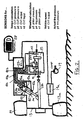
- the tractor 10 has a cab 11 and engine 12 which drives front and rear wheels 13 and 14 via a transmission diagrammatically shown at 15.
- the engine powers other components of the tractor such as an engine cooling fan 17, hydraulic pumps 18, air compressors 19 and an electrical generator 20.
- Front wheels 13 are mounted on a front axle shown diagrammatically at 21 and rear wheels 14 on a rear axle shown diagrammatically at 22.
- Rear implement attachment lower links 23 are attached to a back axle housing 24 by sensing pins 25.
- Front weights W1 are mounted on a weight support 26 attached to the front of the tractor chassis and beneath the tractor the moveable weight W2 is provided which can be moved in the fore and aft direction as indicated by arrow X in Figure 1 to adjust the weight distribution on the axles 21 and 22.
- An example of a suitable form of moveable weight W2 is disclosed in the Applicant's co-pending patent application No. 1017368.0 which is also shown in Figure 4 .
- a tractor control system mounted within the cab 11 is a tractor control system in accordance with the present invention which includes a processing unit 27 and a display terminal 28 which also acts as an input device for the control system.
- the tractor is provided with various sensors which feed their sensors signals to the processing unit 27.
- the output of the sensing pins 25 (which is indicative of the pull force being applied to any coupled implement or trailer) is fed via line 29 to processing unit 27.
- the ground speed V of the tractor is sensed by a radar unit 30 which feeds is speed signal via line 31 to processing unit 27.
- the position of the tractor is fed from GPS unit 32 via line 33 to control unit 27.
- the information received from GPS unit 32 may be alternatively used to determine ground speed V of the tractor which may be more precise than using radar unit 30.
- a fuel consumption sensor 34 is connected via line 35 to processing unit 27 and detects the amount of fuel being supplied from fuel tank 36 to engine 12.
- Engine 12 is controlled by an electronic unit 12a using performance maps indicated diagrammatically at 12b. Electronic unit 12a may alternatively deliver fuel consumption value based on engine parameters.
- Rear axle 22 is rigid and strain gauge sensors 37 are attached to each side of the back axle cast housing 24 to measure deflections of the back axle housing which are indicative of the load being supported by the rear wheels 14.
- the output of wheel load sensors 37 is fed via lines 38 to processing unit 27.
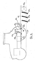
- Front axle 21 includes fluid pressure controlled suspension units 39 and 40 provided one on each side of the tractor and diagrammatically shown in Figure 2 .
- Each front wheel 13 has vertically moveable drive shaft 13b which is connected with transmission 15. This drive shaft 13b is supported by the associated suspension unit 39, 40 which is of the double acting type with chambers 41 and 42 provided on opposite sides of a moveable piston 43.
- the pressure in chambers 41 and 42 is sensed by pressure sensors 41 a and 42a and the position of piston 43 is sensed by position sensor 43a. These sensors communicate their outputs to control unit 27 via lines 41b, 42b and 43b respectively.
- the wheel loads determined from sensors 37, 41 a, 42a, and 43a may be verified by measuring the load applied on rear implement attachment lower links 23.
- the vertical implement load may be measured using the pressure in hydraulic hitch cylinders (not shown in Figure 1 ) which raise the draft links 23.
- the force applied to the tractor via the top link may be measured (either with another load pin or with pressure and angle sensors).
- the system may check, based on known values for the empty load of the tractor and the measured value for vertical load of the implement and wheel load whether a ballast weight is attached and the value of any added weight.
- Front wheels 13 are provided with a system for adjusting the pressure within front tyres 13a using compressor 19 and control valves 19a.
- a similar arrangement is provided for varying the pressure of the tyres 14a of the rear wheels 14.
- the tractor control system will advise the tractor operator as to the optimum weight of the tractor for the pull force being applied to the implement or trailer which the tractor is currently pulling and will also advise the operator as to the appropriate tyre pressure for the current wheel load and ground speed. If the tractor is fitted with a tyre pressure monitoring and inflation/deflation system then the control system can be arranged to automatically adjust the tyre pressure to the appropriate level.
- the same tyre pressure should be used in all tyres. Also for off road applications the lowest tyre pressure should be used which does not damage the tyres as this minimises rolling resistance and lowers contact pressure and increases pulling force due to the larger contact area with the ground.
- the tractor has pressure sensors 41a, 42a and position sensor 43a which enable the load supported by the wheels of the front axle 21 to be determined by the control unit and strain gauge sensors 37 associated with each side of the back axle housing 24 which enable the control unit to determine the load carried by the wheels of the rear axle 22.
- the total weight of the tractor can be determined during operation. If, for example, the load supported by the front wheels is 20kN. (2tons) and the load supported by the rear wheels is 60KN (6tons), the overall weight of the tractor is 80kN (8 tons).
- Pull force F being currently applied to the implement or trailer can be determined using the sensing pins 25 which connect the lower links 23 to the tractor chassis.
- the wheel or axle torque can be determined from the pressure in this hydraulic circuit and other parameters (e.g. intake volume of the hydraulic motor, ratio setpoint, pivot angle of the axial piston type hydraulic motor) .
- the wheel or axle torque, divided by the dynamic wheel radius is a measure for the wheel circumference force, consisting of rolling resistance force and pull thus giving a rough estimation of pull. (although problems can arise using this method of pull force determination as roll resistance must be considered).
- the main target is to reach a maximum for ETA so that the performance supplied by the wheels result in a maximum pull performance.
- Mobility index BN10 which does follow this assumption, must be seen as a soil condition which is not suitable for high pull performance operation, e.g. very wet, muddy ground.
- KAPPA KAPPA ⁇ ⁇ ⁇ ⁇ ⁇ ⁇ ⁇ ⁇ ⁇ ⁇ ⁇ ⁇ ⁇ ⁇ ⁇ ⁇ ⁇ ⁇ ⁇ ⁇ ⁇ ⁇ ⁇ ⁇ ⁇ ⁇ ⁇ ⁇ ⁇ ⁇ ⁇ ⁇ ⁇ ⁇ ⁇ ⁇ ⁇ ⁇ ⁇ ⁇ ⁇ ⁇ ⁇ ⁇ ⁇ ⁇ ⁇ ⁇ ⁇ ⁇ ⁇ ⁇ ⁇ ⁇ ⁇ ⁇ ⁇ ⁇ ⁇ ⁇ ⁇ ⁇ ⁇ ⁇ ⁇ ⁇ ⁇ ⁇ ⁇ ⁇ ⁇ ⁇ ⁇ ⁇ ⁇ ⁇ ⁇ ⁇ ⁇ ⁇ ⁇ ⁇ ⁇ ⁇ ⁇ ⁇ ⁇ ⁇ ⁇ ⁇ ⁇ ⁇ ⁇ ⁇ ⁇ ⁇ ⁇ ⁇ ⁇ ⁇ ⁇ ⁇ ⁇ ⁇ ⁇ ⁇ ⁇ ⁇ ⁇ ⁇ ⁇ ⁇ ⁇ ⁇ ⁇ ⁇ ⁇ ⁇ ⁇ ⁇ ⁇ ⁇ ⁇ ⁇
- Each tractor has an initial weight distribution which is defined by the design of the tractor and the relative weight and position of the tractor components.
- a standard tractor may have say a 35% of its weight on the front axle and 65% of its weight on the rear axle when no ballast weights or implement is attached.
- Tractor tyre manufacturers publish tables of the optimum tyre pressure to be used based on the ground speed of the tractor and the wheel load.
- Figure 5 shows tables for the front and rear tyres of a particular make of tyre of a particular size which are typical of the tyres fitted to many tractors.
- the processing unit 27 has the appropriate tyre pressure tables loaded for the tyres fitted to the tractor.
- this specified axle load ratio of 40/60 remains constant for a given tyre size and design for every speed and tyre pressure if a common pressure is used in all tyres as indicated above. So the additional weight to raise the overall weight of the tractor to 100kN must be added in a manner which achieves this 40/60 weight distribution.
- the system can calculate all the different options and displays alternatives to the operator depending on the features fitted to the tractor and the available weight options.
- the operator can add 20 kN exactly on the front axle and this will give a loading of 40 kN on the front axle and 60 kN on the back axle giving a total load equal to the optimum load of 100kN.
- the system may recognize and suggest the appropriate number of 200kg weights to be used. So instead of suggesting 1190 kg, which is technically not available, the system may then suggest 1200 kg as being the closest weight which the ballast weight system can achieve.
- adjusting the weight distribution between the axles may not be easy to achieve. If the tractor is provided with a weight 45 at least part of which 45a can be moved in a fore and aft sense (see-arrow S in Figure 4 ) relative to the tractor chassis, as described in the previously referred to patent application No. 1017368.0 , then the weight distribution between the axles can be adjusted in the field either manually by the operator or automatically under the control of the tractor control system by operation of a hydraulic cylinder (not shown) or an electric motor (also not shown) which moves the weight 45a on guide rails 46.
- a hydraulic cylinder not shown
- an electric motor also not shown
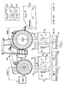
- a first hydraulic cylinder 47a is provided to move point 48 in a fore and aft sense.
- a second hydraulic cylinder 47b is provided to adjust heights level of point 48 (via rocker arm 47c and lift rod 47d).
- the implement may therefore be provided with a pivotable towing bar 49b driven by a hydraulic cylinder 49c.
- a lifting means may be assigned to the ground contact wheels 49d to adjust distance to ground.
- the hitch 47 is of a ball-type hitch. It is envisaged that other forms of hitch system, e.g. using rear implement attachment lower links 23 shown in Figure 1 , may be adapted to provide adjustability on one or both directions. Thereby, it is again possible to adjust the weight distribution either manually or automatically in the field.
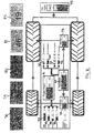
- FIG. 6 shows a tractor and implement combination provided with a implement weight transfer system in which a cylinder 50 acts between the tractor and implement 51 which can press down on the implement to reduce the weight carried by the rear axle or can pull up on the implement or transfer more of the implement weight onto the rear axle. Again with such an arrangement it is possible to adjust the weight distribution either manually or automatically in the field.
- the operator may attach more weight than will ultimately be needed before going to field. Once in the field the operator can then remove some of this weight in order to achieve the optimum overall weight and adjust the position of the weight to achieve the optimum weight distribution.
- Many tractors are fitted with special front weight arrangements which allow this weight to be added or remove using a front weight lifting unit.
- the driver can save the weight recommendations from the control system and add weight when returning to the farm (for taking fuel) or reloading or for use next year if he is going on the same field with the same implement.
- the tractor has a drive transmission which can vary the proportion of engine output torque which is directed to each axle, the torque is preferably proportioned so that each wheel operates at substantially the same level of slip relative to the contacting ground.
- the system measures torque at the wheel hub so the decision whether the tractor is driving 10 km/h (with high or low torque on the wheel hub) needed for the tyre table is taken by the system and not by the driver who can only guess about torque based on experience.
- the display terminal 18 of the system displays various operating parameters of the tractor such as tractor ground speed, fuel consumption, tractor position, current front and rear tyre pressures, wheel load and pull force.
- the terminal displays recommendations to the operator regarding tractor weight and tyre pressure.
- the system also warns the driver if, for example the wheel loading is too high for the current tyre pressure (if not automatically adjusting it). Or it may warn when tractor is overloaded or may tend to overturn due to an imbalance in the transverse or longitudinal wheel load distribution..
- Diesel has a specific energy content of about 35.6 MJ/1 ⁇ 10 kWh/1. So multiplying with the consumption per time delivers performance in kW.
- the map of fuel consumption against engine speed supplied by engine manufacturer can be used.
- the performance P on the wheel hub is depending on the output torque of the transmission MT (determined as described above depending on CVT parameters) and the wheel speed nT which can be sensed by having speed sensor in the respective wheels or by measuring the output speed of the transmission which is then transferred to wheel speed by including final drive ratios and efficiencies (if appropriate).
- the overall torque is distributed according ratios between the front and rear axle.
- each axle or wheel can be considered resulting in an overall sum.
- Pull force F being currently applied to the implement or trailer can be determined using the sensing pins 25 which connect the lower links 23 to the tractor chassis.
- the pull force can be determined from the pressure in this hydraulic circuit via transmission output torque.
- Pull force multiplied with current vehicle speed provides pull performance.
- the current vehicle speed is thereby measured by a Radar sensor or by using GPS data.
- Figures 7 and 8 show different layouts for the display of information to the tractor operator.
- FIG. 7 a depiction of the tractor is shown at 60 on which is displayed at 61 the front weight attached and at 62 the wheel weight attached.
- Display areas 63, 64 and 65 display the vehicle speed, acreage performance in hectares/hour and acreage fuel consumption in litres/ hectare.
- Display areas 66, 67, 68, 69 and 70 display the current pull force applied to the implement, front axle slip, front axle torque, rear axle slip and rear axle torque respectively.
- Display areas 71, 72 and 73 display engine efficiency, drive line efficiency and tractive efficiency.
- Display areas 74, 75, 76 and 77 display front tyre pressure, front wheel load, rear tyre pressure and rear wheel load respectively.
- an implement weight transfer system as described in Figure 6 is provided on the tractor, part of the weight of a coupled implement may be transferred to or from the associated tractor to adjust axle loading. Therefore, it may be advantageous to display the ratio of wheel load transferred by the implement.
- the display areas 75 or 77 showing front and rear wheel load may be split up in three values if the implement weight transfer system is activated representing:
- the display layout may change between different modes:
- the appearance of the display layout may be flexible. If the control system recognizes that an option shown in the maximum setting of the display is not available, e.g. the system to move the hitch point as described in Fig 3 is not being used, the display may blank or grey the respective area, so that the driver is not misguided.
- areas 78, 79, 80, 81 and 82 display the engine, driveline, traction, crank to hitch and tank to hitch efficiencies.
- Displays 83, 84, 85, 86 indicate the current power consumption in kW of the water pump, HVAC system, High Pressure pump and generator.
- displays 87, 88, 89 and 90 indicate the current power consumption in kW of the steering pump, air compressor, hydraulic pump and cooling fan.
- Display 91 shows the current power output of the engine in kW and displays 92 shows the proportion of the current engine output going to the transmission.
- Displays 93 and 94 show the power going to the rear and front wheels respectively whilst display 95 shows the current pulling power being applied to the implement or trailer.
- ETA Pull Force Performance Overall Wheel Hub Performance
- KAPP Pull Force Tractor weight
- the method includes the steps of:
- uphill and downhill driving may result in rogue values for KAPPA/ETA determination.
- An additional sensor e.g. an inclination sensor (which may be part of an Anti-Skid system) may provide respective information referring to uphill/downhill driving to eliminate these values.
- the system may contain other sensors to determine conditions where measured values represent rogue conditions not suitable for KAPPA determination. The respective values may then be sorted out according sensor information.
Landscapes
- Life Sciences & Earth Sciences (AREA)
- Engineering & Computer Science (AREA)
- Mechanical Engineering (AREA)
- Soil Sciences (AREA)
- Environmental Sciences (AREA)
- Physics & Mathematics (AREA)
- General Physics & Mathematics (AREA)
- Zoology (AREA)
- Chemical & Material Sciences (AREA)
- Combustion & Propulsion (AREA)
- Transportation (AREA)
- Lifting Devices For Agricultural Implements (AREA)
Description
- This invention relates to tractor control/display systems which record and display tractor performance parameters and may also control certain functions of the tractor in order to improve its performance. In particular, the invention relates to a tractor control/display system including a display means for displaying to a tractor operator tractor performance parameters and receiving operator's inputs, sensors to determine various operating conditions of the tractor, and a processing unit for receiving the sensor signals and operator's inputs and processing these signals and inputs to provide selected performance parameters for display on the display means.
- Whilst such systems are already known they tend to rely heavily on the operator to interpret the results of the data displayed and make the correct adjustment to the operating conditions of the tractor to improve its performance. An example of such a system is described in
US 2001/001844 A1 . - The term "performance" as used throughout this application should be interpreted broadly so that, for example, it is seen as equivalent to the term "power" in the sense that performance may be a parameter with the unit of, for example, Watts or Kilowatts but may also mean a performance related to a working process with units of, for example, hectare/per hour.
- It is an object of the present invention to provide a control/display system which helps the tractor operator to maximise the performance of the tractor.
- Thus according to the present invention there is provided a tractor control/display system as set forth in the opening paragraph, characterised in that the processing unit also provides a simulation mode in which the operator can enter proposed changes in operating conditions of the tractor and the processing means can indicate on the display means the effect of these proposed changes on selected tractor performance parameters.
- As will be appreciated, the provision of the simulation mode enables the operator to try various alternative changes to the operating conditions of the tractor to ascertain the best option before implement the change This speeds up the setting up of the tractor for efficient operation.
- The display means may advise the operator on changes which can be made to the operating conditions of the tractor to improve operating efficiency.
- Conveniently the display means differentiates between measured values of displayed parameters, advised values of the displayed parameters, values of the displayed parameters changed by the operator and simulated values of the displayed parameters.
- The system may differentiate between the different types of, displayed parameters by using different display pages and/or separate pop-up menus and/or different colours for the different types of displayed values.
- The processing unit can be set up to issue output signals to automatically change certain operating conditions of the tractor to improve operating efficiency.
- The processing unit may recognise when certain facilities or functions are not available on the tractor and advises the operator accordingly via the display means.
- Conveniently the display means indicates the current axle and/or wheel loading of the tractor.
- When the tractor has a rigid unsprung axle the wheel load may be measured by a strain gauge type sensor which measures the deflection of part of the rigid axle which supports a wheel.
- If the tractor has an axle suspended by fluid pressure the wheel load can be determined by measuring the fluid pressure which is suspending the axle and the position of the axle.
- For a tractor with two or more axles which carry wheels having pneumatic tyres sensors may be provided for determining the current pull force applied to an implement or trailer pulled by the tractor, the current wheel load and the current tractor ground speed, the processing unit determining and advising the tractor operator via the display means as to the optimum weight of the tractor using a predetermined relationship between pull force and tractor weight and also the required load on each axle to achieve a predetermined optimum axle load ratio.
- Such a system may also advise the operator via the display means as to the appropriate tyre pressure for the current wheel load and tractor ground speed using a look-up table.
- The look-up table may provide the lowest equal tyre pressure appropriate for the current wheel load, ground speed and tyre size fitted to the tractor to give minimum ground pressure to carry the load.
- Typically the optimum axle load ratio applied is a 40/60 front/rear axle load ratio.
- The predetermined ratio of pull force /tractor weight is typically 0.4.
- Alternatively the processing unit calculates a real time value for the current ratio of pull force/tractor weight.
- The real time value of the current ratio of pull force/tractor weight may be calculated by measuring a plurality of individual values of pull force over a sample period and calculating in the processing unit the respective rations therefrom, eliminating extreme and/or clearly incorrect or unrepresentative individual ratio values, averaging the ratio values in individual ratio zones and plotting these averaged zonal ratio values recorded in the sample period to generate a best fit curve for these plotted values, then selecting as the current real time value either the average ratio value for the ratio zone in which the tractor is operating for the longest time or the ratio on the curve with the highest value of tractive efficiency (pull force applied to implement or trailer/performance output at wheel hub).
- The pull force may be measured using sensing pins which attach the lower implement attachment links to the tractor.
- The display means may display the current pull force applied to the implement or trailer.
- If the tractor includes a transmission with a hydraulic circuit in which a hydraulic pump supplies pressure to a hydraulic motor, the pull force can be determined by sensing the pressure in the hydraulic circuit, whereby the pressure in the hydraulic circuit is a measure of the wheel or axle torque, the wheel or axle torque divided by the dynamic wheel radius being a measure of the wheel circumference force, consisting of rolling resistance force and pull force thus giving a rough estimation of pull force.
- In a system for a tractor in which the proportion of the weight of the implement or trailer which is supported by the tractor can be varied, the display means may indicate the weight of the implement or trailer supported by the tractor to assist the operator in varying the axle load distribution towards the required figure determined by the system.
- An above system may be provided in which a rear hitch allows the attachment point of the implement or trailer to be moved in a fore, aft and/or downwards and upwards sense relative to the tractor to change the axle load distribution towards the required figure determined by the system.
- The vertical load applied by the implement or trailer to the tractor may be measured using pressure sensors in hydraulic cylinders driving lower implement attachment links or top link.
- In a tractor provided with a weight which is moveable in a fore and aft sense relative to the tractor, the display means can indicate the change in axle load resulting from the movement of the weight to assist the operator in varying the axle load distribution towards the required figure determined by the system.
- In a tractor having driven front and rear axles and provided with a drive transmission which can vary the proportion of engine output torque which is directed to each axle, the display means can display the output torque delivered to each axle.
- The processing means may proportion the engine torque between the axles so that each wheel operates at substantially the same level of slip relative to the contacting ground, independent of external operating conditions (like ground topography, steering angle).
- The display means may display the wheel slip of each axle.
- The processing means may calculate and the display means may display engine efficiency which is equal to the engine output performance at the crank shaft / output provided by the fuel consumed.
- The processing means may calculate and the display means may display driveline efficiency which is equal to performance output at the wheel hub/ performance output at the crank shaft.
- The processing means may calculate and the display means may display tractive efficiency which is equal to the pull force applied to the implement or trailer/ performance output at the wheel hub.
- The processing means may calculate and the display means may display crank to hitch efficiency which is equal to the pull force applied to the implement or trailer/ performance output at the crank shaft.
- The processing means may calculate and the display means may display tank to hitch efficiency which is equal to the pull force applied to the implement or trailer/ output provided by the fuel consumed.
- The present invention will now be described with reference to the accompanying drawings in which:-
-
Figure 1 shows a diagrammatic view of a tractor showing the various sensors used by a control system in accordance with the present invention; -
Figure 2 show diagrammatically details of a suspended axle and CVT transmission and the associated sensors for the determination of wheel load and applied torque; -
Figure 3 shows diagrammatically how the point of attachment of an implement may be moved in the fore and aft and/or upwards and downwards direction relative to a tractor; -
Figure 4 shows diagrammatically how a weight may be moved in a fore and aft direction relative to a tractor to adjust axle loading: -
Figure 5 shows look-up tables used to establish the front and rear wheel tyre pressures dependent on wheel load and tractor ground speed; -
Figure 6 shows diagrammatically how the weight of a coupled implement may be transferred to or from the associated tractor to adjust axle loading; -
Figures 7 and8 show diagrammatically alternative forms of display layout which can be used in a control system in accordance with the present invention; -
Figure 9 shows a characteristic map of the relationship between the Tractive Efficiency (ETA) and the driving force coefficient or net traction ratio (KAPPA) related to different soil conditions represented the mobility index (BN), and -
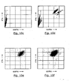
Figures 10a to 10g show the measurement and analysis of the driving force coefficient or net traction ratio (KAPPA) in real time. - Referring to the drawings, the
tractor 10 has acab 11 andengine 12 which drives front andrear wheels Figure 1 , the engine powers other components of the tractor such as anengine cooling fan 17,hydraulic pumps 18,air compressors 19 and anelectrical generator 20.Front wheels 13 are mounted on a front axle shown diagrammatically at 21 andrear wheels 14 on a rear axle shown diagrammatically at 22. Rear implement attachmentlower links 23 are attached to aback axle housing 24 by sensingpins 25. - Front weights W1 are mounted on a
weight support 26 attached to the front of the tractor chassis and beneath the tractor the moveable weight W2 is provided which can be moved in the fore and aft direction as indicated by arrow X inFigure 1 to adjust the weight distribution on theaxles 1017368.0 Figure 4 . - Mounted within the
cab 11 is a tractor control system in accordance with the present invention which includes aprocessing unit 27 and adisplay terminal 28 which also acts as an input device for the control system. - The tractor is provided with various sensors which feed their sensors signals to the
processing unit 27. For example, the output of the sensing pins 25 (which is indicative of the pull force being applied to any coupled implement or trailer) is fed vialine 29 toprocessing unit 27. The ground speed V of the tractor is sensed by aradar unit 30 which feeds is speed signal via line 31 toprocessing unit 27. The position of the tractor is fed fromGPS unit 32 vialine 33 to controlunit 27. The information received fromGPS unit 32 may be alternatively used to determine ground speed V of the tractor which may be more precise than usingradar unit 30. Afuel consumption sensor 34 is connected via line 35 toprocessing unit 27 and detects the amount of fuel being supplied fromfuel tank 36 toengine 12.Engine 12 is controlled by anelectronic unit 12a using performance maps indicated diagrammatically at 12b.Electronic unit 12a may alternatively deliver fuel consumption value based on engine parameters. -
Rear axle 22 is rigid and strain gauge sensors 37 are attached to each side of the back axle casthousing 24 to measure deflections of the back axle housing which are indicative of the load being supported by therear wheels 14. The output of wheel load sensors 37 is fed vialines 38 toprocessing unit 27. -
Front axle 21 includes fluid pressure controlledsuspension units 39 and 40 provided one on each side of the tractor and diagrammatically shown inFigure 2 . Eachfront wheel 13 has vertically moveable drive shaft 13b which is connected withtransmission 15. This drive shaft 13b is supported by the associatedsuspension unit 39, 40 which is of the double acting type withchambers 41 and 42 provided on opposite sides of a moveable piston 43. By controlling the pressure levels inchamber 41 and 42 and the position of piston 43 the level of damping and ride height of the front wheels is determined. When the tractor has a suspendedfront axle 21, as shown inFigure 2 , the pressure inchambers 41 and 42 is sensed bypressure sensors position sensor 43a. These sensors communicate their outputs to controlunit 27 vialines 41b, 42b and 43b respectively. - The wheel loads determined from
sensors lower links 23. - The vertical implement load may be measured using the pressure in hydraulic hitch cylinders (not shown in
Figure 1 ) which raise the draft links 23. For a tractor fitted with a three point coupling, the force applied to the tractor via the top link (also not shown inFigure 1 ) may be measured (either with another load pin or with pressure and angle sensors). - Since the wheel load of a tractor results from:
- Empty load of the tractor
- + Addditional ballast weight
- + vertical load of the implement,
- = Overall wheel load.
- So the system may check, based on known values for the empty load of the tractor and the measured value for vertical load of the implement and wheel load whether a ballast weight is attached and the value of any added weight.
-
Front wheels 13 are provided with a system for adjusting the pressure withinfront tyres 13a using compressor 19 andcontrol valves 19a. A similar arrangement is provided for varying the pressure of thetyres 14a of therear wheels 14. In accordance with the present invention, the tractor control system will advise the tractor operator as to the optimum weight of the tractor for the pull force being applied to the implement or trailer which the tractor is currently pulling and will also advise the operator as to the appropriate tyre pressure for the current wheel load and ground speed. If the tractor is fitted with a tyre pressure monitoring and inflation/deflation system then the control system can be arranged to automatically adjust the tyre pressure to the appropriate level. - For lowest overall sinking of the tyres into the soil and for minimum compaction the same tyre pressure according appropriate wheel load distribution should be used in all tyres. Also for off road applications the lowest tyre pressure should be used which does not damage the tyres as this minimises rolling resistance and lowers contact pressure and increases pulling force due to the larger contact area with the ground.
- As described above, the tractor has
pressure sensors position sensor 43a which enable the load supported by the wheels of thefront axle 21 to be determined by the control unit and strain gauge sensors 37 associated with each side of theback axle housing 24 which enable the control unit to determine the load carried by the wheels of therear axle 22. Thus the total weight of the tractor can be determined during operation. If, for example, the load supported by the front wheels is 20kN. (2tons) and the load supported by the rear wheels is 60KN (6tons), the overall weight of the tractor is 80kN (8 tons). - Pull force F being currently applied to the implement or trailer can be determined using the sensing pins 25 which connect the
lower links 23 to the tractor chassis. Alternatively, if a CVT transmission is used with a hydraulic pump and motor circuit, the wheel or axle torque can be determined from the pressure in this hydraulic circuit and other parameters (e.g. intake volume of the hydraulic motor, ratio setpoint, pivot angle of the axial piston type hydraulic motor) . The wheel or axle torque, divided by the dynamic wheel radius is a measure for the wheel circumference force, consisting of rolling resistance force and pull thus giving a rough estimation of pull. (although problems can arise using this method of pull force determination as roll resistance must be considered). - If the current pull force F is say 40kN (4tons), then, using the generally accepted relationship of Pull Force/ Tractor weight, which is also known as driving force coefficient or net traction ratio KAPPA, of 0.4 this gives an optimum tractor weight of 100kN (10tons). This relation of 0.4 is chosen based the characteristic maps empirically determined by Zoz, Brixius and others shown in
Fig. 9 . The characteristic map shows the relationship between the Tractive Efficiency ETA and the driving force coefficient KAPPA related to different soil conditions shown in lines BN10, BN15 etc. BN thereby represents the mobility index which is empirically determined for different soil conditions and tyre sizes. The TractiveEfficiency ETA is determined by the equation:
- As clearly seen form the above shown equation, the main target is to reach a maximum for ETA so that the performance supplied by the wheels result in a maximum pull performance.
- As shown in
Fig 9 different soil conditions are represented by different mobility indexes BN. It will be noted that formobility indexes BN 15,BN 25,BN 40 and Concrete the maximum value of ETA is achieved at a value of KAPPA around 0.4. Mobility index BN10, which does follow this assumption, must be seen as a soil condition which is not suitable for high pull performance operation, e.g. very wet, muddy ground. - The above method of deriving KAPPA gives a sufficiently accurate value of KAPPA for most tractor applications. Other characteristic maps (e.g. for further regions and soil conditions), may result in other values for KAPPA.
- Thus in the example quoted the operator needs to add 20kN (2tons) ballast weight to reach the optimum tractor weight. The question is now where should this weight be added to achieve the optimum axle load ratio and what is the optimum axle load ratio.
- Each tractor has an initial weight distribution which is defined by the design of the tractor and the relative weight and position of the tractor components. A standard tractor may have say a 35% of its weight on the front axle and 65% of its weight on the rear axle when no ballast weights or implement is attached.
- Tractor tyre manufacturers publish tables of the optimum tyre pressure to be used based on the ground speed of the tractor and the wheel load.
Figure 5 shows tables for the front and rear tyres of a particular make of tyre of a particular size which are typical of the tyres fitted to many tractors. Theprocessing unit 27 has the appropriate tyre pressure tables loaded for the tyres fitted to the tractor. - If the tractor is currently operating at a ground speed of say 10km/h in a low torque (LT) operation, then looking along the last but one line of the tables of
Figure 5 it can be seen that if a tyre pressure of 1.0 bar is selected this would give a total load capacity of 3645 for the front axle and 5590 for the rear axle. This gives a total load capacity of approximately 10kN which is the optimum lad capacity required for the current task. - This gives a front axle load percentage of 3645/9235 or 39.5% and a rear axle load percentage of 5590/9235 or 60.5% which rounded up is an axle load ratio front/rear of 40/60.
- If one calculates the axle load ratio at 50 km/h using the table in
Figure 5 this gives a front axle load of 3685 and a rear load of 5650 at a common pressure of 1.4 bar. This again gives a ratio of 39.5/60.5, rounded up to 40/60. - So, this specified axle load ratio of 40/60 remains constant for a given tyre size and design for every speed and tyre pressure if a common pressure is used in all tyres as indicated above. So the additional weight to raise the overall weight of the tractor to 100kN must be added in a manner which achieves this 40/60 weight distribution.
- To reach this optimum weight distribution we have a number of possibilities:
- adding (or removing) ballast at one specific position;
- adding and/or removing ballast at more then one position (i.e. rear and front);
- moving the point at which the implement or trailer is coupled to the tractor in a fore and aft and/or upwards and downwards sense (particularly when the implement is coupled to the tractor in front of the rear axle and applies additional downward forces to the tractor|);
- combinations of the above possibilities;
- moving weight on the tractor in a fore and aft sense as mentioned in the Applicant's co-pending application No.
1017368.0 - providing a weight transfer system such as a hydraulic cylinder acting between the tractor and implement which can press down on the implement to reduce the weight carried by the rear axle or can pull up on the implement or transfer more of the implement weight onto the rear axle.
- moving weight on the tractor in a fore and aft sense as mentioned in the Applicant's co-pending application No.
- The system can calculate all the different options and displays alternatives to the operator depending on the features fitted to the tractor and the available weight options.
- For example, assuming that the operator has the ability to add front ballast on top of the front axle and remembering that the tractor currently has a 20 kN loading on the front axle and a 60 kN load on the back axle, the operator can add 20 kN exactly on the front axle and this will give a loading of 40 kN on the front axle and 60 kN on the back axle giving a total load equal to the optimum load of 100kN.
- Alternatively, if, for example, the vehicle manufacturer offers a front ballast weight system with a total weight of say 1800 kg, separated in nine detachable ballast parts of 200 kg., the system may recognize and suggest the appropriate number of 200kg weights to be used. So instead of suggesting 1190 kg, which is technically not available, the system may then suggest 1200 kg as being the closest weight which the ballast weight system can achieve.
- As will be appreciated, adjusting the weight distribution between the axles may not be easy to achieve. If the tractor is provided with a
weight 45 at least part of which 45a can be moved in a fore and aft sense (see-arrow S inFigure 4 ) relative to the tractor chassis, as described in the previously referred to patent application No.1017368.0 weight 45a on guide rails 46. - If the tractor is fitted with a
rear hitch 47, as shown inFigure 3 , in which thepoint 48 at which the implement ortrailer 49 is coupled to thetractor 10 can be moved in a fore and aft and/or upwards and downwards sense. A firsthydraulic cylinder 47a is provided to movepoint 48 in a fore and aft sense. A second hydraulic cylinder 47b is provided to adjust heights level of point 48 (viarocker arm 47c and lift rod 47d). - As a consequence changing the height of
point 48 would result in an unmeant adjustment of the working dept of theground engaging means 49a of the implement. The implement may therefore be provided with a pivotable towing bar 49b driven by ahydraulic cylinder 49c. Alternatively, a lifting means may be assigned to theground contact wheels 49d to adjust distance to ground. In the shown embodiment, thehitch 47 is of a ball-type hitch. It is envisaged that other forms of hitch system, e.g. using rear implement attachmentlower links 23 shown inFigure 1 , may be adapted to provide adjustability on one or both directions. Thereby, it is again possible to adjust the weight distribution either manually or automatically in the field. -
Figure 6 shows a tractor and implement combination provided with a implement weight transfer system in which acylinder 50 acts between the tractor and implement 51 which can press down on the implement to reduce the weight carried by the rear axle or can pull up on the implement or transfer more of the implement weight onto the rear axle. Again with such an arrangement it is possible to adjust the weight distribution either manually or automatically in the field. - If the tractor is not provided with the above arrangements then the operator may attach more weight than will ultimately be needed before going to field. Once in the field the operator can then remove some of this weight in order to achieve the optimum overall weight and adjust the position of the weight to achieve the optimum weight distribution. Many tractors are fitted with special front weight arrangements which allow this weight to be added or remove using a front weight lifting unit.
- Also, the driver can save the weight recommendations from the control system and add weight when returning to the farm (for taking fuel) or reloading or for use next year if he is going on the same field with the same implement.
- If the tractor has a drive transmission which can vary the proportion of engine output torque which is directed to each axle, the torque is preferably proportioned so that each wheel operates at substantially the same level of slip relative to the contacting ground.
- In addition, the system measures torque at the wheel hub so the decision whether the tractor is driving 10 km/h (with high or low torque on the wheel hub) needed for the tyre table is taken by the system and not by the driver who can only guess about torque based on experience.
- The
display terminal 18 of the system displays various operating parameters of the tractor such as tractor ground speed, fuel consumption, tractor position, current front and rear tyre pressures, wheel load and pull force. - Additionally, as discussed above, the terminal displays recommendations to the operator regarding tractor weight and tyre pressure. The system also warns the driver if, for example the wheel loading is too high for the current tyre pressure (if not automatically adjusting it). Or it may warn when tractor is overloaded or may tend to overturn due to an imbalance in the transverse or longitudinal wheel load distribution..
- In addition, the terminal display also shows Efficiency parameters such as :


- The various values required to determine the above efficiency parameters are determined as follows:-
- is determined from the characteristic map of engine power output plotted against engine speed .which are provided by the engine manufacturer with assumptions made as to power which should be subtracted which is supplied to secondary drives like cooling fan or pumps for oil and water.
- is determined by multiplying the fuel consumed with the chemical energy content of the fuel. Diesel has a specific energy content of about 35.6 MJ/1 ~ 10 kWh/1. So multiplying with the consumption per time delivers performance in kW. Alternatively the map of fuel consumption against engine speed supplied by engine manufacturer can be used.
- is calculated by:

- Whereby the performance P on the wheel hub is depending on the output torque of the transmission MT (determined as described above depending on CVT parameters) and the wheel speed nT which can be sensed by having speed sensor in the respective wheels or by measuring the output speed of the transmission which is then transferred to wheel speed by including final drive ratios and efficiencies (if appropriate). In case of a vehicle equipped with fixed torque distribution to each axle, like in current standard tractors, the overall torque is distributed according ratios between the front and rear axle. Alternatively, if the torque can be distributed independently, each axle or wheel can be considered resulting in an overall sum.
- Pull force F being currently applied to the implement or trailer can be determined using the sensing pins 25 which connect the
lower links 23 to the tractor chassis. Alternatively, if a CVT transmission is used with a hydraulic pump and motor circuit, the pull force can be determined from the pressure in this hydraulic circuit via transmission output torque., - Pull force multiplied with current vehicle speed provides pull performance. The current vehicle speed is thereby measured by a Radar sensor or by using GPS data.
- These efficiency values may be displayed as absolute values. However, since typically 81 % of the input provided by fuel is lost on its way through the tractor it may be preferable to give each parameter a maximum efficiency value and then display the parameter using a scale ending up with 100%.
-
Figures 7 and8 show different layouts for the display of information to the tractor operator. - In
Figure 7 a depiction of the tractor is shown at 60 on which is displayed at 61 the front weight attached and at 62 the wheel weight attached.Display areas 63, 64 and 65 display the vehicle speed, acreage performance in hectares/hour and acreage fuel consumption in litres/ hectare.Display areas Display areas Display areas - If an implement weight transfer system as described in
Figure 6 is provided on the tractor, part of the weight of a coupled implement may be transferred to or from the associated tractor to adjust axle loading. Therefore, it may be advantageous to display the ratio of wheel load transferred by the implement. E.g. thedisplay areas - 1) the wheel load portion received resulting from the weight of the tractor and any ballast weight added but excluding any implement weight transfer;
- 2) the wheel load portion resulting from the transfer of part of the weight of the implement on to the tractor, and
- 3) The overall sum of 1) and 2)
- With such a three part display the operator can see the different influencing parameters in detail.
- The display layout may change between different modes:
- A) A fist information mode which only shows the information about the parameters. This mode may include warning e.g. if the acceptable wheel load is exceeded or the set point of the tyre pressure adjusted by the driver (if not automatically) does not meet the requirements according size and wheel load defined by look-up tables as described in
Fig. 5 . - B) A second mode may give the operator the possibility to change settings manually, e.g to enter ballast weight added.
- C) A third mode, which may be included in the second mode, which may give advice to the operator which values must be changed (e.g. ballast weight) to improve efficiency.
- D) A fourth mode in accordance with the present invention in which the driver's input is processed and the results of the real-time simulation are shown. In this simulation mode the operator can input proposed changes and use the simulation facility to check the effect of the planned changes before physically trying them on the tractor. This is an important step forward in the art which greatly improves the usefulness of the display/control system.
- These modes may be provided by pop-up menus, extra pages or by using different colours for measured values, advised values, values changed by operator and simulation results.
- In addition, the appearance of the display layout may be flexible. If the control system recognizes that an option shown in the maximum setting of the display is not available, e.g. the system to move the hitch point as described in
Fig 3 is not being used, the display may blank or grey the respective area, so that the driver is not misguided. - In the alternative display arrangement of
Figure 8 ,areas Displays 83, 84, 85, 86 indicate the current power consumption in kW of the water pump, HVAC system, High Pressure pump and generator. Similarly displays 87, 88, 89 and 90 indicate the current power consumption in kW of the steering pump, air compressor, hydraulic pump and cooling fan. Display 91 shows the current power output of the engine in kW and displays 92 shows the proportion of the current engine output going to the transmission.Displays 93 and 94 show the power going to the rear and front wheels respectively whilstdisplay 95 shows the current pulling power being applied to the implement or trailer. - In the embodiment described above, a constant value of 0.4 for the quotient of Pull Force and Tractor Weight, which is known as the driving force coefficient KAPPA, is used. However a more accurate control can be obtained if the actual real time value of KAPPA is used. A method of determine the real time value of KAPPA in dependency of / in relation to the TractiveEfficiency ETA is described below with reference to with
Figures 10a to 10g . - In general, the parameters which need to be measured in real time to determine ETA and KAPPA are:


- The method includes the steps of:
- A) Driving the tractor over the ground and measuring the parameter values to determine ETA and KAPPA. These values are plotted on a scatter-plot representing ETA in dependency of KAPPA. The scatter-plot is a consequence of dynamic oscillations, e.g. caused by non homogeneous soil or uphill or downhill driving. In
figure 10a the graph is limited to a maximum value of KAPPA=0.5 which is result of the soil condition during the particular measurement sequence. For other soil conditions, the range of KAPPA may be different:- Tests in the field have shown that a measurement run of about 1 minute may be sufficient.
- As best seen in
Fig 10a , the tractive efficiency varies inbetween -0.5 (-50%) and 2.0 (200%) which is not possible in a physical sense.
- B) Therefore, the next step is to purge the scatter-plot which is cleaned up by removing values outside the range ETA= 0 to 1.0. This results in the graph shown in
Fig. 10b . - C) A Further step provides a second level of purging the graph.
Fig 10c to 10e shows different sets of values extracted fromFig. 10b which are eliminated thus:-
Fig. 10c shows those values where the pull force was very minor. For example, values received when the implement was lifted (e.g. during headland travel) are eliminated. -
Fig 10d shows values which are eliminated due to the fact that these values were received during high acceleration (both, negative and positive). We only want to use KAPPA values which represent the pull force used when moving at a substantially constant speed hence the values high acceleration values ofFigure 10d are eliminated. -
Fig. 10e show further values to be eliminated. If the value for the tractive efficiency varies very much within a short period of time, this indicates failures during measurement and can be determined by the derivation of ETA. Those related values are also deleted.
-
- As shown in
Fig. 10f , a scatter-plot remains which is purged with regard to extreme variations. - D) In the next step, the scale for KAPPA is split up into small intervals of say 0.01257. All the measured values for ETA in a particular interval are then averaged and the average value for each time interval is plotted resulting in the line graph G shown in
Fig. 10g . This graph G represents a smoothing function achieved by the above averaging technique (in this case determined by adding a fourth degree polynomial based on the method of the minimum error square). Furthermore, the main working point WP is identified by determining the interval of KAPPA in which the tractor operates for the longest time. - As seen in
Figure 10g the current working point WP (ETA=0.85; KAPPA= 0.34) is below the maximum ETA value (ETA approx. 0.90 and KAPPA=0,39). - There are two alternative methods to define the target for KAPPA:
- Based on a smoothing function:
- The working point is moved on the determined graph G to the point of maximum ETAMAX. This, for example in the results shown in
Figure 10g , corresponds to KAPPA value of 0.39 may result in failure caused by the smoothing function. But as e.g. ballast weight may only be available in fixed steps, this will be sufficient in practice.
- The working point is moved on the determined graph G to the point of maximum ETAMAX. This, for example in the results shown in
- Based on characteristic maps for BN:
- The control system contains various characteristic maps similar to the one shown in
Figure 9 which may represent different soil conditions. These characteristic maps may be taken from literature or specific measurements on the respective field area. With the help of main working point WP the most suitable curve representing the mobility index BN can be identified. Similar to the method mentioned above, the working point is then moved towards maximum ETA and delivers the value for KAPPA.
- The control system contains various characteristic maps similar to the one shown in
- As described in Step A, uphill and downhill driving may result in rogue values for KAPPA/ETA determination. An additional sensor, e.g. an inclination sensor (which may be part of an Anti-Skid system) may provide respective information referring to uphill/downhill driving to eliminate these values. The system may contain other sensors to determine conditions where measured values represent rogue conditions not suitable for KAPPA determination. The respective values may then be sorted out according sensor information.
- The described determination of ETA and KAPPA during operation offers a real-time capable procedure to adapt parameters of the vehicle according soil condition. In the shown embodiment the focus was on weight optimization. It is envisaged that the methods offers additional possibilities:
- The soil conditions determined with the procedure may be used to generate soil condition maps which are later on used for precision farming
- On the tractor, information about soil conditions may be used to adjust soil work, e.g. to adjust the working depth of a plough according current soil condition.
- Additionally, knowing soil moisture may be used to optimise irrigation.
- As discussed above, to reduce soil compaction and improve tractive efficiency, the lowest possible tyre pressure should be chosen. Look-up tables provided by tyre manufactures are based on a usage on hard ground like concrete or asphalt. The values given ensure that, on hard ground, the tyre deformation is limited to a level which avoids damage. The tyre pressure values may be much lower on soft ground as part of the tyre deformation is transferred into soil deformation. The system described above may be used to determine softer soil condition and thereby define lower tyre pressures than given in current look-up tables. The set-up for soft ground may be defined in cooperation with a tyre manufacturer and enable a even more reduced tyre pressure without damaging the tyre.
- The present invention is defined by the following claims.
Claims (32)
- A tractor control/display system including a display means (28) for displaying to a tractor operator tractor performance parameters and receiving operator's inputs, sensors (30, 34, 37) to determine various operating conditions of the tractor (10), and a processing unit (27) for receiving the sensor signals and operator's inputs and processing these signals and inputs to provide selected performance parameters for display on the display means (28), characterised in that the processing unit (27) also provides a simulation mode in which the operator can enter proposed changes in operating conditions of the tractor and the processing unit (27) can indicate on the display means (28) the effect of these proposed changes on selected tractor performance parameters.
- A system according to claim 1 in which the display means (28) advises the operator on changes which can be made to the operating conditions of the tractor (10) to improve operating efficiency.
- A system according to claim 2 in which the display means (28) differentiates between measured values of displayed parameters, advised values of the displayed parameters, values of the displayed parameters changed by the operator and simulated values of the displayed parameters.
- A system according to claim 3 in which the system differentiates between the different types of displayed parameters by using different display pages and/or separate pop-up menus and/or different colours for the different types of displayed values.
- A system according to any one of claims 1 to 4 in which the processing unit (27) can be set up to issue output signals to automatically change certain operating conditions of the tractor (10) to improve operating efficiency.
- A system according to any one of claims 1 to 5 in which the processing unit (27) recognises when certain facilities or functions are not available on the tractor and advises the operator accordingly via the display means (28).
- A system according to any one of claims 1 to 6 in which the display means (28) indicates the current axle and/or wheel loading of the tractor (10).
- A system according to any one of claims 1 to 7 for a tractor with a rigid unsprung axle (22) in which the wheel load is measured by a strain gauge type sensor (37) which measures the deflection of part of the rigid axle which supports a wheels (14).
- A system according to any one of claims 1 to 7 for a tractor having an axle (21) suspended by fluid pressure in which the wheel load is determined by measuring the fluid pressure (41a, 42a) which is suspending the axle and the position of the axle.
- A system according to any one of claims 1 to 9 for a tractor (10) with two or more axles (21, 22) which carry wheels (13, 14) having pneumatic tyres in which sensors are provided for determining the current pull force (F) applied to an implement or trailer (49) pulled by the tractor, the current wheel load and the current tractor ground speed (V), the processing unit (27) determining and advising the tractor operator via the display means (28) as to the optimum weight of the tractor using a predetermined relationship between pull force (F) and tractor weight and also the required load on each axle (21, 22) to achieve a predetermined optimum axle load ratio.
- A system according to claim 10 in which the system also advises the operator via the display means (28) as to the appropriate tyre pressure for the current wheel load and tractor ground speed using a look-up table.
- A system according to claim 1 in which the look-up table provides the lowest equal tyre pressure appropriate for the current wheel load, ground speed and tyre size fitted to the tractor to give minimum ground pressure to carry the load.
- A system according to any one of claims 10 to 12 in which the optimum axle load ratio applied is a 40/60 front/rear axle load ratio.
- A system, according to any one of claims 10 to 13 in which the predetermined ratio of pull force /tractor weight is 0.4.
- A system according to any one of claims 10 to 13 in which the processing unit (27) calculates a real time value for the current ratio (KAPPA) of pull force/tractor weight.
- A system according to claim 15 in which the real time value of.the current ratio (KAPPA) of pull force/tractor weight is calculated by measuring a plurality of individual values of pull force over a sample period and calculating in the processing unit (27) the respective ratios therefrom, eliminating extreme and/or clearly incorrect or unrepresentative individual ratio values, averaging the ratio values in individual ratio zones and plotting these averaged zonal ratio values recorded in the sample period to generate a best fit curve for these plotted values, then selecting as the current real time value either the average ratio value for the ratio zone in which the tractor (10) is operating for the longest time or the ratio on the curve with the highest value of tractive efficiency (pull force applied to implement or trailer/performance output at wheel hub).
- A system according to claim 15 or 16 in which the real time value of the current ratio of pull force /tractor weight is displayed on the display means (28).
- A system according to any one of claims 10 to 17 in which pull force is measured using sensing pins (25) which attach the lower implement attachment links (23) to the tractor (10).
- A system according to claim 18 in which the display means (28) displays the current pull force applied to the implement or trailer.
- A system according to any one of claims 10 to 19 for a tractor (10) which includes a transmission (15) with a hydraulic circuit in which a hydraulic pump supplies pressure to a hydraulic motor, the pull force being determined by sensing the pressure in the hydraulic circuit, whereby the pressure in the hydraulic circuit is a measure of the wheel or axle torque, the wheel or axle torque divided by the dynamic wheel radius being a measure of the wheel circumference force, consisting of rolling resistance force and pull force thus giving a rough estimation of pull force.
- A system according to any one of claims 10 to 20 in which the proportion of the weight of the implement or trailer. (49) which is supported by the tractor can be varied, the display means (28) indicating the weight of the implement or trailer supported by the tractor to assist the operator in varying the axle load distribution towards the required figure determined by the system.
- A system according to claim 21. in which a rear hitch (47) which allows the attachment point (48) of the implement or trailer to be moved in a fore, aft and/or downwards and upwards sense relative to the tractor (10) to change the axle load distribution towards the required figure determined by the system.
- A system according to claim 21 or 22 in which the vertical load applied by the implement or trailer (49) to the tractor (10) is measured using pressure sensors in hydraulic cylinders driving lower implement attachment links or top link.
- A system according to any one of claims 10 to 23 for a tractor provided with a weight (45a) which is moveable in a fore and aft sense relative to the tractor (10), the display means (28) indicating the change in axle load resulting from the movement of the weight to assist the operator in varying the axle load distribution towards the required figure determined by the system.
- A system according to any one of claims 1 to 24 for a tractor having driven front (21) and rear (22) axles and provided with a drive transmission (15) which can vary the proportion of engine output torque which is directed to each axle, the display means (28) displaying the output torque delivered to each axle.
- A system according to claim 25 in which the processing unit (27) proportions the engine torque between the axles (21, 22) so that each wheel operates at substantially the same level of slip relative to the contacting ground.
- A system according to claim 26 in which the display means (28) displays the wheel slip of each axle.
- A system according to any one of claims 1 to 27 in which the processing unit (27) calculates and the display means (28) displays engine efficiency which is equal to the engine output performance at the crank shaft / output provided by the fuel consumed.
- A system according to any one of claims I to 28 in which the processing unit (27) calculates and the display means (28) displays driveline efficiency which is equal to performance output at the wheel hub/ performance output at the crank shaft.
- A system according to any one of claims 1 to 29 in which the processing unit (27) calculates and the display means (28) displays tractive efficiency which is equal to the pull force applied to the implement or trailer/ performance output at the wheel hub.
- A system according to any one of claims 1 to 30 in which the processing unit (27) calculates and the display means (28) displays crank to hitch efficiency which is equal to the pull force applied to the implement or trailer/ performance output at the crank shaft.
- A system according to any one of claims 1 to 31 in which the processing unit (27) calculates and the display means (28) displays tank to hitch efficiency which is equal to the pull force applied to the implement or trailer/ output provided by the fuel consumed.
Applications Claiming Priority (2)
| Application Number | Priority Date | Filing Date | Title |
|---|---|---|---|
| GBGB1112569.7A GB201112569D0 (en) | 2011-07-22 | 2011-07-22 | Tractor control/display systems |
| PCT/EP2012/062356 WO2013013915A1 (en) | 2011-07-22 | 2012-06-26 | Tractor control/display systems |
Publications (2)
| Publication Number | Publication Date |
|---|---|
| EP2734026A1 EP2734026A1 (en) | 2014-05-28 |
| EP2734026B1 true EP2734026B1 (en) | 2015-04-01 |
Family
ID=44586966
Family Applications (1)
| Application Number | Title | Priority Date | Filing Date |
|---|---|---|---|
| EP12730926.8A Active EP2734026B1 (en) | 2011-07-22 | 2012-06-26 | Tractor control/display systems |
Country Status (4)
| Country | Link |
|---|---|
| US (1) | US9095089B2 (en) |
| EP (1) | EP2734026B1 (en) |
| GB (1) | GB201112569D0 (en) |
| WO (1) | WO2013013915A1 (en) |
Cited By (1)
| Publication number | Priority date | Publication date | Assignee | Title |
|---|---|---|---|---|
| US10676141B2 (en) | 2017-04-05 | 2020-06-09 | Deere & Company | Method of providing a ballasting proposal |
Families Citing this family (29)
| Publication number | Priority date | Publication date | Assignee | Title |
|---|---|---|---|---|
| GB201112568D0 (en) * | 2011-07-22 | 2011-08-31 | Agco Int Gmbh | Tractor control system |
| GB201112569D0 (en) * | 2011-07-22 | 2011-08-31 | Agco Int Gmbh | Tractor control/display systems |
| WO2013112929A2 (en) | 2012-01-25 | 2013-08-01 | Precision Planting Llc | Agricultural toolbar apparatus, systems, and methods |
| US9686902B2 (en) * | 2012-12-18 | 2017-06-27 | Cnh Industrial America Llc | System and method for improving performance of an agricultural vehicle or implement |
| USD732576S1 (en) * | 2013-03-29 | 2015-06-23 | Deere & Company | Display screen or portion thereof with icon |
| USD738386S1 (en) * | 2013-03-29 | 2015-09-08 | Deere & Company | Display screen with an animated graphical user interface |
| RU2560210C2 (en) * | 2013-10-24 | 2015-08-20 | Общество с ограниченной ответственностью "Исследования и разработки АГРО" | Method of increasing machine-tractor plant efficiency |
| UA120259C2 (en) * | 2013-11-08 | 2019-11-11 | Пресіжн Плентінг Елелсі | Implement weight management systems, methods, and apparatus |
| GB201322746D0 (en) * | 2013-12-20 | 2014-02-05 | Agco Int Gmbh | Agricultural implement connection control |
| GB201322859D0 (en) * | 2013-12-23 | 2014-02-12 | Agco Int Gmbh | Vehicle control system |
| US20160016470A1 (en) * | 2014-03-25 | 2016-01-21 | Agco International Gmbh | Tractor control/display systems |
| US20160039480A1 (en) * | 2014-08-05 | 2016-02-11 | Agco International Gmbh | Tractor control system |
| US10113929B2 (en) | 2014-08-21 | 2018-10-30 | Caterpillar Paving Products Inc. | Use of wheel slip to help identify soft spots |
| GB201416989D0 (en) | 2014-09-26 | 2014-11-12 | Agco Int Gmbh | Vehicle ballasting assistance |
| GB201416990D0 (en) * | 2014-09-26 | 2014-11-12 | Agco Int Gmbh | Determining optimal ballasting |
| EP3100601B1 (en) * | 2015-06-02 | 2020-02-19 | AGCO International GmbH | Positioning receiver height determination for mobile machines |
| GB201516037D0 (en) | 2015-09-10 | 2015-10-28 | Agco Int Gmbh | Vehicle axel assembly |
| GB201516035D0 (en) | 2015-09-10 | 2015-10-28 | Agco Int Gmbh | Vehicle axle wheel |
| US10481628B2 (en) * | 2015-09-23 | 2019-11-19 | Deere & Company | Surfacing of subsystem power consumption on an agricultural machine |
| US10392016B2 (en) | 2017-09-05 | 2019-08-27 | Cnh Industrial America Llc | System and method for updating a speed calibration of a work vehicle |
| US10737284B2 (en) | 2017-10-13 | 2020-08-11 | Cnh Industrial America Llc | Tire configuration system for an agricultural machine |
| WO2019102496A1 (en) * | 2017-11-27 | 2019-05-31 | Mahindra & Mahindra Limited | Methods and systems for monitoring and controlling agricultural implement(s) attached to an agricultural vehicle |
| DE102018107577A1 (en) | 2018-03-29 | 2019-10-02 | Claas Tractor Sas | Agricultural working machine |
| DE102018122018A1 (en) * | 2018-09-10 | 2020-03-12 | Claas Tractor Sas | Agricultural work system |
| US11419254B2 (en) | 2019-10-28 | 2022-08-23 | Cnh Industrial Canada, Ltd. | System and method for detecting levelness of tools of a tillage implement based on tool loading |
| JP7398258B2 (en) * | 2019-12-11 | 2023-12-14 | 三菱マヒンドラ農機株式会社 | work vehicle |
| DE102022206914A1 (en) * | 2022-07-06 | 2024-01-11 | Robert Bosch Gesellschaft mit beschränkter Haftung | Method for determining a suitable cornering speed of vehicles, device for carrying out the same and its use |
| US12543616B2 (en) | 2022-12-07 | 2026-02-10 | Cnh Industrial America Llc | Weight transferring hitch system for agricultural implement |
| CN119590152B (en) * | 2024-11-22 | 2025-12-05 | 深圳市道通科技股份有限公司 | Vehicle configuration method for TPMS tools, TPMS tools and storage media |
Family Cites Families (19)
| Publication number | Priority date | Publication date | Assignee | Title |
|---|---|---|---|---|
| US4512433A (en) * | 1975-01-30 | 1985-04-23 | Lely Cornelis V D | Row-crop front and rear wheel drive articulated tractor for heavy-duty operations |
| US4715012A (en) | 1980-10-15 | 1987-12-22 | Massey-Ferguson Services N.V. | Electronic tractor control |
| GB8509488D0 (en) | 1985-04-12 | 1985-05-15 | Massey Ferguson Services Nv | Vehicle performance monitoring apparatus |
| GB2318651A (en) * | 1996-10-23 | 1998-04-29 | New Holland | Integrated vehicle control system |
| US6347674B1 (en) * | 1998-12-18 | 2002-02-19 | Western Well Tool, Inc. | Electrically sequenced tractor |
| US6823249B2 (en) | 1999-03-19 | 2004-11-23 | Agco Limited | Tractor with monitoring system |
| US7216024B1 (en) * | 1999-07-27 | 2007-05-08 | Linde Aktiengesellschaft | Industrial truck with a stabilizing device |
| US7072763B2 (en) * | 2000-11-28 | 2006-07-04 | Arvinmeritor Technology, Llc | Intelligent load distribution system |
| GB0130673D0 (en) * | 2001-12-21 | 2002-02-06 | New Holland Uk Ltd | Tractor/implement combination control methods and apparatuses |
| US7337054B2 (en) * | 2004-07-29 | 2008-02-26 | Caterpillar Inc. | Systems and methods for controlling slip |
| US7706938B2 (en) | 2007-04-30 | 2010-04-27 | International Truck Intellectual Property Company, Llc | Automated synchronized service intervals for vehicles |
| US8793055B2 (en) * | 2007-07-13 | 2014-07-29 | Volvo Construction Equipment Ab | Method for providing an operator of a work machine with operation instructions and a computer program for implementing the method |
| US8160782B2 (en) * | 2007-08-24 | 2012-04-17 | Harrison Ag Technologies, Inc. | System and method for controlling the release of material |
| US8099217B2 (en) | 2007-08-31 | 2012-01-17 | Caterpillar Inc. | Performance-based haulage management system |
| US8065061B2 (en) * | 2007-11-30 | 2011-11-22 | Caterpillar Inc. | Payload control system based on force and speed |
| EP2158799B9 (en) | 2008-08-27 | 2012-12-26 | CLAAS Tractor S.A.S. | Self-propelled agricultural working machine |
| GB201112569D0 (en) * | 2011-07-22 | 2011-08-31 | Agco Int Gmbh | Tractor control/display systems |
| GB201112568D0 (en) * | 2011-07-22 | 2011-08-31 | Agco Int Gmbh | Tractor control system |
| US8965640B2 (en) * | 2012-11-30 | 2015-02-24 | Caterpillar Inc. | Conditioning a performance metric for an operator display |
-
2011
- 2011-07-22 GB GBGB1112569.7A patent/GB201112569D0/en not_active Ceased
-
2012
- 2012-06-26 WO PCT/EP2012/062356 patent/WO2013013915A1/en not_active Ceased
- 2012-06-26 US US14/234,078 patent/US9095089B2/en active Active
- 2012-06-26 EP EP12730926.8A patent/EP2734026B1/en active Active
Cited By (1)
| Publication number | Priority date | Publication date | Assignee | Title |
|---|---|---|---|---|
| US10676141B2 (en) | 2017-04-05 | 2020-06-09 | Deere & Company | Method of providing a ballasting proposal |
Also Published As
| Publication number | Publication date |
|---|---|
| US9095089B2 (en) | 2015-08-04 |
| GB201112569D0 (en) | 2011-08-31 |
| EP2734026A1 (en) | 2014-05-28 |
| WO2013013915A1 (en) | 2013-01-31 |
| US20140222302A1 (en) | 2014-08-07 |
Similar Documents
| Publication | Publication Date | Title |
|---|---|---|
| EP2734026B1 (en) | Tractor control/display systems | |
| EP2734027B1 (en) | Tractor control system | |
| US20160039480A1 (en) | Tractor control system | |
| US20160016470A1 (en) | Tractor control/display systems | |
| EP1053112B1 (en) | Automatic central tire inflation system | |
| Damanauskas et al. | Differences in tractor performance parameters between single-wheel 4WD and dual-wheel 2WD driving systems | |
| US10676141B2 (en) | Method of providing a ballasting proposal | |
| US20240065132A1 (en) | Agricultural work system and method for operating an agricultural work system | |
| EP2832561A1 (en) | Tire load sensing system of a vehicle | |
| US10801935B2 (en) | System and method for determining a cone index value | |
| US9873296B2 (en) | Method and system for reducing vehicle oscillations | |
| WO2020035101A1 (en) | Tyre pressure regulating apparatus and method for the operation thereof | |
| EP3202244A1 (en) | Draft force detection on a vehicle having a linkage | |
| Janulevičius et al. | How driving wheels of front-loaded tractor interact with the terrain depending on tire pressures | |
| KR101869466B1 (en) | Depth Control System and Same Method for Working Machine using Traction and Slip Rate of Tractor | |
| EP4186716B1 (en) | Adaptive tire control | |
| US20240065129A1 (en) | Agricultural work system and method of operating an agricultural work system | |
| Canli et al. | Experimental assessment of a PID control solution for braking safety of transportation by agricultural tractor trailer combinations | |
| EP4664080A1 (en) | Measuring a load on an agricultural vehicle | |
| Wieckhorst et al. | Real Time Tire Soil Parameters of a Tractor in Tillage Applications | |
| Staton et al. | Improving tractor performance and fuel efficiency | |
| Atkari et al. | Effect of different tire inflation pressures on drawbar performance of tractor in different gear setting. | |
| Tapang | DESIGN AND DEVELOPMENT OF AUTO VARIABLE HITCH HEIGHT FOR 2WD TRACTORS | |
| Wieckhorst et al. | The Integration of a Scientific Soil Compaction Risk Indicator (TERRANIMO) into a Holistic Tractor and Implement Optimization System (CEMOS) | |
| Pupinis et al. | ESTIMATION OF TRACTOR SLIPPAGE ON THE BASIS OF TRACTION FORCE AND TIRE PRESSURES |
Legal Events
| Date | Code | Title | Description |
|---|---|---|---|
| PUAI | Public reference made under article 153(3) epc to a published international application that has entered the european phase |
Free format text: ORIGINAL CODE: 0009012 |
|
| 17P | Request for examination filed |
Effective date: 20140224 |
|
| AK | Designated contracting states |
Kind code of ref document: A1 Designated state(s): AL AT BE BG CH CY CZ DE DK EE ES FI FR GB GR HR HU IE IS IT LI LT LU LV MC MK MT NL NO PL PT RO RS SE SI SK SM TR |
|
| DAX | Request for extension of the european patent (deleted) | ||
| REG | Reference to a national code |
Ref country code: DE Ref legal event code: R079 Ref document number: 602012006359 Country of ref document: DE Free format text: PREVIOUS MAIN CLASS: A01B0063114000 Ipc: A01B0076000000 |
|
| GRAP | Despatch of communication of intention to grant a patent |
Free format text: ORIGINAL CODE: EPIDOSNIGR1 |
|
| RIC1 | Information provided on ipc code assigned before grant |
Ipc: G07C 5/08 20060101ALI20141203BHEP Ipc: A01B 63/114 20060101ALI20141203BHEP Ipc: A01B 79/00 20060101ALI20141203BHEP Ipc: A01B 76/00 20060101AFI20141203BHEP Ipc: A01B 63/14 20060101ALI20141203BHEP |
|
| INTG | Intention to grant announced |
Effective date: 20150105 |
|
| GRAS | Grant fee paid |
Free format text: ORIGINAL CODE: EPIDOSNIGR3 |
|
| GRAA | (expected) grant |
Free format text: ORIGINAL CODE: 0009210 |
|
| AK | Designated contracting states |
Kind code of ref document: B1 Designated state(s): AL AT BE BG CH CY CZ DE DK EE ES FI FR GB GR HR HU IE IS IT LI LT LU LV MC MK MT NL NO PL PT RO RS SE SI SK SM TR |
|
| REG | Reference to a national code |
Ref country code: GB Ref legal event code: FG4D |
|
| REG | Reference to a national code |
Ref country code: CH Ref legal event code: EP |
|
| REG | Reference to a national code |
Ref country code: IE Ref legal event code: FG4D |
|
| REG | Reference to a national code |
Ref country code: DE Ref legal event code: R096 Ref document number: 602012006359 Country of ref document: DE Effective date: 20150513 |
|
| REG | Reference to a national code |
Ref country code: AT Ref legal event code: REF Ref document number: 718530 Country of ref document: AT Kind code of ref document: T Effective date: 20150515 |
|
| REG | Reference to a national code |
Ref country code: FR Ref legal event code: PLFP Year of fee payment: 4 |
|
| REG | Reference to a national code |
Ref country code: NL Ref legal event code: VDEP Effective date: 20150401 |
|
| REG | Reference to a national code |
Ref country code: AT Ref legal event code: MK05 Ref document number: 718530 Country of ref document: AT Kind code of ref document: T Effective date: 20150401 |
|
| REG | Reference to a national code |
Ref country code: LT Ref legal event code: MG4D |
|
| PG25 | Lapsed in a contracting state [announced via postgrant information from national office to epo] |
Ref country code: NL Free format text: LAPSE BECAUSE OF FAILURE TO SUBMIT A TRANSLATION OF THE DESCRIPTION OR TO PAY THE FEE WITHIN THE PRESCRIBED TIME-LIMIT Effective date: 20150401 |
|
| PG25 | Lapsed in a contracting state [announced via postgrant information from national office to epo] |
Ref country code: ES Free format text: LAPSE BECAUSE OF FAILURE TO SUBMIT A TRANSLATION OF THE DESCRIPTION OR TO PAY THE FEE WITHIN THE PRESCRIBED TIME-LIMIT Effective date: 20150401 Ref country code: HR Free format text: LAPSE BECAUSE OF FAILURE TO SUBMIT A TRANSLATION OF THE DESCRIPTION OR TO PAY THE FEE WITHIN THE PRESCRIBED TIME-LIMIT Effective date: 20150401 Ref country code: PT Free format text: LAPSE BECAUSE OF FAILURE TO SUBMIT A TRANSLATION OF THE DESCRIPTION OR TO PAY THE FEE WITHIN THE PRESCRIBED TIME-LIMIT Effective date: 20150803 Ref country code: FI Free format text: LAPSE BECAUSE OF FAILURE TO SUBMIT A TRANSLATION OF THE DESCRIPTION OR TO PAY THE FEE WITHIN THE PRESCRIBED TIME-LIMIT Effective date: 20150401 Ref country code: CZ Free format text: LAPSE BECAUSE OF FAILURE TO SUBMIT A TRANSLATION OF THE DESCRIPTION OR TO PAY THE FEE WITHIN THE PRESCRIBED TIME-LIMIT Effective date: 20150401 Ref country code: LT Free format text: LAPSE BECAUSE OF FAILURE TO SUBMIT A TRANSLATION OF THE DESCRIPTION OR TO PAY THE FEE WITHIN THE PRESCRIBED TIME-LIMIT Effective date: 20150401 Ref country code: NO Free format text: LAPSE BECAUSE OF FAILURE TO SUBMIT A TRANSLATION OF THE DESCRIPTION OR TO PAY THE FEE WITHIN THE PRESCRIBED TIME-LIMIT Effective date: 20150701 |
|
| PG25 | Lapsed in a contracting state [announced via postgrant information from national office to epo] |
Ref country code: RS Free format text: LAPSE BECAUSE OF FAILURE TO SUBMIT A TRANSLATION OF THE DESCRIPTION OR TO PAY THE FEE WITHIN THE PRESCRIBED TIME-LIMIT Effective date: 20150401 Ref country code: IS Free format text: LAPSE BECAUSE OF FAILURE TO SUBMIT A TRANSLATION OF THE DESCRIPTION OR TO PAY THE FEE WITHIN THE PRESCRIBED TIME-LIMIT Effective date: 20150801 Ref country code: AT Free format text: LAPSE BECAUSE OF FAILURE TO SUBMIT A TRANSLATION OF THE DESCRIPTION OR TO PAY THE FEE WITHIN THE PRESCRIBED TIME-LIMIT Effective date: 20150401 Ref country code: LV Free format text: LAPSE BECAUSE OF FAILURE TO SUBMIT A TRANSLATION OF THE DESCRIPTION OR TO PAY THE FEE WITHIN THE PRESCRIBED TIME-LIMIT Effective date: 20150401 Ref country code: GR Free format text: LAPSE BECAUSE OF FAILURE TO SUBMIT A TRANSLATION OF THE DESCRIPTION OR TO PAY THE FEE WITHIN THE PRESCRIBED TIME-LIMIT Effective date: 20150702 |
|
| REG | Reference to a national code |
Ref country code: DE Ref legal event code: R097 Ref document number: 602012006359 Country of ref document: DE |
|
| PG25 | Lapsed in a contracting state [announced via postgrant information from national office to epo] |
Ref country code: DK Free format text: LAPSE BECAUSE OF FAILURE TO SUBMIT A TRANSLATION OF THE DESCRIPTION OR TO PAY THE FEE WITHIN THE PRESCRIBED TIME-LIMIT Effective date: 20150401 Ref country code: EE Free format text: LAPSE BECAUSE OF FAILURE TO SUBMIT A TRANSLATION OF THE DESCRIPTION OR TO PAY THE FEE WITHIN THE PRESCRIBED TIME-LIMIT Effective date: 20150401 Ref country code: MC Free format text: LAPSE BECAUSE OF FAILURE TO SUBMIT A TRANSLATION OF THE DESCRIPTION OR TO PAY THE FEE WITHIN THE PRESCRIBED TIME-LIMIT Effective date: 20150401 |
|
| REG | Reference to a national code |
Ref country code: CH Ref legal event code: PL |
|
| PLBE | No opposition filed within time limit |
Free format text: ORIGINAL CODE: 0009261 |
|
| STAA | Information on the status of an ep patent application or granted ep patent |
Free format text: STATUS: NO OPPOSITION FILED WITHIN TIME LIMIT |
|
| PG25 | Lapsed in a contracting state [announced via postgrant information from national office to epo] |
Ref country code: RO Free format text: LAPSE BECAUSE OF NON-PAYMENT OF DUE FEES Effective date: 20150401 Ref country code: SK Free format text: LAPSE BECAUSE OF FAILURE TO SUBMIT A TRANSLATION OF THE DESCRIPTION OR TO PAY THE FEE WITHIN THE PRESCRIBED TIME-LIMIT Effective date: 20150401 Ref country code: PL Free format text: LAPSE BECAUSE OF FAILURE TO SUBMIT A TRANSLATION OF THE DESCRIPTION OR TO PAY THE FEE WITHIN THE PRESCRIBED TIME-LIMIT Effective date: 20150401 Ref country code: LU Free format text: LAPSE BECAUSE OF FAILURE TO SUBMIT A TRANSLATION OF THE DESCRIPTION OR TO PAY THE FEE WITHIN THE PRESCRIBED TIME-LIMIT Effective date: 20150626 |
|
| 26N | No opposition filed |
Effective date: 20160105 |
|
| REG | Reference to a national code |
Ref country code: IE Ref legal event code: MM4A |
|
| PG25 | Lapsed in a contracting state [announced via postgrant information from national office to epo] |
Ref country code: CH Free format text: LAPSE BECAUSE OF NON-PAYMENT OF DUE FEES Effective date: 20150630 Ref country code: IE Free format text: LAPSE BECAUSE OF NON-PAYMENT OF DUE FEES Effective date: 20150626 Ref country code: LI Free format text: LAPSE BECAUSE OF NON-PAYMENT OF DUE FEES Effective date: 20150630 |
|
| PG25 | Lapsed in a contracting state [announced via postgrant information from national office to epo] |
Ref country code: SI Free format text: LAPSE BECAUSE OF FAILURE TO SUBMIT A TRANSLATION OF THE DESCRIPTION OR TO PAY THE FEE WITHIN THE PRESCRIBED TIME-LIMIT Effective date: 20150401 |
|
| REG | Reference to a national code |
Ref country code: FR Ref legal event code: PLFP Year of fee payment: 5 |
|
| PG25 | Lapsed in a contracting state [announced via postgrant information from national office to epo] |
Ref country code: BE Free format text: LAPSE BECAUSE OF FAILURE TO SUBMIT A TRANSLATION OF THE DESCRIPTION OR TO PAY THE FEE WITHIN THE PRESCRIBED TIME-LIMIT Effective date: 20150401 |
|
| PG25 | Lapsed in a contracting state [announced via postgrant information from national office to epo] |
Ref country code: MT Free format text: LAPSE BECAUSE OF FAILURE TO SUBMIT A TRANSLATION OF THE DESCRIPTION OR TO PAY THE FEE WITHIN THE PRESCRIBED TIME-LIMIT Effective date: 20150401 |
|
| PG25 | Lapsed in a contracting state [announced via postgrant information from national office to epo] |
Ref country code: BG Free format text: LAPSE BECAUSE OF FAILURE TO SUBMIT A TRANSLATION OF THE DESCRIPTION OR TO PAY THE FEE WITHIN THE PRESCRIBED TIME-LIMIT Effective date: 20150401 Ref country code: SM Free format text: LAPSE BECAUSE OF FAILURE TO SUBMIT A TRANSLATION OF THE DESCRIPTION OR TO PAY THE FEE WITHIN THE PRESCRIBED TIME-LIMIT Effective date: 20150401 Ref country code: HU Free format text: LAPSE BECAUSE OF FAILURE TO SUBMIT A TRANSLATION OF THE DESCRIPTION OR TO PAY THE FEE WITHIN THE PRESCRIBED TIME-LIMIT; INVALID AB INITIO Effective date: 20120626 |
|
| REG | Reference to a national code |
Ref country code: FR Ref legal event code: PLFP Year of fee payment: 6 |
|
| PG25 | Lapsed in a contracting state [announced via postgrant information from national office to epo] |
Ref country code: CY Free format text: LAPSE BECAUSE OF FAILURE TO SUBMIT A TRANSLATION OF THE DESCRIPTION OR TO PAY THE FEE WITHIN THE PRESCRIBED TIME-LIMIT Effective date: 20150401 Ref country code: SE Free format text: LAPSE BECAUSE OF FAILURE TO SUBMIT A TRANSLATION OF THE DESCRIPTION OR TO PAY THE FEE WITHIN THE PRESCRIBED TIME-LIMIT Effective date: 20150401 |
|
| PG25 | Lapsed in a contracting state [announced via postgrant information from national office to epo] |
Ref country code: TR Free format text: LAPSE BECAUSE OF FAILURE TO SUBMIT A TRANSLATION OF THE DESCRIPTION OR TO PAY THE FEE WITHIN THE PRESCRIBED TIME-LIMIT Effective date: 20150401 |
|
| REG | Reference to a national code |
Ref country code: FR Ref legal event code: PLFP Year of fee payment: 7 |
|
| PG25 | Lapsed in a contracting state [announced via postgrant information from national office to epo] |
Ref country code: MK Free format text: LAPSE BECAUSE OF FAILURE TO SUBMIT A TRANSLATION OF THE DESCRIPTION OR TO PAY THE FEE WITHIN THE PRESCRIBED TIME-LIMIT Effective date: 20150401 |
|
| PG25 | Lapsed in a contracting state [announced via postgrant information from national office to epo] |
Ref country code: AL Free format text: LAPSE BECAUSE OF FAILURE TO SUBMIT A TRANSLATION OF THE DESCRIPTION OR TO PAY THE FEE WITHIN THE PRESCRIBED TIME-LIMIT Effective date: 20150401 |
|
| P01 | Opt-out of the competence of the unified patent court (upc) registered |
Effective date: 20230518 |
|
| PGFP | Annual fee paid to national office [announced via postgrant information from national office to epo] |
Ref country code: DE Payment date: 20250618 Year of fee payment: 14 |
|
| PGFP | Annual fee paid to national office [announced via postgrant information from national office to epo] |
Ref country code: GB Payment date: 20250618 Year of fee payment: 14 |
|
| PGFP | Annual fee paid to national office [announced via postgrant information from national office to epo] |
Ref country code: FR Payment date: 20250624 Year of fee payment: 14 |
|
| PGFP | Annual fee paid to national office [announced via postgrant information from national office to epo] |
Ref country code: IT Payment date: 20250619 Year of fee payment: 14 |