EP2733985B1 - Verfahren zur meldung von systeminformationen in einem drahtlosen kommunikationssystem und vorrichtung zur unterstützung des verfahrens - Google Patents
Verfahren zur meldung von systeminformationen in einem drahtlosen kommunikationssystem und vorrichtung zur unterstützung des verfahrens Download PDFInfo
- Publication number
- EP2733985B1 EP2733985B1 EP12812065.6A EP12812065A EP2733985B1 EP 2733985 B1 EP2733985 B1 EP 2733985B1 EP 12812065 A EP12812065 A EP 12812065A EP 2733985 B1 EP2733985 B1 EP 2733985B1
- Authority
- EP
- European Patent Office
- Prior art keywords
- system information
- cell
- information
- acquired
- ready
- Prior art date
- Legal status (The legal status is an assumption and is not a legal conclusion. Google has not performed a legal analysis and makes no representation as to the accuracy of the status listed.)
- Not-in-force
Links
- 238000000034 method Methods 0.000 title claims description 94
- 238000004891 communication Methods 0.000 title claims description 23
- 230000004044 response Effects 0.000 claims description 13
- 210000004027 cell Anatomy 0.000 description 564
- 238000005259 measurement Methods 0.000 description 179
- 230000008569 process Effects 0.000 description 29
- 230000005540 biological transmission Effects 0.000 description 16
- 238000010586 diagram Methods 0.000 description 14
- 230000006870 function Effects 0.000 description 10
- 238000007726 management method Methods 0.000 description 9
- 230000002452 interceptive effect Effects 0.000 description 7
- 238000010295 mobile communication Methods 0.000 description 7
- 238000012546 transfer Methods 0.000 description 7
- 230000008859 change Effects 0.000 description 4
- 230000011664 signaling Effects 0.000 description 4
- 239000000969 carrier Substances 0.000 description 3
- 230000000694 effects Effects 0.000 description 3
- 238000012986 modification Methods 0.000 description 3
- 230000004048 modification Effects 0.000 description 3
- 230000002123 temporal effect Effects 0.000 description 3
- 230000002776 aggregation Effects 0.000 description 2
- 238000004220 aggregation Methods 0.000 description 2
- 238000005516 engineering process Methods 0.000 description 2
- 210000004754 hybrid cell Anatomy 0.000 description 2
- 230000007774 longterm Effects 0.000 description 2
- 238000012544 monitoring process Methods 0.000 description 2
- 238000010187 selection method Methods 0.000 description 2
- 101150014328 RAN2 gene Proteins 0.000 description 1
- 230000006835 compression Effects 0.000 description 1
- 238000007906 compression Methods 0.000 description 1
- 238000012937 correction Methods 0.000 description 1
- 238000012217 deletion Methods 0.000 description 1
- 230000037430 deletion Effects 0.000 description 1
- 230000006866 deterioration Effects 0.000 description 1
- 238000001914 filtration Methods 0.000 description 1
- 230000006872 improvement Effects 0.000 description 1
- 238000012423 maintenance Methods 0.000 description 1
- 238000013507 mapping Methods 0.000 description 1
- 230000007246 mechanism Effects 0.000 description 1
- 238000011017 operating method Methods 0.000 description 1
- 238000005457 optimization Methods 0.000 description 1
- 238000012545 processing Methods 0.000 description 1
- 238000011084 recovery Methods 0.000 description 1
- 238000013468 resource allocation Methods 0.000 description 1
- 230000011218 segmentation Effects 0.000 description 1
- 230000001960 triggered effect Effects 0.000 description 1
Images


Classifications
-
- H—ELECTRICITY
- H04—ELECTRIC COMMUNICATION TECHNIQUE
- H04W—WIRELESS COMMUNICATION NETWORKS
- H04W36/00—Hand-off or reselection arrangements
- H04W36/0005—Control or signalling for completing the hand-off
- H04W36/0011—Control or signalling for completing the hand-off for data sessions of end-to-end connection
- H04W36/0016—Hand-off preparation specially adapted for end-to-end data sessions
-
- H—ELECTRICITY
- H04—ELECTRIC COMMUNICATION TECHNIQUE
- H04W—WIRELESS COMMUNICATION NETWORKS
- H04W24/00—Supervisory, monitoring or testing arrangements
- H04W24/10—Scheduling measurement reports ; Arrangements for measurement reports
-
- H—ELECTRICITY
- H04—ELECTRIC COMMUNICATION TECHNIQUE
- H04W—WIRELESS COMMUNICATION NETWORKS
- H04W36/00—Hand-off or reselection arrangements
- H04W36/0005—Control or signalling for completing the hand-off
- H04W36/0055—Transmission or use of information for re-establishing the radio link
- H04W36/0058—Transmission of hand-off measurement information, e.g. measurement reports
-
- H—ELECTRICITY
- H04—ELECTRIC COMMUNICATION TECHNIQUE
- H04W—WIRELESS COMMUNICATION NETWORKS
- H04W36/00—Hand-off or reselection arrangements
- H04W36/0005—Control or signalling for completing the hand-off
- H04W36/0055—Transmission or use of information for re-establishing the radio link
- H04W36/0061—Transmission or use of information for re-establishing the radio link of neighbour cell information
-
- H—ELECTRICITY
- H04—ELECTRIC COMMUNICATION TECHNIQUE
- H04W—WIRELESS COMMUNICATION NETWORKS
- H04W36/00—Hand-off or reselection arrangements
- H04W36/0005—Control or signalling for completing the hand-off
- H04W36/0083—Determination of parameters used for hand-off, e.g. generation or modification of neighbour cell lists
- H04W36/0085—Hand-off measurements
- H04W36/0088—Scheduling hand-off measurements
-
- H—ELECTRICITY
- H04—ELECTRIC COMMUNICATION TECHNIQUE
- H04W—WIRELESS COMMUNICATION NETWORKS
- H04W36/00—Hand-off or reselection arrangements
- H04W36/0005—Control or signalling for completing the hand-off
- H04W36/0083—Determination of parameters used for hand-off, e.g. generation or modification of neighbour cell lists
- H04W36/0085—Hand-off measurements
- H04W36/0094—Definition of hand-off measurement parameters
-
- H—ELECTRICITY
- H04—ELECTRIC COMMUNICATION TECHNIQUE
- H04W—WIRELESS COMMUNICATION NETWORKS
- H04W36/00—Hand-off or reselection arrangements
- H04W36/0005—Control or signalling for completing the hand-off
- H04W36/0007—Control or signalling for completing the hand-off for multicast or broadcast services, e.g. MBMS
-
- H—ELECTRICITY
- H04—ELECTRIC COMMUNICATION TECHNIQUE
- H04W—WIRELESS COMMUNICATION NETWORKS
- H04W84/00—Network topologies
- H04W84/02—Hierarchically pre-organised networks, e.g. paging networks, cellular networks, WLAN [Wireless Local Area Network] or WLL [Wireless Local Loop]
- H04W84/04—Large scale networks; Deep hierarchical networks
- H04W84/042—Public Land Mobile systems, e.g. cellular systems
- H04W84/045—Public Land Mobile systems, e.g. cellular systems using private Base Stations, e.g. femto Base Stations, home Node B
Definitions
- the present invention relates to a wireless communication system and, more particularly, to a method of reporting, by user equipment, system information in a wireless communication system and an apparatus for supporting the same.
- 3GPP LTE 3 rd generation partnership project
- LTE long term evolution
- UMTS universal mobile telecommunications system
- 3GPP release 8 3 rd generation partnership project
- OFDMA orthogonal frequency division multiple access
- SC-FDMA single carrier-frequency division multiple access
- MIMO Multiple input multiple output
- LTE-A 3GPP LTE-advanced
- a closed subscriber group allows a limited access for only a specific subscriber to be introduced to provide a service having higher quality.
- a base station that can provide a CSG service may be home eNodeB (HNB) and a cell providing an authorized service to CSG subscribers may be a CSG cell.
- HNB home eNodeB
- a basic requirement of the CSG is disclosed in 3GPP TS 22.220 V1.0.1 (2008-12) "Service requirements for Home NodeBs and Home eNodeBs (Release 9) ".
- a feature of a CSG cell limitatively providing the service is illustrated even in handover to the CSG cell.
- a user equipment UE
- the handover to the CSG cell may be implemented by a first step in which the UE reports a cell measurement result and a second step in which the UE acquires system information from a target cell and reports the acquired system information to a service cell.
- the UE may acquire system information about a neighboring cell before being instructed by a serving cell to report the system information.
- the UE can report ready-acquired system information.
- the ready-acquired system information has a particularity in that there is a temporal difference between a point of time at which the ready-acquired system information was acquired and a point of time at which the ready-acquired system information is reported. Accordingly, there is a need for a method of reporting system information, which supports that the validity of ready-acquired system information can be determined when reporting the ready-acquired system information.
- a technical problem to be solved by the present invention is to provide a report method performed by UE in a wireless communication system and an apparatus for supporting the same.
- a method of reporting, by user equipment, system information in a wireless communication system is provided as set forth in the appended claims.
- a network can effectively determine whether system information reported by UE is valid or not. Accordingly, a wrong operation can be prevented because a serving cell excludes invalid system information about a neighboring cell. Furthermore, a network can further trust system information about a neighboring cell, reported by UE, through a proper validity check, and overhead applied to UE that directly receives system information from a neighboring cell and reports the received system information can be reduced. If such effects of the present invention are applied to a system information check handover procedure of a target cell, communication quality of a user can be improved because handover delay can be reduced.
- FIG. 1 illustrates a wireless communication system according to the present invention.
- the wireless communication system may also be called an evolved-UMTS terrestrial radio access network (E-UTRAN) or a long term evolution (LTE)/LTE-A system.
- E-UTRAN evolved-UMTS terrestrial radio access network
- LTE long term evolution
- LTE-A long term evolution
- the E-UTRAN includes a base station (BS) 20 that provides a control plane and a user plane to a user equipment (UE) 10.
- the UE 10 may be fixed or movable and may be called other terms such as a mobile station (MS), a user terminal (UT), a subscriber station (SS), a mobile terminal (MT), a wireless device, and the like.
- the base station 20 represents a fixed station that communicates with the UE 10, and may be called other terms such as an evolved-NodeB (eNB), a base transceiver system (BTS), an access point, and the like.
- eNB evolved-NodeB
- BTS base transceiver system
- access point and the like.
- the base stations 20 may be connected to each other through an X2 interface.
- the base station 20 is connected with an evolved packet core (EPC) 30 through an S1 interface, in more detail, a mobility management entity (MME) through an S1 MME and a serving gateway (S-GW) through an SI-U.
- EPC evolved packet core
- MME mobility management entity
- S-GW serving gateway
- the EPC 30 is constituted the MME, the S-GW, and a packet data network gateway (P-GW).
- the MME has access information of the UE or information on a capability of the UE , and the information is primarily used for mobility management of the UE.
- the S-GW is a gateway having the E-UTRAN as an end point and the P-GW is a gateway having a PDN as the end point.
- Layers of a radio interface protocol between the UE and a network may be divided into an L1 (first layer), an L2 (second layer), and an L3 (third layer) based three lower layers of an open system interconnection (OSI) reference model which is widely known in a communication system and among them, a physical layer that belongs to the first layer provides an information transfer service using a physical channel and a radio resource control (RRC) layer positioned on the third layer serves to control radio resources between the UE and the network. To this end, the RRC layer exchanges an RRC message between the UE and the base station.
- L1 first layer
- L2 second layer
- L3 third layer
- OSI open system interconnection
- FIG. 2 is a block diagram illustrating a radio protocol architecture for a user plane.
- FIG. 3 is a block diagram illustrating a radio protocol architecture for a control plane.
- a data plane is a protocol stack for user data transmission and the control plane is a protocol stack for transmitting a control signal.
- a physical (PHY) layer provides the information transfer service to an upper layer by using the physical channel.
- the physical layer is connected with a medium access control (MAC) layer as an upper layer through a transport channel. Data move between the MAC layer and the physical layer through the transport channel.
- the transport channel is classified depending on a transmission method and a transmission feature through a radio interface.
- the physical channel may be modulated by orthogonal frequency division multiplexing (OFDM) and uses a time and a frequency as the radio resource.
- OFDM orthogonal frequency division multiplexing
- a function of the MAC layer includes mapping between a logic channel and the transport channel, and multiplexing/demultiplexing to a transport block provided to the physical channel onto the transport channel of an MAC service data unit (SDU) that belongs to the logic channel.
- the MAC layer provides a service to a radio link control (RLC) layer through the logic channel.
- RLC radio link control
- a function of the RLC layer includes concatenation, segmentation, and reassembly of an RLC SDU.
- the RLC layer provides three operating modes of a transparent mode (TM), an unacknowledged mode (UM), and an acknowledged mode (AM).
- TM transparent mode
- UM unacknowledged mode
- AM acknowledged mode
- An AM RLC provides error correction through an automatic repeat request (ARQ).
- a function of a packet data convergence protocol (PDCP) layer on the user plane includes transferring of user data, header compression, and ciphering.
- a function of a packet data convergence protocol (PDCP) layer on the user plane includes transferring of control plane data and ciphering/integrity protection.
- the radio resource control (RRC) layer is defined only on the control plane.
- the RRC layer serves to control the logic channel, the transport channel and the physical channels in association with configuration, re-configuration, and release of radio bearers.
- the RB means a logic route provided by the first layer (PHY layer) and the second layers (the MAC layer, the RLC layer, and the PDCP layer) in order to transfer data between the UE and the network.
- the RB defines features of the radio protocol layer and channel in order to provide a specific service and means a process of setting respective detailed parameters and operating methods.
- the RB may be re-divided into two types of a signaling RB (SRB) and a data RB (DRB).
- SRB signaling RB
- DRB data RB
- the UE When an RRC connection is established between the RRC layer of the UE and the RRC layer of the E-UTRAN, the UE is in an RRC connected state and if not, the UE is in an RRC idle state.
- a downlink transport channel for transmitting data from the network to the UE includes a broadcast channel (BCH) for transmitting system information and besides, the downlink transport channel includes a downlink shared channel (SCH) for transmitting user traffic or a control message. Traffic or a control message of a downlink multicast or broadcast service may be transported through the downlink SCH or transported through an additional downlink multicast channel (MCH).
- an uplink transport channel for transporting data from the UE to the network includes a random access channel (RACH) for transporting an initial control message and besides, an uplink shared channel (SCH) for transporting the user traffic or control message.
- RACH random access channel
- SCH uplink shared channel
- the logical channel that is positioned on the transport channel and mapped to the transport channel includes a broadcast control channel (BCCH), a paging control channel (PCCH), a common control channel (CCCH), a multicast control channel (MCCH), a multicast traffic channel (MTCH), and the like.
- BCCH broadcast control channel
- PCCH paging control channel
- CCCH common control channel
- MCCH multicast control channel
- MTCH multicast traffic channel
- the physical channel is constituted by a plurality of OFDM symbols in a time domain and a plurality of sub-carriers in a frequency domain.
- One sub-frame is constituted by the plurality of OFDM symbols in the time domain.
- a resource block as a resource allocation unit is constituted by the plurality of OFDM symbols and the plurality of sub-carriers.
- each sub-frame may use specific sub-carriers of specific OFDM symbols (e.g., a first OFDM symbol) of a corresponding sub-frame for the physical downlink control channel (PDCCH), that is, an L1/L2 control channel.
- a transmission time interval (TTI) is a unit time of transmitting the sub-frame.
- the RRC state represents whether the RRC layer of the UE is logically connected with the RRC layer of the E-UTRAN and a case in which both RRC layers are logically connected to each other is called the RRC connection state and a case in which both RRC layers are not logically connected to each other is called the RRC idle state. Since the RRC connection exists in the UE in the RRC connection state, the E-UTRAN may determine the existence of the corresponding UE by the unit of a cell to thereby effectively control the UE. On the contrary, the E-UTRAN may not determine the UE in the RRC idle state and a core network (CN) is managed by the unit of a tracking area which a region unit larger than the cell. That is, it is determined whether the UE in the RRC idle state exists by the unit of a large region, and the UE needs to move to the RRC connection state in order to receive a general mobile communication service such as voice or data.
- CN core network
- the UE When a user first turns on a power supply of the UE, the UE first retrieves an appropriate and thereafter, the UE stays in the RRC idle state in the corresponding cell.
- the UE in the RRC idle state establishes the RRC connection with the E-UTRAN through an RRC connection procedure at least when the UE in the RRC idle state needs to make the RRC connection, and is transited to the RRC connections state.
- Cases in which the UE in the RRC idle state needs to make the RRC connection are various, and for example, uplink data transmission is required due to a user's call attempt or when a paging message is received from the E-UTRAN, the cases may include response message transmission thereto.
- a non-access stratum layer located above the RRC layer performs functions such as session management and mobility management.
- EMM-REGISTERED In order to manage mobility of the UE on the NAS layer, two states of EPS mobility management (EMM)-REGISTERED and EMM-DEREGISTERED are defined and both states are applied to the UE and the MME.
- An initial UE is in the EMM-DEREGISTERED state and the UE performs a process of registering the initial UE in a corresponding network through an initial attach procedure in order to access the network.
- the attach procedure is successfully performed, the UE and the MME are in the EMM-REGISTERED state.
- ECM EPS connection management
- ECM-CONNECTED EPS connection management
- both states are applied to the UE and the MME.
- ECM-IDLE state makes the RRC connection with the E-UTRAN
- the corresponding UE is in the ECM-CONNECTED state.
- the MME in the ECM-IDLE state makes an S1 connection with the E-UTRAN
- the MME is in the ECM-CONNECTED state.
- the E-UTRAN does not have context information of the UE.
- the UE in the ECM-IDLE state performs a UE based mobility associated procedure such as cell selection or cell reselection without the need for receiving a command of the network.
- the mobility of the UE is managed by the command of the network.
- the UE notifies a corresponding position of the UE to the network through a tracking area update procedure.
- the system information includes required information which the UE needs to know to access the base station. Therefore, the UE needs to receive all of the system information before accessing the base station and further, the UE continuously needs to have latest system information. In addition, since the system information is information which all UEs in one cell need to know, the base station periodically transmits the system information.
- the system information is divided in to a master information block (MIB), a scheduling block (SB), and a system information block (SIB).
- MIB allows the UE to know a physical component, for example, a bandwidth.
- the SB allows the UE to know transmission information of the SIBs, for example, a transmission period, and the like.
- the SIB is an aggregate of associated system information. For example, any SIB includes only information on a neighboring cell and any SIB includes only information on a uplink wireless channel used by the UE.
- a service which the network provides to the UE may be divided into three types. Further, the UE differently recognizes even a type of the cell by considering which service the UE receives.
- the service type will be first described below and thereafter, the type of the cell will be described.
- the type of the cell may be divided as below in association with the service type provided by the cell.
- FIG. 4 is a flowchart illustrating an operation of a UE in an RRC idle state.
- FIG. 4 illustrates a procedure of registering a UE of which initial power is turned on in the network through a cell selection process and thereafter, cell reselection is performed as necessary.
- the UE selects radio access technology (RAT) for communicating with the public land mobile network from which the UE itself intends to receive the service (S410).
- RAT radio access technology
- Information on the PLMN and the RAT may be selected by a user of the UE and the information stored in a universal subscriber identity module (USIM) may be used.
- USIM universal subscriber identity module
- the UE selects a cell having a largest value among cell having measured larger signal intensity or quality than specific values (cell selection) (S420).
- cell selection The UE of which power is turned on performs the cell selection and the execution of the cell selection may be called initial cell selection.
- a cell selection procedure will be described below in detail.
- the UE receives the system information which the base station periodically sends.
- the aforementioned specific value represents a value defined in the system in order to receive an assurance for quality of a physical signal in transmitting/receiving data. Therefore, the value may vary depending on the applied RAT.
- the UE When network registration is required, the UE performs a network registration procedure (S430).
- the UE registers its own information (e.g., IMSI) in order to receive a service (e.g., paging)n from the network.
- the UE does not register the information in the accessed network whenever selecting the cell, and registers the information when information (e.g., a tracking area identity (TAI) of the network that receives from the system information) is different from information on a network known by the UE).
- IMSI information management system
- TAI tracking area identity
- the UE performs the cell reselection based on a service environment provided by the cell or an environment of the UE (S440).
- a value of measured intensity or quality of the signal from a base station from which the UE receives the service is smaller than a value measured from a base station of a neighboring cell
- the UE selects one of other cells that provide a more excellent signal feature than the cell of the base station accessed by the UE.
- This process is distinguished from the initial cell selection as Process No. 2 to be cell re-selection. In this case, a temporal constraint is given in order to prevent the cell from being frequently reselected with the variation of the signal feature.
- a cell selection procedure will be described below in detail.
- FIG. 5 is a flowchart illustrating a process of establishing an RRC connection.
- the UE sends to the network an RRC connection request message for requesting the RRC connection (S510).
- the network sends an RRC connection setup message as a response to the RRC connection request (S520).
- the UE enters an RRC connection mode after receiving the RRC connection setup message.
- the UE sends to the network an RRC connection setup complete message used to verify successful completion of establishing the RRC connection (S530).
- FIG. 6 is a flowchart illustrating a process of reconfiguring the RRC connection.
- the RRC connection reconfiguration is used to modify the RRC connection.
- the RRC connection reconfiguration is used for perform RB establishment/modification/release, handover, and measurement setup/modification/release.
- the network sends to the UE an RRC connection setup message for modifying the RRC connection (S610).
- the UE sends to the network an RRC connection reconfiguration complete message used to verify successful completion of establishing the RRC connection reconfiguration as a response to the RRC connection reconfiguration (S620).
- the UE performs continuously performs measurement for the quality of a radio link with the serving cell that receives the service.
- the UE decides whether communication is impossible under a current situation due to deterioration in quality of the radio link with the serving cell.
- the UE decides the current situation as a wireless connection failure.
- the UE When a radio link failure is decided, the UE abandons maintaining communication with a current serving cell, selects a new cell through the cell selection (alternatively, cell reselection) procedure, and attempts RRC connection re-establishment to a new cell.
- cell selection alternatively, cell reselection
- FIG. 7 is an exemplary diagram illustrating a radio link failure. An operation associated with the radio link failure may be described as two phases.
- the UE In a first phase, the UE is in a normal operation and checks whether there is a problem in a current communication link. When the problem is detected, the UE declares a radio link problem and waits for recovery of the radio link for a first stand-by time T1. When the radio link is recovered until the first stand-by time elapses, the UE performs the normal operation again. When the radio link is not recovered until the first stand-by time is expired, the UE declares the radio link failure and the UE enters a second phase.
- the UE waits for recovering the radio link for the second stand-by time T2.
- the UE enters the RRC idle state.
- the UE may perform the RRC re-establishment procedure.
- the RRC connection re-establishment procedure is a procedure of re-establishing the RRC connection again in the RRC_CONNECTED state. Since the UE stays in the RRC_CONNECTED state, that is, since the UE does not enter the RRC IDLE state, the UE does not initialize all of radio configurations (e.g., radio bearer configurations) thereof. Instead, when the UE starts the RRC connection reconfiguration procedure, the UE temporarily suspends using all of the radio bearers except for SRBO. When the RRC connection reconfiguration is succeeded, the UE resumes using the radio bearers of which the use is temporarily suspended.
- radio configurations e.g., radio bearer configurations
- FIG. 8 is a flowchart illustrating a success in a process of reestablishing a connection.
- the UE selects a cell by performing the cell selection.
- the UE receives the system information in order to receive basic parameters for accessing the cell in the selected cell.
- the UE sends to the base station the RRC connection reestablishment request message (S810).
- the base station When the selected cell is a cell having a context of the UE, that is, a prepared cell, the base station permits the RRC connection reestablishment request of the UE and sends to the UE the RRC connection reestablishment message (S820). The UE sends to the base station the RRC connection reestablishment complete message to succeed in the RRC connection re-establishment procedure (S830).
- FIG. 9 is a flowchart illustrating a failure in the process of reestablishing the connection.
- the UE sends to the base station the RRC connection reestablishment request message (S810).
- the base station sends an RRC connection re-establishment reject message to the UE as a response to the RRC connection reestablishment request (S815).
- the UE When the power of the UE is turned on or the UE stays in the cell, the UE performs procedures for receiving the service by selecting/reselecting a cell having appropriate quality.
- the UE in the RRC idle state needs to prepare for receiving the service through the cell by continuously selecting the cell having the appropriate quality. For example, the UE of which the power is just turned on needs to select the cell having the appropriate quality for registration in the network.
- the UE in the RRC connection state enters the RRC idle state, the UE needs to select a cell to stay in the RRC idle state.
- the cell selection a process in which the UE selects a cell that satisfies a predetermined condition in order to stay in a service stand-by state such as the RRC idle state. Since the UE performs the cell selection while the cell in the RRC idle state may not be decided at present, it is important to select the cell rapidly as possible. Therefore, in the case of a cell that provides radio signal quality having a predetermined reference or more, even though the cell is not a cell that provides the best radio signal quality for the UE, the cell may be selected in the cell selection process by the UE.
- the UE retrieves the public land mobile network (PLMN) and selects an appropriate PLMN capable of receiving the service.
- PLMN is a network that is deployed or operated by a mobile network operator. Each mobile network operator operates one or more PLMNs.
- the respective PLMNs may be identified by a mobile country code (MCC) and a mobile network code (MNC).
- MCC mobile country code
- MNC mobile network code
- PLMN information of the cell is included in the system information and broadcasted.
- the UE attempts to register the selected PLMN. When the registration is succeeded, the selected PLMN becomes a registered PLMN (RPLMN).
- MCC mobile country code
- MNC mobile network code
- the network may signal a PLMN list to the UE and the PLMNs included in the PLMN list may be considered as the PLMN such as the RPLMN.
- the UE registered in the network needs to be reachable by the network.
- the network recognizes that the UE receives the service).
- the UE is in the ECM-IDLE state (similarly, the RRC idle state)
- the position of the UE which is in the ECM-IDLE state is known to only the MME as granularity of a list of tracking areas (TAs).
- a single TA is identified by a tracking area identity configured by the PLMN identity to which the TA belongs and the tracking area code (TAC) uniquely expressing the TA in the PLMN.
- TAC tracking area code
- the UE selects a cell having signal quality and feature to receive an appropriate service among cells provided by the selected PLMN.
- the cell selection process is generally divided into two types.
- the UE has no advance information on the radio channel during this process. Therefore, the UE retrieves all radio channels in order to find the appropriate cell. The UE finds the strongest cell in each channel. Thereafter, the UE selects the corresponding cell only at the time of finding the suitable cell that satisfies the cell selection criterion.
- the UE may select the cell by using stored information or using information broadcasted in the cell. Therefore, the cell selection may be rapidly performed as compared with the initial cell selection process.
- the UE only finds the cell that satisfies the cell selection criterion, the UE selects the corresponding cell.
- the UE does not find the suitable cell that satisfies the cell selection criterion through such a process, the UE performs the initial cell selection process.
- the UE After the UE selects a predetermined cell through the cell selection process, the strength or quality of the signal between the UE and the base station may be changed due to the mobility of the UE or a change of a wireless environment. Therefore, when the quality of the selected cell deteriorates, the UE may select another that provides higher quality. When the cell is again selected as such, a cell that provides higher signal quality than the currently selected cell is generally selected.
- the process is referred to as the cell reselection.
- the cell reselection process generally has a basic object o select the cell having the highest quality to the UE.
- the network decides a priority for each frequency to notify the priority to the UE.
- the UE that receives the priority preferentially considers the priority to a radio signal quality criterion during the cell reselection process.
- the intra-frequency cell reselection is basically based on ranking.
- the ranking defines an index value for evaluating the cell reselection and the cells are ordered in the order of the index value by using the index value.
- a cell having the best index is generally called a best ranked cell.
- the cell index value is based on a value which the UE measures for the corresponding cell and is applied with a frequency offset or a cell offset as necessary.
- the inter-frequency cell reselection is based on a frequency priority provided by the network.
- the UE attempts to camp on a frequency having the highest frequency priority.
- the network may provide the frequency priority to which in-cell UEs will commonly apply through broadcast signaling or provide a frequency-dedicated priority for each UE through UE-dedicated signaling.
- the network may provide a parameter (e.g., a frequency-specific offset) used for the cell reselection to the UE for the inter-frequency cell reselection for each frequency.
- a parameter e.g., a frequency-specific offset
- the network may provide a neighboring cell list (NCL) used for the cell reselection to the UE for the intra-frequency cell reselection or the inter-frequency cell reselection.
- NCL includes a cell-specific parameter (e.g., cell-specific offset) used in the cell reselection.
- the network may provide a cell reselection black list used for the cell reselection to the UE for the intra-frequency cell reselection or the inter-frequency cell reselection.
- the UE does not perform the cell reselection for a cell included in the black list.
- Equation 1 A ranking criterion used to give the priority of the cell is defined as illustrated in Equation 1.
- R S Q meas , s + Q hyst
- R n Q meas , n ⁇ Q offset
- Rs represents a ranking criterion of the serving cell
- Rn represents a ranking criterion of the neighboring cell
- Qmeas,s represents a quality value which the UE measures for the serving cell
- Qmeas,n represents a quality value which the UE measures for a neighboring cell
- Qhyst represents a hysteresis value for the ranking
- Qoffset represents an offset between two cells.
- the UE may alternatively reselect both cells.
- Qhyst represents a parameter for preventing the UE from alternatively reselecting both cells by giving hysteresis in cell reselection.
- the UE measures the Rs of the serving cell and the Rn of the neighboring cell according to the above equation and regards a cell having the largest ranking criterion value as the best ranked cell and reselects this cell.
- the quality of the cell acts as the most important criterion in the cell reselection. If the reselected cell is not the suitable cell, the UE excludes the corresponding frequency or the corresponding cell from a cell reselection target.
- the UE continuously measures a quality for a serving cell that provides the service at present and a quality for a neighboring cell.
- the UE reports a measurement result to the network at an appropriate time and the network provides optimal mobility to the UE through handover.
- a measurement for the object is often called a radio resource management (RPM) measurement.
- RPM radio resource management
- the UE may perform a measurement having a specific object set by the network and report a result of the measurement to the network in order to provide information that may help an operator to operate the network in addition to the object of supporting the mobility. For example, the UE receives broadcast information of a specific cell decided by the network. The UE may report a cell identity (also referred to as a global cell identity) of the specific cell, identification information (for example, tracking area code) to which the specific cell belongs, and/or other cell information (for example, whether the specific cell is a member of the closed subscriber group (CSG) cell) to the serving cell.
- a cell identity also referred to as a global cell identity
- identification information for example, tracking area code
- other cell information for example, whether the specific cell is a member of the closed subscriber group (CSG) cell
- positional information on cells having a bad quality and a measurement result may be reported to the network.
- the network may attempt optimization of the network based on reporting of measurement results of UEs that help operating the network.
- the UE may well measure the qualities and cell information of the neighboring cells having the same center-frequency as the serving cell.
- a measurement for a cell having the same center-frequency as the serving cell as such is called an intra-frequency measurement.
- the UE reports a measurement result to the network at an appropriate time by performing the intra-frequency measurement to achieve an object of the corresponding measurement result.
- the mobile communication operator may operate the network by using a plurality of frequency bands.
- the UE needs to be able to measure the qualities and cell information of the neighboring cells having a different center-frequency from the serving cell for assuring the optimized mobility for the UE.
- a measurement for a cell having the different center-frequency as the serving cell as such is called an inter-frequency measurement.
- the UE needs to be able to report a measurement result to the network at an appropriate time by performing the inter-frequency measurement.
- the UE may perform a measurement for cells of the heterogeneous networks by a base station configuration.
- the measurement for the heterogeneous networks is called an inter-radio access technology (RAT) measurement.
- the RAT may include a UMTS terrestrial radio access network (UTRAN) and a GSM edge radio access network (GERAN) that follows a 3GPP standard specification, and may include even a CDMA 2000 system that follows a 3GPP2 standard specification.
- UTRAN UMTS terrestrial radio access network
- GERAN GSM edge radio access network
- FIG. 10 is a flowchart illustrating the existing measurement performing method.
- the UE receives measurement configuration information from the base station (S1010).
- a message including the measurement configuration information is referred to as a measurement configuration message.
- the UE performs a measurement based on the measurement configuration information (S1020).
- the UE reports the measurement result to the base station (S1030).
- a message including the measurement result is referred to as a measurement report message.
- the measurement configuration information may include information described below.
- the UE has a measurement object list, a measurement report configuration list, and a measurement identity list in order to perform a measurement procedure.
- the base station may configure only one measurement object for one frequency band to the UE.
- E-UTRA Evolved Universal Terrestrial Radio Access
- RRC Radio Resource Control
- Protocol specification Release 8
- the UE When the measurement result by the UE satisfies the configured event, the UE transmits the measurement report message to the base station.
- FIG. 11 illustrates one example of a measurement configuration configured for the UE.
- a measurement identity 1 1101 connects an intra-frequency measurement object and a report configuration 1 to each other.
- the UE performs an intra frequency measurement and the report configuration 1 is used to decide a criterion and a type of reporting a measurement result.
- a measurement identity 2 1102 is connected with the intra-frequency measurement object similarly as the measurement identity 1 1101, but connects the intra-frequency measurement object to a report configuration 2.
- the UE performs the intra frequency measurement and the report configuration 2 is used to decide the criterion and the type of reporting the measurement result.
- the UE transmits the measurement result even though the measurement result for the intra-frequency measurement object satisfies any one of the report configuration 1 and the report configuration 2, by the measurement identity 1 1101 and the measurement identity 2 1102.
- a measurement identity 3 1103 connects an inter-frequency measurement object 1 and a report configuration 3 to each other.
- the UE reports the measurement result.
- a measurement identity 4 1104 connects an inter-frequency measurement object 2 and the report configuration 2 to each other.
- the UE reports the measurement result.
- the measurement object, the report configuration, and/or the measurement identity may be added, changed, and/or deleted.
- the addition, the change, and/or the deletion may be instructed by sending a new measurement configuration message or sending a measurement configuration change message to the UE.
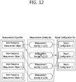
- FIG. 12 illustrates an example of deleting a measurement identity.
- a measurement for a measurement object associated with the measurement identity 2 1202 is stopped and a measurement report is not also transmitted.
- the measurement object or the report configuration associated with the deleted measurement identity may not be changed.
- FIG. 13 illustrates an example of deleting a measurement object.
- the UE When the inter-frequency measurement object 1 is deleted, the UE also deletes the associated measurement identity 3 1303. The measurement for the inter-frequency measurement object 1 is stopped and the measurement report is not also transmitted. However, the report configuration associated with the deleted first inter-frequency measurement object may not be changed or deleted.
- the UE When the report configuration is removed, the UE removes even the associated measurement identity. The UE stops measuring the associated measurement object by the associated measurement identity. However, the measurement object associated with the deleted report configuration may not be changed or deleted.
- the measurement report may include the measurement identity, a measured quality of the serving cell, and a measurement result of the neighboring cell.
- the measurement identity identifies a measurement object in which the measurement report is triggered.
- the measurement result of the neighboring cell may include a cell identity and a measured quality of the neighboring cell.
- the measured quality may include at least one of reference signal received power (RSRP) and reference signal received quality (RSRQ).
- H(e)NB will be described.
- the mobile communication service may be provided through a person, a specific operator, or a base station possessed by a group in addition to the mobile communication network operator.
- the base station is called Home NB (HNB) or Home eNB (HeNB).
- HNB Home NB
- HeNB Home eNB
- both the HNB and HeNB are collectively the HeNB.
- the HeNB aims at basically providing a service specialized to only a closed subscriber group (CSG). However, the service may be provided to users other than the CSG according to a configuration of an operating mode of the HeNB.
- FIG. 14 is a diagram illustrating one example of a wireless communication system illustrating a HeNB operation.
- a Home eNB gateway may be operated in order to service the HeNB as such.
- the HeNBs is connected to the EPC through the HeNB GW or connected directly to the EPC.
- the HeNB GW is seen as a general eNB for the MME.
- the HeNB GW is seen as the MME for the HeNB. Therefore, the HeNB and the HeNB GW are connected to each other through an S1 interface and the HeNB GW and the EPC are also connected to each other through the S1 interface. Further, even when the HeNB and the EPC are directly connected to each other, the HeNB and the EPC are connected to each other through the S1 interface. Most functions of the HeNB are similar to those of a general eNB.
- the HeNB is lower than an eNB possessed by the mobile communication operator in radio transmission output. Therefore, service coverage provided by the HeNB is generally smaller than that provided by the eNB. Due to such a feature, a cell provided by the HeNB is often classified as a femto cell as compared with a macro cell provided by the eNB in terms of the service coverage. Meanwhile, in terms of the provided service, when the HeNB provides the service to only the CSG, the cell provided by the HeNB is called a CSG cell.
- Each CSG has its own unique identification number and the identification number is called a CSG identity (ID).
- ID The UE may have a list of the CSG to which the UE belongs as a member and the CSG list may be changed by a request from the UE or a command of the network.
- one HeNB may support one CSG.
- the HeNB transfers a CSG ID of a CSG supported thereby through the system information to be accessed by only the member UE of the corresponding CSG.
- the UE may verify which CSG the CSG cell supports by reading the CSG ID included in the system information.
- the UE that reads the CSG ID regards the corresponding cell as a cell capable of access only when the UE itself is a member of the corresponding CSG cell.
- the HeNB need not permit only the CSG UE to access itself.
- the HeNB may also permit a UE which is not the CSG member to access itself according to a configuration of the HeNB. Which UE the HeNB permits to access itself depends on the configuration of the HeNB and herein, the configuration means a configuration of an operating mode of the HeNB.
- the operating mode of the HeNB is divided into three types described below by considering which UE the HeNB provides the service to.
- Closed access mode Represents a mode to provide the service to a specific CSG member.
- the HeNB provides the CSG cell.
- Open access mode Represents a mode to provide the service without a limitation of the specific CSG member like a general eNB.
- the HeNB provides not the CSG cell but the general cell.
- Hybrid access mode Represents a mode to provide a CSG service to the specific CSG member and provide the service to even a non-CSG member like the general cell. Recognized as the CSG cell by the CSG member UE and recognized as the general cell by the non-CSG member UE. Such a cell is called a hybrid cell.
- the HeNB notifies whether a cell serviced thereby is the CSG cell or the general cell to the UE to allow the UE to know whether the UE may access the corresponding cell.
- the HeNB operated in the closed access mode broadcasts that the HeNB itself is the CSG cell through the system information.
- the HeNB operated in the open access mode broadcasts that the HeNB itself is not the CSG cell through the system information.
- the HeNB encapsulates a 1-bit CSG indicator indicating whether the cell serviced thereby is the CSG cell in the system information. For example, the HeNB broadcasts that the serviced cell is the CSG cell by setting the CSG indicator as TRUE.
- the CSG indicator may be set as FALSE or a method that skips transmitting the CSG indicator may be used. Since the UE needs to be able to distinguish the general cell provided by the eNB from the CSG cell, the general eNB also transmit the CSG indicator to allow the UE to know that the cell type provided thereby is the general cell. The general eNB does not transmit the CSG indicator to allow the UE to know that the cell type provided thereby is the general cell. Table 2 illustrates a CSG associated parameter transmitted in a corresponding cell for each cell type. Subsequently,
- Table 3 illustrates a type of a UE that permits the access for each cell type.
- CSG cell General cell CSG indicator Indicating 'CSG cell' Indicating 'Non-CSG cell' or not transmitted CSG identity Transmitting supported CSG identity Not transmitted
- CSG cell General cell UE not supporting CSG Inaccessible Accessible Non-CSG member UE Inaccessible Accessible Member CSG UE Accessible Accessible
- inter-cell interference coordination (ICIC) will be described.
- the ICIC is a task that operates a radio resource so that a control of inter-cell interference is maintained.
- An ICIC mechanism may be divided into frequency-domain ICIC and time-domain ICIC.
- the ICIC has a multi-cell radio resource management (RRM) function to require considering information from multiple cells.
- RRM radio resource management
- An interfering cell is a cell that provides interference.
- the interfering cell is also referred as an aggressor cell.
- An interfered cell is a cell that is interfered by the interfering cell.
- the interfered cell is also referred to as a victim cell.
- the frequency-domain ICIC coordinates the use of a frequency-domain resource (e.g., a resource block (RB)) among the multiple cells.
- a frequency-domain resource e.g., a resource block (RB)
- the time-domain ICIC coordinates a time-domain resource (e.g., a subframe) among the multiple cells.
- An operations, administration, and maintenance (OAM) configuration called an almost blank subframe (ABS) pattern may be used for the time-domain ICIC.
- An ABS in the interfering cell is used to protect a resource in the subframe in the interfered cell that receives interference among strong cells.
- the ABS is a subframe that has reduced transmission power (alternatively, zero transmission power) on the physical channel or has reduced activity.
- a pattern based on the ABS is notified to the UE and restricts a UE measurement. This restriction is referred to as a measurement resource restriction.
- the ABS pattern represents information indicating which subframe is the ABS in one or more radio frames.
- a measured cell e.g., a serving cell or a neighbor cell
- measurement types e.g., a radio resource management (RRM), a radio link measurement (RLM), and channel state information (CSI)
- ABS pattern 1' is used in an RRM/RLM measurement resource restriction of the serving cell.
- the base station may notify information on ABS pattern 1 to the UE in configuration/modification/release of the RB or when MAC/ PHY configuration is modified.
- ABS pattern 2' is used in an RRM measurement resource restriction of the neighbor cell that operates at the same frequency as the serving cell. Therefore, a list of neighbor cells to be measured in addition to information on ABS pattern 2 may be provided to the UE. ABS pattern 2 may be included in a measurement configuration for a measurement object.
- ABS pattern 3' is used in a resource restriction for a CSI measurement of the serving cell.
- ABS pattern 3 may be included in a message for configuring a CSI report.
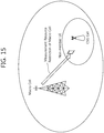
- FIG. 15 exemplifies a CSG scenario.
- the CSG cell represents a cell accessible by only a specific subscriber.
- the non-member UE as a UE which is not the member of the CSG cell is UE that does not access the CSG cell.
- the CSG cell which the UE may not access is referred to as the non-member CSG cell.
- the macro cell represents the serving cell of the non-member UE. Coverage of the CSG cell and coverage of the macro cell are partially or fully duplicated with each other.
- a primary interference condition occurs when the non-member UE is positioned in close proximity with the CSG cell.
- the interfering cell becomes the CSG cell and the macro cell becomes the interfered cell.
- the time-domain ICIC is used so as for the non-member UE to continuously receive the service in the macro cell.
- the network may configure a measurement resource restriction. Further, in order to facilitate mobility from the macro cell, the network may configure an RRM measurement resource restriction for the neighbor cell. When the UE is not strongly interfered from the CSG cell any longer, the network may release the RRM/RLM/CSI measurement resource restriction.
- the UE may use the measurement resource restrictions configured for the RRM, RLM, and CSI measurement. That is, a resource for the RLM may be used in the ABS, and the measurement for the RLM and the CSI measurement may be performed in the ABS.
- the network may configure the CSG cell not to use a low-interference radio resource depending on the configured measurement resource restriction. That is, the CSG cell may not transmit or receive data in the ABS.
- FIG. 16 exemplifies a pico scenario.
- a pico cell is a serving cell of a pico UE.
- the pico cell is a cell of which coverage is partially or fully duplicated with the coverage of the macro cell.
- the pico cell may generally have smaller coverage than the macro cell, but the present invention is not particularly limited thereto.
- the primary interference condition occurs when the pico UE is positioned at an edge of the pico serving cell.
- the interfering cell becomes the macro cell and the pico cell becomes the interfered cell.
- the time-domain ICIC is used so as for the pico UE to continuously receive the service in the pico cell.
- the pico cell may configure the measurement resource restriction for the corresponding UE.
- the pico UE may use the measurement resource restrictions configured for the RRM, RLM, and CSI measurement. That is, the resource for the RLM may be used in the ABS, and the measurement for the RLM and the CSI measurement may be performed in the ABS. When the pico cell is strongly interfered from the macro cell, a more accurate measurement is possible in the case where the RRM/RLM/CSI measurement is performed in the ABS.
- the UE in the macro cell as the serving cell performs the measurement for the neighbor cell in the ABS, mobility from the macro cell to the pico cell may be facilitated.
- the UE performs the RRM measurement such as the reference signal received power (RSRP) and the reference signal received quality (RSRQ), a measurement of quality such as a channel quality indicator (CQI), and a path-loss measurement for the serving cell or the neighbor cell. Further, the UE may perform a measurement for radio link monitoring (RLM) for monitoring a connection with the serving cell.
- RRM radio link monitoring
- the interfering cell and the interfered cell are decided depending on an object which the UE intends to measure.
- an intra-frequency neighbor cell having a high signal strength near the UE may act as interference in a measurement for the serving cell.
- the UE may undergo strong interference by the neighbor cell in the measurement for the serving cell.
- serving cell and other intra-frequency neighbor cell signals may act as the interference for the measurement of the intra-frequency neighbor cell.
- the UE may undergo strong interference by the serving cell and other neighbor cells of a serving frequency in the measurement of the neighbor cell.
- the interfered UE may perform a limited measurement based on the measurement resource restriction.
- the serving cell may provide the service the UE through scheduling primarily using a low-interference radio resource in spite of the interference by the neighbor cell.
- a multimedia broadcast/multicast service is a service to provide multimedia data to the UE in the cell.
- An MCH channel which is a transmission channel for the MBMS may be mapped to the MCCH or the MTCH which is the logical channel.
- the MCCH transmits an RRC message associated with the MBMS and the MTCH transmits traffic of a specific MBMS.
- a plurality of MCHs may be used according to capacities of the MTCH and the MCCH in one cell.
- the MCH is in charge of transmitting two logical channels of the MTCH and the MCCH, and is again mapped to a physical multicast channel (PMCH) which is the physical channel.
- PMCH physical multicast channel
- One MCCH is present in one MBMS single frequency network (MBSFN) region transmitting the same MBMS information/traffic, and when a plurality of MBSFN regions are provided in one cell, the UE may receive a plurality of MCCHs.
- M_RNTI MBMS radio network temporary identity
- a UE that supports the MBMS receives the M-RNTI and the MCCH indicator through the PDCCH to determine that the MBMS associated RRC message is changed in the specific MCCH and receive the specific MCCH.
- the RRC message of the MCCH may be changed every change cycle and is repeatedly broadcasted every repetition cycle.
- the existing wireless network may calculate the number of UEs that receives a specific service through a counting procedure.
- the counting procedure is configured in such a manner that the UE transmits an uplink counting response message when the wireless network transmits a downlink counting request message.
- the UE may have had system information about corresponding neighboring cell before it is requested to report the system information about the neighboring cell from a serving cell.
- the UE when the UE receives a system information reporting request from the serving cell, the UE does not move to the neighboring cell and does not acquire the system information and may report ready-acquired system information to the serving cell.
- UE may send validity information indicating whether the corresponding information is valid or not of providing a criterion for determining whether the corresponding information is valid or not.
- a serving cell may request the UE to transmit validity information about the specific information.
- the UE may transmit the validity information to the serving cell in response to the request or may arbitrarily transmit the validity information to the serving cell.
- the validity information may be transmitted independently from the specific information or may be included in a message including the specific information and transmitted. If the validity information is independently transmitted, the validity information may be transmitted in response to a request from the serving cell after the specific information is transmitted and received.
- the validity information may be transmitted in response to a request from the serving cell or arbitrarily transmitted before the specific information is transmitted and received.
- the serving cell may determine whether the specific information is valid or not based on the corresponding validity information.
- a method of transmitting and receiving validity information can be applied to a system information report method in which UE sends system information to a serving cell in response to a system information report request from the serving cell.
- UE may report validity information about the ready-acquired system information to the serving cell.
- FIG. 17 is a diagram showing an example of a method of reporting system information in accordance with an embodiment of the present invention.
- the serving cell may include information, indicating that validity information should be reported, in the system information reporting request and transmit the system information reporting request.
- the validity information report indication information may include an indicator having a 1-bit size that indicates that validity information should be reported.
- the validity information report indication information may include one or more cell identifiers indicative of one or more neighboring cells that are considered to be the subjects of validity information.
- the serving cell may instruct the UE to report only system information whose time that has elapsed after acquiring the system information is a specific threshold or lower.
- the system information may include a threshold in the system information reporting request and be transmitted
- the UE does not perform an additional procedure for acquiring system information about the neighboring cell and reports the ready-acquired system information to the serving cell (S1720).
- the UE may include the ready-acquired system information in a system information report and transmit the system information report to the serving cell. If the UE reports the ready-acquired system information to the serving cell, the UE includes validity information about the corresponding system information in the system information report and sends the system information report.
- the UE is able to send validity information to the serving cell only when the UE has had system information about a neighboring cell that was acquired before receiving a system information reporting request from the serving cell and the UE reports the system information to the serving cell. If the UE reports the system information acquired after receiving the system information report request to the serving cell, the UE may not report validity information.
- the validity information transmitted to the serving cell may include pieces of the following detailed information. Specific information of the pieces of listed information or a combination of the pieces of listed information can be transferred to a serving cell as validity information.
- the serving cell determines whether the system information is valid or not based on the received validity information (S1730).
- the serving cell may determine whether the reported system information is valid or not based on time-related information that is included in the validity information. For example, the serving cell may determine the system information included in the validity information to be valid if a specific time value or more has not elapsed from a point of time at which the system information was acquired from the neighboring cell.
- the specific time value may be a value that has been previously determined in a network. For example, if the version of serving cell system information is determined to be the same as that of system information of the serving cell when acquiring the system information included in the validity information, the serving cell may determine the system information to be valid system information.
- the serving cell may determine that the system information is valid system information.
- One or more of the aforementioned examples in which validity is determined may be combined.
- the serving cell may transmit a system information reporting request to the UE.
- Information indicating that validity information should be reported may not be included in the system information reporting request, and the system information reporting request may be transmitted.
- the system information reporting request may include information indicating that system information should be acquired from a neighboring cell and reported.
- the UE may receive the system information reporting request, access the neighboring cell, acquiring the system information, and report the acquired system information to the serving cell.
- the serving cell may transfer the validity information for the reported system information and/or the system information to the neighboring cell, if necessary (S1740). If the system information reported by the UE is determined to be not valid as a result of determining validity based on the validity information, the serving cell may transfer the validity information and/or the system information to the neighboring cell. This is for requesting the neighboring cell to directly determine whether the reported system information is valid or not and to report a result of the determination.
- the neighboring cell may determine validity information for the received system information based on the validity information and/or the system information (S1750).
- the neighboring cell may determine whether the reported system information is valid or not based on time-related information included in the validity information. For example, the neighboring cell may determine that the system information is valid if a specific time value or more does not elapse from a point of time at which the system information was acquired from the neighboring cell.
- the specific time value may be a value predetermined in a network. For example, if the version of the system information included in the validity information is the same as that of system information about the neighboring cell, the neighboring cell may determine that the system information is valid system information.
- One or more of the aforementioned examples in which validity is determined may be combined.
- FIG. 18 is a diagram showing another example of a method of reporting system information in accordance with an embodiment of the present invention. It is assumed that UE has previously obtained system information about a neighboring cell A.
- the UE receives a system information reporting request for the neighboring cell A from a serving cell (S1810). Unlike in the system information reporting request of FIG. 17 , validity information report indication information that instructs validity information to be reported may not be transferred to the UE.
- the UE determines whether or not ready-acquired system information about the neighboring cell A is present. Since the ready-acquired system information is present, the UE transmits a system information report, including the ready-acquired system information about the cell A, to the serving cell (S1820). When reporting the ready-acquired system information about the neighboring cell A, the UE may include validity information for the corresponding system information in the system information report and send the system information report.
- S1730 to S1750 of FIG. 17 can be for the procedures of the serving cell after receiving the ready-acquired system information about the neighboring cell A and the validity information from the UE.
- the UE receives a system information reporting request for a neighboring cell B from the serving cell (S1830). Validity information report indication information may not be included in the system information reporting request for the neighboring cell B.
- the UE When receiving the system information reporting request for the neighboring cell B from the serving cell, the UE determines whether or not ready-acquired system information about the neighboring cell B is present.
- the UE receives/acquires system information from the neighboring cell B (S1840). In order to obtain the system information about the cell B, the UE leaves the serving cell and accesses the neighboring cell. The UE receives the system information from the neighboring cell and then accesses the serving cell again.
- the UE reports the system information, obtained from the neighboring cell B, to the serving cell (S1850). Since the system information about the cell B that is reported by the UE is not system information acquired prior to the reception of the system information report request for the neighboring cell B, the UE includes the system information about the cell B in a system information report and transmit the system information report, but may not include validity information in the system information report.
- the serving cell may notify the UE whether or not the UE is allowed to report ready-acquired system information about a specific neighboring cell.
- the serving cell may send a ready-acquired system information report indicator to the UE along with the system information reporting request. If the ready-acquired system information report indicator is used, the UE may report the system information to the serving cell based on the ready-acquired system information report indicator.
- the serving cell may report ready-acquired system information about the neighboring cell to the serving cell. If the UE has received a system information report request, but has not receive a ready-acquired system information report indicator, the UE accesses a neighboring cell, acquires system information, and reports the acquired system information to the serving cell. In this case, when transmitting the system information to the serving cell, the UE does not send validity information. Accordingly, thereafter, the serving cell does not determine validity for the system information reported by the UE and does not request the neighboring cell to determine validity for the reported system information by sending the system information to the neighboring cell.
- the UE may report ready-acquired system information about the cell A to the serving cell. If the UE has received a system information reporting request, but has not received a ready-acquired system information report indicator, the UE accesses the neighboring cell, acquires system information, and reports the acquired system information to the serving cell. In this case, when reporting the system information to the serving cell, the UE does not send validity information.
- the UE may include information, indicating that system information included in a system information report message is ready-acquired system information previously acquired prior to a report request, in the system information report message and sends the system information report message.
- UE may store specific system information about a neighboring cell for a specific time or more.
- the UE may store the system information about the cell in order to subsequently report the system information about the cell.
- the UE may be allowed to store the system information for a time that exceeds a common valid time of system information.
- the system information that is reported from the UE to the serving cell may include pieces of the following detailed information.
- reported system information may include CSG-related information about the cell, such as a CSG identifier or CSG indicator.
- reported system information may include MBMS-related information about the cell, such as MBMS service information, MBMS configuration information, MBMS scheduling information, frequency information about provided MBMS service and/or MBSFN subframe information.
- reported system information may include low interference radio resource-related information about the cell, such as ABS pattern information, low interference subframe pattern information, or a limited measurement pattern.
- the reported system information may include access limit-related information, such as an access class-barring parameter.
- the reported system information may be information about one or more uplink frequency bands associated with the downlink of a specific cell.
- the serving cell when a serving cell requests that system information about a neighboring cell be reported, the serving cell may transfer a system information indicator, indicating that specific individual information belonging to the system information about the neighboring cell should be reported, to UE.
- the system information indicator may be implemented so that a report on information corresponding to the indicator is requested in such a manner that one system information indicator indicates one or more types of information.
- the system information indicator may be implemented so that one or more specific types of information are requested through the transmission of one or more system information indicators in such a manner that one indicator indicates a specific type of information.
- the system information indicator may be included in a measurement configuration and transmitted and may be transmitted along with a system information report request.
- the system information indicator may be included in a target measurement configuration and/or a measurement report configuration.
- Specific information that is requested to be reported may be at least one of CSG-related information, MBMS-related information low interference radio resource-related information, access limit-related information, and information about one or more uplink frequency bands associated with the downlink of a specific cell.
- UE in reporting ready-acquired system information and/or system information, newly acquired after a system information report request, to a serving cell, UE may transmit the read-acquired system information and/or the newly acquired system information to the serving cell along with specific information that has been determined/processed based on the corresponding system information.
- the specific information may include information indicating whether or not UE is a member of a CSG regarding a corresponding neighboring cell.
- the specific information may include information indicating whether or not UE can access a corresponding neighboring cell.
- the specific information may include information indicating whether or not UE can be supplied with desired specific service from a corresponding neighboring cell.
- the specific information may include information indicating whether or not the UE can be served with MBMS information from the cell.
- the specific information may be information indicating whether or not specific radio resources can be configured for UE in a corresponding neighboring cell.
- the specific information may be information indicating whether or not UE can camp on in the cell.
- the specific information may be information indicating whether or not the cell is a cell suitable for UE.
- the specific information may be information indicating whether or not the cell is a cell that may be used by UE as a serving cell through a carrier aggregation or may be system information necessary to configure the cell as a serving cell through a carrier aggregation.
- the specific information may include information indicating whether or not a corresponding neighboring cell is a cell that may be used by UE as an additional serving cell Pcell or Scell.
- a network can effectively determine whether system information reported by UE is valid or not. Accordingly, a serving cell can exclude invalid system information about a neighboring cell, thereby being capable of preventing a wrong operation. Furthermore, a network can further trust system information about a neighboring cell that has been reported by UE through a proper validity check, and overhead for UE that directly receives system information from a neighboring cell and reports the received system information can be reduced. If such effects of the present invention are applied to a system information check handover procedure of a target cell, a user's communication quality can be improved because handover delay is reduced.
- FIG. 19 is a block diagram showing a wireless device in which an embodiment of the present invention can be implemented.
- the device can implement UE that performs and/or a BS of a serving cell or a neighboring cell which perform the system report method in accordance with the embodiments of FIG. 17 and 18 .
- the wireless device 1900 includes a processor 1910, memory 1920, and a Radio Frequency (RF) unit 1930.
- the processor 1910 implements the proposed functions, processes and/or methods.
- the processor 1910 can be configured to report system information about a neighboring cell to a serving cell in response to a system information reporting request.
- the processor 1910 can be configured to report ready-acquired system information about a neighboring cell to be reported to a serving cell if the ready-acquired system information about the neighboring cell is present.
- the processor 1910 can be configured to report validity information to a serving cell along with ready-acquired system information when reporting the ready-acquired system information to the serving cell.
- the processor 1910 can be configured to report validity information to a serving cell in response to validity information report indication information.
- the processor 1910 can be configured to determine whether corresponding system information is valid or not when receiving ready-acquired system information and validity information are received from UE.
- the processor 1910 can be configured to implement the methods of reporting system information in accordance with the aforementioned embodiments of FIGS. 17 and 18 .
- the RF unit 1930 is connected to the processor 1910 and sends and receives radio signals.
- the processor 1910 may include Application-Specific Integrated Circuits (ASICs), other chipsets, logic circuits, and/or data processors.
- the memory 1920 may include Read-Only Memory (ROM), Random Access Memory (RAM), flash memory, memory cards, storage media and/or other storage devices.
- the RF unit 1930 may include baseband circuits for processing radio signals.
- the aforementioned scheme may be implemented as a module (process or function) that performs the aforementioned function.
- the module may be stored in the memory 1920 and executed by the processor 1910.
- the memory 1920 may be placed inside or outside the processor 1910 and may be connected to the processor 1910 using a variety of well-known means.
Landscapes
- Engineering & Computer Science (AREA)
- Computer Networks & Wireless Communication (AREA)
- Signal Processing (AREA)
- Mobile Radio Communication Systems (AREA)
Claims (15)
- Verfahren zur Meldung von Systeminformationen in einem drahtlosen Kommunikationssystem durch ein Benutzergerät (1900), wobei das Verfahren aufweist:Empfangen einer Anfrage für die Meldung von Systeminformationen über eine Nachbarzelle von einer betreuenden Zelle; undansprechend auf die Anfrage für die Meldung von Systeminformationen Übertragen einer Meldung von Systeminformationen an die betreuende Zelle,wobei:wenn das Benutzergerät (1900) bereits erlangte Systeminformationen über die Nachbarzelle hatte, die erlangt wurden, bevor die Anfrage für die Meldung von Systeminformationen empfangen wurde, das Benutzergerät (1900) die bereits erlangten Systeminformationen und Gültigkeitsinformationen für die bereits erlangten Systeminformationen als die Meldung von Systeminformationen überträgt, undwenn das Benutzergerät (1900) keine bereits erlangten Systeminformationen über die Nachbarzelle hat, wenn das Benutzergerät (1900) die Anfrage für die Meldung von Systeminformationen empfängt, das Benutzergerät (1900) auf die Nachbarzelle zugreift, Systeminformationen gewinnt und die gewonnenen Systeminformationen als die Meldung von Systeminformationen überträgt.
- Verfahren nach Anspruch 1, das ferner das Zugreifen auf die Nachbarzelle und das Gewinnen von Systeminformationen aufweist, wenn das Benutzergerät (1900) die bereits erlangten Systeminformationen nicht hat,
wobei die Meldung von Systeminformationen die Systeminformationen aufweist. - Verfahren nach Anspruch 2, wobei die betreuende Zelle basierend auf den Gültigkeitsinformationen bestimmt, ob die bereits erlangten Systeminformationen gültige Systeminformationen sind.
- Verfahren nach Anspruch 3, wobei die Gültigkeitsinformationen Erlangungszeitinformationen aufweisen, die einen Zeitpunkt anzeigen, zu dem die bereits erlangten Systeminformationen von der Nachbarzelle erlangt wurden.
- Verfahren nach Anspruch 4, wobei der Schritt des Bestimmens, ob die bereits erlangten Systeminformationen gültige Systeminformationen sind oder nicht, aufweist:
Bestimmen, dass die bereits erlangten Systeminformationen gültige Systeminformationen sind, wenn eine Zeit, die seit dem Zeitpunkt, der durch die Erlangungszeitinformationen angezeigt wird, vergangen ist, ein spezifischer Wert oder kleiner ist. - Verfahren nach Anspruch 3, wobei die Gültigkeitsinformationen einen Wertmarker aufweisen, der eine Version von Systeminformationen anzeigt, die durch das Benutzergerät (1900) von der betreuenden Zelle zu dem Zeitpunkt empfangen werden, zu dem die bereits erlangten Systeminformationen von der Nachbarzelle empfangen werden.
- Verfahren nach Anspruch 6, wobei der Schritt des Bestimmens, ob die bereits erlangten Systeminformationen gültige Systeminformationen sind oder nicht, aufweist:
Bestimmen, dass die bereits erlangten Systeminformationen gültige Systeminformationen sind, wenn die Version, die durch den Wertmarker angezeigt wird, identisch mit einer Version von Systeminformationen der betreuenden Zelle ist, wenn die Bestimmung vorgenommen wird. - Verfahren nach Anspruch 1, wobei:die Anfrage für die Meldung von Systeminformationen einen Gültigkeitsinformationsmeldungsindikator aufweist, der anzeigt, dass die Gültigkeitsinformationen zusammen mit den bereits erlangten Systeminformationen übertragen werden müssen, unddie Gültigkeitsinformationen in der Meldung von Systeminformationen enthalten sind und übertragen werden, wenn der Gültigkeitsinformationsmeldungsindikator in der Anfrage für die Meldung von Systeminformationen enthalten ist.
- Benutzergerät (1900), das in einem drahtlosen Kommunikationssystem arbeitet, wobei das Benutzergerät (1900) aufweist:eine Funkfrequenz-, RF-, Einheit (1930), die Funksignale sendet und empfängt; undeinen Prozessor (1910), der funktional mit der RF-Einheit (1930) verbunden ist, wobei der Prozessor (1910) konfiguriert ist, um:eine Anfrage für die Meldung von Systeminformationen über eine Nachbarzelle von einer betreuenden Zelle zu empfangen; undansprechend auf die Anfrage für die Meldung von Systeminformationen eine Meldung von Systeminformationen an die betreuende Zelle zu übertragen,wobei:wenn das Benutzergerät (1900) bereits erlangte Systeminformationen über die Nachbarzelle hatte, die erlangt wurde, bevor die Anfrage für die Meldung von Systeminformationen empfangen wurden, der Prozessor (1910) ferner konfiguriert ist, um die bereits erlangten Systeminformationen und Gültigkeitsinformationen für die bereits erlangten Systeminformationen als die Meldung von Systeminformationen zu übertragen, undwenn das Benutzergerät (1900) keine bereits erlangten Systeminformationen über die Nachbarzelle hat, wenn das Benutzergerät (1900) die Anfrage für die Meldung von Systeminformationen empfängt, der Prozessor (1910) ferner konfiguriert ist, um auf die Nachbarzelle zuzugreifen, Systeminformationen zu gewinnen und die gewonnenen Systeminformationen als die Meldung von Systeminformationen zu übertragen.
- Benutzergerät (1900) nach Anspruch 9, wobei der Prozessor (1910) konfiguriert ist, um auf die Nachbarzelle zuzugreifen und Systeminformationen zu gewinnen, wenn das Benutzergerät (1900) die bereits erlangten Systeminformationen nicht hat,
wobei die Meldung von Systeminformationen die Systeminformationen aufweist. - Benutzergerät (1900) nach Anspruch 10, wobei die betreuende Zelle basierend auf den Gültigkeitsinformationen bestimmt, ob die bereits erlangten Systeminformationen gültige Systeminformationen sind.
- Benutzergerät (1900) nach Anspruch 11, wobei die Gültigkeitsinformationen Erlangungszeitinformationen aufweisen, die einen Zeitpunkt anzeigen, zu dem die bereits erlangten Systeminformationen von der Nachbarzelle erlangt wurden.
- Benutzergerät (1900) nach Anspruch 12, wobei das Bestimmen, ob die bereits erlangten Systeminformationen gültige Systeminformationen sind oder nicht, aufweist:
Bestimmen, dass die bereits erlangten Systeminformationen gültige Systeminformationen sind, wenn eine Zeit, die seit dem Zeitpunkt, der durch die Erlangungszeitinformationen angezeigt wird, vergangen ist, ein spezifischer Wert oder kleiner ist. - Benutzergerät (1900) nach Anspruch 11, wobei die Gültigkeitsinformationen einen Wertmarker aufweisen, der eine Version von Systeminformationen anzeigt, die durch das Benutzergerät (1900) von der betreuenden Zelle zu dem Zeitpunkt empfangen werden, zu dem die bereits erlangten Systeminformationen von der Nachbarzelle empfangen werden.
- Benutzergerät (1900) nach Anspruch 14, wobei das Bestimmen, ob die bereits erlangten Systeminformationen gültige Systeminformationen sind oder nicht, aufweist:
Bestimmen, dass die bereits erlangten Systeminformationen gültige Systeminformationen sind, wenn die Version, die durch den Wertmarker angezeigt wird, identisch mit einer Version von Systeminformationen der betreuenden Zelle ist, wenn die Bestimmung vorgenommen wird.
Applications Claiming Priority (2)
| Application Number | Priority Date | Filing Date | Title |
|---|---|---|---|
| US201161507606P | 2011-07-14 | 2011-07-14 | |
| PCT/KR2012/005583 WO2013009130A2 (ko) | 2011-07-14 | 2012-07-13 | 무선 통신 시스템에서 시스템 정보 보고 방법 및 이를 지원하는 장치 |
Publications (3)
| Publication Number | Publication Date |
|---|---|
| EP2733985A2 EP2733985A2 (de) | 2014-05-21 |
| EP2733985A4 EP2733985A4 (de) | 2015-06-17 |
| EP2733985B1 true EP2733985B1 (de) | 2019-06-19 |
Family
ID=47506738
Family Applications (4)
| Application Number | Title | Priority Date | Filing Date |
|---|---|---|---|
| EP12810805.7A Active EP2733981B1 (de) | 2011-07-14 | 2012-07-13 | Verfahren zum berichten in einem drahtlosen kommunikationssystem und vorrichtung zur ausführung dieses verfahrens |
| EP12812065.6A Not-in-force EP2733985B1 (de) | 2011-07-14 | 2012-07-13 | Verfahren zur meldung von systeminformationen in einem drahtlosen kommunikationssystem und vorrichtung zur unterstützung des verfahrens |
| EP12811044.2A Not-in-force EP2747481B1 (de) | 2011-07-14 | 2012-07-13 | Verfahren zur meldung von systeminformationen in einem drahtlosen kommunikationssystem und vorrichtung zu ihrer unterstützung |
| EP12811689.4A Not-in-force EP2733984B1 (de) | 2011-07-14 | 2012-07-13 | Verfahren zur meldung von systeminformationen in einer drahtlosen kommunikation und vorrichtung zur unterstützung des verfahrens |
Family Applications Before (1)
| Application Number | Title | Priority Date | Filing Date |
|---|---|---|---|
| EP12810805.7A Active EP2733981B1 (de) | 2011-07-14 | 2012-07-13 | Verfahren zum berichten in einem drahtlosen kommunikationssystem und vorrichtung zur ausführung dieses verfahrens |
Family Applications After (2)
| Application Number | Title | Priority Date | Filing Date |
|---|---|---|---|
| EP12811044.2A Not-in-force EP2747481B1 (de) | 2011-07-14 | 2012-07-13 | Verfahren zur meldung von systeminformationen in einem drahtlosen kommunikationssystem und vorrichtung zu ihrer unterstützung |
| EP12811689.4A Not-in-force EP2733984B1 (de) | 2011-07-14 | 2012-07-13 | Verfahren zur meldung von systeminformationen in einer drahtlosen kommunikation und vorrichtung zur unterstützung des verfahrens |
Country Status (4)
| Country | Link |
|---|---|
| US (4) | US9307456B2 (de) |
| EP (4) | EP2733981B1 (de) |
| KR (4) | KR20140040808A (de) |
| WO (4) | WO2013009130A2 (de) |
Families Citing this family (22)
| Publication number | Priority date | Publication date | Assignee | Title |
|---|---|---|---|---|
| WO2013009130A2 (ko) * | 2011-07-14 | 2013-01-17 | 엘지전자 주식회사 | 무선 통신 시스템에서 시스템 정보 보고 방법 및 이를 지원하는 장치 |
| KR102100194B1 (ko) * | 2013-03-15 | 2020-04-13 | 엘지전자 주식회사 | 객체의 측정을 수행하는 방법 및 이를 위한 장치 |
| WO2014148812A1 (ko) * | 2013-03-19 | 2014-09-25 | 엘지전자 주식회사 | 다중 셀 기반 무선 통신 시스템에서 단말이 신호를 송수신하는 방법 및 이를 위한 장치 |
| TW201501477A (zh) * | 2013-04-03 | 2015-01-01 | Interdigital Patent Holdings | 小胞元部署增強干擾協調機制 |
| CN104602344B (zh) * | 2013-10-30 | 2019-02-12 | 电信科学技术研究院 | 一种组通信信息通知方法及设备 |
| CN105934969B (zh) * | 2014-01-29 | 2019-04-05 | Lg电子株式会社 | 在无线通信系统中发送报告消息的方法和装置 |
| WO2016053066A1 (ko) * | 2014-10-03 | 2016-04-07 | 엘지전자(주) | 무선 통신 시스템에서 셀 단위 보고를 위한 방법 및 이를 위한 장치 |
| WO2016104818A1 (ko) * | 2014-12-22 | 2016-06-30 | 엘지전자 주식회사 | 무선 통신 시스템에서 서빙 기지국으로 무빙 셀 측정 보고 신호를 전송하는 방법 및 이를 위한 장치 |
| US10462839B2 (en) | 2015-04-08 | 2019-10-29 | Lg Electronics Inc. | Method for transmitting sidelink terminal information of terminal in wireless communication system and terminal utilizing the method |
| JP6313904B2 (ja) * | 2015-04-10 | 2018-04-18 | 京セラ株式会社 | 基地局、通信方法及びプロセッサ |
| CN107637124B (zh) * | 2015-05-16 | 2021-08-27 | Lg电子株式会社 | 终端在无线通信系统中计算再分配范围的方法和装置 |
| CN106489274B (zh) * | 2015-06-23 | 2020-03-31 | 海能达通信股份有限公司 | 一种处于rrc空闲态终端移动控制方法、终端及基站 |
| WO2017166244A1 (zh) * | 2016-03-31 | 2017-10-05 | 华为技术有限公司 | 多播传输方法、基站和用户设备 |
| US10425926B2 (en) * | 2016-05-10 | 2019-09-24 | Lg Electronics Inc. | Method and apparatus for requesting additional system information |
| KR20190034629A (ko) * | 2016-08-12 | 2019-04-02 | 후아웨이 테크놀러지 컴퍼니 리미티드 | 데이터 처리 방법 및 관련 장치 |
| EP3501206B1 (de) * | 2016-08-17 | 2020-05-27 | Telefonaktiebolaget LM Ericsson (publ) | Risikobewusste validitätsbewertung von systeminformationen |
| WO2018066922A1 (ko) * | 2016-10-03 | 2018-04-12 | 엘지전자 주식회사 | 시스템 정보 블록의 유효성 검사를 수행하는 방법 및 이를 지원하는 장치 |
| WO2019012430A1 (en) * | 2017-07-14 | 2019-01-17 | Telefonaktiebolaget Lm Ericsson (Publ) | ACQUIRING SYSTEM INFORMATION DURING TRANSFER |
| EP3664501A4 (de) * | 2017-08-11 | 2020-07-15 | Huawei Technologies Co., Ltd. | Messverfahren, vorrichtung und system |
| CN107948950A (zh) * | 2017-11-15 | 2018-04-20 | 北京佰才邦技术有限公司 | 系统信息变更的通知方法、终端、接入设备、计算机存储介质以及系统 |
| KR102427925B1 (ko) | 2018-03-05 | 2022-08-02 | 삼성전자주식회사 | 안테나를 통해 출력된 신호에 기반하여 결정된 외부 객체와의 거리에 따라, 지정된 기능을 수행하는 전자장치 및 방법 |
| KR20200112288A (ko) * | 2019-03-21 | 2020-10-05 | 삼성전자주식회사 | 무선 통신 시스템에서 주파수 측정 방법 및 장치 |
Family Cites Families (27)
| Publication number | Priority date | Publication date | Assignee | Title |
|---|---|---|---|---|
| KR100640344B1 (ko) | 2003-03-08 | 2006-10-30 | 삼성전자주식회사 | 광대역 무선 접속 통신 시스템의 기지국에서 핸드오버 시스템 및 방법 |
| DE602004006594T2 (de) * | 2004-01-09 | 2008-01-31 | M-Stack Ltd. | Gerät und Verfahren zur Implementierung der Erfassung von Systeminformationsänderungen in universellen mobilen Telekommunikationssystemen |
| EP1569483A3 (de) * | 2004-02-26 | 2006-07-05 | Siemens Aktiengesellschaft | Verfahren und Anordnung zur Positionsbestimmung eines Endgerätes in einem Zellularen Mobilfunknetz |
| KR100810333B1 (ko) * | 2004-06-15 | 2008-03-04 | 삼성전자주식회사 | 광대역 무선 접속 통신 시스템에서 소프트 핸드오버 지원을 위한 장치 및 방법 |
| KR100795563B1 (ko) | 2006-06-29 | 2008-01-21 | 한국전자통신연구원 | 이동 통신 시스템에서 이동 단말의 핸드오버 방법, 이를위한 기지국 및 이동 단말 |
| EP1909523A1 (de) * | 2006-10-02 | 2008-04-09 | Matsushita Electric Industrial Co., Ltd. | Verbesserte Beschaffung von Systeminformationen einer anderen Zelle |
| US9326201B2 (en) * | 2006-12-22 | 2016-04-26 | Alcatel Lucent | Detecting and reporting a picocell by a mobile station |
| WO2008114137A2 (en) * | 2007-03-22 | 2008-09-25 | Nokia Corporation | Selectively acquired system information |
| TR201901019T4 (tr) * | 2007-10-01 | 2019-02-21 | Nokia Technologies Oy | Kapalı abone grubu ölçüm raporlaması. |
| KR20090035457A (ko) * | 2007-10-05 | 2009-04-09 | 삼성전자주식회사 | 통신 시스템에서 인접 기지국 정보 업데이트 시스템 및 방법 |
| US8155596B2 (en) * | 2007-12-27 | 2012-04-10 | Infineon Technologies Ag | Radio communication device and method for processing measurement control information in a communication device |
| WO2009123391A1 (en) * | 2008-03-31 | 2009-10-08 | Lg Electronics Inc. | Reporting measurements from a mobile station to a network and associated handover control method |
| EP2345277B1 (de) * | 2008-09-02 | 2017-07-19 | Telefonaktiebolaget LM Ericsson (publ) | Nachbarzellenverifizierung |
| KR101479596B1 (ko) * | 2008-11-05 | 2015-01-26 | 삼성전자주식회사 | 무선 통신 네트워크의 측정 보고 방법 및 장치 |
| KR20100052374A (ko) | 2008-11-09 | 2010-05-19 | 엘지전자 주식회사 | 이웃 셀 정보 보고 방법 |
| KR20100056335A (ko) | 2008-11-18 | 2010-05-27 | 엘지전자 주식회사 | 이웃 셀 정보 보고 방법 |
| CN102396263A (zh) * | 2009-02-13 | 2012-03-28 | 三星电子株式会社 | 包括毫微微小区的无线通信系统中的切换方法和装置 |
| KR20100100017A (ko) | 2009-03-05 | 2010-09-15 | 엘지에릭슨 주식회사 | 아이들 상태에서 측정 보고 메시지 수집 방법 및 그를 위한이동통신 시스템 |
| KR20100124559A (ko) | 2009-05-19 | 2010-11-29 | 주식회사 포스코아이씨티 | 광대역 무선 통신 시스템의 무선 자원 정보 요청 및 보고 방법과 이를 위한 장치 |
| CN105050134A (zh) * | 2009-06-19 | 2015-11-11 | 交互数字专利控股公司 | 在wtru中实施的用于检测hnb的方法 |
| JP5585893B2 (ja) * | 2009-08-07 | 2014-09-10 | シャープ株式会社 | 通信システム、移動局装置、接続先評価方法、接続先評価プログラム、及び基地局装置 |
| WO2011041754A1 (en) | 2009-10-02 | 2011-04-07 | Research In Motion Limited | Mobility in a wireless network |
| KR101617049B1 (ko) * | 2009-11-03 | 2016-05-02 | 엘지전자 주식회사 | 무선 통신 시스템에서 측정 결과 보고 방법 및 장치 |
| US8577371B2 (en) * | 2009-11-04 | 2013-11-05 | Blackberry Limited | Methods and apparatus to avoid transmission of redundant neighbor cell information to mobile stations |
| KR101315854B1 (ko) * | 2009-12-16 | 2013-10-08 | 한국전자통신연구원 | 초소형 기지국에서의 핸드오버 방법 |
| US8744450B2 (en) * | 2011-04-04 | 2014-06-03 | Kyocera Corporation | Mobile communication method |
| WO2013009130A2 (ko) * | 2011-07-14 | 2013-01-17 | 엘지전자 주식회사 | 무선 통신 시스템에서 시스템 정보 보고 방법 및 이를 지원하는 장치 |
-
2012
- 2012-07-13 WO PCT/KR2012/005583 patent/WO2013009130A2/ko active Application Filing
- 2012-07-13 WO PCT/KR2012/005581 patent/WO2013009128A2/ko active Application Filing
- 2012-07-13 US US14/232,556 patent/US9307456B2/en not_active Expired - Fee Related
- 2012-07-13 WO PCT/KR2012/005582 patent/WO2013009129A2/ko active Application Filing
- 2012-07-13 EP EP12810805.7A patent/EP2733981B1/de active Active
- 2012-07-13 EP EP12812065.6A patent/EP2733985B1/de not_active Not-in-force
- 2012-07-13 EP EP12811044.2A patent/EP2747481B1/de not_active Not-in-force
- 2012-07-13 US US14/232,568 patent/US9258746B2/en not_active Expired - Fee Related
- 2012-07-13 WO PCT/KR2012/005580 patent/WO2013009127A2/ko active Application Filing
- 2012-07-13 US US14/232,730 patent/US20140162658A1/en not_active Abandoned
- 2012-07-13 US US14/232,576 patent/US9277459B2/en not_active Expired - Fee Related
- 2012-07-13 EP EP12811689.4A patent/EP2733984B1/de not_active Not-in-force
- 2012-07-13 KR KR1020147000949A patent/KR20140040808A/ko active Search and Examination
- 2012-07-13 KR KR1020147000950A patent/KR101716008B1/ko active IP Right Grant
- 2012-07-13 KR KR1020147000951A patent/KR101577546B1/ko not_active IP Right Cessation
- 2012-07-13 KR KR1020147000952A patent/KR101564856B1/ko not_active IP Right Cessation
Also Published As
Similar Documents
| Publication | Publication Date | Title |
|---|---|---|
| EP2733985B1 (de) | Verfahren zur meldung von systeminformationen in einem drahtlosen kommunikationssystem und vorrichtung zur unterstützung des verfahrens | |
| KR101547748B1 (ko) | 무선 통신 시스템에서 이종망 정보 로깅 및 보고하는 방법과 이를 지원하는 장치 | |
| KR101591580B1 (ko) | 무선 통신 시스템에서 이동 수행 방법 및 이를 지원하는 장치 | |
| KR101525720B1 (ko) | 무선 통신 시스템에서 이동성 평가를 기반으로 한 통신 방법 및 이를 지원하는 장치 | |
| US9408127B2 (en) | Method for re-selecting cell in wireless communication system, and apparatus therefor | |
| WO2013165209A1 (ko) | 무선 통신 시스템에서 시그널링 제어 방법 및 이를 지원하는 장치 | |
| US9337988B2 (en) | Method for supporting mobility of user equipment in a wireless communication system and apparatus for the same |
Legal Events
| Date | Code | Title | Description |
|---|---|---|---|
| PUAI | Public reference made under article 153(3) epc to a published international application that has entered the european phase |
Free format text: ORIGINAL CODE: 0009012 |
|
| 17P | Request for examination filed |
Effective date: 20140124 |
|
| AK | Designated contracting states |
Kind code of ref document: A2 Designated state(s): AL AT BE BG CH CY CZ DE DK EE ES FI FR GB GR HR HU IE IS IT LI LT LU LV MC MK MT NL NO PL PT RO RS SE SI SK SM TR |
|
| DAX | Request for extension of the european patent (deleted) | ||
| A4 | Supplementary search report drawn up and despatched |
Effective date: 20150518 |
|
| RIC1 | Information provided on ipc code assigned before grant |
Ipc: H04W 36/08 20090101AFI20150511BHEP |
|
| GRAP | Despatch of communication of intention to grant a patent |
Free format text: ORIGINAL CODE: EPIDOSNIGR1 |
|
| STAA | Information on the status of an ep patent application or granted ep patent |
Free format text: STATUS: GRANT OF PATENT IS INTENDED |
|
| INTG | Intention to grant announced |
Effective date: 20190103 |
|
| GRAS | Grant fee paid |
Free format text: ORIGINAL CODE: EPIDOSNIGR3 |
|
| GRAA | (expected) grant |
Free format text: ORIGINAL CODE: 0009210 |
|
| STAA | Information on the status of an ep patent application or granted ep patent |
Free format text: STATUS: THE PATENT HAS BEEN GRANTED |
|
| AK | Designated contracting states |
Kind code of ref document: B1 Designated state(s): AL AT BE BG CH CY CZ DE DK EE ES FI FR GB GR HR HU IE IS IT LI LT LU LV MC MK MT NL NO PL PT RO RS SE SI SK SM TR |
|
| REG | Reference to a national code |
Ref country code: GB Ref legal event code: FG4D |
|
| REG | Reference to a national code |
Ref country code: CH Ref legal event code: EP |
|
| REG | Reference to a national code |
Ref country code: IE Ref legal event code: FG4D |
|
| REG | Reference to a national code |
Ref country code: DE Ref legal event code: R096 Ref document number: 602012061226 Country of ref document: DE |
|
| REG | Reference to a national code |
Ref country code: AT Ref legal event code: REF Ref document number: 1147110 Country of ref document: AT Kind code of ref document: T Effective date: 20190715 |
|
| REG | Reference to a national code |
Ref country code: NL Ref legal event code: MP Effective date: 20190619 |
|
| PG25 | Lapsed in a contracting state [announced via postgrant information from national office to epo] |
Ref country code: SE Free format text: LAPSE BECAUSE OF FAILURE TO SUBMIT A TRANSLATION OF THE DESCRIPTION OR TO PAY THE FEE WITHIN THE PRESCRIBED TIME-LIMIT Effective date: 20190619 Ref country code: HR Free format text: LAPSE BECAUSE OF FAILURE TO SUBMIT A TRANSLATION OF THE DESCRIPTION OR TO PAY THE FEE WITHIN THE PRESCRIBED TIME-LIMIT Effective date: 20190619 Ref country code: NO Free format text: LAPSE BECAUSE OF FAILURE TO SUBMIT A TRANSLATION OF THE DESCRIPTION OR TO PAY THE FEE WITHIN THE PRESCRIBED TIME-LIMIT Effective date: 20190919 Ref country code: AL Free format text: LAPSE BECAUSE OF FAILURE TO SUBMIT A TRANSLATION OF THE DESCRIPTION OR TO PAY THE FEE WITHIN THE PRESCRIBED TIME-LIMIT Effective date: 20190619 Ref country code: FI Free format text: LAPSE BECAUSE OF FAILURE TO SUBMIT A TRANSLATION OF THE DESCRIPTION OR TO PAY THE FEE WITHIN THE PRESCRIBED TIME-LIMIT Effective date: 20190619 Ref country code: LT Free format text: LAPSE BECAUSE OF FAILURE TO SUBMIT A TRANSLATION OF THE DESCRIPTION OR TO PAY THE FEE WITHIN THE PRESCRIBED TIME-LIMIT Effective date: 20190619 |
|
| REG | Reference to a national code |
Ref country code: LT Ref legal event code: MG4D |
|
| PG25 | Lapsed in a contracting state [announced via postgrant information from national office to epo] |
Ref country code: BG Free format text: LAPSE BECAUSE OF FAILURE TO SUBMIT A TRANSLATION OF THE DESCRIPTION OR TO PAY THE FEE WITHIN THE PRESCRIBED TIME-LIMIT Effective date: 20190919 Ref country code: RS Free format text: LAPSE BECAUSE OF FAILURE TO SUBMIT A TRANSLATION OF THE DESCRIPTION OR TO PAY THE FEE WITHIN THE PRESCRIBED TIME-LIMIT Effective date: 20190619 Ref country code: GR Free format text: LAPSE BECAUSE OF FAILURE TO SUBMIT A TRANSLATION OF THE DESCRIPTION OR TO PAY THE FEE WITHIN THE PRESCRIBED TIME-LIMIT Effective date: 20190920 Ref country code: LV Free format text: LAPSE BECAUSE OF FAILURE TO SUBMIT A TRANSLATION OF THE DESCRIPTION OR TO PAY THE FEE WITHIN THE PRESCRIBED TIME-LIMIT Effective date: 20190619 |
|
| REG | Reference to a national code |
Ref country code: AT Ref legal event code: MK05 Ref document number: 1147110 Country of ref document: AT Kind code of ref document: T Effective date: 20190619 |
|
| PG25 | Lapsed in a contracting state [announced via postgrant information from national office to epo] |
Ref country code: PT Free format text: LAPSE BECAUSE OF FAILURE TO SUBMIT A TRANSLATION OF THE DESCRIPTION OR TO PAY THE FEE WITHIN THE PRESCRIBED TIME-LIMIT Effective date: 20191021 Ref country code: EE Free format text: LAPSE BECAUSE OF FAILURE TO SUBMIT A TRANSLATION OF THE DESCRIPTION OR TO PAY THE FEE WITHIN THE PRESCRIBED TIME-LIMIT Effective date: 20190619 Ref country code: NL Free format text: LAPSE BECAUSE OF FAILURE TO SUBMIT A TRANSLATION OF THE DESCRIPTION OR TO PAY THE FEE WITHIN THE PRESCRIBED TIME-LIMIT Effective date: 20190619 Ref country code: AT Free format text: LAPSE BECAUSE OF FAILURE TO SUBMIT A TRANSLATION OF THE DESCRIPTION OR TO PAY THE FEE WITHIN THE PRESCRIBED TIME-LIMIT Effective date: 20190619 Ref country code: CZ Free format text: LAPSE BECAUSE OF FAILURE TO SUBMIT A TRANSLATION OF THE DESCRIPTION OR TO PAY THE FEE WITHIN THE PRESCRIBED TIME-LIMIT Effective date: 20190619 Ref country code: RO Free format text: LAPSE BECAUSE OF FAILURE TO SUBMIT A TRANSLATION OF THE DESCRIPTION OR TO PAY THE FEE WITHIN THE PRESCRIBED TIME-LIMIT Effective date: 20190619 Ref country code: SK Free format text: LAPSE BECAUSE OF FAILURE TO SUBMIT A TRANSLATION OF THE DESCRIPTION OR TO PAY THE FEE WITHIN THE PRESCRIBED TIME-LIMIT Effective date: 20190619 |
|
| PG25 | Lapsed in a contracting state [announced via postgrant information from national office to epo] |
Ref country code: IS Free format text: LAPSE BECAUSE OF FAILURE TO SUBMIT A TRANSLATION OF THE DESCRIPTION OR TO PAY THE FEE WITHIN THE PRESCRIBED TIME-LIMIT Effective date: 20191019 Ref country code: SM Free format text: LAPSE BECAUSE OF FAILURE TO SUBMIT A TRANSLATION OF THE DESCRIPTION OR TO PAY THE FEE WITHIN THE PRESCRIBED TIME-LIMIT Effective date: 20190619 Ref country code: IT Free format text: LAPSE BECAUSE OF FAILURE TO SUBMIT A TRANSLATION OF THE DESCRIPTION OR TO PAY THE FEE WITHIN THE PRESCRIBED TIME-LIMIT Effective date: 20190619 Ref country code: ES Free format text: LAPSE BECAUSE OF FAILURE TO SUBMIT A TRANSLATION OF THE DESCRIPTION OR TO PAY THE FEE WITHIN THE PRESCRIBED TIME-LIMIT Effective date: 20190619 |
|
| REG | Reference to a national code |
Ref country code: CH Ref legal event code: PL |
|
| PG25 | Lapsed in a contracting state [announced via postgrant information from national office to epo] |
Ref country code: MC Free format text: LAPSE BECAUSE OF FAILURE TO SUBMIT A TRANSLATION OF THE DESCRIPTION OR TO PAY THE FEE WITHIN THE PRESCRIBED TIME-LIMIT Effective date: 20190619 Ref country code: TR Free format text: LAPSE BECAUSE OF FAILURE TO SUBMIT A TRANSLATION OF THE DESCRIPTION OR TO PAY THE FEE WITHIN THE PRESCRIBED TIME-LIMIT Effective date: 20190619 |
|
| REG | Reference to a national code |
Ref country code: BE Ref legal event code: MM Effective date: 20190731 |
|
| PG25 | Lapsed in a contracting state [announced via postgrant information from national office to epo] |
Ref country code: PL Free format text: LAPSE BECAUSE OF FAILURE TO SUBMIT A TRANSLATION OF THE DESCRIPTION OR TO PAY THE FEE WITHIN THE PRESCRIBED TIME-LIMIT Effective date: 20190619 Ref country code: DK Free format text: LAPSE BECAUSE OF FAILURE TO SUBMIT A TRANSLATION OF THE DESCRIPTION OR TO PAY THE FEE WITHIN THE PRESCRIBED TIME-LIMIT Effective date: 20190619 |
|
| PG25 | Lapsed in a contracting state [announced via postgrant information from national office to epo] |
Ref country code: LI Free format text: LAPSE BECAUSE OF NON-PAYMENT OF DUE FEES Effective date: 20190731 Ref country code: IS Free format text: LAPSE BECAUSE OF FAILURE TO SUBMIT A TRANSLATION OF THE DESCRIPTION OR TO PAY THE FEE WITHIN THE PRESCRIBED TIME-LIMIT Effective date: 20200224 Ref country code: CH Free format text: LAPSE BECAUSE OF NON-PAYMENT OF DUE FEES Effective date: 20190731 Ref country code: BE Free format text: LAPSE BECAUSE OF NON-PAYMENT OF DUE FEES Effective date: 20190731 Ref country code: LU Free format text: LAPSE BECAUSE OF NON-PAYMENT OF DUE FEES Effective date: 20190713 |
|
| REG | Reference to a national code |
Ref country code: DE Ref legal event code: R097 Ref document number: 602012061226 Country of ref document: DE |
|
| PLBE | No opposition filed within time limit |
Free format text: ORIGINAL CODE: 0009261 |
|
| STAA | Information on the status of an ep patent application or granted ep patent |
Free format text: STATUS: NO OPPOSITION FILED WITHIN TIME LIMIT |
|
| PG2D | Information on lapse in contracting state deleted |
Ref country code: IS |
|
| PG25 | Lapsed in a contracting state [announced via postgrant information from national office to epo] |
Ref country code: IE Free format text: LAPSE BECAUSE OF NON-PAYMENT OF DUE FEES Effective date: 20190713 |
|
| 26N | No opposition filed |
Effective date: 20200603 |
|
| PG25 | Lapsed in a contracting state [announced via postgrant information from national office to epo] |
Ref country code: SI Free format text: LAPSE BECAUSE OF FAILURE TO SUBMIT A TRANSLATION OF THE DESCRIPTION OR TO PAY THE FEE WITHIN THE PRESCRIBED TIME-LIMIT Effective date: 20190619 |
|
| PG25 | Lapsed in a contracting state [announced via postgrant information from national office to epo] |
Ref country code: CY Free format text: LAPSE BECAUSE OF FAILURE TO SUBMIT A TRANSLATION OF THE DESCRIPTION OR TO PAY THE FEE WITHIN THE PRESCRIBED TIME-LIMIT Effective date: 20190619 |
|
| PG25 | Lapsed in a contracting state [announced via postgrant information from national office to epo] |
Ref country code: HU Free format text: LAPSE BECAUSE OF FAILURE TO SUBMIT A TRANSLATION OF THE DESCRIPTION OR TO PAY THE FEE WITHIN THE PRESCRIBED TIME-LIMIT; INVALID AB INITIO Effective date: 20120713 Ref country code: MT Free format text: LAPSE BECAUSE OF FAILURE TO SUBMIT A TRANSLATION OF THE DESCRIPTION OR TO PAY THE FEE WITHIN THE PRESCRIBED TIME-LIMIT Effective date: 20190619 |
|
| PG25 | Lapsed in a contracting state [announced via postgrant information from national office to epo] |
Ref country code: MK Free format text: LAPSE BECAUSE OF FAILURE TO SUBMIT A TRANSLATION OF THE DESCRIPTION OR TO PAY THE FEE WITHIN THE PRESCRIBED TIME-LIMIT Effective date: 20190619 |
|
| PGFP | Annual fee paid to national office [announced via postgrant information from national office to epo] |
Ref country code: GB Payment date: 20220607 Year of fee payment: 11 |
|
| PGFP | Annual fee paid to national office [announced via postgrant information from national office to epo] |
Ref country code: FR Payment date: 20220607 Year of fee payment: 11 |
|
| PGFP | Annual fee paid to national office [announced via postgrant information from national office to epo] |
Ref country code: DE Payment date: 20220603 Year of fee payment: 11 |
|
| P01 | Opt-out of the competence of the unified patent court (upc) registered |
Effective date: 20230524 |
|
| REG | Reference to a national code |
Ref country code: DE Ref legal event code: R119 Ref document number: 602012061226 Country of ref document: DE |
|
| GBPC | Gb: european patent ceased through non-payment of renewal fee |
Effective date: 20230713 |
|
| PG25 | Lapsed in a contracting state [announced via postgrant information from national office to epo] |
Ref country code: DE Free format text: LAPSE BECAUSE OF NON-PAYMENT OF DUE FEES Effective date: 20240201 Ref country code: GB Free format text: LAPSE BECAUSE OF NON-PAYMENT OF DUE FEES Effective date: 20230713 |
|
| PG25 | Lapsed in a contracting state [announced via postgrant information from national office to epo] |
Ref country code: FR Free format text: LAPSE BECAUSE OF NON-PAYMENT OF DUE FEES Effective date: 20230731 |