EP2733292A2 - Door actuating apparatus - Google Patents
Door actuating apparatus Download PDFInfo
- Publication number
- EP2733292A2 EP2733292A2 EP13191038.2A EP13191038A EP2733292A2 EP 2733292 A2 EP2733292 A2 EP 2733292A2 EP 13191038 A EP13191038 A EP 13191038A EP 2733292 A2 EP2733292 A2 EP 2733292A2
- Authority
- EP
- European Patent Office
- Prior art keywords
- door
- state
- engagement
- lever
- full close
- Prior art date
- Legal status (The legal status is an assumption and is not a legal conclusion. Google has not performed a legal analysis and makes no representation as to the accuracy of the status listed.)
- Granted
Links
Images





Classifications
-
- E—FIXED CONSTRUCTIONS
- E05—LOCKS; KEYS; WINDOW OR DOOR FITTINGS; SAFES
- E05F—DEVICES FOR MOVING WINGS INTO OPEN OR CLOSED POSITION; CHECKS FOR WINGS; WING FITTINGS NOT OTHERWISE PROVIDED FOR, CONCERNED WITH THE FUNCTIONING OF THE WING
- E05F15/00—Power-operated mechanisms for wings
- E05F15/60—Power-operated mechanisms for wings using electrical actuators
- E05F15/603—Power-operated mechanisms for wings using electrical actuators using rotary electromotors
- E05F15/611—Power-operated mechanisms for wings using electrical actuators using rotary electromotors for swinging wings
-
- E—FIXED CONSTRUCTIONS
- E05—LOCKS; KEYS; WINDOW OR DOOR FITTINGS; SAFES
- E05B—LOCKS; ACCESSORIES THEREFOR; HANDCUFFS
- E05B15/00—Other details of locks; Parts for engagement by bolts of fastening devices
- E05B15/004—Lost motion connections
-
- E—FIXED CONSTRUCTIONS
- E05—LOCKS; KEYS; WINDOW OR DOOR FITTINGS; SAFES
- E05B—LOCKS; ACCESSORIES THEREFOR; HANDCUFFS
- E05B81/00—Power-actuated vehicle locks
- E05B81/12—Power-actuated vehicle locks characterised by the function or purpose of the powered actuators
- E05B81/13—Power-actuated vehicle locks characterised by the function or purpose of the powered actuators a single actuator for driving a lock and additional vehicle components, e.g. window wipers or window lifters
-
- E—FIXED CONSTRUCTIONS
- E05—LOCKS; KEYS; WINDOW OR DOOR FITTINGS; SAFES
- E05B—LOCKS; ACCESSORIES THEREFOR; HANDCUFFS
- E05B81/00—Power-actuated vehicle locks
- E05B81/12—Power-actuated vehicle locks characterised by the function or purpose of the powered actuators
- E05B81/14—Power-actuated vehicle locks characterised by the function or purpose of the powered actuators operating on bolt detents, e.g. for unlatching the bolt
-
- E—FIXED CONSTRUCTIONS
- E05—LOCKS; KEYS; WINDOW OR DOOR FITTINGS; SAFES
- E05B—LOCKS; ACCESSORIES THEREFOR; HANDCUFFS
- E05B81/00—Power-actuated vehicle locks
- E05B81/12—Power-actuated vehicle locks characterised by the function or purpose of the powered actuators
- E05B81/16—Power-actuated vehicle locks characterised by the function or purpose of the powered actuators operating on locking elements for locking or unlocking action
-
- E—FIXED CONSTRUCTIONS
- E05—LOCKS; KEYS; WINDOW OR DOOR FITTINGS; SAFES
- E05B—LOCKS; ACCESSORIES THEREFOR; HANDCUFFS
- E05B81/00—Power-actuated vehicle locks
- E05B81/12—Power-actuated vehicle locks characterised by the function or purpose of the powered actuators
- E05B81/20—Power-actuated vehicle locks characterised by the function or purpose of the powered actuators for assisting final closing or for initiating opening
-
- E—FIXED CONSTRUCTIONS
- E05—LOCKS; KEYS; WINDOW OR DOOR FITTINGS; SAFES
- E05B—LOCKS; ACCESSORIES THEREFOR; HANDCUFFS
- E05B81/00—Power-actuated vehicle locks
- E05B81/24—Power-actuated vehicle locks characterised by constructional features of the actuator or the power transmission
- E05B81/32—Details of the actuator transmission
- E05B81/34—Details of the actuator transmission of geared transmissions
- E05B81/36—Geared sectors, e.g. fan-shaped gears
-
- E—FIXED CONSTRUCTIONS
- E05—LOCKS; KEYS; WINDOW OR DOOR FITTINGS; SAFES
- E05B—LOCKS; ACCESSORIES THEREFOR; HANDCUFFS
- E05B81/00—Power-actuated vehicle locks
- E05B81/54—Electrical circuits
- E05B81/64—Monitoring or sensing, e.g. by using switches or sensors
- E05B81/66—Monitoring or sensing, e.g. by using switches or sensors the bolt position, i.e. the latching status
-
- E—FIXED CONSTRUCTIONS
- E05—LOCKS; KEYS; WINDOW OR DOOR FITTINGS; SAFES
- E05B—LOCKS; ACCESSORIES THEREFOR; HANDCUFFS
- E05B81/00—Power-actuated vehicle locks
- E05B81/54—Electrical circuits
- E05B81/64—Monitoring or sensing, e.g. by using switches or sensors
- E05B81/70—Monitoring or sensing, e.g. by using switches or sensors the wing position
-
- E—FIXED CONSTRUCTIONS
- E05—LOCKS; KEYS; WINDOW OR DOOR FITTINGS; SAFES
- E05B—LOCKS; ACCESSORIES THEREFOR; HANDCUFFS
- E05B85/00—Details of vehicle locks not provided for in groups E05B77/00 - E05B83/00
- E05B85/02—Lock casings
-
- E—FIXED CONSTRUCTIONS
- E05—LOCKS; KEYS; WINDOW OR DOOR FITTINGS; SAFES
- E05B—LOCKS; ACCESSORIES THEREFOR; HANDCUFFS
- E05B85/00—Details of vehicle locks not provided for in groups E05B77/00 - E05B83/00
- E05B85/20—Bolts or detents
- E05B85/24—Bolts rotating about an axis
- E05B85/243—Bolts rotating about an axis with a bifurcated bolt
-
- E—FIXED CONSTRUCTIONS
- E05—LOCKS; KEYS; WINDOW OR DOOR FITTINGS; SAFES
- E05C—BOLTS OR FASTENING DEVICES FOR WINGS, SPECIALLY FOR DOORS OR WINDOWS
- E05C17/00—Devices for holding wings open; Devices for limiting opening of wings or for holding wings open by a movable member extending between frame and wing; Braking devices, stops or buffers, combined therewith
- E05C17/02—Devices for holding wings open; Devices for limiting opening of wings or for holding wings open by a movable member extending between frame and wing; Braking devices, stops or buffers, combined therewith by mechanical means
- E05C17/04—Devices for holding wings open; Devices for limiting opening of wings or for holding wings open by a movable member extending between frame and wing; Braking devices, stops or buffers, combined therewith by mechanical means with a movable bar or equivalent member extending between frame and wing
- E05C17/12—Devices for holding wings open; Devices for limiting opening of wings or for holding wings open by a movable member extending between frame and wing; Braking devices, stops or buffers, combined therewith by mechanical means with a movable bar or equivalent member extending between frame and wing consisting of a single rod
- E05C17/20—Devices for holding wings open; Devices for limiting opening of wings or for holding wings open by a movable member extending between frame and wing; Braking devices, stops or buffers, combined therewith by mechanical means with a movable bar or equivalent member extending between frame and wing consisting of a single rod sliding through a guide
- E05C17/203—Devices for holding wings open; Devices for limiting opening of wings or for holding wings open by a movable member extending between frame and wing; Braking devices, stops or buffers, combined therewith by mechanical means with a movable bar or equivalent member extending between frame and wing consisting of a single rod sliding through a guide concealed, e.g. for vehicles
-
- E—FIXED CONSTRUCTIONS
- E05—LOCKS; KEYS; WINDOW OR DOOR FITTINGS; SAFES
- E05F—DEVICES FOR MOVING WINGS INTO OPEN OR CLOSED POSITION; CHECKS FOR WINGS; WING FITTINGS NOT OTHERWISE PROVIDED FOR, CONCERNED WITH THE FUNCTIONING OF THE WING
- E05F15/00—Power-operated mechanisms for wings
-
- E—FIXED CONSTRUCTIONS
- E05—LOCKS; KEYS; WINDOW OR DOOR FITTINGS; SAFES
- E05F—DEVICES FOR MOVING WINGS INTO OPEN OR CLOSED POSITION; CHECKS FOR WINGS; WING FITTINGS NOT OTHERWISE PROVIDED FOR, CONCERNED WITH THE FUNCTIONING OF THE WING
- E05F15/00—Power-operated mechanisms for wings
- E05F15/60—Power-operated mechanisms for wings using electrical actuators
- E05F15/603—Power-operated mechanisms for wings using electrical actuators using rotary electromotors
- E05F15/611—Power-operated mechanisms for wings using electrical actuators using rotary electromotors for swinging wings
- E05F15/616—Power-operated mechanisms for wings using electrical actuators using rotary electromotors for swinging wings operated by push-pull mechanisms
-
- E—FIXED CONSTRUCTIONS
- E05—LOCKS; KEYS; WINDOW OR DOOR FITTINGS; SAFES
- E05B—LOCKS; ACCESSORIES THEREFOR; HANDCUFFS
- E05B81/00—Power-actuated vehicle locks
- E05B81/02—Power-actuated vehicle locks characterised by the type of actuators used
- E05B81/04—Electrical
- E05B81/06—Electrical using rotary motors
-
- E—FIXED CONSTRUCTIONS
- E05—LOCKS; KEYS; WINDOW OR DOOR FITTINGS; SAFES
- E05B—LOCKS; ACCESSORIES THEREFOR; HANDCUFFS
- E05B83/00—Vehicle locks specially adapted for particular types of wing or vehicle
- E05B83/36—Locks for passenger or like doors
-
- E—FIXED CONSTRUCTIONS
- E05—LOCKS; KEYS; WINDOW OR DOOR FITTINGS; SAFES
- E05Y—INDEXING SCHEME ASSOCIATED WITH SUBCLASSES E05D AND E05F, RELATING TO CONSTRUCTION ELEMENTS, ELECTRIC CONTROL, POWER SUPPLY, POWER SIGNAL OR TRANSMISSION, USER INTERFACES, MOUNTING OR COUPLING, DETAILS, ACCESSORIES, AUXILIARY OPERATIONS NOT OTHERWISE PROVIDED FOR, APPLICATION THEREOF
- E05Y2201/00—Constructional elements; Accessories therefor
- E05Y2201/60—Suspension or transmission members; Accessories therefor
- E05Y2201/622—Suspension or transmission members elements
- E05Y2201/686—Rods, links
-
- E—FIXED CONSTRUCTIONS
- E05—LOCKS; KEYS; WINDOW OR DOOR FITTINGS; SAFES
- E05Y—INDEXING SCHEME ASSOCIATED WITH SUBCLASSES E05D AND E05F, RELATING TO CONSTRUCTION ELEMENTS, ELECTRIC CONTROL, POWER SUPPLY, POWER SIGNAL OR TRANSMISSION, USER INTERFACES, MOUNTING OR COUPLING, DETAILS, ACCESSORIES, AUXILIARY OPERATIONS NOT OTHERWISE PROVIDED FOR, APPLICATION THEREOF
- E05Y2900/00—Application of doors, windows, wings or fittings thereof
- E05Y2900/50—Application of doors, windows, wings or fittings thereof for vehicles
- E05Y2900/53—Type of wing
- E05Y2900/531—Doors
-
- Y—GENERAL TAGGING OF NEW TECHNOLOGICAL DEVELOPMENTS; GENERAL TAGGING OF CROSS-SECTIONAL TECHNOLOGIES SPANNING OVER SEVERAL SECTIONS OF THE IPC; TECHNICAL SUBJECTS COVERED BY FORMER USPC CROSS-REFERENCE ART COLLECTIONS [XRACs] AND DIGESTS
- Y10—TECHNICAL SUBJECTS COVERED BY FORMER USPC
- Y10S—TECHNICAL SUBJECTS COVERED BY FORMER USPC CROSS-REFERENCE ART COLLECTIONS [XRACs] AND DIGESTS
- Y10S292/00—Closure fasteners
- Y10S292/15—Door, checks, floor
Definitions
- This disclosure generally relates to a door actuating apparatus.
- a vehicle in general, includes a latch apparatus that retains a door at a full close position.
- a door handle arranged on a door connects to the latch apparatus.
- the door handle In order to open the door that is at the full close position, the door handle is held and pulled strongly to release the door from being retained at the full close position by the latch apparatus. More specifically, a particularly large operational force is required in the beginning at a time of opening the door.
- a vehicle including a door actuating apparatus for automatically opening and closing a door that is rotatably supported by a vehicle body is disclosed in JP2005-232752A , hereinafter referred to as Reference 1.
- the door actuating apparatus disclosed in Reference 1 includes a rod formed in an elongated form and a driving mechanism driving the rod.
- One end of the rod is retained by the vehicle body to be rotatable.
- the other end of the rod is retained by a retaining member arranged inside the door such that the rod is configured to advance and retract relative to the door.
- the driving mechanism is mounted inside the door.
- the driving mechanism includes an electric motor and a power transmission mechanism.
- the power transmission mechanism converts rotational movement of the electric motor into linear movement and transmits power from the electric motor to the rod.
- the power transmission mechanism includes, for example, a worm gear mounted on a driving shaft of the electric motor, a worm wheel meshing with the worm gear, a reducer formed by a multiple number of gears rotating in accordance with rotation of the worm wheel, and a rack gear meshing with one of a multiple number of gears forming the reducer.
- the other end of the rod is mounted on the rack gear.
- an electromagnetic clutch is arranged between the worm wheel and the reducer.
- a switch for operating the door to open and to close is provided on a portable device or a on a vehicle. The electric motor is actuated when the switch is operated. When the electric motor is actuated in a state where the electromagnetic clutch is connected, driving power of the electric motor is transmitted to the rod.
- the door automatically rotates between a full close position and a full open position.
- the door does not move. More specifically, the door is restrained from rotating from a stopped position because the worm gear restrains rotation of the worm wheel. Accordingly, a user may not be able to manually open and close the door.
- the door actuating apparatus may open and close the door without difficulty by a simple operation of an operation button.
- the door may be manually opened and closed by setting the electromagnetic clutch in a disconnected state.
- the door actuating apparatus requires actuation of the electric motor in addition to actuation of the electromagnetic clutch. Accordingly, a drive circuit, for example, a power source circuit, for actuating each of the electric motor and the electromagnetic clutch becomes large in size. In addition, each of the electromagnetic clutch and the electric motor requires separate control. Computer hardware and software configurations of a control apparatus become complex in order to control each of the electromagnetic clutch and the electric motor. Accordingly, a large number of components may be required and cost may increase.
- a door actuating apparatus includes an engagement mechanism selectively achieving an engaged state and a disengaged state where the engaged state is a state where a door that is rotatably supported by a vehicle body is retained at a full close position and the disengaged state is a state where the door is not retained at the full close position, an operating portion being operated for rotating the door that is at the full close position outward relative to a vehicle interior, the operating portion outputting a signal to rotate the door, a control unit configured to receive the signal from the operating portion, the control unit actuating an actuator in response to the signal, an engagement member configured to be retained by the vehicle body and engaged with the door, the engagement member advancing and retracting relative to the door in accordance with rotation of the door, and a door opening mechanism operating by actuation of the actuator, the door opening mechanism shifting a state of the engagement mechanism from the engaged state to the disengaged state by engaging with the engagement mechanism that is in the engaged state, the door opening mechanism rotating the door from the full close position to a predetermined rotational position positioned
- the door opening mechanism releases the door from being retained when the operating portion, for example, a switch arranged on a portable device or on a vehicle, is operated to operate the door at the full close position.
- the operating portion for example, a switch arranged on a portable device or on a vehicle
- a state of the engagement mechanism switches from the engaged state to the disengaged state.
- the actuator actuates the door and the door automatically opens to the predetermined rotational position.
- an operational force at a beginning of opening the door is small.
- the door may be released from being retained and the door may be opened to the predetermined rotational position.
- a drive circuit and the control unit of the door actuating apparatus may be simplified, reduced in size, and cost of the door actuating apparatus may be reduced.
- the door is manually rotated from the predetermined rotational position to the full open position. Nevertheless, the operational force to rotate the door from the predetermined rotational position to the full open position is considerably small. Accordingly, in a state where the door is arranged to automatically open from the full close position to the predetermined rotational position, an ease of operation is greatly enhanced compared to a door provided without the door actuating apparatus according to this disclosure.
- a state of the engagement mechanism is retained in the disengaged state.
- the door may be manually rotated at any time during a period during which the door is making rotational movement from the full close position to the predetermined rotational position, without waiting for the door to reach the predetermined rotational position.
- the door opening mechanism of the door actuating apparatus rotates the door from the full close position to the predetermined rotational position by engaging with the engagement member after the door opening mechanism shifts the state of the engagement mechanism from the engaged state to the disengaged state by engaging with the engagement mechanism in the engaged state.
- the door opening mechanism releases the door from being retained when the operating portion, for example, a switch arranged on a portable device or on a vehicle, is operated to operate the door at the full close position.
- the operating portion for example, a switch arranged on a portable device or on a vehicle
- a state of the engagement mechanism switches from the engaged state to the disengaged state.
- the actuator actuates the door and the door automatically opens to the predetermined rotational position.
- an operational force at a beginning of opening the door is small.
- the door may be released from being retained and the door may be opened to the predetermined rotational position.
- a drive circuit and the control unit of the door actuating apparatus may be simplified, reduced in size, and cost of the door actuating apparatus may be reduced.
- the door is manually rotated from the predetermined rotational position to the full open position. Nevertheless, the operational force to rotate the door from the predetermined rotational position to the full open position is considerably small. Accordingly, in a state where the door is arranged to automatically open from the full close position to the predetermined rotational position, an ease of operation is greatly enhanced compared to a door provided without the door actuating apparatus according to this disclosure.
- a state of the engagement mechanism is retained in the disengaged state.
- the door may be manually rotated at any time during a period during which the door is making rotational movement from the full close position to the predetermined rotational position, without waiting for the door to reach the predetermined rotational position.
- the door opening mechanism of the door actuating apparatus includes a first driven member moving in accordance with an actuated position of the actuator, a second driven member driven by the first driven member, the second driven member engaging with the engagement mechanism, and a third driven member driven by the first driven member, the third driven member engaging with the engagement member.
- the door opening mechanism in a process where the actuated position of the actuator shifts in one direction from a position corresponding to the full close position of the door, shifts the state of the engagement mechanism in the engaged state to the disengaged state by the second driven member pushing an engaging portion of the engagement mechanism in a state where the actuated position of the actuator shifts from a first position to a second position positioned at a position in the aforementioned one direction relative to the first position, moves position of the engagement member relative to the door from a position corresponding to the full close position of the door to a position corresponding to the predetermined rotational position by the third driven member pushing an engagement portion of the engagement member in a state where the actuated position of the actuator is at the second position or in a state where the actuated position of the actuator shifts from a third position positioned at a position in the aforementioned one direction relative to the second position to a fourth position positioned at a position in the aforementioned one direction relative to the third position, retains a state of the engagement mechanism in the
- the door opening mechanism releases the door from being retained when the operating portion, for example, a switch arranged on a portable device or on a vehicle, is operated to operate the door at the full close position.
- the operating portion for example, a switch arranged on a portable device or on a vehicle
- a state of the engagement mechanism switches from the engaged state to the disengaged state.
- the actuator actuates the door and the door automatically opens to the predetermined rotational position.
- an operational force at a beginning of opening the door is small.
- the door may be released from being retained and the door 10 may be opened to the predetermined rotational position.
- a drive circuit and the control unit of the door actuating apparatus may be simplified, reduced in size, and cost of the door actuating apparatus may be reduced.
- the door is manually rotated from the predetermined rotational position to the full open position. Nevertheless, the operational force to rotate the door from the predetermined rotational position to the full open position is considerably small. Accordingly, in a state where the door is arranged to automatically open from the full close position to the predetermined rotational position, an ease of operation is greatly enhanced compared to a door provided without the door actuating apparatus according to this disclosure.
- a state of the engagement mechanism is retained in the disengaged state.
- the door may be manually rotated at any time during a period during which the door is making rotational movement from the full close position to the predetermined rotational position, without waiting for the door to reach the predetermined rotational position.
- the door actuating apparatus further includes a limiter mechanism blocking a force in accordance with an external force from the engagement member to the door opening mechanism in a state where an external force rotating the door in a vehicle interior direction is exerted on the door in a case where the engagement mechanism is in the disengaged state.
- the door opening mechanism is restrained from being damaged at a time at which the external force is transmitted to components forming the door opening mechanism.
- the door actuating apparatus further includes a retaining mechanism retaining the engagement member on the door at the position corresponding to the predetermined rotational position of the door.
- the door when the operating portion is operated to operate the door positioned at the full close position, the door opens to the predetermined rotational position and retained at the predetermined rotational position. Accordingly, the door is restrained from hitting an obstacle positioned at a position in the vehicle exterior direction when the door opens by an unintentionally large amount by inertia at a time at which the door is operated to open.
- the door actuating apparatus further includes a biasing mechanism exerting a force on the engagement member, the force that is in a direction to restore position of the engagement member relative to the door to the position corresponding to the predetermined rotational position of the door, in a state where the engagement member positioned at the position corresponding to the predetermined rotational position of the door is caused to shift the position from the position corresponding to the predetermined rotational position of the door.
- the door when the operating portion is operated to operate the door positioned at the full close position, the door opens to the predetermined rotational position and retained at the predetermined rotational position. Accordingly, the door is restrained from hitting an obstacle positioned at a position in the vehicle exterior direction when the door opens by an unintentionally large amount by inertia at a time at which the door is operated to open.
- the door opening mechanism of the door actuating apparatus pushes an end portion of the engagement member to rotate the door at the full close position to the predetermined rotational position positioned between the full close position and the full open position.
- the door opening mechanism releases the door from being retained when the operating portion, for example, a switch arranged on a portable device or on a vehicle, is operated to operate the door at the full close position.
- the operating portion for example, a switch arranged on a portable device or on a vehicle
- a state of the engagement mechanism switches from the engaged state to the disengaged state.
- the actuator actuates the door and the door automatically opens to the predetermined rotational position. As a result, an operational force at a beginning of opening the door is small.
- a door actuating apparatus 20 will be described. First, a structure of a door 10, which is where the door actuating apparatus 20 is to be mounted, will be described. As Figs. 1 and 2 illustrate, the door 10 includes a door body D formed by bonding an outer panel OP arranged at a position in an exterior direction relative to a vehicle interior 11 and an inner panel IP arranged at a position in an interior direction relative to the vehicle interior 11. A void is formed between the outer panel OP and the inner panel IP. The door actuating apparatus 20 is arranged in the void, which is an internal portion of the door body D. The door 10 is mounted on a frontward pillar 14 via a hinge 15.
- the frontward pillar 14 is a structure forming a frontward side surface of a door opening portion 12.
- the door opening portion 12 is formed at a side portion of the vehicle interior 11.
- the door 10 rotates about a rotational axis of the hinge 15 to open and close the door opening portion 12.
- the striker 17 engages with a latch 32 forming a latch mechanism 30, which will be described later.
- An opening 18 is formed at a rearward end portion of the door body D. In a state where the door 10 is operated to close, the striker 17 enters the door body D through the opening 18.
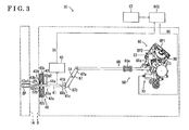
- the door actuating apparatus 20 includes a control portion ECU serving as a control unit including a microcomputer, an operating portion CT operated to open the door 10, the latch mechanism 30 serving as an engagement mechanism retaining the door 10 in a closed state, a door check mechanism 40 retaining the door 10 at a predetermined rotational position, and a driving portion 50 actuating the door 10.
- the door check mechanism 40 and the driving portion 50 serve as a door opening mechanism.
- the control portion ECU further includes a power source circuit controlling supply of electric power to an electric motor 71, which will be described later.
- An example of the operating portion CT is a push button type switch and a touch type switch arranged on a portable device or on the door 10.
- An example of the portable device is a key.
- the operating portion CT connects to the control portion ECU so that the control portion ECU detects operation of the operating portion CT.
- a base panel BP retains major components forming the latch mechanism 30 and the driving portion 50.
- the base panel BP is mounted on a retaining member arranged at the rearward end portion inside the door body D.
- the base panel BP includes a first retaining portion BP1 and a second retaining portion BP2.
- Each of the first retaining portion BP1 and the second retaining portion BP2 is formed in substantially a plate form.
- the first retaining portion BP1 is tilted such that an upper end portion of the first retaining portion BP1 is positioned at a position in a frontward direction relative to a lower end portion of the first retaining portion BP1.
- the second retaining portion BP2 is arranged to extend in a frontward-downward direction at an end portion of the first retaining portion BP1 in a vehicle interior direction.
- a striker receiving recess CP is formed by cutting out a portion of the base panel BP, the portion spanning from a rearward end portion of the first retaining portion BP1 to an end portion of the second retaining portion BP2 in the vehicle interior direction.
- the striker 17 enters inside the door body D through the opening 18 and enters inside the striker receiving recess CP.
- the latch mechanism 30 includes a pole 31 and the latch 32.
- the pole 31 is pivotally supported by the first retaining portion BP1 to be rotatable at a position in an upward direction in Fig. 5 relative to the striker receiving recess CP.
- the pole 31 includes a latch locking portion 31 b extending toward right in Fig. 5 from a rotational shaft 31 a of the pole 31 and a stopper portion 31 c extending toward left in Fig. 5 from the rotational shaft 31 a.
- a torsion coil spring is arranged between the pole 31 and the first retaining portion BP1. The torsion coil spring biases the pole 31 in a clockwise direction in Fig. 5 , which is a restraining direction of the pole 31.
- the pole 31 is positioned at a lock position when the stopper portion 31 c makes contact with the first retaining portion BP1.
- the stopper portion 31 c is formed with a portion to be pushed downward 31c1, which serves as an engaging portion.
- the portion to be pushed downward 31c1 is formed by folding an end portion of the stopper portion 31 c in Fig. 5 toward a surface where Fig. 5 is drawn.
- the portion to be pushed downward 31 c1 is positioned at a position in a downward direction relative to a pushing down portion 63a1, as Fig. 4 illustrates, so that the portion to be pushed downward 31c1 may be pushed downward by the pushing down portion 63a1 of an open lever 63, which will be described later.
- the latch 32 is pivotally supported by the first retaining portion BP1 to be rotatable at a position in a downward direction in Fig. 5 relative to the striker receiving recess CP.
- the latch 32 includes a half-latch projection 32b and a full-latch projection 32c, each of which projects radially outward from a rotational shaft 32a of the latch 32.
- the half-latch projection 32b and the full-latch projection 32c extend substantially parallel to each other in a same direction.
- a recess 32d is formed between the half-latch projection 32b and the full-latch projection 32c.
- a torsion coil spring is arranged between the latch 32 and the first retaining portion BP1 to bias the latch 32 in a counterclockwise direction in Fig.
- a stopper formed on the latch 32 is in contact with the first retaining portion BP1 so that the latch 32 is positioned at a predetermined position, which is an unlatch position of the latch 32, shown in Fig. 5 .
- the striker 17 enters the striker receiving recess CP. In addition, the striker 17 enters inside the recess 32d formed on the latch 32. When the striker 17 makes contact with a side wall of the recess 32d, the striker 17 pushes the latch 32 and the latch 32 rotates in the clockwise direction in Fig. 5 , which is a restraining direction of the latch 32.
- a rotational position of the latch 32 moves from the unlatch position of the latch 32 shown in Fig. 5 to a rotational position shown in Fig. 7 , which is a full-latch position, via a rotational position shown in Fig. 6 , which is a half-latch position.
- the full-latch projection 32c of the latch 32 engages with the latch locking portion 31 b of the pole 31 to restrain the latch 32 from rotating in the release direction of the latch 32 and to retain a state where the latch 32 retains the striker 17.
- the door 10 is retained at a full close position and a full close state is retained.
- the latch mechanism 30 includes a latch position detector detecting the rotational position of the latch 32.
- the latch position detector connects to the control portion ECU.
- the latch position detector sends detected results to the control portion ECU and the control portion ECU receives detected results as inputs.
- the latch 32 rotates in the release direction of the latch 32 biased by the torsion coil spring and shifts to the state illustrated in Fig. 5 .
- the door 10 is released from a state where the latch 32 retains the door 10.
- the door 10 may be opened in this state.
- a protruding portion 32c1 is formed to protrude radially outward.
- the protruding portion 32c1 makes contact with a see-saw type lever 62, which will be described later, in a state where the rotational position of the latch 32 is at the half-latch position.
- the latch 32 rotates so that the rotational position of the latch 32 shifts from the half-latch position to the full-latch position.
- a retained state of the door 10 shifts from the half-latch state to the full close state.
- the door check mechanism 40 includes, a rod 41, which serves as an engagement member, and a holding mechanism 42, which serves as a retaining mechanism.
- the door 10 supports the rod 41 such that the rod 41 advances and retracts relative to the door 10.
- the holding mechanism 42 retains the rod 41 at a predetermined position.
- the rod 41 is formed in an elongated form. A cross sectional shape of the rod 41 taken in a direction perpendicular to a longitudinal direction of the rod 41 is substantially a rectangle.
- a pair of recessed portions 41 a recessing in the direction perpendicular to the longitudinal direction of the rod 41 are formed on an upward surface and a downward surface of the rod 41 at a portion positioned closer to a first end of the rod 41 in the longitudinal direction relative to the middle portion of the rod 41 in the longitudinal direction. Furthermore, a pair of recessed portions 41 b recessing in the direction perpendicular to the longitudinal direction of the rod 41 are formed on the upward surface and the downward surface of the rod 41 at the first end of the rod 41 in the longitudinal direction.
- the first end of the rod 41 is inserted into the inside of the door 10 from an opening 19 provided at a frontward end portion of the door 10.
- the holding mechanism 42 is arranged inside of the door body D.
- the holding mechanism 42 retains the rod 41 by sandwiching the rod 41 from upward and from downward.
- the holding mechanism 42 includes a housing 42a mounted inside of the door 10 at the frontward end portion of the door 10.
- the housing 42a is formed in a box form.
- the housing 42a is provided with an opening portion 42a1 on a surface of the housing 42a facing the opening 19 of the door 10.
- the housing 42a further includes an opening portion 42a2 on a surface of the housing 42a facing opposite direction relative to the opening 19 of the door 10.
- the first end of the rod 41 in the longitudinal direction which is inserted into the inside of the door 10 from the opening 19, is inserted into inside of the housing 42a from the opening portion 42a1 and projects outside the housing 42a, which is inside of the door body D, through an opening portion 42a2.
- a stopper 41 c which is an engagement portion, is mounted on the first end of the rod 41 in the longitudinal direction.
- the stopper 41 c protrudes outward, which is a direction perpendicular to the longitudinal direction, from a peripheral portion of the first end of the rod 41 in the longitudinal direction.
- the stopper 41 c makes contact with the housing 42a when the rod 41 moves frontward relative to the door 10 and restrains movement of the rod 41 in the frontward direction relative to the door 10.
- a second end of the rod 41 in the longitudinal direction is rotatably supported by a supporting member SP mounted on the frontward pillar 14.
- a pair of pushing members 42b facing each other are arranged inside the housing 42a.
- the pair of pushing members 42b sandwich the rod 41 from the upward and from the downward.
- Springs 42c retained on the housing 42a bias the pushing members 42b toward the rod 41.
- Each of the pushing members 42b includes a roller member 42b1 at an end portion that makes contact with the rod 41.
- the roller members 42b1 roll on an upward surface and a downward surface of the rod 41.
- the door check mechanism 40 includes a door open/close sensor 43 detecting an open/close state of the door 10 by detecting a position of the rod 41 relative to the door body D.
- An example of the door open/close sensor 43 is a sensor formed by a multiple number of switches switching between ON/OFF states by a small projections formed on the rod 41 pushing the switches.
- Another example of the door open/close sensor 43 is a sensor optically measuring a distance between the sensor and a rearward end surface of the rod 41.
- the rod 41 advances and retracts relative to the door 10.
- the rod 41 moves frontward relative to the door body D and the pair of pushing members 42b fit to a pair of recessed portions 41 a.
- the position at a time at which the door is in the slightly opened state is referred to as a door opening ready position, which serves as a predetermined rotational position.
- the pair of pushing members 42b fit to the pair of recessed portions 41 b.
- the door 10 is retained at a full open position.
- the stopper 41 c makes contact with the housing 42a at this time. As a result, the door 10 is restrained from rotating further in the vehicle exterior direction.
- the driving portion 50 includes a lever mechanism 60 and a drive mechanism 70, which serves as an actuator.
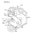
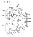
- the lever mechanism 60 includes an active lever 61, which serves as a first driven member, the see-saw type lever 62, the open lever 63, which serves as a second driven member, a cam type lever 64, a relay lever 65, a rod 66, and a release lever 67, which serves as a third driven member.
- Direction of a rotational axis for each lever of the lever mechanism 60 is the same. The direction of the rotational axis for each lever is perpendicular to direction of the rotational axis for the pole 31 and the latch 32 retained on the first retaining portion BP1.
- the active lever 61 is formed in substantially a sector form.
- the second retaining portion BP2 pivotally supports the active lever 61 to be rotatable about an axis C1, which is the center of an arc of the sector form.
- a gear portion 61 a is formed at an outer periphery of a curved side of the active lever 61.
- the active lever 61 includes a protruding retaining portion 61 b extending rightward in Fig. 4 from the axis C1.
- the protruding retaining portion 61 b pivotally supports the see-saw type lever 62, which will be described later, to be rotatable at the protruding retaining portion 61b.
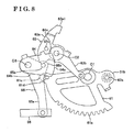
- a contact portion 61 c is formed as Fig. 8 illustrates.
- the contact portion 61 c is configured to engage with the relay lever 65, which will be described later, in a state where the active lever 61 rotates in a clockwise direction in Fig. 4 .
- a contact pin 61 d in Fig. 4 is formed to protrude in a direction toward the surface where Fig. 4 is drawn.
- the contact pin 61 d is configured to engage with the cam type lever 64, which will be described later, in a state where the active lever 61 rotates in the clockwise direction in Fig. 4 with the axis C1 as a center of rotation.
- the see-saw type lever 62 includes a first arm 62b and a second arm 62c.
- the first arm 62b extends from a rotational shaft 62a in one direction of the see-saw type lever 62.
- the second arm 62c extends from the rotational shaft 62a in an opposite direction relative to the direction the first arm 62b extends.
- the first arm 62b and the second arm 62c are arranged in a see-saw state with the rotational shaft 62a that is positioned between the first arm 62b and the second arm 62c.
- the first arm 62b is arranged at a position where an end portion of the first arm 62b may contact with the protruding portion 32c1 of the latch 32.
- a contact roller 62d is attached to an end portion of the second arm 62c.
- a torsion coil biases the see-saw type lever 62 in a direction that makes the end portion of the first arm 62b move away from the protruding portion 32c1 of the latch 32.
- the second retaining portion BP2 pivotally supports the open lever 63 to be rotatable about an axis C2.
- the open lever 63 is arranged at a position in a direction opposite to where the second retaining portion BP2 is arranged relative to the active lever 61. In other words, relative to the active lever 61 in Fig. 4 , the open lever 63 is positioned in a direction toward the surface where Fig. 4 is drawn.
- the open lever 63 includes a pole driving portion 63a and a positioning portion 63b.
- the pole driving portion 63a extends leftward in Fig. 4 from the axis C2 and further extends obliquely upward toward right in Fig. 4 .
- the positioning portion 63b extends obliquely downward toward right in Fig. 4 from the axis C2.
- the pushing down portion 63a1 is arranged at an end portion of the pole driving portion 63a.
- the pushing down portion 63a1 pushes the portion to be pushed downward 31 c1 of the pole 31 downward.
- a contact pin 63c is formed at a base portion of the pole driving portion 63a of the open lever 63.
- the contact pin 63c protrudes in a direction opposite to where the second retaining portion BP2 is arranged in Fig. 4 , which is a direction toward the surface where Fig. 4 is drawn.
- the contact pin 63c is arranged at a position at which the contact pin 63c may contact with the cam type lever 64, which will be described later. Note that, a torsion spring is attached to the open lever 63 so that the open lever 63 is biased in a counterclockwise direction in Fig. 4 .
- the contact roller 62d is in contact with a downward end of the positioning portion 63b of the open lever 63 so that the contact roller 62d is positioned at a predetermined position.
- the positioning portion 63b of the open lever 63 detaches from the contact roller 62d. This process will be described in more detail later.
- the see-saw type lever 62 is released from the predetermined position, which is the position retained by the open lever 63, so that the see-saw type lever 62 is allowed to rotate relative to the active lever 61.
- the second retaining portion BP2 pivotally supports the cam type lever 64 and the relay lever 65 to be rotatable at an axis C3, which is a position distanced from the axis C2 of the open lever 63 at a position obliquely downward toward left in Fig. 4 .
- the cam type lever 64 is arranged at a position in the direction opposite to where the second retaining portion BP2 is arranged relative to the open lever 63.
- the cam type lever 64 in Fig. 4 is arranged at a position in a direction toward the surface where Fig. 4 is drawn relative to the open lever 63.
- the cam type lever 64 is formed in substantially a sector form.
- the cam type lever 64 includes an arc surface portion 64a formed in a circularly curved surface form and flat surface portions 64b, 64c formed in a flat surface form extending toward the axis C3 from each end of the arc surface portion 64a, the end in a circumferential direction.
- a torsion spring is attached to the cam type lever 64 to bias the cam type lever 64 in the clockwise direction in Fig. 4 .
- the relay lever 65 is arranged at a position in a direction opposite to where the second retaining portion BP2 is arranged relative to the active lever 61, which is a position in a direction of the second retaining portion BP2 relative to the open lever 63. In other words, the relay lever 65 is arranged between the active lever 61 and the open lever 63.
- the relay lever 65 includes a connecting portion 65a extending obliquely downward toward right in Fig. 4 from the axis C3 of the relay lever 65 and a protruding portion 65b protruding obliquely upward toward right in Fig. 8 from the axis C3 of the relay lever 65, as Fig. 8 illustrates.
- a contact pin 65c is formed to protrude in a direction toward the second retaining portion BP2 from a central portion of the protruding portion 65b. In a state where the door 10 is at the full close position, the contact pin 65c is positioned at a position in an upward direction in Fig. 4 relative to the contact portion 61 c of the active lever 61.
- the rod 66 is arranged to extend in a vehicle frontward-rearward direction, as Fig. 3 illustrates.
- a rearward end of the rod 66 is mounted on an end portion of the connecting portion 65a of the relay lever 65.
- a frontward end of the rod 66 is linked to the release lever 67, which will be described later.
- the rod 66 includes a coil spring 66a serving as a limiter mechanism at an intermediate position of the rod 66.
- the coil spring 66a and the rod 66 share an axis in a straight line.
- the release lever 67 is pivotally supported at an axis C4 to be rotatable about the axis C4.
- the axis C4 is at a position distanced obliquely downward toward left in Fig. 3 from the axis C3 of the cam type lever 64 and the relay lever 65 and distanced obliquely upward toward right in Fig. 3 from a rearward end of the rod 41 of the door check mechanism 40.
- the release lever 67 includes a link portion 67a and a pushing portion 67b.
- the link portion 67a extends obliquely upward toward right in Fig. 3 from the axis C4.
- the pushing portion 67b extends from the axis C4 in a direction opposite to the direction the link portion 67a extends. In a state where the door 10 is at the full close position, the pushing portion 67b is in contact with the rearward end of the rod 41.
- the release lever 67 rotates in a clockwise direction in Fig. 3 with the axis C4 as the center of rotation in a state where the rod 66 moves in a rearward direction. As a result, the pushing portion 67b pushes a rearward end surface of the rod 41 frontward.
- the drive mechanism 70 includes the electric motor 71.
- the electric motor 71 is fixed at an appropriately selected position on the second retaining portion BP2.
- An output shaft of the electric motor 71 connects to the gear portion 61 a formed at the outer peripheral end of the active lever 61 via a reducer 72 formed by a multiple number of gears.
- the control portion ECU sends a drive signal DS, which is a signal to rotate the electric motor 71 in a positive direction, to the electric motor 71 when the control portion ECU detects a state where the operating portion CT is operated while the door 10 is at the full close position.
- a rotational position of the output shaft of the electric motor 71 or the rotational position of the gears forming the reducer 72 during a period during which the door 10 is at the full close position is referred to as an initial position.
- a rotation number or a rotational angle from the initial position of the electric motor 71 or the gears forming the reducer 72 is referred to as an actuated position of the drive mechanism 70, which serves as an actuated position of the actuator.
- the contact portion 61 c of the active lever 61 is at a position in a downward direction relative to the contact pin 65c of the relay lever 65. Accordingly, the contact portion 61 c and the contact pin 65c are not engaged with each other.
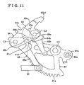
- the cam type lever 64 rotates in a counterclockwise direction in Fig. 8 with the axis C3 as the center of rotation. Accordingly, the flat surface portion 64c of the cam type lever 64 makes contact with the contact pin 63c of the open lever 63, as Fig. 9 illustrates.
- An actuated position of the drive mechanism 70 in this state is referred to as a first position in the door actuating apparatus 20 according to this disclosure.
- the cam type lever 64 further rotates in a counterclockwise direction in Fig. 9 with the axis C3 as the center of rotation
- the flat surface portion 64c pushes the contact pin 63c, which in turn makes the open lever 63 rotates in a clockwise direction in Fig. 9 with the axis C2 as the center of rotation, so that the pushing down portion 63a1 arranged on the pole driving portion 63a of the open lever 63 pushes the portion to be pushed downward 31c1 of the pole 31 downward, as Fig. 4 illustrates.
- An actuated position of the drive mechanism 70 in a state where the portion to be pushed downward 31c1 is completely pushed downward is referred to as a second position in the door actuating apparatus 20 according to this disclosure.
- a contact point between the contact pin 63c and the flat surface portion 64c moves from a direction of the axis C3 toward the arc surface portion 64a.
- the positioning portion 63b of the open lever 63 is positioned at a position distanced from the contact roller 62d. Accordingly, the see-saw type lever 62 is released from being retained at the predetermined position by the open lever 63 and rotation of the see-saw type lever 62 relative to the active lever 61 is allowed.
- the see-saw type lever 62 is biased by the torsion coil spring so that an end portion of the first arm 62b detaches from the protruding portion 32c1 of the latch 32. Accordingly, the latch 32 rotates in the release direction of the latch 32 to release the door 10 from being retained at the full close position.
- the cam type lever 64 rotates in the counterclockwise direction in Fig. 9 with the axis C3 as the center of rotation as a result of the active lever 61 further rotating in the clockwise direction in Fig. 9 with the axis C1 as the center of rotation. Accordingly, a state of the contact pin 63c of the open lever 63 shifts from a state in which the contact pin 63c is in contact with the flat surface portion 64c to a state in which the contact pin 63c is in contact with the arc surface portion 64a, as Fig. 10 illustrates. Accordingly, the open lever 63 is restrained from further rotating even in a state where the cam type lever 64 further rotates. As a result, a state in which the pushing down portion 63a1 pushing down the portion to be pushed downward 31c1 is retained.
- the door 10 is retained at the door opening ready position. More specifically, in a state where an external force to rotate the door 10 is exerted on the door 10, the rod 41 is biased to return to the position corresponding to the door opening ready position by the pushing members 42b of the holding mechanism 42, which serves as a biasing mechanism. Note that, the door 10 may rotate toward the full close position or toward the full open position in a case where the external force is large enough to make the pushing members 42b detach from the recessed portions 41 a. Operation of the door actuating apparatus 20 according to the embodiment in a case in which a large external force is exerted on the door 10 will be described later.
- An actuated position of the drive mechanism 70 in a state where the door 10 is retained at the door opening ready position is referred to as a fourth position in the door actuating apparatus according to this disclosure.
- the rearward end of the rod 41 is at a position detached from the pushing portion 67b of the release lever 67.
- the door open/close sensor 43 transmits a door open signal OS, which indicates that the door 10 is opened, to the control portion ECU.
- the control portion ECU receives the door open signal OS, the control portion ECU sends a drive signal DS, which is a signal commanding the electric motor 71 to rotate in a negative direction, to the electric motor 71 to rotate the electric motor 71 in the negative direction.
- each of the release lever 67, the cam type lever 64, and the open lever 63 rotates in an opposite direction in a reversed order compared to when the door 10 is actuated, or driven, to open so that the open lever 63 and the release lever 67 returns to positions illustrated in Figs. 3 and 4 .
- a state of each of the release lever 67, the cam type lever 64, and the open lever 63 shifts to the state in which a user may close the door 10.
- the pushing down portion 63a1 arranged on the pole driving portion 63a of the open lever 63 detaches from the portion to be pushed downward 31c1 of the pole 31 so that the pole 31 returns to a position illustrated in Fig. 5 biased by the torsion coil spring. In other words, the pole 31 shifts to a state engageable with the latch 32.
- the rod 41 moves rearward. Accordingly, the rod 41 pushes the pushing portion 67b of the release lever 67 so that the release lever 67 rotates in the counterclockwise direction in Fig. 3 with the axis C4 as the center of rotation.
- the rearward end of the rod 66 is connected to the connecting portion 65a of the relay lever 65.
- the relay lever 65 is restrained from rotating by the active lever 61. Accordingly, in this case, the rod 66 is exerted with the external force that expands the rod 66 in the axial direction.
- the coil spring 66a is expanded and portion of the rod 66 positioned frontward relative to the coil spring 66a exclusively moves frontward.
- the coil spring 66a returns to an original length, which is a natural length of the coil spring 66a.
- the portion of the rod 66 positioned frontward relative to the coil spring 66a and the release lever 67 return to original positions. As a result, the door 10 return to the door opening ready position.
- the control portion ECU In a state where the control portion ECU detects that a state of the door 10 is in a half-latch state, the control portion ECU sends a driving signal DS, which is a signal commanding the electric motor 71 to rotate in a negative direction, to the electric motor 71.
- a driving signal DS which is a signal commanding the electric motor 71 to rotate in a negative direction
- the active lever 61 rotates in the counterclockwise direction in Fig. 4 with the axis C1 as the center of rotation.
- the contact roller 62d is in contact with a downward end portion of the positioning portion 63b of the open lever 63 to retain the contact roller 62d at the predetermined position. Accordingly, in a state where the active lever 61 rotates from a position illustrated in Fig.
- the first arm 62b makes contact with the protruding portion 32c1 of the latch 32 so that the protruding portion 32c1 is pushed upward.
- the latch 32 rotates to shift the rotational position of the latch 32 from the half-latch position to the full-latch position so that the retained state of the door 10 shifts from the half-latch state to the full close state.
- the driving portion 50 is driven and the door 10 is released from being retained. Furthermore, the door 10 is actuated to automatically open to the door opening ready position. As a result, an operational force at a beginning of opening the door 10 is light.
- the door 10 may be released from being retained and the door 10 may be opened to the door opening ready position. Accordingly, a configuration of the control portion ECU of the door actuating apparatus 20 may be simplified, reduced in size, and cost of the door actuating apparatus 20 may be reduced.
- the door 10 is manually rotated from the door opening ready position to the full open position. Nevertheless, the operational force to rotate the door 10 from the door opening ready position to the full open position is considerably small. Accordingly, in a state where the door 10 is arranged to automatically open from the full close position to the door opening ready position similarly to the door actuating apparatus 20 according to the embodiment, an ease of operation is greatly enhanced compared to a door provide without the door actuating apparatus 20 according to the embodiment. In addition, during a period during which the door 10 is actuated by the electric motor 71 from the full close position to the door opening ready position, a state of the door 10 is retained in the disengaged state.
- the door 10 may be manually rotated at any time during a period during which the door 10 is making rotational movement from the full close position to the door opening ready position, without waiting for the door to reach the door opening ready position. Furthermore, when the operating portion CT is operated in a state where the door 10 is at the full close position, the door 10 opens and then the door 10 is retained at the door opening ready position by the door check mechanism 40. Accordingly, the door 10 is restrained from hitting an obstacle positioned at a position in the vehicle exterior direction when the door 10 opens by an unintentionally large amount by inertia at a time at which the door 10 is operated to open.
- the coil spring 66a expands and the portion of the rod 66 in the frontward direction relative to the coil spring 66a exclusively moves frontward. Accordingly, for example, the rod 41, the rod 66 and various levers are restrained from being damaged.
- the door actuating apparatus 20 is not limited to the embodiment described herewith and may be modified or enhanced in following manners.
- the relay lever 65 is configured to rotate after the open lever 63 rotates, however, the open lever 63 and the relay lever 65 may start rotating at the same time.
- a clearance may be defined between the release lever 67 and the rod 41 in a state where the door 10 is at the full close position. Accordingly, the release lever 67 makes contact with the rearward end of the rod 41 when the relay lever 65 reaches the predetermined rotational position after the relay lever 65 starts rotating.
- the door 10 starts opening after the door 10 is released from being retained by the latch mechanism 30.
- the release lever 67 may be used as a trigger to bias the rod 41 frontward.
- a biasing member for example, a spring, biasing the rod 41 frontward and a stopper to lock the rod 41 against a biasing force of the biasing member may be separately provided.
- the release lever 67 may be arranged to contact with the stopper to release the rod 41 from being retained by the stopper so that the rod 41 receives the biasing force of the biasing member.
- the door 10 in the door actuating apparatus 20 is retained at the door opening ready position and at the full open position by the holding mechanism 42 of the door check mechanism 40.
- additional recessed portions similar to the recessed portions 41 a may be formed on the upward surface and the downward surface of the rod 41 to retain the door 10 at additional rotational positions.
- the door check mechanism 40 may be provided with a holding mechanism that may retain the door 10 at a selected rotational position.
- a door actuating apparatus (20) includes an engagement mechanism (30) retaining a door (10) at a full close position, an operating portion (CT) outputting a signal to open the door (10), a control unit (ECU) actuating an actuator (70) in response to receiving the signal, an engagement member (41) advancing and retracting relative to the door (10) in accordance with rotation of the door (10), and a door opening mechanism (40, 50) operating by actuation of the actuator (70), positioning the door (10) at a full close position to a predetermined rotational position by rotating the door (10) in a vehicle exterior direction by biasing the engagement member (41) by engaging with the engagement member (41) when the door (10) is released from an engaged state by the door opening mechanism (40, 50) engaging with the engagement mechanism (30), and releasing engagement with the engagement member (41) in a state where an external force rotating the door (10) in the vehicle exterior direction is exerted on the door (10) at the predetermined rotational position.
Landscapes
- Engineering & Computer Science (AREA)
- Mechanical Engineering (AREA)
- Power-Operated Mechanisms For Wings (AREA)
- Lock And Its Accessories (AREA)
Abstract
Description
- This disclosure generally relates to a door actuating apparatus.
- In general, a vehicle includes a latch apparatus that retains a door at a full close position. A door handle arranged on a door connects to the latch apparatus. In order to open the door that is at the full close position, the door handle is held and pulled strongly to release the door from being retained at the full close position by the latch apparatus. More specifically, a particularly large operational force is required in the beginning at a time of opening the door.
- A vehicle including a door actuating apparatus for automatically opening and closing a door that is rotatably supported by a vehicle body is disclosed in
JP2005-232752A Reference 1. The door actuating apparatus disclosed inReference 1 includes a rod formed in an elongated form and a driving mechanism driving the rod. One end of the rod is retained by the vehicle body to be rotatable. The other end of the rod is retained by a retaining member arranged inside the door such that the rod is configured to advance and retract relative to the door. The driving mechanism is mounted inside the door. The driving mechanism includes an electric motor and a power transmission mechanism. The power transmission mechanism converts rotational movement of the electric motor into linear movement and transmits power from the electric motor to the rod. The power transmission mechanism includes, for example, a worm gear mounted on a driving shaft of the electric motor, a worm wheel meshing with the worm gear, a reducer formed by a multiple number of gears rotating in accordance with rotation of the worm wheel, and a rack gear meshing with one of a multiple number of gears forming the reducer. The other end of the rod is mounted on the rack gear. In addition, an electromagnetic clutch is arranged between the worm wheel and the reducer. A switch for operating the door to open and to close is provided on a portable device or a on a vehicle. The electric motor is actuated when the switch is operated. When the electric motor is actuated in a state where the electromagnetic clutch is connected, driving power of the electric motor is transmitted to the rod. As a result, the door automatically rotates between a full close position and a full open position. In a state where the electromagnetic clutch is connected and the electric motor is not actuated, the door does not move. More specifically, the door is restrained from rotating from a stopped position because the worm gear restrains rotation of the worm wheel. Accordingly, a user may not be able to manually open and close the door. In a state where the electromagnetic clutch is disconnected, rotations of the gears forming the reducer are not transmitted to the worm wheel so that the user may manually open and close the door. Accordingly, the door actuating apparatus according toReference 1 may open and close the door without difficulty by a simple operation of an operation button. In addition, the door may be manually opened and closed by setting the electromagnetic clutch in a disconnected state. - Nevertheless, the door actuating apparatus according to
Reference 1 requires actuation of the electric motor in addition to actuation of the electromagnetic clutch. Accordingly, a drive circuit, for example, a power source circuit, for actuating each of the electric motor and the electromagnetic clutch becomes large in size. In addition, each of the electromagnetic clutch and the electric motor requires separate control. Computer hardware and software configurations of a control apparatus become complex in order to control each of the electromagnetic clutch and the electric motor. Accordingly, a large number of components may be required and cost may increase. - A need thus exists for a door actuating apparatus for reducing an operational force at a time at which a user opens a door that is rotatably supported by a vehicle. In addition, a need exists for the door actuating apparatus that is small in size and low at cost.
- A door actuating apparatus includes an engagement mechanism selectively achieving an engaged state and a disengaged state where the engaged state is a state where a door that is rotatably supported by a vehicle body is retained at a full close position and the disengaged state is a state where the door is not retained at the full close position, an operating portion being operated for rotating the door that is at the full close position outward relative to a vehicle interior, the operating portion outputting a signal to rotate the door, a control unit configured to receive the signal from the operating portion, the control unit actuating an actuator in response to the signal, an engagement member configured to be retained by the vehicle body and engaged with the door, the engagement member advancing and retracting relative to the door in accordance with rotation of the door, and a door opening mechanism operating by actuation of the actuator, the door opening mechanism shifting a state of the engagement mechanism from the engaged state to the disengaged state by engaging with the engagement mechanism that is in the engaged state, the door opening mechanism rotating the door from the full close position to a predetermined rotational position positioned between the full close position and a full open position by engaging with the engagement member, the door opening mechanism allowing the door to rotate in a vehicle exterior direction relative to a rotational position of the door corresponding to an operational position of the door opening mechanism by the door opening mechanism separating from the engagement member in a state where an external force rotating the door in the vehicle exterior direction is exerted on the door in a case where the engagement mechanism is in the disengaged state.
- Upon the arrangement described herewith, the door opening mechanism releases the door from being retained when the operating portion, for example, a switch arranged on a portable device or on a vehicle, is operated to operate the door at the full close position. In other words, a state of the engagement mechanism switches from the engaged state to the disengaged state. At the same time, the actuator actuates the door and the door automatically opens to the predetermined rotational position. As a result, an operational force at a beginning of opening the door is small. In addition, without providing the actuator in multiple numbers, the door may be released from being retained and the door may be opened to the predetermined rotational position. Accordingly, a drive circuit and the control unit of the door actuating apparatus may be simplified, reduced in size, and cost of the door actuating apparatus may be reduced. The door is manually rotated from the predetermined rotational position to the full open position. Nevertheless, the operational force to rotate the door from the predetermined rotational position to the full open position is considerably small. Accordingly, in a state where the door is arranged to automatically open from the full close position to the predetermined rotational position, an ease of operation is greatly enhanced compared to a door provided without the door actuating apparatus according to this disclosure. In addition, during a period during which the door is actuated by the actuator from the full close position to the predetermined rotational position, a state of the engagement mechanism is retained in the disengaged state. As a result, the door may be manually rotated at any time during a period during which the door is making rotational movement from the full close position to the predetermined rotational position, without waiting for the door to reach the predetermined rotational position.
- According to another aspect of this disclosure, the door opening mechanism of the door actuating apparatus rotates the door from the full close position to the predetermined rotational position by engaging with the engagement member after the door opening mechanism shifts the state of the engagement mechanism from the engaged state to the disengaged state by engaging with the engagement mechanism in the engaged state.
- Upon the arrangement described herewith, the door opening mechanism releases the door from being retained when the operating portion, for example, a switch arranged on a portable device or on a vehicle, is operated to operate the door at the full close position. In other words, a state of the engagement mechanism switches from the engaged state to the disengaged state. At the same time, the actuator actuates the door and the door automatically opens to the predetermined rotational position. As a result, an operational force at a beginning of opening the door is small. In addition, without providing the actuator in multiple numbers, the door may be released from being retained and the door may be opened to the predetermined rotational position. Accordingly, a drive circuit and the control unit of the door actuating apparatus may be simplified, reduced in size, and cost of the door actuating apparatus may be reduced. The door is manually rotated from the predetermined rotational position to the full open position. Nevertheless, the operational force to rotate the door from the predetermined rotational position to the full open position is considerably small. Accordingly, in a state where the door is arranged to automatically open from the full close position to the predetermined rotational position, an ease of operation is greatly enhanced compared to a door provided without the door actuating apparatus according to this disclosure. In addition, during a period during which the door is actuated by the actuator from the full close position to the predetermined rotational position, a state of the engagement mechanism is retained in the disengaged state. As a result, the door may be manually rotated at any time during a period during which the door is making rotational movement from the full close position to the predetermined rotational position, without waiting for the door to reach the predetermined rotational position.
- According to further aspect of this disclosure, the door opening mechanism of the door actuating apparatus includes a first driven member moving in accordance with an actuated position of the actuator, a second driven member driven by the first driven member, the second driven member engaging with the engagement mechanism, and a third driven member driven by the first driven member, the third driven member engaging with the engagement member. The door opening mechanism, in a process where the actuated position of the actuator shifts in one direction from a position corresponding to the full close position of the door, shifts the state of the engagement mechanism in the engaged state to the disengaged state by the second driven member pushing an engaging portion of the engagement mechanism in a state where the actuated position of the actuator shifts from a first position to a second position positioned at a position in the aforementioned one direction relative to the first position, moves position of the engagement member relative to the door from a position corresponding to the full close position of the door to a position corresponding to the predetermined rotational position by the third driven member pushing an engagement portion of the engagement member in a state where the actuated position of the actuator is at the second position or in a state where the actuated position of the actuator shifts from a third position positioned at a position in the aforementioned one direction relative to the second position to a fourth position positioned at a position in the aforementioned one direction relative to the third position, retains a state of the engagement mechanism in the disengaged state in a state where the actuated position of the actuator is at a position in the aforementioned one direction relative to the second position, and allows the door to rotate in the vehicle exterior direction relative to the rotational position of the door corresponding to the actuated position of the actuator by the engagement portion of the engagement member separating from the third driven member in a state where the external force rotating the door in the vehicle exterior direction is exerted on the door in a case where the engagement mechanism is in the disengaged state.
- Upon the arrangement described herewith, the door opening mechanism releases the door from being retained when the operating portion, for example, a switch arranged on a portable device or on a vehicle, is operated to operate the door at the full close position. In other words, a state of the engagement mechanism switches from the engaged state to the disengaged state. At the same time, the actuator actuates the door and the door automatically opens to the predetermined rotational position. As a result, an operational force at a beginning of opening the door is small. In addition, without providing the actuator in multiple numbers, the door may be released from being retained and the
door 10 may be opened to the predetermined rotational position. Accordingly, a drive circuit and the control unit of the door actuating apparatus may be simplified, reduced in size, and cost of the door actuating apparatus may be reduced. The door is manually rotated from the predetermined rotational position to the full open position. Nevertheless, the operational force to rotate the door from the predetermined rotational position to the full open position is considerably small. Accordingly, in a state where the door is arranged to automatically open from the full close position to the predetermined rotational position, an ease of operation is greatly enhanced compared to a door provided without the door actuating apparatus according to this disclosure. In addition, during a period during which the door is actuated by the actuator from the full close position to the predetermined rotational position, a state of the engagement mechanism is retained in the disengaged state. As a result, the door may be manually rotated at any time during a period during which the door is making rotational movement from the full close position to the predetermined rotational position, without waiting for the door to reach the predetermined rotational position. - According to another aspect of this disclosure, the door actuating apparatus further includes a limiter mechanism blocking a force in accordance with an external force from the engagement member to the door opening mechanism in a state where an external force rotating the door in a vehicle interior direction is exerted on the door in a case where the engagement mechanism is in the disengaged state.
- Accordingly, the door opening mechanism is restrained from being damaged at a time at which the external force is transmitted to components forming the door opening mechanism.
- According to further aspect of this disclosure, the door actuating apparatus further includes a retaining mechanism retaining the engagement member on the door at the position corresponding to the predetermined rotational position of the door.
- Upon the arrangement described herewith, when the operating portion is operated to operate the door positioned at the full close position, the door opens to the predetermined rotational position and retained at the predetermined rotational position. Accordingly, the door is restrained from hitting an obstacle positioned at a position in the vehicle exterior direction when the door opens by an unintentionally large amount by inertia at a time at which the door is operated to open.
- According to another aspect of this disclosure, the door actuating apparatus further includes a biasing mechanism exerting a force on the engagement member, the force that is in a direction to restore position of the engagement member relative to the door to the position corresponding to the predetermined rotational position of the door, in a state where the engagement member positioned at the position corresponding to the predetermined rotational position of the door is caused to shift the position from the position corresponding to the predetermined rotational position of the door.
- Upon the arrangement described herewith, when the operating portion is operated to operate the door positioned at the full close position, the door opens to the predetermined rotational position and retained at the predetermined rotational position. Accordingly, the door is restrained from hitting an obstacle positioned at a position in the vehicle exterior direction when the door opens by an unintentionally large amount by inertia at a time at which the door is operated to open.
- According to another aspect of this disclosure, the door opening mechanism of the door actuating apparatus pushes an end portion of the engagement member to rotate the door at the full close position to the predetermined rotational position positioned between the full close position and the full open position.
- Upon the arrangement described herewith, the door opening mechanism releases the door from being retained when the operating portion, for example, a switch arranged on a portable device or on a vehicle, is operated to operate the door at the full close position. In other words, a state of the engagement mechanism switches from the engaged state to the disengaged state. At the same time, the actuator actuates the door and the door automatically opens to the predetermined rotational position. As a result, an operational force at a beginning of opening the door is small.
- The foregoing and additional features and characteristics of this disclosure will become more apparent from the following detailed description considered with the reference to the accompanying drawings, wherein:
-
Fig. 1 is a schematic drawing illustrating a door of a vehicle where a door actuating apparatus according to an embodiment is mounted; -
Fig. 2 is a top view drawing illustrating the door inFig. 1 ; -
Fig. 3 is a schematic drawing illustrating the door actuating apparatus inFig. 1 ; -
Fig. 4 is an enlarged view drawing illustrating major parts of a driving portion illustrated inFig. 3 being enlarged; -
Fig. 5 is an enlarged view drawing illustrating a latch mechanism viewed from frontward in a state where the door is released from being retained; -
Fig. 6 is an enlarged view drawing illustrating the latch mechanism viewed from frontward in a state where the door is in a half-latch state; -
Fig. 7 is an enlarged view drawing illustrating the latch mechanism viewed from frontward in a state where the door is in a full close state; -
Fig. 8 is an enlarged view drawing illustrating postures of various levers in a state where a contact pin of an active lever makes contact with a cam type lever; -
Fig. 9 is an enlarged view drawing illustrating postures of various levers in a state where the cam type lever makes contact with a contact pin of an open lever; -
Fig. 10 is an enlarged view drawing illustrating postures of various levers in a state where the active lever makes contact with a relay lever; and -
Fig. 11 is an enlarged view drawing illustrating postures of various levers in a state where the relay lever rotates pushed by the active lever. - A
door actuating apparatus 20 according to an embodiment will be described. First, a structure of adoor 10, which is where thedoor actuating apparatus 20 is to be mounted, will be described. AsFigs. 1 and 2 illustrate, thedoor 10 includes a door body D formed by bonding an outer panel OP arranged at a position in an exterior direction relative to a vehicle interior 11 and an inner panel IP arranged at a position in an interior direction relative to the vehicle interior 11. A void is formed between the outer panel OP and the inner panel IP. Thedoor actuating apparatus 20 is arranged in the void, which is an internal portion of the door body D. Thedoor 10 is mounted on afrontward pillar 14 via ahinge 15. Thefrontward pillar 14 is a structure forming a frontward side surface of adoor opening portion 12. Thedoor opening portion 12 is formed at a side portion of the vehicle interior 11. Thedoor 10 rotates about a rotational axis of thehinge 15 to open and close thedoor opening portion 12. On acenter pillar 16 forming a rearward side surface of thedoor opening portion 12, astriker 17 is mounted. Thestriker 17 engages with alatch 32 forming alatch mechanism 30, which will be described later. Anopening 18 is formed at a rearward end portion of the door body D. In a state where thedoor 10 is operated to close, thestriker 17 enters the door body D through theopening 18. - As
Fig. 3 illustrates, thedoor actuating apparatus 20 includes a control portion ECU serving as a control unit including a microcomputer, an operating portion CT operated to open thedoor 10, thelatch mechanism 30 serving as an engagement mechanism retaining thedoor 10 in a closed state, adoor check mechanism 40 retaining thedoor 10 at a predetermined rotational position, and a drivingportion 50 actuating thedoor 10. Note that, thedoor check mechanism 40 and the drivingportion 50 serve as a door opening mechanism. - The control portion ECU further includes a power source circuit controlling supply of electric power to an
electric motor 71, which will be described later. An example of the operating portion CT is a push button type switch and a touch type switch arranged on a portable device or on thedoor 10. An example of the portable device is a key. The operating portion CT connects to the control portion ECU so that the control portion ECU detects operation of the operating portion CT. - As
Fig. 4 illustrates, a base panel BP retains major components forming thelatch mechanism 30 and the drivingportion 50. The base panel BP is mounted on a retaining member arranged at the rearward end portion inside the door body D. The base panel BP includes a first retaining portion BP1 and a second retaining portion BP2. Each of the first retaining portion BP1 and the second retaining portion BP2 is formed in substantially a plate form. In a state where the base panel BP is mounted on the door body D, the first retaining portion BP1 is tilted such that an upper end portion of the first retaining portion BP1 is positioned at a position in a frontward direction relative to a lower end portion of the first retaining portion BP1. Furthermore, the second retaining portion BP2 is arranged to extend in a frontward-downward direction at an end portion of the first retaining portion BP1 in a vehicle interior direction. On the base panel BP, a striker receiving recess CP is formed by cutting out a portion of the base panel BP, the portion spanning from a rearward end portion of the first retaining portion BP1 to an end portion of the second retaining portion BP2 in the vehicle interior direction. In a state where thedoor 10 is closed, thestriker 17 enters inside the door body D through theopening 18 and enters inside the striker receiving recess CP. - As
Fig. 5 illustrates, thelatch mechanism 30 includes apole 31 and thelatch 32. Thepole 31 is pivotally supported by the first retaining portion BP1 to be rotatable at a position in an upward direction inFig. 5 relative to the striker receiving recess CP. Thepole 31 includes alatch locking portion 31 b extending toward right inFig. 5 from arotational shaft 31 a of thepole 31 and astopper portion 31 c extending toward left inFig. 5 from therotational shaft 31 a. A torsion coil spring is arranged between thepole 31 and the first retaining portion BP1. The torsion coil spring biases thepole 31 in a clockwise direction inFig. 5 , which is a restraining direction of thepole 31. Thepole 31 is positioned at a lock position when thestopper portion 31 c makes contact with the first retaining portion BP1. Thestopper portion 31 c is formed with a portion to be pushed downward 31c1, which serves as an engaging portion. The portion to be pushed downward 31c1 is formed by folding an end portion of thestopper portion 31 c inFig. 5 toward a surface whereFig. 5 is drawn. The portion to be pushed downward 31 c1 is positioned at a position in a downward direction relative to a pushing down portion 63a1, asFig. 4 illustrates, so that the portion to be pushed downward 31c1 may be pushed downward by the pushing down portion 63a1 of anopen lever 63, which will be described later. - The
latch 32 is pivotally supported by the first retaining portion BP1 to be rotatable at a position in a downward direction inFig. 5 relative to the striker receiving recess CP. Thelatch 32 includes a half-latch projection 32b and a full-latch projection 32c, each of which projects radially outward from arotational shaft 32a of thelatch 32. The half-latch projection 32b and the full-latch projection 32c extend substantially parallel to each other in a same direction. Arecess 32d is formed between the half-latch projection 32b and the full-latch projection 32c. A torsion coil spring is arranged between thelatch 32 and the first retaining portion BP1 to bias thelatch 32 in a counterclockwise direction inFig. 5 , which is a release direction of thelatch 32. In a state where thedoor 10 is open, a stopper formed on thelatch 32 is in contact with the first retaining portion BP1 so that thelatch 32 is positioned at a predetermined position, which is an unlatch position of thelatch 32, shown inFig. 5 . - In a case where the
door 10 is closed from a state where thedoor 10 is open, thestriker 17 enters the striker receiving recess CP. In addition, thestriker 17 enters inside therecess 32d formed on thelatch 32. When thestriker 17 makes contact with a side wall of therecess 32d, thestriker 17 pushes thelatch 32 and thelatch 32 rotates in the clockwise direction inFig. 5 , which is a restraining direction of thelatch 32. - A rotational position of the
latch 32 moves from the unlatch position of thelatch 32 shown inFig. 5 to a rotational position shown inFig. 7 , which is a full-latch position, via a rotational position shown inFig. 6 , which is a half-latch position. At the full-latch position illustrated inFig. 7 , the full-latch projection 32c of thelatch 32 engages with thelatch locking portion 31 b of thepole 31 to restrain thelatch 32 from rotating in the release direction of thelatch 32 and to retain a state where thelatch 32 retains thestriker 17. As a result, thedoor 10 is retained at a full close position and a full close state is retained. Note that, in a state where the rotational position of thelatch 32 is at the half-latch position shown inFig. 6 , the half-latch projection 32b of thelatch 32 engages with thelatch locking portion 31 b of thepole 31. The state where thelatch 32 retains thestriker 17 is likewise retained in this state, however, thedoor 10 is retained at a position close to the full close position and the state of thedoor 10 is in a state generally known as a half-latch state. Note that, thelatch mechanism 30 includes a latch position detector detecting the rotational position of thelatch 32. The latch position detector connects to the control portion ECU. The latch position detector sends detected results to the control portion ECU and the control portion ECU receives detected results as inputs. - In a state where the
latch 32 retains thestriker 17, when theopen lever 63 pushes down the portion to be pushed downward 31c1, thepole 31 rotates in a counterclockwise direction inFig. 7 , which is a release direction of thepole 31. Thepole 31 rotates to a rotational position illustrated with a broken line inFig. 7 , which is an unlock position of thepole 31. At the rotational position illustrated with the broken line, thepole 31 and thelatch 32 are not engaged. Accordingly, thelatch 32 is released from a state where thepole 31 restrains rotation of thelatch 32 so that thelatch 32 is allowed to rotate in the release direction of thelatch 32. As a result, thelatch 32 rotates in the release direction of thelatch 32 biased by the torsion coil spring and shifts to the state illustrated inFig. 5 . In other words, thedoor 10 is released from a state where thelatch 32 retains thedoor 10. Thedoor 10 may be opened in this state. - Furthermore, as
Fig. 5 illustrates, at a base portion of the full-latch projection 32c, a protruding portion 32c1 is formed to protrude radially outward. The protruding portion 32c1 makes contact with a see-saw type lever 62, which will be described later, in a state where the rotational position of thelatch 32 is at the half-latch position. In a state where the protruding portion 32c1 is pushed upwardly by the see-saw type lever 62, thelatch 32 rotates so that the rotational position of thelatch 32 shifts from the half-latch position to the full-latch position. As a result, a retained state of thedoor 10 shifts from the half-latch state to the full close state. - The
door check mechanism 40 will be described next. AsFig. 3 illustrates, thedoor check mechanism 40 includes, arod 41, which serves as an engagement member, and a holding mechanism 42, which serves as a retaining mechanism. Thedoor 10 supports therod 41 such that therod 41 advances and retracts relative to thedoor 10. The holding mechanism 42 retains therod 41 at a predetermined position. Therod 41 is formed in an elongated form. A cross sectional shape of therod 41 taken in a direction perpendicular to a longitudinal direction of therod 41 is substantially a rectangle. A pair of recessedportions 41 a recessing in the direction perpendicular to the longitudinal direction of therod 41 are formed on an upward surface and a downward surface of therod 41 at a portion positioned closer to a first end of therod 41 in the longitudinal direction relative to the middle portion of therod 41 in the longitudinal direction. Furthermore, a pair of recessedportions 41 b recessing in the direction perpendicular to the longitudinal direction of therod 41 are formed on the upward surface and the downward surface of therod 41 at the first end of therod 41 in the longitudinal direction. The first end of therod 41 is inserted into the inside of thedoor 10 from anopening 19 provided at a frontward end portion of thedoor 10. - The holding mechanism 42 is arranged inside of the door body D. The holding mechanism 42 retains the
rod 41 by sandwiching therod 41 from upward and from downward. The holding mechanism 42 includes ahousing 42a mounted inside of thedoor 10 at the frontward end portion of thedoor 10. Thehousing 42a is formed in a box form. Thehousing 42a is provided with an opening portion 42a1 on a surface of thehousing 42a facing theopening 19 of thedoor 10. Thehousing 42a further includes an opening portion 42a2 on a surface of thehousing 42a facing opposite direction relative to theopening 19 of thedoor 10. The first end of therod 41 in the longitudinal direction, which is inserted into the inside of thedoor 10 from theopening 19, is inserted into inside of thehousing 42a from the opening portion 42a1 and projects outside thehousing 42a, which is inside of the door body D, through an opening portion 42a2. On therod 41 arranged in this state, astopper 41 c, which is an engagement portion, is mounted on the first end of therod 41 in the longitudinal direction. In a state where thestopper 41 c is mounted on the first end of therod 41 in the longitudinal direction, thestopper 41 c protrudes outward, which is a direction perpendicular to the longitudinal direction, from a peripheral portion of the first end of therod 41 in the longitudinal direction. Thestopper 41 c makes contact with thehousing 42a when therod 41 moves frontward relative to thedoor 10 and restrains movement of therod 41 in the frontward direction relative to thedoor 10. In addition, a second end of therod 41 in the longitudinal direction is rotatably supported by a supporting member SP mounted on thefrontward pillar 14. Inside thehousing 42a, a pair of pushingmembers 42b facing each other are arranged. The pair of pushingmembers 42b sandwich therod 41 from the upward and from the downward. Springs 42c retained on thehousing 42a bias the pushingmembers 42b toward therod 41. Each of the pushingmembers 42b includes a roller member 42b1 at an end portion that makes contact with therod 41. The roller members 42b1 roll on an upward surface and a downward surface of therod 41. - The
door check mechanism 40 includes a door open/close sensor 43 detecting an open/close state of thedoor 10 by detecting a position of therod 41 relative to the door body D. An example of the door open/close sensor 43 is a sensor formed by a multiple number of switches switching between ON/OFF states by a small projections formed on therod 41 pushing the switches. Another example of the door open/close sensor 43 is a sensor optically measuring a distance between the sensor and a rearward end surface of therod 41. - In a state where the
door 10 is opened and closed, therod 41 advances and retracts relative to thedoor 10. In a state where thedoor 10 at the full close position is rotated in a vehicle exterior direction, therod 41 moves frontward relative to the door body D and the pair of pushingmembers 42b fit to a pair of recessedportions 41 a. As a result, thedoor 10 is retained in a slightly opened state. The position at a time at which the door is in the slightly opened state is referred to as a door opening ready position, which serves as a predetermined rotational position. In a state where therod 41 further moves frontward relative to the door body D by thedoor 10 further rotated in the vehicle exterior direction, the pair of pushingmembers 42b fit to the pair of recessedportions 41 b. As a result, thedoor 10 is retained at a full open position. Thestopper 41 c makes contact with thehousing 42a at this time. As a result, thedoor 10 is restrained from rotating further in the vehicle exterior direction. - The driving
portion 50 will be described next. AsFigs. 3 and4 illustrates, the drivingportion 50 includes alever mechanism 60 and adrive mechanism 70, which serves as an actuator. Thelever mechanism 60 includes anactive lever 61, which serves as a first driven member, the see-saw type lever 62, theopen lever 63, which serves as a second driven member, acam type lever 64, arelay lever 65, arod 66, and arelease lever 67, which serves as a third driven member. Direction of a rotational axis for each lever of thelever mechanism 60 is the same. The direction of the rotational axis for each lever is perpendicular to direction of the rotational axis for thepole 31 and thelatch 32 retained on the first retaining portion BP1. - The
active lever 61 is formed in substantially a sector form. The second retaining portion BP2 pivotally supports theactive lever 61 to be rotatable about an axis C1, which is the center of an arc of the sector form. Agear portion 61 a is formed at an outer periphery of a curved side of theactive lever 61. Theactive lever 61 includes a protruding retainingportion 61 b extending rightward inFig. 4 from the axis C1. The protruding retainingportion 61 b pivotally supports the see-saw type lever 62, which will be described later, to be rotatable at the protruding retainingportion 61b. Furthermore, at an end portion of the curved side of theactive lever 61, the end portion in a clockwise direction, acontact portion 61 c is formed asFig. 8 illustrates. Thecontact portion 61 c is configured to engage with therelay lever 65, which will be described later, in a state where theactive lever 61 rotates in a clockwise direction inFig. 4 . At a portion leftward inFig. 4 relative to the axis C1 of theactive lever 61, acontact pin 61 d inFig. 4 is formed to protrude in a direction toward the surface whereFig. 4 is drawn. Thecontact pin 61 d is configured to engage with thecam type lever 64, which will be described later, in a state where theactive lever 61 rotates in the clockwise direction inFig. 4 with the axis C1 as a center of rotation. - The see-
saw type lever 62 includes afirst arm 62b and asecond arm 62c. Thefirst arm 62b extends from arotational shaft 62a in one direction of the see-saw type lever 62. Thesecond arm 62c extends from therotational shaft 62a in an opposite direction relative to the direction thefirst arm 62b extends. In other words, thefirst arm 62b and thesecond arm 62c are arranged in a see-saw state with therotational shaft 62a that is positioned between thefirst arm 62b and thesecond arm 62c. Thefirst arm 62b is arranged at a position where an end portion of thefirst arm 62b may contact with the protruding portion 32c1 of thelatch 32. Acontact roller 62d is attached to an end portion of thesecond arm 62c. A torsion coil biases the see-saw type lever 62 in a direction that makes the end portion of thefirst arm 62b move away from the protruding portion 32c1 of thelatch 32. - The second retaining portion BP2 pivotally supports the
open lever 63 to be rotatable about an axis C2. Theopen lever 63 is arranged at a position in a direction opposite to where the second retaining portion BP2 is arranged relative to theactive lever 61. In other words, relative to theactive lever 61 inFig. 4 , theopen lever 63 is positioned in a direction toward the surface whereFig. 4 is drawn. Theopen lever 63 includes apole driving portion 63a and apositioning portion 63b. Thepole driving portion 63a extends leftward inFig. 4 from the axis C2 and further extends obliquely upward toward right inFig. 4 . Thepositioning portion 63b extends obliquely downward toward right inFig. 4 from the axis C2. The pushing down portion 63a1 is arranged at an end portion of thepole driving portion 63a. The pushing down portion 63a1 pushes the portion to be pushed downward 31 c1 of thepole 31 downward. At a base portion of thepole driving portion 63a of theopen lever 63, acontact pin 63c is formed. Thecontact pin 63c protrudes in a direction opposite to where the second retaining portion BP2 is arranged inFig. 4 , which is a direction toward the surface whereFig. 4 is drawn. Thecontact pin 63c is arranged at a position at which thecontact pin 63c may contact with thecam type lever 64, which will be described later. Note that, a torsion spring is attached to theopen lever 63 so that theopen lever 63 is biased in a counterclockwise direction inFig. 4 . - In a state where the
door actuating apparatus 20 according to the embodiment is in a state illustrated inFig. 4 , thecontact roller 62d is in contact with a downward end of thepositioning portion 63b of theopen lever 63 so that thecontact roller 62d is positioned at a predetermined position. In a state where theactive lever 61 rotates in the clockwise direction inFig. 4 with the axis C1 as the center of rotation, thepositioning portion 63b of theopen lever 63 detaches from thecontact roller 62d. This process will be described in more detail later. When thepositioning portion 63b of theopen lever 63 detaches from thecontact roller 62d, the see-saw type lever 62 is released from the predetermined position, which is the position retained by theopen lever 63, so that the see-saw type lever 62 is allowed to rotate relative to theactive lever 61. - As
Fig. 4 illustrates, the second retaining portion BP2 pivotally supports thecam type lever 64 and therelay lever 65 to be rotatable at an axis C3, which is a position distanced from the axis C2 of theopen lever 63 at a position obliquely downward toward left inFig. 4 . Thecam type lever 64 is arranged at a position in the direction opposite to where the second retaining portion BP2 is arranged relative to theopen lever 63. In other words, thecam type lever 64 inFig. 4 is arranged at a position in a direction toward the surface whereFig. 4 is drawn relative to theopen lever 63. Thecam type lever 64 is formed in substantially a sector form. More specifically, thecam type lever 64 includes anarc surface portion 64a formed in a circularly curved surface form andflat surface portions arc surface portion 64a, the end in a circumferential direction. A torsion spring is attached to thecam type lever 64 to bias thecam type lever 64 in the clockwise direction inFig. 4 . - The
relay lever 65 is arranged at a position in a direction opposite to where the second retaining portion BP2 is arranged relative to theactive lever 61, which is a position in a direction of the second retaining portion BP2 relative to theopen lever 63. In other words, therelay lever 65 is arranged between theactive lever 61 and theopen lever 63. Therelay lever 65 includes a connectingportion 65a extending obliquely downward toward right inFig. 4 from the axis C3 of therelay lever 65 and a protrudingportion 65b protruding obliquely upward toward right inFig. 8 from the axis C3 of therelay lever 65, asFig. 8 illustrates. On the protrudingportion 65b, acontact pin 65c is formed to protrude in a direction toward the second retaining portion BP2 from a central portion of the protrudingportion 65b. In a state where thedoor 10 is at the full close position, thecontact pin 65c is positioned at a position in an upward direction inFig. 4 relative to thecontact portion 61 c of theactive lever 61. - The
rod 66 is arranged to extend in a vehicle frontward-rearward direction, asFig. 3 illustrates. A rearward end of therod 66 is mounted on an end portion of the connectingportion 65a of therelay lever 65. A frontward end of therod 66 is linked to therelease lever 67, which will be described later. Therod 66 includes acoil spring 66a serving as a limiter mechanism at an intermediate position of therod 66. Thecoil spring 66a and therod 66 share an axis in a straight line. In a state where an external force that makes therod 66 expand in a direction conforming to the axis of therod 66 is exerted on therod 66, thecoil spring 66a expands in the direction conforming to the axis of therod 66. - As
Fig. 3 illustrates, therelease lever 67 is pivotally supported at an axis C4 to be rotatable about the axis C4. The axis C4 is at a position distanced obliquely downward toward left inFig. 3 from the axis C3 of thecam type lever 64 and therelay lever 65 and distanced obliquely upward toward right inFig. 3 from a rearward end of therod 41 of thedoor check mechanism 40. Therelease lever 67 includes alink portion 67a and a pushingportion 67b. Thelink portion 67a extends obliquely upward toward right inFig. 3 from the axis C4. The pushingportion 67b extends from the axis C4 in a direction opposite to the direction thelink portion 67a extends. In a state where thedoor 10 is at the full close position, the pushingportion 67b is in contact with the rearward end of therod 41. Therelease lever 67 rotates in a clockwise direction inFig. 3 with the axis C4 as the center of rotation in a state where therod 66 moves in a rearward direction. As a result, the pushingportion 67b pushes a rearward end surface of therod 41 frontward. - The
drive mechanism 70 includes theelectric motor 71. Theelectric motor 71 is fixed at an appropriately selected position on the second retaining portion BP2. An output shaft of theelectric motor 71 connects to thegear portion 61 a formed at the outer peripheral end of theactive lever 61 via areducer 72 formed by a multiple number of gears. The control portion ECU sends a drive signal DS, which is a signal to rotate theelectric motor 71 in a positive direction, to theelectric motor 71 when the control portion ECU detects a state where the operating portion CT is operated while thedoor 10 is at the full close position. Note that, a rotational position of the output shaft of theelectric motor 71 or the rotational position of the gears forming thereducer 72 during a period during which thedoor 10 is at the full close position is referred to as an initial position. Furthermore, a rotation number or a rotational angle from the initial position of theelectric motor 71 or the gears forming thereducer 72 is referred to as an actuated position of thedrive mechanism 70, which serves as an actuated position of the actuator. - An operation of the
door actuating apparatus 20 according to the embodiment will be described next. While thedoor 10 is retained by thelatch mechanism 30 at the full close position, when the control portion ECU detects that the operating portion CT is operated, the control portion ECU sends the drive signal DS to theelectric motor 71 to rotate theelectric motor 71 in the positive direction. As a result, theactive lever 61 rotates in the clockwise direction inFig. 4 with the axis C1 as the center of rotation so that thecontact pin 61 d of theactive lever 61 makes contact with theflat surface portion 64b of thecam type lever 64, asFig. 8 illustrates. In this state, thecontact portion 61 c of theactive lever 61 is at a position in a downward direction relative to thecontact pin 65c of therelay lever 65. Accordingly, thecontact portion 61 c and thecontact pin 65c are not engaged with each other. In a state where theactive lever 61 further rotates in a clockwise direction inFig. 8 , thecam type lever 64 rotates in a counterclockwise direction inFig. 8 with the axis C3 as the center of rotation. Accordingly, theflat surface portion 64c of thecam type lever 64 makes contact with thecontact pin 63c of theopen lever 63, asFig. 9 illustrates. An actuated position of thedrive mechanism 70 in this state is referred to as a first position in thedoor actuating apparatus 20 according to this disclosure. In a state where thecam type lever 64 further rotates in a counterclockwise direction inFig. 9 with the axis C3 as the center of rotation, theflat surface portion 64c pushes thecontact pin 63c, which in turn makes theopen lever 63 rotates in a clockwise direction inFig. 9 with the axis C2 as the center of rotation, so that the pushing down portion 63a1 arranged on thepole driving portion 63a of theopen lever 63 pushes the portion to be pushed downward 31c1 of thepole 31 downward, asFig. 4 illustrates. An actuated position of thedrive mechanism 70 in a state where the portion to be pushed downward 31c1 is completely pushed downward is referred to as a second position in thedoor actuating apparatus 20 according to this disclosure. In this process, a contact point between thecontact pin 63c and theflat surface portion 64c moves from a direction of the axis C3 toward thearc surface portion 64a. Furthermore, thepositioning portion 63b of theopen lever 63 is positioned at a position distanced from thecontact roller 62d. Accordingly, the see-saw type lever 62 is released from being retained at the predetermined position by theopen lever 63 and rotation of the see-saw type lever 62 relative to theactive lever 61 is allowed. The see-saw type lever 62 is biased by the torsion coil spring so that an end portion of thefirst arm 62b detaches from the protruding portion 32c1 of thelatch 32. Accordingly, thelatch 32 rotates in the release direction of thelatch 32 to release thedoor 10 from being retained at the full close position. - The
cam type lever 64 rotates in the counterclockwise direction inFig. 9 with the axis C3 as the center of rotation as a result of theactive lever 61 further rotating in the clockwise direction inFig. 9 with the axis C1 as the center of rotation. Accordingly, a state of thecontact pin 63c of theopen lever 63 shifts from a state in which thecontact pin 63c is in contact with theflat surface portion 64c to a state in which thecontact pin 63c is in contact with thearc surface portion 64a, asFig. 10 illustrates. Accordingly, theopen lever 63 is restrained from further rotating even in a state where thecam type lever 64 further rotates. As a result, a state in which the pushing down portion 63a1 pushing down the portion to be pushed downward 31c1 is retained. - When the state of the
contact pin 63c of theopen lever 63 shifts from the state in which thecontact pin 63c is in contact with theflat surface portion 64c to the state in which thecontact pin 63c is in contact with thearc surface portion 64a, thecontact portion 61 c of theactive lever 61 makes contact with thecontact pin 65c of therelay lever 65 so that thecontact pin 65c is pushed upward. An actuated position of thedrive mechanism 70 in a state where thecontact portion 61 c of theactive lever 61 makes contact with thecontact pin 65c of therelay lever 65 is referred to as a third position in thedoor actuating apparatus 20 according to this disclosure. As a result, therelay lever 65 rotates in a counterclockwise direction inFig. 10 with the axis C3 as the center of rotation so that therod 66 moves rearward, asFig. 11 illustrates. Accordingly, therelease lever 67 rotates in the clockwise direction inFig. 3 with the axis C4 as the center of rotation and the pushingportion 67b of therelease lever 67 pushes the rearward end of therod 41 frontward. As a result, therod 41 moves frontward so that thedoor 10 starts rotating in a direction toward vehicle exterior. When therod 41 moves frontward and the recessedportions 41 a formed on therod 41 reaches at positions directly above and below the pushingmembers 42b, which are the positions corresponding to the door opening ready position, the pushingmembers 42b fit to the recessedportions 41 a. Accordingly, thedoor 10 is retained at the door opening ready position. More specifically, in a state where an external force to rotate thedoor 10 is exerted on thedoor 10, therod 41 is biased to return to the position corresponding to the door opening ready position by the pushingmembers 42b of the holding mechanism 42, which serves as a biasing mechanism. Note that, thedoor 10 may rotate toward the full close position or toward the full open position in a case where the external force is large enough to make the pushingmembers 42b detach from the recessedportions 41 a. Operation of thedoor actuating apparatus 20 according to the embodiment in a case in which a large external force is exerted on thedoor 10 will be described later. An actuated position of thedrive mechanism 70 in a state where thedoor 10 is retained at the door opening ready position is referred to as a fourth position in the door actuating apparatus according to this disclosure. - In a state where an external force large enough to further rotate the
door 10 in the direction toward vehicle exterior is exerted on thedoor 10, the springs 42c are compressed and the pushingmembers 42b fitted to the recessedportions 41 a detach from the recessedportions 41 a so that therod 41 further move frontward and thedoor 10 further opens. When thestopper 41c makes contact with thehousing 42a, thedoor 10 is restrained from further rotating in the vehicle exterior direction so that thedoor 10 stops at the full open position. - At this time, the rearward end of the
rod 41 is at a position detached from the pushingportion 67b of therelease lever 67. In addition, in a state where the door open/close sensor 43 arranged on thedoor check mechanism 40 detects that thedoor 10 is opened, the door open/close sensor 43 transmits a door open signal OS, which indicates that thedoor 10 is opened, to the control portion ECU. When the control portion ECU receives the door open signal OS, the control portion ECU sends a drive signal DS, which is a signal commanding theelectric motor 71 to rotate in a negative direction, to theelectric motor 71 to rotate theelectric motor 71 in the negative direction. As a result, theactive lever 61 rotates in a counterclockwise direction with the axis C1 as the center of rotation. Accordingly, each of therelease lever 67, thecam type lever 64, and theopen lever 63 rotates in an opposite direction in a reversed order compared to when thedoor 10 is actuated, or driven, to open so that theopen lever 63 and therelease lever 67 returns to positions illustrated inFigs. 3 and4 . As a result, a state of each of therelease lever 67, thecam type lever 64, and theopen lever 63 shifts to the state in which a user may close thedoor 10. More specifically, the pushing down portion 63a1 arranged on thepole driving portion 63a of theopen lever 63 detaches from the portion to be pushed downward 31c1 of thepole 31 so that thepole 31 returns to a position illustrated inFig. 5 biased by the torsion coil spring. In other words, thepole 31 shifts to a state engageable with thelatch 32. - On the other hand, in a state where the
door 10 is at the door opening ready position, in a case where an external force that rotates thedoor 10 in the vehicle interior direction is exerted on thedoor 10, therod 41 moves rearward. Accordingly, therod 41 pushes the pushingportion 67b of therelease lever 67 so that therelease lever 67 rotates in the counterclockwise direction inFig. 3 with the axis C4 as the center of rotation. The rearward end of therod 66 is connected to the connectingportion 65a of therelay lever 65. At the same time, therelay lever 65 is restrained from rotating by theactive lever 61. Accordingly, in this case, therod 66 is exerted with the external force that expands therod 66 in the axial direction. As a result, thecoil spring 66a is expanded and portion of therod 66 positioned frontward relative to thecoil spring 66a exclusively moves frontward. In a state where the external force exerted on thedoor 10 is removed, thecoil spring 66a returns to an original length, which is a natural length of thecoil spring 66a. Likewise, the portion of therod 66 positioned frontward relative to thecoil spring 66a and therelease lever 67 return to original positions. As a result, thedoor 10 return to the door opening ready position. - In a state where the control portion ECU detects that a state of the
door 10 is in a half-latch state, the control portion ECU sends a driving signal DS, which is a signal commanding theelectric motor 71 to rotate in a negative direction, to theelectric motor 71. In a state where theelectric motor 71 rotates in the negative direction, theactive lever 61 rotates in the counterclockwise direction inFig. 4 with the axis C1 as the center of rotation. At this time, thecontact roller 62d is in contact with a downward end portion of thepositioning portion 63b of theopen lever 63 to retain thecontact roller 62d at the predetermined position. Accordingly, in a state where theactive lever 61 rotates from a position illustrated inFig. 4 in the counterclockwise direction inFig. 4 with the axis C1 as the center of rotation, thefirst arm 62b makes contact with the protruding portion 32c1 of thelatch 32 so that the protruding portion 32c1 is pushed upward. As a result, thelatch 32 rotates to shift the rotational position of thelatch 32 from the half-latch position to the full-latch position so that the retained state of thedoor 10 shifts from the half-latch state to the full close state. - Upon the arrangement of the
door actuating apparatus 20 according to the embodiment, when the operating portion CT is operated in a state where thedoor 10 is at the full close position, the drivingportion 50 is driven and thedoor 10 is released from being retained. Furthermore, thedoor 10 is actuated to automatically open to the door opening ready position. As a result, an operational force at a beginning of opening thedoor 10 is light. In addition, without providing theelectric motor 71 in multiple numbers, thedoor 10 may be released from being retained and thedoor 10 may be opened to the door opening ready position. Accordingly, a configuration of the control portion ECU of thedoor actuating apparatus 20 may be simplified, reduced in size, and cost of thedoor actuating apparatus 20 may be reduced. Note that, thedoor 10 is manually rotated from the door opening ready position to the full open position. Nevertheless, the operational force to rotate thedoor 10 from the door opening ready position to the full open position is considerably small. Accordingly, in a state where thedoor 10 is arranged to automatically open from the full close position to the door opening ready position similarly to thedoor actuating apparatus 20 according to the embodiment, an ease of operation is greatly enhanced compared to a door provide without thedoor actuating apparatus 20 according to the embodiment. In addition, during a period during which thedoor 10 is actuated by theelectric motor 71 from the full close position to the door opening ready position, a state of thedoor 10 is retained in the disengaged state. As a result, thedoor 10 may be manually rotated at any time during a period during which thedoor 10 is making rotational movement from the full close position to the door opening ready position, without waiting for the door to reach the door opening ready position. Furthermore, when the operating portion CT is operated in a state where thedoor 10 is at the full close position, thedoor 10 opens and then thedoor 10 is retained at the door opening ready position by thedoor check mechanism 40. Accordingly, thedoor 10 is restrained from hitting an obstacle positioned at a position in the vehicle exterior direction when thedoor 10 opens by an unintentionally large amount by inertia at a time at which thedoor 10 is operated to open. Furthermore, when an external force making thedoor 10 rotate in the vehicle interior direction is exerted on thedoor 10 in a state where thedoor 10 is in the door opening ready position, thecoil spring 66a expands and the portion of therod 66 in the frontward direction relative to thecoil spring 66a exclusively moves frontward. Accordingly, for example, therod 41, therod 66 and various levers are restrained from being damaged. - The
door actuating apparatus 20 according to the embodiment is not limited to the embodiment described herewith and may be modified or enhanced in following manners. - For example, in the
door actuating apparatus 20 according to the embodiment, therelay lever 65 is configured to rotate after theopen lever 63 rotates, however, theopen lever 63 and therelay lever 65 may start rotating at the same time. In this configuration, a clearance may be defined between therelease lever 67 and therod 41 in a state where thedoor 10 is at the full close position. Accordingly, therelease lever 67 makes contact with the rearward end of therod 41 when therelay lever 65 reaches the predetermined rotational position after therelay lever 65 starts rotating. As a result, similarly to thedoor actuating apparatus 20 according to the embodiment, thedoor 10 starts opening after thedoor 10 is released from being retained by thelatch mechanism 30. - Alternatively, instead of arranging the
release lever 67 to directly push therod 41, therelease lever 67 may be used as a trigger to bias therod 41 frontward. For example, a biasing member, for example, a spring, biasing therod 41 frontward and a stopper to lock therod 41 against a biasing force of the biasing member may be separately provided. More specifically, therelease lever 67 may be arranged to contact with the stopper to release therod 41 from being retained by the stopper so that therod 41 receives the biasing force of the biasing member. - The
door 10 in thedoor actuating apparatus 20 according to the embodiment is retained at the door opening ready position and at the full open position by the holding mechanism 42 of thedoor check mechanism 40. Alternatively, additional recessed portions similar to the recessedportions 41 a may be formed on the upward surface and the downward surface of therod 41 to retain thedoor 10 at additional rotational positions. Furthermore, thedoor check mechanism 40 may be provided with a holding mechanism that may retain thedoor 10 at a selected rotational position. - A door actuating apparatus (20) includes an engagement mechanism (30) retaining a door (10) at a full close position, an operating portion (CT) outputting a signal to open the door (10), a control unit (ECU) actuating an actuator (70) in response to receiving the signal, an engagement member (41) advancing and retracting relative to the door (10) in accordance with rotation of the door (10), and a door opening mechanism (40, 50) operating by actuation of the actuator (70), positioning the door (10) at a full close position to a predetermined rotational position by rotating the door (10) in a vehicle exterior direction by biasing the engagement member (41) by engaging with the engagement member (41) when the door (10) is released from an engaged state by the door opening mechanism (40, 50) engaging with the engagement mechanism (30), and releasing engagement with the engagement member (41) in a state where an external force rotating the door (10) in the vehicle exterior direction is exerted on the door (10) at the predetermined rotational position.
Claims (7)
- A door actuating apparatus (20) comprising:an engagement mechanism (30) selectively achieving an engaged state and a disengaged state where the engaged state is a state where a door (10) that is rotatably supported by a vehicle body is retained at a full close position and the disengaged state is a state where the door (10) is not retained at the full close position;an operating portion (CT) being operated for rotating the door (10) that is at the full close position outward relative to a vehicle interior (11), the operating portion (CT) outputting a signal to rotate the door (10);a control unit (ECU) configured to receive the signal from the operating portion (CT), the control unit (ECU) actuating an actuator (70) in response to the signal;an engagement member (41) configured to be retained by the vehicle body and engaged with the door (10), the engagement member (41) advancing and retracting relative to the door (10) in accordance with rotation of the door (10); anda door opening mechanism (40, 50) operating by actuation of the actuator (70),the door opening mechanism (40, 50) shifting a state of the engagement mechanism (30) from the engaged state to the disengaged state by engaging with the engagement mechanism (30) that is in the engaged state,the door opening mechanism (40, 50) rotating the door (10) from the full close position to a predetermined rotational position positioned between the full close position and a full open position by engaging with the engagement member (41),the door opening mechanism (40, 50) allowing the door (10) to rotate in a vehicle exterior direction relative to a rotational position of the door (10) corresponding to an operational position of the door opening mechanism (40, 50) by the door opening mechanism (40, 50) separating from the engagement member (41) in a state where an external force rotating the door (10) in the vehicle exterior direction is exerted on the door (10) in a case where the engagement mechanism (30) is in the disengaged state.
- The door actuating apparatus (20) according to Claim 1, wherein the door opening mechanism (40, 50) rotates the door (10) from the full close position to the predetermined rotational position by engaging with the engagement member (41) after the door opening mechanism (40, 50) shifts the state of the engagement mechanism (30) from the engaged state to the disengaged state by engaging with the engagement mechanism (30) in the engaged state.
- The door actuating apparatus (20) according to Claim 1 or 2, wherein the door opening mechanism (40, 50) includes a first driven member (61) moving in accordance with an actuated position of the actuator (70), a second driven member (63) driven by the first driven member (61), the second driven member (63) engaging with the engagement mechanism (30), and a third driven member (67) driven by the first driven member (61), the third driven member (67) engaging with the engagement member (41), and wherein the door opening mechanism (40, 50), in a process where the actuated position of the actuator (70) shifts in one direction from a position corresponding to the full close position of the door (10), shifts the state of the engagement mechanism (30) in the engaged state to the disengaged state by the second driven member (63) pushing an engaging portion (31c1) of the engagement mechanism (30) in a state where the actuated position of the actuator (70) shifts from a first position to a second position positioned at a position in the one direction relative to the first position, moves position of the engagement member (41) relative to the door (10) from a position corresponding to the full close position of the door (10) to a position corresponding to the predetermined rotational position by the third driven member (67) pushing an engagement portion (41 c) of the engagement member (41) in a state where the actuated position of the actuator (70) is at the second position or in a state where the actuated position of the actuator (70) shifts from a third position positioned at a position in the one direction relative to the second position to a fourth position positioned at a position in the one direction relative to the third position, retains a state of the engagement mechanism (30) in the disengaged state in a state where the actuated position of the actuator (70) is at a position in the one direction relative to the second position, and allows the door (10) to rotate in the vehicle exterior direction relative to the rotational position of the door (10) corresponding to the actuated position of the actuator (70) by the engagement portion (41 c) of the engagement member (41) separating from the third driven member (67) in a state where the external force rotating the door (10) in the vehicle exterior direction is exerted on the door (10) in a case where the engagement mechanism (30) is in the disengaged state.
- The door actuating apparatus (20) according to any one of Claims 1 through 3, further comprising:a limiter mechanism (66a) blocking a force in accordance with an external force from the engagement member (41) to the door opening mechanism (40, 50) in a state where an external force rotating the door (10) in a vehicle interior direction is exerted on the door (10) in a case where the engagement mechanism (30) is in the disengaged state.
- The door actuating apparatus (20) according to any one of Claims 1 through 4, further comprising:a retaining mechanism (42) retaining the engagement member (41) on the door (10) at the position corresponding to the predetermined rotational position of the door (10).
- The door actuating apparatus (20) according to any one of Claims 1 through 5, further comprising:a biasing mechanism (42) exerting a force on the engagement member (41), the force that is in a direction to restore position of the engagement member (41) relative to the door (10) to the position corresponding to the predetermined rotational position of the door (10), in a state where the engagement member (41) positioned at the position corresponding to the predetermined rotational position of the door (10) is caused to shift the position from the position corresponding to the predetermined rotational position of the door (10).
- The door actuating apparatus (20) according to any one of Claims 1 through 6, wherein the door opening mechanism (40, 50) pushes an end portion of the engagement member (41) to rotate the door (10) at the full close position to the predetermined rotational position positioned between the full close position and the full open position.
Applications Claiming Priority (1)
| Application Number | Priority Date | Filing Date | Title |
|---|---|---|---|
| JP2012254380A JP6007745B2 (en) | 2012-11-20 | 2012-11-20 | Door drive device |
Publications (3)
| Publication Number | Publication Date |
|---|---|
| EP2733292A2 true EP2733292A2 (en) | 2014-05-21 |
| EP2733292A3 EP2733292A3 (en) | 2017-11-01 |
| EP2733292B1 EP2733292B1 (en) | 2019-02-27 |
Family
ID=49510043
Family Applications (1)
| Application Number | Title | Priority Date | Filing Date |
|---|---|---|---|
| EP13191038.2A Active EP2733292B1 (en) | 2012-11-20 | 2013-10-31 | Door actuating apparatus |
Country Status (4)
| Country | Link |
|---|---|
| US (1) | US9322204B2 (en) |
| EP (1) | EP2733292B1 (en) |
| JP (1) | JP6007745B2 (en) |
| CN (1) | CN203669598U (en) |
Cited By (4)
| Publication number | Priority date | Publication date | Assignee | Title |
|---|---|---|---|---|
| US20140137474A1 (en) * | 2012-11-20 | 2014-05-22 | Aisin Seiki Kabushiki Kaisha | Door actuating apparatus |
| WO2016146108A1 (en) * | 2015-03-16 | 2016-09-22 | Kiekert Ag | Motor vehicle door |
| EP3274529B1 (en) * | 2015-03-27 | 2020-05-27 | Kiekert AG | Motor vehicle lock |
| EP3271539B1 (en) | 2015-03-16 | 2020-09-16 | Kiekert AG | Motor vehicle door |
Families Citing this family (34)
| Publication number | Priority date | Publication date | Assignee | Title |
|---|---|---|---|---|
| US9260882B2 (en) | 2009-03-12 | 2016-02-16 | Ford Global Technologies, Llc | Universal global latch system |
| JP2015086529A (en) * | 2013-10-29 | 2015-05-07 | アイシン精機株式会社 | Vehicle door pop-up mechanism |
| JP5972919B2 (en) * | 2014-02-04 | 2016-08-17 | 本田技研工業株式会社 | Vehicle door device |
| JP6264995B2 (en) * | 2014-03-27 | 2018-01-24 | アイシン精機株式会社 | Door pop-up device |
| US10119308B2 (en) | 2014-05-13 | 2018-11-06 | Ford Global Technologies, Llc | Powered latch system for vehicle doors and control system therefor |
| US10323442B2 (en) | 2014-05-13 | 2019-06-18 | Ford Global Technologies, Llc | Electronic safe door unlatching operations |
| US9909344B2 (en) | 2014-08-26 | 2018-03-06 | Ford Global Technologies, Llc | Keyless vehicle door latch system with powered backup unlock feature |
| JP6384288B2 (en) * | 2014-11-26 | 2018-09-05 | アイシン精機株式会社 | Pop-up device |
| JP2016101815A (en) * | 2014-11-27 | 2016-06-02 | アイシン精機株式会社 | Pop-up device |
| JP6482306B2 (en) * | 2015-02-06 | 2019-03-13 | トーシンテック株式会社 | Automatic door opening and closing device for vehicles |
| MX386183B (en) | 2015-02-25 | 2025-03-18 | Lifetime Brands Inc | KNIFE SHARPENING SHEATH AND METHOD FOR MAKING IT. |
| US9869118B2 (en) * | 2015-04-06 | 2018-01-16 | Westinghouse Air Brake Technologies Corporation | Dual manual disengagement mechanism for an electric transit door operator |
| DE102015122575A1 (en) | 2015-12-22 | 2017-07-13 | Kiekert Ag | Safety device for a motor vehicle with a rotary latch and a pre-locking position and a main latching position |
| US9822570B2 (en) * | 2016-03-29 | 2017-11-21 | Ford Global Technologies, Llc | Automatically closing vehicle door |
| US10227810B2 (en) | 2016-08-03 | 2019-03-12 | Ford Global Technologies, Llc | Priority driven power side door open/close operations |
| US10087671B2 (en) * | 2016-08-04 | 2018-10-02 | Ford Global Technologies, Llc | Powered driven door presenter for vehicle doors |
| US10329823B2 (en) | 2016-08-24 | 2019-06-25 | Ford Global Technologies, Llc | Anti-pinch control system for powered vehicle doors |
| US10458171B2 (en) | 2016-09-19 | 2019-10-29 | Ford Global Technologies, Llc | Anti-pinch logic for door opening actuator |
| DE102016118685A1 (en) * | 2016-09-30 | 2018-04-05 | BROSE SCHLIEßSYSTEME GMBH & CO. KG | Motor vehicle lock arrangement |
| WO2018098594A1 (en) * | 2016-12-01 | 2018-06-07 | Warren Industries Ltd. | Improved door control system |
| JP6946701B2 (en) * | 2017-04-07 | 2021-10-06 | 株式会社アイシン | Vehicle opening / closing body control device |
| US10604970B2 (en) | 2017-05-04 | 2020-03-31 | Ford Global Technologies, Llc | Method to detect end-of-life in latches |
| KR102035039B1 (en) * | 2017-07-04 | 2019-10-23 | 크루셜텍 (주) | Passing control apparatus |
| US10711503B2 (en) * | 2017-11-15 | 2020-07-14 | Ford Global Technologies, Llc | Door presenter, cinch and edge guard actuator |
| CN108193965A (en) * | 2018-03-08 | 2018-06-22 | 济南大学 | A kind of spring block formula car door limiter |
| CN108166870A (en) * | 2018-03-08 | 2018-06-15 | 济南大学 | A kind of sliding rail block type car door limiter |
| IT201800003563A1 (en) * | 2018-03-14 | 2019-09-14 | Claudia Bonetto | Emergency activation device |
| US10907386B2 (en) | 2018-06-07 | 2021-02-02 | Ford Global Technologies, Llc | Side door pushbutton releases |
| TWI714873B (en) * | 2018-08-06 | 2021-01-01 | 林耀國 | Car door opening mechanism |
| DE102020105908A1 (en) * | 2019-03-08 | 2020-09-10 | Magna Closures Inc. | LOCKING WITH INTEGRATED DOOR PRESENTATOR AND REMOTE CONTROL |
| US20220381068A1 (en) * | 2021-06-01 | 2022-12-01 | AISIN Technical Center of America, Inc. | Latch assembly for a power tailgate system |
| DE102021006214A1 (en) * | 2021-12-16 | 2023-06-22 | Kiekert Aktiengesellschaft | Motor vehicle door assembly |
| CN114991616B (en) * | 2022-04-14 | 2023-09-12 | 翊天汽车智能科技(浙江)有限公司 | Method for realizing single-stay bar and double-stay bar dual-purpose electric tail gate controller |
| DE102023114723A1 (en) * | 2023-06-05 | 2024-12-05 | Brose Fahrzeugteile Se & Co. Kommanditgesellschaft, Bamberg | door drive device with a braking device |
Citations (1)
| Publication number | Priority date | Publication date | Assignee | Title |
|---|---|---|---|---|
| JP2005232752A (en) | 2004-02-18 | 2005-09-02 | Aisin Seiki Co Ltd | Vehicle door drive device |
Family Cites Families (70)
| Publication number | Priority date | Publication date | Assignee | Title |
|---|---|---|---|---|
| US3012269A (en) * | 1957-09-06 | 1961-12-12 | Mobay Chemical Corp | Door holding device |
| JPS5876669A (en) * | 1981-10-29 | 1983-05-09 | 株式会社大井製作所 | Automatic door opening and closing apparatus automobile |
| US5152030A (en) * | 1990-09-11 | 1992-10-06 | Thunderline Corporation | Vehicle door check |
| DE4228234A1 (en) * | 1992-08-25 | 1994-03-03 | Bayerische Motoren Werke Ag | Door lock for motor vehicles |
| US5862570A (en) * | 1996-06-10 | 1999-01-26 | Chrysler Corporation | Self locating check arm assembly |
| JPH1171950A (en) * | 1997-08-29 | 1999-03-16 | Honda Motor Co Ltd | Door lock device for automobile |
| FR2785637B1 (en) * | 1998-11-09 | 2000-12-29 | Valeo Securite Habitacle | MOTOR VEHICLE DOOR LOCK WITH ELECTRICAL CONVICTION |
| US6382706B2 (en) * | 2000-03-28 | 2002-05-07 | Ohi Seisakusho Co., Ltd. | Operating device for automotive pivotal door |
| US6446305B1 (en) * | 2000-08-29 | 2002-09-10 | Dura Global Technologies | Rollerless door check mechanism |
| US6370732B1 (en) * | 2000-09-06 | 2002-04-16 | Daimlerchrysler Corporation | Door check mechanism providing an infinite number of stable positions |
| JP4006174B2 (en) * | 2000-09-20 | 2007-11-14 | 株式会社大井製作所 | Opening and closing device for opening and closing body in vehicle |
| DE10117935A1 (en) * | 2001-04-10 | 2002-10-17 | Valeo Sicherheitssysteme Gmbh | Automatic actuation method for vehicle door involves detecting actual door speed and regulating to bring door to second position at speed defined by desired value curve |
| CA2450496A1 (en) * | 2001-06-29 | 2003-01-16 | Pro-Tech Beratungs- Und Entwicklungs Gmbh | Fixture for holding a vehicle body part |
| KR20030016658A (en) * | 2001-08-21 | 2003-03-03 | 현대자동차주식회사 | door checker structure for an automotive vehicle |
| US6584642B2 (en) * | 2001-10-05 | 2003-07-01 | Ernest F. Hodson | Multi-function door stop and door restraint |
| EP1304433B1 (en) * | 2001-10-16 | 2005-08-17 | Brose Schliesssysteme GmbH & Co. KG | Motor vehicle door lock with from each other separated closing unit and control unit |
| ITTO20011000A1 (en) * | 2001-10-19 | 2003-04-19 | Atoma Roltra Spa | MODULAR LOCK FOR A VEHICLE DOOR AND DOOR PROVIDED WITH SUCH LOCK. |
| US6711778B2 (en) * | 2002-02-26 | 2004-03-30 | Benny W. Sparkman | Door stop apparatus |
| GB0214817D0 (en) * | 2002-06-27 | 2002-08-07 | Arvinmeritor Light Vehicle Sys | Door latch mechanism |
| JP3632018B2 (en) * | 2002-08-21 | 2005-03-23 | 理研化機工業株式会社 | Automotive door checker |
| DE10241904B9 (en) * | 2002-09-06 | 2008-12-18 | Jost-Werke Gmbh | Sensor for kingpin |
| JP2004108035A (en) * | 2002-09-19 | 2004-04-08 | Tokai Rika Co Ltd | Door opening and closing device |
| JP4165188B2 (en) * | 2002-11-05 | 2008-10-15 | マツダ株式会社 | Vehicle side door structure |
| CN100421978C (en) * | 2002-11-05 | 2008-10-01 | 马自达汽车株式会社 | Vehicle side door structure and its design method |
| DE10302552A1 (en) * | 2003-01-22 | 2004-08-12 | Edscha Ag | A door stay |
| DE10302549B4 (en) * | 2003-01-22 | 2013-05-08 | Edscha Engineering Gmbh | A door stay |
| JP2004263413A (en) * | 2003-02-28 | 2004-09-24 | Aisin Seiki Co Ltd | Door closer device |
| JP2004316299A (en) * | 2003-04-17 | 2004-11-11 | Riken Kaki Kogyo Kk | Car door checker |
| JP2004353328A (en) * | 2003-05-29 | 2004-12-16 | Aisin Seiki Co Ltd | Door lock device and door lock module |
| DE10352167A1 (en) * | 2003-11-05 | 2005-06-09 | Siemens Ag | Actuator for actuating a tailgate of a motor vehicle |
| DE10361445B4 (en) * | 2003-12-23 | 2005-12-08 | Daimlerchrysler Ag | Motor vehicle door lock |
| JP4351093B2 (en) * | 2004-03-09 | 2009-10-28 | 株式会社大井製作所 | Vehicle door opening device |
| JP4405312B2 (en) * | 2004-04-27 | 2010-01-27 | 株式会社ホンダロック | Sliding door locking device |
| US7458621B2 (en) * | 2004-06-15 | 2008-12-02 | Mitsui Mining & Smelting Co., Ltd. | Door connector |
| WO2006076757A1 (en) * | 2004-08-30 | 2006-07-27 | M.T.M. Pty Ltd | Door check |
| ATE457401T1 (en) * | 2004-11-04 | 2010-02-15 | Volvo Lastvagnar Ab | DOOR BRAKE DEVICE |
| DE102004061628B4 (en) * | 2004-12-17 | 2008-12-04 | Dorma Gmbh + Co. Kg | Door drive, in particular swing door drive |
| US7143473B2 (en) * | 2005-01-13 | 2006-12-05 | Rikenkaki Kogyo Kabushiki Kaisha | Door checker for automobile |
| CA2501197A1 (en) * | 2005-03-18 | 2006-05-30 | Cristiaan Stefanus Lambertus Petrus Van Den Heuvel | Door retaining rod for a doorstop |
| JP4590326B2 (en) * | 2005-08-22 | 2010-12-01 | 理研化機工業株式会社 | Automotive door checker |
| JP4751160B2 (en) * | 2005-09-20 | 2011-08-17 | 三井金属アクト株式会社 | Opening and closing device for vehicle opening and closing body |
| JP4600250B2 (en) * | 2005-11-17 | 2010-12-15 | アイシン精機株式会社 | Vehicle door closer device |
| US20070138802A1 (en) * | 2005-12-07 | 2007-06-21 | Brose Schliesssysteme Gmbh & Co. Kg | Motor vehicle lock |
| DE102005061610A1 (en) * | 2005-12-21 | 2007-07-05 | Brose Fahrzeugteile Gmbh & Co. Kommanditgesellschaft, Coburg | Method and device for controlling the closing movement of a body component for vehicles |
| US7469944B2 (en) * | 2006-04-04 | 2008-12-30 | Honda Motor Co., Ltd. | Vehicle door checker having a water management dam |
| JP4389899B2 (en) * | 2006-06-15 | 2009-12-24 | 三菱自動車工業株式会社 | Auto door opening operation assist device |
| JP2008002085A (en) | 2006-06-20 | 2008-01-10 | Denso Corp | Automotive door control device |
| US7770946B2 (en) * | 2006-07-11 | 2010-08-10 | Kabushiki Kaisha Honda Lock | Door lock device for vehicle |
| DE102006058138A1 (en) * | 2006-12-09 | 2008-06-19 | Witte-Velbert Gmbh & Co. Kg | Automotive hatchback hinge incorporates two-part hinge with energy storage units |
| JP2008231747A (en) * | 2007-03-20 | 2008-10-02 | Aisin Seiki Co Ltd | Vehicle door opening and closing device |
| US7500711B1 (en) * | 2007-08-24 | 2009-03-10 | Ford Global Technologies, Llc | Power door for a passenger vehicle |
| JP5102137B2 (en) | 2008-07-30 | 2012-12-19 | アイシン機工株式会社 | Vehicle door latch device |
| US8720956B2 (en) * | 2009-12-15 | 2014-05-13 | Honda Motor Co., Ltd. | Mechanical tailgate locking system |
| EP2383206A1 (en) * | 2010-04-28 | 2011-11-02 | Hyva International B.V. | Container or vehicle body and a drive unit for its side door |
| US8366175B2 (en) * | 2010-04-29 | 2013-02-05 | Honda Motor Co., Ltd. | Door checker drive mechanism |
| CN102561870A (en) * | 2010-12-08 | 2012-07-11 | 曾文昌 | Safety brake device for door |
| JP2012193567A (en) * | 2011-03-17 | 2012-10-11 | Mitsui Kinzoku Act Corp | Door checker for automobile |
| JP5239101B2 (en) * | 2011-03-29 | 2013-07-17 | 三井金属アクト株式会社 | Automotive door check link device |
| US8484892B2 (en) * | 2011-05-19 | 2013-07-16 | Wabtec Holding Corp. | Electric door operator |
| US8414062B2 (en) * | 2011-08-04 | 2013-04-09 | GM Global Technology Operations LLC | Multi-phase closure check link mechanism |
| US8869350B2 (en) * | 2011-09-06 | 2014-10-28 | Multimatic Inc. | Torsion bar door check |
| US20130091772A1 (en) * | 2011-10-14 | 2013-04-18 | Justin Berger | Ice dispensing apparatus with a shape memory alloy actuator |
| WO2013066284A1 (en) * | 2011-11-03 | 2013-05-10 | Upstream Capital Management Pte. Ltd. | Vehicle doors closer and working unit for a vehicle doors closer |
| US8733818B2 (en) * | 2012-06-14 | 2014-05-27 | GM Global Technology Operations LLC | Two-stage hybrid check link assembly |
| JP6064239B2 (en) * | 2012-08-10 | 2017-01-25 | 三井金属アクト株式会社 | Check link device |
| JP6032594B2 (en) * | 2012-08-31 | 2016-11-30 | 理研化機工業株式会社 | Automotive door checker |
| JP5736611B2 (en) * | 2012-09-13 | 2015-06-17 | 三井金属アクト株式会社 | Vehicle door latch system |
| US9644403B2 (en) * | 2012-10-18 | 2017-05-09 | GM Global Technology Operations LLC | System for controlling locking module for vehicle door |
| JP6007745B2 (en) * | 2012-11-20 | 2016-10-12 | アイシン精機株式会社 | Door drive device |
| US9068388B2 (en) * | 2013-04-30 | 2015-06-30 | GM Global Technology Operations LLC | Strain distribution check link assembly |
-
2012
- 2012-11-20 JP JP2012254380A patent/JP6007745B2/en not_active Expired - Fee Related
-
2013
- 2013-10-30 US US14/067,217 patent/US9322204B2/en active Active
- 2013-10-31 EP EP13191038.2A patent/EP2733292B1/en active Active
- 2013-11-20 CN CN201320739423.6U patent/CN203669598U/en not_active Expired - Lifetime
Patent Citations (1)
| Publication number | Priority date | Publication date | Assignee | Title |
|---|---|---|---|---|
| JP2005232752A (en) | 2004-02-18 | 2005-09-02 | Aisin Seiki Co Ltd | Vehicle door drive device |
Cited By (7)
| Publication number | Priority date | Publication date | Assignee | Title |
|---|---|---|---|---|
| US20140137474A1 (en) * | 2012-11-20 | 2014-05-22 | Aisin Seiki Kabushiki Kaisha | Door actuating apparatus |
| US9322204B2 (en) * | 2012-11-20 | 2016-04-26 | Aisin Seiki Kabushiki Kaisha | Door actuating apparatus |
| WO2016146108A1 (en) * | 2015-03-16 | 2016-09-22 | Kiekert Ag | Motor vehicle door |
| US10190344B2 (en) | 2015-03-16 | 2019-01-29 | Kiekert Ag | Motor vehicle door |
| EP3271539B1 (en) | 2015-03-16 | 2020-09-16 | Kiekert AG | Motor vehicle door |
| EP3271539B2 (en) † | 2015-03-16 | 2023-12-20 | Kiekert AG | Motor vehicle door |
| EP3274529B1 (en) * | 2015-03-27 | 2020-05-27 | Kiekert AG | Motor vehicle lock |
Also Published As
| Publication number | Publication date |
|---|---|
| CN203669598U (en) | 2014-06-25 |
| EP2733292B1 (en) | 2019-02-27 |
| JP6007745B2 (en) | 2016-10-12 |
| EP2733292A3 (en) | 2017-11-01 |
| US20140137474A1 (en) | 2014-05-22 |
| US9322204B2 (en) | 2016-04-26 |
| JP2014101687A (en) | 2014-06-05 |
Similar Documents
| Publication | Publication Date | Title |
|---|---|---|
| EP2733292B1 (en) | Door actuating apparatus | |
| JP4775345B2 (en) | Vehicle door lock device | |
| US8146965B2 (en) | Vehicle door lock device | |
| JP5292366B2 (en) | Vehicle door lock device | |
| US10125524B2 (en) | Vehicle door latch control device | |
| US7770946B2 (en) | Door lock device for vehicle | |
| US8596696B2 (en) | Vehicular latch with single notch ratchet | |
| JP4267934B2 (en) | Door lock mechanism for vehicle | |
| CN101086192A (en) | Door opening/closing device | |
| JP2021502506A (en) | Vehicle door handle with sensitive actuator | |
| JP5520025B2 (en) | Door lock device | |
| JP2002081250A (en) | Safety device for vehicle door latch device with power closing mechanism | |
| WO2015064001A1 (en) | Pop-up mechanism for vehicle door | |
| JP6299017B2 (en) | Vehicle door operating device | |
| WO2014010326A1 (en) | Latch release device for vehicle door | |
| EP2913463B1 (en) | Vehicle door latch apparatus | |
| JP2012067567A (en) | Vehicle door operation mechanism | |
| EP3450660B1 (en) | Door closing device | |
| JP2010037723A (en) | Door latch device | |
| JP2021055493A (en) | Vehicle door lock device | |
| JP2001115715A (en) | Open-close device for swing door for car | |
| JP6232616B2 (en) | Vehicle door operating device | |
| JP2021123933A (en) | Door lock device for vehicle | |
| WO2018154821A1 (en) | Vehicular closure device and vehicular door device | |
| JP2005314970A (en) | Door open / close assist device |
Legal Events
| Date | Code | Title | Description |
|---|---|---|---|
| PUAI | Public reference made under article 153(3) epc to a published international application that has entered the european phase |
Free format text: ORIGINAL CODE: 0009012 |
|
| 17P | Request for examination filed |
Effective date: 20131031 |
|
| AK | Designated contracting states |
Kind code of ref document: A2 Designated state(s): AL AT BE BG CH CY CZ DE DK EE ES FI FR GB GR HR HU IE IS IT LI LT LU LV MC MK MT NL NO PL PT RO RS SE SI SK SM TR |
|
| AX | Request for extension of the european patent |
Extension state: BA ME |
|
| STAA | Information on the status of an ep patent application or granted ep patent |
Free format text: STATUS: REQUEST FOR EXAMINATION WAS MADE |
|
| R17P | Request for examination filed (corrected) |
Effective date: 20170315 |
|
| RBV | Designated contracting states (corrected) |
Designated state(s): AL AT BE BG CH CY CZ DE DK EE ES FI FR GB GR HR HU IE IS IT LI LT LU LV MC MK MT NL NO PL PT RO RS SE SI SK SM TR |
|
| PUAL | Search report despatched |
Free format text: ORIGINAL CODE: 0009013 |
|
| AK | Designated contracting states |
Kind code of ref document: A3 Designated state(s): AL AT BE BG CH CY CZ DE DK EE ES FI FR GB GR HR HU IE IS IT LI LT LU LV MC MK MT NL NO PL PT RO RS SE SI SK SM TR |
|
| AX | Request for extension of the european patent |
Extension state: BA ME |
|
| RIC1 | Information provided on ipc code assigned before grant |
Ipc: E05B 85/24 20140101ALI20170926BHEP Ipc: E05C 17/00 20060101ALI20170926BHEP Ipc: E05B 81/16 20140101ALI20170926BHEP Ipc: E05B 81/20 20140101ALI20170926BHEP Ipc: E05F 15/00 20150101ALN20170926BHEP Ipc: E05B 15/00 20060101ALI20170926BHEP Ipc: E05B 81/12 20140101ALI20170926BHEP Ipc: E05F 15/12 00000000AFI20170926BHEP Ipc: E05C 17/20 20060101ALI20170926BHEP |
|
| REG | Reference to a national code |
Ref country code: DE Ref legal event code: R079 Ref document number: 602013051338 Country of ref document: DE Free format text: PREVIOUS MAIN CLASS: E05F0015120000 Ipc: E05C0017000000 |
|
| GRAP | Despatch of communication of intention to grant a patent |
Free format text: ORIGINAL CODE: EPIDOSNIGR1 |
|
| STAA | Information on the status of an ep patent application or granted ep patent |
Free format text: STATUS: GRANT OF PATENT IS INTENDED |
|
| RIC1 | Information provided on ipc code assigned before grant |
Ipc: E05B 81/20 20140101ALI20180824BHEP Ipc: E05B 85/24 20140101ALI20180824BHEP Ipc: E05C 17/20 20060101ALI20180824BHEP Ipc: E05F 15/00 20060101ALN20180824BHEP Ipc: E05C 17/00 20060101AFI20180824BHEP Ipc: E05B 15/00 20060101ALI20180824BHEP Ipc: E05B 81/16 20140101ALI20180824BHEP Ipc: E05B 81/12 20140101ALI20180824BHEP |
|
| INTG | Intention to grant announced |
Effective date: 20180913 |
|
| GRAS | Grant fee paid |
Free format text: ORIGINAL CODE: EPIDOSNIGR3 |
|
| GRAA | (expected) grant |
Free format text: ORIGINAL CODE: 0009210 |
|
| STAA | Information on the status of an ep patent application or granted ep patent |
Free format text: STATUS: THE PATENT HAS BEEN GRANTED |
|
| AK | Designated contracting states |
Kind code of ref document: B1 Designated state(s): AL AT BE BG CH CY CZ DE DK EE ES FI FR GB GR HR HU IE IS IT LI LT LU LV MC MK MT NL NO PL PT RO RS SE SI SK SM TR |
|
| REG | Reference to a national code |
Ref country code: GB Ref legal event code: FG4D |
|
| REG | Reference to a national code |
Ref country code: CH Ref legal event code: EP |
|
| REG | Reference to a national code |
Ref country code: AT Ref legal event code: REF Ref document number: 1101579 Country of ref document: AT Kind code of ref document: T Effective date: 20190315 |
|
| REG | Reference to a national code |
Ref country code: IE Ref legal event code: FG4D |
|
| REG | Reference to a national code |
Ref country code: DE Ref legal event code: R096 Ref document number: 602013051338 Country of ref document: DE |
|
| REG | Reference to a national code |
Ref country code: NL Ref legal event code: MP Effective date: 20190227 |
|
| REG | Reference to a national code |
Ref country code: LT Ref legal event code: MG4D |
|
| PG25 | Lapsed in a contracting state [announced via postgrant information from national office to epo] |
Ref country code: LT Free format text: LAPSE BECAUSE OF FAILURE TO SUBMIT A TRANSLATION OF THE DESCRIPTION OR TO PAY THE FEE WITHIN THE PRESCRIBED TIME-LIMIT Effective date: 20190227 Ref country code: NL Free format text: LAPSE BECAUSE OF FAILURE TO SUBMIT A TRANSLATION OF THE DESCRIPTION OR TO PAY THE FEE WITHIN THE PRESCRIBED TIME-LIMIT Effective date: 20190227 Ref country code: NO Free format text: LAPSE BECAUSE OF FAILURE TO SUBMIT A TRANSLATION OF THE DESCRIPTION OR TO PAY THE FEE WITHIN THE PRESCRIBED TIME-LIMIT Effective date: 20190527 Ref country code: SE Free format text: LAPSE BECAUSE OF FAILURE TO SUBMIT A TRANSLATION OF THE DESCRIPTION OR TO PAY THE FEE WITHIN THE PRESCRIBED TIME-LIMIT Effective date: 20190227 Ref country code: PT Free format text: LAPSE BECAUSE OF FAILURE TO SUBMIT A TRANSLATION OF THE DESCRIPTION OR TO PAY THE FEE WITHIN THE PRESCRIBED TIME-LIMIT Effective date: 20190627 Ref country code: FI Free format text: LAPSE BECAUSE OF FAILURE TO SUBMIT A TRANSLATION OF THE DESCRIPTION OR TO PAY THE FEE WITHIN THE PRESCRIBED TIME-LIMIT Effective date: 20190227 |
|
| PG25 | Lapsed in a contracting state [announced via postgrant information from national office to epo] |
Ref country code: RS Free format text: LAPSE BECAUSE OF FAILURE TO SUBMIT A TRANSLATION OF THE DESCRIPTION OR TO PAY THE FEE WITHIN THE PRESCRIBED TIME-LIMIT Effective date: 20190227 Ref country code: BG Free format text: LAPSE BECAUSE OF FAILURE TO SUBMIT A TRANSLATION OF THE DESCRIPTION OR TO PAY THE FEE WITHIN THE PRESCRIBED TIME-LIMIT Effective date: 20190527 Ref country code: GR Free format text: LAPSE BECAUSE OF FAILURE TO SUBMIT A TRANSLATION OF THE DESCRIPTION OR TO PAY THE FEE WITHIN THE PRESCRIBED TIME-LIMIT Effective date: 20190528 Ref country code: IS Free format text: LAPSE BECAUSE OF FAILURE TO SUBMIT A TRANSLATION OF THE DESCRIPTION OR TO PAY THE FEE WITHIN THE PRESCRIBED TIME-LIMIT Effective date: 20190627 Ref country code: LV Free format text: LAPSE BECAUSE OF FAILURE TO SUBMIT A TRANSLATION OF THE DESCRIPTION OR TO PAY THE FEE WITHIN THE PRESCRIBED TIME-LIMIT Effective date: 20190227 Ref country code: HR Free format text: LAPSE BECAUSE OF FAILURE TO SUBMIT A TRANSLATION OF THE DESCRIPTION OR TO PAY THE FEE WITHIN THE PRESCRIBED TIME-LIMIT Effective date: 20190227 |
|
| REG | Reference to a national code |
Ref country code: AT Ref legal event code: MK05 Ref document number: 1101579 Country of ref document: AT Kind code of ref document: T Effective date: 20190227 |
|
| PG25 | Lapsed in a contracting state [announced via postgrant information from national office to epo] |
Ref country code: ES Free format text: LAPSE BECAUSE OF FAILURE TO SUBMIT A TRANSLATION OF THE DESCRIPTION OR TO PAY THE FEE WITHIN THE PRESCRIBED TIME-LIMIT Effective date: 20190227 Ref country code: DK Free format text: LAPSE BECAUSE OF FAILURE TO SUBMIT A TRANSLATION OF THE DESCRIPTION OR TO PAY THE FEE WITHIN THE PRESCRIBED TIME-LIMIT Effective date: 20190227 Ref country code: SK Free format text: LAPSE BECAUSE OF FAILURE TO SUBMIT A TRANSLATION OF THE DESCRIPTION OR TO PAY THE FEE WITHIN THE PRESCRIBED TIME-LIMIT Effective date: 20190227 Ref country code: AL Free format text: LAPSE BECAUSE OF FAILURE TO SUBMIT A TRANSLATION OF THE DESCRIPTION OR TO PAY THE FEE WITHIN THE PRESCRIBED TIME-LIMIT Effective date: 20190227 Ref country code: IT Free format text: LAPSE BECAUSE OF FAILURE TO SUBMIT A TRANSLATION OF THE DESCRIPTION OR TO PAY THE FEE WITHIN THE PRESCRIBED TIME-LIMIT Effective date: 20190227 Ref country code: EE Free format text: LAPSE BECAUSE OF FAILURE TO SUBMIT A TRANSLATION OF THE DESCRIPTION OR TO PAY THE FEE WITHIN THE PRESCRIBED TIME-LIMIT Effective date: 20190227 Ref country code: CZ Free format text: LAPSE BECAUSE OF FAILURE TO SUBMIT A TRANSLATION OF THE DESCRIPTION OR TO PAY THE FEE WITHIN THE PRESCRIBED TIME-LIMIT Effective date: 20190227 Ref country code: RO Free format text: LAPSE BECAUSE OF FAILURE TO SUBMIT A TRANSLATION OF THE DESCRIPTION OR TO PAY THE FEE WITHIN THE PRESCRIBED TIME-LIMIT Effective date: 20190227 |
|
| REG | Reference to a national code |
Ref country code: DE Ref legal event code: R097 Ref document number: 602013051338 Country of ref document: DE |
|
| PG25 | Lapsed in a contracting state [announced via postgrant information from national office to epo] |
Ref country code: PL Free format text: LAPSE BECAUSE OF FAILURE TO SUBMIT A TRANSLATION OF THE DESCRIPTION OR TO PAY THE FEE WITHIN THE PRESCRIBED TIME-LIMIT Effective date: 20190227 Ref country code: SM Free format text: LAPSE BECAUSE OF FAILURE TO SUBMIT A TRANSLATION OF THE DESCRIPTION OR TO PAY THE FEE WITHIN THE PRESCRIBED TIME-LIMIT Effective date: 20190227 |
|
| PG25 | Lapsed in a contracting state [announced via postgrant information from national office to epo] |
Ref country code: AT Free format text: LAPSE BECAUSE OF FAILURE TO SUBMIT A TRANSLATION OF THE DESCRIPTION OR TO PAY THE FEE WITHIN THE PRESCRIBED TIME-LIMIT Effective date: 20190227 |
|
| PLBE | No opposition filed within time limit |
Free format text: ORIGINAL CODE: 0009261 |
|
| STAA | Information on the status of an ep patent application or granted ep patent |
Free format text: STATUS: NO OPPOSITION FILED WITHIN TIME LIMIT |
|
| 26N | No opposition filed |
Effective date: 20191128 |
|
| PG25 | Lapsed in a contracting state [announced via postgrant information from national office to epo] |
Ref country code: SI Free format text: LAPSE BECAUSE OF FAILURE TO SUBMIT A TRANSLATION OF THE DESCRIPTION OR TO PAY THE FEE WITHIN THE PRESCRIBED TIME-LIMIT Effective date: 20190227 |
|
| PG25 | Lapsed in a contracting state [announced via postgrant information from national office to epo] |
Ref country code: TR Free format text: LAPSE BECAUSE OF FAILURE TO SUBMIT A TRANSLATION OF THE DESCRIPTION OR TO PAY THE FEE WITHIN THE PRESCRIBED TIME-LIMIT Effective date: 20190227 |
|
| PG25 | Lapsed in a contracting state [announced via postgrant information from national office to epo] |
Ref country code: MC Free format text: LAPSE BECAUSE OF FAILURE TO SUBMIT A TRANSLATION OF THE DESCRIPTION OR TO PAY THE FEE WITHIN THE PRESCRIBED TIME-LIMIT Effective date: 20190227 |
|
| REG | Reference to a national code |
Ref country code: CH Ref legal event code: PL |
|
| PG25 | Lapsed in a contracting state [announced via postgrant information from national office to epo] |
Ref country code: CH Free format text: LAPSE BECAUSE OF NON-PAYMENT OF DUE FEES Effective date: 20191031 Ref country code: LU Free format text: LAPSE BECAUSE OF NON-PAYMENT OF DUE FEES Effective date: 20191031 Ref country code: LI Free format text: LAPSE BECAUSE OF NON-PAYMENT OF DUE FEES Effective date: 20191031 |
|
| REG | Reference to a national code |
Ref country code: BE Ref legal event code: MM Effective date: 20191031 |
|
| PG25 | Lapsed in a contracting state [announced via postgrant information from national office to epo] |
Ref country code: BE Free format text: LAPSE BECAUSE OF NON-PAYMENT OF DUE FEES Effective date: 20191031 |
|
| GBPC | Gb: european patent ceased through non-payment of renewal fee |
Effective date: 20191031 |
|
| PG25 | Lapsed in a contracting state [announced via postgrant information from national office to epo] |
Ref country code: IE Free format text: LAPSE BECAUSE OF NON-PAYMENT OF DUE FEES Effective date: 20191031 Ref country code: GB Free format text: LAPSE BECAUSE OF NON-PAYMENT OF DUE FEES Effective date: 20191031 |
|
| PG25 | Lapsed in a contracting state [announced via postgrant information from national office to epo] |
Ref country code: CY Free format text: LAPSE BECAUSE OF FAILURE TO SUBMIT A TRANSLATION OF THE DESCRIPTION OR TO PAY THE FEE WITHIN THE PRESCRIBED TIME-LIMIT Effective date: 20190227 |
|
| PG25 | Lapsed in a contracting state [announced via postgrant information from national office to epo] |
Ref country code: MT Free format text: LAPSE BECAUSE OF FAILURE TO SUBMIT A TRANSLATION OF THE DESCRIPTION OR TO PAY THE FEE WITHIN THE PRESCRIBED TIME-LIMIT Effective date: 20190227 Ref country code: HU Free format text: LAPSE BECAUSE OF FAILURE TO SUBMIT A TRANSLATION OF THE DESCRIPTION OR TO PAY THE FEE WITHIN THE PRESCRIBED TIME-LIMIT; INVALID AB INITIO Effective date: 20131031 |
|
| PG25 | Lapsed in a contracting state [announced via postgrant information from national office to epo] |
Ref country code: MK Free format text: LAPSE BECAUSE OF FAILURE TO SUBMIT A TRANSLATION OF THE DESCRIPTION OR TO PAY THE FEE WITHIN THE PRESCRIBED TIME-LIMIT Effective date: 20190227 |
|
| PGFP | Annual fee paid to national office [announced via postgrant information from national office to epo] |
Ref country code: FR Payment date: 20250908 Year of fee payment: 13 |
|
| PGFP | Annual fee paid to national office [announced via postgrant information from national office to epo] |
Ref country code: DE Payment date: 20250902 Year of fee payment: 13 |