EP2733036B1 - Mobile machine with loading system - Google Patents
Mobile machine with loading system Download PDFInfo
- Publication number
- EP2733036B1 EP2733036B1 EP13005274.9A EP13005274A EP2733036B1 EP 2733036 B1 EP2733036 B1 EP 2733036B1 EP 13005274 A EP13005274 A EP 13005274A EP 2733036 B1 EP2733036 B1 EP 2733036B1
- Authority
- EP
- European Patent Office
- Prior art keywords
- machine
- loading system
- reaction
- machine according
- chassis
- Prior art date
- Legal status (The legal status is an assumption and is not a legal conclusion. Google has not performed a legal analysis and makes no representation as to the accuracy of the status listed.)
- Active
Links
- 238000006243 chemical reaction Methods 0.000 claims description 32
- 230000001133 acceleration Effects 0.000 claims description 22
- 238000001514 detection method Methods 0.000 claims description 6
- 230000008859 change Effects 0.000 claims description 5
- 238000006073 displacement reaction Methods 0.000 claims description 4
- 238000011156 evaluation Methods 0.000 claims description 3
- 238000010521 absorption reaction Methods 0.000 claims 1
- 230000005484 gravity Effects 0.000 description 9
- 230000003449 preventive effect Effects 0.000 description 6
- 238000000034 method Methods 0.000 description 4
- 230000008569 process Effects 0.000 description 4
- 230000001953 sensory effect Effects 0.000 description 4
- 230000001419 dependent effect Effects 0.000 description 2
- 230000000694 effects Effects 0.000 description 2
- 230000001960 triggered effect Effects 0.000 description 2
- 238000005452 bending Methods 0.000 description 1
- 238000012937 correction Methods 0.000 description 1
- 230000008878 coupling Effects 0.000 description 1
- 238000010168 coupling process Methods 0.000 description 1
- 238000005859 coupling reaction Methods 0.000 description 1
- 238000013480 data collection Methods 0.000 description 1
- 238000013461 design Methods 0.000 description 1
- 238000011161 development Methods 0.000 description 1
- 230000018109 developmental process Effects 0.000 description 1
- 230000007613 environmental effect Effects 0.000 description 1
- 230000002706 hydrostatic effect Effects 0.000 description 1
- 238000012544 monitoring process Methods 0.000 description 1
- 230000004044 response Effects 0.000 description 1
- 239000013589 supplement Substances 0.000 description 1
- 239000000725 suspension Substances 0.000 description 1
- 238000012360 testing method Methods 0.000 description 1
- 230000007306 turnover Effects 0.000 description 1
Images


Classifications
-
- B—PERFORMING OPERATIONS; TRANSPORTING
- B60—VEHICLES IN GENERAL
- B60W—CONJOINT CONTROL OF VEHICLE SUB-UNITS OF DIFFERENT TYPE OR DIFFERENT FUNCTION; CONTROL SYSTEMS SPECIALLY ADAPTED FOR HYBRID VEHICLES; ROAD VEHICLE DRIVE CONTROL SYSTEMS FOR PURPOSES NOT RELATED TO THE CONTROL OF A PARTICULAR SUB-UNIT
- B60W30/00—Purposes of road vehicle drive control systems not related to the control of a particular sub-unit, e.g. of systems using conjoint control of vehicle sub-units, or advanced driver assistance systems for ensuring comfort, stability and safety or drive control systems for propelling or retarding the vehicle
- B60W30/02—Control of vehicle driving stability
- B60W30/04—Control of vehicle driving stability related to roll-over prevention
-
- B—PERFORMING OPERATIONS; TRANSPORTING
- B60—VEHICLES IN GENERAL
- B60W—CONJOINT CONTROL OF VEHICLE SUB-UNITS OF DIFFERENT TYPE OR DIFFERENT FUNCTION; CONTROL SYSTEMS SPECIALLY ADAPTED FOR HYBRID VEHICLES; ROAD VEHICLE DRIVE CONTROL SYSTEMS FOR PURPOSES NOT RELATED TO THE CONTROL OF A PARTICULAR SUB-UNIT
- B60W10/00—Conjoint control of vehicle sub-units of different type or different function
- B60W10/04—Conjoint control of vehicle sub-units of different type or different function including control of propulsion units
-
- B—PERFORMING OPERATIONS; TRANSPORTING
- B60—VEHICLES IN GENERAL
- B60W—CONJOINT CONTROL OF VEHICLE SUB-UNITS OF DIFFERENT TYPE OR DIFFERENT FUNCTION; CONTROL SYSTEMS SPECIALLY ADAPTED FOR HYBRID VEHICLES; ROAD VEHICLE DRIVE CONTROL SYSTEMS FOR PURPOSES NOT RELATED TO THE CONTROL OF A PARTICULAR SUB-UNIT
- B60W10/00—Conjoint control of vehicle sub-units of different type or different function
- B60W10/18—Conjoint control of vehicle sub-units of different type or different function including control of braking systems
- B60W10/184—Conjoint control of vehicle sub-units of different type or different function including control of braking systems with wheel brakes
-
- B—PERFORMING OPERATIONS; TRANSPORTING
- B60—VEHICLES IN GENERAL
- B60W—CONJOINT CONTROL OF VEHICLE SUB-UNITS OF DIFFERENT TYPE OR DIFFERENT FUNCTION; CONTROL SYSTEMS SPECIALLY ADAPTED FOR HYBRID VEHICLES; ROAD VEHICLE DRIVE CONTROL SYSTEMS FOR PURPOSES NOT RELATED TO THE CONTROL OF A PARTICULAR SUB-UNIT
- B60W10/00—Conjoint control of vehicle sub-units of different type or different function
- B60W10/20—Conjoint control of vehicle sub-units of different type or different function including control of steering systems
-
- B—PERFORMING OPERATIONS; TRANSPORTING
- B60—VEHICLES IN GENERAL
- B60W—CONJOINT CONTROL OF VEHICLE SUB-UNITS OF DIFFERENT TYPE OR DIFFERENT FUNCTION; CONTROL SYSTEMS SPECIALLY ADAPTED FOR HYBRID VEHICLES; ROAD VEHICLE DRIVE CONTROL SYSTEMS FOR PURPOSES NOT RELATED TO THE CONTROL OF A PARTICULAR SUB-UNIT
- B60W30/00—Purposes of road vehicle drive control systems not related to the control of a particular sub-unit, e.g. of systems using conjoint control of vehicle sub-units, or advanced driver assistance systems for ensuring comfort, stability and safety or drive control systems for propelling or retarding the vehicle
- B60W30/02—Control of vehicle driving stability
- B60W30/04—Control of vehicle driving stability related to roll-over prevention
- B60W2030/043—Control of vehicle driving stability related to roll-over prevention about the roll axis
-
- B—PERFORMING OPERATIONS; TRANSPORTING
- B60—VEHICLES IN GENERAL
- B60W—CONJOINT CONTROL OF VEHICLE SUB-UNITS OF DIFFERENT TYPE OR DIFFERENT FUNCTION; CONTROL SYSTEMS SPECIALLY ADAPTED FOR HYBRID VEHICLES; ROAD VEHICLE DRIVE CONTROL SYSTEMS FOR PURPOSES NOT RELATED TO THE CONTROL OF A PARTICULAR SUB-UNIT
- B60W2520/00—Input parameters relating to overall vehicle dynamics
- B60W2520/14—Yaw
-
- B—PERFORMING OPERATIONS; TRANSPORTING
- B60—VEHICLES IN GENERAL
- B60W—CONJOINT CONTROL OF VEHICLE SUB-UNITS OF DIFFERENT TYPE OR DIFFERENT FUNCTION; CONTROL SYSTEMS SPECIALLY ADAPTED FOR HYBRID VEHICLES; ROAD VEHICLE DRIVE CONTROL SYSTEMS FOR PURPOSES NOT RELATED TO THE CONTROL OF A PARTICULAR SUB-UNIT
- B60W2540/00—Input parameters relating to occupants
- B60W2540/22—Psychological state; Stress level or workload
-
- B—PERFORMING OPERATIONS; TRANSPORTING
- B60—VEHICLES IN GENERAL
- B60W—CONJOINT CONTROL OF VEHICLE SUB-UNITS OF DIFFERENT TYPE OR DIFFERENT FUNCTION; CONTROL SYSTEMS SPECIALLY ADAPTED FOR HYBRID VEHICLES; ROAD VEHICLE DRIVE CONTROL SYSTEMS FOR PURPOSES NOT RELATED TO THE CONTROL OF A PARTICULAR SUB-UNIT
- B60W2720/00—Output or target parameters relating to overall vehicle dynamics
- B60W2720/14—Yaw
-
- B—PERFORMING OPERATIONS; TRANSPORTING
- B60—VEHICLES IN GENERAL
- B60Y—INDEXING SCHEME RELATING TO ASPECTS CROSS-CUTTING VEHICLE TECHNOLOGY
- B60Y2200/00—Type of vehicle
- B60Y2200/40—Special vehicles
- B60Y2200/41—Construction vehicles, e.g. graders, excavators
- B60Y2200/415—Wheel loaders
Definitions
- the invention relates to a mobile machine according to the preamble of claim 1.
- such machines can enter an operating state that is unstable in terms of driving dynamics, in which a tipping moment arises that can cause the machine to tip over. This can be done while driving, for example by operating the charging system or by driving maneuvers.
- the geometric conditions of the ground while driving can also influence the driving dynamics and thus machine stability, for example uneven ground or slopes as well as changing friction coefficients of the ground, which often occurs particularly when driving off-road.
- document DE 100 10 011 A1 describes a mobile machine with a loading system, a travel drive and a chassis according to the preamble of claim 1.
- the object of the invention is therefore to propose a machine of the type mentioned in the introduction, by means of which operational safety is increased.
- This task is based on a machine according to the preamble of claim 1 solved by its characterizing features.
- such a mobile machine is characterized in that a sensory detection of the operating mode of a control element for the machine and an evaluation unit for detecting an emergency situation of an operator operating the control unit are provided and that a control unit is provided which, after detection of the emergency situation, is used for automatic triggering one the tipping moment, which increases the risk of the machine tipping over includes, counteracting torque or a preventative machine reaction to reduce such a tilting moment during machine travel by means of at least one actuator in order to achieve a stable operating state. Automatic corrective measures and/or preventive corrective measures are therefore provided as a machine reaction after an emergency situation is detected.
- the object of the invention is therefore to provide a corrective measure as a machine reaction in a special situation, namely the emergency situation of an operator operating the operating unit. This makes it possible to stabilize the machine and in particular its driving dynamics through corrective measures if instability occurs or is imminent in connection with an emergency situation.
- such a machine takes into account the influence of driving dynamics on machine stability by acting on the driving dynamics through a machine reaction in order to avoid or reduce the risk of instability and in particular the risk of the machine tipping over.
- the machine according to the invention now provides for the first time a safety device which works while driving, taking the driving dynamics into account. Tilting moments can occur both in the longitudinal direction and in the transverse direction, i.e. in the lateral direction of the machine before, during or be counteracted after they occur.
- the emergency situation is provided by detecting an actuation speed on an operating element for operating the machine and/or detecting the force exerted on an operating element for operating the machine.
- a speed sensor and/or a position sensor and/or an acceleration sensor and/or a force sensor are preferably provided on the control element(s) for actuating the machine. With the help of such sensors, the actuation speed and/or the force exerted on a control element can be detected.
- a triggering force may be required by overcoming resistance or a counterforce in order to reach a triggering position of the control element. This would be a design to ensure that the trigger position is only reached in an emergency situation.
- the fact that a triggering force acts on the control element above the usual force can also be used to trigger the machine reaction.
- a force sensor as described above, can be used, whereby when a threshold value is exceeded, the triggering force is reached and the machine reaction is thus triggered.
- sensors can also be provided on machine components, which experience a detectable change in state based on the actuation of a control element for actuating the machine. The characteristics of such a change in state can in turn allow conclusions to be drawn about the type of operation and thus about an emergency situation.
- an acceleration sensor and/or an inclination sensor and/or a positioning sensor and/or a load sensor and/or a pressure sensor and/or a combination of two or more such sensors is preferably provided on at least one machine component, the change in state of which or response to actuation of a control element allows conclusions to be drawn about an emergency situation.
- a lateral tilt adjustment or a lateral displacement movement of the machine or a machine component is provided as a machine reaction, which is directed against the threat of the machine tipping over sideways.
- a lateral inclination adjustment of the loading system and/or a lateral inclination adjustment of the load support of the loading system is provided.
- Such an inclination adjustment or displacement movement can lead to more stable driving dynamics of the machine, for example when it leans into a curve. Even when driving on uneven terrain, adjusting the inclination of the machine can prevent the risk of tipping over.
- a machine reaction according to the invention can be provided, for example, in the loading system, the travel drive and/or the chassis. Movements in the area of the charging system can trigger a counter-reaction or a preventive measure.
- the travel drive can also be used by appropriate interventions while driving to reduce or avoid an impending tipping moment or to counteract a tipping moment that has already occurred in a corresponding reaction.
- the chassis can also be used for this purpose, for example by providing a track adjustment or an inclination adjustment.
- an inclination adjustment is provided between the chassis and a machine frame. This arrangement of the inclination adjustment allows the chassis to remain in contact with the ground, while the machine frame with the machine components mounted on it can assume an inclination that counteracts an impending or already existing tilting moment.
- the loading system can also be adjusted while driving to stabilize the machine.
- an inclination adjustment can be provided in the area of the loading system. This can also counteract an impending or already occurred tipping moment.
- an active tilting of the loading system forwards or backwards can also be used as a machine reaction which is particularly advantageous when braking or accelerating the vehicle.
- An inclination adjustment can, for example, also be provided in the area of the load pickup of the loading system in order to use a picked up load to stabilize the machine. Since a variety of connection options are generally already available in the area of the loading system in order to operate implements or the like hydraulically, for example, an inclination adjustment can also be implemented in this area without major additional effort.
- a measure according to the invention to prevent the machines from tipping over can consist of shifting machine components and/or the load loaded by the loading system. Such measures can also prevent or counteract a tipping moment.
- An inclination adjustment of the machine or a machine component such as the above. can be implemented in different ways. For continuous axes, it can be achieved, for example, by interlocking the axles.
- locking cylinders are used in commercial machines to lock the pendulum axle under certain conditions. Locking the pendulum axis increases the stability zone within which the machine's center of gravity must be located. During normal driving, this lock is released so that the level can be equalized between the two wheels of the pendulum axle. This improves the driving characteristics, especially when driving off-road, as this ensures that both wheels are in contact with the ground.
- an active tilt adjustment of the machine is not provided for in these known objects, but could be achieved, for example, by pressurizing such a locking cylinder without major additional effort.
- an inclination adjustment can also be done be realized otherwise, for example by separate lifting cylinders or the like.
- An inclination adjustment can therefore also be provided for machines that have a different chassis, for example an independent wheel suspension.
- These respective steering, acceleration or braking actions can be carried out by automatically actuating the steering, driving or braking actions that are already intended for the operator.
- interventions can also be provided that are not available to an operator in normal operation.
- different acceleration and/or braking actions can be provided automatically on at least two different wheels.
- Such interventions can also be provided on drive tracks, provided that a track drive is used instead of running wheels.
- different automatic steering actions are provided on at least two wheels and/or drive tracks.
- Acceleration or braking actions of the loading system or components of the loading system can also be provided for movements of the loading system in order to ensure the driving stability of the machine.
- the already existing adjustment options for example a lifting cylinder or a telescopic drive or the like, can be used.
- additional functions for example pivoting movements or the like, can also be provided for the purpose according to the invention.
- All measures that are used to stabilize the according to the invention Machine are suitable while driving, in particular the measures described above can also be provided in combination with one another.
- the measures can be used simultaneously, but otherwise independently of one another or functionally coupled.
- a coupling would be the case, for example, if a change in one variable takes place as a function of another variable, for example if a speed-dependent or acceleration-dependent steering reaction is carried out together with an acceleration or braking reaction, the size of the steering radius and / or the acceleration depending on the respective other values.
- preventive measures are also conceivable according to the invention, which counteract an impending tipping moment before it occurs. For example, it is possible to preventively influence the possible operating conditions that can be achieved via the operation by the operator.
- controllability of one or more of these parameters can be influenced depending on a speed and/or an acceleration and/or a steering setting and/or on the state of the charging system. For example, at a certain speed or acceleration, only a certain range of steering directions can be permitted. The permissible timing of steering movements can also be changed in this way.
- a steering movement for example, only a certain speed range or a certain acceleration curve can be permitted.
- the course of braking maneuvers can also be influenced accordingly.
- the preventive interventions can also be provided, for example, depending on brake actuations in the steering and/or the speed and/or the adjustment and/or the load of the loading system.
- preventive measures can therefore be used as a machine reaction while driving with regard to the possible operator-side operation of the machine, as can active automatic machine interventions to stabilize the machine.
- such a machine is not only safer to operate, but also more economical, since, for example, the turnover times of the goods being moved can be shortened.
- a pressure difference in a tilt cylinder or a pressure difference in wheel hubs can be detected by appropriate pressure sensors or other inclination sensors.
- One possibility for sensing a tipping moment is, for example, by measuring the air pressure in the wheels. Bending sensors on various machine components can also be used, for example.
- acceleration sensors can also be provided, preferably in the area of the center of gravity.
- Measuring the load distribution for example using load cells in different machine components, for example in the wheel heads, is also helpful. This also makes it possible to determine the center of gravity.
- Another option for sensory data collection consists of detecting the status of operating elements that are operated by the operator. Both operating elements that are monitored to detect an emergency situation and all other operating elements come into consideration. The time course of the actuation, in particular before the emergency situation occurs, can also be used for sensory data acquisition and, if necessary, saved. For example, by operating an accelerator pedal or a steering wheel using appropriate sensors on the operating elements, data can be obtained that allows conclusions to be drawn about speeds, accelerations, steering directions, steering curves and the like.
- data (-) can also be used to record instability, which takes the machine's surroundings (for example an environmental map) into account.
- both stored data and sensory data can be used for preventive measures.
- a road sensor can also be used to record the quality of the road, for example with regard to the surface quality, the contour, the possible friction, or the like. Parameters about the machine's surroundings or terrain monitoring can be provided, for example, via cameras, positioning systems (GPS, laser sensors, radar sensors, etc.) in order to analyze the road or route and record possible manipulated variables.
- the intensity with which corrective measures are taken to establish machine stability can also be carried out depending on measured values, for example a speed, an acceleration or a pressure difference to detect an impending tipping moment.
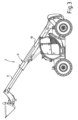
- the telehandler in the usual way, it includes a loading system 2 with a shovel 3 as a load carrier. Furthermore, the telehandler 1 has a chassis 4 with wheels 5, 6 and a driver's cab 7 for the machine operator.
- FIG 2 shows the telehandler according to Figure 1 with the loading system 2 partially raised.
- the telescopic arm 9 is raised to a central position by means of a lifting cylinder 8, but still in retracted condition.
- FIG 3 the telehandler is in accordance with Figure 2 again shown in a raised central position of the loading system 2, with the lifting arm 9 now partially extended.
- the lifting arm 9 can be telescoped in length by moving the telescopic segments 10, 11.
- Figure 4 shows a telehandler according to the previous figures in a top view, with the loading system 2 at the maximum lifting height and fully extended.
- the wheels 5, 6, 12, 13 each have a steering angle.
- the telehandler 1 has all-wheel steering.
- Such telehandlers with all-wheel steering are already commercially available, especially in conjunction with a hydrostatic all-wheel drive. In a known manner, this results in a variety of advantages with regard to the steering radius or the steering behavior or the driving behavior in general.
- Figure 5 the telehandler is in accordance with Figure 4 can be seen, whereby it is clear here that the telescopic loader corresponds to the steering angle (cf. Figure 4 ) shows an inclined position. This can be seen, for example, from the axis T of the telescopic arm 9. This telescope axis has an angle ⁇ relative to the horizontal or an angle of inclination of 90°- ⁇ relative to the vertical. The execution according to Figure 5 achieves this inclination by tilting the entire machine structure relative to the chassis accordingly.
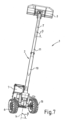
- the Figures 6 and 7 correspond to the Figures 4 and 5 , whereby a larger steering angle of the wheels 5, 6 and 12, 13 is now adopted.
- the angle of inclination is also increased, as in Figure 7 can be seen from the telescope axis T or the vertical longitudinal axis V.
- the angle ⁇ relative to the horizontal is significantly reduced in this position, that is, the corresponding angle of inclination 90°- ⁇ relative to the vertical is correspondingly increased.
- the inclination of the machine structure depends on the steering angle of the wheels 5, 6 or 12, 13.
- a route F is shown, which indicates the normal cornering of the telehandler shown.
- a dashed line shows a compensating movement of the telehandler in the form of a steering reaction, which would be conceivable as a counter-reaction if a tipping moment to the right occurs.
- the center of gravity S is located at the center of the circle with two hatched quadrants used as the center of gravity symbol.
- Two arrows A and I are intended to indicate which forces or moments act during cornering.
- the centrifugal force due to cornering acts outwards in direction A.
- the steering movement carried out as a correction causes a counterforce in the direction of arrow I inwards.
- Such a steering movement can be seen as a counter-reaction, for example in connection with the also in Figure 8 recognizable internal inclination or another machine reaction according to the invention of the telehandler to stabilize the driving dynamics.
- the safety device according to the invention can be designed depending on additional sizes.
- the height of the loading system In addition to the steering or the steering angle, accelerations or speeds or braking processes, the height of the loading system, the length of the loading system can also be taken into account alone or in combination and, in particular, as a function can be used from each other to ensure a stable machine position when driving.
- An example process of how a machine reaction can be controlled depending on various parameters could be as follows. In the starting position, the center of gravity, speed, steering angle and acceleration are recorded using sensors.
- the position of the center of gravity is analyzed with regard to a deflection of the center of gravity. If this results in a critical area, a possible resulting inclination is calculated, which is required as a counter reaction. This inclination is adjusted accordingly. From the detection of the speed, the steering angle and the acceleration, it is simultaneously calculated whether reverse steering is necessary as a steering intervention. If the calculation of the redirection results in a necessary redirection, this is actively carried out.
- the safety device according to the invention can be designed depending on additional sizes.
- the height of the loading system In addition to the steering or the steering angle, accelerations or speeds or braking processes, the height of the loading system, the length of the loading system can also be used alone or in combination and in particular depending on one another in order to achieve a stable machine position when driving cause.
Description
Die Erfindung betrifft eine fahrbare Maschine nach dem Oberbegriff des Anspruchs 1.The invention relates to a mobile machine according to the preamble of
Derartige Maschinen können im Betrieb in einen fahrdynamisch instabilen Betriebszustand gelangen, in dem ein Kippmoment entsteht, das die Maschine zum Umkippen bringen kann. Dies kann während der Fahrt beispielsweise durch den Betrieb der Ladeanlage oder durch Fahrmanöver erfolgen.During operation, such machines can enter an operating state that is unstable in terms of driving dynamics, in which a tipping moment arises that can cause the machine to tip over. This can be done while driving, for example by operating the charging system or by driving maneuvers.
Zur Vermeidung von Instabilitäten bei stehender Maschine wurden im Stand der Technik bereits Maßnahmen ergriffen, die unter anderem auch Eingang in Industrienormen gefunden haben. So gibt es bereits bei handelsüblichen Teleskopladern Sicherheitseinrichtungen, bei denen die Ladeanlage blockiert wird, sobald ein instabiler Zustand droht.To avoid instabilities when the machine is stationary, measures have already been taken in the prior art, which have also found their way into industrial standards, among other things. Commercially available telehandlers already have safety devices that block the loading system as soon as an unstable condition threatens.
Bei diesen Sicherungsmaßnahmen spielt der Einfluss der Fahrdynamik oder der Einfluss der Ladeanlage auf die Fahrdynamik auf die Stabilität jedoch keine Rolle. Instabile Betriebszustände können jedoch vielfach durch die Fahrdynamik während der Fahrt der Maschine auftreten. So spielen nicht nur Größen wie die aufgenommenen Last sowie der Status der Ladeanlage eine große Rolle hinsichtlich der Betriebsstabilität, sondern auch Größen wie die Geschwindigkeit, Kurvenradien und insbesondere Beschleunigungen oder Bremsmanöver.However, with these safety measures, the influence of the driving dynamics or the influence of the charging system on the driving dynamics plays no role in stability. However, unstable operating states can often occur due to the driving dynamics while the machine is moving. Not only variables such as the load carried and the status of the loading system play a major role in terms of operational stability, but also variables such as speed, curve radii and, in particular, acceleration or braking maneuvers.
Auch die geometrischen Verhältnisse des Untergrundes während der Fahrt können die Fahrdynamik und somit Maschinenstabilität beeinflussen, beispielsweise Bodenunebenheiten oder -neigungen sowie wechselnde Reibungskoeffizienten des Untergrunds, was insbesondere bei Fahrten im Gelände häufig auftritt.The geometric conditions of the ground while driving can also influence the driving dynamics and thus machine stability, for example uneven ground or slopes as well as changing friction coefficients of the ground, which often occurs particularly when driving off-road.
In der Druckschrift
Bei diesem Gegenstand ist zwar der Einfluss der Fahrdynamik im Hinblick auf die Instabilität hinsichtlich eines seitlichen Umkippens erkannt, der Nachteil dieser Instabilität bleibt jedoch auch bei diesem Gegenstand erhalten, da das Umkippen nicht verhindert würde.Although the influence of the driving dynamics with regard to the instability with regard to a lateral tipping over is recognized in this object, the disadvantage of this instability remains with this object as well, since the tipping over would not be prevented.
Dokument
Aufgabe der Erfindung ist es daher, eine Maschine der einleitend genannten Art vorzuschlagen, mittels der die Betriebssicherheit erhöht ist.The object of the invention is therefore to propose a machine of the type mentioned in the introduction, by means of which operational safety is increased.
Diese Aufgabe wird ausgehend von einer Maschine nach dem Oberbegriff des Anspruchs 1 durch dessen kennzeichnende Merkmale gelöst.This task is based on a machine according to the preamble of
Durch die in den Unteransprüchen genannten Maßnahmen sind vorteilhafte Ausführungen und Weiterbildungen der Erfindung möglich.The measures mentioned in the subclaims make advantageous embodiments and developments of the invention possible.
Dementsprechend zeichnet sich eine solche fahrbare Maschine dadurch aus, dass eine sensorische Erfassung der Bedienungsart eines Bedienelementes für die Maschine und eine Auswerteeinheit zur Erkennung einer Notsituation einer die Bedieneinheit betätigenden Bedienperson vorgesehen ist und dass eine Kontrolleinheit vorgesehen ist, die nach Erkennung der Notsituation zur selbsttätigen Auslösung eines dem Kippmoment, das die Gefahr des Umkippens der Maschine beinhaltet, entgegenwirkenden Drehmomentes oder zu einer vorbeugenden Maschinenreaktion zur Reduzierung eines solchen Kippmomentes während der Maschinenfahrt mittels wenigstens einem Aktor ausgebildet ist, um einen stabilen Betriebszustand zu erzielen. Als Maschinenreaktion nach Erkennung einer Notsituation sind somit selbsttätige Korrekturmaßnahmen und/oder vorbeugende Korrekturmaßnahmen vorgesehen.Accordingly, such a mobile machine is characterized in that a sensory detection of the operating mode of a control element for the machine and an evaluation unit for detecting an emergency situation of an operator operating the control unit are provided and that a control unit is provided which, after detection of the emergency situation, is used for automatic triggering one the tipping moment, which increases the risk of the machine tipping over includes, counteracting torque or a preventative machine reaction to reduce such a tilting moment during machine travel by means of at least one actuator in order to achieve a stable operating state. Automatic corrective measures and/or preventive corrective measures are therefore provided as a machine reaction after an emergency situation is detected.
Die Erfindung hat somit zum Gegenstand, in einer besonderen Situation, nämlich der Notsituation einer die Bedieneinheit betätigenden Bedienperson, als Maschinenreaktion eine Korrekturmaßnahme vorzusehen. Somit ist es möglich, bei einer auftretenden oder drohenden Instabilität in Verbindung mit einer Notsituation die Maschine und insbesondere deren Fahrdynamik durch Korrekturmaßnahmen zu stabilisieren.The object of the invention is therefore to provide a corrective measure as a machine reaction in a special situation, namely the emergency situation of an operator operating the operating unit. This makes it possible to stabilize the machine and in particular its driving dynamics through corrective measures if instability occurs or is imminent in connection with an emergency situation.
Eine solche Maschine berücksichtigt somit erstmalig die Beeinflussung der Fahrdynamik auf die Maschinenstabilität, indem sie durch eine Maschinenreaktion auf die Fahrdynamik einwirkt, um die Gefahr der Instabilität und insbesondere die Gefahr des Umkippens der Maschine zu vermeiden bzw. zu reduzieren.For the first time, such a machine takes into account the influence of driving dynamics on machine stability by acting on the driving dynamics through a machine reaction in order to avoid or reduce the risk of instability and in particular the risk of the machine tipping over.
Die bisherigen bekannten Sicherungsvorrichtungen bezogen sich lediglich auf den Betrieb der Ladeanlage und waren insbesondere nicht in der Lage, während der Fahrt die nunmehr erfindungsgemäß gegebene Sicherheit zu gewährleisten.The previously known safety devices only related to the operation of the charging system and were in particular not able to guarantee the safety now provided according to the invention while driving.
Der Stand der Technik, der bei Staplern vorgeschlagen wurde, um seitliche Stützen im Falle des Umkippens auszufahren, nimmt dagegen das Umkippen im Falle einer Instabilität in Kauf, da er nicht mit Maschinenreaktionen arbeitet, die auf die Fahrdynamik einwirken.The state of the art, which was proposed for forklift trucks to extend side supports in the event of tipping over, however, accepts tipping over in the event of instability because it does not work with machine reactions that affect the driving dynamics.
Durch die erfindungsgemäße Maschine ist nunmehr erstmalig eine Sicherungseinrichtung vorgesehen, die während der Fahrt unter Berücksichtigung der Fahrdynamik arbeitet. Dabei kann Kippmomenten sowohl in Längsrichtung als auch in Quer-, das heißt in seitlicher Richtung der Maschine vor, während oder nach deren Auftreten entgegengewirkt werden.The machine according to the invention now provides for the first time a safety device which works while driving, taking the driving dynamics into account. Tilting moments can occur both in the longitudinal direction and in the transverse direction, i.e. in the lateral direction of the machine before, during or be counteracted after they occur.
Vorteilhafterweise wird die Notsituation durch Erfassung einer Betätigungsgeschwindigkeit an einem Bedienelement zur Betätigung der Maschine und/oder die Erfassung der Krafteinwirkung auf ein Bedienelement zur Betätigung der Maschine vorgesehen.Advantageously, the emergency situation is provided by detecting an actuation speed on an operating element for operating the machine and/or detecting the force exerted on an operating element for operating the machine.
So wird aufgrund der vorhandenen Notsituation die Betätigung an einem oder mehreren Bedienelementen mit entsprechender Geschwindigkeit oder Krafteinwirkung erfindungsgemäß erfasst und zum Auslösen der Maschinenreaktion verwendet.Due to the existing emergency situation, the actuation of one or more control elements with the appropriate speed or force is detected according to the invention and used to trigger the machine reaction.
Betätigungsgeschwindigkeit an dem Bedienelement wird bevorzugt ein Geschwindigkeitssensor und/oder ein Positionssensor und/oder ein Beschleunigungssensor und/oder ein Kraftsensor an dem oder den Bedienelementen zur Betätigung der Maschine vorgesehen. Mit Hilfe derartiger Sensoren ist die Betätigungsgeschwindigkeit und/oder die Krafteinwirkung auf ein Bedienelement erfassbar.Operating speed on the control element, a speed sensor and/or a position sensor and/or an acceleration sensor and/or a force sensor are preferably provided on the control element(s) for actuating the machine. With the help of such sensors, the actuation speed and/or the force exerted on a control element can be detected.
In einer alternativen Ausführungsform oder als Ergänzung zu den genannten Sensoren kann auch die Erfassung einer Auslöseposition und/oder einer Auslösekrafteinwirkung an einem Bedienelement zur Betätigung der Maschine vorgesehen werden. So kann beispielsweise eine Auslösekraft durch Überwindung eines Widerstandes oder einer Gegenkraft erforderlich sein, um in eine Auslöseposition des Bedienelementes zu gelangen. Dies wäre eine Ausgestaltung, um sicherzustellen, dass die Auslöseposition nur in einer Notsituation erreicht wird. Auch die Tatsache, dass eine Auslösekraft oberhalb der üblichen Krafteinwirkung auf das Bedienelement einwirkt, kann zum Auslösen der Maschinenreaktion verwendet werden. Hierzu ist beispielsweise ein Kraftsensor, wie zuvor beschrieben, verwendbar, wobei bei Übersteigen eines Schwellwertes die Auslösekraft erreicht und somit die Maschinenreaktion ausgelöst wird.In an alternative embodiment or as a supplement to the sensors mentioned, the detection of a trigger position and/or a trigger force effect on a control element for actuating the machine can also be provided. For example, a triggering force may be required by overcoming resistance or a counterforce in order to reach a triggering position of the control element. This would be a design to ensure that the trigger position is only reached in an emergency situation. The fact that a triggering force acts on the control element above the usual force can also be used to trigger the machine reaction. For this purpose, for example, a force sensor, as described above, can be used, whereby when a threshold value is exceeded, the triggering force is reached and the machine reaction is thus triggered.
In einer weiteren alternativen Ausführungsform oder ergänzend zu den oben genannten Maßnahmen zur Erkennung einer Notsituation können auch Sensoren an Maschinenkomponenten vorgesehen werden, die anhand der Betätigung eines Bedienelementes zur Betätigung der Maschine eine sensierbare Zustandsänderung erfahren. Die Charakteristik einer solchen Zustandsänderung kann wiederum Rückschlüsse auf die Bedienart und somit auf eine Notsituation zulassen.In a further alternative embodiment or in addition to the above-mentioned measures for detecting an emergency situation, sensors can also be provided on machine components, which experience a detectable change in state based on the actuation of a control element for actuating the machine. The characteristics of such a change in state can in turn allow conclusions to be drawn about the type of operation and thus about an emergency situation.
So ist beispielsweise denkbar, dass eine für den Normalbetrieb atypische Betätigung eines Bedienelementes sowie der Folgereaktionen an einer oder mehreren Maschinenkomponenten einer Notsituation zugeordnet wird und daraufhin die Maschinenreaktion ausgelöst wird.For example, it is conceivable that an actuation of a control element that is atypical for normal operation and the subsequent reactions on one or more machine components are assigned to an emergency situation and the machine reaction is then triggered.
Die Erfassung wenigstens einer stabilitätsrelevanten Zustandsgröße an einer Maschinenkomponente und/oder von Maschinenreaktionen auf die Bedienart kann somit Rückschlüsse auf eine Notsituation zulassen. Hierzu wird bevorzugt ein Beschleunigungssensor und/oder ein Neigungssensor und/oder ein Ortungssensor und/oder ein Lastsensor und/oder ein Drucksensor und/oder eine Kombination aus zwei oder mehreren solcher Sensoren an wenigstens einer Maschinenkomponente vorgesehen, deren Zustandsänderung oder Reaktion auf Betätigung eines Bedienelementes Rückschlüsse auf eine Notsituation zulässt.The detection of at least one stability-relevant state variable on a machine component and/or machine reactions to the operating mode can thus allow conclusions to be drawn about an emergency situation. For this purpose, an acceleration sensor and/or an inclination sensor and/or a positioning sensor and/or a load sensor and/or a pressure sensor and/or a combination of two or more such sensors is preferably provided on at least one machine component, the change in state of which or response to actuation of a control element allows conclusions to be drawn about an emergency situation.
In einer entsprechenden Auswerteeinheit wird in dieser Ausführungsform durch eine Auswertung der sensorisch erfassten Maschinenreaktion ein Rückschluss auf die Bedienart des Bedienelementes vorgenommen und somit die Notsituation erkannt.In this embodiment, in a corresponding evaluation unit, a conclusion is drawn about the type of operation of the control element by evaluating the sensor-detected machine reaction and the emergency situation is thus recognized.
In einer vorteilhaften Ausführungsform der Erfindung wird eine seitliche Neigungsverstellung oder eine seitliche Verschiebebewegung der Maschine oder einer Maschinenkomponente als Maschinenreaktion vorgesehen, die einem drohenden seitlichen Umkippen der Maschine entgegengerichtet ist. Erfindungsgemäß, ist eine seitliche Neigungsverstellung der Ladeanlage, und/oder eine seitliche Neigungsverstellung der Lastaufnahme der Ladeanlage vorgesehen.In an advantageous embodiment of the invention, a lateral tilt adjustment or a lateral displacement movement of the machine or a machine component is provided as a machine reaction, which is directed against the threat of the machine tipping over sideways. According to the invention, a lateral inclination adjustment of the loading system and/or a lateral inclination adjustment of the load support of the loading system is provided.
Eine solche Neigungsverstellung oder Verschiebebewegung kann zu einer stabileren Fahrdynamik der Maschine führen, beispielsweise wenn diese sich in eine Kurve neigt. Auch bei Fahren in unebenem Gelände kann eine Neigungsverstellung der Maschine einem drohenden Umkippen entgegenwirken.Such an inclination adjustment or displacement movement can lead to more stable driving dynamics of the machine, for example when it leans into a curve. Even when driving on uneven terrain, adjusting the inclination of the machine can prevent the risk of tipping over.
Eine erfindungsgemäße Maschinenreaktion kann beispielweise in der Ladeanlage, dem Fahrantrieb und/oder dem Fahrwerk vorgesehen werden. So kann durch Bewegungen im Bereich der Ladeanlage eine Gegenreaktion oder eine vorbeugende Maßnahme getroffen werden. Der Fahrantrieb kann durch entsprechende Eingriffe während der Fahrt ebenfalls dazu verwendet werden, um ein drohendes Kippmoment zu reduzieren oder zu vermeiden oder um einem bereits aufgetretenen Kippmoment in einer entsprechenden Reaktion entgegenzuwirken.A machine reaction according to the invention can be provided, for example, in the loading system, the travel drive and/or the chassis. Movements in the area of the charging system can trigger a counter-reaction or a preventive measure. The travel drive can also be used by appropriate interventions while driving to reduce or avoid an impending tipping moment or to counteract a tipping moment that has already occurred in a corresponding reaction.
Ebenso kann hierzu das Fahrwerk verwendet werden, beispielsweise indem eine Spurverstellung oder eine Neigungsverstellung vorgesehen wird.The chassis can also be used for this purpose, for example by providing a track adjustment or an inclination adjustment.
So wird in einer besonderen Ausführungsform der Erfindung eine Neigungsverstellung zwischen dem Fahrwerk und einem Maschinenrahmen vorgesehen. Durch diese Anordnung der Neigungsverstellung kann das Fahrwerk in Bodenkontakt verbleiben, während der Maschinenrahmen mit den daran aufgebauten Maschinenkomponenten eine Neigung einnehmen kann, die einem drohenden oder einen bereits vorhandenen Kippmoment entgegenwirkt.In a special embodiment of the invention, an inclination adjustment is provided between the chassis and a machine frame. This arrangement of the inclination adjustment allows the chassis to remain in contact with the ground, while the machine frame with the machine components mounted on it can assume an inclination that counteracts an impending or already existing tilting moment.
Auch eine Verstellung der Ladeanlage während der Fahrt kann zur Stabilisierung der Maschine vorgesehen werden. Insbesondere kann hierzu auch neben den bereits ohnehin vorhandenen Verstellmöglichkeiten der Ladeanlage eine Neigungsverstellung im Bereich der Ladeanlage vorgesehen werden. Auch hierdurch kann einem drohenden oder bereits aufgetretenen Kippmoment entgegengewirkt werden.The loading system can also be adjusted while driving to stabilize the machine. In particular, in addition to the already existing adjustment options for the loading system, an inclination adjustment can be provided in the area of the loading system. This can also counteract an impending or already occurred tipping moment.
Um eine dynamische Stabilität in Längsrichtung der Maschine zu verbessern, kann beispielsweise als Maschinenreaktion auch ein aktives nach vorn oder hinten Neigen der Ladeanlage verwendet werden, was insbesondere beim Bremsen oder Beschleunigen des Fahrzeugs von Vorteil ist.In order to improve dynamic stability in the longitudinal direction of the machine, an active tilting of the loading system forwards or backwards can also be used as a machine reaction which is particularly advantageous when braking or accelerating the vehicle.
Eine Neigungsverstellung kann beispielsweise auch im Bereich der Lastaufnahme der Ladeanlage vorgesehen werden, um eine aufgenommene Last zur Stabilisierung der Maschine zu verwenden. Da im Bereich der Ladeanlage in der Regel ohnehin bereits vielfältige Anschlussmöglichkeiten vorhanden sind, um Arbeitsgeräte oder dergleichen beispielsweise hydraulisch zu betreiben, kann in diesem Bereich auch eine Neigungsverstellung ohne größeren Zusatzaufwand realisiert werden.An inclination adjustment can, for example, also be provided in the area of the load pickup of the loading system in order to use a picked up load to stabilize the machine. Since a variety of connection options are generally already available in the area of the loading system in order to operate implements or the like hydraulically, for example, an inclination adjustment can also be implemented in this area without major additional effort.
Eine erfindungsgemäße Maßnahme gegen ein drohendes Umkippen der Maschinen kann in einer Verschiebung von Maschinenkomponenten und/oder der von der Ladeanlage geladenen Last bestehen. Auch durch derartige Maßnahmen kann einem Kippmoment vorgebeugt oder entgegengewirkt werden.A measure according to the invention to prevent the machines from tipping over can consist of shifting machine components and/or the load loaded by the loading system. Such measures can also prevent or counteract a tipping moment.
Eine Neigungsverstellung der Maschine oder einer Maschinenkomponente wie o. a. kann unterschiedlich realisiert werden. Sie kann bei durchgehenden Achsen beispielsweise über eine Achsverschränkung bewirkt werden. Im Falle einer Pendelachse sind beispielsweise bei handelsüblichen Maschinen Sperrzylinder in Gebrauch, um die Pendelachse unter bestimmten Voraussetzungen zu sperren. Durch das Sperren der Pendelachse wird die Stabilitätszone, innerhalb der sich der Maschinenschwerpunkt befinden muss, vergrößert. Im normalen Fahrbetrieb wird diese Sperre freigegeben, sodass ein Niveauausgleich zwischen den beiden Laufrädern der Pendelachse stattfinden kann. Hierdurch werden die Fahreigenschaften, insbesondere bei Geländefahrt verbessert, da hierdurch ein Bodenkontakt beider Laufräder gewährleistet wird.An inclination adjustment of the machine or a machine component such as the above. can be implemented in different ways. For continuous axes, it can be achieved, for example, by interlocking the axles. In the case of a pendulum axle, for example, locking cylinders are used in commercial machines to lock the pendulum axle under certain conditions. Locking the pendulum axis increases the stability zone within which the machine's center of gravity must be located. During normal driving, this lock is released so that the level can be equalized between the two wheels of the pendulum axle. This improves the driving characteristics, especially when driving off-road, as this ensures that both wheels are in contact with the ground.
Eine aktive Neigungsverstellung der Maschine ist bei diesen bekannten Gegenständen jedoch nicht vorgesehen, könnte jedoch beispielsweise durch Druckbeaufschlagung eines solchen Sperrzylinders ohne größeren Zusatzaufwand realisiert werden. Grundsätzlich kann eine Neigungsverstellung jedoch auch anderweitig, beispielsweise durch separate Hubzylinder oder dergleichen realisiert werden. Somit kann eine Neigungsverstellung auch bei Maschinen vorgesehen werden, die ein anderweitiges Fahrwerk, beispielsweise eine Einzelradaufhängung aufweisen.However, an active tilt adjustment of the machine is not provided for in these known objects, but could be achieved, for example, by pressurizing such a locking cylinder without major additional effort. In principle, however, an inclination adjustment can also be done be realized otherwise, for example by separate lifting cylinders or the like. An inclination adjustment can therefore also be provided for machines that have a different chassis, for example an independent wheel suspension.
Neben den genannten Neigungsverstellungen und/oder
- verschiebungen können erfindungsgemäße Maßnahmen wie bereits oben angedeutet auch im Bereich des Fahrantriebs bzw. des Fahrwerks vorgesehen werden. So können beispielsweise Lenkaktionen verwendet werden, um das drohende Umkippen der fahrbaren Maschine abzufangen. Auch Beschleunigungs- oder Bremsaktionen können dazu verwendet werden, um die Fahrstabilität im erfindungsgemäßen Sinne zu sichern.
- Shifts, measures according to the invention can also be provided in the area of the travel drive or the chassis, as already indicated above. For example, steering actions can be used to prevent the mobile machine from tipping over. Acceleration or braking actions can also be used to ensure driving stability in the sense of the invention.
Diese jeweiligen Lenk-, Beschleunigungs- oder Bremsaktionen können durch selbsttätige Betätigung der ohnehin für den Bediener vorgesehenen Lenk-, Antriebs- oder Bremsaktionen vorgenommen werden.These respective steering, acceleration or braking actions can be carried out by automatically actuating the steering, driving or braking actions that are already intended for the operator.
Es können jedoch zusätzlich auch Eingriffe vorgesehen werden, die einem Bediener im Normalbetrieb nicht zur Verfügung stehen. So können unterschiedliche Beschleunigungs- und/oder Bremsaktionen an wenigstens zwei verschiedenen Laufrädern selbsttätig vorgesehen werden. Ebenso können derartige Eingriffe auch an Antriebsraupen vorgesehen werden, sofern anstelle von Laufrädern ein Raupenantrieb verwendet wird. Erfindungsgemäß, sind unterschiedliche selbsttätige Lenkaktionen an wenigstens zwei Laufrädern und/oder Antriebsraupen vorgesehen.However, additional interventions can also be provided that are not available to an operator in normal operation. In this way, different acceleration and/or braking actions can be provided automatically on at least two different wheels. Such interventions can also be provided on drive tracks, provided that a track drive is used instead of running wheels. According to the invention, different automatic steering actions are provided on at least two wheels and/or drive tracks.
Auch für Bewegungen der Ladeanlage können Beschleunigungen oder Bremsaktionen der Ladeanlage oder von Komponenten der Ladeanlage vorgesehen werden, um die Fahrstabilität der Maschine sicherzustellen. Hierzu können die bereits ohnehin vorhandenen Verstellmöglichkeiten, beispielsweise ein Hubzylinder oder ein Teleskopantrieb oder dergleichen verwendet werden. Es können jedoch für den erfindungsgemäßen Zweck auch zusätzliche Funktionen, beispielsweise Schwenkbewegungen oder dergleichen vorgesehen werden.Acceleration or braking actions of the loading system or components of the loading system can also be provided for movements of the loading system in order to ensure the driving stability of the machine. For this purpose, the already existing adjustment options, for example a lifting cylinder or a telescopic drive or the like, can be used. However, additional functions, for example pivoting movements or the like, can also be provided for the purpose according to the invention.
Alle Maßnahmen, die zur erfindungsgemäßen Stabilisierung der Maschine während der Fahrt geeignet sind, insbesondere die zuvor beschriebenen Maßnahmen können auch untereinander in Kombination vorgesehen werden. Dabei können die Maßnahmen zwar gleichzeitig, aber ansonsten unabhängig voneinander oder aber auch funktional gekoppelt eingesetzt werden. Eine Kopplung wäre beispielsweise der Fall, wenn eine Veränderung eine Größe als Funktion einer anderen Größe stattfindet, zum Beispiel wenn eine geschwindigkeitsabhängige oder beschleunigungsabhängige Lenkreaktion zusammen mit einer Beschleunigungs- oder Bremsreaktion vorgenommen wird, wobei die Größe des Lenkradius und/oder der Beschleunigung abhängig von den jeweiligen anderen Werten beeinflusst wird.All measures that are used to stabilize the according to the invention Machine are suitable while driving, in particular the measures described above can also be provided in combination with one another. The measures can be used simultaneously, but otherwise independently of one another or functionally coupled. A coupling would be the case, for example, if a change in one variable takes place as a function of another variable, for example if a speed-dependent or acceleration-dependent steering reaction is carried out together with an acceleration or braking reaction, the size of the steering radius and / or the acceleration depending on the respective other values.
Neben den beschriebenen nach Auslösung selbsttätig einsetzenden Maschinenreaktionen sind jedoch erfindungsgemäß auch vorbeugende Maßnahmen denkbar, die einem drohenden Kippmoment bereits vor dessen Auftreten entgegen wirken. So kann beispielsweise präventiv auf die möglichen Betriebsbedingungen Einfluss genommen werden, die über die Bedienung durch die Bedienperson erreichbar sind.In addition to the described machine reactions that occur automatically after triggering, preventive measures are also conceivable according to the invention, which counteract an impending tipping moment before it occurs. For example, it is possible to preventively influence the possible operating conditions that can be achieved via the operation by the operator.
Beispielsweise kann abhängig von einer Geschwindigkeit und/oder einer Beschleunigung und/oder einer Lenkeinstellung und/oder von dem Zustand der Ladeanlage die Ansteuerbarkeit einer oder mehrerer dieser Parameter beeinflusst werden. Es kann beispielsweise bei einer gewissen Geschwindigkeit oder Beschleunigung nur ein bestimmter Bereich von Lenkradien zugelassen werden. Auch der zulässige Zeitablauf von Lenkbewegungen kann so verändert werden.For example, the controllability of one or more of these parameters can be influenced depending on a speed and/or an acceleration and/or a steering setting and/or on the state of the charging system. For example, at a certain speed or acceleration, only a certain range of steering directions can be permitted. The permissible timing of steering movements can also be changed in this way.
Ebenso können beispielsweise abhängig von einer Lenkbewegung nur ein bestimmter Geschwindigkeitsbereich oder ein bestimmter Beschleunigungsverlauf zugelassen werden. Auch der Verlauf von Bremsmanövern kann entsprechend beeinflusst werden. Die präventiven Eingriffe können beispielsweise auch abhängig von Bremsbetätigungen bei der Lenkung und/oder der Geschwindigkeit und/oder der Verstellung und/oder der Last der Ladeanlage vorgesehen werden.Likewise, depending on a steering movement, for example, only a certain speed range or a certain acceleration curve can be permitted. The course of braking maneuvers can also be influenced accordingly. The preventive interventions can also be provided, for example, depending on brake actuations in the steering and/or the speed and/or the adjustment and/or the load of the loading system.
Erfindungsgemäß sind somit präventive Maßnahmen als Maschinenreaktion während der Fahrt im Hinblick auf die mögliche bedienerseitige Betätigung der Maschine ebenso einsetzbar, wie aktive selbsttätige Maschineneingriffe zur Stabilisierung der Maschine.According to the invention, preventive measures can therefore be used as a machine reaction while driving with regard to the possible operator-side operation of the machine, as can active automatic machine interventions to stabilize the machine.
Grundsätzlich sind alle Maßnahmen erfindungsgemäß einsetzbar, die dafür Sorge tragen, dass sich die Schwerpunktslage der Maschine innerhalb der in der jeweiligen Betriebssituation vorliegenden Stabilitätszone der Maschine befindet.In principle, all measures can be used according to the invention that ensure that the center of gravity of the machine is within the stability zone of the machine in the respective operating situation.
Durch die erfindungsgemäße Verbesserung der Stabilität der Maschine während der Fahrt ist eine solche Maschine nicht nur sicherer, sondern auch wirtschaftlicher zu betreiben, da beispielsweise die Umschlagzeiten der bewegten Güter verkürzt werden können.By improving the stability of the machine while driving according to the invention, such a machine is not only safer to operate, but also more economical, since, for example, the turnover times of the goods being moved can be shortened.
Zur Erfassung der Instabilität sind vielfältige Sensoren denkbar. So kann beispielsweise eine Druckdifferenz in einem Neigezylinder oder eine Druckdifferenz in Radnaben durch entsprechende Drucksensoren oder sonstigen Neigungssensoren erfasst werden.A variety of sensors are conceivable for detecting instability. For example, a pressure difference in a tilt cylinder or a pressure difference in wheel hubs can be detected by appropriate pressure sensors or other inclination sensors.
Eine Möglichkeit zur Sensorik eines Kippmomentes ist beispielsweise auch durch eine Luftdruckmessung in den Laufrädern gemessen. Auch Biegesensoren an verschiedenen Maschinenkomponenten sind beispielsweise verwendbar.One possibility for sensing a tipping moment is, for example, by measuring the air pressure in the wheels. Bending sensors on various machine components can also be used, for example.
Darüber hinaus können auch Beschleunigungssensoren, vorzugsweise im Bereich der Schwerpunktslage vorgesehen werden.In addition, acceleration sensors can also be provided, preferably in the area of the center of gravity.
Hilfreich ist auch die Messung der Lastverteilung, beispielsweise durch Wägezellen in unterschiedlichen Maschinenkomponenten, beispielsweise in den Radköpfen. Dies ergibt auch die Möglichkeit, die Schwerpunktslage zu bestimmen.Measuring the load distribution, for example using load cells in different machine components, for example in the wheel heads, is also helpful. This also makes it possible to determine the center of gravity.
Eine weitere Möglichkeit der sensorischen Datenerfassung besteht darin, den Zustand von Bedienorganen zu erfassen, die von der Bedienperson betätigt werden. Dabei kommen sowohl Bedienorgane in Betracht, die zur Erkennung einer Notsituation überwacht werden, als auch alle sonstigen Bedienorgane. Auch der zeitliche Verlauf der Betätigung insbesondere vor Eintritt der Notsituation kann zur sensorischen Datenerfassung herangezogen und gegebenenfalls gespeichert werden. So können beispielsweise über die Bedienung eines Gaspedals oder eines Lenkrads mittels entsprechender Sensoren an den Bedienorganen Daten gewonnen werden, die einen Rückschluss auf Geschwindigkeiten, Beschleunigungen, Lenkradien, Lenkverläufe und dergleichen erlauben.Another option for sensory data collection consists of detecting the status of operating elements that are operated by the operator. Both operating elements that are monitored to detect an emergency situation and all other operating elements come into consideration. The time course of the actuation, in particular before the emergency situation occurs, can also be used for sensory data acquisition and, if necessary, saved. For example, by operating an accelerator pedal or a steering wheel using appropriate sensors on the operating elements, data can be obtained that allows conclusions to be drawn about speeds, accelerations, steering directions, steering curves and the like.
Weiterhin können zur Erfassung der Instabilität auch Daten (-) genutzt werden, bei denen die Umgebung der Maschine, (beispielsweise eine Umgebungskarte), Berücksichtigung findet. Insbesondere vorbeugende Maßnahmen sind sowohl gespeicherte Daten als auch sensorisch erfasste Daten verwendbar. Insbesondere kann auch ein Fahrbahnsensor zur Erfassung der Fahrbahnqualität, beispielsweise hinsichtlich der Oberflächenbeschaffenheit, der Kontur, der möglichen Friktion, oder dergleichen verwendbar. Parameter über die Umgebung der Maschine bzw. eine Geländeüberwachung können beispielsweise über Kameras, Ortungssysteme (GPS, Lasersensoren, Radarsensoren, usw.) vorgesehen werden, um die Fahrbahn bzw. Fahrweg zu analysieren und mögliche Stellgrößen zu erfassen.Furthermore, data (-) can also be used to record instability, which takes the machine's surroundings (for example an environmental map) into account. In particular, both stored data and sensory data can be used for preventive measures. In particular, a road sensor can also be used to record the quality of the road, for example with regard to the surface quality, the contour, the possible friction, or the like. Parameters about the machine's surroundings or terrain monitoring can be provided, for example, via cameras, positioning systems (GPS, laser sensors, radar sensors, etc.) in order to analyze the road or route and record possible manipulated variables.
Die Intensität, mittels der Korrekturmaßnahmen zur Herstellung der Maschinenstabilität vorgenommen werden, kann ebenfalls abhängig von gemessenen Werten, beispielsweise von einer Geschwindigkeit, einer Beschleunigung oder einer Druckdifferenz zur Erfassung eines drohenden Kippmoments vorgenommen werden.The intensity with which corrective measures are taken to establish machine stability can also be carried out depending on measured values, for example a speed, an acceleration or a pressure difference to detect an impending tipping moment.
Ein Ausführungsbeispiel der Erfindung ist in der Zeichnung dargestellt und wird anhand der Figuren nachfolgend näher erläutert.An exemplary embodiment of the invention is shown in the drawing and is explained in more detail below with reference to the figures.
Im Einzelnen zeigen:
Figur 1- eine Seitenansicht eines erfindungsgemäßen Teleskopladers mit Ladeanlage in Ausgangsstellung,
Figur 2- eine Seitenansicht eines Teleskopladers gemäß
Figur 1 mit teilweise angehobener Ladeanlage, Figur 3- eine Seitenansicht eines Teleskopladers gemäß
Figur 2 mit teilweise ausgefahrener Ladeanlage, Figur 4- eine Draufsicht eines Teleskopladers mit ausgefahrener und angehobener Ladeanlage in erfindungsgemäß geneigter Stellung,
Figur 5- trägt eine Rückansicht des Teleskopladers gemäß
Figur 4 , Figur 6- zeigt eine Draufsicht des Teleskopladers gemäß
Figur 4 mit verändertem Lenkeinschlag und veränderter Neigung, Figur 7- zeigt eine Rückansicht des Teleskopladers gemäß
Figur 6 und - Figur 8
- zeigt eine
Figur 6 entsprechende Darstellung mit angedeuteter Lenkbewegung als zusätzliche Maschinenreaktion.
- Figure 1
- a side view of a telehandler according to the invention with loading system in the starting position,
- Figure 2
- a side view of a telehandler according to
Figure 1 with partially raised loading system, - Figure 3
- a side view of a telehandler according to
Figure 2 with partially extended loading system, - Figure 4
- a top view of a telehandler with the loading system extended and raised in an inclined position according to the invention,
- Figure 5
- carries a rear view of the telehandler according to
Figure 4 , - Figure 6
- shows a top view of the telehandler according to
Figure 4 with changed steering angle and changed inclination, - Figure 7
- shows a rear view of the telehandler according to
Figure 6 and - Figure 8
- shows one
Figure 6 Corresponding representation with indicated steering movement as an additional machine reaction.
Der Teleskoplader gemäß
In
In
Die
In
Wie vorstehend bereits beschrieben ist, kann die erfindungsgemäße Sicherheitseinrichtung von zusätzlichen Größen abhängig ausgestaltet werden. Neben der Lenkung bzw. dem Lenkeinschlag, Beschleunigungen oder Geschwindigkeiten bzw. Bremsvorgängen können hierbei auch die eingenommene Höhe der Ladeanlage, die Länge der Ladeanlage für sich alleine oder in Kombination und insbesondere auch in Abhängigkeit voneinander dazu herangezogen werden, um eine stabile Maschinenposition im Fahrbetrieb zu bewirken.As already described above, the safety device according to the invention can be designed depending on additional sizes. In addition to the steering or the steering angle, accelerations or speeds or braking processes, the height of the loading system, the length of the loading system can also be taken into account alone or in combination and, in particular, as a function can be used from each other to ensure a stable machine position when driving.
Ein beispielhafter Prozess, wie eine Maschinenreaktion abhängig von verschiedenen Parametern gesteuert werden kann, könnte wie folgt ablaufen. In der Ausgangsposition werden Schwerpunktlage, Geschwindigkeit, der Lenkungswinkel sowie die Beschleunigung sensorisch erfasst.An example process of how a machine reaction can be controlled depending on various parameters could be as follows. In the starting position, the center of gravity, speed, steering angle and acceleration are recorded using sensors.
Die Schwerpunktslage wird hinsichtlich einer Schwerpunktsauslenkung analysiert. Ergibt sich hieraus ein kritischer Bereich, so wird eine sich daraus möglicherweise ergebende Neigung berechnet, die als Gegenreaktion erforderlich ist. Diese Neigung wird entsprechend eingestellt. Aus der Erfassung der Geschwindigkeit, dem Lenkungswinkel sowie der Beschleunigung wird gleichzeitig berechnet, ob eine Rücklenkung als Lenkeingriff notwendig ist. Sofern die Berechnung der Rücklenkung eine notwendige Rücklenkung ergibt, wird diese aktiv vorgenommen.The position of the center of gravity is analyzed with regard to a deflection of the center of gravity. If this results in a critical area, a possible resulting inclination is calculated, which is required as a counter reaction. This inclination is adjusted accordingly. From the detection of the speed, the steering angle and the acceleration, it is simultaneously calculated whether reverse steering is necessary as a steering intervention. If the calculation of the redirection results in a necessary redirection, this is actively carried out.
Nach erfolgter Neigungsverstellung und/oder Rücklenkung wird erneut berechnet, ob die ausgleichenden Kräfte bzw. Momente ausgeglichen sind. Führt diese Prüfung zu einem positiven Ergebnis, beginnt das Verfahren von vorn. Erfolgt ein negatives Ergebnis, wird eine erneute Berechnung der erforderlichen Rücklenkung sowie der erforderlichen Neigung unmittelbar durchgeführt.After the tilt adjustment and/or return steering has been carried out, it is calculated again whether the compensating forces or moments are balanced. If this test produces a positive result, the process begins again. If a negative result is obtained, a new calculation of the required deflection and the required inclination is carried out immediately.
Wie vorstehend bereits beschrieben ist, kann die erfindungsgemäße Sicherheitseinrichtung von zusätzlichen Größen abhängig ausgestaltet werden. Neben der Lenkung bzw. dem Lenkeinschlag, Beschleunigungen oder Geschwindigkeiten bzw. Bremsvorgängen können hierbei auch die eingenommene Höhe der Ladeanlage, die Länge der Ladeanlage für sich alleine oder in Kombination und insbesondere auch in Abhängigkeit voneinander dazu herangezogen werden, um eine stabile Maschinenposition im Fahrbetrieb zu bewirken.As already described above, the safety device according to the invention can be designed depending on additional sizes. In addition to the steering or the steering angle, accelerations or speeds or braking processes, the height of the loading system, the length of the loading system can also be used alone or in combination and in particular depending on one another in order to achieve a stable machine position when driving cause.
- 11
- TeleskopladerTelehandler
- 22
- LadeanlageCharging system
- 33
- Schaufelshovel
- 44
- Fahrwerklanding gear
- 55
- LaufradWheel
- 66
- LaufradWheel
- 77
- FahrerkabineDriver's cab
- 88th
- Hubzylinderlifting cylinder
- 99
- TeleskoparmTelescopic arm
- 1010
- TeleskopsegmentTelescopic segment
- 1111
- TeleskopsegmentTelescopic segment
- 1212
- LaufradWheel
- 1313
- LaufradWheel
- TT
- TeleskopachseTelescopic axis
- Vv
- VertikalachseVertical axis
Claims (8)
- Mobile machine with a loading system, a traction drive and a chassis, such as a wheeled loader, a telescopic loader or the like, wherein one or more sensors are provided for identifying an unstable operating state or an imminent unstable operating state while underway, said unstable operating state including a tipping moment with the risk of the machine tipping over laterally, wherein a sensor-based detection of the manner of operation of an operator control element for the machine and an evaluation unit for identifying an emergency situation of an operator actuating an operator control unit are provided, and in that a control unit is provided which is designed so as, after identification of the emergency situation, to use at least one actuator to automatically trigger a torque counteracting the tipping moment, which includes the risk of the machine tipping over, or for a preventative machine reaction for avoiding and/or reducing such a tipping moment during movement of the machine, in order to achieve a stable operating state, wherein the machine reaction is provided in the loading system and/or in the traction drive and/or in the chassis,
characterized in that different automatic steering actions at at least two running wheels and/or drive tracks are provided, in that a lateral inclination adjustment of the loading system is provided, and/or in that the lateral inclination adjustment of the load absorption of the loading system is provided, and/or in that a lateral displacement of machine components and/or of the load loaded by the loading system, said lateral displacement counteracting the imminent tipping over of the machine, is provided. - Machine according to Claim 1, characterized in that a lateral inclination adjustment of the machine directed counter to an imminent lateral tipping over of the machine is provided.
- Machine according to either of the preceding claims, characterized in that the machine reaction is provided at a driving speed of ≥ 0 km/h.
- Machine according to one of the preceding claims, characterized in that a lateral inclination adjustment is provided between the chassis and a machine frame.
- Machine according to one of the preceding claims, characterized in that an automatic steering and/or acceleration and/or braking action of the machine is provided.
- Machine according to one of the preceding claims, characterized in that an automatic acceleration and/or braking action of the loading system and/or of components of the loading system is provided.
- Machine according to one of the preceding claims, characterized in that a change in the permitted values of machine parameters which are controllable by an operator is provided as the preventative machine reaction.
- Machine according to one of the preceding claims, characterized in that a pressure gauge for the pressure in at least one cylinder provided for deflecting a full-floating axle of the chassis is provided as sensor.
Applications Claiming Priority (2)
| Application Number | Priority Date | Filing Date | Title |
|---|---|---|---|
| DE202012012524U DE202012012524U1 (en) | 2012-11-16 | 2012-11-16 | "Mobile machine with charging system" |
| DE102013003511 | 2013-03-04 |
Publications (3)
| Publication Number | Publication Date |
|---|---|
| EP2733036A2 EP2733036A2 (en) | 2014-05-21 |
| EP2733036A3 EP2733036A3 (en) | 2018-05-02 |
| EP2733036B1 true EP2733036B1 (en) | 2024-01-17 |
Family
ID=49666908
Family Applications (1)
| Application Number | Title | Priority Date | Filing Date |
|---|---|---|---|
| EP13005274.9A Active EP2733036B1 (en) | 2012-11-16 | 2013-11-08 | Mobile machine with loading system |
Country Status (2)
| Country | Link |
|---|---|
| EP (1) | EP2733036B1 (en) |
| DE (1) | DE102013018510A1 (en) |
Families Citing this family (3)
| Publication number | Priority date | Publication date | Assignee | Title |
|---|---|---|---|---|
| US11131076B2 (en) | 2018-09-05 | 2021-09-28 | Deere & Company | Controlling a work machine based on in-rubber tire/track sensor |
| DE102019207141A1 (en) * | 2019-05-16 | 2020-11-19 | Robert Bosch Gmbh | Method for analyzing the use of a work machine |
| US11707983B2 (en) | 2020-01-30 | 2023-07-25 | Deere & Company | Sensing track characteristics on a track vehicle using replaceable track sensors |
Citations (1)
| Publication number | Priority date | Publication date | Assignee | Title |
|---|---|---|---|---|
| US20050102083A1 (en) * | 2003-11-06 | 2005-05-12 | Ford Global Technologies, Llc | Roll stability control system for an automotive vehicle using an external environmental sensing system |
Family Cites Families (7)
| Publication number | Priority date | Publication date | Assignee | Title |
|---|---|---|---|---|
| DE10010011A1 (en) * | 1999-07-27 | 2001-02-01 | Linde Ag | Warehouse transport vehicle has stabilising device for increasing stability, wheel load sensors for each wheel connected to monitoring device controlling lifting and/or drive systems |
| NL1016045C1 (en) | 2000-08-29 | 2002-03-01 | Christiaan Johan Jansen | Improved implementation and placement of anti-crushing device on forklift trucks or articulated loaders. |
| GB2390595B (en) * | 2002-07-12 | 2005-08-24 | Bamford Excavators Ltd | Control system for a machine |
| WO2007081020A1 (en) * | 2006-01-16 | 2007-07-19 | Mitsubishi Heavy Industries, Ltd. | Forklift truck and control method for preventing overturning of forklift truck |
| DE102007019506A1 (en) * | 2007-04-25 | 2008-10-30 | Jungheinrich Ag | Method and device for preventing tilting of a counterbalance truck |
| CN101786454A (en) * | 2010-02-03 | 2010-07-28 | 无锡市亦清轩数码动漫设计有限公司 | Automatic safety control system of electric vehicle and control method thereof |
| ITMO20100296A1 (en) * | 2010-10-25 | 2012-04-26 | Bordini Engineering Srl | SYSTEM AND METHOD TO PREVENT A TILTING OF LAND VEHICLES |
-
2013
- 2013-11-06 DE DE102013018510.6A patent/DE102013018510A1/en active Pending
- 2013-11-08 EP EP13005274.9A patent/EP2733036B1/en active Active
Patent Citations (1)
| Publication number | Priority date | Publication date | Assignee | Title |
|---|---|---|---|---|
| US20050102083A1 (en) * | 2003-11-06 | 2005-05-12 | Ford Global Technologies, Llc | Roll stability control system for an automotive vehicle using an external environmental sensing system |
Also Published As
| Publication number | Publication date |
|---|---|
| EP2733036A3 (en) | 2018-05-02 |
| EP2733036A2 (en) | 2014-05-21 |
| DE102013018510A1 (en) | 2014-05-22 |
Similar Documents
| Publication | Publication Date | Title |
|---|---|---|
| DE102005012004B4 (en) | Industrial truck with increased static / quasi-static and dynamic tipping stability | |
| EP1640311B1 (en) | Method for preventing tipping over of rear wheel steered vehicles, in particular of industrial trucks | |
| EP2477930B1 (en) | Load-carrying vehicle with vertically adjustable lifting device | |
| EP1601561B1 (en) | Method and system for controlling the driving stability of a vehicle and use of said system | |
| EP1985576B1 (en) | Method and device for preventing a counterweight forklift tipping over | |
| EP2829438B1 (en) | Tipping vehicle | |
| DE102005018069B4 (en) | Control for active wheel steering | |
| EP2580152B1 (en) | Method for determining the probability of a handling truck's tipping over | |
| WO2004069568A1 (en) | System for safeguarding the driving stability of an industrial truck | |
| EP2205456A1 (en) | Device and method for automatically adjusting the horizontal ride level of a utility vehicle | |
| EP1882117A1 (en) | Method for controlling the driving operation of motor vehicles or other vehicles | |
| EP2987694B1 (en) | Method for controlling braking in a vehicle and a vehicle having a control unit in which the method is executed | |
| DE102014202230A1 (en) | Method and apparatus for preventing tipping of a steerable vehicle | |
| DE10010011A1 (en) | Warehouse transport vehicle has stabilising device for increasing stability, wheel load sensors for each wheel connected to monitoring device controlling lifting and/or drive systems | |
| DE102009054293B4 (en) | Method for steering a trailer | |
| EP3990336A1 (en) | Method and device for stabilising a tractor vehicle-trailer combination, and control unit | |
| DE10348736B4 (en) | Control system for a vehicle and method for controlling a vehicle | |
| DE102005011998B4 (en) | Industrial truck with increased static or quasi-static tipping stability | |
| EP2733036B1 (en) | Mobile machine with loading system | |
| DE102016106459A1 (en) | Work vehicle with articulated steering and load-dependent steering angle limitation | |
| DE102008052131B4 (en) | Method and device for increasing the safety of a motor vehicle in a critical driving situation | |
| DE10226599A1 (en) | Method for controlling at least one movement of an industrial truck | |
| EP2774889B1 (en) | Mobile machine with loading system | |
| EP2937252A1 (en) | Agricultural vehicle, in particular a tractor | |
| EP3115332B1 (en) | Method for controlling an industrial truck |
Legal Events
| Date | Code | Title | Description |
|---|---|---|---|
| PUAI | Public reference made under article 153(3) epc to a published international application that has entered the european phase |
Free format text: ORIGINAL CODE: 0009012 |
|
| 17P | Request for examination filed |
Effective date: 20131108 |
|
| AK | Designated contracting states |
Kind code of ref document: A2 Designated state(s): AL AT BE BG CH CY CZ DE DK EE ES FI FR GB GR HR HU IE IS IT LI LT LU LV MC MK MT NL NO PL PT RO RS SE SI SK SM TR |
|
| AX | Request for extension of the european patent |
Extension state: BA ME |
|
| PUAL | Search report despatched |
Free format text: ORIGINAL CODE: 0009013 |
|
| AK | Designated contracting states |
Kind code of ref document: A3 Designated state(s): AL AT BE BG CH CY CZ DE DK EE ES FI FR GB GR HR HU IE IS IT LI LT LU LV MC MK MT NL NO PL PT RO RS SE SI SK SM TR |
|
| AX | Request for extension of the european patent |
Extension state: BA ME |
|
| RIC1 | Information provided on ipc code assigned before grant |
Ipc: B60W 10/04 20060101ALN20180326BHEP Ipc: B60W 30/02 20120101AFI20180326BHEP Ipc: B60W 10/184 20120101ALN20180326BHEP Ipc: B60W 30/04 20060101ALI20180326BHEP Ipc: B66F 9/065 20060101ALI20180326BHEP Ipc: B60W 10/20 20060101ALN20180326BHEP Ipc: B66F 17/00 20060101ALI20180326BHEP |
|
| STAA | Information on the status of an ep patent application or granted ep patent |
Free format text: STATUS: REQUEST FOR EXAMINATION WAS MADE |
|
| R17P | Request for examination filed (corrected) |
Effective date: 20181022 |
|
| RBV | Designated contracting states (corrected) |
Designated state(s): AL AT BE BG CH CY CZ DE DK EE ES FI FR GB GR HR HU IE IS IT LI LT LU LV MC MK MT NL NO PL PT RO RS SE SI SK SM TR |
|
| STAA | Information on the status of an ep patent application or granted ep patent |
Free format text: STATUS: EXAMINATION IS IN PROGRESS |
|
| 17Q | First examination report despatched |
Effective date: 20190213 |
|
| STAA | Information on the status of an ep patent application or granted ep patent |
Free format text: STATUS: EXAMINATION IS IN PROGRESS |
|
| STAA | Information on the status of an ep patent application or granted ep patent |
Free format text: STATUS: EXAMINATION IS IN PROGRESS |
|
| RIC1 | Information provided on ipc code assigned before grant |
Ipc: B60W 10/20 20060101ALN20230831BHEP Ipc: B60W 10/184 20120101ALN20230831BHEP Ipc: B60W 10/04 20060101ALN20230831BHEP Ipc: B66F 9/065 20060101ALI20230831BHEP Ipc: B66F 17/00 20060101ALI20230831BHEP Ipc: B60W 30/04 20060101ALI20230831BHEP Ipc: B60W 30/02 20120101AFI20230831BHEP |
|
| GRAP | Despatch of communication of intention to grant a patent |
Free format text: ORIGINAL CODE: EPIDOSNIGR1 |
|
| STAA | Information on the status of an ep patent application or granted ep patent |
Free format text: STATUS: GRANT OF PATENT IS INTENDED |
|
| RIC1 | Information provided on ipc code assigned before grant |
Ipc: B60W 10/20 20060101ALN20230925BHEP Ipc: B60W 10/184 20120101ALN20230925BHEP Ipc: B60W 10/04 20060101ALN20230925BHEP Ipc: B66F 9/065 20060101ALI20230925BHEP Ipc: B66F 17/00 20060101ALI20230925BHEP Ipc: B60W 30/04 20060101ALI20230925BHEP Ipc: B60W 30/02 20120101AFI20230925BHEP |
|
| INTG | Intention to grant announced |
Effective date: 20231023 |
|
| GRAS | Grant fee paid |
Free format text: ORIGINAL CODE: EPIDOSNIGR3 |
|
| GRAA | (expected) grant |
Free format text: ORIGINAL CODE: 0009210 |
|
| STAA | Information on the status of an ep patent application or granted ep patent |
Free format text: STATUS: THE PATENT HAS BEEN GRANTED |
|
| AK | Designated contracting states |
Kind code of ref document: B1 Designated state(s): AL AT BE BG CH CY CZ DE DK EE ES FI FR GB GR HR HU IE IS IT LI LT LU LV MC MK MT NL NO PL PT RO RS SE SI SK SM TR |
|
| REG | Reference to a national code |
Ref country code: GB Ref legal event code: FG4D Free format text: NOT ENGLISH |
|
| REG | Reference to a national code |
Ref country code: DE Ref legal event code: R096 Ref document number: 502013016488 Country of ref document: DE |
|
| REG | Reference to a national code |
Ref country code: CH Ref legal event code: EP |
|
| REG | Reference to a national code |
Ref country code: IE Ref legal event code: FG4D Free format text: LANGUAGE OF EP DOCUMENT: GERMAN |