EP2732229B1 - Dephlegmator - Google Patents
Dephlegmator Download PDFInfo
- Publication number
- EP2732229B1 EP2732229B1 EP12750817.4A EP12750817A EP2732229B1 EP 2732229 B1 EP2732229 B1 EP 2732229B1 EP 12750817 A EP12750817 A EP 12750817A EP 2732229 B1 EP2732229 B1 EP 2732229B1
- Authority
- EP
- European Patent Office
- Prior art keywords
- tubes
- group
- dephlegmator
- tube bundle
- outlet ends
- Prior art date
- Legal status (The legal status is an assumption and is not a legal conclusion. Google has not performed a legal analysis and makes no representation as to the accuracy of the status listed.)
- Active
Links
Images



Classifications
-
- B—PERFORMING OPERATIONS; TRANSPORTING
- B01—PHYSICAL OR CHEMICAL PROCESSES OR APPARATUS IN GENERAL
- B01D—SEPARATION
- B01D5/00—Condensation of vapours; Recovering volatile solvents by condensation
- B01D5/0003—Condensation of vapours; Recovering volatile solvents by condensation by using heat-exchange surfaces for indirect contact between gases or vapours and the cooling medium
- B01D5/0009—Horizontal tubes
-
- F—MECHANICAL ENGINEERING; LIGHTING; HEATING; WEAPONS; BLASTING
- F28—HEAT EXCHANGE IN GENERAL
- F28B—STEAM OR VAPOUR CONDENSERS
- F28B1/00—Condensers in which the steam or vapour is separate from the cooling medium by walls, e.g. surface condenser
- F28B1/06—Condensers in which the steam or vapour is separate from the cooling medium by walls, e.g. surface condenser using air or other gas as the cooling medium
-
- F—MECHANICAL ENGINEERING; LIGHTING; HEATING; WEAPONS; BLASTING
- F28—HEAT EXCHANGE IN GENERAL
- F28B—STEAM OR VAPOUR CONDENSERS
- F28B9/00—Auxiliary systems, arrangements, or devices
-
- F—MECHANICAL ENGINEERING; LIGHTING; HEATING; WEAPONS; BLASTING
- F28—HEAT EXCHANGE IN GENERAL
- F28D—HEAT-EXCHANGE APPARATUS, NOT PROVIDED FOR IN ANOTHER SUBCLASS, IN WHICH THE HEAT-EXCHANGE MEDIA DO NOT COME INTO DIRECT CONTACT
- F28D1/00—Heat-exchange apparatus having stationary conduit assemblies for one heat-exchange medium only, the media being in contact with different sides of the conduit wall, in which the other heat-exchange medium is a large body of fluid, e.g. domestic or motor car radiators
- F28D1/02—Heat-exchange apparatus having stationary conduit assemblies for one heat-exchange medium only, the media being in contact with different sides of the conduit wall, in which the other heat-exchange medium is a large body of fluid, e.g. domestic or motor car radiators with heat-exchange conduits immersed in the body of fluid
- F28D1/04—Heat-exchange apparatus having stationary conduit assemblies for one heat-exchange medium only, the media being in contact with different sides of the conduit wall, in which the other heat-exchange medium is a large body of fluid, e.g. domestic or motor car radiators with heat-exchange conduits immersed in the body of fluid with tubular conduits
- F28D1/053—Heat-exchange apparatus having stationary conduit assemblies for one heat-exchange medium only, the media being in contact with different sides of the conduit wall, in which the other heat-exchange medium is a large body of fluid, e.g. domestic or motor car radiators with heat-exchange conduits immersed in the body of fluid with tubular conduits the conduits being straight
- F28D1/05316—Assemblies of conduits connected to common headers, e.g. core type radiators
- F28D1/05325—Assemblies of conduits connected to common headers, e.g. core type radiators with particular pattern of flow, e.g. change of flow direction
-
- F—MECHANICAL ENGINEERING; LIGHTING; HEATING; WEAPONS; BLASTING
- F28—HEAT EXCHANGE IN GENERAL
- F28B—STEAM OR VAPOUR CONDENSERS
- F28B1/00—Condensers in which the steam or vapour is separate from the cooling medium by walls, e.g. surface condenser
- F28B1/02—Condensers in which the steam or vapour is separate from the cooling medium by walls, e.g. surface condenser using water or other liquid as the cooling medium
-
- F—MECHANICAL ENGINEERING; LIGHTING; HEATING; WEAPONS; BLASTING
- F28—HEAT EXCHANGE IN GENERAL
- F28F—DETAILS OF HEAT-EXCHANGE AND HEAT-TRANSFER APPARATUS, OF GENERAL APPLICATION
- F28F2210/00—Heat exchange conduits
- F28F2210/10—Particular layout, e.g. for uniform temperature distribution
Definitions
- This invention relates to a dephlegmator of the type employed in steam condensation installations in order to separate non-condensable gases from condensable gases.
- a dephlegmator assumes the form of a secondary reflux condenser that serves to remove non-condensable gases from what is generally steam in one form or another.
- a dephlegmator of this type is typically used in a steam condensation installation downstream of steam turbines used in electricity generating power plants and downstream of primary condensers.
- a direct A-frame air-cooled steam condenser system of the type widely used in power plants the steam exiting a steam turbine is fed via a steam header to a primary condenser arrangement and residual steam leaving the primary condenser arrangement is condensed in a dephlegmator that allows non-condensable gases to be separated out and typically vented to atmosphere.
- dephlegmators are available in either dry cooling or wet cooling varieties and for reasons set out above, dry cooling may often be preferred in spite of the disadvantage indicated.
- the air cooled reflux condenser comprises multiple finned tubes extending downwards at the incline towards each other in an inverted A-frame type of arrangement; and the tube bundle is located at the lower ends of the finned tubes; and wherein one or more fans are positioned in the region of the upper ends of the downwardly inclined tubes for drawing air upwards past the finned tubes and towards the horizontal tube bundle.
- Further features of the invention provide for an arrangement of spray nozzles to be installed above the tube bundle whereby water can be sprayed onto the tube bundle in order to provide the evaporatively cooled mode; for drift eliminators to be positioned above the arrangement of spray nozzles to inhibit loss of water in the form of airborne droplets; and for one or more collection troughs to be provided beneath the tube bundle for collecting run-off water and enabling recycling of excess deluge water.
- Embodiments of the invention provide for the tube bundle to comprise at least two groups of tubes including a first group of tubes that have inlet ends and outlet ends and a second group of tubes that have inlet ends in communication with the outlet ends of the tubes of the first group thereof, the tubes of the second group also having outlet ends, wherein the second group of tubes has appreciably fewer tubes in it than the first group of tubes; for the second group of tubes to comprise approximately 15% to 30%, and preferably about 20%, of the number of tubes in the first group of tubes; and for the tube bundle to have a third group of tubes wherein the tubes of the third group have inlet ends communicating with the outlet ends of the tubes of the second group thereof and wherein the third group of tubes has appreciably fewer tubes in it than the second group of tubes, typically about one third or one quarter.
- first group of tubes to be located vertically above the second group of tubes that is located vertically above any third group of tubes; for the tubes to be inclined towards their outlet ends to provide for condensate drainage towards the outlet end; for the tubes to be arranged in generally horizontal rows thereof with the tubes of one row being offset from the tubes in a vertically adjacent row by one half of the spacing between the tubes; and for the first and second groups of tubes to be grouped at their ends that are in communication by providing a partition in a manifold chamber communicating with the outlet ends of all of the tubes of the first group, the inlet ends of the tubes of the second group, as well as the outlet ends of any third group of tubes; and for the outlet ends of the tubes of the second group to open into a manifold chamber with which communicate the inlet ends of the tubes of a third group of tubes.
- each of the first, second, and third group of tubes comprises a number of generally horizontal rows of the parallel tubes. In one arrangement there are 20 rows of tubes in the first group thereof, 4 rows of tubes in a second group thereof and 1 row of tubes in a third group thereof.
- the air cooled reflux condenser may be of an A-frame air cooled condenser arrangement of generally known type in which multiple finned tubes extend upwards from two opposite sides to create the A-frame structure.
- the tube bundle can conveniently be positioned at the top of the condenser arrangement.
- One or more fans for assisting in the flow of air upwards past the heat exchange tubes and towards the tube bundle would typically be located in a horizontal position corresponding to the bottom or a lower region of the finned tubes.
- this may be modified to include a second stage as defined above that is capable of being selectively operated either as an air-cooled condenser (dry) or as an evaporatively cooled condenser when the air-side surface of the tube bundle is deluged with water.
- the first stage may include somewhat shortened inclined finned tubes that are similar to those used in a dry A-frame configuration;
- the air cooled reflux condenser may comprise multiple finned tubes extending downwards at the incline towards each other in an inverted A-frame type of arrangement in which instance the tube bundle may be located at the lower ends of the finned tubes.
- one or more fans can be positioned in the region of the upper ends of the downwardly inclined and tubes for drawing air upwards past the finned tubes and towards the horizontal tube bundle.
- the second stage of the dephlegmator may be operated in a dry mode.
- deluge water may be sprayed over the generally horizontal tube bundle that typically consists of galvanized steel tubes, and the second stage is then operated as an evaporative condenser. Excess deluge water is typically collected under the tube bundle in troughs and recycled.
- the system of the invention has the potential of enhanced thermal performance during periods of high ambient temperatures, while having a lower overall water consumption rate than that of adiabatic pre-cooling of inlet air using a water spray to provide similar performance enhancement.
- a dephlegmator (1) according to the invention is incorporated into an existing A-frame type of air-cooled (dry) condenser installation comprising multiple primary condensers (2) in what is generally a usual arrangement.
- the dephlegmator itself forms a terminal unit in the flow path of the spent steam emerging from a steam turbine operated electrical energy generating facility and, as more clearly illustrated in Figures 2 and 3 , conforms to the present invention.
- the dephlegmator thus comprises two stages connected in series wherein a first stage (3) is of generally conventional air-cooled reflux condenser construction consisting of multiple inclined finned tubes (4) that are similar to those used in a dry A-frame configuration although, if specially made for the purpose, they may be somewhat shorter.
- One or more fans (5) located in the region of the lower ends of the inclined finned tubes may be provided for inducing a draught through the tubes.
- the second stage (6) of the dephlegmator includes a generally horizontal tube bundle of smooth galvanised tubes (7) with a water deluge spray facility (8) located above the bundle of tubes and a water collection facility in the form of collection troughs (9) located beneath the tube bundle for collecting run-off water and enabling recycling of excess deluge water.
- the second stage can be operated selectively in either an air-cooled (dry) mode under selected ambient conditions or in a wet evaporatively cooled mode under other selected ambient conditions including, especially, elevated ambient temperature.
- the tube bundle is provided with three tube passes comprising a first group of tubes; a second group of tubes; and a third group of tubes.
- the entire tube bundle has 25 horizontal rows of tubes spaced apart vertically.
- the first group of tubes (11) that is indicated by a dotted envelope (X) in Figure 4 has 20 rows in it and is located uppermost.
- the second group of tubes (12) that is indicated by a dotted envelope (Y) has 4 rows of tubes in it and is located immediately below the first group of tubes.
- the third group of tubes (13) that is indicated by dotted envelope (Z) has 1 row of tubes in it and is located lowermost.
- the tubes in a row are spaced apart by approximately the outer diameter of the tubes themselves and the tubes in one row are offset from tubes in an adjacent row by a distance equal to the outer diameter of a tube so that water falling between two tubes of one row will fall on the tubes of the next row.
- All of the tubes are slightly inclined to the horizontal along their length such that their outlet ends are somewhat lower than their inlet ends simply to ensure effective drainage of condensation towards the ultimate outlet end of the third group of tubes.
- the inclination need only be small and could, for example, be of the order of 50 mm with a tube length of 2.5 metres.
- the ends of the tubes are interconnected by providing a partition (15) in a large manifold chamber (16) communicating with the outlet ends (17) of all of the tubes of the first group; the inlet ends (18) of the tubes of the second group; and the outlet ends (19) of the tubes of the third group of tubes so as to divide off the outlet ends of the third group of tubes.
- the inlet ends (20) of the tubes of the first group of tubes are arranged to receive the inlet gases from the first stage of the dephlegmator.
- Communication between the outlet ends (21) of the second group of tubes and the inlet ends (22) of the third group of tubes is achieved by means of a relatively small manifold chamber (24) adjacent the inlet ends of the first group of tubes.
- the arrangement is such that the inlet gases pass through the first group of tubes into the large manifold chamber where they reverse direction and enter the inlet ends of the tubes of the second group of tubes. From the outlet ends of the second group of tubes the gases again reverse direction in order to pass into the inlet ends of the tubes of the third group of tubes.
- the non-condensable gases will ultimately be accumulated in the outlet header from where they can be evacuated by means of an ejector and the condensate will drain under the influence of gravity.
- the second stage of the dephlegmator may be operated in a dry mode.
- deluge water may be sprayed over the generally horizontal tube bundle so that it is then operated as an evaporative condenser.
- This system has the potential of enhanced thermal performance during periods of high ambient temperatures, while having a lower overall water consumption rate than in the instance of adiabatic pre-cooling of inlet air using a water spray whilst giving the same performance enhancement.
- the finned tubes of the unit remain dry thereby reducing the risk of corrosion as well as scaling while the galvanized wetted plain tube surfaces of the tube bundle may be rinsed with clean water on a regular scheduled basis to minimize fouling.
- the power output of a power generating facility can be increased significantly during hot periods, thereby increasing revenues and power plant efficiency
- the cooling system according to the invention may use existing A-frame air-cooled condenser technology and through the introduction of a hybrid (dry or wet) dephlegmator there is achieved a measurable enhancement in cooling performance during higher ambient temperatures.
- the hybrid (dry or wet) condenser operating in a wet mode can achieve the same increased turbine performance as an oversized air-cooled condenser or an air-cooled condenser with adiabatic cooling (spray cooling) of the inlet air, but at a considerably lower cost.
- the water consumed by an air-cooled condenser incorporating a hybrid (dry or wet) dephlegmator is measurably less than an air-cooled condenser with adiabatic cooling of the inlet air.
- FIG. 8 illustrates one alternative arrangement.
- two series of finned condenser tubes (31) are inclined downwardly towards each other in a type of inverted A-frame configuration with the tube bundle (32) being arranged between their lower ends at a suitable position along the length the condenser arrangement.
- An arrangement of spray nozzles (33) is supported above the tube bundle and drift eliminators (34) are located above the spray nozzles in order to capture at least some of any spray that may escape upwards.
- One or more fans (35) for inducing a draught through the finned condenser tubes and past the tube bundle can, in this instance, conveniently be located in the region of the upper ends of the finned condenser tubes.
Landscapes
- Engineering & Computer Science (AREA)
- Mechanical Engineering (AREA)
- General Engineering & Computer Science (AREA)
- Physics & Mathematics (AREA)
- Thermal Sciences (AREA)
- Chemical & Material Sciences (AREA)
- Chemical Kinetics & Catalysis (AREA)
- Heat-Exchange Devices With Radiators And Conduit Assemblies (AREA)
Description
- This invention relates to a dephlegmator of the type employed in steam condensation installations in order to separate non-condensable gases from condensable gases. Such a dephlegmator assumes the form of a secondary reflux condenser that serves to remove non-condensable gases from what is generally steam in one form or another. A dephlegmator of this type is typically used in a steam condensation installation downstream of steam turbines used in electricity generating power plants and downstream of primary condensers.
- Due to the decreasing availability and rising cost of cooling water, dry-cooling towers or air-cooled steam condensers are increasingly being used to dissipate heat into the environment in power plants that incorporate steam turbines. Unfortunately, at higher ambient temperatures, the effectiveness of such cooling systems decreases and this results in a corresponding reduction in turbine efficiency. Any such reduction in turbine output during hot periods may result in a significant loss in income, especially in areas where the demand and value of electrical energy during these periods is high. Not only that, but the capacity of the cooling system may need to be increased in order to cater for higher ambient temperatures thereby representing an increased capital cost and accompanying increased electricity production costs.
- In a direct A-frame air-cooled steam condenser system of the type widely used in power plants, the steam exiting a steam turbine is fed via a steam header to a primary condenser arrangement and residual steam leaving the primary condenser arrangement is condensed in a dephlegmator that allows non-condensable gases to be separated out and typically vented to atmosphere. Such dephlegmators are available in either dry cooling or wet cooling varieties and for reasons set out above, dry cooling may often be preferred in spite of the disadvantage indicated.
- As an alternative to the above, so-called adiabatic arrangements have been used in which water is sprayed into the inlet air. However, the improvement achieved in this instance does not appear to be commensurate with the cost involved. However, for the nozzles tested only between 60% and 70% of the spray water is evaporated and even the introduction of a drift eliminator cannot ensure that the finned surfaces of the heat exchange tubes remain dry. The unevaporated water droplets that accumulate on the structure can lead to corrosion of the structure surfaces as well as undesirable rainback that may cause surface and ground water contamination. Finer sprays may be achieved with smaller high pressure nozzles. Due to practical and cost considerations spray cooling of inlet air does not appear likely to find application in large air-cooled condensers.
- There is thus a need for a dephlegmator that is aimed at providing an improvement to the existing situation.
- In accordance with this invention there is provided a dephlegmator as defined in
claim 1. A dephlegmator according to the preamble ofclaim 1 is known from Johan Adam Heyns ET AL: "Performance characteristics of an air-cooled steam condenser incorporating a hybrid (dry/wet) dephlegmator", 1 December 2008, URL:http://scholar.sun.ac.za/bitstream/handle/10019.1/350/ heyns_performance_2008.pdf?sequence=3&isAllowed=y. - According to an embodiment of the invention, the air cooled reflux condenser comprises multiple finned tubes extending downwards at the incline towards each other in an inverted A-frame type of arrangement; and the tube bundle is located at the lower ends of the finned tubes; and wherein one or more fans are positioned in the region of the upper ends of the downwardly inclined tubes for drawing air upwards past the finned tubes and towards the horizontal tube bundle.
- Further features of the invention provide for an arrangement of spray nozzles to be installed above the tube bundle whereby water can be sprayed onto the tube bundle in order to provide the evaporatively cooled mode; for drift eliminators to be positioned above the arrangement of spray nozzles to inhibit loss of water in the form of airborne droplets; and for one or more collection troughs to be provided beneath the tube bundle for collecting run-off water and enabling recycling of excess deluge water.
- Embodiments of the invention provide for the tube bundle to comprise at least two groups of tubes including a first group of tubes that have inlet ends and outlet ends and a second group of tubes that have inlet ends in communication with the outlet ends of the tubes of the first group thereof, the tubes of the second group also having outlet ends, wherein the second group of tubes has appreciably fewer tubes in it than the first group of tubes; for the second group of tubes to comprise approximately 15% to 30%, and preferably about 20%, of the number of tubes in the first group of tubes; and for the tube bundle to have a third group of tubes wherein the tubes of the third group have inlet ends communicating with the outlet ends of the tubes of the second group thereof and wherein the third group of tubes has appreciably fewer tubes in it than the second group of tubes, typically about one third or one quarter.
- Yet further embodiments of the invention provide for the first group of tubes to be located vertically above the second group of tubes that is located vertically above any third group of tubes; for the tubes to be inclined towards their outlet ends to provide for condensate drainage towards the outlet end; for the tubes to be arranged in generally horizontal rows thereof with the tubes of one row being offset from the tubes in a vertically adjacent row by one half of the spacing between the tubes; and for the first and second groups of tubes to be grouped at their ends that are in communication by providing a partition in a manifold chamber communicating with the outlet ends of all of the tubes of the first group, the inlet ends of the tubes of the second group, as well as the outlet ends of any third group of tubes; and for the outlet ends of the tubes of the second group to open into a manifold chamber with which communicate the inlet ends of the tubes of a third group of tubes.
- In one preferred arrangement of the tube bundle, multiple rows of parallel, generally horizontal tubes are arranged in a generally rectangular array. Each of the first, second, and third group of tubes comprises a number of generally horizontal rows of the parallel tubes. In one arrangement there are 20 rows of tubes in the first group thereof, 4 rows of tubes in a second group thereof and 1 row of tubes in a third group thereof.
- In a first variation of the invention the air cooled reflux condenser may be of an A-frame air cooled condenser arrangement of generally known type in which multiple finned tubes extend upwards from two opposite sides to create the A-frame structure. In such an instance the tube bundle can conveniently be positioned at the top of the condenser arrangement. One or more fans for assisting in the flow of air upwards past the heat exchange tubes and towards the tube bundle would typically be located in a horizontal position corresponding to the bottom or a lower region of the finned tubes.
- In the instance of an existing A-frame air-cooled condenser installation having a dry dephlegmator, this may be modified to include a second stage as defined above that is capable of being selectively operated either as an air-cooled condenser (dry) or as an evaporatively cooled condenser when the air-side surface of the tube bundle is deluged with water. Alternatively, in the instance of a new installation, the first stage may include somewhat shortened inclined finned tubes that are similar to those used in a dry A-frame configuration;
- In a second variation of the invention the air cooled reflux condenser may comprise multiple finned tubes extending downwards at the incline towards each other in an inverted A-frame type of arrangement in which instance the tube bundle may be located at the lower ends of the finned tubes. With such an arrangement one or more fans can be positioned in the region of the upper ends of the downwardly inclined and tubes for drawing air upwards past the finned tubes and towards the horizontal tube bundle.
- It will be appreciated that during periods of low ambient temperatures when air-cooling is sufficient, the second stage of the dephlegmator may be operated in a dry mode. However, during hotter periods, deluge water may be sprayed over the generally horizontal tube bundle that typically consists of galvanized steel tubes, and the second stage is then operated as an evaporative condenser. Excess deluge water is typically collected under the tube bundle in troughs and recycled.
- The system of the invention has the potential of enhanced thermal performance during periods of high ambient temperatures, while having a lower overall water consumption rate than that of adiabatic pre-cooling of inlet air using a water spray to provide similar performance enhancement.
- It is estimated that the capital cost of a condenser installation according to this invention will be only slightly more than that of a standard A-frame air-cooled dephlegmator.
- In order that the invention may be more fully understood, further description thereof follows with reference to the accompanying drawings.
- In the drawings:-
- Figure 1
- is a schematic illustration of a prior art air-cooled condenser and dephlegmator assembly;
- Figure 2
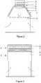
- illustrates schematically, in cross-sectional view, the configuration of one proposed embodiment of hybrid dephlegmator according to the first variation of the invention;
- Figure 3
- is a schematic side view thereof;
- Figure 4
- illustrates schematically, in side view, the configuration of one embodiment of tube bundle for use in a hybrid dephlegmator according to the invention;
- Figure 5
- illustrates schematically in cross-section the relative positioning of tubes in two adjacent rows;
- Figure 6
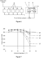
- is a flow diagram of the steam leaving a steam turbine and entering an A-frame condenser installation having a dephlegmator assembly according to the invention;
- Figure 7
- is a comparative graph showing the power output associated with four different configurations of condenser units; and,
- Figure 8
- is a view similar to
Figure 2 of an embodiment of the second variation of the invention. - In the embodiment of the invention illustrated in
Figures 2 to 5 of the drawings, a dephlegmator (1) according to the invention is incorporated into an existing A-frame type of air-cooled (dry) condenser installation comprising multiple primary condensers (2) in what is generally a usual arrangement. - The dephlegmator itself forms a terminal unit in the flow path of the spent steam emerging from a steam turbine operated electrical energy generating facility and, as more clearly illustrated in
Figures 2 and 3 , conforms to the present invention. - The dephlegmator thus comprises two stages connected in series wherein a first stage (3) is of generally conventional air-cooled reflux condenser construction consisting of multiple inclined finned tubes (4) that are similar to those used in a dry A-frame configuration although, if specially made for the purpose, they may be somewhat shorter. One or more fans (5) located in the region of the lower ends of the inclined finned tubes may be provided for inducing a draught through the tubes.
- The second stage (6) of the dephlegmator includes a generally horizontal tube bundle of smooth galvanised tubes (7) with a water deluge spray facility (8) located above the bundle of tubes and a water collection facility in the form of collection troughs (9) located beneath the tube bundle for collecting run-off water and enabling recycling of excess deluge water.
- The second stage can be operated selectively in either an air-cooled (dry) mode under selected ambient conditions or in a wet evaporatively cooled mode under other selected ambient conditions including, especially, elevated ambient temperature.
- Referring now more particularly to
Figures 4 and 5 of the drawings, it has been found that a particular arrangement of tube bundle operates particularly well to enhance the thermal performance of the delugeable tube bundle and ensure that the non-condensable gases are evacuated effectively from the tubes. In order to achieve this, the tube bundle is provided with three tube passes comprising a first group of tubes; a second group of tubes; and a third group of tubes. In this particular instance, the entire tube bundle has 25 horizontal rows of tubes spaced apart vertically. - The first group of tubes (11) that is indicated by a dotted envelope (X) in
Figure 4 has 20 rows in it and is located uppermost. The second group of tubes (12) that is indicated by a dotted envelope (Y) has 4 rows of tubes in it and is located immediately below the first group of tubes. The third group of tubes (13) that is indicated by dotted envelope (Z) has 1 row of tubes in it and is located lowermost. - In all cases, and as shown schematically in
Figure 5 the tubes in a row are spaced apart by approximately the outer diameter of the tubes themselves and the tubes in one row are offset from tubes in an adjacent row by a distance equal to the outer diameter of a tube so that water falling between two tubes of one row will fall on the tubes of the next row. - All of the tubes are slightly inclined to the horizontal along their length such that their outlet ends are somewhat lower than their inlet ends simply to ensure effective drainage of condensation towards the ultimate outlet end of the third group of tubes. The inclination need only be small and could, for example, be of the order of 50 mm with a tube length of 2.5 metres.
- The ends of the tubes are interconnected by providing a partition (15) in a large manifold chamber (16) communicating with the outlet ends (17) of all of the tubes of the first group; the inlet ends (18) of the tubes of the second group; and the outlet ends (19) of the tubes of the third group of tubes so as to divide off the outlet ends of the third group of tubes. The inlet ends (20) of the tubes of the first group of tubes are arranged to receive the inlet gases from the first stage of the dephlegmator.
- Communication between the outlet ends (21) of the second group of tubes and the inlet ends (22) of the third group of tubes is achieved by means of a relatively small manifold chamber (24) adjacent the inlet ends of the first group of tubes.
- The arrangement is such that the inlet gases pass through the first group of tubes into the large manifold chamber where they reverse direction and enter the inlet ends of the tubes of the second group of tubes. From the outlet ends of the second group of tubes the gases again reverse direction in order to pass into the inlet ends of the tubes of the third group of tubes.
- The non-condensable gases will ultimately be accumulated in the outlet header from where they can be evacuated by means of an ejector and the condensate will drain under the influence of gravity.
- The effective evacuation of non-condensibles, prevents sub-cooling of the condensate in the dephlegmator which would increase the absorption of oxygen into the condensate which could result in increased corrosion. Furthermore, subcooling could result in freezing of the condensate in winter thereby causing tube damage and finally requiring additional regenerative heating of the feedwater before it is returned to the boiler. Sub-cooling is therefore best avoided.
- It will be appreciated that during periods of low ambient temperatures in which air-cooling is sufficient, the second stage of the dephlegmator may be operated in a dry mode. However, during hotter periods, deluge water may be sprayed over the generally horizontal tube bundle so that it is then operated as an evaporative condenser.
- This system has the potential of enhanced thermal performance during periods of high ambient temperatures, while having a lower overall water consumption rate than in the instance of adiabatic pre-cooling of inlet air using a water spray whilst giving the same performance enhancement.
- It is to be noted that the finned tubes of the unit remain dry thereby reducing the risk of corrosion as well as scaling while the galvanized wetted plain tube surfaces of the tube bundle may be rinsed with clean water on a regular scheduled basis to minimize fouling.
- Initial comparative test results are shown in
Figure 7 in which the power output in megawatts of a test facility is plotted against the ambient temperature in degrees centigrade. The curve indicated by the letter "A" relates to a prior art three street dry A-frame condenser installation; the curve indicated by the letter "B" relates to a prior art four street dry A-frame condenser installation; the curve indicated by the letter "C" relates to a three street condenser assembly including a dephlegmator according to the invention operated in the wet mode; and, the curve indicated by the letter "D" relates to a three street condenser assembly including a dephlegmator according to the invention operated in the dry mode. - It will be noted that by utilising evaporative cooling in a dephlegmator as provided by the present invention, the power output of a power generating facility can be increased significantly during hot periods, thereby increasing revenues and power plant efficiency
- The cooling system according to the invention may use existing A-frame air-cooled condenser technology and through the introduction of a hybrid (dry or wet) dephlegmator there is achieved a measurable enhancement in cooling performance during higher ambient temperatures. During these periods the hybrid (dry or wet) condenser operating in a wet mode can achieve the same increased turbine performance as an oversized air-cooled condenser or an air-cooled condenser with adiabatic cooling (spray cooling) of the inlet air, but at a considerably lower cost. For the same turbine power output the water consumed by an air-cooled condenser incorporating a hybrid (dry or wet) dephlegmator is measurably less than an air-cooled condenser with adiabatic cooling of the inlet air.
- It will be understood that in one implementation of the invention as applied to existing installations, only the dephlegmators need to be modified thereby enabling existing air-cooled steam condensers to be retrofitted.
- Of course the invention can be applied to arrangements other than those of a standard A-frame configuration and
Figure 8 illustrates one alternative arrangement. In that arrangement two series of finned condenser tubes (31) are inclined downwardly towards each other in a type of inverted A-frame configuration with the tube bundle (32) being arranged between their lower ends at a suitable position along the length the condenser arrangement. An arrangement of spray nozzles (33) is supported above the tube bundle and drift eliminators (34) are located above the spray nozzles in order to capture at least some of any spray that may escape upwards. One or more fans (35) for inducing a draught through the finned condenser tubes and past the tube bundle can, in this instance, conveniently be located in the region of the upper ends of the finned condenser tubes. - Whatever construction is used, it is estimated that the capital cost of the hybrid (dry or wet) dephlegmator according to the invention will be only slightly more than that of a standard A-frame air-cooled dephlegmator.
- Numerous variations to what is described above may be made within the scope of the invention as defined in the claims.
Claims (13)
- A dephlegmator comprising two stages wherein a first stage includes an air-cooled reflux condenser (3) and wherein a second stage (6) includes a generally horizontal tube bundle of smooth or finned tubes that can be operated selectively in either an air-cooled dry mode under selected ambient conditions or in a wet evaporatively cooled mode under other selected ambient conditions including that of elevated ambient temperature, wherein the tube bundle comprises at least three groups of tubes comprising
a first group of tubes (11) that have inlet ends and outlet ends, characterized in that the at least three groups comprise a second group of tubes (12) that have inlet ends in communication with the outlet ends of the tubes of the first group thereof, the tubes of the second group also having outlet ends,
wherein the second group of tubes comprises from 15% to 30% of the number of tubes in the first group of tubes, and
wherein the tube bundle has a third group of tubes (13) wherein the tubes of the third group have inlet ends communicating with the outlet ends of the tubes of the second group thereof and
wherein the number of tubes in the third group of tubes is about one third to one quarter of the number of tubes in the second group of tubes . - A dephlegmator as claimed in claim 1 in which an arrangement of spray nozzles (8) is installed above the tube bundle whereby water can be sprayed onto the tube bundle in order to provide the evaporatively cooled mode.
- A dephlegmator as claimed in either one of claims 1 or 2 in which a drift eliminator (34) is positioned above the arrangement of spray nozzles to inhibit loss of water in the form of airborne droplets.
- A dephlegmator as claimed in any one of the preceding claims in which one or more collection troughs are provided beneath the tube bundle for collecting run-off water and enabling recycling of excess deluge water.
- A dephlegmator as claimed in any one of the preceding claims in which the first group of tubes is located vertically above the second group of tubes that is located vertically above the third group of tubes.
- A dephlegmator as claimed in any one of the preceding claims in which the first and second group of tubes are grouped at their ends that are in communication by providing a manifold chamber communicating with the outlet ends of all of the tubes of the first group and the inlet ends of the tubes of the second group, with a partition so as to divide off the outlet ends of the third group of tubes.
- A dephlegmator as claimed in any one of the preceding claims in which the outlet ends of the tubes of the second group open into a manifold chamber with which the inlet ends of the tubes of the third group of tubes communicate.
- A dephlegmator as claimed in any one of the preceding claims in which the first stage is an A-frame air cooled condenser arrangement in which multiple finned tubes extend upwards from two opposite sides to create an A-frame structure and the second stage tube bundle is positioned at the top of the condenser arrangement.
- A dephlegmator as claimed in any one of claims 1 to 7 in which the air cooled reflux condenser comprises multiple finned tubes extending downwards at the incline towards each other in an inverted A-frame type of arrangement in which instance the tube bundle is located at the lower ends of the finned tubes.
- A dephlegmator as claimed in any one of the preceding claims in which the tubes are inclined towards their outlet ends to provide for condensate drainage towards the outlet ends.
- A dephlegmator as claimed in any one of the preceding claims in which the tubes are arranged in generally horizontal rows thereof with the tubes of one row being offset from the tubes in a vertically adjacent row by one half of the spacing between the tubes.
- A dephlegmator as claimed in any one of the preceding claims in which the tube bundle includes multiple rows of parallel generally horizontal tubes arranged in a generally rectangular array, with each of the first, second and third groups of tubes comprising a number of generally horizontal rows of parallel tubes, and wherein the third group of tubes is disposed in one generally horizontal row.
- A dephlegmator as claimed in any one of the preceding claims in which the dephlegmator further comprises an outlet header at outlet ends of the tubes of the third group from where non-condensable gases can be evacuated by means of an ejector and condensate drains under the influence of gravity.
Applications Claiming Priority (3)
| Application Number | Priority Date | Filing Date | Title |
|---|---|---|---|
| ZA201105232 | 2011-07-15 | ||
| ZA201108738 | 2011-11-29 | ||
| PCT/IB2012/053511 WO2013011414A1 (en) | 2011-07-15 | 2012-07-10 | Dephlegmator |
Publications (2)
| Publication Number | Publication Date |
|---|---|
| EP2732229A1 EP2732229A1 (en) | 2014-05-21 |
| EP2732229B1 true EP2732229B1 (en) | 2020-07-08 |
Family
ID=46727272
Family Applications (1)
| Application Number | Title | Priority Date | Filing Date |
|---|---|---|---|
| EP12750817.4A Active EP2732229B1 (en) | 2011-07-15 | 2012-07-10 | Dephlegmator |
Country Status (8)
| Country | Link |
|---|---|
| US (1) | US10315128B2 (en) |
| EP (1) | EP2732229B1 (en) |
| JP (1) | JP6240597B2 (en) |
| CN (1) | CN103827619B (en) |
| BR (1) | BR112014000879A2 (en) |
| CA (1) | CA2842020A1 (en) |
| RU (1) | RU2598504C2 (en) |
| WO (1) | WO2013011414A1 (en) |
Families Citing this family (17)
| Publication number | Priority date | Publication date | Assignee | Title |
|---|---|---|---|---|
| US9551532B2 (en) | 2012-05-23 | 2017-01-24 | Spx Dry Cooling Usa Llc | Modular air cooled condenser apparatus and method |
| US20140202151A1 (en) * | 2013-01-21 | 2014-07-24 | Alliance For Sustainable Energy, Llc | Hybrid Air-Cooled Condenser For Power Plants and Other Applications |
| WO2016169076A1 (en) * | 2015-04-23 | 2016-10-27 | 赵元宾 | Column type cooling tube bundle with wedge-shaped gap |
| US10132568B2 (en) * | 2015-08-20 | 2018-11-20 | Holtec International | Dry cooling system for powerplants |
| WO2017202730A1 (en) | 2016-05-25 | 2017-11-30 | Spx Dry Cooling Belgium | Air-cooled condenser apparatus and method |
| RU2734089C2 (en) * | 2016-06-21 | 2020-10-12 | Эвапко, Инк. | Industrial steam condenser with completely secondary air cooling |
| US10024600B2 (en) * | 2016-06-21 | 2018-07-17 | Evapco, Inc. | Mini-tube air cooled industrial steam condenser |
| CN105928379B (en) * | 2016-06-21 | 2017-11-17 | 金石包装(嘉兴)有限公司 | A kind of cooling tower |
| EP3287732B1 (en) * | 2016-08-24 | 2019-10-02 | SPG Dry Cooling Belgium | Induced draft air-cooled condenser |
| US11796255B2 (en) | 2017-02-24 | 2023-10-24 | Holtec International | Air-cooled condenser with deflection limiter beams |
| US11604030B2 (en) | 2017-09-27 | 2023-03-14 | Holtec International | Air-cooled condenser system |
| EP3688396B1 (en) | 2017-09-27 | 2023-07-26 | Holtec International | Air-cooled condenser system |
| DE102017130807A1 (en) | 2017-12-20 | 2019-06-27 | Enexio Germany Gmbh | Air-cooled condenser system |
| WO2020257598A1 (en) * | 2019-06-19 | 2020-12-24 | Holtec International | Air-cooled condenser system |
| DK3792581T3 (en) * | 2019-09-13 | 2023-04-17 | Alfa Laval Corp Ab | PLATE HEAT EXCHANGER FOR TREATMENT OF A LIQUID SUPPLY |
| RU196300U1 (en) * | 2019-12-23 | 2020-02-25 | Федеральное государственное бюджетное образовательное учреждение высшего образования "Волгоградский государственный технический университет" (ВолгГТУ) | Dephlegmator |
| CN111637762B (en) * | 2020-05-07 | 2025-08-08 | 中国大唐集团科学技术研究院有限公司火力发电技术研究院 | Automatic control method and system for air-cooled condenser fan |
Citations (1)
| Publication number | Priority date | Publication date | Assignee | Title |
|---|---|---|---|---|
| JPS5874102A (en) * | 1981-10-29 | 1983-05-04 | Agency Of Ind Science & Technol | Condenser |
Family Cites Families (17)
| Publication number | Priority date | Publication date | Assignee | Title |
|---|---|---|---|---|
| GB485972A (en) | 1936-09-25 | 1938-05-27 | Krupp Ag | An improved method of and apparatus for condensing vapours, in particular the exhaust steam of locomotives, particularly turbine locomotives |
| US2401918A (en) | 1944-07-25 | 1946-06-11 | American Locomotive Co | Air-cooled heat exchanger |
| GB900949A (en) | 1958-10-27 | 1962-07-11 | Happel Gmbh | Air and water cooled heat exchanger |
| DE1451131B1 (en) | 1964-02-28 | 1970-07-30 | Gea Luftkuehler Happel Gmbh | Air-cooled surface condenser |
| BE754580A (en) * | 1969-08-08 | 1971-01-18 | Balcke Maschbau Ag | PROCESS FOR THE OPERATION OF A DRY REFRIGERATION TOWER UNDER HIGH AIR TEMPERATURES |
| IL37225A (en) * | 1971-07-05 | 1974-05-16 | Israel Desalination Eng Ltd | Multieffect evaporator |
| US4022853A (en) | 1974-10-30 | 1977-05-10 | Gea Luftkuhlergesellschaft Happel Gmbh & Co. Kg | Installation for changing the temperature of fluid media, particularly for cooling liquids and condensing vapors with air |
| US4417619A (en) * | 1978-06-05 | 1983-11-29 | Sasakura Engineering Co., Ltd. | Air-cooled heat exchanger |
| CN85101371A (en) * | 1985-04-01 | 1987-01-10 | 海蒙·索贝尔公司 | Condensator cooled by intense ventilation |
| SU1672187A1 (en) * | 1989-09-27 | 1991-08-23 | Всесоюзный государственный научно-исследовательский и проектно-изыскательский институт "Теплоэлектропроект" | Cooling unit |
| US5139083A (en) * | 1990-10-10 | 1992-08-18 | Larinoff Michael W | Air cooled vacuum steam condenser with flow-equalized mini-bundles |
| EP0794401A3 (en) | 1996-03-06 | 1998-09-23 | Hudson Products Corporation | Steam condensing apparatus |
| JP2002205535A (en) * | 2001-01-09 | 2002-07-23 | Japan Climate Systems Corp | Automotive condenser |
| JP2005241237A (en) * | 2004-01-27 | 2005-09-08 | Showa Denko Kk | Condenser and heat exchanger |
| CN200979376Y (en) * | 2005-09-19 | 2007-11-21 | 国电龙源电力技术工程有限责任公司 | A direct vacuum brazing plate-fin air-cooling condenser |
| WO2011056412A2 (en) * | 2009-11-04 | 2011-05-12 | Evapco, Inc. | Hybrid heat exchange apparatus |
| CN102003888B (en) * | 2010-11-19 | 2013-03-27 | 华北电力大学(保定) | Optimization method of spraying humidification system of direct air condenser |
-
2012
- 2012-07-10 BR BR112014000879A patent/BR112014000879A2/en not_active IP Right Cessation
- 2012-07-10 CA CA2842020A patent/CA2842020A1/en not_active Abandoned
- 2012-07-10 RU RU2014105309/06A patent/RU2598504C2/en not_active IP Right Cessation
- 2012-07-10 JP JP2014519670A patent/JP6240597B2/en not_active Expired - Fee Related
- 2012-07-10 US US14/232,813 patent/US10315128B2/en active Active
- 2012-07-10 EP EP12750817.4A patent/EP2732229B1/en active Active
- 2012-07-10 CN CN201280035237.2A patent/CN103827619B/en not_active Expired - Fee Related
- 2012-07-10 WO PCT/IB2012/053511 patent/WO2013011414A1/en not_active Ceased
Patent Citations (1)
| Publication number | Priority date | Publication date | Assignee | Title |
|---|---|---|---|---|
| JPS5874102A (en) * | 1981-10-29 | 1983-05-04 | Agency Of Ind Science & Technol | Condenser |
Non-Patent Citations (1)
| Title |
|---|
| JOHAN ADAM HEYNS ET AL: "Performance characteristics of an air-cooled steam condenser incorporating a hybrid (dry/wet) dephlegmator", 1 December 2008 (2008-12-01), XP055343163, Retrieved from the Internet <URL:http://scholar.sun.ac.za/bitstream/handle/10019.1/350/heyns_performance_2008.pdf?sequence=3&isAllowed=y> * |
Also Published As
| Publication number | Publication date |
|---|---|
| JP2014521048A (en) | 2014-08-25 |
| RU2014105309A (en) | 2015-08-27 |
| CA2842020A1 (en) | 2013-01-24 |
| CN103827619B (en) | 2016-11-16 |
| RU2598504C2 (en) | 2016-09-27 |
| BR112014000879A2 (en) | 2017-02-21 |
| JP6240597B2 (en) | 2017-11-29 |
| US20140367243A1 (en) | 2014-12-18 |
| US10315128B2 (en) | 2019-06-11 |
| WO2013011414A1 (en) | 2013-01-24 |
| EP2732229A1 (en) | 2014-05-21 |
| CN103827619A (en) | 2014-05-28 |
Similar Documents
| Publication | Publication Date | Title |
|---|---|---|
| US10315128B2 (en) | Dephlegmator | |
| US11112180B2 (en) | Modular air cooled condenser apparatus and method | |
| RU2734089C2 (en) | Industrial steam condenser with completely secondary air cooling | |
| RU2515324C2 (en) | Condenser of steam with air cooling and natural circulation, and also method | |
| US8297344B2 (en) | Modular air-cooled condenser apparatus and method | |
| CN202582241U (en) | WFE (Water Film Evaporation) peak condensing system connected with direct air cooling system in parallel | |
| CN101256043A (en) | Plate and shell unsaturated evaporation and condensation equipment | |
| JP6309351B2 (en) | Air-cooled steam condensing device | |
| CA2199209A1 (en) | Steam condensing apparatus | |
| US5787970A (en) | Air-cooled vacuum steam condenser with mixed flow bundle | |
| CN107270736B (en) | Evaporation-cooling decoupling type heat exchange device | |
| JP2710225B2 (en) | Heat exchanger for condenser | |
| WO2024186291A1 (en) | A condenser with a fin structure with an improved water accumulation feature | |
| CN216712058U (en) | Air-cooling and water-cooling integrated wine steam condensing system | |
| Guan et al. | Dry cooling towers for geothermal power plants | |
| HK1196153A (en) | Dephlegmator | |
| Poullikkas et al. | An overview of CSP cooling systems | |
| RU2850487C2 (en) | Air-cooled steam condenser with improved second-stage condenser | |
| CN207163257U (en) | One kind evaporation cooling decoupling type heat-exchanger rig | |
| US8689443B1 (en) | Method and apparatus to improve performance of power plant steam surface condensers | |
| US8707557B1 (en) | Method and apparatus to improve performance of power plant steam surface condensers | |
| Guan et al. | DRY POWER COOLING PLANTS TOWERS FOR GEOTHERMAL | |
| RU2489661C1 (en) | Double-stage condenser | |
| RU2246672C1 (en) | Multirow device for water vapor condensation in vacuum | |
| CN204594269U (en) | Light pipe sleeve pipe tube bank subtend admission composite condensation cooling tower |
Legal Events
| Date | Code | Title | Description |
|---|---|---|---|
| PUAI | Public reference made under article 153(3) epc to a published international application that has entered the european phase |
Free format text: ORIGINAL CODE: 0009012 |
|
| 17P | Request for examination filed |
Effective date: 20140213 |
|
| AK | Designated contracting states |
Kind code of ref document: A1 Designated state(s): AL AT BE BG CH CY CZ DE DK EE ES FI FR GB GR HR HU IE IS IT LI LT LU LV MC MK MT NL NO PL PT RO RS SE SI SK SM TR |
|
| DAX | Request for extension of the european patent (deleted) | ||
| RIN1 | Information on inventor provided before grant (corrected) |
Inventor name: REUTER, HANNO CARL RUDOLF Inventor name: KROEGER, DETLEV G. |
|
| STAA | Information on the status of an ep patent application or granted ep patent |
Free format text: STATUS: EXAMINATION IS IN PROGRESS |
|
| 17Q | First examination report despatched |
Effective date: 20161019 |
|
| GRAP | Despatch of communication of intention to grant a patent |
Free format text: ORIGINAL CODE: EPIDOSNIGR1 |
|
| STAA | Information on the status of an ep patent application or granted ep patent |
Free format text: STATUS: GRANT OF PATENT IS INTENDED |
|
| INTG | Intention to grant announced |
Effective date: 20200204 |
|
| GRAS | Grant fee paid |
Free format text: ORIGINAL CODE: EPIDOSNIGR3 |
|
| GRAA | (expected) grant |
Free format text: ORIGINAL CODE: 0009210 |
|
| STAA | Information on the status of an ep patent application or granted ep patent |
Free format text: STATUS: THE PATENT HAS BEEN GRANTED |
|
| AK | Designated contracting states |
Kind code of ref document: B1 Designated state(s): AL AT BE BG CH CY CZ DE DK EE ES FI FR GB GR HR HU IE IS IT LI LT LU LV MC MK MT NL NO PL PT RO RS SE SI SK SM TR |
|
| REG | Reference to a national code |
Ref country code: GB Ref legal event code: FG4D |
|
| REG | Reference to a national code |
Ref country code: CH Ref legal event code: EP Ref country code: AT Ref legal event code: REF Ref document number: 1288908 Country of ref document: AT Kind code of ref document: T Effective date: 20200715 |
|
| REG | Reference to a national code |
Ref country code: DE Ref legal event code: R096 Ref document number: 602012071147 Country of ref document: DE |
|
| REG | Reference to a national code |
Ref country code: IE Ref legal event code: FG4D |
|
| REG | Reference to a national code |
Ref country code: LT Ref legal event code: MG4D |
|
| REG | Reference to a national code |
Ref country code: AT Ref legal event code: MK05 Ref document number: 1288908 Country of ref document: AT Kind code of ref document: T Effective date: 20200708 |
|
| REG | Reference to a national code |
Ref country code: NL Ref legal event code: MP Effective date: 20200708 |
|
| PG25 | Lapsed in a contracting state [announced via postgrant information from national office to epo] |
Ref country code: LT Free format text: LAPSE BECAUSE OF FAILURE TO SUBMIT A TRANSLATION OF THE DESCRIPTION OR TO PAY THE FEE WITHIN THE PRESCRIBED TIME-LIMIT Effective date: 20200708 Ref country code: FI Free format text: LAPSE BECAUSE OF FAILURE TO SUBMIT A TRANSLATION OF THE DESCRIPTION OR TO PAY THE FEE WITHIN THE PRESCRIBED TIME-LIMIT Effective date: 20200708 Ref country code: PT Free format text: LAPSE BECAUSE OF FAILURE TO SUBMIT A TRANSLATION OF THE DESCRIPTION OR TO PAY THE FEE WITHIN THE PRESCRIBED TIME-LIMIT Effective date: 20201109 Ref country code: BG Free format text: LAPSE BECAUSE OF FAILURE TO SUBMIT A TRANSLATION OF THE DESCRIPTION OR TO PAY THE FEE WITHIN THE PRESCRIBED TIME-LIMIT Effective date: 20201008 Ref country code: SE Free format text: LAPSE BECAUSE OF FAILURE TO SUBMIT A TRANSLATION OF THE DESCRIPTION OR TO PAY THE FEE WITHIN THE PRESCRIBED TIME-LIMIT Effective date: 20200708 Ref country code: ES Free format text: LAPSE BECAUSE OF FAILURE TO SUBMIT A TRANSLATION OF THE DESCRIPTION OR TO PAY THE FEE WITHIN THE PRESCRIBED TIME-LIMIT Effective date: 20200708 Ref country code: HR Free format text: LAPSE BECAUSE OF FAILURE TO SUBMIT A TRANSLATION OF THE DESCRIPTION OR TO PAY THE FEE WITHIN THE PRESCRIBED TIME-LIMIT Effective date: 20200708 Ref country code: AT Free format text: LAPSE BECAUSE OF FAILURE TO SUBMIT A TRANSLATION OF THE DESCRIPTION OR TO PAY THE FEE WITHIN THE PRESCRIBED TIME-LIMIT Effective date: 20200708 Ref country code: GR Free format text: LAPSE BECAUSE OF FAILURE TO SUBMIT A TRANSLATION OF THE DESCRIPTION OR TO PAY THE FEE WITHIN THE PRESCRIBED TIME-LIMIT Effective date: 20201009 Ref country code: NO Free format text: LAPSE BECAUSE OF FAILURE TO SUBMIT A TRANSLATION OF THE DESCRIPTION OR TO PAY THE FEE WITHIN THE PRESCRIBED TIME-LIMIT Effective date: 20201008 |
|
| PGFP | Annual fee paid to national office [announced via postgrant information from national office to epo] |
Ref country code: GB Payment date: 20201006 Year of fee payment: 9 |
|
| PG25 | Lapsed in a contracting state [announced via postgrant information from national office to epo] |
Ref country code: PL Free format text: LAPSE BECAUSE OF FAILURE TO SUBMIT A TRANSLATION OF THE DESCRIPTION OR TO PAY THE FEE WITHIN THE PRESCRIBED TIME-LIMIT Effective date: 20200708 Ref country code: RS Free format text: LAPSE BECAUSE OF FAILURE TO SUBMIT A TRANSLATION OF THE DESCRIPTION OR TO PAY THE FEE WITHIN THE PRESCRIBED TIME-LIMIT Effective date: 20200708 Ref country code: LV Free format text: LAPSE BECAUSE OF FAILURE TO SUBMIT A TRANSLATION OF THE DESCRIPTION OR TO PAY THE FEE WITHIN THE PRESCRIBED TIME-LIMIT Effective date: 20200708 Ref country code: IS Free format text: LAPSE BECAUSE OF FAILURE TO SUBMIT A TRANSLATION OF THE DESCRIPTION OR TO PAY THE FEE WITHIN THE PRESCRIBED TIME-LIMIT Effective date: 20201108 |
|
| REG | Reference to a national code |
Ref country code: CH Ref legal event code: PL |
|
| PG25 | Lapsed in a contracting state [announced via postgrant information from national office to epo] |
Ref country code: NL Free format text: LAPSE BECAUSE OF FAILURE TO SUBMIT A TRANSLATION OF THE DESCRIPTION OR TO PAY THE FEE WITHIN THE PRESCRIBED TIME-LIMIT Effective date: 20200708 |
|
| REG | Reference to a national code |
Ref country code: DE Ref legal event code: R097 Ref document number: 602012071147 Country of ref document: DE |
|
| REG | Reference to a national code |
Ref country code: BE Ref legal event code: MM Effective date: 20200731 |
|
| PG25 | Lapsed in a contracting state [announced via postgrant information from national office to epo] |
Ref country code: RO Free format text: LAPSE BECAUSE OF FAILURE TO SUBMIT A TRANSLATION OF THE DESCRIPTION OR TO PAY THE FEE WITHIN THE PRESCRIBED TIME-LIMIT Effective date: 20200708 Ref country code: SM Free format text: LAPSE BECAUSE OF FAILURE TO SUBMIT A TRANSLATION OF THE DESCRIPTION OR TO PAY THE FEE WITHIN THE PRESCRIBED TIME-LIMIT Effective date: 20200708 Ref country code: LU Free format text: LAPSE BECAUSE OF NON-PAYMENT OF DUE FEES Effective date: 20200710 Ref country code: MC Free format text: LAPSE BECAUSE OF FAILURE TO SUBMIT A TRANSLATION OF THE DESCRIPTION OR TO PAY THE FEE WITHIN THE PRESCRIBED TIME-LIMIT Effective date: 20200708 Ref country code: CZ Free format text: LAPSE BECAUSE OF FAILURE TO SUBMIT A TRANSLATION OF THE DESCRIPTION OR TO PAY THE FEE WITHIN THE PRESCRIBED TIME-LIMIT Effective date: 20200708 Ref country code: DK Free format text: LAPSE BECAUSE OF FAILURE TO SUBMIT A TRANSLATION OF THE DESCRIPTION OR TO PAY THE FEE WITHIN THE PRESCRIBED TIME-LIMIT Effective date: 20200708 Ref country code: CH Free format text: LAPSE BECAUSE OF NON-PAYMENT OF DUE FEES Effective date: 20200731 Ref country code: EE Free format text: LAPSE BECAUSE OF FAILURE TO SUBMIT A TRANSLATION OF THE DESCRIPTION OR TO PAY THE FEE WITHIN THE PRESCRIBED TIME-LIMIT Effective date: 20200708 Ref country code: LI Free format text: LAPSE BECAUSE OF NON-PAYMENT OF DUE FEES Effective date: 20200731 Ref country code: IT Free format text: LAPSE BECAUSE OF FAILURE TO SUBMIT A TRANSLATION OF THE DESCRIPTION OR TO PAY THE FEE WITHIN THE PRESCRIBED TIME-LIMIT Effective date: 20200708 |
|
| PLBE | No opposition filed within time limit |
Free format text: ORIGINAL CODE: 0009261 |
|
| STAA | Information on the status of an ep patent application or granted ep patent |
Free format text: STATUS: NO OPPOSITION FILED WITHIN TIME LIMIT |
|
| PG25 | Lapsed in a contracting state [announced via postgrant information from national office to epo] |
Ref country code: AL Free format text: LAPSE BECAUSE OF FAILURE TO SUBMIT A TRANSLATION OF THE DESCRIPTION OR TO PAY THE FEE WITHIN THE PRESCRIBED TIME-LIMIT Effective date: 20200708 Ref country code: BE Free format text: LAPSE BECAUSE OF NON-PAYMENT OF DUE FEES Effective date: 20200731 |
|
| 26N | No opposition filed |
Effective date: 20210409 |
|
| PG25 | Lapsed in a contracting state [announced via postgrant information from national office to epo] |
Ref country code: SK Free format text: LAPSE BECAUSE OF FAILURE TO SUBMIT A TRANSLATION OF THE DESCRIPTION OR TO PAY THE FEE WITHIN THE PRESCRIBED TIME-LIMIT Effective date: 20200708 |
|
| PG25 | Lapsed in a contracting state [announced via postgrant information from national office to epo] |
Ref country code: FR Free format text: LAPSE BECAUSE OF NON-PAYMENT OF DUE FEES Effective date: 20200908 |
|
| PG25 | Lapsed in a contracting state [announced via postgrant information from national office to epo] |
Ref country code: IE Free format text: LAPSE BECAUSE OF NON-PAYMENT OF DUE FEES Effective date: 20200710 Ref country code: SI Free format text: LAPSE BECAUSE OF FAILURE TO SUBMIT A TRANSLATION OF THE DESCRIPTION OR TO PAY THE FEE WITHIN THE PRESCRIBED TIME-LIMIT Effective date: 20200708 |
|
| PGFP | Annual fee paid to national office [announced via postgrant information from national office to epo] |
Ref country code: DE Payment date: 20210721 Year of fee payment: 10 |
|
| GBPC | Gb: european patent ceased through non-payment of renewal fee |
Effective date: 20210710 |
|
| PG25 | Lapsed in a contracting state [announced via postgrant information from national office to epo] |
Ref country code: GB Free format text: LAPSE BECAUSE OF NON-PAYMENT OF DUE FEES Effective date: 20210710 |
|
| PG25 | Lapsed in a contracting state [announced via postgrant information from national office to epo] |
Ref country code: TR Free format text: LAPSE BECAUSE OF FAILURE TO SUBMIT A TRANSLATION OF THE DESCRIPTION OR TO PAY THE FEE WITHIN THE PRESCRIBED TIME-LIMIT Effective date: 20200708 Ref country code: MT Free format text: LAPSE BECAUSE OF FAILURE TO SUBMIT A TRANSLATION OF THE DESCRIPTION OR TO PAY THE FEE WITHIN THE PRESCRIBED TIME-LIMIT Effective date: 20200708 Ref country code: CY Free format text: LAPSE BECAUSE OF FAILURE TO SUBMIT A TRANSLATION OF THE DESCRIPTION OR TO PAY THE FEE WITHIN THE PRESCRIBED TIME-LIMIT Effective date: 20200708 |
|
| PG25 | Lapsed in a contracting state [announced via postgrant information from national office to epo] |
Ref country code: MK Free format text: LAPSE BECAUSE OF FAILURE TO SUBMIT A TRANSLATION OF THE DESCRIPTION OR TO PAY THE FEE WITHIN THE PRESCRIBED TIME-LIMIT Effective date: 20200708 |
|
| REG | Reference to a national code |
Ref country code: DE Ref legal event code: R119 Ref document number: 602012071147 Country of ref document: DE |
|
| PG25 | Lapsed in a contracting state [announced via postgrant information from national office to epo] |
Ref country code: DE Free format text: LAPSE BECAUSE OF NON-PAYMENT OF DUE FEES Effective date: 20230201 |