EP2731784B1 - Cell including clean and dirty sections for fabricating composite parts - Google Patents
Cell including clean and dirty sections for fabricating composite parts Download PDFInfo
- Publication number
- EP2731784B1 EP2731784B1 EP12741164.3A EP12741164A EP2731784B1 EP 2731784 B1 EP2731784 B1 EP 2731784B1 EP 12741164 A EP12741164 A EP 12741164A EP 2731784 B1 EP2731784 B1 EP 2731784B1
- Authority
- EP
- European Patent Office
- Prior art keywords
- section
- clean
- dirty
- end effector
- positioning system
- Prior art date
- Legal status (The legal status is an assumption and is not a legal conclusion. Google has not performed a legal analysis and makes no representation as to the accuracy of the status listed.)
- Active
Links
- 239000002131 composite material Substances 0.000 title claims description 61
- 239000012636 effector Substances 0.000 claims description 87
- 238000004519 manufacturing process Methods 0.000 claims description 56
- 238000000034 method Methods 0.000 claims description 18
- 238000003754 machining Methods 0.000 claims description 12
- 239000000356 contaminant Substances 0.000 claims description 7
- 238000012545 processing Methods 0.000 claims description 6
- 239000012783 reinforcing fiber Substances 0.000 claims description 6
- 230000008569 process Effects 0.000 claims description 5
- 238000004140 cleaning Methods 0.000 claims description 4
- 239000002245 particle Substances 0.000 claims description 4
- 210000004027 cell Anatomy 0.000 description 33
- 230000008439 repair process Effects 0.000 description 13
- 239000000463 material Substances 0.000 description 11
- 238000007689 inspection Methods 0.000 description 9
- 238000013461 design Methods 0.000 description 8
- 239000000428 dust Substances 0.000 description 8
- 238000003801 milling Methods 0.000 description 7
- RTAQQCXQSZGOHL-UHFFFAOYSA-N Titanium Chemical compound [Ti] RTAQQCXQSZGOHL-UHFFFAOYSA-N 0.000 description 6
- 238000005520 cutting process Methods 0.000 description 6
- 238000005553 drilling Methods 0.000 description 6
- 239000004744 fabric Substances 0.000 description 6
- 239000006260 foam Substances 0.000 description 6
- 239000010936 titanium Substances 0.000 description 6
- 229910052719 titanium Inorganic materials 0.000 description 6
- 238000012546 transfer Methods 0.000 description 6
- 238000009966 trimming Methods 0.000 description 6
- 239000000945 filler Substances 0.000 description 5
- 238000004088 simulation Methods 0.000 description 5
- 210000003850 cellular structure Anatomy 0.000 description 4
- 239000000835 fiber Substances 0.000 description 4
- 238000010422 painting Methods 0.000 description 4
- 239000003351 stiffener Substances 0.000 description 4
- 230000000712 assembly Effects 0.000 description 3
- 238000000429 assembly Methods 0.000 description 3
- 238000009727 automated fiber placement Methods 0.000 description 3
- 230000008901 benefit Effects 0.000 description 3
- 230000008859 change Effects 0.000 description 3
- 238000001802 infusion Methods 0.000 description 3
- 238000009434 installation Methods 0.000 description 3
- 239000011347 resin Substances 0.000 description 3
- 229920005989 resin Polymers 0.000 description 3
- 239000000523 sample Substances 0.000 description 3
- 229920000049 Carbon (fiber) Polymers 0.000 description 2
- 239000004593 Epoxy Substances 0.000 description 2
- 230000004888 barrier function Effects 0.000 description 2
- 239000004917 carbon fiber Substances 0.000 description 2
- 239000004918 carbon fiber reinforced polymer Substances 0.000 description 2
- 238000005056 compaction Methods 0.000 description 2
- 230000008878 coupling Effects 0.000 description 2
- 238000010168 coupling process Methods 0.000 description 2
- 238000005859 coupling reaction Methods 0.000 description 2
- 230000001066 destructive effect Effects 0.000 description 2
- 230000007613 environmental effect Effects 0.000 description 2
- 210000000569 greater omentum Anatomy 0.000 description 2
- 238000009787 hand lay-up Methods 0.000 description 2
- 239000011159 matrix material Substances 0.000 description 2
- 229910052751 metal Inorganic materials 0.000 description 2
- 239000002184 metal Substances 0.000 description 2
- 239000004033 plastic Substances 0.000 description 2
- 229920003023 plastic Polymers 0.000 description 2
- 230000001681 protective effect Effects 0.000 description 2
- 239000007921 spray Substances 0.000 description 2
- XLYOFNOQVPJJNP-UHFFFAOYSA-N water Substances O XLYOFNOQVPJJNP-UHFFFAOYSA-N 0.000 description 2
- 241000238631 Hexapoda Species 0.000 description 1
- 239000004698 Polyethylene Substances 0.000 description 1
- 235000004443 Ricinus communis Nutrition 0.000 description 1
- 240000000528 Ricinus communis Species 0.000 description 1
- 230000001133 acceleration Effects 0.000 description 1
- 229910052782 aluminium Inorganic materials 0.000 description 1
- XAGFODPZIPBFFR-UHFFFAOYSA-N aluminium Chemical compound [Al] XAGFODPZIPBFFR-UHFFFAOYSA-N 0.000 description 1
- 230000003750 conditioning effect Effects 0.000 description 1
- 239000000470 constituent Substances 0.000 description 1
- 238000011109 contamination Methods 0.000 description 1
- 239000002826 coolant Substances 0.000 description 1
- 238000001914 filtration Methods 0.000 description 1
- 239000006261 foam material Substances 0.000 description 1
- 238000005470 impregnation Methods 0.000 description 1
- 238000003475 lamination Methods 0.000 description 1
- 239000007788 liquid Substances 0.000 description 1
- VNWKTOKETHGBQD-UHFFFAOYSA-N methane Chemical compound C VNWKTOKETHGBQD-UHFFFAOYSA-N 0.000 description 1
- 239000000203 mixture Substances 0.000 description 1
- 239000002991 molded plastic Substances 0.000 description 1
- 238000000465 moulding Methods 0.000 description 1
- 238000004806 packaging method and process Methods 0.000 description 1
- 239000003973 paint Substances 0.000 description 1
- -1 polyethylene Polymers 0.000 description 1
- 229920000573 polyethylene Polymers 0.000 description 1
- 229920000582 polyisocyanurate Polymers 0.000 description 1
- 239000011495 polyisocyanurate Substances 0.000 description 1
- 238000011417 postcuring Methods 0.000 description 1
- 230000002787 reinforcement Effects 0.000 description 1
- 238000007789 sealing Methods 0.000 description 1
- 230000003068 static effect Effects 0.000 description 1
- 230000007704 transition Effects 0.000 description 1
- 238000009423 ventilation Methods 0.000 description 1
- 238000012795 verification Methods 0.000 description 1
Images


Classifications
-
- B—PERFORMING OPERATIONS; TRANSPORTING
- B64—AIRCRAFT; AVIATION; COSMONAUTICS
- B64F—GROUND OR AIRCRAFT-CARRIER-DECK INSTALLATIONS SPECIALLY ADAPTED FOR USE IN CONNECTION WITH AIRCRAFT; DESIGNING, MANUFACTURING, ASSEMBLING, CLEANING, MAINTAINING OR REPAIRING AIRCRAFT, NOT OTHERWISE PROVIDED FOR; HANDLING, TRANSPORTING, TESTING OR INSPECTING AIRCRAFT COMPONENTS, NOT OTHERWISE PROVIDED FOR
- B64F5/00—Designing, manufacturing, assembling, cleaning, maintaining or repairing aircraft, not otherwise provided for; Handling, transporting, testing or inspecting aircraft components, not otherwise provided for
-
- B—PERFORMING OPERATIONS; TRANSPORTING
- B29—WORKING OF PLASTICS; WORKING OF SUBSTANCES IN A PLASTIC STATE IN GENERAL
- B29C—SHAPING OR JOINING OF PLASTICS; SHAPING OF MATERIAL IN A PLASTIC STATE, NOT OTHERWISE PROVIDED FOR; AFTER-TREATMENT OF THE SHAPED PRODUCTS, e.g. REPAIRING
- B29C73/00—Repairing of articles made from plastics or substances in a plastic state, e.g. of articles shaped or produced by using techniques covered by this subclass or subclass B29D
- B29C73/04—Repairing of articles made from plastics or substances in a plastic state, e.g. of articles shaped or produced by using techniques covered by this subclass or subclass B29D using preformed elements
-
- B—PERFORMING OPERATIONS; TRANSPORTING
- B29—WORKING OF PLASTICS; WORKING OF SUBSTANCES IN A PLASTIC STATE IN GENERAL
- B29C—SHAPING OR JOINING OF PLASTICS; SHAPING OF MATERIAL IN A PLASTIC STATE, NOT OTHERWISE PROVIDED FOR; AFTER-TREATMENT OF THE SHAPED PRODUCTS, e.g. REPAIRING
- B29C70/00—Shaping composites, i.e. plastics material comprising reinforcements, fillers or preformed parts, e.g. inserts
- B29C70/04—Shaping composites, i.e. plastics material comprising reinforcements, fillers or preformed parts, e.g. inserts comprising reinforcements only, e.g. self-reinforcing plastics
- B29C70/28—Shaping operations therefor
- B29C70/30—Shaping by lay-up, i.e. applying fibres, tape or broadsheet on a mould, former or core; Shaping by spray-up, i.e. spraying of fibres on a mould, former or core
-
- B—PERFORMING OPERATIONS; TRANSPORTING
- B64—AIRCRAFT; AVIATION; COSMONAUTICS
- B64C—AEROPLANES; HELICOPTERS
- B64C1/00—Fuselages; Constructional features common to fuselages, wings, stabilising surfaces or the like
-
- B—PERFORMING OPERATIONS; TRANSPORTING
- B29—WORKING OF PLASTICS; WORKING OF SUBSTANCES IN A PLASTIC STATE IN GENERAL
- B29C—SHAPING OR JOINING OF PLASTICS; SHAPING OF MATERIAL IN A PLASTIC STATE, NOT OTHERWISE PROVIDED FOR; AFTER-TREATMENT OF THE SHAPED PRODUCTS, e.g. REPAIRING
- B29C35/00—Heating, cooling or curing, e.g. crosslinking or vulcanising; Apparatus therefor
- B29C35/02—Heating or curing, e.g. crosslinking or vulcanizing during moulding, e.g. in a mould
- B29C35/0227—Heating or curing, e.g. crosslinking or vulcanizing during moulding, e.g. in a mould using pressure vessels, e.g. autoclaves, vulcanising pans
-
- B—PERFORMING OPERATIONS; TRANSPORTING
- B29—WORKING OF PLASTICS; WORKING OF SUBSTANCES IN A PLASTIC STATE IN GENERAL
- B29C—SHAPING OR JOINING OF PLASTICS; SHAPING OF MATERIAL IN A PLASTIC STATE, NOT OTHERWISE PROVIDED FOR; AFTER-TREATMENT OF THE SHAPED PRODUCTS, e.g. REPAIRING
- B29C70/00—Shaping composites, i.e. plastics material comprising reinforcements, fillers or preformed parts, e.g. inserts
- B29C70/04—Shaping composites, i.e. plastics material comprising reinforcements, fillers or preformed parts, e.g. inserts comprising reinforcements only, e.g. self-reinforcing plastics
- B29C70/28—Shaping operations therefor
- B29C70/30—Shaping by lay-up, i.e. applying fibres, tape or broadsheet on a mould, former or core; Shaping by spray-up, i.e. spraying of fibres on a mould, former or core
- B29C70/32—Shaping by lay-up, i.e. applying fibres, tape or broadsheet on a mould, former or core; Shaping by spray-up, i.e. spraying of fibres on a mould, former or core on a rotating mould, former or core
-
- Y—GENERAL TAGGING OF NEW TECHNOLOGICAL DEVELOPMENTS; GENERAL TAGGING OF CROSS-SECTIONAL TECHNOLOGIES SPANNING OVER SEVERAL SECTIONS OF THE IPC; TECHNICAL SUBJECTS COVERED BY FORMER USPC CROSS-REFERENCE ART COLLECTIONS [XRACs] AND DIGESTS
- Y02—TECHNOLOGIES OR APPLICATIONS FOR MITIGATION OR ADAPTATION AGAINST CLIMATE CHANGE
- Y02T—CLIMATE CHANGE MITIGATION TECHNOLOGIES RELATED TO TRANSPORTATION
- Y02T50/00—Aeronautics or air transport
- Y02T50/40—Weight reduction
-
- Y—GENERAL TAGGING OF NEW TECHNOLOGICAL DEVELOPMENTS; GENERAL TAGGING OF CROSS-SECTIONAL TECHNOLOGIES SPANNING OVER SEVERAL SECTIONS OF THE IPC; TECHNICAL SUBJECTS COVERED BY FORMER USPC CROSS-REFERENCE ART COLLECTIONS [XRACs] AND DIGESTS
- Y10—TECHNICAL SUBJECTS COVERED BY FORMER USPC
- Y10T—TECHNICAL SUBJECTS COVERED BY FORMER US CLASSIFICATION
- Y10T29/00—Metal working
- Y10T29/49—Method of mechanical manufacture
- Y10T29/49801—Shaping fiber or fibered material
-
- Y—GENERAL TAGGING OF NEW TECHNOLOGICAL DEVELOPMENTS; GENERAL TAGGING OF CROSS-SECTIONAL TECHNOLOGIES SPANNING OVER SEVERAL SECTIONS OF THE IPC; TECHNICAL SUBJECTS COVERED BY FORMER USPC CROSS-REFERENCE ART COLLECTIONS [XRACs] AND DIGESTS
- Y10—TECHNICAL SUBJECTS COVERED BY FORMER USPC
- Y10T—TECHNICAL SUBJECTS COVERED BY FORMER US CLASSIFICATION
- Y10T29/00—Metal working
- Y10T29/49—Method of mechanical manufacture
- Y10T29/49995—Shaping one-piece blank by removing material
-
- Y—GENERAL TAGGING OF NEW TECHNOLOGICAL DEVELOPMENTS; GENERAL TAGGING OF CROSS-SECTIONAL TECHNOLOGIES SPANNING OVER SEVERAL SECTIONS OF THE IPC; TECHNICAL SUBJECTS COVERED BY FORMER USPC CROSS-REFERENCE ART COLLECTIONS [XRACs] AND DIGESTS
- Y10—TECHNICAL SUBJECTS COVERED BY FORMER USPC
- Y10T—TECHNICAL SUBJECTS COVERED BY FORMER US CLASSIFICATION
- Y10T29/00—Metal working
- Y10T29/51—Plural diverse manufacturing apparatus including means for metal shaping or assembling
Definitions
- an aircraft's nose cab section may be damaged by a bird strike, a lower lobe may be damaged due to nose gear collapse, mid-section door surrounds may be damaged due to collisions with ground handling equipment, an end section lower lobe may be damaged by a tail strike, etc.
- a fuselage made up of several one-piece composite barrel sections.
- Each barrel section includes skin, hoop frames, and stiffeners (e.g., stringers).
- the stiffeners may be integrated with the skin (by co-curing during fabrication).
- the hoop frames may be mechanically fastened to the skin. If a large area of a fuselage section becomes damaged, removing and replacing the entire barrel section would be prohibitively expensive, disruptive to production, and time consuming.
- Document GB 2 116 594 A shows a clear room environment for manufacturing moulded plastics bodies, especially containers for the pharmaceutical industry, comprises at least two separate closed environments separated by a wall, one of them being kept at elevated pressure by filtered air.
- the wall has an opening in it and a moulding machine for making the containers protrudes through the opening and is sealed into it but is able to move into and out of the opening, for example on rails, with the services to the machine being connected to it in the one environment, whilst the bodies produced emerge from that part of the machine which, in use, is in the environment which is at an elevated pressure.
- Document US 5 341 918 A shows an article transfer device for transferring articles from a first position to a second position including a transfer screw, a conveying system, a stationary dead plate and a pressure adjustment wall.
- the screw is constructed from a flexible material and is essentially a continuous helical spiral having its ends connected to a support structure. Because of the flexible nature of the screw, different size articles can be transferred across the dead plate without having to change the screw.
- the article transfer device is useful in a clean room and less clean room application where articles need to be transferred between the rooms without returning any contaminants to the clean room. No individual part of the transfer device moves from the clean room to the less clean room and back again, thereby maintaining the sterile environment in the clean room.
- the pressure wall is adjusted so that the screw conforms to the different size articles and transfers the same. Lost production time and additional labor are eliminated as a result of the conforming nature of the article transfer device.
- Document US 2006/0180264 A1 shows a composite item fabricated with a device.
- the device includes an end effector and a positioning device.
- the end effector places a tow.
- the end effector includes a spindle, compaction device, and a path.
- the spindle detachably secures a spool of tow and the path is disposed from the spool to the compaction device.
- the positioning device positions the end effector.
- the end effector is detachably secured to the positioning device.
- a method is provided of using a fabrication all to a method of using a fabrication cell to fabricate a composite part, the fabrication cell comprising a clean section for performing clean operations including laying up the reinforcing fibers on a mandrel tool, the clean section satisfying clean room requirements for processing uncured composite materials; an adjacent dirty section for performing dirty operations including machining the layup after curing; a common end effector positioning system movable between the clean and dirty sections; and means for preventing contaminants in the dirty section from entering the clean section; the method comprising: using the end effector positioning system to build a mandrel tool in the dirty section; moving the mandrel tool and the end effector positioning system into the clean section; using the end effector positioning system to deposit reinforcing fibers on the tool; moving the tool to a curing section and performing curing; moving the mandrel tool and end the effector positioning system back into the dirty section; machining the cured part on the tool.
- a fabrication cell includes a clean section including interchangeable end effectors for performing composite layup operations.
- the clean section satisfies clean room requirements for processing uncured composite materials.
- the fabrication cell further includes a dirty section adjacent the clean section, the dirty section including interchangeable end effectors for performing machining operations; and an end effector positioning system, movable between the clean and dirty sections, for selecting and using the end effectors to perform the layup operations in the clean section and the machining operations in the dirty section.
- FIG. 1 illustrates a fabrication cell 110 for manufacturing a composite part including layers or plies of reinforcing fibers embedded in a matrix.
- CFRP carbon fiber reinforced plastic
- the constituents may include carbon fibers embedded in an epoxy matrix.
- the fabrication cell 110 includes a dirty section 120 and a clean section 130.
- Operations in the dirty section 120 include, but are not limited to, assembly and machining (e.g., trimming, milling and drilling). Operations are considered dirty if they can produce dust or contaminants that violate clean room requirements for the processing of uncured composite materials.
- the dirty section 120 may include a vacuum system 122 for minimizing dust and debris to facilitate cleaning.
- the vacuum system 122 may have up to 98% or greater effectiveness from removing dust.
- Operations in the clean section 130 include composite layup on a mandrel tool.
- fibers may be deposited on a layup mandrel tool that is static. In other embodiments, fibers may be deposited on a layup mandrel tool while the tool is being rotated.
- Operations in the clean section 130 further include caul plate installation, bagging, and material cutting.
- fabric for resin infusion or pre-impregnation could be cut by an ultrasonic knife or other device, such as a ply cutter or a hand tool. Resin infusion may also be performed in the clean section 130.
- the clean section 130 may include an air filtration and conditioning system 132 for maintaining environmental conditions within specification.
- composite facilities require 400,000 class clean rooms with temperature, humidity, and particle count monitored. The equipment and tooling should satisfy these requirements when moved from the dirty section 120 to the clean section 130. Should the clean section 130 fall out specification, wait time may be required for air circulation filters of the system 132 to remove dust from the air.
- the fabrication cell 110 includes a common end effector positioning system 140, movable between the dirty and clean sections 120 and 130, for performing all of these clean and dirty operations.
- the end effector positioning system 140 may use a plurality of interchangeable end effectors for performing the operations.
- the end effectors may be located at end effector stations 150 located in the dirty and clean sections 120 and 130.
- a manual, automatic, or semi automatic changer may be used to change end effectors in both dirty and clean sections 120 and 130.
- the end effectors may include tools for machining (e.g., milling, drilling), tools for trimming, a lamination head for tape or slit tape tow laydown of the panel or face sheet, a paint spray head for painting, an ultrasonic cutter for cutting prepreg or dry material, an NDI head (with necessary shoes) for ultrasonic inspection of the composite part, a stringer roll former for forming composite parts, a material dispenser, and inspection probes for geometric and dimensional inspection of the composite part.
- tools for machining e.g., milling, drilling
- tools for trimming e.g., a lamination head for tape or slit tape tow laydown of the panel or face sheet
- a paint spray head for painting
- an ultrasonic cutter for cutting prepreg or dry material
- an NDI head with necessary shoes
- the end effector positioning system 140 may include a single positioning machine such as a gantry 142 having multiple axes of motion (e.g., up to seven axes).
- the positioning system 140 may include a robot or multiple robots for performing the clean and dirty operations.
- a single robot may have interchangeable end effectors. Multiple robots may use combinations of dedicated end effectors.
- Other types of end effector positioning systems may include combinations of linear Cartesian axis platforms, rotary axis platforms, and Stewart platforms using parallel kinematics. Specific examples include gantries, robots, robots-on-rail, post-mill type platforms, and Stewart platforms (e.g. hexapods).
- the end effector positioning system 140 is configured to deliver a selected end effector to a position or along a path to perform its function, while satisfying performance requirements (e.g., angles, velocity, acceleration, stiffness, range of travel, utilities, quick-release coupling).
- performance requirements e.g., angles, velocity, acceleration, stiffness, range of travel, utilities, quick-release coupling.
- the end effector positioning system 140 is movable between the dirty and clean sections 120 and 130.
- the end effector positioning system 140 may be moved by a machine rail system 160.
- the end effector positioning system 140 may be moved via air bearings or wheels, and then locally positioned.
- a mandrel tool support 170 is provided to support the mandrel tool during layup.
- the mandrel tool support may include a table 170 that is moveable between dirty and clean sections 120 and 130.
- the table may be positionable between machine legs of the gantry 142.
- the end effector positioning system 140 may be covered with sheet metal or other material that provides a smooth surface for cleaning.
- the end effector positioning system 140 may also utilize polyethylene type plastic as a protective covering. Such plastic may be easily removed for cleaning before transferring the gantry 142 from the dirty section 120 to the clean section 130. This all helps to maintain clean room requirements.
- a barrier 180 such as a fast door, strip door or freezer door separates the dirty and clean sections 120 and 130. These doors are designed to maintain environmental controls between areas with different conditions.
- the clean section 130 may be positive pressurized to keep out dust and other contaminants.
- the barrier 180 may include an airlock, which may be fixed or portable.
- the airlock may include of a chamber with two airtight doors in series which do not open simultaneously.
- an airlock permits the passage of people and objects between a pressure vessel and its surroundings while minimizing the change of pressure in the vessel and loss of air from it.
- An airlock having an accordion design may include a portable sealed chamber that covers the end effector positioning system 140 as it transitions between the sections 120 and 130 to keep any contaminants out of the clean section 130.
- the clean section door For movement from the clean section 130 to the dirty section120, the clean section door is opened, the end-effector positioning system 140 (which is already clean) is moved into the airlock, the clean section door is shut, the dirty section door is opened, and the end effector positioning system 140 is moved into the dirty section 120. The dirty section door is then shut.
- the dirty section door For movement from the dirty section 120 to the clean section 130, the dirty section door is opened, the end-effector positioning system 140 (which is already dirty) is moved into the airlock, and the dirty section door is closed (the clean section door is already closed).
- the end effector positioning system 140 is cleaned (e.g., protective coverings are stripped off, and the system is wiped down). After the environment inside the airlock is validated as clean, the clean section door is opened, and the end effector positioning system 140 is moved into the clean section 130.
- the fabrication cell 110 may also include a nearby curing section 190 for curing of the composite part.
- the curing section 190 may include an autoclave 192 for curing prepregs under heat and pressure.
- the curing section 190 may include an oven 194 for curing resin-infused fabric under heat or prepreg material designed for out-of autoclave processing.
- the curing section 190 is preferably adjacent to the clean section 130. Close proximity simplifies handling logistics.
- the composite part may be shuttled to the autoclave on heat suitable castors or wheels on the underside of the mandrel tool or on a dolly designed to withstand autoclave cure.
- Nondestructive inspection of the cured composite part may be performed in the dirty section 120, provided that dust does not interfere with the non destructive inspection operation.
- Nondestructive inspection may be performed in the clean section 130, provided that the coupling (e.g. water) is controlled so as not to violate clean room requirements.
- the end effector positioning system 140 may also include a common controller 144 for moving the end effector positioning system 140 (e.g., gantry 142) along the rail system 160 and commanding the end effector positioning system 140 to perform the clean and dirty operations.
- the controller 144 may be fed programs from a programming and simulation tool. This programming and simulation tool may be designed to provide the necessary instructions for all end-effector types used within the fabrication cell 110.
- the fabrication cell 110 may be used to fabricate more than the composite part. It may also be used to fabricate the mandrel tool upon which the composite part is formed.
- the fabrication cell 610 may be equipped with end effectors for fabricating layup mandrel tools. As a first example, the fabrication cell 610 may be equipped with end effectors for producing a master tool (e.g. composite), which in turn can be used to cast composite production tools. As a second example, the fabrication cell 610 may be equipped with end effectors having milling and drilling capabilities for producing a metal layup tool.
- a master tool e.g. composite
- the fabrication cell 610 may be equipped with end effectors having milling and drilling capabilities for producing a metal layup tool.
- Figure 2 illustrates a method of using the fabrication cell 110 to fabricate both a layup mandrel tool and a composite part.
- a particular type of layup tool is fabricated: a masterless tool including a cellular structure filled with foam and covered with a composite face sheet, which provides an aero-smooth layup surface.
- the composite part is not limited to any particular type or application. It may be a production part, a replacement panel, a fastening element (e.g., a doubler), etc.
- the composite part may be for a vehicle (e.g., aircraft, space, boat, car, truck), a wind generator (e.g., a blade), or a civil engineering structure (e.g., a bridge element for reinforcement).
- the controller 144 receives instructions for fabricating the tool and part.
- the instructions provide the commands for the end effector positioning system 140 to select end effectors and use the selected end effectors to perform their desired functions.
- the instructions may include position and angle of the drill, feed rate, rotation speed, and drill cycle instructions.
- the milling end-effector instructions may include the path for the cutter, angular position, rotation speed, and feed rate.
- the instructions may include the path for the head, angular position, and cut and add commands for the different tows.
- the instructions may be produced by a programming and simulation module , which is designed for the fabrication cell 110.
- the programming and simulation module derives the instructions from engineering models associated with the composite part and tool.
- the models identify surface geometry and features such as holes, trim locations, and ply boundaries.
- the engineering models define the part and tool requirements.
- the programming and simulation module takes these requirements from the engineering models and converts them into instructions that can be processed by the fabrication cell 110.
- the controller 144 then executes the instructions to perform the following.
- a cellular structure of the layup mandrel tool is built in the dirty section 120.
- the layup mandrel tool may be built with composite header boards, which may be cut with a water jet cutting tool or a router tool.
- the header boards may be assembled on and secured to a moveable table, whereby the moveable table "becomes" part of the mandrel tool.
- the resulting cellular structure is assembled and filled with foam, using dispensed and mixed liquid, blocks of pre-cast material, or a combination thereof.
- the end effector positioning system 140 selects a foam material dispenser or a handling end effector from the end effector station 150.
- the dispenser is selected for tooling foam application such as a 2-part polyisocyanurate system.
- the handling end effector is selected to place pre-cured foam tooling blocks in the tool header boards.
- the end effector positioning system 140 selects a milling end effector from the end effector station 150, loads the milling end effector, and machines the foam and header board. The end effector positioning system 140 then selects and loads a probe head, and uses the probe head for location verification or inspection to validate geometry.
- reinforcing fibers for a face sheet is laid up on the machined cellular structure in the clean section 130.
- fabric may be dispensed by a fabric dispensing end effector, and the dispensed fabric may be cut by an ultrasonic cutting knife end effector.
- the fabric may be deposited by an end effector that performs automated fiber placement (AFP) or automated tape layer (ATL). In other embodiments, the layup may be performed manually.
- AFP automated fiber placement
- ATL automated tape layer
- the composite material is cured in the curing section 190.
- a resin-infused layup is cured in the oven, or a prepreg layup is cured in the autoclave, or an out-of-autoclave system is cured in an oven.
- Resin infusion may include a post-cure at approximately 350°F for epoxy materials, and higher for BMI materials.
- the foam-like material may be removed from the mandrel tool, especially for tools having taller header boards.
- the face sheet is machined in the dirty section 120. Any necessary hand finish is also performed in the dirty section. Appropriate vacuum is utilized for dust collection. Sealing of the tool may also be performed using an automated end effector (spray of roller) or manual process. A finished layup mandrel tool is then cleaned and transferred to the clean section for panel layup.
- composite material for the composite part is laid up on the mandrel tool in the clean section.
- the part layup may be performed automatically by the end effector positioning system 140 (for example, with an end effector that performs AFP or ATL) or the panel layup may be performed manually.
- Caul plates may then be placed on the part layup (depending on finish requirements).
- the part layup is then bagged, and moved to the curing section.
- the composite part is cured in the curing section 190.
- the cured part is transferred to the dirty section120, where trimming and drilling are performed.
- the finished part is removed from the layup tool.
- a relatively large part may be removed with a lifting fixture.
- the finished part is placed on an NDI fixture to enable ultrasonic inspection.
- the end effector positioning system 140 may perform NDI by selecting NDI end effectors (shoes) that are applicable for the part geometry.
- the part is moved to the dirty section, where it is painted (in other embodiments, the painting may be performed in a separate facility).
- the gantry may use a painting end effector.
- Some additional ventilation may be provided to facilitate painting in the dirty section.
- the layup mandrel tool and the end effector positioning system 140 are cleaned prior to moving from the dirty section 120 to the clean section 130. If foam or carbon fiber are cut, a high performance vacuum collection system 122 may be deployed to minimize dust, possibly with some coolant to keep airborne particles to a minimum.
- a fabrication cell 110 herein offers advantages over conventional fabrication facilities. End effector positioning systems tend to be very expensive, so capital expenditure on equipment is reduced significantly by using a common end effector positioning system instead of dedicated systems for different functions.
- a fabrication cell herein can fabricate parts faster than facilities that perform clean and dirty operations in a single section.
- the only element that needs to be cleaned between clean and dirty operations is the end effector positioning system 140. Time is not spent waiting for particle counts to settle before clean operations are performed.
- a fabrication cell herein has a relatively small footprint.
- a fabrication cell for fabricating parts as large as 45 feet long, 20 feet wide, and 12 feet tall.
- Such a cell may have a floor area of about 5,000 square feet and a ceiling height of about 25 feet.
- the floor of the fabrication cell may be Hat, with a foundation sufficient for the weight and loading of the end effector positioning system 140.
- the relatively small footprint enables multiple fabrication cells to be constructed at different locations instead of a single large cell being constructed at a large central facility.
- This new class of aircraft includes large one-piece sections made of composite material.
- FIG. 3 illustrates an example of a composite aircraft 300.
- the aircraft 300 generally includes a fuselage 310, wing assemblies 320, and empennage 330.
- One or more propulsion units 340 are coupled to the fuselage 310, wing assemblies 320 or other portions of the aircraft 300.
- Landing gear assemblies 350 are coupled to the fuselage 310.
- the entire fuselage 310 may be made of a single one-piece composite section. In other embodiments, the fuselage 310 may be formed by multiple one-piece composite sections. In the example illustrated in Figure 3 , the fuselage 310 is formed from the following one-piece composite barrel sections: a nose cab section (section 41), three mid sections (sections 43, 44 and 46), and end sections (section 47 and 48).
- Passenger and cargo doors 360 are formed in five sections. Thus, all sections are susceptible to damage from ground handling equipment. All sections are also susceptible to damage from ground debris.
- the nose cab section is also susceptible to damage from bird strikes, which are high energy impacts. A lower lobe of the nose cab section is susceptible to damage due to nose gear collapse. A lower lobe of the end section is susceptible to damage by tail strikes.
- a fabrication cell herein may be used to fabricate tool and panels that are customized to replace the damaged areas.
- a fabrication cell herein may also be used to produce composite production parts and tools for the parts.
- production parts include, but are not limited to, nacelles, wing ribs, center box structures, and door structures.
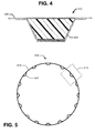
- FIGS 4 and 5 illustrate a randomly damaged area 510 of the fuselage 110.
- the underlying integrated stiffening substructure 420 may also be damaged.
- the stiffening substructure may include longitudinally-extending stringers 420, which are co-cured with the skin 410.
- FIG. 6 illustrates a replacement panel 610 that is attached to a skin panel 620 via a bolted splice.
- the bolted splice includes a doubler 630 that is attached to both the replacement panel 610 and the skin panel 620 by bolts 640.
- Non-structural filler 650 may be used to fill gaps between the doubler 630 and the replacement panel 610 or skin panel 620.
- the splices generally have circumferential, longitudinal, and corner configurations.
- Replacement panels may vary in size. Replacement panels may range from approximately 3' x 3' to upwards of approximately 42' x 20'.
- FIG. 7 illustrates a method of using the fabrication cell to create a custom one-piece replacement panel.
- a design of a customized composite replacement panel for replacing the damaged area of the composite component is received.
- the design includes a detail panel definition for skin and integrated stiffening substructure. This may include creating a detail panel definition based on skin and substructure that were originally used in the section, and modifying the original panel definition so the replacement panel can fit in the opening and match the contour of the component.
- Creating the panel definition includes creating an engineering geometry including ply boundaries, stacking sequence, fiber composition and orientations, and tape widths within each boundary.
- the detail panel definition specifies a one-piece replacement panel. That is, all underlying stiffening structure is co-cured with the skin. In other embodiments, the detail panel definition does not specify a one-piece replacement panel, but rather a hybrid that includes custom-made integrated skin and stiffening substructure along with other elements.
- the design also includes a detail panel definition for mechanical fastening elements (e.g., splice doublers and fillers), which will be used to mechanically fasten the replacement panel to the component. Since the exact location of the damaged material and the exact extent of the damage is random and unpredictable, the splice joint configuration and details for the repair are likely not to exist and need to be created. The number of detail panels depends on size and complexity of the repair. In a complex repair, for instance, dozens of splice doublers and thousands of fasteners might be involved. This phase of design is unique to the damage.
- mechanical fastening elements e.g., splice doublers and fillers
- the design may also include a panel assembly definition and an installation definition. These definitions describe how to attach the replacement panel to the component using the fastening elements (e.g., splice doublers, fillers, and fasteners).
- fastening elements e.g., splice doublers, fillers, and fasteners.
- the replacement panel is fabricated according to the design at a fabrication cell.
- the various elements e.g., skin and stiffeners
- some of the elements of the replacement panel may be mechanically fastened together (e.g., excised stringers bolted together and to the skin).
- co-curing is preferable, especially if the co-cured panel matches the existing configuration.
- Additional cutting may be performed after the replacement panel has been fabricated. For instance, additional cutting may be performed if the replacement panel is larger than the opening. Additional trimming may be performed to ensure that engineering gap tolerances are met. This final fit up, which ensures that engineering gap tolerances are met, may be done at the repair site. The replacement panels may intentionally have usable excess which is trimmed at the repair site.
- the replacement panel is shipped to the repair site, where it is installed into the opening.
- the installation may include mechanically fastening the replacement panel to the component.
- numerous splice doublers composite and/or titanium
- fillers and brackets may be used to fasten the replacement panel to the section.
- composite and metallic (e.g., titanium) fabrication techniques may be used to fabricate splice doublers and other elements for fastening the replacement panel.
- titanium fastening alone, or composite elements alone, or a combination of titanium and composite fastening elements may be used.
- the elements made of titanium may be fabricating by conventional titanium fabrication processes such as hot forming and machining.
- the composite fastening elements may be fabricated by conventional composite prepreg fabrication techniques such as hand layup, bag, cure, trim and non-destructive ultrasonic inspection. Automated Fiber Placement (AFP) may be used instead of hand layup where permitted by engineering.
- AFP Automated Fiber Placement
- composite doublers, fillers, and splices could be built using the same production site following the same or similar processes as the replacement panel.
- the fabrication cell and method of Figure 7 may be used to repair a new class of commercial aircraft having one or more one-piece composite components.
- a damaged one-piece section is repaired quickly (much faster than replacing an entire section), which allows the aircraft to be returned to service quickly. Consequently, aircraft down time is reduced.
- An advantage of the production cell is that it may be located remotely from the aircraft manufacturer's main production facility. For instance, a fabrication cell may be located closer to an airport or other location where aircraft will be repaired. The closer location saves significant logistics costs (e.g., packaging, transportation) and reduces flow time. This further reduces down time.
- logistics costs e.g., packaging, transportation
- Fabricating the mandrel tool and using it at the same site also saves significant logistics costs and reduces flow time.
- building the layup mandrel tool at one site and using it at another site may involve extra steps, such as shipping the mandrel tool to the build site, and unpacking the tool and setting up the tool at the build site.
Description
- Commercial aircraft may be damaged by bird strikes, ground handling equipment, debris, hail and other unplanned events. These events can create holes and tears in aircraft skin, and damage to underlying stiffening substructure (e.g., frames, stiffeners and pad-ups). For instance, an aircraft's nose cab section may be damaged by a bird strike, a lower lobe may be damaged due to nose gear collapse, mid-section door surrounds may be damaged due to collisions with ground handling equipment, an end section lower lobe may be damaged by a tail strike, etc.
- It is important to repair a damaged aircraft and return it to service as quickly as possible. Down time is very costly to an aircraft carrier, as an idle aircraft results in lost revenue.
- Repair of a panelized aluminum aircraft is relatively straightforward. A damaged panel and underlying substructure are removed from the aircraft and replaced. If panels are available, the repair can be implemented relatively quickly.
- Repair of composite commercial aircraft is not so straightforward, especially for large area repair of one a piece component. Consider a fuselage made up of several one-piece composite barrel sections. Each barrel section includes skin, hoop frames, and stiffeners (e.g., stringers). The stiffeners may be integrated with the skin (by co-curing during fabrication). The hoop frames may be mechanically fastened to the skin. If a large area of a fuselage section becomes damaged, removing and replacing the entire barrel section would be prohibitively expensive, disruptive to production, and time consuming.
- Document
GB 2 116 594 A - Document
US 5 341 918 A shows an article transfer device for transferring articles from a first position to a second position including a transfer screw, a conveying system, a stationary dead plate and a pressure adjustment wall. The screw is constructed from a flexible material and is essentially a continuous helical spiral having its ends connected to a support structure. Because of the flexible nature of the screw, different size articles can be transferred across the dead plate without having to change the screw. The article transfer device is useful in a clean room and less clean room application where articles need to be transferred between the rooms without returning any contaminants to the clean room. No individual part of the transfer device moves from the clean room to the less clean room and back again, thereby maintaining the sterile environment in the clean room. When it is desired that a different size article be transferred between the rooms, the pressure wall is adjusted so that the screw conforms to the different size articles and transfers the same. Lost production time and additional labor are eliminated as a result of the conforming nature of the article transfer device. - Document
US 2006/0180264 A1 shows a composite item fabricated with a device. The device includes an end effector and a positioning device. The end effector places a tow. The end effector includes a spindle, compaction device, and a path. The spindle detachably secures a spool of tow and the path is disposed from the spool to the compaction device. The positioning device positions the end effector. The end effector is detachably secured to the positioning device. - An infrastructure for large area repair of one-piece composite aircraft components is needed.
- According to an embodiment herein, a method is provided of using a fabrication all to a method of using a fabrication cell to fabricate a composite part, the fabrication cell comprising a clean section for performing clean operations including laying up the reinforcing fibers on a mandrel tool, the clean section satisfying clean room requirements for processing uncured composite materials; an adjacent dirty section for performing dirty operations including machining the layup after curing; a common end effector positioning system movable between the clean and dirty sections; and means for preventing contaminants in the dirty section from entering the clean section; the method comprising: using the end effector positioning system to build a mandrel tool in the dirty section; moving the mandrel tool and the end effector positioning system into the clean section; using the end effector positioning system to deposit reinforcing fibers on the tool; moving the tool to a curing section and performing curing; moving the mandrel tool and end the effector positioning system back into the dirty section; machining the cured part on the tool.
- According to another embodiment herein, a fabrication cell includes a clean section including interchangeable end effectors for performing composite layup operations. The clean section satisfies clean room requirements for processing uncured composite materials. The fabrication cell further includes a dirty section adjacent the clean section, the dirty section including interchangeable end effectors for performing machining operations; and an end effector positioning system, movable between the clean and dirty sections, for selecting and using the end effectors to perform the layup operations in the clean section and the machining operations in the dirty section.
-
-
Figure 1 is an illustration of a fabrication cell having adjacent clean and dirty sections. -
Figure 2 is an illustration of a method of using the fabrication cell to fabricate a layup mandrel tool and composite part. -
Figure 3 is an illustration of an aircraft including a composite fuselage. -
Figure 4 is an illustration of skin and underlying stiffening substructure of a composite barrel section of the fuselage. -
Figure 5 is an illustration of a damaged area of a one-piece fuselage barrel. -
Figure 6 is an illustration of a replacement panel that is attached to a skin panel via a bolted splice. -
Figure 7 is an illustration of a method for repairing a damaged one-piece composite component of an aircraft, including design and fabrication of a composite replacement panel. - Reference is made to
Figure 1 , which illustrates afabrication cell 110 for manufacturing a composite part including layers or plies of reinforcing fibers embedded in a matrix. One example of a composite is carbon fiber reinforced plastic (CFRP), where the constituents may include carbon fibers embedded in an epoxy matrix. - The
fabrication cell 110 includes adirty section 120 and aclean section 130. Operations in thedirty section 120 include, but are not limited to, assembly and machining (e.g., trimming, milling and drilling). Operations are considered dirty if they can produce dust or contaminants that violate clean room requirements for the processing of uncured composite materials. For "dirty" operations such as machining, thedirty section 120 may include avacuum system 122 for minimizing dust and debris to facilitate cleaning. Thevacuum system 122 may have up to 98% or greater effectiveness from removing dust. - Operations in the
clean section 130 include composite layup on a mandrel tool. In some embodiments, fibers may be deposited on a layup mandrel tool that is static. In other embodiments, fibers may be deposited on a layup mandrel tool while the tool is being rotated. - Operations in the
clean section 130 further include caul plate installation, bagging, and material cutting. For instance, fabric for resin infusion or pre-impregnation could be cut by an ultrasonic knife or other device, such as a ply cutter or a hand tool. Resin infusion may also be performed in theclean section 130. - Operations are considered clean if they do not violate clean room requirements and require being performed in a clean room due to contamination concerns (e.g., processes that involve handling uncured composite materials). The
clean section 130 may include an air filtration andconditioning system 132 for maintaining environmental conditions within specification. Generally, composite facilities require 400,000 class clean rooms with temperature, humidity, and particle count monitored. The equipment and tooling should satisfy these requirements when moved from thedirty section 120 to theclean section 130. Should theclean section 130 fall out specification, wait time may be required for air circulation filters of thesystem 132 to remove dust from the air. - The
fabrication cell 110 includes a common endeffector positioning system 140, movable between the dirty andclean sections effector positioning system 140 may use a plurality of interchangeable end effectors for performing the operations. The end effectors may be located atend effector stations 150 located in the dirty andclean sections clean sections - The end effectors may include tools for machining (e.g., milling, drilling), tools for trimming, a lamination head for tape or slit tape tow laydown of the panel or face sheet, a paint spray head for painting, an ultrasonic cutter for cutting prepreg or dry material, an NDI head (with necessary shoes) for ultrasonic inspection of the composite part, a stringer roll former for forming composite parts, a material dispenser, and inspection probes for geometric and dimensional inspection of the composite part.
- In some embodiments, the end
effector positioning system 140 may include a single positioning machine such as agantry 142 having multiple axes of motion (e.g., up to seven axes). In other embodiments, thepositioning system 140 may include a robot or multiple robots for performing the clean and dirty operations. A single robot may have interchangeable end effectors. Multiple robots may use combinations of dedicated end effectors. Other types of end effector positioning systems may include combinations of linear Cartesian axis platforms, rotary axis platforms, and Stewart platforms using parallel kinematics. Specific examples include gantries, robots, robots-on-rail, post-mill type platforms, and Stewart platforms (e.g. hexapods). In each of these examples, the endeffector positioning system 140 is configured to deliver a selected end effector to a position or along a path to perform its function, while satisfying performance requirements (e.g., angles, velocity, acceleration, stiffness, range of travel, utilities, quick-release coupling). - The end
effector positioning system 140 is movable between the dirty andclean sections effector positioning system 140 may be moved by amachine rail system 160. In other embodiments, the endeffector positioning system 140 may be moved via air bearings or wheels, and then locally positioned. - A
mandrel tool support 170 is provided to support the mandrel tool during layup. In some embodiments, the mandrel tool support may include a table 170 that is moveable between dirty andclean sections gantry 142. - The end
effector positioning system 140 may be covered with sheet metal or other material that provides a smooth surface for cleaning. The endeffector positioning system 140 may also utilize polyethylene type plastic as a protective covering. Such plastic may be easily removed for cleaning before transferring thegantry 142 from thedirty section 120 to theclean section 130. This all helps to maintain clean room requirements. - In some embodiments, a
barrier 180 such as a fast door, strip door or freezer door separates the dirty andclean sections clean section 130 may be positive pressurized to keep out dust and other contaminants. - In some embodiments, the
barrier 180 may include an airlock, which may be fixed or portable. The airlock may include of a chamber with two airtight doors in series which do not open simultaneously. In general, an airlock permits the passage of people and objects between a pressure vessel and its surroundings while minimizing the change of pressure in the vessel and loss of air from it. An airlock having an accordion design may include a portable sealed chamber that covers the endeffector positioning system 140 as it transitions between thesections clean section 130. - For movement from the
clean section 130 to the dirty section120, the clean section door is opened, the end-effector positioning system 140 (which is already clean) is moved into the airlock, the clean section door is shut, the dirty section door is opened, and the endeffector positioning system 140 is moved into thedirty section 120. The dirty section door is then shut. For movement from thedirty section 120 to theclean section 130, the dirty section door is opened, the end-effector positioning system 140 (which is already dirty) is moved into the airlock, and the dirty section door is closed (the clean section door is already closed). The endeffector positioning system 140 is cleaned (e.g., protective coverings are stripped off, and the system is wiped down). After the environment inside the airlock is validated as clean, the clean section door is opened, and the endeffector positioning system 140 is moved into theclean section 130. - The
fabrication cell 110 may also include anearby curing section 190 for curing of the composite part. In some embodiments, thecuring section 190 may include anautoclave 192 for curing prepregs under heat and pressure. In other embodiments, thecuring section 190 may include anoven 194 for curing resin-infused fabric under heat or prepreg material designed for out-of autoclave processing. - The
curing section 190 is preferably adjacent to theclean section 130. Close proximity simplifies handling logistics. The composite part may be shuttled to the autoclave on heat suitable castors or wheels on the underside of the mandrel tool or on a dolly designed to withstand autoclave cure. - Nondestructive inspection of the cured composite part may be performed in the
dirty section 120, provided that dust does not interfere with the non destructive inspection operation. Nondestructive inspection may be performed in theclean section 130, provided that the coupling (e.g. water) is controlled so as not to violate clean room requirements. - The end
effector positioning system 140 may also include acommon controller 144 for moving the end effector positioning system 140 (e.g., gantry 142) along therail system 160 and commanding the endeffector positioning system 140 to perform the clean and dirty operations. Thecontroller 144 may be fed programs from a programming and simulation tool. This programming and simulation tool may be designed to provide the necessary instructions for all end-effector types used within thefabrication cell 110. - The
fabrication cell 110 may be used to fabricate more than the composite part. It may also be used to fabricate the mandrel tool upon which the composite part is formed. Thefabrication cell 610 may be equipped with end effectors for fabricating layup mandrel tools. As a first example, thefabrication cell 610 may be equipped with end effectors for producing a master tool (e.g. composite), which in turn can be used to cast composite production tools. As a second example, thefabrication cell 610 may be equipped with end effectors having milling and drilling capabilities for producing a metal layup tool. - Reference is now made to
Figure 2 , which illustrates a method of using thefabrication cell 110 to fabricate both a layup mandrel tool and a composite part. InFigure 2 , a particular type of layup tool is fabricated: a masterless tool including a cellular structure filled with foam and covered with a composite face sheet, which provides an aero-smooth layup surface. InFigure 7 , the composite part is not limited to any particular type or application. It may be a production part, a replacement panel, a fastening element (e.g., a doubler), etc. The composite part may be for a vehicle (e.g., aircraft, space, boat, car, truck), a wind generator (e.g., a blade), or a civil engineering structure (e.g., a bridge element for reinforcement). - At
block 200, thecontroller 144 receives instructions for fabricating the tool and part. The instructions provide the commands for the endeffector positioning system 140 to select end effectors and use the selected end effectors to perform their desired functions. For a hole drilling end-effector, the instructions may include position and angle of the drill, feed rate, rotation speed, and drill cycle instructions. For milling of a tool or edge trimming of a part, the milling end-effector instructions may include the path for the cutter, angular position, rotation speed, and feed rate. For a fiber placement end effector, the instructions may include the path for the head, angular position, and cut and add commands for the different tows. The instructions may be produced by a programming and simulation module , which is designed for thefabrication cell 110. The programming and simulation module derives the instructions from engineering models associated with the composite part and tool. The models identify surface geometry and features such as holes, trim locations, and ply boundaries. The engineering models define the part and tool requirements. The programming and simulation module takes these requirements from the engineering models and converts them into instructions that can be processed by thefabrication cell 110. Thecontroller 144 then executes the instructions to perform the following. - At
block 210, a cellular structure of the layup mandrel tool is built in thedirty section 120. The layup mandrel tool may be built with composite header boards, which may be cut with a water jet cutting tool or a router tool. In some embodiments, the header boards may be assembled on and secured to a moveable table, whereby the moveable table "becomes" part of the mandrel tool. - The resulting cellular structure is assembled and filled with foam, using dispensed and mixed liquid, blocks of pre-cast material, or a combination thereof. For instance, the end
effector positioning system 140 selects a foam material dispenser or a handling end effector from theend effector station 150. The dispenser is selected for tooling foam application such as a 2-part polyisocyanurate system. The handling end effector is selected to place pre-cured foam tooling blocks in the tool header boards. - Following build up, the end
effector positioning system 140 selects a milling end effector from theend effector station 150, loads the milling end effector, and machines the foam and header board. The endeffector positioning system 140 then selects and loads a probe head, and uses the probe head for location verification or inspection to validate geometry. - At
block 220, reinforcing fibers for a face sheet is laid up on the machined cellular structure in theclean section 130. In some embodiments, fabric may be dispensed by a fabric dispensing end effector, and the dispensed fabric may be cut by an ultrasonic cutting knife end effector. The fabric may be deposited by an end effector that performs automated fiber placement (AFP) or automated tape layer (ATL). In other embodiments, the layup may be performed manually. - At
block 230, the composite material is cured in thecuring section 190. A resin-infused layup is cured in the oven, or a prepreg layup is cured in the autoclave, or an out-of-autoclave system is cured in an oven. Resin infusion may include a post-cure at approximately 350°F for epoxy materials, and higher for BMI materials. Prior to post-curing, the foam-like material may be removed from the mandrel tool, especially for tools having taller header boards. - At
block 240, the face sheet is machined in thedirty section 120. Any necessary hand finish is also performed in the dirty section. Appropriate vacuum is utilized for dust collection. Sealing of the tool may also be performed using an automated end effector (spray of roller) or manual process. A finished layup mandrel tool is then cleaned and transferred to the clean section for panel layup. - At
block 250, composite material for the composite part is laid up on the mandrel tool in the clean section. The part layup may be performed automatically by the end effector positioning system 140 (for example, with an end effector that performs AFP or ATL) or the panel layup may be performed manually. - Caul plates may then be placed on the part layup (depending on finish requirements). The part layup is then bagged, and moved to the curing section.
- At
block 260, the composite part is cured in thecuring section 190. Atblock 270, the cured part is transferred to the dirty section120, where trimming and drilling are performed. - At
block 280, following trimming and drilling, the finished part is removed from the layup tool. A relatively large part may be removed with a lifting fixture. The finished part is placed on an NDI fixture to enable ultrasonic inspection. The endeffector positioning system 140 may perform NDI by selecting NDI end effectors (shoes) that are applicable for the part geometry. - At
block 290, following NDI, the part is moved to the dirty section, where it is painted (in other embodiments, the painting may be performed in a separate facility). The gantry may use a painting end effector. Some additional ventilation (portable ducts, etc.) may be provided to facilitate painting in the dirty section. - The layup mandrel tool and the end
effector positioning system 140 are cleaned prior to moving from thedirty section 120 to theclean section 130. If foam or carbon fiber are cut, a high performancevacuum collection system 122 may be deployed to minimize dust, possibly with some coolant to keep airborne particles to a minimum. - A
fabrication cell 110 herein offers advantages over conventional fabrication facilities. End effector positioning systems tend to be very expensive, so capital expenditure on equipment is reduced significantly by using a common end effector positioning system instead of dedicated systems for different functions. - A fabrication cell herein can fabricate parts faster than facilities that perform clean and dirty operations in a single section. The only element that needs to be cleaned between clean and dirty operations is the end
effector positioning system 140. Time is not spent waiting for particle counts to settle before clean operations are performed. - A fabrication cell herein has a relatively small footprint. Consider an example of a fabrication cell for fabricating parts as large as 45 feet long, 20 feet wide, and 12 feet tall. Such a cell may have a floor area of about 5,000 square feet and a ceiling height of about 25 feet. The floor of the fabrication cell may be Hat, with a foundation sufficient for the weight and loading of the end
effector positioning system 140. The relatively small footprint enables multiple fabrication cells to be constructed at different locations instead of a single large cell being constructed at a large central facility. - These advantages will be especially useful for repairing of a new class of commercial aircraft. This new class of aircraft includes large one-piece sections made of composite material.
- Reference is made to
Figure 3 , which illustrates an example of acomposite aircraft 300. Theaircraft 300 generally includes afuselage 310,wing assemblies 320, andempennage 330. One ormore propulsion units 340 are coupled to thefuselage 310,wing assemblies 320 or other portions of theaircraft 300.Landing gear assemblies 350 are coupled to thefuselage 310. - In some embodiments, the
entire fuselage 310 may be made of a single one-piece composite section. In other embodiments, thefuselage 310 may be formed by multiple one-piece composite sections. In the example illustrated inFigure 3 , thefuselage 310 is formed from the following one-piece composite barrel sections: a nose cab section (section 41), three mid sections (sections section 47 and 48). - Passenger and
cargo doors 360 are formed in five sections. Thus, all sections are susceptible to damage from ground handling equipment. All sections are also susceptible to damage from ground debris. The nose cab section is also susceptible to damage from bird strikes, which are high energy impacts. A lower lobe of the nose cab section is susceptible to damage due to nose gear collapse. A lower lobe of the end section is susceptible to damage by tail strikes. - In a large commercial aircraft, it is far more desirable to replace the damaged area than replace an entire one-piece barrel. Still, the damaged area will usually be random. That is, the location, exact size, and extent of the damage may vary from incident to incident. Consequently, a pre-fabricated panel might not fit well, or at all, into a damaged area. Advantageously, a fabrication cell herein may be used to fabricate tool and panels that are customized to replace the damaged areas.
- A fabrication cell herein may also be used to produce composite production parts and tools for the parts. Examples of production parts include, but are not limited to, nacelles, wing ribs, center box structures, and door structures.
- Reference is now made to
Figures 4 and 5 , which illustrate a randomly damagedarea 510 of thefuselage 110. In addition to damage to theskin 410, the underlyingintegrated stiffening substructure 420 may also be damaged. The stiffening substructure may include longitudinally-extendingstringers 420, which are co-cured with theskin 410. - Reference is made to
Figure 6 , which illustrates areplacement panel 610 that is attached to askin panel 620 via a bolted splice. The bolted splice includes adoubler 630 that is attached to both thereplacement panel 610 and theskin panel 620 bybolts 640.Non-structural filler 650 may be used to fill gaps between thedoubler 630 and thereplacement panel 610 orskin panel 620. The splices generally have circumferential, longitudinal, and corner configurations. - Replacement panels may vary in size. Replacement panels may range from approximately 3' x 3' to upwards of approximately 42' x 20'.
- Reference is now made to
Figure 7 , which illustrates a method of using the fabrication cell to create a custom one-piece replacement panel. Atblock 710, a design of a customized composite replacement panel for replacing the damaged area of the composite component is received. The design includes a detail panel definition for skin and integrated stiffening substructure. This may include creating a detail panel definition based on skin and substructure that were originally used in the section, and modifying the original panel definition so the replacement panel can fit in the opening and match the contour of the component. Creating the panel definition includes creating an engineering geometry including ply boundaries, stacking sequence, fiber composition and orientations, and tape widths within each boundary. - In some embodiments, the detail panel definition specifies a one-piece replacement panel. That is, all underlying stiffening structure is co-cured with the skin. In other embodiments, the detail panel definition does not specify a one-piece replacement panel, but rather a hybrid that includes custom-made integrated skin and stiffening substructure along with other elements.
- The design also includes a detail panel definition for mechanical fastening elements (e.g., splice doublers and fillers), which will be used to mechanically fasten the replacement panel to the component. Since the exact location of the damaged material and the exact extent of the damage is random and unpredictable, the splice joint configuration and details for the repair are likely not to exist and need to be created. The number of detail panels depends on size and complexity of the repair. In a complex repair, for instance, dozens of splice doublers and thousands of fasteners might be involved. This phase of design is unique to the damage.
- The design may also include a panel assembly definition and an installation definition. These definitions describe how to attach the replacement panel to the component using the fastening elements (e.g., splice doublers, fillers, and fasteners).
- At
block 720, the replacement panel is fabricated according to the design at a fabrication cell. In some embodiments, the various elements (e.g., skin and stiffeners) are co-cured as is done in production. In other embodiments, some of the elements of the replacement panel may be mechanically fastened together (e.g., excised stringers bolted together and to the skin). However, co-curing is preferable, especially if the co-cured panel matches the existing configuration. - Additional cutting may be performed after the replacement panel has been fabricated. For instance, additional cutting may be performed if the replacement panel is larger than the opening. Additional trimming may be performed to ensure that engineering gap tolerances are met. This final fit up, which ensures that engineering gap tolerances are met, may be done at the repair site. The replacement panels may intentionally have usable excess which is trimmed at the repair site.
- At
block 730, the replacement panel is shipped to the repair site, where it is installed into the opening. The installation may include mechanically fastening the replacement panel to the component. For instance, numerous splice doublers (composite and/or titanium), fillers, and brackets may be used to fasten the replacement panel to the section. - Conventional composite and metallic (e.g., titanium) fabrication techniques may be used to fabricate splice doublers and other elements for fastening the replacement panel. In some embodiments, titanium fastening alone, or composite elements alone, or a combination of titanium and composite fastening elements may be used. The elements made of titanium may be fabricating by conventional titanium fabrication processes such as hot forming and machining. The composite fastening elements may be fabricated by conventional composite prepreg fabrication techniques such as hand layup, bag, cure, trim and non-destructive ultrasonic inspection. Automated Fiber Placement (AFP) may be used instead of hand layup where permitted by engineering. In some embodiments, composite doublers, fillers, and splices could be built using the same production site following the same or similar processes as the replacement panel.
- Thus, the fabrication cell and method of
Figure 7 may be used to repair a new class of commercial aircraft having one or more one-piece composite components. A damaged one-piece section is repaired quickly (much faster than replacing an entire section), which allows the aircraft to be returned to service quickly. Consequently, aircraft down time is reduced. - An advantage of the production cell is that it may be located remotely from the aircraft manufacturer's main production facility. For instance, a fabrication cell may be located closer to an airport or other location where aircraft will be repaired. The closer location saves significant logistics costs (e.g., packaging, transportation) and reduces flow time. This further reduces down time.
- Fabricating the mandrel tool and using it at the same site also saves significant logistics costs and reduces flow time. In contrast, building the layup mandrel tool at one site and using it at another site may involve extra steps, such as shipping the mandrel tool to the build site, and unpacking the tool and setting up the tool at the build site.
Claims (7)
- A method of using a fabrication cell (110) to fabricate a composite part, the fabrication cell comprising a clean section (130) for performing clean operations including laying up the reinforcing fibers on a mandrel tool, the clean section satisfying clean room requirements for processing uncured composite materials; an adjacent dirty section (120) for performing dirty operations including machining the layup after curing; a common end effector positioning system (140) movable between the clean and dirty sections; and means (180) for preventing contaminants in the dirty section (120) from entering the clean section (130); the method comprising:using the end effector positioning system (110) to build a mandrel tool in the dirty section (120);moving the mandrel tool and the end effector positioning system (140) into the clean section (130);using the end effector positioning system (140) to deposit reinforcing fibers on the tool;moving the tool to a curing section (190) and performing curing;moving the mandrel tool and end the effector positioning system back into the dirty section;machining the cured part on the tool.
- The method of claim 1, further comprising cleaning the end effector positioning system before it is moved into the clean section.
- A fabrication cell (110) comprising:a clean section (130) including interchangeable end effectors for performing composite layup operations, the clean section (150) satisfying clean room requirements for processing uncured composite materials;a dirty section (120) adjacent the clean section (130), the dirty section (120) including interchangeable end effectors for performing machining operations; andan end effector positioning system (140), movable between the clean and dirty sections, for selecting and using the end effectors to perform the layup operations in the clean section (130) and the machining operations in the dirty section (120).
- The fabrication cell of claim 3, further comprising means (180) preventing contaminants in the dirty section from entering the clean section.
- The fabrication cell of either claim 3 or 4, further comprising means (160) for moving the end effector positioning system between the clean and dirty sections.
- The fabrication cell of any of claims 3-5, further comprising means for maintaining temperature, humidity, and particle count in the clean section to satisfy the composite material process requirements.
- The fabrication cell of any of claims 3-6, further comprising a common controller (144) for controlling the end effector positioning system (140) and selected end effectors in both the clean and dirty sections.
Applications Claiming Priority (3)
| Application Number | Priority Date | Filing Date | Title |
|---|---|---|---|
| US201161507115P | 2011-07-12 | 2011-07-12 | |
| US13/267,876 US8887367B2 (en) | 2011-07-12 | 2011-10-06 | Cell including clean and dirty sections for fabricating composite parts |
| PCT/US2012/046303 WO2013009909A2 (en) | 2011-07-12 | 2012-07-11 | Cell including clean and dirty sections for fabricating composite parts |
Publications (2)
| Publication Number | Publication Date |
|---|---|
| EP2731784A2 EP2731784A2 (en) | 2014-05-21 |
| EP2731784B1 true EP2731784B1 (en) | 2015-06-10 |
Family
ID=46598955
Family Applications (1)
| Application Number | Title | Priority Date | Filing Date |
|---|---|---|---|
| EP12741164.3A Active EP2731784B1 (en) | 2011-07-12 | 2012-07-11 | Cell including clean and dirty sections for fabricating composite parts |
Country Status (9)
| Country | Link |
|---|---|
| US (1) | US8887367B2 (en) |
| EP (1) | EP2731784B1 (en) |
| JP (1) | JP6025840B2 (en) |
| KR (1) | KR101874664B1 (en) |
| CN (1) | CN103826835B (en) |
| BR (1) | BR112014000556B1 (en) |
| CA (1) | CA2834546C (en) |
| ES (1) | ES2545635T3 (en) |
| WO (1) | WO2013009909A2 (en) |
Families Citing this family (11)
| Publication number | Priority date | Publication date | Assignee | Title |
|---|---|---|---|---|
| US9586699B1 (en) | 1999-08-16 | 2017-03-07 | Smart Drilling And Completion, Inc. | Methods and apparatus for monitoring and fixing holes in composite aircraft |
| US9625361B1 (en) | 2001-08-19 | 2017-04-18 | Smart Drilling And Completion, Inc. | Methods and apparatus to prevent failures of fiber-reinforced composite materials under compressive stresses caused by fluids and gases invading microfractures in the materials |
| US8728262B2 (en) * | 2011-07-12 | 2014-05-20 | The Boeing Company | Rapid fabrication of a composite part |
| US9381659B2 (en) * | 2014-04-16 | 2016-07-05 | The Boeing Company | Automated apparatus for use in selectively cutting side walls of a honeycomb core |
| US9545759B2 (en) | 2015-01-30 | 2017-01-17 | CGTech | Automated fiber placement with course trajectory compensation |
| US10265890B2 (en) | 2015-04-10 | 2019-04-23 | Channell Commercial Corporation | Method of manufacturing a thermoset polymer utility vault lid |
| US9987659B2 (en) | 2015-10-19 | 2018-06-05 | United Technologies Corporation | Nanotube enhancement of interlaminar performance for a composite component |
| JP6776200B2 (en) * | 2017-07-20 | 2020-10-28 | 三菱重工業株式会社 | Fastener and repair structure and damage detection method |
| EP4001129A1 (en) | 2020-11-18 | 2022-05-25 | The Boeing Company | Edge trimming for moving-line fabrication of aircraft |
| NL2027426B1 (en) * | 2021-01-26 | 2022-08-26 | Boeing Co | Edge trimming for moving-line fabrication of aircraft |
| CN117429090B (en) * | 2023-12-04 | 2024-04-30 | 哈尔滨远驰航空装备有限公司 | Airborne multi-cavity structure and integrated forming die and method thereof |
Family Cites Families (21)
| Publication number | Priority date | Publication date | Assignee | Title |
|---|---|---|---|---|
| GB211659A (en) * | 1923-01-11 | 1924-02-28 | Quicksafe Mfg Co | Improvements in or relating to can openers |
| US4292874A (en) | 1979-05-18 | 1981-10-06 | Baldwin Piano & Organ Company | Automatic control apparatus for chords and sequences |
| GB2116594B (en) | 1982-02-09 | 1985-05-30 | Glyndon Products Limited | Machine installations |
| JPH06127497A (en) * | 1992-10-20 | 1994-05-10 | Mitsubishi Heavy Ind Ltd | Rocket launching device |
| US5341918A (en) | 1993-04-16 | 1994-08-30 | Covert William J | Article transfer device |
| JPH11235782A (en) * | 1998-02-23 | 1999-08-31 | Matsushita Electric Works Ltd | Manufacture of metal foil-clad laminate |
| JP2000024971A (en) * | 1998-07-08 | 2000-01-25 | Komatsu Ltd | Teaching system of work carrying robot |
| US6506009B1 (en) * | 2000-03-16 | 2003-01-14 | Applied Materials, Inc. | Apparatus for storing and moving a cassette |
| JP3608107B2 (en) * | 2000-10-19 | 2005-01-05 | 日精樹脂工業株式会社 | Injection molding machine equipped with dust scattering prevention means |
| JP2003017376A (en) * | 2001-07-02 | 2003-01-17 | Sanki Eng Co Ltd | System and method for producing semiconductor |
| US6881374B2 (en) * | 2001-09-25 | 2005-04-19 | The United States Of America As Represented By The Secretary Of The Army | Method for induction lamination of electrically conductive fiber reinforced composite materials |
| JP2004207279A (en) * | 2002-12-20 | 2004-07-22 | Rorze Corp | Sheet-shaped object manufacturing facility |
| US7103952B2 (en) * | 2004-03-12 | 2006-09-12 | The Boeing Company | Engine loader and transporter apparatus and methods |
| US7341086B2 (en) | 2004-10-29 | 2008-03-11 | The Boeing Company | Automated fabric layup system and method |
| US7472736B2 (en) | 2005-02-14 | 2009-01-06 | The Boeing Company | Modular head lamination device and method |
| DE102005053690A1 (en) * | 2005-11-10 | 2007-05-31 | Airbus Deutschland Gmbh | Tool, assembly and method for manufacturing a component, component |
| US8691037B2 (en) * | 2006-12-14 | 2014-04-08 | The Boeing Company | Method for minimizing fiber distortion during fabrication of one-piece composite barrel section |
| ITTO20070507A1 (en) | 2007-07-11 | 2009-01-12 | Alenia Aeronautica Spa | PROCESS OF MANUFACTURING OF A STRUCTURE OF A MONOLITHIC WING WITH AN INTEGRAL PROFILE |
| US8557074B2 (en) * | 2008-02-27 | 2013-10-15 | The Boeing Company | Reduced complexity automatic fiber placement apparatus and method |
| DE102008044069B3 (en) * | 2008-11-26 | 2010-08-05 | Airbus Deutschland Gmbh | Shaped body for producing a fiber composite component |
| US8844108B2 (en) * | 2011-07-12 | 2014-09-30 | The Boeing Company | Large area repair of composite aircraft |
-
2011
- 2011-10-06 US US13/267,876 patent/US8887367B2/en active Active
-
2012
- 2012-07-11 BR BR112014000556-7A patent/BR112014000556B1/en active IP Right Grant
- 2012-07-11 JP JP2014520286A patent/JP6025840B2/en active Active
- 2012-07-11 EP EP12741164.3A patent/EP2731784B1/en active Active
- 2012-07-11 CA CA2834546A patent/CA2834546C/en active Active
- 2012-07-11 WO PCT/US2012/046303 patent/WO2013009909A2/en active Application Filing
- 2012-07-11 ES ES12741164.3T patent/ES2545635T3/en active Active
- 2012-07-11 CN CN201280033057.0A patent/CN103826835B/en active Active
- 2012-07-11 KR KR1020137029352A patent/KR101874664B1/en active IP Right Grant
Also Published As
| Publication number | Publication date |
|---|---|
| US20130014378A1 (en) | 2013-01-17 |
| WO2013009909A2 (en) | 2013-01-17 |
| JP2014525852A (en) | 2014-10-02 |
| CA2834546A1 (en) | 2013-01-17 |
| BR112014000556B1 (en) | 2022-01-04 |
| EP2731784A2 (en) | 2014-05-21 |
| CA2834546C (en) | 2016-06-14 |
| KR101874664B1 (en) | 2018-07-04 |
| WO2013009909A3 (en) | 2014-02-27 |
| CN103826835B (en) | 2016-02-03 |
| BR112014000556A2 (en) | 2020-10-27 |
| US8887367B2 (en) | 2014-11-18 |
| KR20140038400A (en) | 2014-03-28 |
| CN103826835A (en) | 2014-05-28 |
| JP6025840B2 (en) | 2016-11-16 |
| ES2545635T3 (en) | 2015-09-14 |
Similar Documents
| Publication | Publication Date | Title |
|---|---|---|
| EP2731784B1 (en) | Cell including clean and dirty sections for fabricating composite parts | |
| CA2778743C (en) | Large area repair of composite aircraft | |
| EP2731752B1 (en) | Rapid fabrication of a composite part | |
| EP4000841A1 (en) | Composite assembly for unhardened fuselage components | |
| EP4000845A1 (en) | Fabrication systems and methods for fuselage sections | |
| EP4000846A1 (en) | Fabrication line and systems for fuselage sections | |
| EP4000847A1 (en) | Fabrication system for fuselage sections | |
| NL2027417B1 (en) | Fabrication line, systems, and methods for fuselage sections | |
| NL2027419B1 (en) | Fabrication line, systems, and methods for fuselage sections | |
| NL2027415B1 (en) | Fabrication line, systems, and methods for fuselage sections | |
| EP4000910B1 (en) | Fabrication line, systems, and methods for fuselage sections | |
| US20230219307A1 (en) | Composite Fuselage Fabrication |
Legal Events
| Date | Code | Title | Description |
|---|---|---|---|
| PUAI | Public reference made under article 153(3) epc to a published international application that has entered the european phase |
Free format text: ORIGINAL CODE: 0009012 |
|
| 17P | Request for examination filed |
Effective date: 20140205 |
|
| AK | Designated contracting states |
Kind code of ref document: A2 Designated state(s): AL AT BE BG CH CY CZ DE DK EE ES FI FR GB GR HR HU IE IS IT LI LT LU LV MC MK MT NL NO PL PT RO RS SE SI SK SM TR |
|
| RIC1 | Information provided on ipc code assigned before grant |
Ipc: B29C 70/32 20060101ALI20141105BHEP Ipc: B29C 35/02 20060101ALI20141105BHEP Ipc: B29C 70/00 20060101AFI20141105BHEP Ipc: B29C 70/30 20060101ALI20141105BHEP Ipc: B29C 73/04 20060101ALI20141105BHEP |
|
| GRAP | Despatch of communication of intention to grant a patent |
Free format text: ORIGINAL CODE: EPIDOSNIGR1 |
|
| DAX | Request for extension of the european patent (deleted) | ||
| INTG | Intention to grant announced |
Effective date: 20150108 |
|
| GRAS | Grant fee paid |
Free format text: ORIGINAL CODE: EPIDOSNIGR3 |
|
| GRAA | (expected) grant |
Free format text: ORIGINAL CODE: 0009210 |
|
| AK | Designated contracting states |
Kind code of ref document: B1 Designated state(s): AL AT BE BG CH CY CZ DE DK EE ES FI FR GB GR HR HU IE IS IT LI LT LU LV MC MK MT NL NO PL PT RO RS SE SI SK SM TR |
|
| REG | Reference to a national code |
Ref country code: GB Ref legal event code: FG4D |
|
| REG | Reference to a national code |
Ref country code: CH Ref legal event code: EP |
|
| REG | Reference to a national code |
Ref country code: AT Ref legal event code: REF Ref document number: 730713 Country of ref document: AT Kind code of ref document: T Effective date: 20150715 |
|
| REG | Reference to a national code |
Ref country code: DE Ref legal event code: R096 Ref document number: 602012007934 Country of ref document: DE |
|
| REG | Reference to a national code |
Ref country code: IE Ref legal event code: FG4D |
|
| REG | Reference to a national code |
Ref country code: ES Ref legal event code: FG2A Ref document number: 2545635 Country of ref document: ES Kind code of ref document: T3 Effective date: 20150914 |
|
| PG25 | Lapsed in a contracting state [announced via postgrant information from national office to epo] |
Ref country code: FI Free format text: LAPSE BECAUSE OF FAILURE TO SUBMIT A TRANSLATION OF THE DESCRIPTION OR TO PAY THE FEE WITHIN THE PRESCRIBED TIME-LIMIT Effective date: 20150610 Ref country code: NO Free format text: LAPSE BECAUSE OF FAILURE TO SUBMIT A TRANSLATION OF THE DESCRIPTION OR TO PAY THE FEE WITHIN THE PRESCRIBED TIME-LIMIT Effective date: 20150910 Ref country code: LT Free format text: LAPSE BECAUSE OF FAILURE TO SUBMIT A TRANSLATION OF THE DESCRIPTION OR TO PAY THE FEE WITHIN THE PRESCRIBED TIME-LIMIT Effective date: 20150610 |
|
| REG | Reference to a national code |
Ref country code: AT Ref legal event code: MK05 Ref document number: 730713 Country of ref document: AT Kind code of ref document: T Effective date: 20150610 |
|
| REG | Reference to a national code |
Ref country code: NL Ref legal event code: MP Effective date: 20150610 |
|
| PG25 | Lapsed in a contracting state [announced via postgrant information from national office to epo] |
Ref country code: BG Free format text: LAPSE BECAUSE OF FAILURE TO SUBMIT A TRANSLATION OF THE DESCRIPTION OR TO PAY THE FEE WITHIN THE PRESCRIBED TIME-LIMIT Effective date: 20150910 Ref country code: RS Free format text: LAPSE BECAUSE OF FAILURE TO SUBMIT A TRANSLATION OF THE DESCRIPTION OR TO PAY THE FEE WITHIN THE PRESCRIBED TIME-LIMIT Effective date: 20150610 Ref country code: LV Free format text: LAPSE BECAUSE OF FAILURE TO SUBMIT A TRANSLATION OF THE DESCRIPTION OR TO PAY THE FEE WITHIN THE PRESCRIBED TIME-LIMIT Effective date: 20150610 Ref country code: GR Free format text: LAPSE BECAUSE OF FAILURE TO SUBMIT A TRANSLATION OF THE DESCRIPTION OR TO PAY THE FEE WITHIN THE PRESCRIBED TIME-LIMIT Effective date: 20150911 |
|
| PG25 | Lapsed in a contracting state [announced via postgrant information from national office to epo] |
Ref country code: EE Free format text: LAPSE BECAUSE OF FAILURE TO SUBMIT A TRANSLATION OF THE DESCRIPTION OR TO PAY THE FEE WITHIN THE PRESCRIBED TIME-LIMIT Effective date: 20150610 |
|
| PG25 | Lapsed in a contracting state [announced via postgrant information from national office to epo] |
Ref country code: RO Free format text: LAPSE BECAUSE OF NON-PAYMENT OF DUE FEES Effective date: 20150610 Ref country code: PT Free format text: LAPSE BECAUSE OF FAILURE TO SUBMIT A TRANSLATION OF THE DESCRIPTION OR TO PAY THE FEE WITHIN THE PRESCRIBED TIME-LIMIT Effective date: 20151012 Ref country code: PL Free format text: LAPSE BECAUSE OF FAILURE TO SUBMIT A TRANSLATION OF THE DESCRIPTION OR TO PAY THE FEE WITHIN THE PRESCRIBED TIME-LIMIT Effective date: 20150610 Ref country code: AT Free format text: LAPSE BECAUSE OF FAILURE TO SUBMIT A TRANSLATION OF THE DESCRIPTION OR TO PAY THE FEE WITHIN THE PRESCRIBED TIME-LIMIT Effective date: 20150610 Ref country code: CZ Free format text: LAPSE BECAUSE OF FAILURE TO SUBMIT A TRANSLATION OF THE DESCRIPTION OR TO PAY THE FEE WITHIN THE PRESCRIBED TIME-LIMIT Effective date: 20150610 Ref country code: IS Free format text: LAPSE BECAUSE OF FAILURE TO SUBMIT A TRANSLATION OF THE DESCRIPTION OR TO PAY THE FEE WITHIN THE PRESCRIBED TIME-LIMIT Effective date: 20151010 Ref country code: SK Free format text: LAPSE BECAUSE OF FAILURE TO SUBMIT A TRANSLATION OF THE DESCRIPTION OR TO PAY THE FEE WITHIN THE PRESCRIBED TIME-LIMIT Effective date: 20150610 |
|
| REG | Reference to a national code |
Ref country code: CH Ref legal event code: PL |
|
| REG | Reference to a national code |
Ref country code: DE Ref legal event code: R097 Ref document number: 602012007934 Country of ref document: DE |
|
| PG25 | Lapsed in a contracting state [announced via postgrant information from national office to epo] |
Ref country code: MC Free format text: LAPSE BECAUSE OF FAILURE TO SUBMIT A TRANSLATION OF THE DESCRIPTION OR TO PAY THE FEE WITHIN THE PRESCRIBED TIME-LIMIT Effective date: 20150610 |
|
| PLBE | No opposition filed within time limit |
Free format text: ORIGINAL CODE: 0009261 |
|
| STAA | Information on the status of an ep patent application or granted ep patent |
Free format text: STATUS: NO OPPOSITION FILED WITHIN TIME LIMIT |
|
| REG | Reference to a national code |
Ref country code: IE Ref legal event code: MM4A |
|
| PG25 | Lapsed in a contracting state [announced via postgrant information from national office to epo] |
Ref country code: DK Free format text: LAPSE BECAUSE OF FAILURE TO SUBMIT A TRANSLATION OF THE DESCRIPTION OR TO PAY THE FEE WITHIN THE PRESCRIBED TIME-LIMIT Effective date: 20150610 Ref country code: CH Free format text: LAPSE BECAUSE OF NON-PAYMENT OF DUE FEES Effective date: 20150731 Ref country code: LI Free format text: LAPSE BECAUSE OF NON-PAYMENT OF DUE FEES Effective date: 20150731 |
|
| 26N | No opposition filed |
Effective date: 20160311 |
|
| PG25 | Lapsed in a contracting state [announced via postgrant information from national office to epo] |
Ref country code: SI Free format text: LAPSE BECAUSE OF FAILURE TO SUBMIT A TRANSLATION OF THE DESCRIPTION OR TO PAY THE FEE WITHIN THE PRESCRIBED TIME-LIMIT Effective date: 20150610 |
|
| REG | Reference to a national code |
Ref country code: FR Ref legal event code: PLFP Year of fee payment: 5 |
|
| PG25 | Lapsed in a contracting state [announced via postgrant information from national office to epo] |
Ref country code: IE Free format text: LAPSE BECAUSE OF NON-PAYMENT OF DUE FEES Effective date: 20150711 |
|
| PG25 | Lapsed in a contracting state [announced via postgrant information from national office to epo] |
Ref country code: BE Free format text: LAPSE BECAUSE OF FAILURE TO SUBMIT A TRANSLATION OF THE DESCRIPTION OR TO PAY THE FEE WITHIN THE PRESCRIBED TIME-LIMIT Effective date: 20150610 |
|
| PG25 | Lapsed in a contracting state [announced via postgrant information from national office to epo] |
Ref country code: MT Free format text: LAPSE BECAUSE OF FAILURE TO SUBMIT A TRANSLATION OF THE DESCRIPTION OR TO PAY THE FEE WITHIN THE PRESCRIBED TIME-LIMIT Effective date: 20150610 |
|
| PG25 | Lapsed in a contracting state [announced via postgrant information from national office to epo] |
Ref country code: HU Free format text: LAPSE BECAUSE OF FAILURE TO SUBMIT A TRANSLATION OF THE DESCRIPTION OR TO PAY THE FEE WITHIN THE PRESCRIBED TIME-LIMIT; INVALID AB INITIO Effective date: 20120711 Ref country code: SM Free format text: LAPSE BECAUSE OF FAILURE TO SUBMIT A TRANSLATION OF THE DESCRIPTION OR TO PAY THE FEE WITHIN THE PRESCRIBED TIME-LIMIT Effective date: 20150610 |
|
| PG25 | Lapsed in a contracting state [announced via postgrant information from national office to epo] |
Ref country code: NL Free format text: LAPSE BECAUSE OF FAILURE TO SUBMIT A TRANSLATION OF THE DESCRIPTION OR TO PAY THE FEE WITHIN THE PRESCRIBED TIME-LIMIT Effective date: 20150610 Ref country code: SE Free format text: LAPSE BECAUSE OF FAILURE TO SUBMIT A TRANSLATION OF THE DESCRIPTION OR TO PAY THE FEE WITHIN THE PRESCRIBED TIME-LIMIT Effective date: 20150610 Ref country code: CY Free format text: LAPSE BECAUSE OF FAILURE TO SUBMIT A TRANSLATION OF THE DESCRIPTION OR TO PAY THE FEE WITHIN THE PRESCRIBED TIME-LIMIT Effective date: 20150610 |
|
| REG | Reference to a national code |
Ref country code: FR Ref legal event code: PLFP Year of fee payment: 6 |
|
| PG25 | Lapsed in a contracting state [announced via postgrant information from national office to epo] |
Ref country code: HR Free format text: LAPSE BECAUSE OF FAILURE TO SUBMIT A TRANSLATION OF THE DESCRIPTION OR TO PAY THE FEE WITHIN THE PRESCRIBED TIME-LIMIT Effective date: 20150610 |
|
| PG25 | Lapsed in a contracting state [announced via postgrant information from national office to epo] |
Ref country code: LU Free format text: LAPSE BECAUSE OF NON-PAYMENT OF DUE FEES Effective date: 20150711 |
|
| PG25 | Lapsed in a contracting state [announced via postgrant information from national office to epo] |
Ref country code: MK Free format text: LAPSE BECAUSE OF FAILURE TO SUBMIT A TRANSLATION OF THE DESCRIPTION OR TO PAY THE FEE WITHIN THE PRESCRIBED TIME-LIMIT Effective date: 20150610 Ref country code: TR Free format text: LAPSE BECAUSE OF FAILURE TO SUBMIT A TRANSLATION OF THE DESCRIPTION OR TO PAY THE FEE WITHIN THE PRESCRIBED TIME-LIMIT Effective date: 20150610 |
|
| REG | Reference to a national code |
Ref country code: FR Ref legal event code: PLFP Year of fee payment: 7 |
|
| PG25 | Lapsed in a contracting state [announced via postgrant information from national office to epo] |
Ref country code: AL Free format text: LAPSE BECAUSE OF FAILURE TO SUBMIT A TRANSLATION OF THE DESCRIPTION OR TO PAY THE FEE WITHIN THE PRESCRIBED TIME-LIMIT Effective date: 20150610 |
|
| P01 | Opt-out of the competence of the unified patent court (upc) registered |
Effective date: 20230516 |
|
| PGFP | Annual fee paid to national office [announced via postgrant information from national office to epo] |
Ref country code: IT Payment date: 20230720 Year of fee payment: 12 Ref country code: GB Payment date: 20230727 Year of fee payment: 12 Ref country code: ES Payment date: 20230804 Year of fee payment: 12 |
|
| PGFP | Annual fee paid to national office [announced via postgrant information from national office to epo] |
Ref country code: FR Payment date: 20230725 Year of fee payment: 12 Ref country code: DE Payment date: 20230727 Year of fee payment: 12 |