EP2731208A1 - Terminal block and assembling method therefor - Google Patents
Terminal block and assembling method therefor Download PDFInfo
- Publication number
- EP2731208A1 EP2731208A1 EP13004604.8A EP13004604A EP2731208A1 EP 2731208 A1 EP2731208 A1 EP 2731208A1 EP 13004604 A EP13004604 A EP 13004604A EP 2731208 A1 EP2731208 A1 EP 2731208A1
- Authority
- EP
- European Patent Office
- Prior art keywords
- bracket
- conductive member
- locking
- portions
- fastening
- Prior art date
- Legal status (The legal status is an assumption and is not a legal conclusion. Google has not performed a legal analysis and makes no representation as to the accuracy of the status listed.)
- Granted
Links
Images








Classifications
-
- H—ELECTRICITY
- H01—ELECTRIC ELEMENTS
- H01R—ELECTRICALLY-CONDUCTIVE CONNECTIONS; STRUCTURAL ASSOCIATIONS OF A PLURALITY OF MUTUALLY-INSULATED ELECTRICAL CONNECTING ELEMENTS; COUPLING DEVICES; CURRENT COLLECTORS
- H01R13/00—Details of coupling devices of the kinds covered by groups H01R12/70 or H01R24/00 - H01R33/00
- H01R13/40—Securing contact members in or to a base or case; Insulating of contact members
- H01R13/42—Securing in a demountable manner
-
- H—ELECTRICITY
- H01—ELECTRIC ELEMENTS
- H01R—ELECTRICALLY-CONDUCTIVE CONNECTIONS; STRUCTURAL ASSOCIATIONS OF A PLURALITY OF MUTUALLY-INSULATED ELECTRICAL CONNECTING ELEMENTS; COUPLING DEVICES; CURRENT COLLECTORS
- H01R9/00—Structural associations of a plurality of mutually-insulated electrical connecting elements, e.g. terminal strips or terminal blocks; Terminals or binding posts mounted upon a base or in a case; Bases therefor
- H01R9/22—Bases, e.g. strip, block, panel
- H01R9/24—Terminal blocks
-
- H—ELECTRICITY
- H01—ELECTRIC ELEMENTS
- H01R—ELECTRICALLY-CONDUCTIVE CONNECTIONS; STRUCTURAL ASSOCIATIONS OF A PLURALITY OF MUTUALLY-INSULATED ELECTRICAL CONNECTING ELEMENTS; COUPLING DEVICES; CURRENT COLLECTORS
- H01R43/00—Apparatus or processes specially adapted for manufacturing, assembling, maintaining, or repairing of line connectors or current collectors or for joining electric conductors
- H01R43/18—Apparatus or processes specially adapted for manufacturing, assembling, maintaining, or repairing of line connectors or current collectors or for joining electric conductors for manufacturing bases or cases for contact members
-
- H—ELECTRICITY
- H01—ELECTRIC ELEMENTS
- H01R—ELECTRICALLY-CONDUCTIVE CONNECTIONS; STRUCTURAL ASSOCIATIONS OF A PLURALITY OF MUTUALLY-INSULATED ELECTRICAL CONNECTING ELEMENTS; COUPLING DEVICES; CURRENT COLLECTORS
- H01R13/00—Details of coupling devices of the kinds covered by groups H01R12/70 or H01R24/00 - H01R33/00
- H01R13/46—Bases; Cases
- H01R13/502—Bases; Cases composed of different pieces
- H01R13/512—Bases; Cases composed of different pieces assembled by screw or screws
-
- H—ELECTRICITY
- H01—ELECTRIC ELEMENTS
- H01R—ELECTRICALLY-CONDUCTIVE CONNECTIONS; STRUCTURAL ASSOCIATIONS OF A PLURALITY OF MUTUALLY-INSULATED ELECTRICAL CONNECTING ELEMENTS; COUPLING DEVICES; CURRENT COLLECTORS
- H01R2107/00—Four or more poles
-
- H—ELECTRICITY
- H01—ELECTRIC ELEMENTS
- H01R—ELECTRICALLY-CONDUCTIVE CONNECTIONS; STRUCTURAL ASSOCIATIONS OF A PLURALITY OF MUTUALLY-INSULATED ELECTRICAL CONNECTING ELEMENTS; COUPLING DEVICES; CURRENT COLLECTORS
- H01R4/00—Electrically-conductive connections between two or more conductive members in direct contact, i.e. touching one another; Means for effecting or maintaining such contact; Electrically-conductive connections having two or more spaced connecting locations for conductors and using contact members penetrating insulation
- H01R4/28—Clamped connections, spring connections
- H01R4/30—Clamped connections, spring connections utilising a screw or nut clamping member
- H01R4/34—Conductive members located under head of screw
Definitions
- the present invention relates to a terminal block and to an assembling method therefor.
- a terminal block disclosed in Japanese Unexamined Patent Publication No. H11-144783 is known as the one for connecting a pair of terminals.
- This terminal block is so configured that the respective terminals are placed one over the other on a terminal block main body formed with a metal nut insert molded inside and electrically connected to each other by being fastened together by a bolt and the nut.
- the bracket needs to be directly in contact with the case to radiate the heat from the bracket to the case, and it is necessary to reduce a covered part of the bracket by the resin portion.
- the covered part of the bracket is small, the resin portion is pulled toward the bolt together with the nut and the resin portion and the bracket are separated at the time of bolt tightening.
- the present invention was completed in view of the above situation and an object thereof is to prevent the separation of a bracket and a resin portion while improving a heat radiation property of the bracket.
- a terminal block for connecting a conductive member extending from a device and a mating conductive member including a fastening seat on which the conductive member and the mating conductive member at least partly are to be placed (particularly substantially from above or in a mounting direction) and which fastens the conductive member and the mating conductive member together with a bolt; a bracket which is made of metal and arranged adjacent to the fastening seat (particularly substantially below the fastening seat); and a resin portion which integrally fixes the fastening seat and the bracket by covering a part of the fastening seat together with the bracket; wherein the bracket includes at least one mounting portion at least partly exposed (particularly substantially fully exposed) from the resin portion and to be directly fixed to a metal case for housing the device, and at least one embedded portion embedded in the resin portion; and the resin portion includes a first locking portion for locking a first engaging portion provided on the mounting portion (particularly substantially from below) and a second locking portion for locking a second engaging portion provided on the embedded
- heat of the bracket can be radiated to the metal case from the mounting portion directly fixed to the metal case. Further, when the bolt is tightened into the fastening seat, the resin portion is pulled (e.g. substantially upward) together with the fastening seat and the bracket fixed to the case may be separated from the resin portion. However, since the second engaging portion of the embedded portion is locked (particularly substantially from below) by the second locking portion of the resin portion according to the above configuration, the separation of the bracket and the resin portion can be prevented at the embedded portion side.
- the separation of the bracket and the resin portion can be prevented at the mounting portion side. Specifically, it is possible to prevent the separation of the bracket and the resin portion while improving a heat radiation property from the bracket to the case.
- a plurality of the fastening seats are arranged substantially in a width direction intersecting with an extending direction of the conductive member.
- the resin portion includes nut locking portions for locking outer peripheral edge parts of the fastening seats, and wherein at least one partition wall for partitioning between adjacent fastening seats is provided between adjacent ones of the nut locking portions while being connected to the nut locking portions.
- the first locking portion is provided on an end part of the partition wall.
- a plurality of the fastening seats may be arranged in a width direction intersecting with an extending direction of the conductive member; the resin portion may include nut locking portions for locking outer peripheral edge parts of the fastening seats from above; a partition wall for partitioning between adjacent fastening seats may be provided between adjacent ones of the nut locking portions while being connected to the nut locking portions; and the first locking portion may be provided on an end part of the partition wall.
- the separation of the bracket and the resin portion can be prevented by supporting two adjacent nut locking portions by one first locking portion.
- This can simplify the structure of the mounting portion side by reducing the number of the first locking portions as compared with the case where the first locking portion is formed for each nut locking portion.
- the lower surface of the mounting portion fixed to the case is recessed upwardly to form at least one heat radiation recess for radiating heat of the bracket by taking in coolant for cooling the interior of the case.
- the first engaging portion is formed by cutting a built-up portion provided above the heat radiation recess.
- the lower surface of the mounting portion fixed to the case may be recessed upwardly to form a heat radiation recess for radiating heat of the bracket by taking in coolant for cooling the interior of the case; and the first engaging portion may be formed by cutting a built-up portion provided above the heat radiation recess.
- the first engaging portion For example, if it is attempted to form the first engaging portion above the heat radiation recess by cutting without providing the mounting portion with the build-up portion, a side of the mounting portion above the heat radiation recess becomes thinner. Thus, the first engaging portion cannot be formed. However, since the first engaging portion is formed by cutting the build-up portion provided on top of the mounting portion according to the above configuration, the heat radiation recess and the first engaging portion can be vertically provided one above the other on the mounting portion. This can prevent the enlargement of the mounting portion as compared with the case where the mounting portion and the heat radiation recess are formed without being arranged one above the other.
- the first engaging portion may comprise (particularly be formed as) a screw hole including a screw groove on an inner peripheral surface.
- the first locking portion of the resin portion can firmly lock the screw groove.
- a plurality of the first engaging portions may be arranged in a width direction intersecting with an extending direction of the conductive member; and the plurality of the first engaging portions may include one or more cut portions arranged to substantially coincide in a width direction.
- the cutting portion can be formed in each of the plurality of first engaging portions by cutting the mounting portion in the width direction using a cutting tool such as a cutter. This can simplify a cutting process as compared with the case where the mounting portion is cut to individually form the cut portions, for example, using a cutting tool such as a drill.
- At least one guiding portion provided adjacent to the fastening seat and configured to guide the conductive member to the fastening seat by coming into contact with a lateral edge part of the conductive member; and/or one or more posture correcting portions provided at one or more positions where the conductive member(s) is/are pulled out to outside from the fastening seat(s) and configured to correct posture(s) of the conductive member(s) in a width direction by coming into contact with the conductive member(s) pulled out to the outside from the fastening seat(s) in the width direction.
- the conductive member includes a bolt fastening portion to be placed on the fastening seat in a mounting direction and a wire fixing portion to be fixed to an end of a wire, wherein the guiding portion particularly is formed to project adjacent to the bolt fastening portion, particularly to stand between adjacent bolt fastening portions; and/or wherein the posture correcting portion(s) particularly is/are formed to stand upward from the bracket to be arranged adjacent to the wire fixing portion, particularly at least partly between the wire fixing portions.
- a method of assembling (i.e. producing) a terminal block in particular according to the above aspect of the invention or a particular embodiment thereof, to connect one or more conductive members extending from a device and one or more respective mating conductive members, comprising: at least partly placing the conductive member and the mating conductive member on a fastening seat; fastening the conductive member and the mating conductive member together with a bolt; a bracket which is made of metal and arranged adjacent to the fastening seat; and integrally fixing the fastening seat and the bracket by means of a resin portion covering a part of the fastening seat together with the bracket; wherein the bracket includes at least one mounting portion at least partly exposed from the resin portion and to be directly fixed to a metal case for housing the device, and at least one embedded portion embedded in the resin portion; and wherein the resin portion includes a first locking portion for locking a first engaging portion provided on the mounting portion and a second locking portion for locking a second engaging portion provided on the
- a plurality of the fastening seats are arranged substantially in a width direction intersecting with an extending direction of the conductive member.
- the method further comprises locking outer peripheral edge parts of the fastening seats by means of nut locking portions of the resin portion, and providing at least one partition wall for partitioning between adjacent fastening seats between adjacent ones of the nut locking portions while being connected to the nut locking portions.
- the first locking portion is provided on an end part of the partition wall.
- the lower surface of the mounting portion fixed to the case is recessed upwardly to form at least one heat radiation recess for radiating heat of the bracket by taking in coolant for cooling the interior of the case, and wherein the first engaging portion particularly is formed by cutting a built-up portion provided above the heat radiation recess.
- FIGS. 1 to 15 A first particular embodiment of the present invention is described with reference to FIGS. 1 to 15 .
- a terminal block 10 which is to be mounted in or to a mounting device such as a motor case (not shown) installed in a vehicle such as an electric vehicle or a hybrid vehicle and electrically connects one or more (e.g. three) terminals (an example of a "conductive member") T connected to one or more respective enameled wires (not shown) extending from a connection device, e.g. extending from a three-phase AC motor housed in the motor case, and one or more respective (e.g. three) busbars (an example of a "mating conductive member") B extending from the connection device, e.g. from an inverter.
- a connection device e.g. extending from a three-phase AC motor housed in the motor case
- respective (e.g. three) busbars an example of a "mating conductive member"
- a vertical direction is based on that in FIG. 2
- forward and backward directions are based on a vertical direction of FIG. 9
- a side where the busbars B are arranged (shown upper side) is referred to as a front side.
- the terminal block 10 is provided with one or more, particularly a plurality of nuts (an example of a "fastening seat") 20 on which the busbar(s) B and the terminal(s) T are to be placed in a mounting direction MD or laterally (e.g. from above), a bracket 40 arranged below or adjacent to the nuts 20, an insulating plate 30 arranged between the nuts 20 and the bracket 40, and/or a resin portion 50 for integrally fixing these.
- nuts an example of a "fastening seat”
- the busbar B particularly substantially is in the form of a flat plate and/or formed with a vertically penetrating (penetrating in the mounting direction MD) bolt insertion hole B1 at a position to be at least partly placed on the nut 20.
- the terminal T includes a bolt fastening portion T1 (particularly substantially in the form of a flat plate) to be placed on the nut 20 and a barrel portion T2 to which one or more, particularly a plurality of enameled wires are to be connected, and a connecting part between the bolt fastening portion T1 and the barrel portion T2 particularly are so cranked that the barrel portion T2 is arranged above (on a different level or offset or plane as compared to) the bolt fastening portion T1.
- the bolt fastening portion T1 is formed with a vertically penetrating (penetrating in the mounting direction MD) bolt insertion hole T3.
- the barrel portion T2 is particularly substantially in the form of an elliptical tube laterally long in the width direction WD, and/or substantially opposite widthwise end parts are rounded.
- the nut 20 is made of conductive material such as metal and, as shown in FIG. 3 , particularly has a substantially rectangular plan view and a bolt fastening hole 21 into which a bolt BT is to be tightened is provided in an intermediate part (particularly substantially in a central part) of the nut 20. Further specifically, a plurality of (five in this embodiment) nuts 20 are arranged in the width direction WD.
- the bolt fastening portion T1 of the terminal T for power source and the busbar B at least partly are placed one over the other on the respective nut(s) 20, particularly on each of the three middle nuts 20, the bolt BT is inserted through the bolt fastening hole T3 of the bolt fastening portion T1 and the bolt insertion hole B1 of the busbar B and tightened into the bolt fastening hole 21 of the nut 20, whereby the terminal T and the busbar B are fastened together and electrically connected by the bolt BT and the nut 20 as shown in FIG. 10 .
- the bolt fastening portion T1 of the terminal T for neutral point particularly is placed on each of the nuts 20 on the opposite sides from above, the bolt BT is inserted through the bolt insertion hole T3 of the bolt fastening portion T1 and tightened into the bolt fastening hole 21 of the nut 20, whereby the terminal T for neutral point is bolted to the nut 20 as shown in FIG. 11 .
- each terminal T is fixed to the nut 20
- the barrel portion T2 (as a particular wire fixing portion) of the terminal T is arranged behind (or adjacent or offset from) the nut 20.
- a stepped portion 22 particularly is formed over at least part of, particularly over the substantially entire circumference on an upper or distal outer peripheral edge part of each nut 20. As shown in FIGS. 10 and 11 , this stepped portion 22 is slightly lower than the upper surface of the nut 20 and at least partly covered by a nut locking portion 52 of the resin portion 50 to be described later from above.
- the insulating plate 30 particularly is made of a highly heat conductive synthetic resin containing glass or talc and/or vertically sandwiched by the nuts 20 and the bracket 40 as shown in FIGS. 10 and 11 .
- a bottom plate 31 arranged between the nut(s) 20 and the bracket 40 particularly substantially is in the form of a thin flat plate, the lower surface(s) of the nut(s) 20 particularly is/are held in close contact with the upper surface of the bottom plate 31, and/or the upper surface of the bracket 40 is held in close contact with the lower surface of the bottom plate 31.
- heat of the nut(s) 20 is efficiently transferred to the bracket 40 via the insulating plate 30.
- the bottom plate 31 of the insulating plate 30 is provided with one or more, particularly a plurality of bolt escaping recesses 32 which particularly are bottomed recesses projecting downward.
- the (particularly each) bolt escaping recess 32 is provided to substantially correspond to the bolt fastening hole 21 of the nut 20 arranged on the upper surface of the insulating plate 30, and prevents the interference of the bolt BT and the insulating plate 30 by allowing the tip of the bolt BT to escape when the bolt BT is tightened into the nut 20.
- the bracket 40 particularly is formed by aluminum die casting and, as shown in FIGS. 14 and 15 , laterally long in the width direction WD and/or the rear surface of the bracket 40 is formed into a substantially arcuate or bent shape substantially in conformity with the shape of the motor case. As shown in FIGS. 10 and 11 , the bracket 40 includes an embedded portion 41 on which the insulating plate 30 is to be placed and/or which at least partly is covered by the resin portion 50, and a mounting portion 42 which is connected behind the embedded portion 41 and/or exposed from the resin portion 50.
- the insulating plate 30 is so to be placed on the upper or outer surface of the embedded portion 41 as to cover substantially the entire upper surface of the embedded portion 41. Further, one or more, particularly a plurality of fitting recesses 43, into which the bolt escaping recess(es) 32 of the insulating plate 30 at least partly is/are fittable, are provided (particularly substantially side by side in the width direction WD) on the upper surface of the embedded portion 41.
- the insulating plate 30 particularly is to be mounted on the upper surface of the embedded portion 41 without being displaced by fitting the bolt escaping recess(es) 32 into this/these fitting recess(es) 43.
- the mounting portion 42 is provided on (particularly a lower rear end edge of) the embedded portion 41 and/or to be fixed to an attaching portion (not shown) provided on the motor case.
- an attaching portion (not shown) provided on the motor case.
- one or more vertically penetrating through holes 42A are provided on (particularly substantially opposite widthwise sides of) the mounting portion 42.
- At least one heat radiation recess 44 (particularly substantially arcuately extending in the width direction WD) is formed on (particularly the lower surface of) the mounting portion 42.
- This heat radiation recess 44 particularly is recessed upwardly and at least one cooling fin 45 (particularly substantially projecting downward) is provided on or near the back wall of the heat radiation recess 44.
- a (particularly substantially rectangular) gate mark 46 which is a fracture mark of an aluminum die casting material, is formed on the rear surface of the mounting portion 42 when a molding die is opened (see FIG. 2 ). Note that although not shown, fine edges formed when the aluminum die casting material is fractured may be left on an outer peripheral edge part of the gate mark 46 in some cases.
- the resin portion 50 is made of synthetic resin and, as shown in FIGS. 10 and 11 , integrally fixes the one or more nuts 20, the insulating plate 30 and the bracket 40 while vertically holding them one over another in close contact by at least partly covering parts of these members.
- the resin portion 50 includes a main body portion 51 which particularly collectively covers the side surface(s) of the respective nut(s) 20, those of the insulating plate 30 and those of the embedded portion 41.
- the (particularly substantially rectangular) nut locking portion 52 for locking the stepped portion 22 of the nut 20 together with the insulating plate 30 from above is provided for each nut 20 on (particularly an upper part of) the main body portion 51.
- the nut locking portion 52 locks the stepped portion 22 of the nut 20 (particularly substantially from above) to prevent a clearance from being formed between the nut 20 and the insulating plate 30 when the bolt BT is tightened into the bolt fastening hole 21 of the nut 20 and the nut 20 is pulled upward.
- one or more partition walls 53 partitioning between adjacent nuts 20 are respectively provided between adjacent nut locking portions 52.
- two or more (e.g. four) partition walls 53 are arranged substantially side by side in the width direction WD. These partition walls 53 are formed to stand upward from the main body portion 51 and/or extend over the entire length of the main body portion 51 in forward and backward directions FBD.
- the height of the partition wall 53 particularly is set to be larger than the sum of the thickness of the bolt fastening portion T1 of the terminal T and that of the busbar B placed on the nut 20 as shown in FIG. 10 . This can ensure a distance at which insulation is maintained between adjacent bolt fastening portions T1 and between adjacent busbars B, i.e. a so-called insulation distance (creepage distance).
- At least one guiding portion 54 for substantially guiding the busbar B and/or the terminal T with respect to the nut 20, particularly to the upper surface of the nut 20, is provided in an intermediate part (particularly substantially in a central part) of an upper end part of the (particularly each) partition wall 53 in forward and backward directions FBD.
- the guiding portion 54 is formed to have a converging or pointed shape (particularly a substantially triangular shape) long in forward and backward directions FBD and particularly including oblique surfaces 54A on substantially opposite widthwise sides.
- the posture correcting portions 55 are formed to stand upward or project along the mounting direction MD from the distal or upper surface of the mounting portion 42 and one or more crank portions 55A substantially bent toward the center are formed at positions, near the partition walls, of the posture correcting portions 55 arranged on (particularly substantially opposite widthwise sides out of) the (particularly four) posture correcting portion(s) 55 as shown in FIG. 3 .
- the barrel portions T2 of the terminals T placed on the nuts 20 particularly are arranged at substantially opposite widthwise sides of the posture correcting portions 55 with clearances defined in the width direction WD therebetween.
- the height of the posture correcting portion 55 particularly is set to be larger than that of the barrel portion T2 located on a rear part of the terminal T, and/or a rear end part thereof extends more backward than that of the barrel portion T2.
- the posture correcting portion 55 comes into contact with a lateral edge of the barrel portion T2 in the width direction, whereby the posture of the barrel portion T2 in the width direction WD is corrected to a substantially proper posture (posture in which the terminal T particularly is straight in forward and backward directions FBD).
- the (particularly substantially adjacent) barrel portion(s) T2 is/are blocked by the posture correcting portion(s) 55 and specifically the creepage distance (insulation distance) between the barrel portions T2 is ensured even if the adjacent barrel portions T2 are slightly displaced in the width direction WD as shown in FIG. 13 .
- the posture correcting portion 55 comes into contact with the barrel portion T2 in the width direction WD, thereby preventing the terminal T from being largely rotated and particularly ensuring the creepage distance (insulation distance) between the adjacent barrel portions T2.
- At least one projecting portion 56 for reinforcing the posture correcting portion 55 particularly is provided to project substantially in the width direction WD on (particularly a rear end part of) the (particularly each) posture correcting portion 55.
- the projecting portion 56 particularly is formed over the entire height of the posture correcting portion 55 and set to be arranged behind the barrel portion T2 of the terminal T mounted in a proper posture on the nut 20.
- the projecting portion 56 particularly is provided on each of opposite widthwise sides of each of the two posture correcting portions 55 arranged in the middle or intermediate position out of the posture correcting portions 55 so as to prevent the posture correcting portion 55 from being inclined in the width direction WD to be broken when a force acts on the posture correcting portion 55 in the width direction WD. Further, the projecting portion 56 particularly is provided on each of the two posture correcting portions 55 arranged on substantially opposite widthwise sides out of the posture correcting portions 55 to project toward the center, and reinforces the posture correcting portion 55 particularly together with the crank portion 55A of the posture correcting portion 55.
- the two posture correcting portions 55 arranged on the substantially opposite widthwise sides can prevent the posture correcting portions 55 from being inclined in the width direction WD to be broken when a force acts on the posture correcting portions 55 in the width direction WD.
- the posture correcting portion To prevent the posture correcting portion from being inclined in the width direction WD, it particularly is thought to increase the strength of the posture correcting portion in the width direction WD by setting the thickness of the entire posture correcting portion equal to that of the part of the posture correcting portion where the projecting portion(s) is/are provided. If the thickness of the entire posture correcting portion is increased, the clearance between the posture correcting portion and the barrel portion becomes smaller. In placing the nut 20 on the terminal T, even a slight displacement of the terminal T in the width direction WD may cause the barrel portion T2 to move onto the posture correcting portion.
- the barrel portion T2 can be easily arranged between the posture correcting portions 55 even if the terminal T is slightly displaced in the width direction WD when being placed on the nut 20. This can improve mounting operability in placing the terminal T on the nut 20.
- the creepage distance between the barrel portions of adjacent terminals T may become shorter if the bolt insertion hole T3 of the bolt fastening portion T1 is large relative to the bolt BT and the terminal T is bolted in a state slightly displaced backward.
- the projecting portion(s) 56 particularly can come into contact with the barrel portion T2 in the width direction and the posture of the terminal T can be corrected to approach a proper posture (posture in which the terminal T substantially is straight in forward and backward directions FBD). This can reliably ensure the creepage distance (insulation distance) between the barrel portions T2.
- the projecting portion 56 of this embodiment particularly has two functions of a reinforcing function of reinforcing the posture correcting portion 55 and a posture correcting function of correcting the posture of the terminal T, it can be suppressed that the structure of the posture correcting portion 55 becomes complicated, as compared with the case where each posture correcting portion has the reinforcing function and the posture correcting function.
- a first locking portion 57 to be engaged with a (particularly bottomed) screw hole (an example of a "first engaging portion") 47 provided on the mounting portion 42 is provided on or near a lower end part of the posture correcting portion 55.
- the screw hole 47 of the mounting portion 42 includes a screw groove 47A on the inner peripheral surface and is formed by recessing the upper surface of a (particularly substantially cylindrical) build-up portion 48 projecting from (particularly the upper surface of) the mounting portion 42.
- the first locking portion 57 at least partly enters the screw hole 47 of the mounting portion 42 and the screw groove 47A of the screw hole 47 by covering the build-up portion 48 of the mounting portion 42.
- the first locking portion 57 particularly locks an upper end 47B of the screw groove 47A from below. This can prevent the main body portion 51 of the resin portion 50 and the embedded portion 41 of the bracket 40 from being separated at a rear end side of the resin portion 50 when the bolt BT is tightened into the bolt fastening hole 21 of the nut 20 and the resin portion 50 is pulled upward together with the nut 20.
- first locking portions 57 and the screw holes 47 particularly are arranged substantially between adjacent nut locking portions 52, and two nut locking portions 52 are supported by one first locking portion 57 and one screw hole 47. That is, e.g. five nut locking portions 52 are supported by four first locking portions 57 and e.g. four screw holes 47 on the rear end side of the resin portion 50 and the numbers of the first locking portions 57 and the screw holes 47 can be reduced as compared with the case where the first locking portion is formed for each nut locking portion. This can prevent the bracket 40 and the resin portion 50 from being separated while simplifying the structure of the rear end side of the resin portion 50.
- the screw holes 47 particularly are arranged in correspondence with or substantially above the heat radiation recess 44 of the mounting portion 42 and formed in the build-up portions 48 provided on top of the mounting portion 42, whereby a sufficient thickness is ensured between the heat radiation recess 44 and the screw holes 47.
- a screw hole is formed by cutting using a drill or the like, it is generally not possible to form a screw groove with a tip part of the drill. Hence, the depth of the screw hole is larger than the height of a part where the screw groove is provided. Thus, if it is attempted to form a screw hole with a predetermined dimension of a screw groove ensured above a heat radiation recess without providing a build-up portion on a mounting portion, a sufficient thickness cannot be ensured between the heat radiation recess and the screw hole and the screw hole cannot be provided above the heat radiation recess.
- the screw hole 47 particularly is formed in the build-up portion 48 provided on top of the mounting portion 42 according to the above configuration, the heat radiation recess 44 and the screw hole 47 can be vertically formed one above the other on the mounting portion 42 while ensuring a sufficient thickness between the heat radiation recess 44 and the screw hole 47. This can prevent the enlargement of the mounting portion 42, for example, as compared with the case where the mounting portion and the heat radiation recess are displaced in forward and backward directions.
- a second locking portion 58 for locking an engaging portion (an example of a second engaging portion) 49 connected to (particularly a lower outer peripheral edge part of) the embedded portion 41 and/or opposite lower lateral edge parts of the mounting portion 42 from below particularly is provided on (particularly a lower end part of) the main body portion 51.
- the engaging portion 49 particularly is stepped or enlarged to be slightly raised from the lower surface of the bracket 40 and/or slightly recessed inwardly of the outer peripheral surfaces of the embedded portion 41 and the mounting portion 42.
- the second locking portion 58 particularly is formed on an outer peripheral edge part of the main body portion 51 except at a front edge part of the main body portion 51 so as to substantially correspond to the engaging portion 49, and at least partly covers the engaging portion 49 from below. That is, as shown in FIG. 5 , the second locking portion 58 particularly substantially is U-shaped in bottom view and arranged to surround the embedded portion 41 particularly over the substantially entire circumference together with the first locking portions 57 of the main body portion 51.
- first and second locking portions 57, 58 of the main body portion 51 lock the bracket 40 from below in such a manner as to surround the embedded portion 41 particularly over the substantially entire circumference and reliably prevent the resin portion 50 and the bracket 40 from being vertically separated.
- a resin portion and a bracket To prevent the separation of a resin portion and a bracket, it is thought to provide a stepped engaging portion over the entire circumference on a lower outer peripheral edge part of the bracket and lock the engaging portion over the entire circumference from below by a locking portion of a main body portion by at least partly covering the side surfaces of the bracket and the engaging portion over the entire circumference by the resin portion.
- a heat radiation property of the bracket may be reduced if the side surfaces of the bracket are covered over the entire circumference with resin.
- the gate mark 46 formed when the bracket 40 is formed by die casting may be left on the rear surface of the mounting portion 42. If that gate mark 46 is covered with resin, the resin portion may be broken, such as due to the formation of cracks from fine edge parts formed on an outer peripheral edge part of the gate mark 46.
- the mounting portion 42 particularly is exposed from the resin portion 50 according to this embodiment, it is possible to prevent the breakage of the resin portion 50 while improving a heat radiation property of the bracket 40.
- the terminal block 10 of this embodiment is configured as described above. Next, how to assemble the busbars B and the terminals T with the terminal block 10 is briefly described and functions and effects of the terminal block 10 are described.
- the busbars B extending from the connection device are placed on the upper surfaces (mounting surfaces) of the nuts 20 of the terminal block 10 mounted and fixed to the mounting device (such as the motor case) and, then, the terminals T connected to ends of the enameled wires extending from the mounting device (particularly the motor) at least partly are placed on the busbars B.
- busbars B are slightly displaced in the width direction WD when the one or more, particularly the plurality of (e.g. three) busbars B are placed on the nut(s) 20 in the mounting direction MD, particularly substantially from above, the lateral edge part(s) of the busbar(s) B come into contact with the oblique surface(s) 54A of the guiding portion(s) 54 and the busbar(s) B is/are guided and placed onto the upper surface(s) of the nut(s) 20.
- the lateral edge parts of the bolt fastening portions T1 of the terminals T come into contact with the oblique surfaces 54A of the guiding portions 54 and the terminals T are guided and placed onto the upper surfaces of the nuts 20 similarly to the busbars B.
- the posture correcting portion 55 comes into contact with the lateral edge of the barrel portion T2 in the width direction WD (or in a direction at an angle different from 0° or 180°, preferably substantially perpendicular to the mounting direction MD), whereby the posture of the barrel portion T2 in the width direction WD is corrected and/or the terminal T is placed on the nut 20 in a state particularly where adjacent barrel portions T2 are blocked by the posture correcting portion 55.
- the busbar B and the terminal T can be guided onto the nut 20 by the guiding portion 54 and/or the posture of the barrel portion T2 of the terminal T can be corrected by the posture correcting portion 55 when the busbar B and the terminal T at least partly are placed on the nut 20.
- This enables the terminal T and the busbar B to be reliably placed on the nut 20 particularly while ensuring the creepage distance (insulation distance) between adjacent barrel portions T2.
- the posture correcting portion 55 particularly corrects the posture of the terminal T by coming into contact with the barrel portion T2 of the terminal T, it is necessary to prevent the posture correcting portion 55 from being inclined in the width direction WD to be broken. It is thought to increase the thickness of the entire posture correcting portion to prevent the inclination of the posture correcting portion. However, if the thickness of the posture correcting portion is increased, the clearance between the posture correcting portion and the barrel portion becomes smaller and even only a slight displacement of the terminal T in the width direction WD may cause the terminal T to move onto the posture correcting portion, whereby operability in mounting the terminal T on the nut 20 is reduced.
- the barrel portion T2 can be easily at least partly arranged between adjacent posture correcting portions 55 even in a state where the barrel portion T2 is slightly displaced in the width direction WD. This can improve operability in mounting the terminal T on the nut 20 while ensuring the strength of the posture correcting portion 55 in the width direction WD, as compared with the case where the thickness of the entire posture correcting portion is increased.
- the bolt BT is inserted through the busbar B and the bolt insertion hole T3 of the bolt fastening portion T1 and tightened into the bolt fastening hole 21 of the nut 20.
- the terminal T may rotate, following the rotation of the bolt BT.
- the posture correcting portion 55 particularly comes into contact with the barrel portion T2 in the width direction WD, thereby being able to prevent the terminal T from largely rotating.
- a distance between adjacent terminals T may become shorter and the creepage distance (insulation distance) cannot be ensured, for example, if the bolt insertion hole T3 of the bolt fastening portion T1 is large relative to the bolt BT and the terminal T is slightly displaced backward.
- the projecting portions 56 particularly can come into contact with the barrel portion T2 in the width direction WD and the posture of the terminal T can be corrected to approach the proper posture (posture in which the terminal T is straight in forward and backward directions FBD) if the terminal T is displaced backward. This can reliably ensure the creepage distance (insulation distance) between the barrel portions T2.
- the resin portion 50 is pulled upward together with the nut 20 and the bracket 40 fixed to the mounting device (e.g. the motor case) and the resin portion 50 may be separated.
- the first locking portions 57 particularly lock the upper end(s) 47B of the screw groove(s) 47A in the screw hole(s) 47 provided on the mounting portion 42 from below on the rear edge of the main body portion 51 of the resin portion 50 and/or the second locking portion 58 particularly locks the engaging portion 49 from below on the front edge and the opposite widthwise side edges of the bracket 40.
- the first and second locking portions 57, 58 provided on the main body portion 51 of the resin portion 50 particularly lock the embedded portion 41 from below in such a manner as to surround the embedded portion 41 particularly over the substantially entire circumference, the separation of the bracket 40 and the resin portion 50 can be reliably prevented.
- a terminal block 10 is for connecting one or more terminals T connected to one or more ends of one or more respective enameled wires extending from a mounting device (such as a motor) and one or more busbars B extending from a connecting device (such as an inverter) and includes one or more nuts 20 on which the one or more terminals T and the one or more busbars B are to be at least partly placed in the mounting direction MD (particularly substantially from above) and which fasten(s) the terminal(s) T and the busbar(s) B together with bolt(s) BT, a bracket 40 which particularly is formed by aluminum die casting and arranged below the nut(s) 20, and a resin portion 50 which integrally fixes the nut(s) 20 and the bracket 40.
- the bracket 40 includes at least one mounting portion 42 at least partly exposed from the resin portion 50 and to be directly fixed to a case of the mounting device (e.g. directly fixed to a metal motor case), and an embedded portion 41 embedded in the resin portion 50.
- the resin portion 50 includes one or more first locking portions 57 for locking one or more screw grooves 47A of one or more screw holes 47 provided on the mounting portion 42 (particularly substantially from below), and at least one second locking portion 58 for locking at least one engaging portion 49 provided on the embedded portion 41 (particularly substantially from below).
- FIGS. 16 to 18 Next, a second particular embodiment of the present invention is described with reference to FIGS. 16 to 18 .
- a terminal block 11 of the second embodiment the shapes of the build-up portions 48 and the first locking portions 57 of the first embodiment are changed. Configurations, functions and effects similar or common to the first embodiment are not repeatedly described. Further, the similar or same components as those of the first embodiment are denoted by the same reference signs.
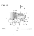
- One or more build-up portions 148 of a bracket 140 of the second embodiment are provided with one or more cut portions (an example of the "first engaging portion") 147 substantially extending in the width direction WD instead of the screw holes.
- the cut portion(s) 147 is/are recessed forward from the rear end surfaces of the build-up portions 148.
- the plurality of (e.g. four) cut portions 147 are shaped to substantially coincide in the width direction WD.
- one or more first locking portions 157 of the second embodiment are formed to cover the build-up portions 148 from above and/or at least partly enter the cut portions 147 from behind.
- the first locking portions 157 lock the cut portions 147 from below.
- the cut portions 147 of this embodiment particularly can be respectively formed in the build-up portions 148 by cutting the build-up portion(s) 148 straight in the width direction, for example, using a cutting tool such as a T-shaped cutter. This can simplify the cutting process as compared with the case where the cut portions are individually vertically cut, for example, using a drill or the like.
Landscapes
- Engineering & Computer Science (AREA)
- Manufacturing & Machinery (AREA)
- Connections Arranged To Contact A Plurality Of Conductors (AREA)
Abstract
Description
- The present invention relates to a terminal block and to an assembling method therefor.
- Conventionally, a terminal block disclosed in Japanese Unexamined Patent Publication No.
H11-144783 - According to such a terminal block, heat generated from conductive members such as terminals is transferred to the nut and accumulated in the terminal block. Thus, it has been attempted to arrange a metal bracket fixed to a case of a motor below the nut via an insulating sheet, integrally fix these three members by a resin portion, transfer heat transferred from the conductive members to the nut to the bracket via the insulating sheet and radiate this heat from the bracket to the case of the motor.
- Further, the bracket needs to be directly in contact with the case to radiate the heat from the bracket to the case, and it is necessary to reduce a covered part of the bracket by the resin portion. However, if the covered part of the bracket is small, the resin portion is pulled toward the bolt together with the nut and the resin portion and the bracket are separated at the time of bolt tightening.
- The present invention was completed in view of the above situation and an object thereof is to prevent the separation of a bracket and a resin portion while improving a heat radiation property of the bracket.
- This object is solved according to the invention by the features of the independent claims. Particular embodiments of the invention are subject of the dependent claims.
- According to one aspect of the invention, there is provided a terminal block for connecting a conductive member extending from a device and a mating conductive member, including a fastening seat on which the conductive member and the mating conductive member at least partly are to be placed (particularly substantially from above or in a mounting direction) and which fastens the conductive member and the mating conductive member together with a bolt; a bracket which is made of metal and arranged adjacent to the fastening seat (particularly substantially below the fastening seat); and a resin portion which integrally fixes the fastening seat and the bracket by covering a part of the fastening seat together with the bracket; wherein the bracket includes at least one mounting portion at least partly exposed (particularly substantially fully exposed) from the resin portion and to be directly fixed to a metal case for housing the device, and at least one embedded portion embedded in the resin portion; and the resin portion includes a first locking portion for locking a first engaging portion provided on the mounting portion (particularly substantially from below) and a second locking portion for locking a second engaging portion provided on the embedded portion (particularly substantially from below).
- According to the thus configured terminal block, heat of the bracket can be radiated to the metal case from the mounting portion directly fixed to the metal case. Further, when the bolt is tightened into the fastening seat, the resin portion is pulled (e.g. substantially upward) together with the fastening seat and the bracket fixed to the case may be separated from the resin portion. However, since the second engaging portion of the embedded portion is locked (particularly substantially from below) by the second locking portion of the resin portion according to the above configuration, the separation of the bracket and the resin portion can be prevented at the embedded portion side.
- Further, since the first engaging portion of the mounting portion is locked (particularly substantially from below) by the first locking portion of the resin portion, the separation of the bracket and the resin portion can be prevented at the mounting portion side. Specifically, it is possible to prevent the separation of the bracket and the resin portion while improving a heat radiation property from the bracket to the case.
- According to a particular embodiment, a plurality of the fastening seats are arranged substantially in a width direction intersecting with an extending direction of the conductive member.
- Particularly, the resin portion includes nut locking portions for locking outer peripheral edge parts of the fastening seats, and wherein at least one partition wall for partitioning between adjacent fastening seats is provided between adjacent ones of the nut locking portions while being connected to the nut locking portions.
- Further particularly, the first locking portion is provided on an end part of the partition wall.
- Further particularly, a plurality of the fastening seats may be arranged in a width direction intersecting with an extending direction of the conductive member; the resin portion may include nut locking portions for locking outer peripheral edge parts of the fastening seats from above; a partition wall for partitioning between adjacent fastening seats may be provided between adjacent ones of the nut locking portions while being connected to the nut locking portions; and the first locking portion may be provided on an end part of the partition wall.
- According to such a configuration, the separation of the bracket and the resin portion can be prevented by supporting two adjacent nut locking portions by one first locking portion. This can simplify the structure of the mounting portion side by reducing the number of the first locking portions as compared with the case where the first locking portion is formed for each nut locking portion.
- Further particularly, the lower surface of the mounting portion fixed to the case is recessed upwardly to form at least one heat radiation recess for radiating heat of the bracket by taking in coolant for cooling the interior of the case.
- Further particularly, the first engaging portion is formed by cutting a built-up portion provided above the heat radiation recess.
- Further particularly, the lower surface of the mounting portion fixed to the case may be recessed upwardly to form a heat radiation recess for radiating heat of the bracket by taking in coolant for cooling the interior of the case; and the first engaging portion may be formed by cutting a built-up portion provided above the heat radiation recess.
- For example, if it is attempted to form the first engaging portion above the heat radiation recess by cutting without providing the mounting portion with the build-up portion, a side of the mounting portion above the heat radiation recess becomes thinner. Thus, the first engaging portion cannot be formed. However, since the first engaging portion is formed by cutting the build-up portion provided on top of the mounting portion according to the above configuration, the heat radiation recess and the first engaging portion can be vertically provided one above the other on the mounting portion. This can prevent the enlargement of the mounting portion as compared with the case where the mounting portion and the heat radiation recess are formed without being arranged one above the other.
- Further particularly, the first engaging portion may comprise (particularly be formed as) a screw hole including a screw groove on an inner peripheral surface.
- According to such a configuration, the first locking portion of the resin portion can firmly lock the screw groove.
- Further particularly, a plurality of the first engaging portions may be arranged in a width direction intersecting with an extending direction of the conductive member; and the plurality of the first engaging portions may include one or more cut portions arranged to substantially coincide in a width direction.
- According to such a configuration, the cutting portion can be formed in each of the plurality of first engaging portions by cutting the mounting portion in the width direction using a cutting tool such as a cutter. This can simplify a cutting process as compared with the case where the mounting portion is cut to individually form the cut portions, for example, using a cutting tool such as a drill.
- Further particularly, at least one guiding portion provided adjacent to the fastening seat and configured to guide the conductive member to the fastening seat by coming into contact with a lateral edge part of the conductive member; and/or one or more posture correcting portions provided at one or more positions where the conductive member(s) is/are pulled out to outside from the fastening seat(s) and configured to correct posture(s) of the conductive member(s) in a width direction by coming into contact with the conductive member(s) pulled out to the outside from the fastening seat(s) in the width direction.
- Further particularly, the conductive member includes a bolt fastening portion to be placed on the fastening seat in a mounting direction and a wire fixing portion to be fixed to an end of a wire, wherein the guiding portion particularly is formed to project adjacent to the bolt fastening portion, particularly to stand between adjacent bolt fastening portions; and/or wherein the posture correcting portion(s) particularly is/are formed to stand upward from the bracket to be arranged adjacent to the wire fixing portion, particularly at least partly between the wire fixing portions.
- According to another aspect of the invention, there is provided a method of assembling (i.e. producing) a terminal block, in particular according to the above aspect of the invention or a particular embodiment thereof, to connect one or more conductive members extending from a device and one or more respective mating conductive members, comprising: at least partly placing the conductive member and the mating conductive member on a fastening seat; fastening the conductive member and the mating conductive member together with a bolt; a bracket which is made of metal and arranged adjacent to the fastening seat; and integrally fixing the fastening seat and the bracket by means of a resin portion covering a part of the fastening seat together with the bracket; wherein the bracket includes at least one mounting portion at least partly exposed from the resin portion and to be directly fixed to a metal case for housing the device, and at least one embedded portion embedded in the resin portion; and wherein the resin portion includes a first locking portion for locking a first engaging portion provided on the mounting portion and a second locking portion for locking a second engaging portion provided on the embedded portion.
- According to a particular embodiment, a plurality of the fastening seats are arranged substantially in a width direction intersecting with an extending direction of the conductive member.
- Particularly, the method further comprises locking outer peripheral edge parts of the fastening seats by means of nut locking portions of the resin portion, and providing at least one partition wall for partitioning between adjacent fastening seats between adjacent ones of the nut locking portions while being connected to the nut locking portions.
- Further particularly, the first locking portion is provided on an end part of the partition wall.
- Further particularly, the lower surface of the mounting portion fixed to the case is recessed upwardly to form at least one heat radiation recess for radiating heat of the bracket by taking in coolant for cooling the interior of the case, and wherein the first engaging portion particularly is formed by cutting a built-up portion provided above the heat radiation recess.
- According to the present invention, it is possible to prevent the separation of a bracket and a resin portion while improving a heat radiation property of the bracket.
- These and other objects, features and advantages of the present invention will become more apparent upon reading of the following detailed description of preferred embodiments and accompanying drawings. It should be understood that even though embodiments are separately described, single features thereof may be combined to additional embodiments.
-
FIG. 1 is a perspective view of a terminal block in a first embodiment, -
FIG. 2 is a front view of the terminal block, -
FIG. 3 is a plan view of the terminal block, -
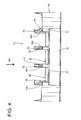
FIG. 4 is a rear view of the terminal block, -
FIG. 5 is a bottom view of the terminal block, -
FIG. 6 is a section along VI-VI ofFIG. 3 , -
FIG. 7 is an enlarged section of an essential part ofFIG. 6 , -
FIG. 8 is a perspective view showing a state where busbars and terminals are bolted in proper postures, -
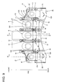
FIG. 9 is a plan view showing the state ofFIG. 8 , -
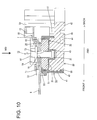
FIG. 10 is a section along X-X ofFIG. 9 , -
FIG. 11 is a section along XI-XI ofFIG. 9 , -
FIG. 12 is a section along XII-XII ofFIG. 9 , -
FIG. 13 is a perspective view showing a state where the busbar and the rotated terminal are bolted, -
FIG. 14 is a perspective view of a bracket, -
FIG. 15 is a plan view of the bracket, -
FIG. 16 is a section, equivalent toFIG. 6 , in a second embodiment, -
FIG. 17 is a perspective view of a bracket, and -
FIG. 18 is a plan view of the bracket. - A first particular embodiment of the present invention is described with reference to
FIGS. 1 to 15 .
In this embodiment is illustrated aterminal block 10 which is to be mounted in or to a mounting device such as a motor case (not shown) installed in a vehicle such as an electric vehicle or a hybrid vehicle and electrically connects one or more (e.g. three) terminals (an example of a "conductive member") T connected to one or more respective enameled wires (not shown) extending from a connection device, e.g. extending from a three-phase AC motor housed in the motor case, and one or more respective (e.g. three) busbars (an example of a "mating conductive member") B extending from the connection device, e.g. from an inverter. Note that, in the following description, a vertical direction is based on that inFIG. 2 , forward and backward directions are based on a vertical direction ofFIG. 9 , and a side where the busbars B are arranged (shown upper side) is referred to as a front side. - As shown in
FIGS. 10 and11 , theterminal block 10 is provided with one or more, particularly a plurality of nuts (an example of a "fastening seat") 20 on which the busbar(s) B and the terminal(s) T are to be placed in a mounting direction MD or laterally (e.g. from above), abracket 40 arranged below or adjacent to the nuts 20, an insulatingplate 30 arranged between the nuts 20 and thebracket 40, and/or aresin portion 50 for integrally fixing these. - The busbar B particularly substantially is in the form of a flat plate and/or formed with a vertically penetrating (penetrating in the mounting direction MD) bolt insertion hole B1 at a position to be at least partly placed on the
nut 20. - As shown in
FIGS. 8 to 10 , the terminal T includes a bolt fastening portion T1 (particularly substantially in the form of a flat plate) to be placed on thenut 20 and a barrel portion T2 to which one or more, particularly a plurality of enameled wires are to be connected, and a connecting part between the bolt fastening portion T1 and the barrel portion T2 particularly are so cranked that the barrel portion T2 is arranged above (on a different level or offset or plane as compared to) the bolt fastening portion T1. The bolt fastening portion T1 is formed with a vertically penetrating (penetrating in the mounting direction MD) bolt insertion hole T3. Further, the barrel portion T2 is particularly substantially in the form of an elliptical tube laterally long in the width direction WD, and/or substantially opposite widthwise end parts are rounded. - The
nut 20 is made of conductive material such as metal and, as shown inFIG. 3 , particularly has a substantially rectangular plan view and abolt fastening hole 21 into which a bolt BT is to be tightened is provided in an intermediate part (particularly substantially in a central part) of thenut 20. Further specifically, a plurality of (five in this embodiment) nuts 20 are arranged in the width direction WD. The bolt fastening portion T1 of the terminal T for power source and the busbar B at least partly are placed one over the other on the respective nut(s) 20, particularly on each of the threemiddle nuts 20, the bolt BT is inserted through the bolt fastening hole T3 of the bolt fastening portion T1 and the bolt insertion hole B1 of the busbar B and tightened into thebolt fastening hole 21 of thenut 20, whereby the terminal T and the busbar B are fastened together and electrically connected by the bolt BT and thenut 20 as shown inFIG. 10 . - Further, the bolt fastening portion T1 of the terminal T for neutral point particularly is placed on each of the nuts 20 on the opposite sides from above, the bolt BT is inserted through the bolt insertion hole T3 of the bolt fastening portion T1 and tightened into the
bolt fastening hole 21 of thenut 20, whereby the terminal T for neutral point is bolted to thenut 20 as shown inFIG. 11 . - Further, when the bolt fastening portion T1 of each terminal T is fixed to the
nut 20, the barrel portion T2 (as a particular wire fixing portion) of the terminal T is arranged behind (or adjacent or offset from) thenut 20. - A stepped
portion 22 particularly is formed over at least part of, particularly over the substantially entire circumference on an upper or distal outer peripheral edge part of eachnut 20. As shown inFIGS. 10 and11 , this steppedportion 22 is slightly lower than the upper surface of thenut 20 and at least partly covered by anut locking portion 52 of theresin portion 50 to be described later from above. - The insulating
plate 30 particularly is made of a highly heat conductive synthetic resin containing glass or talc and/or vertically sandwiched by the nuts 20 and thebracket 40 as shown inFIGS. 10 and11 . Abottom plate 31 arranged between the nut(s) 20 and thebracket 40 particularly substantially is in the form of a thin flat plate, the lower surface(s) of the nut(s) 20 particularly is/are held in close contact with the upper surface of thebottom plate 31, and/or the upper surface of thebracket 40 is held in close contact with the lower surface of thebottom plate 31. Thus, heat of the nut(s) 20 is efficiently transferred to thebracket 40 via the insulatingplate 30. - Further, the
bottom plate 31 of the insulatingplate 30 is provided with one or more, particularly a plurality ofbolt escaping recesses 32 which particularly are bottomed recesses projecting downward. The (particularly each)bolt escaping recess 32 is provided to substantially correspond to thebolt fastening hole 21 of thenut 20 arranged on the upper surface of the insulatingplate 30, and prevents the interference of the bolt BT and the insulatingplate 30 by allowing the tip of the bolt BT to escape when the bolt BT is tightened into thenut 20. - The
bracket 40 particularly is formed by aluminum die casting and, as shown inFIGS. 14 and15 , laterally long in the width direction WD and/or the rear surface of thebracket 40 is formed into a substantially arcuate or bent shape substantially in conformity with the shape of the motor case. As shown inFIGS. 10 and11 , thebracket 40 includes an embeddedportion 41 on which the insulatingplate 30 is to be placed and/or which at least partly is covered by theresin portion 50, and a mountingportion 42 which is connected behind the embeddedportion 41 and/or exposed from theresin portion 50. - The insulating
plate 30 is so to be placed on the upper or outer surface of the embeddedportion 41 as to cover substantially the entire upper surface of the embeddedportion 41. Further, one or more, particularly a plurality offitting recesses 43, into which the bolt escaping recess(es) 32 of the insulatingplate 30 at least partly is/are fittable, are provided (particularly substantially side by side in the width direction WD) on the upper surface of the embeddedportion 41. The insulatingplate 30 particularly is to be mounted on the upper surface of the embeddedportion 41 without being displaced by fitting the bolt escaping recess(es) 32 into this/these fitting recess(es) 43. - As shown in
FIGS. 10 and15 , the mountingportion 42 is provided on (particularly a lower rear end edge of) the embeddedportion 41 and/or to be fixed to an attaching portion (not shown) provided on the motor case. As shown inFIG. 3 , one or more vertically penetrating throughholes 42A are provided on (particularly substantially opposite widthwise sides of) the mountingportion 42. By inserting one or more fixing bolts (not shown) through this/these through hole(s) 42A and tightening it/them into the attaching portion, thebracket 40 is or can be fixed to the motor case and theterminal block 10 is or can be mounted and fixed to the motor case. - As shown in
FIGS. 5 and6 , at least one heat radiation recess 44 (particularly substantially arcuately extending in the width direction WD) is formed on (particularly the lower surface of) the mountingportion 42. Thisheat radiation recess 44 particularly is recessed upwardly and at least one cooling fin 45 (particularly substantially projecting downward) is provided on or near the back wall of theheat radiation recess 44. When the mountingportion 42 is fixed to the attaching portion of the motor case, coolant circulating in the motor case can circulate substantially in the width direction WD in theheat radiation recess 44 and heat of thebracket 40 is efficiently radiated from the coolingfin 45. - Further, a (particularly substantially rectangular)
gate mark 46, which is a fracture mark of an aluminum die casting material, is formed on the rear surface of the mountingportion 42 when a molding die is opened (seeFIG. 2 ). Note that although not shown, fine edges formed when the aluminum die casting material is fractured may be left on an outer peripheral edge part of thegate mark 46 in some cases. - The
resin portion 50 is made of synthetic resin and, as shown inFIGS. 10 and11 , integrally fixes the one ormore nuts 20, the insulatingplate 30 and thebracket 40 while vertically holding them one over another in close contact by at least partly covering parts of these members. Theresin portion 50 includes amain body portion 51 which particularly collectively covers the side surface(s) of the respective nut(s) 20, those of the insulatingplate 30 and those of the embeddedportion 41. - The (particularly substantially rectangular)
nut locking portion 52 for locking the steppedportion 22 of thenut 20 together with the insulatingplate 30 from above is provided for eachnut 20 on (particularly an upper part of) themain body portion 51. Thenut locking portion 52 locks the steppedportion 22 of the nut 20 (particularly substantially from above) to prevent a clearance from being formed between thenut 20 and the insulatingplate 30 when the bolt BT is tightened into thebolt fastening hole 21 of thenut 20 and thenut 20 is pulled upward. - As shown in
FIGS. 3 and4 , one ormore partition walls 53 partitioning betweenadjacent nuts 20 are respectively provided between adjacentnut locking portions 52. Specifically, two or more (e.g. four)partition walls 53 are arranged substantially side by side in the width direction WD. Thesepartition walls 53 are formed to stand upward from themain body portion 51 and/or extend over the entire length of themain body portion 51 in forward and backward directions FBD. The height of thepartition wall 53 particularly is set to be larger than the sum of the thickness of the bolt fastening portion T1 of the terminal T and that of the busbar B placed on thenut 20 as shown inFIG. 10 . This can ensure a distance at which insulation is maintained between adjacent bolt fastening portions T1 and between adjacent busbars B, i.e. a so-called insulation distance (creepage distance). - As shown in
FIGS. 3 and4 , at least one guidingportion 54 for substantially guiding the busbar B and/or the terminal T with respect to thenut 20, particularly to the upper surface of thenut 20, is provided in an intermediate part (particularly substantially in a central part) of an upper end part of the (particularly each)partition wall 53 in forward and backward directions FBD. The guidingportion 54 is formed to have a converging or pointed shape (particularly a substantially triangular shape) long in forward and backward directions FBD and particularly includingoblique surfaces 54A on substantially opposite widthwise sides. This causes (particularly substantially opposite widthwise side edges of) the busbar B and the bolt fastening portion T1 to come into contact with the oblique surface(s) 54A of the guiding portion(s) 54, whereby the busbar B and/or the bolt fastening portion T1 are guided (or oriented or relatively positioned with respect to the nut 20) and at least partly placed onto the upper surface of thenut 20 even if the busbar B and/or the bolt fastening portion T1 of the terminal T are slightly displaced in the width direction WD in placing the busbar B and the terminal T on the upper surface (as a particular arrangement surface) of thenut 20 in the mounting direction MD or substantially from above. - As shown in
FIGS. 1 and3 , at least one (particularly substantially plate-like)posture correcting portion 55 substantially extending backward from the rear end surfaces of themain body portion 51 and/or thepartition wall 53 particularly is provided on a rear end part of eachpartition wall 53. Fourposture correcting portions 55 particularly substantially are arranged in the width direction WD similarly to thepartition walls 53. - The
posture correcting portions 55 are formed to stand upward or project along the mounting direction MD from the distal or upper surface of the mountingportion 42 and one or more crankportions 55A substantially bent toward the center are formed at positions, near the partition walls, of theposture correcting portions 55 arranged on (particularly substantially opposite widthwise sides out of) the (particularly four) posture correcting portion(s) 55 as shown inFIG. 3 . - As shown in
FIG. 9 , the barrel portions T2 of the terminals T placed on the nuts 20 particularly are arranged at substantially opposite widthwise sides of theposture correcting portions 55 with clearances defined in the width direction WD therebetween. As shown inFIGS. 10 and11 , the height of theposture correcting portion 55 particularly is set to be larger than that of the barrel portion T2 located on a rear part of the terminal T, and/or a rear end part thereof extends more backward than that of the barrel portion T2. When the terminals T are placed on the nuts 20, theposture correcting portions 55 particularly block between the barrel portions T2 of adjacent terminals T to ensure a creepage distance (insulation distance) between adjacent barrel portions T2. - Further, if the terminal T is placed on the
nut 20 in the mounting direction MD (particularly substantially from above) with the barrel portion T2 thereof displaced in the width direction WD, theposture correcting portion 55 comes into contact with a lateral edge of the barrel portion T2 in the width direction, whereby the posture of the barrel portion T2 in the width direction WD is corrected to a substantially proper posture (posture in which the terminal T particularly is straight in forward and backward directions FBD). When the terminal(s) T is/are placed on the nut(s) 20, the (particularly substantially adjacent) barrel portion(s) T2 is/are blocked by the posture correcting portion(s) 55 and specifically the creepage distance (insulation distance) between the barrel portions T2 is ensured even if the adjacent barrel portions T2 are slightly displaced in the width direction WD as shown inFIG. 13 . - Furthermore, even if the terminal T rotates, following the rotation of the bolt BT, in tightening the bolt BT into the
nut 20, theposture correcting portion 55 comes into contact with the barrel portion T2 in the width direction WD, thereby preventing the terminal T from being largely rotated and particularly ensuring the creepage distance (insulation distance) between the adjacent barrel portions T2. - At least one projecting
portion 56 for reinforcing theposture correcting portion 55 particularly is provided to project substantially in the width direction WD on (particularly a rear end part of) the (particularly each)posture correcting portion 55. The projectingportion 56 particularly is formed over the entire height of theposture correcting portion 55 and set to be arranged behind the barrel portion T2 of the terminal T mounted in a proper posture on thenut 20. - The projecting
portion 56 particularly is provided on each of opposite widthwise sides of each of the twoposture correcting portions 55 arranged in the middle or intermediate position out of theposture correcting portions 55 so as to prevent theposture correcting portion 55 from being inclined in the width direction WD to be broken when a force acts on theposture correcting portion 55 in the width direction WD. Further, the projectingportion 56 particularly is provided on each of the twoposture correcting portions 55 arranged on substantially opposite widthwise sides out of theposture correcting portions 55 to project toward the center, and reinforces theposture correcting portion 55 particularly together with thecrank portion 55A of theposture correcting portion 55. That is, similarly to theposture correcting portions 55 arranged in the middle or intermediate position, the twoposture correcting portions 55 arranged on the substantially opposite widthwise sides can prevent theposture correcting portions 55 from being inclined in the width direction WD to be broken when a force acts on theposture correcting portions 55 in the width direction WD. - To prevent the posture correcting portion from being inclined in the width direction WD, it particularly is thought to increase the strength of the posture correcting portion in the width direction WD by setting the thickness of the entire posture correcting portion equal to that of the part of the posture correcting portion where the projecting portion(s) is/are provided. If the thickness of the entire posture correcting portion is increased, the clearance between the posture correcting portion and the barrel portion becomes smaller. In placing the
nut 20 on the terminal T, even a slight displacement of the terminal T in the width direction WD may cause the barrel portion T2 to move onto the posture correcting portion. However, since the clearance between theposture correcting portion 55 and the barrel portion T2 particularly is made larger by thinning theposture correcting portion 55 except at the part where the projecting portion(s) 56 is/are provided according to this embodiment, the barrel portion T2 can be easily arranged between theposture correcting portions 55 even if the terminal T is slightly displaced in the width direction WD when being placed on thenut 20. This can improve mounting operability in placing the terminal T on thenut 20. - For example, the creepage distance between the barrel portions of adjacent terminals T may become shorter if the bolt insertion hole T3 of the bolt fastening portion T1 is large relative to the bolt BT and the terminal T is bolted in a state slightly displaced backward. However, according to this embodiment, if the terminal T is displaced backward, the projecting portion(s) 56 particularly can come into contact with the barrel portion T2 in the width direction and the posture of the terminal T can be corrected to approach a proper posture (posture in which the terminal T substantially is straight in forward and backward directions FBD). This can reliably ensure the creepage distance (insulation distance) between the barrel portions T2.
- Specifically, since the projecting
portion 56 of this embodiment particularly has two functions of a reinforcing function of reinforcing theposture correcting portion 55 and a posture correcting function of correcting the posture of the terminal T, it can be suppressed that the structure of theposture correcting portion 55 becomes complicated, as compared with the case where each posture correcting portion has the reinforcing function and the posture correcting function. - A
first locking portion 57 to be engaged with a (particularly bottomed) screw hole (an example of a "first engaging portion") 47 provided on the mountingportion 42 is provided on or near a lower end part of theposture correcting portion 55. - The
screw hole 47 of the mountingportion 42 includes ascrew groove 47A on the inner peripheral surface and is formed by recessing the upper surface of a (particularly substantially cylindrical) build-upportion 48 projecting from (particularly the upper surface of) the mountingportion 42. - As shown in
FIG. 7 , thefirst locking portion 57 at least partly enters thescrew hole 47 of the mountingportion 42 and thescrew groove 47A of thescrew hole 47 by covering the build-upportion 48 of the mountingportion 42. When an upward pulling force acts on theresin portion 50, thefirst locking portion 57 particularly locks anupper end 47B of thescrew groove 47A from below. This can prevent themain body portion 51 of theresin portion 50 and the embeddedportion 41 of thebracket 40 from being separated at a rear end side of theresin portion 50 when the bolt BT is tightened into thebolt fastening hole 21 of thenut 20 and theresin portion 50 is pulled upward together with thenut 20. - Further, the
first locking portions 57 and the screw holes 47 particularly are arranged substantially between adjacentnut locking portions 52, and twonut locking portions 52 are supported by onefirst locking portion 57 and onescrew hole 47. That is, e.g. fivenut locking portions 52 are supported by fourfirst locking portions 57 and e.g. four screw holes 47 on the rear end side of theresin portion 50 and the numbers of thefirst locking portions 57 and the screw holes 47 can be reduced as compared with the case where the first locking portion is formed for each nut locking portion. This can prevent thebracket 40 and theresin portion 50 from being separated while simplifying the structure of the rear end side of theresin portion 50. - Further, the screw holes 47 particularly are arranged in correspondence with or substantially above the
heat radiation recess 44 of the mountingportion 42 and formed in the build-upportions 48 provided on top of the mountingportion 42, whereby a sufficient thickness is ensured between theheat radiation recess 44 and the screw holes 47. - Although a screw hole is formed by cutting using a drill or the like, it is generally not possible to form a screw groove with a tip part of the drill. Hence, the depth of the screw hole is larger than the height of a part where the screw groove is provided. Thus, if it is attempted to form a screw hole with a predetermined dimension of a screw groove ensured above a heat radiation recess without providing a build-up portion on a mounting portion, a sufficient thickness cannot be ensured between the heat radiation recess and the screw hole and the screw hole cannot be provided above the heat radiation recess. However, since the
screw hole 47 particularly is formed in the build-upportion 48 provided on top of the mountingportion 42 according to the above configuration, theheat radiation recess 44 and thescrew hole 47 can be vertically formed one above the other on the mountingportion 42 while ensuring a sufficient thickness between theheat radiation recess 44 and thescrew hole 47. This can prevent the enlargement of the mountingportion 42, for example, as compared with the case where the mounting portion and the heat radiation recess are displaced in forward and backward directions. - On the other hand, as shown in
FIGS. 6 ,10 and11 , asecond locking portion 58 for locking an engaging portion (an example of a second engaging portion) 49 connected to (particularly a lower outer peripheral edge part of) the embeddedportion 41 and/or opposite lower lateral edge parts of the mountingportion 42 from below particularly is provided on (particularly a lower end part of) themain body portion 51. - The engaging
portion 49 particularly is stepped or enlarged to be slightly raised from the lower surface of thebracket 40 and/or slightly recessed inwardly of the outer peripheral surfaces of the embeddedportion 41 and the mountingportion 42. - The
second locking portion 58 particularly is formed on an outer peripheral edge part of themain body portion 51 except at a front edge part of themain body portion 51 so as to substantially correspond to the engagingportion 49, and at least partly covers the engagingportion 49 from below. That is, as shown inFIG. 5 , thesecond locking portion 58 particularly substantially is U-shaped in bottom view and arranged to surround the embeddedportion 41 particularly over the substantially entire circumference together with thefirst locking portions 57 of themain body portion 51. - Specifically, the first and
second locking portions main body portion 51 lock thebracket 40 from below in such a manner as to surround the embeddedportion 41 particularly over the substantially entire circumference and reliably prevent theresin portion 50 and thebracket 40 from being vertically separated. - To prevent the separation of a resin portion and a bracket, it is thought to provide a stepped engaging portion over the entire circumference on a lower outer peripheral edge part of the bracket and lock the engaging portion over the entire circumference from below by a locking portion of a main body portion by at least partly covering the side surfaces of the bracket and the engaging portion over the entire circumference by the resin portion. However, a heat radiation property of the bracket may be reduced if the side surfaces of the bracket are covered over the entire circumference with resin. Further, the
gate mark 46 formed when thebracket 40 is formed by die casting may be left on the rear surface of the mountingportion 42. If thatgate mark 46 is covered with resin, the resin portion may be broken, such as due to the formation of cracks from fine edge parts formed on an outer peripheral edge part of thegate mark 46. - However, since the mounting
portion 42 particularly is exposed from theresin portion 50 according to this embodiment, it is possible to prevent the breakage of theresin portion 50 while improving a heat radiation property of thebracket 40. - The
terminal block 10 of this embodiment is configured as described above. Next, how to assemble the busbars B and the terminals T with theterminal block 10 is briefly described and functions and effects of theterminal block 10 are described. - First, the busbars B extending from the connection device (such as the inverter) are placed on the upper surfaces (mounting surfaces) of the
nuts 20 of theterminal block 10 mounted and fixed to the mounting device (such as the motor case) and, then, the terminals T connected to ends of the enameled wires extending from the mounting device (particularly the motor) at least partly are placed on the busbars B. - Here, even if the busbars B are slightly displaced in the width direction WD when the one or more, particularly the plurality of (e.g. three) busbars B are placed on the nut(s) 20 in the mounting direction MD, particularly substantially from above, the lateral edge part(s) of the busbar(s) B come into contact with the oblique surface(s) 54A of the guiding portion(s) 54 and the busbar(s) B is/are guided and placed onto the upper surface(s) of the nut(s) 20. Further specifically, even if three terminals T are slightly displaced in the width direction WD, the lateral edge parts of the bolt fastening portions T1 of the terminals T come into contact with the oblique surfaces 54A of the guiding
portions 54 and the terminals T are guided and placed onto the upper surfaces of the nuts 20 similarly to the busbars B. - Further, in the case of the terminal T, even if the barrel portion T2 is displaced in the width direction WD such as due to the rotational displacement of the terminal T in the width direction WD, the
posture correcting portion 55 comes into contact with the lateral edge of the barrel portion T2 in the width direction WD (or in a direction at an angle different from 0° or 180°, preferably substantially perpendicular to the mounting direction MD), whereby the posture of the barrel portion T2 in the width direction WD is corrected and/or the terminal T is placed on thenut 20 in a state particularly where adjacent barrel portions T2 are blocked by theposture correcting portion 55. - Specifically, according to this embodiment, the busbar B and the terminal T can be guided onto the
nut 20 by the guidingportion 54 and/or the posture of the barrel portion T2 of the terminal T can be corrected by theposture correcting portion 55 when the busbar B and the terminal T at least partly are placed on thenut 20. This enables the terminal T and the busbar B to be reliably placed on thenut 20 particularly while ensuring the creepage distance (insulation distance) between adjacent barrel portions T2. - Since the
posture correcting portion 55 particularly corrects the posture of the terminal T by coming into contact with the barrel portion T2 of the terminal T, it is necessary to prevent theposture correcting portion 55 from being inclined in the width direction WD to be broken. It is thought to increase the thickness of the entire posture correcting portion to prevent the inclination of the posture correcting portion. However, if the thickness of the posture correcting portion is increased, the clearance between the posture correcting portion and the barrel portion becomes smaller and even only a slight displacement of the terminal T in the width direction WD may cause the terminal T to move onto the posture correcting portion, whereby operability in mounting the terminal T on thenut 20 is reduced. - However, since the projecting portion(s) 56 particularly is/are provided only on the rear end part of each
posture correcting portion 55 and a part of theposture correcting portion 55 where the barrel portion T2 is to be arranged is made thinner according to this embodiment, the barrel portion T2 can be easily at least partly arranged between adjacentposture correcting portions 55 even in a state where the barrel portion T2 is slightly displaced in the width direction WD. This can improve operability in mounting the terminal T on thenut 20 while ensuring the strength of theposture correcting portion 55 in the width direction WD, as compared with the case where the thickness of the entire posture correcting portion is increased. - Subsequently, the bolt BT is inserted through the busbar B and the bolt insertion hole T3 of the bolt fastening portion T1 and tightened into the
bolt fastening hole 21 of thenut 20. - Here, in tightening the bolt BT into the
nut 20, the terminal T may rotate, following the rotation of the bolt BT. However, according to this embodiment, if the terminal T tries to rotate, theposture correcting portion 55 particularly comes into contact with the barrel portion T2 in the width direction WD, thereby being able to prevent the terminal T from largely rotating. - Further, in case of plural terminals T, a distance between adjacent terminals T may become shorter and the creepage distance (insulation distance) cannot be ensured, for example, if the bolt insertion hole T3 of the bolt fastening portion T1 is large relative to the bolt BT and the terminal T is slightly displaced backward. However, according to this embodiment, the projecting
portions 56 particularly can come into contact with the barrel portion T2 in the width direction WD and the posture of the terminal T can be corrected to approach the proper posture (posture in which the terminal T is straight in forward and backward directions FBD) if the terminal T is displaced backward. This can reliably ensure the creepage distance (insulation distance) between the barrel portions T2. - When the bolt BT is completely tightened into the
bolt fastening hole 21 of thenut 20, the busbar B and the bolt fastening portion T1 are fastened together and electrically connected by the bolt BT and thenut 20. - In the process of tightening the bolt BT into the
nut 20, theresin portion 50 is pulled upward together with thenut 20 and thebracket 40 fixed to the mounting device (e.g. the motor case) and theresin portion 50 may be separated. - However, according to this embodiment, the
first locking portions 57 particularly lock the upper end(s) 47B of the screw groove(s) 47A in the screw hole(s) 47 provided on the mountingportion 42 from below on the rear edge of themain body portion 51 of theresin portion 50 and/or thesecond locking portion 58 particularly locks the engagingportion 49 from below on the front edge and the opposite widthwise side edges of thebracket 40. Specifically, since the first andsecond locking portions main body portion 51 of theresin portion 50 particularly lock the embeddedportion 41 from below in such a manner as to surround the embeddedportion 41 particularly over the substantially entire circumference, the separation of thebracket 40 and theresin portion 50 can be reliably prevented. - Specifically, according to this embodiment, it is possible to prevent the separation of the
bracket 40 and theresin portion 50 while improving the heat radiation property from the lower surfaces of the mountingportion 42 and thebracket 40 exposed from theresin portion 50. - Accordingly, to prevent the separation of a bracket and a resin portion while improving a heat radiation property of the bracket, a
terminal block 10 is for connecting one or more terminals T connected to one or more ends of one or more respective enameled wires extending from a mounting device (such as a motor) and one or more busbars B extending from a connecting device (such as an inverter) and includes one ormore nuts 20 on which the one or more terminals T and the one or more busbars B are to be at least partly placed in the mounting direction MD (particularly substantially from above) and which fasten(s) the terminal(s) T and the busbar(s) B together with bolt(s) BT, abracket 40 which particularly is formed by aluminum die casting and arranged below the nut(s) 20, and aresin portion 50 which integrally fixes the nut(s) 20 and thebracket 40. Thebracket 40 includes at least one mountingportion 42 at least partly exposed from theresin portion 50 and to be directly fixed to a case of the mounting device (e.g. directly fixed to a metal motor case), and an embeddedportion 41 embedded in theresin portion 50. Theresin portion 50 includes one or morefirst locking portions 57 for locking one ormore screw grooves 47A of one or more screw holes 47 provided on the mounting portion 42 (particularly substantially from below), and at least onesecond locking portion 58 for locking at least one engagingportion 49 provided on the embedded portion 41 (particularly substantially from below). - Next, a second particular embodiment of the present invention is described with reference to
FIGS. 16 to 18 . - In a
terminal block 11 of the second embodiment, the shapes of the build-upportions 48 and thefirst locking portions 57 of the first embodiment are changed. Configurations, functions and effects similar or common to the first embodiment are not repeatedly described. Further, the similar or same components as those of the first embodiment are denoted by the same reference signs. - One or more build-up
portions 148 of abracket 140 of the second embodiment are provided with one or more cut portions (an example of the "first engaging portion") 147 substantially extending in the width direction WD instead of the screw holes. The cut portion(s) 147 is/are recessed forward from the rear end surfaces of the build-upportions 148. When viewed in the width direction WD, the plurality of (e.g. four) cutportions 147 are shaped to substantially coincide in the width direction WD. - On the other hand, one or more
first locking portions 157 of the second embodiment are formed to cover the build-upportions 148 from above and/or at least partly enter thecut portions 147 from behind. When aresin portion 50 is pulled upward, thefirst locking portions 157 lock thecut portions 147 from below. - In the case of forming vertically recessed cut portions in build-up portions, it is thought to individually form the cut portions in the respective build-up portions, for example, using a cutting tool such as a drill, but as many cutting processes as the build-up portions are necessary.
- However, the
cut portions 147 of this embodiment particularly can be respectively formed in the build-upportions 148 by cutting the build-up portion(s) 148 straight in the width direction, for example, using a cutting tool such as a T-shaped cutter. This can simplify the cutting process as compared with the case where the cut portions are individually vertically cut, for example, using a drill or the like. - The present invention is not limited to the above described and illustrated embodiments. For example, the following embodiments are also included in the technical scope of the present invention.
- (1) Although the busbar B and the terminal T are electrically connected in the above embodiments, the present invention is not limited to such a mode. For example, terminals may be electrically connected to each other.
- (2) Although the coolant of the motor case is circulated in the
heat radiation recess 44 in the above embodiments, the present invention is not limited to such a mode. For example, the entire lower surface of the mounting portion may be held in close contact with the motor case to radiate heat of the bracket to the motor case without providing the radiation recess on the lower surface of the mounting portion. - (3) Although the nut has a substantially rectangular plan view in the above embodiments, the present invention is not limited to such a mode. For example, the nut may have a substantially circular or elliptic plan view.
- (4) Although the
nuts 20 for neutral point are provided on the opposite widthwise sides of theterminal block -
- 10: terminal block
- 20: nut (fastening seat)
- 40, 140: bracket
- 41: embedded portion
- 42: mounting portion
- 44: heat radiation recess
- 47: screw hole (first engaging portion)
- 48, 148: build-up portion
- 49: engaging portion (second engaging portion)
- 50: resin portion
- 52: nut locking portion
- 53: partition wall
- 57, 157: first locking portion
- 58: second locking portion
- 147: cut portion (first engaging portion)
- B: busbar (mating conductive member)
- BT: bolt
- T: terminal (conductive member)
Claims (15)
- A terminal block (10) for connecting a conductive member (T) extending from a device and a mating conductive member (B), comprising:a fastening seat (20) on which the conductive member (T) and the mating conductive member (B) at least partly are to be placed and which fastens the conductive member (T) and the mating conductive member (B) together with a bolt (BT);a bracket (40; 140) which is made of metal and arranged adjacent to the fastening seat (20); anda resin portion (50) which integrally fixes the fastening seat (20) and the bracket (40; 140) by covering a part of the fastening seat (20) together with the bracket (40; 140);wherein:the bracket (40; 140) includes at least one mounting portion (42) at least partly exposed from the resin portion (50) and to be directly fixed to a metal case for housing the device, and at least one embedded portion (41) embedded in the resin portion (50); andthe resin portion (50) includes a first locking portion (57; 157) for locking a first engaging portion (47; 147) provided on the mounting portion (42) and a second locking portion (58) for locking a second engaging portion (49) provided on the embedded portion (41).
- A terminal block according to claim 1, wherein a plurality of the fastening seats (20) are arranged substantially in a width direction (WD) intersecting with an extending direction of the conductive member (T).
- A terminal block according to claim 2, wherein the resin portion (50) includes nut locking portions (52) for locking outer peripheral edge parts of the fastening seats (20), and wherein at least one partition wall (53) for partitioning between adjacent fastening seats is provided between adjacent ones of the nut locking portions while being connected to the nut locking portions.
- A terminal block according to claim 3, wherein the first locking portion (57; 157) is provided on an end part of the partition wall (53).
- A terminal block according to any one of the preceding claims, wherein the lower surface of the mounting portion (42) fixed to the case is recessed upwardly to form at least one heat radiation recess (44) for radiating heat of the bracket (40; 140) by taking in coolant for cooling the interior of the case.
- A terminal block according to claim 5, wherein the first engaging portion (47; 147) is formed by cutting a built-up portion (48; 148) provided above the heat radiation recess (44).
- A terminal block according to any one of the preceding claims, wherein the first engaging portion (47; 147) comprises a screw hole (47) including a screw groove (47A) on an inner peripheral surface.
- A terminal block according to any one of the preceding claims, wherein:a plurality of the first engaging portions (47; 147) are arranged in a width direction (WD) intersecting with an extending direction of the conductive member (T); andthe plurality of first engaging portions (47; 147) include one or more cut portions (147) arranged to substantially coincide in a width direction (WD).
- A terminal block according to any one of the preceding claims, wherein at least one guiding portion (54) provided adjacent to the fastening seat (20) and configured to guide the conductive member (T) to the fastening seat (20) by coming into contact with a lateral edge part of the conductive member (T); and/or one or more posture correcting portions (55) provided at one or more positions where the conductive member(s) (T) is/are pulled out to outside from the fastening seat(s) (20) and configured to correct posture(s) of the conductive member(s) (T) in a width direction (WD) by coming into contact with the conductive member(s) (T) pulled out to the outside from the fastening seat(s) (20) in the width direction (WD).
- A terminal block according to claim 9, wherein the conductive member (T) includes a bolt fastening portion (T1) to be placed on the fastening seat (20) in a mounting direction (MD) and a wire fixing portion (T2) to be fixed to an end of a wire, wherein the guiding portion (54) particularly is formed to project adjacent to the bolt fastening portion (T1), particularly to stand between adjacent bolt fastening portions (T2); and/or wherein the posture correcting portion(s) (55) particularly is/are formed to stand upward from the bracket (40; 140) to be arranged adjacent to the wire fixing portion (T2), particularly at least partly between the wire fixing portions (T2).
- A method of assembling a terminal block (10) to connect one or more conductive members (T) extending from a device and one or more respective mating conductive members (B), comprising:at least partly placing the conductive member (T) and the mating conductive member (B) on a fastening seat (20);fastening the conductive member (T) and the mating conductive member (B) together with a bolt (BT);a bracket (40; 140) which is made of metal and arranged adjacent to the fastening seat (20); andintegrally fixing the fastening seat (20) and the bracket (40; 140) by means of a resin portion (50) covering a part of the fastening seat (20) together with the bracket (40; 140);wherein the bracket (40; 140) includes at least one mounting portion (42) at least partly exposed from the resin portion (50) and to be directly fixed to a metal case for housing the device, and at least one embedded portion (41) embedded in the resin portion (50); and wherein the resin portion (50) includes a first locking portion (57; 157) for locking a first engaging portion (47; 147) provided on the mounting portion (42) and a second locking portion (58) for locking a second engaging portion (49) provided on the embedded portion (41).
- A method according to claim 11, wherein a plurality of the fastening seats (20) are arranged substantially in a width direction (WD) intersecting with an extending direction of the conductive member (T).
- A method according to claim 12, further comprising locking outer peripheral edge parts of the fastening seats (20) by means of nut locking portions (52) of the resin portion (50), and providing at least one partition wall (53) for partitioning between adjacent fastening seats between adjacent ones of the nut locking portions while being connected to the nut locking portions.
- A method according to claim 13, wherein the first locking portion (57; 157) is provided on an end part of the partition wall (53).
- A method according to any one of the preceding claims 11 to 14, wherein the lower surface of the mounting portion (42) fixed to the case is recessed upwardly to form at least one heat radiation recess (44) for radiating heat of the bracket (40; 140) by taking in coolant for cooling the interior of the case, and wherein the first engaging portion (47; 147) particularly is formed by cutting a built-up portion (48; 148) provided above the heat radiation recess (44).
Applications Claiming Priority (1)
| Application Number | Priority Date | Filing Date | Title |
|---|---|---|---|
| JP2012249567A JP5857944B2 (en) | 2012-11-13 | 2012-11-13 | Terminal block |
Publications (2)
| Publication Number | Publication Date |
|---|---|
| EP2731208A1 true EP2731208A1 (en) | 2014-05-14 |
| EP2731208B1 EP2731208B1 (en) | 2018-10-24 |
Family
ID=49263081
Family Applications (1)
| Application Number | Title | Priority Date | Filing Date |
|---|---|---|---|
| EP13004604.8A Active EP2731208B1 (en) | 2012-11-13 | 2013-09-20 | Terminal block and assembling method therefor |
Country Status (3)
| Country | Link |
|---|---|
| US (1) | US9153893B2 (en) |
| EP (1) | EP2731208B1 (en) |
| JP (1) | JP5857944B2 (en) |
Cited By (4)
| Publication number | Priority date | Publication date | Assignee | Title |
|---|---|---|---|---|
| WO2017009557A1 (en) * | 2015-07-16 | 2017-01-19 | Safran Electrical & Power | Electrical connection device connectable to multiple cables with protection against damage from foreign bodies |
| CN107017478A (en) * | 2015-09-29 | 2017-08-04 | 大众汽车有限公司 | HV cable interface components |
| CN113013646A (en) * | 2021-02-26 | 2021-06-22 | 宁波央腾汽车电子有限公司 | Copper bar connection fixing device capable of compensating assembly errors |
| WO2025093612A1 (en) * | 2023-11-03 | 2025-05-08 | Robert Bosch Gmbh | Device |
Families Citing this family (10)
| Publication number | Priority date | Publication date | Assignee | Title |
|---|---|---|---|---|
| CN105226409B (en) * | 2015-10-26 | 2019-01-15 | 广东美的厨房电器制造有限公司 | Connector and household electrical appliance |
| JP6569132B2 (en) * | 2016-05-19 | 2019-09-04 | 住友電装株式会社 | Terminal block |
| JP6610953B2 (en) * | 2016-05-19 | 2019-11-27 | 住友電装株式会社 | Terminal block |
| TWI679821B (en) * | 2017-08-22 | 2019-12-11 | 町洋企業股份有限公司 | Terminal block fastening apparatus |
| FR3091139B1 (en) * | 2018-12-21 | 2020-12-11 | Safran Electrical & Power | Electrical distribution module comprising sockets jointly supporting power bars and power components |
| US11881664B2 (en) | 2020-12-18 | 2024-01-23 | Hamilton Sundstrand Corporation | Power feeder connector devices |
| US11646557B2 (en) * | 2021-09-27 | 2023-05-09 | Sumitomo Wiring Systems, Ltd. | Switch box assembly having guide for bus bar |
| CN219106651U (en) * | 2022-09-29 | 2023-05-30 | 阳光电源股份有限公司 | Rubber plug for connector and connector |
| EP4581709A1 (en) * | 2022-09-30 | 2025-07-09 | Viaphoton, Inc. | Surge protection bus bar |
| SE2450564A1 (en) * | 2024-05-24 | 2025-11-25 | Charge Amps Ab | Socket for an evse |
Citations (4)
| Publication number | Priority date | Publication date | Assignee | Title |
|---|---|---|---|---|
| JPH11144783A (en) | 1997-11-07 | 1999-05-28 | Yazaki Corp | Terminal block structure of terminal block |
| US20110117792A1 (en) * | 2009-11-13 | 2011-05-19 | Sumitomo Wiring Systems, Ltd. | Terminal block and method of assembling it |
| EP2479845A1 (en) * | 2011-01-20 | 2012-07-25 | Sumitomo Wiring Systems, Ltd. | Terminal block and terminal block manufacturing method |
| GB2490441A (en) * | 2010-02-10 | 2012-10-31 | Yazaki Corp | Fuse unit |
Family Cites Families (17)
| Publication number | Priority date | Publication date | Assignee | Title |
|---|---|---|---|---|
| US3937550A (en) * | 1974-04-29 | 1976-02-10 | John T. Thompson | Snap-in, snap-out terminal block and mounting member therefor |
| JPS6080210U (en) * | 1983-11-08 | 1985-06-04 | 石川島建材工業株式会社 | Connection structure of concrete structure |
| JP3846849B2 (en) * | 2001-03-13 | 2006-11-15 | 株式会社オートネットワーク技術研究所 | Terminal connection device |
| JP4787629B2 (en) * | 2006-02-23 | 2011-10-05 | 株式会社オートネットワーク技術研究所 | Insert parts and manufacturing method thereof |
| KR101001576B1 (en) * | 2008-12-09 | 2010-12-17 | 주식회사 두원전자 | Inverter Connector Assembly for Electric Compressor |
| TWI385873B (en) * | 2009-05-25 | 2013-02-11 | Hon Hai Prec Ind Co Ltd | Electrical connector |
| JP5399827B2 (en) * | 2009-09-07 | 2014-01-29 | 矢崎総業株式会社 | Direct connector terminal and direct connector |
| JP5698451B2 (en) * | 2009-10-05 | 2015-04-08 | 矢崎総業株式会社 | Terminal block |
| JP5251840B2 (en) * | 2009-11-17 | 2013-07-31 | 住友電装株式会社 | Connector for equipment |
| JP2011113913A (en) * | 2009-11-30 | 2011-06-09 | Sumitomo Wiring Syst Ltd | Bus bar circuit structure and terminal block |
| JPWO2011136171A1 (en) * | 2010-04-30 | 2013-07-18 | スズキ株式会社 | Cable connection structure |
| CN102906884B (en) * | 2010-05-20 | 2015-09-02 | 行田电线株式会社 | Solar module terminal box |
| JP5714294B2 (en) * | 2010-10-25 | 2015-05-07 | 矢崎総業株式会社 | Connector structure for device connection |
| JP5736792B2 (en) * | 2011-01-20 | 2015-06-17 | 住友電装株式会社 | Terminal block |
| JP5569746B2 (en) * | 2011-01-20 | 2014-08-13 | 住友電装株式会社 | Terminal block and nut |
| JP5672074B2 (en) * | 2011-03-03 | 2015-02-18 | 住友電装株式会社 | Terminal block |
| JP5534351B2 (en) * | 2011-03-03 | 2014-06-25 | 住友電装株式会社 | Terminal block |
-
2012
- 2012-11-13 JP JP2012249567A patent/JP5857944B2/en active Active
-
2013
- 2013-09-20 EP EP13004604.8A patent/EP2731208B1/en active Active
- 2013-11-05 US US14/071,991 patent/US9153893B2/en active Active
Patent Citations (4)
| Publication number | Priority date | Publication date | Assignee | Title |
|---|---|---|---|---|
| JPH11144783A (en) | 1997-11-07 | 1999-05-28 | Yazaki Corp | Terminal block structure of terminal block |
| US20110117792A1 (en) * | 2009-11-13 | 2011-05-19 | Sumitomo Wiring Systems, Ltd. | Terminal block and method of assembling it |
| GB2490441A (en) * | 2010-02-10 | 2012-10-31 | Yazaki Corp | Fuse unit |
| EP2479845A1 (en) * | 2011-01-20 | 2012-07-25 | Sumitomo Wiring Systems, Ltd. | Terminal block and terminal block manufacturing method |
Cited By (9)
| Publication number | Priority date | Publication date | Assignee | Title |
|---|---|---|---|---|
| WO2017009557A1 (en) * | 2015-07-16 | 2017-01-19 | Safran Electrical & Power | Electrical connection device connectable to multiple cables with protection against damage from foreign bodies |
| FR3039008A1 (en) * | 2015-07-16 | 2017-01-20 | Labinal Power Systems | MULTI-CABLES CONNECTABLE ELECTRICAL CONNECTION DEVICE WITH PROTECTION AGAINST FOREIGN BODILY DAMAGE |
| CN107851923A (en) * | 2015-07-16 | 2018-03-27 | 赛峰电气与电源公司 | The arrangements of electric connection for connecting more cables of F. O. D can be defendd |
| US10158184B2 (en) | 2015-07-16 | 2018-12-18 | Safran Electrical & Power | Electrical connection device having a terminal block and a busbar assembly for connecting multiple cables |
| CN107851923B (en) * | 2015-07-16 | 2020-05-19 | 赛峰电气与电源公司 | Electrical connection device capable of connecting multiple cables capable of preventing damage from foreign objects |
| CN107017478A (en) * | 2015-09-29 | 2017-08-04 | 大众汽车有限公司 | HV cable interface components |
| CN107017478B (en) * | 2015-09-29 | 2019-07-19 | 大众汽车有限公司 | HV cable interface assembly |
| CN113013646A (en) * | 2021-02-26 | 2021-06-22 | 宁波央腾汽车电子有限公司 | Copper bar connection fixing device capable of compensating assembly errors |
| WO2025093612A1 (en) * | 2023-11-03 | 2025-05-08 | Robert Bosch Gmbh | Device |
Also Published As
| Publication number | Publication date |
|---|---|
| JP5857944B2 (en) | 2016-02-10 |
| JP2014099288A (en) | 2014-05-29 |
| US20140134891A1 (en) | 2014-05-15 |
| US9153893B2 (en) | 2015-10-06 |
| EP2731208B1 (en) | 2018-10-24 |
Similar Documents
| Publication | Publication Date | Title |
|---|---|---|
| EP2731208B1 (en) | Terminal block and assembling method therefor | |
| EP2731198B1 (en) | Terminal block and method of assembling it | |
| EP2495817B1 (en) | Terminal block, motor provided therewith and method of mounting a terminal block | |
| EP2479845B1 (en) | Terminal block and terminal block manufacturing method | |
| US7959469B2 (en) | Connector device and connector assembly | |
| US8317544B2 (en) | Mounting structure for shielding shell | |
| US9306332B2 (en) | Connector and wire harness | |
| EP2500995A1 (en) | Device connector and production method therefor | |
| JP5294034B2 (en) | Terminal block | |
| JP6156308B2 (en) | Electrical junction box | |
| EP2500997B1 (en) | Connector and method of producing it | |
| EP2495829A1 (en) | Terminal block and method of molding it | |
| US20140287622A1 (en) | Battery wiring module | |
| JP6980488B2 (en) | Electrical junction box | |
| US10340625B2 (en) | Shield connector | |
| JP5724744B2 (en) | Electrical connection member | |
| JP2016096674A (en) | Electrical junction box | |
| US9960577B2 (en) | Wiring harness and routing structure of the same | |
| US20160233609A1 (en) | Connector | |
| JP2004242472A (en) | Conductive path | |
| US20240204498A1 (en) | Electrical junction box | |
| JP7613220B2 (en) | Electrical Junction Box | |
| JP7427345B2 (en) | busbar structure | |
| US20260005451A1 (en) | Electrical connector, electric drive unit and vehicle |
Legal Events
| Date | Code | Title | Description |
|---|---|---|---|
| PUAI | Public reference made under article 153(3) epc to a published international application that has entered the european phase |
Free format text: ORIGINAL CODE: 0009012 |
|
| 17P | Request for examination filed |
Effective date: 20130920 |
|
| AK | Designated contracting states |
Kind code of ref document: A1 Designated state(s): AL AT BE BG CH CY CZ DE DK EE ES FI FR GB GR HR HU IE IS IT LI LT LU LV MC MK MT NL NO PL PT RO RS SE SI SK SM TR |
|
| AX | Request for extension of the european patent |
Extension state: BA ME |
|
| R17P | Request for examination filed (corrected) |
Effective date: 20141030 |
|
| RBV | Designated contracting states (corrected) |
Designated state(s): AL AT BE BG CH CY CZ DE DK EE ES FI FR GB GR HR HU IE IS IT LI LT LU LV MC MK MT NL NO PL PT RO RS SE SI SK SM TR |
|
| 17Q | First examination report despatched |
Effective date: 20160713 |
|
| STAA | Information on the status of an ep patent application or granted ep patent |
Free format text: STATUS: EXAMINATION IS IN PROGRESS |
|
| RIC1 | Information provided on ipc code assigned before grant |
Ipc: H01R 4/34 20060101ALN20180327BHEP Ipc: H01R 13/512 20060101ALN20180327BHEP Ipc: H01R 9/24 20060101ALI20180327BHEP Ipc: H01R 43/18 20060101AFI20180327BHEP Ipc: H01R 107/00 20060101ALN20180327BHEP |
|
| RIC1 | Information provided on ipc code assigned before grant |
Ipc: H01R 43/18 20060101AFI20180404BHEP Ipc: H01R 4/34 20060101ALN20180404BHEP Ipc: H01R 9/24 20060101ALI20180404BHEP Ipc: H01R 107/00 20060101ALN20180404BHEP Ipc: H01R 13/512 20060101ALN20180404BHEP |
|
| GRAP | Despatch of communication of intention to grant a patent |
Free format text: ORIGINAL CODE: EPIDOSNIGR1 |
|
| STAA | Information on the status of an ep patent application or granted ep patent |
Free format text: STATUS: GRANT OF PATENT IS INTENDED |
|
| RIC1 | Information provided on ipc code assigned before grant |
Ipc: H01R 4/34 20060101ALN20180412BHEP Ipc: H01R 43/18 20060101AFI20180412BHEP Ipc: H01R 9/24 20060101ALI20180412BHEP Ipc: H01R 107/00 20060101ALN20180412BHEP Ipc: H01R 13/512 20060101ALN20180412BHEP |
|
| RIC1 | Information provided on ipc code assigned before grant |
Ipc: H01R 43/18 20060101AFI20180416BHEP Ipc: H01R 107/00 20060101ALN20180416BHEP Ipc: H01R 13/512 20060101ALN20180416BHEP Ipc: H01R 4/34 20060101ALN20180416BHEP Ipc: H01R 9/24 20060101ALI20180416BHEP |
|
| INTG | Intention to grant announced |
Effective date: 20180515 |
|
| GRAS | Grant fee paid |
Free format text: ORIGINAL CODE: EPIDOSNIGR3 |
|
| GRAA | (expected) grant |
Free format text: ORIGINAL CODE: 0009210 |
|
| STAA | Information on the status of an ep patent application or granted ep patent |
Free format text: STATUS: THE PATENT HAS BEEN GRANTED |
|
| AK | Designated contracting states |
Kind code of ref document: B1 Designated state(s): AL AT BE BG CH CY CZ DE DK EE ES FI FR GB GR HR HU IE IS IT LI LT LU LV MC MK MT NL NO PL PT RO RS SE SI SK SM TR |
|
| REG | Reference to a national code |
Ref country code: CH Ref legal event code: EP |
|
| REG | Reference to a national code |
Ref country code: IE Ref legal event code: FG4D |
|
| REG | Reference to a national code |
Ref country code: AT Ref legal event code: REF Ref document number: 1057804 Country of ref document: AT Kind code of ref document: T Effective date: 20181115 |
|
| REG | Reference to a national code |
Ref country code: DE Ref legal event code: R096 Ref document number: 602013045432 Country of ref document: DE |
|
| REG | Reference to a national code |
Ref country code: NL Ref legal event code: MP Effective date: 20181024 |
|
| REG | Reference to a national code |
Ref country code: LT Ref legal event code: MG4D |
|
| REG | Reference to a national code |
Ref country code: AT Ref legal event code: MK05 Ref document number: 1057804 Country of ref document: AT Kind code of ref document: T Effective date: 20181024 |
|
| PG25 | Lapsed in a contracting state [announced via postgrant information from national office to epo] |
Ref country code: NL Free format text: LAPSE BECAUSE OF FAILURE TO SUBMIT A TRANSLATION OF THE DESCRIPTION OR TO PAY THE FEE WITHIN THE PRESCRIBED TIME-LIMIT Effective date: 20181024 |
|
| PG25 | Lapsed in a contracting state [announced via postgrant information from national office to epo] |
Ref country code: ES Free format text: LAPSE BECAUSE OF FAILURE TO SUBMIT A TRANSLATION OF THE DESCRIPTION OR TO PAY THE FEE WITHIN THE PRESCRIBED TIME-LIMIT Effective date: 20181024 Ref country code: AT Free format text: LAPSE BECAUSE OF FAILURE TO SUBMIT A TRANSLATION OF THE DESCRIPTION OR TO PAY THE FEE WITHIN THE PRESCRIBED TIME-LIMIT Effective date: 20181024 Ref country code: HR Free format text: LAPSE BECAUSE OF FAILURE TO SUBMIT A TRANSLATION OF THE DESCRIPTION OR TO PAY THE FEE WITHIN THE PRESCRIBED TIME-LIMIT Effective date: 20181024 Ref country code: LV Free format text: LAPSE BECAUSE OF FAILURE TO SUBMIT A TRANSLATION OF THE DESCRIPTION OR TO PAY THE FEE WITHIN THE PRESCRIBED TIME-LIMIT Effective date: 20181024 Ref country code: IS Free format text: LAPSE BECAUSE OF FAILURE TO SUBMIT A TRANSLATION OF THE DESCRIPTION OR TO PAY THE FEE WITHIN THE PRESCRIBED TIME-LIMIT Effective date: 20190224 Ref country code: FI Free format text: LAPSE BECAUSE OF FAILURE TO SUBMIT A TRANSLATION OF THE DESCRIPTION OR TO PAY THE FEE WITHIN THE PRESCRIBED TIME-LIMIT Effective date: 20181024 Ref country code: BG Free format text: LAPSE BECAUSE OF FAILURE TO SUBMIT A TRANSLATION OF THE DESCRIPTION OR TO PAY THE FEE WITHIN THE PRESCRIBED TIME-LIMIT Effective date: 20190124 Ref country code: PL Free format text: LAPSE BECAUSE OF FAILURE TO SUBMIT A TRANSLATION OF THE DESCRIPTION OR TO PAY THE FEE WITHIN THE PRESCRIBED TIME-LIMIT Effective date: 20181024 Ref country code: LT Free format text: LAPSE BECAUSE OF FAILURE TO SUBMIT A TRANSLATION OF THE DESCRIPTION OR TO PAY THE FEE WITHIN THE PRESCRIBED TIME-LIMIT Effective date: 20181024 Ref country code: NO Free format text: LAPSE BECAUSE OF FAILURE TO SUBMIT A TRANSLATION OF THE DESCRIPTION OR TO PAY THE FEE WITHIN THE PRESCRIBED TIME-LIMIT Effective date: 20190124 |
|
| PG25 | Lapsed in a contracting state [announced via postgrant information from national office to epo] |
Ref country code: RS Free format text: LAPSE BECAUSE OF FAILURE TO SUBMIT A TRANSLATION OF THE DESCRIPTION OR TO PAY THE FEE WITHIN THE PRESCRIBED TIME-LIMIT Effective date: 20181024 Ref country code: GR Free format text: LAPSE BECAUSE OF FAILURE TO SUBMIT A TRANSLATION OF THE DESCRIPTION OR TO PAY THE FEE WITHIN THE PRESCRIBED TIME-LIMIT Effective date: 20190125 Ref country code: PT Free format text: LAPSE BECAUSE OF FAILURE TO SUBMIT A TRANSLATION OF THE DESCRIPTION OR TO PAY THE FEE WITHIN THE PRESCRIBED TIME-LIMIT Effective date: 20190224 Ref country code: SE Free format text: LAPSE BECAUSE OF FAILURE TO SUBMIT A TRANSLATION OF THE DESCRIPTION OR TO PAY THE FEE WITHIN THE PRESCRIBED TIME-LIMIT Effective date: 20181024 Ref country code: AL Free format text: LAPSE BECAUSE OF FAILURE TO SUBMIT A TRANSLATION OF THE DESCRIPTION OR TO PAY THE FEE WITHIN THE PRESCRIBED TIME-LIMIT Effective date: 20181024 |
|
| REG | Reference to a national code |
Ref country code: DE Ref legal event code: R097 Ref document number: 602013045432 Country of ref document: DE |
|
| PG25 | Lapsed in a contracting state [announced via postgrant information from national office to epo] |
Ref country code: DK Free format text: LAPSE BECAUSE OF FAILURE TO SUBMIT A TRANSLATION OF THE DESCRIPTION OR TO PAY THE FEE WITHIN THE PRESCRIBED TIME-LIMIT Effective date: 20181024 Ref country code: CZ Free format text: LAPSE BECAUSE OF FAILURE TO SUBMIT A TRANSLATION OF THE DESCRIPTION OR TO PAY THE FEE WITHIN THE PRESCRIBED TIME-LIMIT Effective date: 20181024 Ref country code: IT Free format text: LAPSE BECAUSE OF FAILURE TO SUBMIT A TRANSLATION OF THE DESCRIPTION OR TO PAY THE FEE WITHIN THE PRESCRIBED TIME-LIMIT Effective date: 20181024 |
|
| PG25 | Lapsed in a contracting state [announced via postgrant information from national office to epo] |
Ref country code: RO Free format text: LAPSE BECAUSE OF FAILURE TO SUBMIT A TRANSLATION OF THE DESCRIPTION OR TO PAY THE FEE WITHIN THE PRESCRIBED TIME-LIMIT Effective date: 20181024 Ref country code: SK Free format text: LAPSE BECAUSE OF FAILURE TO SUBMIT A TRANSLATION OF THE DESCRIPTION OR TO PAY THE FEE WITHIN THE PRESCRIBED TIME-LIMIT Effective date: 20181024 Ref country code: SM Free format text: LAPSE BECAUSE OF FAILURE TO SUBMIT A TRANSLATION OF THE DESCRIPTION OR TO PAY THE FEE WITHIN THE PRESCRIBED TIME-LIMIT Effective date: 20181024 Ref country code: EE Free format text: LAPSE BECAUSE OF FAILURE TO SUBMIT A TRANSLATION OF THE DESCRIPTION OR TO PAY THE FEE WITHIN THE PRESCRIBED TIME-LIMIT Effective date: 20181024 |
|
| PLBE | No opposition filed within time limit |
Free format text: ORIGINAL CODE: 0009261 |
|
| STAA | Information on the status of an ep patent application or granted ep patent |
Free format text: STATUS: NO OPPOSITION FILED WITHIN TIME LIMIT |
|
| 26N | No opposition filed |
Effective date: 20190725 |
|
| PG25 | Lapsed in a contracting state [announced via postgrant information from national office to epo] |
Ref country code: SI Free format text: LAPSE BECAUSE OF FAILURE TO SUBMIT A TRANSLATION OF THE DESCRIPTION OR TO PAY THE FEE WITHIN THE PRESCRIBED TIME-LIMIT Effective date: 20181024 |
|
| PG25 | Lapsed in a contracting state [announced via postgrant information from national office to epo] |
Ref country code: TR Free format text: LAPSE BECAUSE OF FAILURE TO SUBMIT A TRANSLATION OF THE DESCRIPTION OR TO PAY THE FEE WITHIN THE PRESCRIBED TIME-LIMIT Effective date: 20181024 |
|
| REG | Reference to a national code |
Ref country code: DE Ref legal event code: R119 Ref document number: 602013045432 Country of ref document: DE |
|
| PG25 | Lapsed in a contracting state [announced via postgrant information from national office to epo] |
Ref country code: MC Free format text: LAPSE BECAUSE OF FAILURE TO SUBMIT A TRANSLATION OF THE DESCRIPTION OR TO PAY THE FEE WITHIN THE PRESCRIBED TIME-LIMIT Effective date: 20181024 |
|
| REG | Reference to a national code |
Ref country code: CH Ref legal event code: PL |
|
| PG25 | Lapsed in a contracting state [announced via postgrant information from national office to epo] |
Ref country code: DE Free format text: LAPSE BECAUSE OF NON-PAYMENT OF DUE FEES Effective date: 20200401 Ref country code: LI Free format text: LAPSE BECAUSE OF NON-PAYMENT OF DUE FEES Effective date: 20190930 Ref country code: CH Free format text: LAPSE BECAUSE OF NON-PAYMENT OF DUE FEES Effective date: 20190930 Ref country code: LU Free format text: LAPSE BECAUSE OF NON-PAYMENT OF DUE FEES Effective date: 20190920 Ref country code: IE Free format text: LAPSE BECAUSE OF NON-PAYMENT OF DUE FEES Effective date: 20190920 |
|
| REG | Reference to a national code |
Ref country code: BE Ref legal event code: MM Effective date: 20190930 |
|
| PG25 | Lapsed in a contracting state [announced via postgrant information from national office to epo] |
Ref country code: BE Free format text: LAPSE BECAUSE OF NON-PAYMENT OF DUE FEES Effective date: 20190930 |
|
| GBPC | Gb: european patent ceased through non-payment of renewal fee |
Effective date: 20190920 |
|
| PG25 | Lapsed in a contracting state [announced via postgrant information from national office to epo] |
Ref country code: GB Free format text: LAPSE BECAUSE OF NON-PAYMENT OF DUE FEES Effective date: 20190920 |
|
| PG25 | Lapsed in a contracting state [announced via postgrant information from national office to epo] |
Ref country code: CY Free format text: LAPSE BECAUSE OF FAILURE TO SUBMIT A TRANSLATION OF THE DESCRIPTION OR TO PAY THE FEE WITHIN THE PRESCRIBED TIME-LIMIT Effective date: 20181024 |
|
| PG25 | Lapsed in a contracting state [announced via postgrant information from national office to epo] |
Ref country code: MT Free format text: LAPSE BECAUSE OF FAILURE TO SUBMIT A TRANSLATION OF THE DESCRIPTION OR TO PAY THE FEE WITHIN THE PRESCRIBED TIME-LIMIT Effective date: 20181024 Ref country code: HU Free format text: LAPSE BECAUSE OF FAILURE TO SUBMIT A TRANSLATION OF THE DESCRIPTION OR TO PAY THE FEE WITHIN THE PRESCRIBED TIME-LIMIT; INVALID AB INITIO Effective date: 20130920 |
|
| PG25 | Lapsed in a contracting state [announced via postgrant information from national office to epo] |
Ref country code: MK Free format text: LAPSE BECAUSE OF FAILURE TO SUBMIT A TRANSLATION OF THE DESCRIPTION OR TO PAY THE FEE WITHIN THE PRESCRIBED TIME-LIMIT Effective date: 20181024 |
|
| P01 | Opt-out of the competence of the unified patent court (upc) registered |
Effective date: 20230517 |
|
| PGFP | Annual fee paid to national office [announced via postgrant information from national office to epo] |
Ref country code: FR Payment date: 20250808 Year of fee payment: 13 |